AD-A270 474 - AL-TR-1993-0016 l lItNIi II lIIilj A QUANTITATIVE FIT EVALUATION OF THREE POTENTIAL INFLIGHT FIRE FIGHTING R RESPIRATORY PROTECTION SYSTEMS M S T Alexander R. Slate R Leonard J. Luskus N DDTIC G , ELECTE GCT 12 1993 E L CREW SYSTEMS DIRECTORATE. A CREW TECHNOLOGY DIVISION 2504 D Drive, Suite I B Brooks Air Force Base, TX 78235-5104 0 R A August 1993 V Final Technical Report for Period 1 January 1992- 15 April 1993 0') • Approved for public release; distribution is unlimited. AIR FORCE MATERIEL COMMAND BROOKS AIR FORCE BASE, TEXAS
Transcript
AD-A270 474 -
AL-TR-1993-0016 l lItNIi II lIIilj
A QUANTITATIVE FIT EVALUATION OFTHREE POTENTIAL INFLIGHT FIRE FIGHTING
R RESPIRATORY PROTECTION SYSTEMS
MST Alexander R. Slate
R Leonard J. Luskus
N DDTICG , ELECTE
GCT 12 1993
EL CREW SYSTEMS DIRECTORATE.A CREW TECHNOLOGY DIVISION
2504 D Drive, Suite IB Brooks Air Force Base, TX 78235-5104
0RA August 1993
V Final Technical Report for Period 1 January 1992- 15 April 1993
0') • Approved for public release; distribution is unlimited.
AIR FORCE MATERIEL COMMANDBROOKS AIR FORCE BASE, TEXAS
NOTICES
When Government drawings, specifications, or other data are used for anypurpose other than In connection with a definitely Government-related procure-ment, the United States Government incurs no responsibility or any obligationwhatsoever. The fact that the Government may have formulated or in any waysupplied the said drawings, specifications, or other data, is not to be regarded byimplication, or otherwise In any manner construed, as Icensing the holder, or anyother person or corporation; or as conveying any rights or permission tomanufacture, use, or sell any patented invention that may in any way be relatedthereto.
The voluntary, fully informed consent of the subjects used In this research wasobtained as required by AFR 169-3.
The Office of Public Affairs has reviewed this report, and it is releasable to theNational Technical Information Service, where it will be available to the generalpublic, including foreign nationals.
This report has been reviewed and Is approved for publication.
-LEONARD2 KUS, Ph.D. F. WESLI AUMGARDNER, Ph.D.Project Scientist Chief, Systems Research Branch
RICHARD L. MILLER, Ph.D.Chief, Crew Technology Division
1 Form ApprovedREPORT DOCUMENTATION PAGE I OMB No 0704-0188
Publi( reportin burden for this oliection of tnformaciOn is estimated to average T hOur •ler repore including the time for reviewing instruClions. w rachfln eiiti. ng data sour --es.gathering and maintaining the data needed. and completlng and reviewing the olleciton of Intormation %end .omments regarding this burden estimate or ano other a ¢cct of this(ollect•on of itormaton, ndIud•INng sugestions tft reducin-g th•s Ousde to Washington HeaDduarters Ser-es. Dorecorate for intormation Operations ano RelDcris. 1215 ieferionDavis Highwav, Suite 1204, Arlington. VA 222024302 andto the Office of Managemert and Budget Paperwork Reduction Project (0104-0188) idaShrnngton. DC 20503
1. AGENCY USE ONLY (Leave blank) 2. REPORT DATE 3. REPORT TYPE AND DATES COVERED
I August 1993I Final 1 Janua 1992 - 15 April 19934. TITLE AND SUBTITLE 5. FUNDING NUMBERS
Quantitative Fit Evaluation of Three Potential Inflight PE - 62202FFire Fighting Respiratory Protection Systems PR - 27296. AUTHOR(S) TA - 03
WU- 28Alexander R. SlateLeonard J. Luskus7. PERFORMING ORGANIZATION NAME(S) AND ADORESS(ES) B. PERFORMING ORGANIZATIONArmstrong Laboratory (AFMC) REPORT NUMBER
Crew Systems DirectorateCrew Technology Division2504 D Drive, Suite I AL-TR-1993-0016Brooks Air Force Base, TX 78235-5104
9. SPONSORING / MONITORING AGENCY NAME(S) AND ADDRESS(ES) 10. SPONSORING / MONITORINGAGENCY REPORT NUMBER
11. SUPPLEMENTARY NOTES
12a. DISTRIBUTION I AVAILABILITY STATEMENT 12b. DISTRIBUTION CODE
Approved for public release; distribution is unlimited.
13. ABSTRACT (Maximum 200 words)
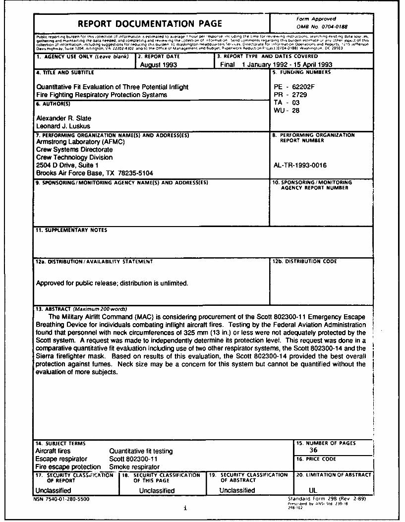
The Military Airlift Command (MAC) is considering procurement of the Scott 802300-11 Emergency EscapeBreathing Device for individuals combating inflight aircraft fires. Testing by the Federal Aviation Administrationfound that personnel with neck circumferences of 325 mm (13 in.) or less were not adequately protected by theScott system. A request was made to independently determine its protection level. This request was done in acomparative quantitative fit evaluation including use of two other respirator systems, the Scott 802300-14 and theSierra firefighter mask. Based on results of this evaluation, the Scott 802300-14 provided the best overallprotection against fumes. Neck size may be a concern for this system but cannot be quantified without theevaluation of more subjects.
14. SUBJECT TERMS 15. NUMBER OF PAGESAircraft fires Quantitative fit testing 36Escape respirator Scott 802300-11 16. PRICE CODEFire escape protection Smoke respirator17. SECURITY CLASSOICATION 18. SECURITY CLASSIFICATION 19. SECURITY CLASSIFICATION 20. LIMITATION OF ABSTRACT
OF REPORT OF THIS PAGE OF ABSTRACT
Unclassified Unclassified Unclassified ULNSN 7540-01-280-5500 Standard Form 298 (Rev 2-89)
QUANTITATIVE FIT EVALUATION OF THREEPOTENTIAL INFLIGHT FIRE FIGHTING
RESPIRATORY PROTECTION SYSTEMS
INTRODUCTION
Fires in the interior of Military Airlift Command (MAC) air-craft during flight are not common, but must be extinguished imme-diately if one should occur. The most common "injury" sufferedduring fires of any sort is smoke inhalation. Therefore, individ-uals who combat aircraft fires require respiratory protection fromthe smoke and toxic fumes of the fire. Personnel evacuating anaircraft during a fire may also require respiratory protection.
One mask system that MAC is considering buying to fulfillthis protection role is the Scott 802300-'l Emergency EscapeBreathing Device (11 EEBD) (Fig. 1). Federal .;;iation Administra-tion (FAA) personnel determined during 11 EEBD testing thatpersons with neck circumferences of 325 mm (13 in.) and less werenot adequately protected by the system. This discrepancy promptedMAC to request the Armstrong Laboratory (AL) to conductadditional, independent testing of the 11 EEBD to determinewhether there actually is a problem for persons with small necksand what levels of protection could be expected with the 11 EEBD.
The 11 EEBD was originally developed as a shipboard escapesystem for U.S. Navy use. This breathing device is a double hoodsystem that uses a neckdam. The 11 EEBD consists of Teflon Coated
Fiberglas Cloth underhood with a Kynol® fabric overhood and a neck-dam constructed of 0.075 mm (0.003 in.) polyurethane film (Fig.2). The system has a "neckpack" mounted in the back of the hoodthat contains a solid-state oxygen generator (good for 15 min ofoperation) and a carbon-dioxide (CO 2) scrubber (Fig. 3). Duringnormal operation the oxygen (02) generator supplies 5 1pm of 100%02 passing through a venturi nozzle. The acceleration in 02 flowrate is used to pull 55 1pm of air from the hood through the CO2scrubber to be returned to the hood free of CO2 so that it may safe-ly be reused. A complete flow schematic is provided in Figure 4.
Because of the limitations of quantitative fit testing, amask was needed to act as a basis of comparison. The Sierrafirefighter mask (Fig. 5) was chosen for this purpose. Thefirefighter mask is a full-face seal mask which is connected via aregulator to a compressed air tank. The mask comes in only onesize and relies upon an adjustable head harness and a constant airflow to maintain protection.
The test had two objectives: (1) to compare the 11 EEBD tothe Sierra firefighter mask (the 14 EEBD mask was added later) anddetermine relative protection capabilities, and (2) to determinewhether persons with necks smaller than 325 mm could safely usethe 11 EEBD.
1
Figure 1. Scott 802300-11 emergency escape breathingdevice (side view).
Figure 2. Scott 802300-11 neckdam.
2
Figure 3. N ec k p ack f r 0 a S 0~ 8C0230C-C BE -D (c 3v ~r eIIC, ()
PULL TO AC T. SOLID STATE.4C OXYGEN SUPPLYLI
HOOD 4 1 ~~GENEPATOR ý -~LL
A L V
/VENTURI NOZZLE
FILTER
VENT SCRUBBERVALVE
Figure 4. Scott EEBD Scuemat ic wihar: >.*pz
,:ilerra f'Lrefighter mask.
TEST PROCEDURES
a~> S s'a týýsed using th E- AL salt foguu:.Lt± ~- nT) sl -t~em. MAC provide-d the 11 EEBDs
Scmt aif~h~ aS s f or the testing. Additionally,.7 ~ rccac~o~cthat we test the improved version of the
E E.`Ký Emergency Escape Breathing Device (14* VA- r~z i-fference between the 11 EEBD and the 14Fl................~i of the 14 EEBD is constructed of 1.5625
:cj.iT s-Ystem u-ses a dr-y salt aerosol (0.28 ý.tm
-C- ' o a 20 mng in-: concentration). Samplingc - continuous 3.0 1pm sample from inside
0t-ested and the exposure booth. Salt-emin'ed using flame photometry. A
- v nof the salt fog system may be foundP% 3 'Sodium Chloride Respirator Fit Test
Sn e ts, including eight females, participated inthe eva '-brct had a beard, and four subjects woreglasses No- Lhr subj'ects who wore glasses did so whilewear-nq th f,, -- qte mask, but two did while wearing the EEBDs.
*Koiesar, Edward S., Jr., and Colette M. de la Barre. Sodiumchloride respirator quantitative fit test instrument. USAFSAM-TR-31-22, Nove~mb'er 1981.
4
Neck sizes ranged in circumference from 278 mm (11.2 in.) to 415mm (16.6 in.) . All eight female subjects had neck circumferencessmaller than 325 mm. A complete listing of subjects and theiranthropometric measurements may be found in Appendix A. A"pass/fail" fit factor of 10 was chosen arbitrarily, withoutobjection from MAC or Scott Aerospace.
Fit factor is a measure of mask protection. The fit factoris the dimensionless ratio of a contaminant outside the mask tothe amount of contaminant inside the mask. In laboratory testssuch as this, the contaminant is a simulant, in this case, sodiumchloride aerosol.
The EEBDs and the firefighter masks had to be modified toallow a sample probe to be placed inside the mask cavity. Sincethe presence of pure 02 causes a false low reading on the salt fogQnFT system, the EEBDs' 02 generators could not be used and theEEBDs were modified further to simulate the 02 generation.Additionally, since the 02 flaw also provides the motive force topull air from the hoods through the CO2 scrubbers, an alternativesolution to withdrawing air from the hoods was also necessary.
EEBD Modifications
To accomplish the EEBD modifications the two end caps on theneckpack were removed. Beneath these two caps are cavities (Figs.6 and 7). On one side (the inlet side) the 02 and air from thescrubber normally pass though the venturi nozzle and then enterthe hood. The end of the CO 2 scrubber was capped with a rubbergasket, and the end cap replaced with one that had been modifiedwith a bulkhead fitting. From here, a tee fitting led to twodifferent lines, one to the blower being used to pull air from thehood, and one leading to the mask testing panel.
Bottled compressed air was supplied to the EEBDs. Air to theEEBDs was controlled by a valve set so that the flow was aconstant 55 1pm.
The blower pulled 35 1pm from the EEBD hoods which wasexhausted into the exposure booth. In addition, sampling removed3 1pm, for a total of 38 1pm of air removed from the hoods.During normal operation here is a +5 1pm differential between theamount of air (02) added to the hood and the air removed from thehood. This excess air is exhausted through the neckdam seal.
In setting up the experimental conditions for thisevaluation, the primary concern was that no strains be imposed onthe system beyond those of normal use. This concern was moreimportant than duplicating the normal operating flows of the EEBDs(60 1pm inlet and 55 ipm scavenging) . In the test conditionsdescribed earlier there is a difference of 17 1pm between the 551pm inlet flow and 38 1pm outlet flow; 12 1pm greater than thenormal 5 1pm difference. The greater difference between inlet andoutlet was necessary because the 5 1pm flow of pure 02 from the
solid state generator had been replaced by normal air. Thedecrease in 02 content would result in increased subject
ventilation, placing a greater demand on the system. Theincreased difference between inlet and outlet flows compensatedfor this decreased 02 effect.
Firefighter Mask Modification
The firefighter mask was modified for the experiment by theinsertion of an AL developed probe between the air hose and themask. This probe allows a sample to be taken from the interior ofthe mask without destroying the mask. The probe design providesfor minimum interference with normal mask operation. Bottledcompressed air was supplied to the firefighter masks through afirefighter regulator (the flow was not measured).
Test Protocol
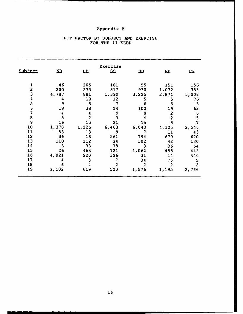
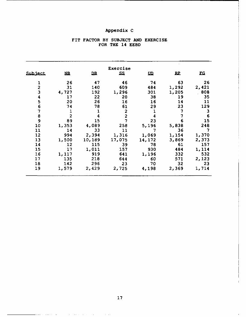
A six "%:-xercisell test protocol was used. The six exerciseswere (in the order performed) : (1) normal breathing, (2) deepbreathing, (3) moving the head from side-to-side, (4) moving thehead up-and-down, (5) reading a paragraph out loud, and (6) facialgrimacing. Each exercise was performed for 30 s. Fit factors foreach individual exercise are reported as well as an overall fitfactor. The overall fit factor is derived from the reciprocal ofthe arithmetic average for the six exercises. The equationdescribing the derivation (a harmonic mean) is:
The overall fit factors for the individual subjects are givenin Appendix A along with the neck circumference data. Fit factorsfor individual masks and individual exercises are given inAppendixes B through D.
To analyze the data statistically, a log base 10 transforma-tion is used. Nonparametric testing results show that the log-normal assumption is sufficiently close.
Ranking and Significance
Mean and median values for the overall fit factor are givenin Table 1. Both two-way analysis of variance (ANOVA) andDuncan's multiple range tests show the mask worn to be asignificant factor in three of the exercises, borderline for one,and significant for the overall fit factor. In all cases wherethere is significance, the 14 EEBD is better than the firefightermask. There is only one exercise where the 11 EEBD issignificantly better than the firefighter mask, and in no case are
7
the 11 EEBD and 14 EEBD significantly different. However, thereis a consistent ranking of mean and median values, with the 14EEBD getting the highest fit values, followed by the 11 EEBD, andthe firefighter mask getting the lowest values.
Table 1. Fit Factor Means and Medians of the Test System
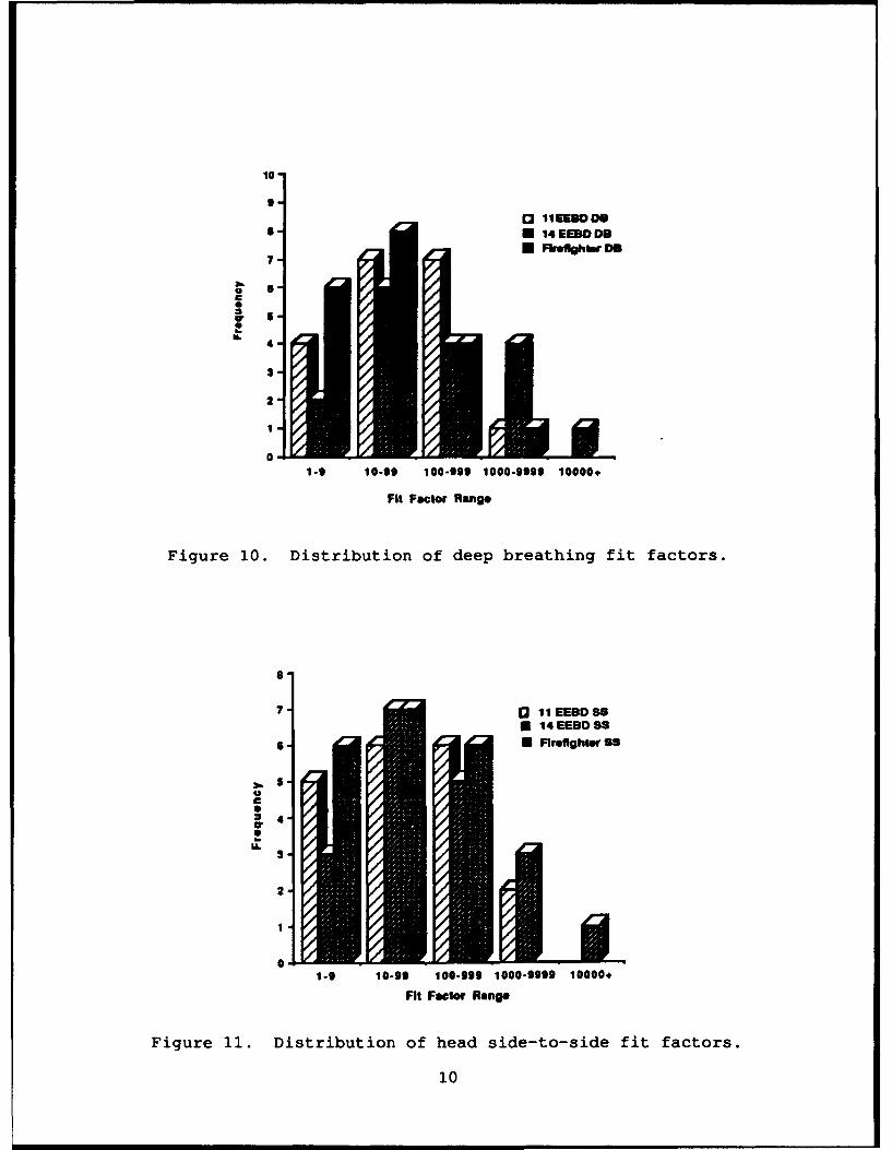
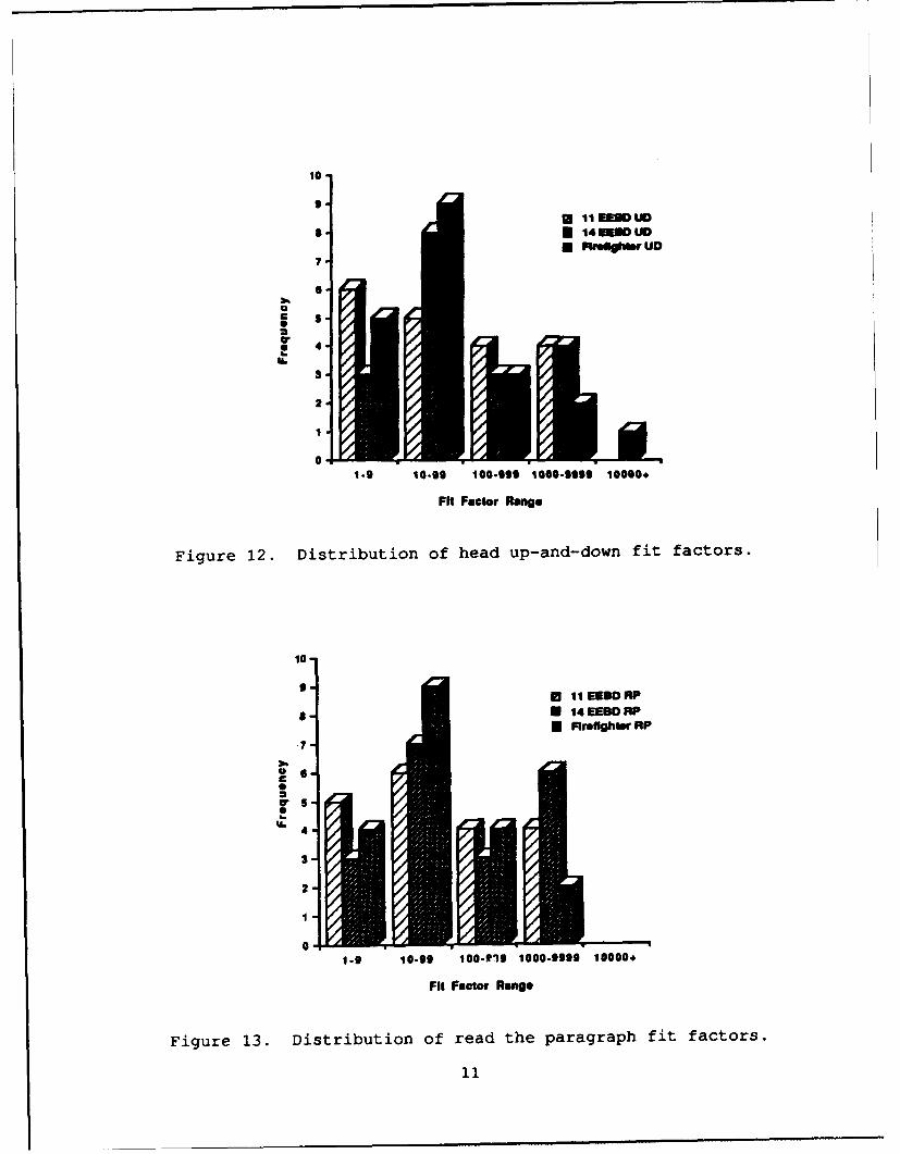
Examining the distribution of results by powers of ten (Table2 and the histograms in Figs. 8 through 14), the differencesbetween systems by fit factors are more apparent. The ranking ofthe three systems by fit factors is the 14 EEBD, the 11 EEBD, andfinally the firefighter mask.
Table 2. Distribution of Test Populationby Fit Factor Order of Magnitude
11 EEBD 14 EEBD Firefighter
100 6 2 6101 8 9 8102 3 5 5103 2 3 -
8
109-
* 0 11EEBDFFM 14 EEOD FF
7 M Firefighter FF
6C
a.
U. 4-
3-
2-
0-1-9 10-99 100-999 1000-9999 10000+
Fit Factor Range
Figure 8. Distribution of fit factors.
10
13 11 EEBD NO
8- 0 14 EEBD NO
0 F'ireflthter NO
6-0
C
wa.
. 4U.
2-
1-9 10-99 100-999 1000-9999 10000+
Fit Factor Rang.
Figure 9. Distribution of normal breathing fit factors.
9
10
o I1EEUDDB- 14 EEBD DMI
0 Frfghmr DS7-
o 6
I 6
w 52-
4
1-9 10-99 100-999 1000-9999 10000.
Fit Factor Range
Figure 10. Distribution of deep breathing fit factors.
7 ] 11 EEBDSS*14 EEBD 9S
*"U Flrefighter 98
0
S24
wiIL
2-
01-9 10-99 100-999 1000-9999 10000.
Fit Factor Rang*
Figure 11. Distribution of head side-to-side fit factors.
10
10
9* IEUDUD
I t 14 EE UODSFUelghblr Uo
7
.
0
Or4-3
* 4
21
0 11-9 10-9S 100-.99 1000-5995 10000*
Fit Factor Range
Figure 12. Distribution of head up-and-down fit factors.
10-
9-* 11EElD RP
. N 14 EEBD RP
7
2 S.U.5
I 4
S_
2
0
1-9 10-99 100-910 1000-9999 10000+
Fit Factor Range
Figure 13. Distribution of read the paragraph fit factors.
11
10
0S11 EEDlO FG
a U 14 EEBD FOM ftefightler FO
7
Cr
S 4.
3-
2
1
01-0 10-99 100-099 1000-9999 10000+
FFactor Range
Figure 14. Distribution of facial grimacing fit factors.
Order Effects
The test protocol called for varying the order in which themasks were worn during the test to not affect test results.Statistics were used to confirm this order. Three subject groupswore the masks in the following order: group one, 11 EEBD, 14EEBD, firefighter; group two, 14 EEBD, firefighter, 11 EEBD; andgroup three, firefighter, 11 EEBD, 14 EEBD. In no case were theresults from any particulai gcroup significantly different from anyother group's, and by mask and group a significant difference wasfound for only one exercise, head side-to-side. Since only onesignificant example of mask by group difference was found, weconcluded that the mask order did not affect the test.
Neck Size Effects
The effect of neck circumference on the test results for the11 and 14 EEBDs was also examined (NOTE: Neck circumference is nota factor for the firefighter mask.) since this was a concern basedupon the results of the early FAA test of the 11 EEBD. It isimportant to note that the factor affecting performance of theneck seal masks, are not clearly unaerstood and have never beenrigorously examined. (Similarly, few conclusions have been madeabout the performance of face seal masks with respect toanthropometrics and other factors.) Having worked with a varietyof neck seal masks, we suspect the following factors affect neckseal mask performance: neck circumference, the size and rigidityof the neck tendons, Adam's apple size and mobility, and the
12
amount of hair on the neck. Of these four factors, only the firstone, neck circumference, has been quantified at all.
Generally the shape of the curve comparing fit factor to neckcircumference for a neckdam sized for the 50th percentile memberof the population will be an inverted bathtub curve. Between acertain range of sizes the neckdam will perform relatively thesame, taking into account individual differences in head movementand breathing patterns. Below a certain neck size, the neckdamloses effectiveness, and there is a similar effect for very largenecks. This pattern is true for well fitting neckdams. The otherthree factors mentioned earlier have not been examined and are theresults of informal observations taken during fit tests of neckdam systems. All of these observations (neck circumference effectincluded) have been for negative pressure systems. Systems usingblown air with airflows greater than 3 cubic feet per minute inconjunction with neckdams have had consistently high levels ofprotection.
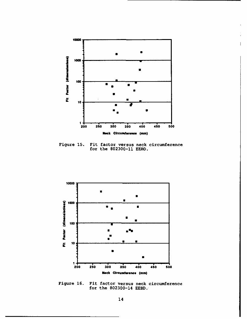
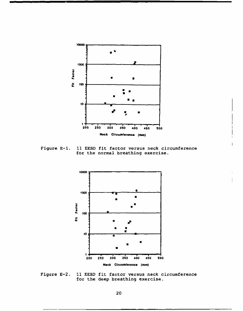
Figure 15 is the scatterplot of protection versus neckcircumference for the 11 EEBD and the overall fit factor; Figure16 illustrates the 14 EEBD. The plots for the individualexercises may be found in Appendixes E and F. These plots show noclear relationship between neck circumference and protection. Ofthe eight subjects with neck sizes smaller than 325 mm, three hadprotection levels less than 10 for the 11 EEBD where one was lessthan 10 for the 14 EEBD. There was one subject with a very largeneck (greater than 400 mm) who also scored consistently low withboth the 11 and 14 EEBDs. However, it is important to note thatof the number of protection failures (a fit factor less than 10),the percentage of subjects with neck circumferences less than 325mm or greater than 400 mm was always 66% or greater. Though thenumber of subjects for this experiment was not high enough toprove statistical significance, it appears that subjects withsmall necks run a greater risk of mask protection failures thansubjects with mid-range sized necks and that using the 14 EEBD canreduce this risk to a great extent.
CONCLUSION
Based on the results of this evaluation, it appears that noneof these masks will provide all personnel adequate protection incase of exposure to toxic fumes. In terms of fit factor, the bestof the systems tested is the 14 EEBD. Neck size appears to be ofsome concern for this system, but to determine the actualquantitative seriousness of this concern would need re-evaluationusing a panel with a greater number of subjects.
A need identified by this study is a standard for determina-tion of required protection levels. No standard was provided byMAC or Scott Aerospace for this test and the choice of a pass/failfit factor of 10 was arbitrary on the part of the investigators.It is recommended that more definitive sets of standards bedeveloped.
13
1.00- 1000
3 mm mm
L 10
200 250 3;0 350 400 450 Soo
Neck Circumlifenee (mm)
Figure 15. Fit factor versus neck circumferencefor the 802300-11 EEBD.