SERI/TP-252-3145 UC Category: 59a DE87012268 Adiabatic Air Dehumidification in Laminar Flow Desiccant Matrices Ahmad A. Pesaran July 1987 Prepared for the 1987 ASME Winter Annual Meeting Combined Heat and Mass Transfer in Porous Materials Session Boston, Massachusetts December 13-18, 1987 Prepared under Task No. 3071.210 FTP No. 1-721 Solar Energy Research Institute A Division of Midwest Research Institute 1617 Cole Boulevard Golden, Colorado 80401-3393 Prepared for the U.S. Department of Energy Contract No. DE-AC02-83CH10093
Transcript
SERI/TP-252-3145
UC Category: 59a DE87012268
Adiabatic Air Dehumidification in Laminar FlowDesiccant Matrices
Ahmad A. Pesaran
July 1987
Prepared for the
1987 ASME Winter Annual Meeting
Combined Heat and Mass Transfer in
Porous Materials Session
Boston, Massachusetts
December 13-18, 1987
Prepared under Task No. 3071.210
FTP No. 1-721
Solar Energy Research Institute A Division of Midwest Research Institute
1617 Cole Boulevard
Golden, Colorado 80401-3393
Prepared for the
U.S. Department of Energy Contract No. DE-AC02-83CH10093
NOTICE
This report was prepared as an account of work sponsored by the United States Government. Neither the United States nor the United States Department of Energy, nor any of their employees, nor any of their contractors, subcontractors, or their employees, makes any warranty, expressed or implied, or assumes any legal liability or responsibility for the accuracy, completeness or usefulness of any information, apparatus, product or process disclosed, or represents that its use would not infringe privately owned rights.
Printed in the United States of America Available from:
National Technical Information Service U.S. Department of Commerce
5285 Port Royal Road Springfield, VA 22161
Price: Microfiche A01 Printed Copy A02
Codes are used for pricing all publications. The code is determined by the number of pages in the publication. Information pertaining to the pricing codes can be found in the current issue of the following publications. which are generally available in most libraries: Energy Research Abstracts. (ERA); Government Reports Announcements and Index (GRA and I); Scientific and Technical Abstract Reports (STAR): and publication. NTIS-PR-360 available from NTIS at the above address.
ADIABATIC AIR DEHUKIDIFICATIOII Ill LAMIIIAR FLOW DESICCAHT MATRICES
A. A. Pesaran Solar Energy Research Institute
Golden, Colorado 80401
ABSTRACT
Adiabatic step transient heat- and mass-transfer and pressure drop experimental data were obtained for a dehumidifier test matrix that contained microbeadsilica-gel desiccant in a parallel-plate geometry. The data were analyzed and compared with the results of two other test dehumidifiers: a parallel-plate matrix using crushed ·silica gel, and a staggered, parallelstrip matrix using microbead silica gel. The analysis showed that the overall heat- and mass-transfer Nusselt numbers of the staggered, parallel-strip matrix were about 70% to 80% larger than those of the parallel-· plate matrices. It also showed that the solid-side resistance to moisture diffusion in the smaller microbead silica gel was about 45% less than that of crushed silica gel because the particle size was 60% smaller. The ratio of heat- or mass-transfer
·coefficient to pressure drop of the microbead-silicagel staggered, parallel-strip matrix was higher than the other two test dehumidifiers. Based on these findings, a dehumidifier using microbead silica-gel in a staggered, parallel-strip geometry can be made more compact than the other combinations.
a surface area per unit volume (1/m) A matrix wet surface area of coated tape (m2)
matrix minimum flow area (m2) heat or mass transfer hydraulic diameter (mm)
momentum hydraulic diameter (mm)
particle diameter (pm) mois.ture diffusivity in air (m2/s) moisture diffusivity in solid particles (m2/s) Fanning friction factor local Fanning friction factor for fully developed flow
1
f. 1 ith combined potential convective o gas-side mass transfer coef-2 ficient (kg/m s)
k thermal conductivity of moist air (W/m K) K pressure-drop coefficient 1 streamwise length of strips (pm) L axial length of the matrix (m) Le effective Lewis number
active mass of dry desiccant (kg) actual mass of dry desiccant (kg)
lila dry air mass flow rate (kg/s) Hu convective heat-transfer Husselt number Hu convective mass-transfer Nusselt number m ���0 overall mass-transfer Husselt number Hu0 overall heat-transfer Husseit number
number of heat-transfer units 11tu packing factor
'* Pf i& p pressure (Pa) .,,�
:r.��w. ..
Pr Prandtl number � ratio of effective mass to actual mass of dry desiccant (md/mdes)
Re Reynolds number s streamwise spacing between strips (pm)
gas-side mass-transfer resistance (sm2/kg)
overall .. ss transfer resistance (sm2/kg) solid-side mass transfer resistance (sm2/kg) temperature (K)
T' dimensionless temperature u air axial velocity in the channels (m/s) w humidity ratio (kg water/kg dry air)
w desiccant water content (kg water/kg dry desiccant)
air gap between sheets (�m)
total sheet thickness including the desiccant (�m)
Greek
a thermal diffusivity of air (m2/s)
-(aT/aw>F. 1
pressure drop (Pa)
solid-side geometry factor coefficient
dimensionless time
e time (s)
statistical mean, also viscosity (Ns/m2) 3p density (kg/m )
3density of particles (kg/m )
a standard deviation
solid-side geometry factor �c
Subscripts
1 related to first combined potential
2 related to second combined potential
i in
m mean value
0 out
s start
t total
T at constant temperature
fully developed value
HITRODUCTIOII
Solid desiccant cooling and dehumidification systems have received considerable attention in the past several years as alternatives or supplements to conventional vapor compression machines for air conditioning buildings and spaces that have high latent loads. A desi.:cant cooling involves passing humid (and warm) air through
sy$tem desiccant material for
drying and a cooler (evaporative or refrigerative) for cooling to provide conditioned air. The desiccant becomes saturated with water and needs to be regenerated with hot air provided by an energy source. For buildings, the energy source· can.
1gas, or off-peak electricity .* · be. the sun, natural
A desiccant cooling system generally consists of an adiabatic desiccant dehumidifier, a heater, a regenerative heat exchanger, and two evaporative coolers. Efficient and compact components having a low pressure drop should be used in desiccant systems so that they can compete with vapor compression systems on energy savings, size, and cost. The heart of any desiccant system is the desiccant dehumidifier. The performance of a dehumidifier depends on its geometry and the type of desiccant used. Silica gel, a porous
*The superscript numbers are reference nWilbers.
material, is usually recommended as the solid desiccant 1 for low-:temperature regeneration applications because
of its high moisture recycling capacity and other desirable properties. Laminar-flow channel geometries (e.g., parallel plate) have been recommended as those with high heat and mass transfer performances and low pressure drops2•
In a dehumidifier, heat and mass is transferred between air and the porous desiccant simultaneously� We must obtain the heat and mass transfer and pressure drop characteristics of a dehumidifier to evaluate its potential for use in desiccant cooling systems. � We have used adiabatic heat and mass transient e ts of gdehumidifiers to provide such characterizations ' •
This paper presents the results of experimental and theoretical efforts to investigate the simultaneous heat- and mass-transfer and pressure-drop characteristics of three laminar flow dehumidifier test matrices. These efforts also provided information as to which dehumidifier matrix performed more efficiently and would be sui table for desiccant cooling systems. This pa e is based on the results of two comprehensive � 6 reports ' • This work complements the previous· study
7of Maclaine-cross and Pesaran •
EXPERIMDITAL METHOD
Test Articles Initially we tested and analyzed two test articles
(a crushed-silica-gel parallel-plate matrix and a micro�e d-silica-gel staggered-parallel-strip ma,trix) ' • Because the material and geometry were changed simultaneously, some of the results were not conclusive. We then tested a microbead-silica-gel parall71-pgate matrix so we could make a· direct compar1son •
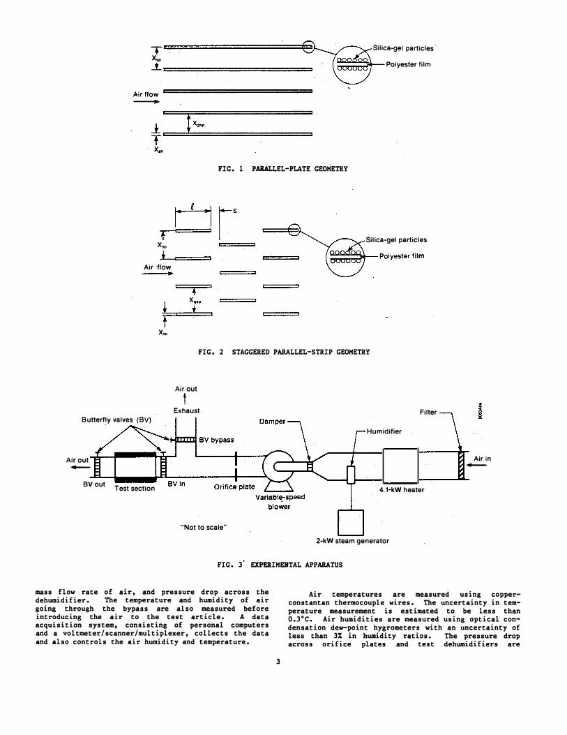
· All three test matrices were fabricated in the same manner. Both sides of a polyester tape were coated with fine particles of silica gel. The coated tape (or sheet) with spacers attached to both sides were stacked in a supporting metal frame and stretched from both ends to make uniform channels. This gave the channel walls a fine coating of desiccant particles. Fig. 1 shows the schematic of the parallel-plate geometry and Fig. 2 shows the schematic of the staggeredparallel-strip geometry.
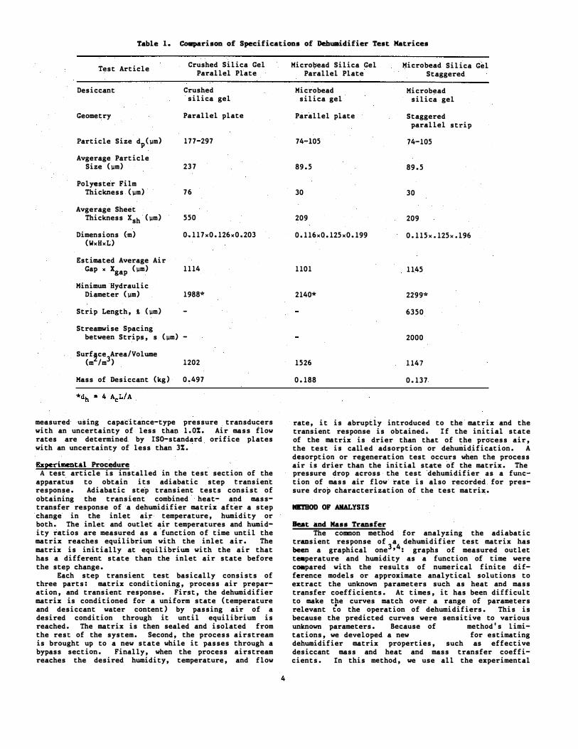
Crushed and microbead silica gels are both microporous and have practically the same thermophysical properties. The difference is that the ·crushed silica gel has larger particles (d = 177-297 �m) and i rregular shapes and the microbgad silica gel has smaller particles (d "' 74-105 J.JtD) with a more unHorm, .. spher-. p . . . . 1cal shape. Tab 1 e 1 compares t h e major spec1 f 1c.a.q,.o.ns of the three test dehumidifier matrices.
The Experi8ental Apparatus The experimental apparatus was fabricated to obtain
adiabatic step transient adsorption, desorption, and pressure drop data of a prototypical section Gf a desiccant dehumidifier. Fig. 3 shows a· schematic of the experimental apparatus. The apparatus consists of a duct heater, a humidifier, a variable speed blower, an orifice plate a test section' and instrumentation ' (hardware and software) for controlling and measuring temperatures, pressure drops, humidities, and airflow rates. The test section (which contains a test article, temperature sensors, air samplers for humidity measurement, and pressure taps) has a rectangular cross section of 0.161 m x 0.173 m and is 0.6 m long. The test section is insulated for adiabatic operation. Three butterfly valves are used to send air through the test section or through a bypass.
Important quantities to measure in these experiments are inlet and outlet temperatures and humidities,
2
· x i•• : t·
T � Silica-gel particles
. Polyester 1Im ========
Airflow-=================
-
FIG. 1 PARALLEL-PLATE GEOMETRY
+ x,. *
Air flow
x,.
Silica-gel particles
FIG. 2 STAGGERED PARALLEL-STRIP GEOMETRY
Air out
t Exhaust Filter
Butterfly valves (BV)
Air out -
BVout Test section
Humidifier
4.1-kW heater
"Not to scale"
2-kW steam generator
FIG. 3· EXPERIMENTAL APPARATUS
Air in -
mass flow rate of air, and pressure drop across the dehumidifier. The temperature and humidity of air going through the bypass are also measured before introducing the air to the test article. A data acquisition system, consisting of personal computers and a voltmeter/scanner/multiplexer, collects the data and also controls the air humidity and temperature.
Air temperatures are measured using copperconstantan thermocouple wires. The uncertainty in temperature measurement is estimated to be less than 0.3"C. Air humidities are measured using optical condensation dew-point hygrometers with an uncertainty of less than 3% in humidity ratios. The pressure drop across orifice plates and test dehumidifiers are
3
Table 1. Comparison of Specifications of Dehumidifier Test Matrices
Estimated Average Air Gap X x (pm) gap 1114 1101 1145
Minimum Hydraulic Diameter (pm) 1988* 2140* 2299*
Strip Length, t (pm) 6350
Streamwise Spacing between Strips, s (pm) - 2000
Surf�ce Area/Volume 3(m /m ) 1202 1526 1147
Mass of Desiccant (kg) 0.497 0.188 0.137
measured using capacitance-type pressure transducers with an uncertainty of less than 1.0%. Air mass flow rates are determined by !So-standard orifice plates with an uncertainty of less than 3%.
Ezperimental Procedure A test article is installed in the test section of the
apparatus to obtain its adiabatic step transient response. Adiabatic step transient tests consist of obtaining the transient combined heat- and masstransfer response of a dehumidifier matrix after a step change in the inlet air temperature, humidity or both. The inlet and outlet air temperatures and humidity ratios are measured as a function of time until the matrix reaches equilibrium with the inlet air. The matrix is initially at equilibrium with the air that has a different state than the inlet air state before the step change.
Each step transient test basically consists of three parts: matrix conditioning, process air preparation, and transient response. First, the dehumidifier matrix is conditioned for a uniform state (temperature and desiccant water content) by passing air of a desired condition through it until equilibrium is reached. The matrix is then sealed and isolated from the rest of the system. Second, the process airstream is brought up to a new state while it passes through a bypass section. Finally, when the process airstream reaches the desired humidity, temperature, and flow
4
rate, it is abruptly introduced to the matrix and the transient response is obtained. If the initial state of the ma�rix is drier than that of the process air,the test lS called adsorption or dehumidification. A d so ptio or regeneration test occurs when the process � : � a1r lS dr1er than the initial state of the matrix. The pressure drop across the test dehumidifier as a function of mass air flow rate is also recorded for pressure drop characterization of the test matrix.
MlrHOD OF ANALYSIS
Beat and Mass Transfer The common method for analyzing the adiabatic
transient response of a dehumidifier test matrix has been 3,4a graphical one : graphs of measured outlet teaperature and humidity as a function of time were co.pared with the results of numerical finite difference models or approximate analytical solutions to extract the unknown parameters such as heat and mass transfer coefficients. At times, it has been difficult to make the curves match over a range of parameters relevant to the operation of dehumidifiers. This is because the predicted curves were sensitive to various unknown parameters. Because of this method's 1 imi
5 7 tations, we developed a new technique • for estimating dehumidifier matrix properties, such as effective desiccant mass and heat and mass transfer coefficients. In this method, we use all the experimental
data points for extracting the unknowns rather than the judgmental curve-matching technique. This technique combines the moments method and heat and mass tran�fer analogy theory. A brief description of this method is given here.
In the heat and mass transfer analogy theory, the coupled heat and mass transport and conservation differential equations describing the behavior of a desiccant dehumidifier are transformed into sets of uncoupled differential equations describing t�e performance of two (F 1 and F 2) combined potentials • The combined potentials F1 and F2 (which are similar to enthalpy and moisture content) depend on temperature, humidity, and the properties of air/water-vapor/ desiccant. The combined potentials can then be treated like a heat-transfer-alone problem. The transient response (outlet temperature as a function of time) of a nondesiccant matrix (i.e., heat transfer alone) can be analyzed by the method of statistical moments9 to calculate the heat transfer coefficient. It can be shown using Laplace transforms (e.g., JeffersonlO) that the number of heat transfer units Nt for a constant specific heat system is related to �ormalized spread a!JJ by
(1)
where a/JJ is obtained from the moments method from
This moments method is iimilar to the "maximum slope" technique used by Locke to obtain heat transfer characteristics of several porous solids, which has been reported in Kays and London 1 s Compact Heat Exchangers. The Nusselt number may be calculated from the number of transfer units of flow, matrix dimensions, and fluid properties
N�""·;_ Re Pr Ntu Ac/ A • (3)
The advantage of this method is that all data points can be used. Electronic digital data loggers have a high reading rate.:',� and using all the data allows digitizing, which minimizes the random errors.
In the combined technique of statistical moments method and analogy theory, the experiment heat and mass transfer responses are first converted to the F1 and F2 responses; then they are treated as a heat-transferalone problem by the method of moments to obtain the number of transfer units for each potential [Eq. (1) and (2)] and then to calculate the Nusselt number of each combined potential Nu1 and Nu2 [from Eq. (3) ]. The heat and mass transfer analogy tneory is used once again to obtain the effective Lewis number Le (ratio of overall mass transfer resistance to overall heat transfer resistance) and overall heat transfer Nusselt number Nu0 from
1 - (a.·/a. 1 J · Le) i 1 ,2, j = 3-i • (4)
where
a.. 1 = -(aT/aW)F . i Then, the overall mass transfer Nu can be calculated mo from
(5)
5
The effective Lewis number is related through other properties of the matrix through the relation
a. . l;c Le=--+Nu0--, (6) w Tla
where the solid-f�de geometry factor coefficient 1; can c be obtained from
l;c = 6�pf (�) (P:Dw) (�=)T • (7)
The solid-side geometry factor n is a correction a factor to account for the desiccant particles that are not spherical and depends on the shape of the particles and how they cover the matrix geometrically. The factor, n ' can be estimated from Eq. a (4) and (6) if one knows the physical properties of air and the matrix and Nu1 and Nu2 from the analysis. The factor, n , should be a positive number and less than one. 'l{e overall mass-transfer resistance to moisture diffusion S0 is the sum of the gas-side resistance S g and the solid-side resistance ss; i.e.,
(8)
The gas-side resistance can be obtained from
(9)
where the gas-side mass-transfer coefficient hmg can be calculated from
(10)
Using the definition of the effective Lewis number, we can obtain
Ss = Sg(Le/(a/Dw) - 1) • (11)
Note that the effective Lewis number of 1 does not imply a zero solid-side diffusion resistance. When there is no solid-side resistance, the moisture diffusion in the solid is as fast as moisture diffusion in the air, and the effective Lewis number is a/D
The active mass of dry desiccant m•
d in tte matrix is estimated from the moisture transferred between the process air and the desiccant and the equilibrium isotherms of the desiccant:
B J e(W. 1 - W )m" dB 8 o a
s w e - w (12)
s
where (We - Ws) is the difterence between the moisture content of the matrix at the start and the end of the run.
0
Pressure Drop The measured pressure drop across a test matrix is
slightly different than the actual pressure drop because the measuring pressure taps are about 50 am upstream and downstream of the matrix. The actual, pressure drop across the matrix is
APactual = 4Pmeasured - APinlet - 4Poutlet • (13)
Inlet and outlet pressure drops were estimated using conservation of momentum and continuity. We can define the dimensionless 1 �ressure drop (according to Maclaine-cross and Ambrose ) by
'2 APactual d= h (fRe>actual (14) 2 lim Um L
where d� is the hydraulic diameter for momentum transfer ana can be different than the heat and mass transfer hydraulic diameter dh.
The Reynolds number in the parallel passages of the parallel-plate test matrices is between 100 to 500 and the flow is expected to be laminar. Assuming fully developed laminar flow and uniform parallel-plate passages and constant properties for the parallel-plate matrices, we can write
Re d' fRe = f .. Re m + K .. __!__h (15) 4L
where K.,. = 0.686 is the pressuri drop coefficient for entrance effect inside a passage 3 and f., is the local Fanning friction factor for fully developed flow. For a rectangular passage f., isl4
f = 24 1 (16) .. R e (1 + 2 Xgap/W) (1 - 0.6329249 Xgap I W) ,
where W is the width of the matrix.
The pressure loss across the staggered parallelstrip test matrix can be considered the summation of losses i� passages plus the downstream losses. It can be shown that
12 t.P dfRe h (17)
where
r' = K., + [K.. + 1 + Xgap ( )2 Xgap + Xsh
Xgap 2.4 ( ) X + X J X L/1
gap sh • (18)
The terms f.., and K., are the values for the parallelplate duct given before.
To estimate dehumidifier matrix characteristics from the step transient tests using the methods outlined in §his section, we developed a program called SINGLEBLOW in Pascal that runs on an IBM or a compatible personal computer. The specifications of the test matrix, such as dimensions and desiccant properties, are entered in the program; the program is run with the experimental data and Nu1 and Nu2, and otherpertinent values of the matrix are calculated.
RESULTS AID DISCUSSIOH
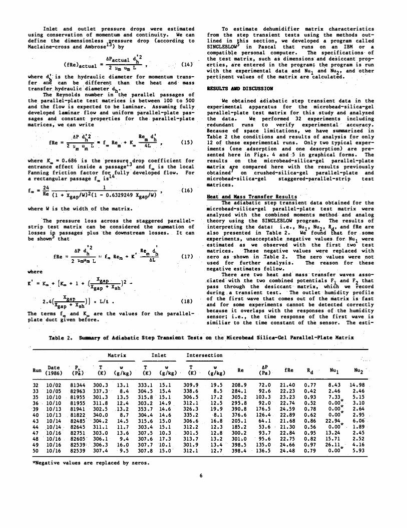
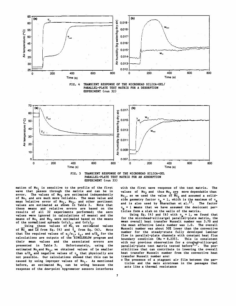
We obtained adiabatic step transient data in the experimental apparatus for the microbead-silica-gel parallel-plate test matrix for this study and analyzed the data. We performed 32 experiments including redundant runs to verify experimental accuracy. Because of space limitations, we have summarized in Table 2 the conditions and results of analysis for only 12 of these experimental runs. Only two typical experiments (one adsorption and one desorption) are presented here in Figs. 4 and 5 in graphical forms. The results on the microbead-silica-gel parallel-plate 111atrix '!{e compared here with the results previously obtained on crushed-silica-gel parallel-plate and microbead-silica-gel staggered-parallel-strip test ��&trices.
Heat and Mass Transfer Results The adiabatic step transient data obtained for the
microbead-silica-gel parallel-plate test matrix were analyzed with the combined moments method and analog theory using the SINGLEBLOW program. The results of interpreting the data: i.e., Nu , Nu , R , and fRe are 1 2 dalso .presented in Table 2. We found tllat for some experiments, unacceptable negative values for Nu1 were estimated as we observed with the first two test matrices. These negative values were replaced with zero as shown in Table 2. The zero values were not used for further analysis. The reason for these negative estimates follow.
There are two heat and mass transfer waves associated with the two combined potentials F1 and F2 that pass through the desiccant matrix, which we record during a transient test. The outlet humidity profile of the first wave that comes out of the matrix is fast and for some experiments cannot be detected correctly because it overlaps with the responses of the humidity sensor; i.e., the time response of the first wave is similiar to the time constant of the sensor. The esti-
Table 2. Summary of Adiabatic Step Transient Tests on the Microbead Silica-Gel Parallel-Plate Matrix
FIG. 5 TRANSIENT RESPONSE OF THE MICROBEAD SILICA-GEL PARALLEL-PLATE TEST MATRIX FOR AN ADSORPTION EXPERIMENT (run 33)
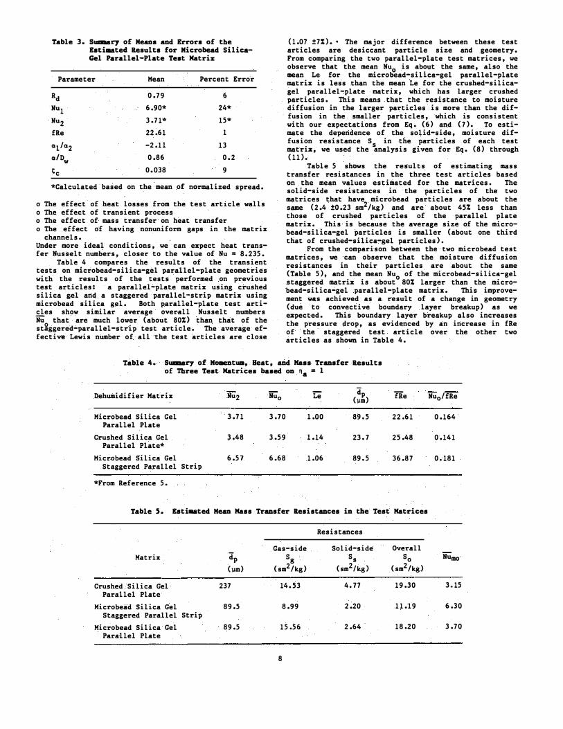
mation of Nu is sensitive to the profile of the first 1 wave that passes through the matrix and can be in error. The values of Nu are estimated independently 2 of Nu and are much more reliable. The mean value and 1 mean relative error of Nul' Nu , and other pertinent 2values are estimated as sliown 1n Table 3. Note that these means and relative errors are based on the results of all 32 experiments performed; the zero values were ignored in calculations of means; and the means of Nu and Nu were estimated based on the means 1 2 of the normalized spreads and
__ Using _!hese values Ca/11)
of Nu1'
we (a/)1)estimated
2• values i
of Nu and Le from Eq. (4) and n from Eq. (6). Note a that �he required values of a /a , � ' and i j c a/O for the w calculations are outputs of the SINGLEBLOW program and their mean values and the associated errors are presented in Table 3. Unfortunately, using the estimated Nu and Nu , we obtained values of Le smaller 1 �than a/D and negat1ve values of n that physically are w a not possible. Our calculations showed that this can be caused by using improper values of Nu1 • As mentioned before, an estimated Nu can be wrong because the 1 response of the de-point hygrometer sensors interferes
with the first wave response of the test matrix. The values of Nu and thus Nu more dependable than 2 2 Nu , so we used the value of
� Nu and assumed a solid1 2
side geometry factor n = 1, which is the maximum of na a 15and is also used by Bharathan et a1. • The factor n = 1 JDeans that we have assumed the desiccant partfcles form a slab on the walls of the matrix.
Using Eq. (4) and (6) with n = 1, we found that for the microbead-silica-gel paralfel-plate matrix, the mean overall heat transfer Nusselt number was 3.70 and ·the mean effective Lewis number was 1.0. The overall Husselt number was about 50% lower than the convective number for the steady-state fully developed laminar flow in parallel-plate channels with constant heat flux boundary condition (Nu = 8.235). This is consistent with our previous. observation for a crusf. d-silica-gel �parallel-plate test matrix tested before ' • The possibilities that can contribute to lowering the overall heat transfer Nusselt number from the convective heat transfer Nusselt number are: o The presence of a stagnant air film between the par
ticles and the main airstream in the passages that acts like a thermal resistance
7
Table 3. Suaaary of Means and Errors of the Estimated Results for Microbead SilicaGel Parallel-Plate Test Matriz
Parameter Mean Percent Error
Rd Nu1 Nu2 fRe
al/a2 a/Dw 1,;c
0.79
6.90*
3.71*
22.61
-2.11
0.86
0.038
6
24*
15*
1
13
0.2
9
*Calculated based on the mean of normalized spread.
o The effect of heat losses from the test article walls o The effect of transient process o The effect of mass transfer on heat transfer o The effect of having nonuniform gaps in the matrix
channels. Under more ideal conditions, we can expect heat transfer Nusselt numbers, closer to the value of Nu = 8.235.
Table 4 compares the results of the transient tests on microbead-silica-gel parallel-plate geometries with the results of the tests performed on previous test articles: a parallel-plate matrix using crushed silica gel and a staggered parallel-strip matrix using microbead silica gel. Both parallel-plate test articles show similar average overall Nusselt numbers iiU that are much lower (about 80%) than that of the stfective
gggered-parallel-strip test article. The average efLewis number of all the test articles are close
(1.07 ±7%). • The major difference between these test articles are desiccant particle size and geometry. From comparing the two parallel-plate test matrices, we observe that the mean Nu is about the same, also the mean Le for the micro�ead-silica-gel parallel-plate matrix is less .than the mean Le for the crushed-silicagel parallel-plate matrix, which has larger crushed particles. This means that the resistance to moisture diffusion in the larger particles is more than the diffusion in the smaller particles, which is consistent with our expectations from Eq. (6) and (7). To estimate the dependence of the solid-side, moisture diffusion resistance S in the particles of each test mat we used the �nalysis given for Eq. (8) through (11).
Table 5 shows the results of estimating mass transfer resistances in the three test articles based on the mean values estimated for the matrices. The solid-side resistances in the particles of the two matrices that have microbead particles are about the
2same (2.4 ±0.23 sm /kg) and are about 45% less than those of crushed particles of the parallel plate matrix. This is because the average size of the microbead-silica-gel particles is smaller (about one third that of crushed-silica-gel particles).
From the comparison between the two microbead test matrices, we can observe that the moisture diffusion resistances in their particles are about the same (Table 5), and the mean Nu 0 of the microbead-silica-gel staggered matrix is about 80% larger than the microbead-silica-gel parallel-plate matrix. This improvement was achieved as a result of a change in geometry (due to convective boundary layer breakup) as we ezpected. This boundary layer breakup also increases the pressure drop, as evidenced by an increase in fRe of the staggered test article over the other two articles as shown in Table 4.
.riz,
Table 4. Suaaary of MomentUIII, Heat, and Mass Transfer Results of Three Test Matrices based on na = 1
(a) (b) Enlarged view of lower lefthand corner of (a)
FIG. 6 COMPARISON OF EXPERIMENTAL AND PREDICTED DIMENSIONLESS PRESSURE DROP FOR THE THREE TEST MATRICES
,. r
The important parameters for comparing the three test articles are the ratio Hu /fRe and Le. The ratio Hu /fRe is a measure of rate o0 � heat transfer to pressure drop and is one measure of dehumidifier efficiency and size. The effective Lewis number is a measure of resistance to the moisture diffusion in the particles and decreases with particle size as can be seen from Table 4.
A dehumidifier performs better or can be more compa t with higher values of Hu /fRe and lower values of § pLe • Therefore, a dehumid1fier using the smaller microbead-silica-gel particles and staggered parallel strip geometry can perform more efficiently (or be more compact) compared with the other two dehumidifiers previously discussed. This could reduce the size and cost of desiccant cooling. systems. For further improvements in cost and performance, the focus should be on material choices and fabrication techniques.
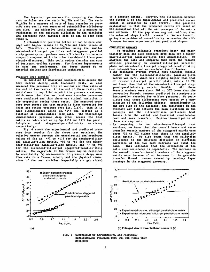
Pressure Drop Results In addition to measuring pressure drop across the
test matrix during each transient test, we also measured the pressure drop at various air flow rates at the end of two tests. At the end of these tests, the matrix was in equilibrium with the process airstream, which means that the heat and mass transfer processes were completed and thus there was minimal variation in air properties during these tests. The measured pressure drop across the test matrix is first corrected for inlet and outlet pressure drop [Eq. (13)]. Then it is made dimensionless using Eq. (14) and plotted as a function of dimensionless flow rate. The theoretical dimensionless pressure drop (fRe) across the test matrix is calculated using Eq. (15) and (17) for parallel-plate and staggered-parallel-strip matrices, respectively.
Fig. 6 shows the experimental and predicted pressure drop results for the three test matrices. The relative errors between the experimental and predicted values of fRe ar -7% to +17% for the crushed-silicagel parallel-pl!!-�1! matrix, -9% to +6% for the microbead-silica-gel •'\Sarallel-plate matrix, and -7 to +9% for the microb�ad-silica-gel staggered-parallel-strip matrix. T?e ma,�t tude of the errors may be explained 1by uncerta1nty �;n. measurements of pressure drop, mass 'flow rate to a lesser extent, and the physical dimensions of the test articles (especially air gap sizes)
.
to a greater extent. However, the difference between the slopes K of the experimental and predicted curves cannot be explained by such errors. One possible explanation is that the predicted curves are based on the assumption that all the air passages of the matrix are uniform. If the gap sizes ar not uniform, then1 � the value of slope K will increase • We are investigating the problem of nonuniformity to resolve the differences between experimental and predicted slopes.
COIICLUDIRC REMAilKS We obtained adiabatic transient heat- and mass
transfer data and also pressure drop data for a microbead-silica-gel parallel-plate test dehumidifier. We analyzed the data and compared them with the results obtained previously on crushed-silica-gel parallelplate and microbead-silica-gel staggered-parallel-strip test dehumidifiers and we concluded the following. o The estimated average overall heat transfer Husselt
number for the microbead-silica-gel parallel-plate matrix was 3.70, which was slightly higher than that of crushed-silica-gel parallel-plate. matrix (3.59) and lower than that of the microbead-silica-gel staggered-parallel-strip matrix (6 .68). All these Husselt numbers were about 40% to 55% lower than the convective Husselt numbers predicted by steady-state laminar-flow theories for uniform passages. We postulated that these differences were caused by a combination of the following effects: nonuniformity in the gap size of the passages; the resistance in the stagnant air film between the main airstream in the passages and the different-size particles; heat losses from the walls; and transient simultaneous heat and mass transfer. Further investigation of these are required.
o By comparing the two microbead-silica-gel test matrices, we found that the overall heat- and masstransfer Husselt numbers of the staggered matrix were about 70% to 80% higher than those in the parallelplate matrix. We also found that the solid-side
e resistance to the moisture diffusion in microbead particles of the two test matrices was about the same. This indicates that the . estimation of the solid-side resistance is dependable. The increase in the overall transfer Nusselt numbers of the staggered matrix were because of an increase in the gas-side transfer Husselt number caused by boundary layer breakups in the staggered geometry.
9
o By comparing the two parallel-plate test matrices, wefound that the overall heat-transfer Nusselt numbers of the two matrices were about the same, while theoverall mass transfer Nusselt number of the crushedsilica-gel matrix was 17% lower than the microbeadsilica-gel matrix. This was caused by a greater solid-side moisture diffusion resistance resulting from the larger crushed-silica-gel particles. The solid-side resistance in the smaller microbead silica gel (average particle size = 89.5 11m) was about 45% less than that in the larger crushed silica gel (average particle size = 237 11m).
o The mean overall mass-transfer Husselt number of thestaggered-strip matrix was 100% higher than the crushed-silica-gel parallel..,plate matrix because the 80% enhancement in gas-side transfer process and the20% enhancement in solid-side transfer process.
o Although the experimental pressure drops across the dehumidifiers were of the same magnitude as thetheory predictions, the slopes of the experimental curves were different than the slopes of the predicted curves. This difference could be explained if the test articles had nonuniform gap sizes. We are investigating the reason for the difference in trends of theoretical and experimental pressure drop curves.
0 The ratio of heat or mass transfer to pressure drop (Hu/fRe) of the microbead-silica-gel staggeredparallel-strip matrix was about 28% higher than that of the crushed-silica-gel parallel-plate matrix and 10% higher than that of the microbead-silica-gel parallel-plate matrix. Fabricating a dehumidifier with a staggered-parallel-strip geometry and microbead silica gel will result in a smaller and probably less expensive dehumidifier than one using crushed or microbead silica gel with a parallel-plate geometry.
This work was supported by the Solar Buildings Research and Development Program of the U.S. Department of Energy's Office of Solar Heat Technologies. I would like to thank J. Parsons for his contribution to the experimental part of this work.
REFEllEIICES
1. Jurinak, J. J., "Open Cycle Desiccant Cooling--Component Models and Systems Simulations," Ph.D. Dissertation, Madison, WI: University of Wisconsin, Solar Energy Laboratory, 1982.
2. Schlepp, D., and K. Schultz, "Analysis of Advanced Solar Hybrid Desiccant Cooling Systems for Buildings, 11 SERI/TR-252-2527, Golden, CO: Solar Energy Research Institute, 1984.
3. Kim, S., P. Biswas, and A. F. Mills, 11A Compact Low-Pressure Drop Desiccant Bed for Solar AirConditioning Application, 2: Bench Scale Tests, J. Solar Energy Eng., Vol. 107, 1985, pp. 120-127.
10
114. Bullock, c. E�.' and J. L. Threlkeld, D;humidi£-ication of Moist Air by Adiabatic Adsorption," Trans. Am. Soc. Heat Refris. Air-Condit. Ens., Vol. 72, 1966, PP• 301-313.
5. Pesaran, A. A., I. L. Maclaine-cross, and E. Van den Sulek, Measurements on Promising Dehumidifier Materials and Geometries, SERI/TR-252-2898, Golden, CO: Solar Energy Research Institute, forthcoming.
6. Pesaran, A. A., J. Parson, and K. Dukehart, Experiments on Desiccant Materials and Geometries for Desiccant Dehumidifiers; SERI/TR-252-3065 , Golden, CO: Solar Energy Research Institute, forthcoming.
7. Maclaine-cross, I. L., and A. A. Pesaran, "Heat and Mass Transfer Analysis of Dehumidifiers using Adiabatic Transient Tests," presented at the AIAA/ASME 4th Thermophysics and Heat Transfer Conference, June 1986, Boston, MA.
8. Banks, P. J., D. J. Close, and I. L. Maclainecross, "Coupled Heat and Mass Transfer in Fluid Flow through Porous Media--An Analogy with Heat Transfer," Proc. 4th Int. Heat Transfer Conf., Versailles, 1970.
9. Ruthven, D. M., Principles of Adsorption and Adsorption Processes, Hew York: John Wiley & Sons, Inc., 1984.
10. Jefferson, c. P., "Dynamic of Packed Beds with Intraphase Heat and Mass Transfer," Chemical Engineering Science, Vol. 23, 1968, pp. 509-523.
11. Locke, G. L., "Heat Transfer and Flow Friction Characteristics of Porous Solids," Technical Report No. 10, Department of Mechanical Engineering, Stanford University, Stanford, 1950.
12. Maclaine-cross, I. L., "A Theory of Combined Heat and Mass Transfer in Regenerators," Ph.D. Dissertation, Australia: Monash University, Department of Mechanical Engineering, 1974.
13. Maclaine-cross, I. L., and C. W. Ambrose, "Predicted and Measured Pressure Drop in Parallel-Plate Rotary Regenerators, 11 ASHE Journal of Fluids Engineering, Vol. 102, Mar. 1980, pp. 59-63.
14. Cornish, R. J., "Flow in a Pipe of Rectangular Cross-Section," Proceedings of the Royal Society, Sec. A, Vol. 120, 1928, pp. 691-700.
15. Bharathan, D., I. L. Maclaine-cross, and J. R. Parsons, Experimental Studies of Heat and Mass Exchange in Parallel-Passage Rotary Desiccant Dehumidifiers for Solar Cooling Applications, SERI/TR-252-2897, Golden, CO: Solar Energy Research Institute, forthcoming.