Federal Technology Alert A publication series designed to speed the adoption of energy- efficient and renewable technologies in the Federal sector Desiccant dehumidification technolo- gy provides a method of drying air before it enters a conditioned space. When combined with conventional cooling systems, desiccant dehumidifi- cation systems are a cost-effective means of supplying cool, dry, filtered air. These combined systems are called “hybrid” systems. This Federal Tech- nology Alert discusses how to evaluate the cost-effectiveness of hybrid two- wheel desiccant-based cooling systems, summarizes desiccant dehumidification process, reviews field applications, and examines energy savings and other benefits. Energy-Saving Mechanism Desiccant systems save energy by using low-grade thermal sources to remove moisture from the air and to eliminate the overcooling and reheat step necessary in certain conventional Two-Wheel Desiccant Dehumidification System Technology for Dehumidification and Improving Indoor Air Quality The U.S. Department of Energy requests that no alterations be made without permission in any reproduction of this document. vapor compression cooling systems. Desiccant systems often permit reduc- tions in the size of the conventional cooling system; this saves energy and decreases electrical demand. In some applications of hybrid desiccant-based systems, the vapor compression system can be replaced with less expensive direct or indirect evaporative cooling systems. Hybrid systems can provide year-round comfort. The direct or indirect heaters used for reactivation can supply comfort heating, and the heat wheel can be used to recover energy all year. Technology Selection The Federal Technology Alert series targets technologies that appear to have the greatest untapped federal-sector potential. Desiccant dehumidification technology is one of the many energy- saving technologies to emerge in the
Transcript
FederalTechnology
Alert
A publication seriesdesigned to speed the
adoption of energy-efficient and renewable
technologies in the Federal sector Desiccant dehumidification technolo-
gy provides a method of drying airbefore it enters a conditioned space.When combined with conventional cooling systems, desiccant dehumidifi-cation systems are a cost-effectivemeans of supplying cool, dry, filteredair. These combined systems are called“hybrid” systems. This Federal Tech-nology Alert discusses how to evaluatethe cost-effectiveness of hybrid two-wheel desiccant-based cooling systems,summarizes desiccant dehumidificationprocess, reviews field applications, andexamines energy savings and other benefits.
Energy-Saving MechanismDesiccant systems save energy
by using low-grade thermal sources to remove moisture from the air and toeliminate the overcooling and reheatstep necessary in certain conventional
Two-Wheel Desiccant Dehumidification System Technology for Dehumidification and Improving Indoor Air Quality
The U.S. Department of Energyrequests that no alterations bemade without permission in anyreproduction of this document.
vapor compression cooling systems.Desiccant systems often permit reduc-tions in the size of the conventionalcooling system; this saves energy anddecreases electrical demand. In someapplications of hybrid desiccant-basedsystems, the vapor compression systemcan be replaced with less expensivedirect or indirect evaporative coolingsystems. Hybrid systems can provideyear-round comfort. The direct or indirect heaters used for reactivation can supply comfort heating, and the heat wheel can be used to recover energy all year.
Technology SelectionThe Federal Technology Alert series
targets technologies that appear to havethe greatest untapped federal-sectorpotential. Desiccant dehumidificationtechnology is one of the many energy-saving technologies to emerge in the
last 20 years for commercial buildingsapplications. The hybrid two-wheel desiccant system has the potential for federal-sector energy savings and has demonstrated satisfactory field performance and reliability in specificapplications.
PotentialThe technology has been shown
to be technically valid and economicallyattractive in many applications. ThisTechnology Alert reports on the collec-tive experience of two-wheel desiccantsystem users and evaluators, and alsoprovides guidance to future applications.
ApplicationHybrid desiccant-based cooling
systems can be used in any buildingapplication. However, high initial coststypically limit the use of this technology.The systems are extremely effective, andtheir use is well established in condition-ing storage areas, ice arenas, hospitaloperating rooms, and supermarkets.
Site-specific conditions and differingapplication requirements must be understood before use of hybrid systemsin a building can be justified on eco-nomic grounds. A detailed analysis isgenerally required to evaluate the cost-effectiveness of a hybrid system with aconventional cooling system. Typically,hybrid systems should be considered ifthe following conditions are met:
• low indoor humidity (below 50°Fdew-point)
• high latent load fraction (greaterthan 25%)
• high fresh air intake (greater than 20%)
• high summer-time electric demandand energy costs, and low summer-time gas costs.
Field ExperienceDetailed performance evaluations
are still being conducted for two-wheeldesiccant system (TWDS) technologyinstalled in several Federal facilities.Several TWDS installations managed by U. S. Army Construction EngineeringResearch Laboratories (USACERL) atDefense Department sites are being evaluated; several other installations are in design stages. These systems usesteam from a gas-fired boiler for theirreactivation energy. In addition, theDesign and Construction Division ofDefense Commissary Agency (DCA) has installed over 70 desiccant-based systems in the past 10 years.
Six of the DCA units use heat recov-ery, and three have a TWDS design.Several facility managers for desiccantunits were contacted to ascertain systemperformance. Only one manager wasdissatisfied with the performance of theunit. This manager reported that thehumidity levels in the conditioned spacewere still high, and the sensible coolingwas inadequate. Both USACERL andDCA plan to install more desiccant systems in the future.
Case StudyInformation is available from the
Burger King demonstration site atAberdeen Proving Grounds, Maryland,where some of the critical variables weremonitored after the desiccant system wasinstalled. Fast food restaurants, largedining facilities, and other common areaspresent a unique situation, because of thehigh density of occupants. The effective-ness of the desiccant-based system at the Burger King site was evaluated as apossible solution for other such facilities.
This demonstration site is open 24-hours a day, seven days a week. The dining area initially had two packaged rooftop units (a 5-ton and a7.5-ton) supplying 700 cfm of ventila-tion out of a total supply flow rate of5,000 cfm. Although the peak designload matched the equipment nominalcapacity (12.5-ton) for the dining area,the components of the load (sensible andlatent) did not match the equipmentcapacities.
At the outset of the demonstration,the nominal-capacity of the two unitswas reduced from 12.5 tons to 10.5 tons,and the total latent capacity was lessthan the required design latent capacity.This shortage was exacerbated by off-design conditions, during which thelatent component of the total load did not drop off nearly as quickly as thesensible component. Because of theseproblems, the two packaged units wereunable to dehumidify and cool the airsimultaneously, resulting in frequent hotand/or humid conditions in the diningarea. As a remedy, a nominal 1,600 cfmTWDS manufactured by Engelhard/ICCwas installed. With this new system, theunit has operated reliably. An improve-ment in the space conditions was noticedby the restaurant employees and customers immediately.
Implementation BarriersA widespread use of the hybrid
desiccant cooling system is impeded by a lack of familiarity with the technology as well as a lack of knowledge about its performance and cost-effectiveness. Use of hybridsystems would be increased if therewere guidance and techniques for reducing the first cost of such systems,performance documentation and confirmation, design tools such as user-friendly computer programs,and utility incentives.
1
FederalTechnology
Alert
Two-Wheel Desiccant Dehumidification SystemTechnology for Dehumidification and Improving Indoor Air Quality
AbstractDesiccant dehumidification
technology provides a method of drying air before it enters a condi-tioned space. When combined withconventional vapor compression systems, desiccant dehumidificationsystems are a cost-effective means of supplying cool, dry, filtered air.
In the last decade, desiccant dehumidification technology hasemerged as an alternative or as a supplement to conventional vaporcompression systems for cooling andconditioning air in commercial andinstitutional buildings. A typicalhybrid system (shown above) com-bines a desiccant system with a conventional vapor compressioncooling system.
Desiccant-based systems are cost-effective because they use low-gradethermal sources to remove moisturefrom the air. In general, the benefitsof desiccant-based systems aregreater where the thermal energyrequired for regenerating the desic-cant is readily available, the electric-ity price is high, and the latent loadfraction is high (>25%). If there is nodifference in energy costs, the factorsthat influence the economy includeclimate conditions (humidities) and
high outdoor-air requirements. In other situations, the importantvariables that drive the economicsshould be carefully evaluated. Thereare, however, a few applicationswhere the technology’s benefits havebeen so extensively demonstrated that no detailed analysis is required:storage spaces, ice arenas, mostsupermarket applications, militarycommissaries, hospital operatingrooms, and as an add-on to existingair conditioning systems with inade-quate dehumidification capacity.
This Technology Alert providesinformation and procedures that aFederal energy manager needs inevaluating the cost-effectiveness of a desiccant system. The process ofdesiccant dehumidification and itsenergy savings and other benefits areexplained. Guidelines are providedfor appropriate application and installation. In addition to a method-ology of estimating energy savingspotential from desiccant systeminstallation, a case study is presentedto give the reader a sense of the actualcosts and energy savings. A listing of current manufacturers, technologyusers, and references for further reading is also included at the end of this report.
2
This page left blank intentionally
3
ContentsAbstract .................................................................................... 1About the Technology.............................................................. 5
Application DomainEnergy Savings MechanismOther BenefitsVariations in System Design and Operating ModesVariables Affecting PerformanceInstallation
Federal Sector Potential .......................................................... 10Application .............................................................................. 10
Application ScreeningWhere to Use Hybrid Desiccant Cooling SystemsWhat to AvoidDesign and Equipment IntegrationCostUtility Incentives and Support
Technology Performance ........................................................ 15Field PerformanceMaintenanceDesiccant LifeOther ImpactsHow to Estimate Energy Savings Potential
Case Study .............................................................................. 16Burger King RestaurantEvaluation of the Two-Wheel
Desiccant Demonstration SystemPreliminary Monitored Data from the
Commercial Desiccant SystemIndustrial and Military Desiccant System Manufacturers
Who is Using the Technology.................................................. 19For Further Reading ................................................................ 20
4
This page left blank intentionally
5
About the TechnologyAlthough there are a variety of
desiccant dehumidification technolo-gies, the primary focus of this Tech-nology Alert is the two-wheel desic-cant system (TWDS). Except whendescribing elements common to all desiccant-based systems, no other desiccant dehumidificationprocesses are discussed here.
Desiccant dehumidification technology has been used in militarystorage and many industrial applica-tions for more than 60 years (HarrimanIII 1990). Continuous desiccant dehumidification process can beachieved in a number of ways usingliquid spray-tower, solid packedtower, rotating horizontal bed, mul-tiple vertical bed, and rotating wheel.The TWDS falls into therotating wheel category.In such a TWDS, themoist air stream, whichhas a high vapor pres-sure, passes through arotating desiccant wheel. The desiccant,which has a low vaporpressure, adsorbs themoisture until the desiccant is saturated.Next, the saturated portion of the wheelrotates into a hot airstream, which is forcedthrough the wheel toremove the moisturefrom the desiccant. The dried desiccant isrotated back into the
moist air stream, and the processrepeats itself. After it has beenregenerated (dried), the desiccant iscooled to lower its vapor pressure.
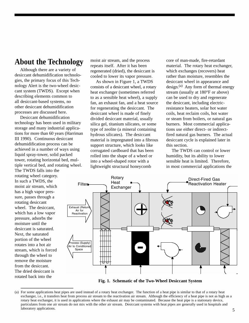
As shown in Figure 1, a TWDSconsists of a desiccant wheel, a rotaryheat exchanger (sometimes referredto as a sensible heat wheel), a supplyfan, an exhaust fan, and a heat sourcefor regenerating the desiccant. Thedesiccant wheel is made of finelydivided desiccant material, usuallysilica gel, titanium silicates, or sometype of zeolite (a mineral containinghydrous silicates). The desiccantmaterial is impregnated into a fibroussupport structure, which looks likecorrugated cardboard that has beenrolled into the shape of a wheel orinto a wheel-shaped rotor with alightweight structural honeycomb
core of man-made, fire-retardantmaterial. The rotary heat exchanger,which exchanges (recovers) heatrather than moisture, resembles thedesiccant wheel in appearance anddesign.(a) Any form of thermal energystream (usually at 180°F or above)can be used to dry and regenerate the desiccant, including electric-resistance heaters, solar hot watercoils, heat reclaim coils, hot water or steam from boilers, or natural gasburners. Most commercial applica-tions use either direct- or indirect-fired natural gas burners. The actualdesiccant cycle is explained later inthis section.
The TWDS can control or lowerhumidity, but its ability to lower sensible heat is limited. Therefore,in most commercial applications the
Fig. 1. Schematic of the Two-Wheel Desiccant System
(a) For some applications heat pipes are used instead of a rotary heat exchanger. The function of a heat pipe is similar to that of a rotary heatexchanger, i.e., it transfers heat from process air stream to the reactivation air stream. Although the efficiency of a heat pipe is not as high as arotary heat exchanger, it is used in applications where the exhaust air may be contaminated. Because the heat pipe is a stationary device,particulates from one air stream do not mix with the other air stream. Desiccant systems with heat pipes are generally used in hospitals and laboratory applications.
Exhaust (Return)Air for
Reactivation
RotaryHeatExchanger
FilterDirect-Fired GasReactivation Heater
+
- 100
100
Process (Supply)Air to Conditioned
Space
6
TWDS is supplemented with either avapor compression or an evaporativecooling system. These “hybrid”systems are described later in theTechnology Alert (henceforth, muchof the discussion in this TechnologyAlert will be focused on the hybridsystems).
Although the technology has beenproven in industrial environments,there is limited field test data to evaluate the long-term performanceof the TWDS in commercial buildingapplications. The first cost of thehybrid desiccant system is generallyhigher than that of conventional systems, but this is offset by loweroperating costs in certain applications(Manley et al. 1985; Burns et al.1985; Cohen and Slosberg 1988;Marciniak et al. 1991; Novosel 1996).The TWDS offers many other ben-efits in addition to operational cost-savings. These benefits will be highlighted later in the section.
Most commercial systems aredesigned to maximize the energy costsavings and minimize the initial cost.To optimize the benefits of hybridsystems, an understanding of theimpacts of the technology, the loadbeing served (latent versus sensible),and the climate in which it is operat-ing are all essential parameters.These topics are reviewed below.
Application DomainDesiccant systems have been
widely used in applications where theprime consideration is special systemrequirements rather than energy efficiency or competitive pricing(such as the military and industrialsectors). They have been successfulin these instances because there areno practical alternative processes thatare capable of providing low moisturelevels (less than 30°F dew-point), lowmicrobial growth, or improved indoorair quality. In the residential and thecommercial building sectors, desic-cant technology currently competeswith the well-established conven-tional vapor compression technology.Unfamiliarity with the technology,
and lack of assurance and educationabout the performance and cost-effectiveness of hybrid desiccantcooling systems, impede implemen-tation of such systems (Mei et al.1992).
Although no firm shipment numbers are available, the buildingsector has seen significant growth ininstallation of hybrid systems in thepast few years. This indicatesincreased awareness that hybrid desiccant systems can provide bothtemperature and humidity control andin some applications use less energythan conventional vapor compressionsystems. The applications where thebenefits have been extensivelydemonstrated include dry storagespaces, ice arenas, most supermarketapplications, military commissaries,hospital operating rooms, schools,fast-food restaurants, unheated warehouses, and as an add-on toexisting air conditioning systems withinadequate dehumidification capacity.
The following would encourageincreased use of hybrid systems:guidance and techniques for reducingthe first cost of hybrid desiccantcooling systems; performance docu-mentation and confirmation by anagency such as the Department ofEnergy (to encourage governmentfacilities’ managers and their archi-tects and engineers to objectivelyevaluate desiccant technology forlarge- and medium-sized buildingprojects); development of designtools (such as a user-friendly com-puter program) to enable designers to easily evaluate economic tradeoffsand design hybrid desiccant coolingsystems based on actual performancedata; and utility incentives (Mei 1992).
Energy Savings MechanismThe energy-saving mechanism of
a TWDS can best be understood bycomparing the dehumidification andcooling process of the conventionaland the desiccant-based systems.Both systems can be operated in various modes (recirculation, pure
ventilation, and mixed). Thesemodes will be discussed later in theTechnology Alert, but to illustrate theenergy savings feature, it is assumedthat both systems take in 100% outdoor air.
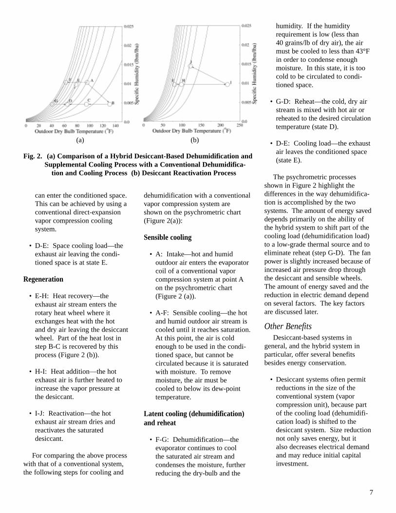
The following steps describe thepsychrometric process for a hybriddesiccant dehumidification and supplemental cooling system (the letters correspond to state points onthe psychrometric chart in Figure 2).
Dehumidification
• A: Intake—hot and humid outdoor air enters the desiccantwheel at point A on the psychrometric chart (Figure 2 (a)).
• A-B: Dehumidification—as themoisture from the outdoor air isremoved by sorption, the heatgenerated when the water issorbed (akin to condensation)remains in the air stream, increas-ing the air stream’s sensible load.There is a slight increase in theenthalpy (i.e., the energy contentof the air stream increases), whenlatent heat is being converted intosensible heat. At state B, the airis hot and dry and cannot bedirectly used to cool the condi-tioned area.
Cooling
• B-C: Heat loss or post-cooling—the dehumidified outdoor airenters the rotary heat wheel,where it exchanges heat with theexhaust (return) air stream fromthe conditioned space. In thisprocess, the hot and dry outdoorair cools down, and the coldexhaust air is pre-heated for reactivating the desiccant wheel.
• C-D: Supplemental cooling—theair leaving the rotary heat wheelis colder than the air leaving thedesiccant wheel, but further cooling is often required before it
7
can enter the conditioned space.This can be achieved by using aconventional direct-expansionvapor compression cooling system.
• D-E: Space cooling load—theexhaust air leaving the condi-tioned space is at state E.
Regeneration
• E-H: Heat recovery—the exhaust air stream enters therotary heat wheel where itexchanges heat with the hot and dry air leaving the desiccantwheel. Part of the heat lost instep B-C is recovered by thisprocess (Figure 2 (b)).
• H-I: Heat addition—the hotexhaust air is further heated toincrease the vapor pressure at the desiccant.
• I-J: Reactivation—the hotexhaust air stream dries and reactivates the saturated desiccant.
For comparing the above processwith that of a conventional system,the following steps for cooling and
dehumidification with a conventionalvapor compression system are shown on the psychrometric chart(Figure 2(a)):
Sensible cooling
• A: Intake—hot and humid outdoor air enters the evaporatorcoil of a conventional vapor compression system at point A on the psychrometric chart(Figure 2 (a)).
• A-F: Sensible cooling—the hotand humid outdoor air stream iscooled until it reaches saturation.At this point, the air is coldenough to be used in the condi-tioned space, but cannot be circulated because it is saturatedwith moisture. To remove moisture, the air must be cooled to below its dew-pointtemperature.
Latent cooling (dehumidification)and reheat
• F-G: Dehumidification—theevaporator continues to cool the saturated air stream and condenses the moisture, furtherreducing the dry-bulb and the
humidity. If the humidity requirement is low (less than 40 grains/lb of dry air), the airmust be cooled to less than 43°Fin order to condense enoughmoisture. In this state, it is toocold to be circulated to condi-tioned space.
• G-D: Reheat—the cold, dry airstream is mixed with hot air orreheated to the desired circulationtemperature (state D).
• D-E: Cooling load—the exhaustair leaves the conditioned space(state E).
The psychrometric processesshown in Figure 2 highlight the differences in the way dehumidifica-tion is accomplished by the two systems. The amount of energy saveddepends primarily on the ability ofthe hybrid system to shift part of thecooling load (dehumidification load)to a low-grade thermal source and toeliminate reheat (step G-D). The fanpower is slightly increased because ofincreased air pressure drop throughthe desiccant and sensible wheels.The amount of energy saved and thereduction in electric demand dependon several factors. The key factorsare discussed later.
Other BenefitsDesiccant-based systems in
general, and the hybrid system inparticular, offer several benefitsbesides energy conservation.
• Desiccant systems often permitreductions in the size of the conventional system (vapor compression unit), because partof the cooling load (dehumidifi-cation load) is shifted to the desiccant system. Size reductionnot only saves energy, but it also decreases electrical demandand may reduce initial capital investment.
Fig. 2. (a) Comparison of a Hybrid Desiccant-Based Dehumidification and Supplemental Cooling Process with a Conventional Dehumidifica-
tion and Cooling Process (b) Desiccant Reactivation Process
(a) (b)
8
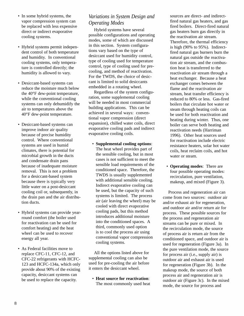
• In some hybrid systems, thevapor compression system can be replaced with less expensivedirect or indirect evaporativecooling systems.
• Hybrid systems permit indepen-dent control of both temperatureand humidity. In conventionalcooling systems, only tempera-ture is controlled directly; thehumidity is allowed to vary.
• Desiccant-based systems canreduce the moisture much belowthe 40°F dew-point temperature,while the conventional coolingsystems can only dehumidify theair to temperatures above the40°F dew-point temperature.
• Desiccant-based systems canimprove indoor air qualitybecause of precise humidity control. Where conventional systems are used in humid climates, there is potential formicrobial growth in the ducts and condensate drain pansbecause of inadequate moistureremoval. This is not a problemfor a desiccant-based systembecause there is typically very little water on a post-desiccantcooling coil or, subsequently, inthe drain pan and the air distribu-tion ducts.
• Hybrid systems can provide year-round comfort (the boiler used for reactivation can be used forcomfort heating) and the heatwheel can be used to recoverenergy all year.
• As Federal facilities move toreplace CFC-11, CFC-12, andCFC-22 refrigerants with HCFC-123 and HCFC-134a, which onlyprovide about 90% of the existingcapacity, desiccant systems canbe used to replace the capacity.
Variations in System Design andOperating Modes
Hybrid systems have several possible configurations and operatingmodes, some of which are discussedin this section. System configura-tions vary based on the type of desiccant used for humidity control,type of cooling used for temperaturecontrol, type of cooling used for pre-cooling, and method of reactivation.For the TWDS, the choice of desic-cant is limited to solid desiccantsembedded in a rotating wheel.
Regardless of the system configu-ration, some supplemental coolingwill be needed in most commercialbuilding applications. This can beachieved in several ways: conven-tional vapor compression (directexpansion), chilled water coils, directevaporative cooling pads and indirectevaporative cooling coils.
• Supplemental cooling options:The heat wheel provides part ofthe sensible cooling, but in mostcases is not sufficient to meet thesensible load requirements of theconditioned space. Therefore, theTWDS is usually supplementedwith additional sensible cooling.Indirect evaporative cooling canbe used, but the capacity of suchsystems is limited. The processair (air leaving the wheel) may becooled with direct evaporativecooling pads, but this methodintroduces additional moistureinto the conditioned spaces. Athird, commonly used option is to cool the process air usingconventional vapor compressioncooling systems.
All the options listed above forsupplemental cooling can also beused for pre-cooling the air before it enters the desiccant wheel.
• Heat source for reactivation:The most commonly used heat
sources are direct- and indirect-fired natural gas heaters, and gasfired boilers. Direct-fired naturalgas heaters burn gas directly inthe reactivation air stream.Therefore, the thermal efficiencyis high (90% to 95%). Indirect-fired natural gas burners burn thenatural gas outside the reactiva-tion air stream, and the combus-tion heat is transferred to thereactivation air stream through aheat exchanger. Because a heatexchanger comes between theflame and the reactivation airstream, heat transfer efficiency isreduced to 80% or less. Gas-firedboilers that circulate hot water orsteam through heating coils canbe used for both reactivation andheating during winter. Thus, oneboiler can serve both heating andreactivation needs (Harriman1996). Other heat sources usedfor reactivation include electricresistance heaters, solar hot watercoils, heat reclaim coils, and hotwater or steam.
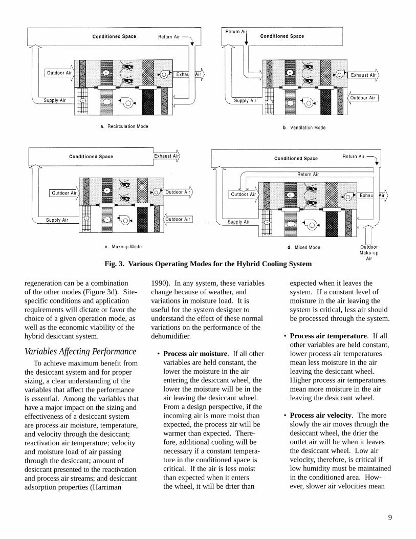
• Operating modes: There arefour possible operating modes:recirculation, pure ventilation,makeup, and mixed (Figure 3).
Process and regeneration air cancome from two sources: outdoor airand/or exhaust air for regeneration,and outdoor air and/or return air forprocess. These possible sources forthe process and regeneration airstreams can be pure or mixed. In the recirculation mode, the source of process air is return air from theconditioned space, and outdoor air isused for regeneration (Figure 3a). Inthe pure ventilation mode, the sourcefor process air (i.e., supply air) isoutdoor air and exhaust air is used for regeneration (Figure 3b). In themakeup mode, the source of bothprocess air and regeneration air isoutdoor air (Figure 3c). In the mixedmode, the source for process and
9
regeneration can be a combination of the other modes (Figure 3d). Site-specific conditions and applicationrequirements will dictate or favor thechoice of a given operation mode, aswell as the economic viability of thehybrid desiccant system.
Variables Affecting PerformanceTo achieve maximum benefit from
the desiccant system and for propersizing, a clear understanding of thevariables that affect the performanceis essential. Among the variables thathave a major impact on the sizing andeffectiveness of a desiccant systemare process air moisture, temperature,and velocity through the desiccant;reactivation air temperature; velocityand moisture load of air passingthrough the desiccant; amount of desiccant presented to the reactivationand process air streams; and desiccantadsorption properties (Harriman
expected when it leaves the system. If a constant level ofmoisture in the air leaving thesystem is critical, less air shouldbe processed through the system.
• Process air temperature. If allother variables are held constant,lower process air temperaturesmean less moisture in the airleaving the desiccant wheel.Higher process air temperaturesmean more moisture in the airleaving the desiccant wheel.
• Process air velocity. The moreslowly the air moves through thedesiccant wheel, the drier theoutlet air will be when it leavesthe desiccant wheel. Low airvelocity, therefore, is critical iflow humidity must be maintainedin the conditioned area. How-ever, slower air velocities mean
1990). In any system, these variableschange because of weather, and variations in moisture load. It is useful for the system designer tounderstand the effect of these normalvariations on the performance of thedehumidifier.
• Process air moisture. If all othervariables are held constant, thelower the moisture in the air entering the desiccant wheel, thelower the moisture will be in theair leaving the desiccant wheel.From a design perspective, if theincoming air is more moist thanexpected, the process air will bewarmer than expected. There-fore, additional cooling will benecessary if a constant tempera-ture in the conditioned space iscritical. If the air is less moistthan expected when it enters the wheel, it will be drier than
Fig. 3. Various Operating Modes for the Hybrid Cooling System
10
bigger and more costly desiccantwheels. The designer must installan airflow-monitoring device and control the system to avoidunplanned changes in velocity. If the moisture removal rate (pounds of moisture removed per hour) is more important than low humidity in the conditionedspace, then the air can passthrough the system at highervelocities, and smaller, less costly equipment can be used.
• Reactivation air temperature.The desiccant is dried and reactivated by a hot air stream.The hotter the reactivation air, themore easily the desiccant givesup moisture. If dry air is requiredin the conditioned space, highreactivation air temperatures(250°F) are generally the mosteconomical choice. If lowhumidity is not a requirement,inexpensive, low-grade heatsources, such as waste heat,cogeneration heat, or heat re-jected from refrigeration con-densers, can be used to reactivatethe desiccant at a low cost. Inthis case, the desiccant wheel willneed to be larger than the one ina high-temperature reactivationsystem in order to produce thesame outlet condition in theprocess air.
• Reactivation air moisture. Ingeneral, the moisture level of reactivation air does not affectsolid-desiccant wheel perfor-mance. However, leakage fromthe reactivation air stream to the process air stream will addmoisture to the process airstream. The units are designed to minimize leakage by keeping a positive pressure differentialbetween the process and regen-eration air streams and by placingseals around the rotor assembly.
• Reactivation air velocity. Theamount of moisture removedfrom the desiccant wheel is afunction of the reactivation airflow and the temperature difference between the reactiva-tion air and the desiccant wheel.The faster the reactivation airflows, the greater the moistureremoval from the desiccant. Ifthe temperature of the reactiva-tion air remains constant, it is awaste of energy to increase theairflow beyond the minimumvalue necessary to remove themoisture from the desiccantwheel.
• Amount of desiccant presentedto the air stream. Increasing the amount of desiccant that isavailable to dry the air in a fixedperiod of time increases themoisture removal capacity of thewheel and the amount of energyused in reactivation. The in-crease can be accomplished byincreasing the wheel depth orwheel rotation speed. Increasingthe wheel depth increases themass of the desiccant. This causes an increase in airflowpressure and increases the temperature of the air leaving the wheel. More energy mustthen be expended to cool this airbefore it enters the conditionedspace. Increasing the wheel rotation speed increases theamount of moisture removalbecause the desiccant wheelmoves faster between process andreactivation air streams. Again,more energy must be expendedfor both cooling and reactivation.In general, manufacturers designthe units to optimize the relation-ship between energy expenditureand moisture removal capacity.Therefore, the manufacturer usually establishes the rotationalspeeds and wheel depth(Harriman 1990).
• Desiccant adsorption character-istics. At constant temperature,each desiccant has a fixed capacity to sorb moisture. Ingeneral, manufacturers designunits to optimize the moistureremoval capacity for specifiedvalues of other variables such asair flow rates and wheel speed.
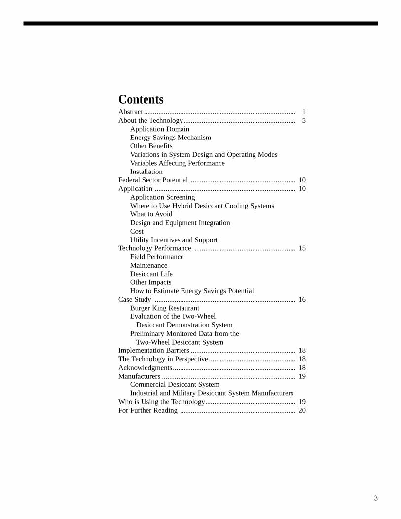
InstallationThe desiccant systems are gener-
ally designed for outdoor installation.Most commercial desiccant systemsare mounted on rooftops. The unitsare installed on concrete pads locatedas close as possible to the gas andelectrical interfaces. If the desiccantunit is equipped with an evaporativecooler, it will need water supply. In some large systems, a telephonehookup may be needed to remotelymonitor the unit’s operation. Clear-ance may not be an issue for rooftop-mounted units; units installed inenclosed spaces must have sufficientside access clearance for mainte-nance.
Federal SectorPotential
Although the desiccant technologyhas been employed for severaldecades, its use was limited to industrial and military sectors. Themarket potential in those sectors wasestimated to be between $50 millionand $60 million in the early 1990s(Mei et al. 1992). No concrete estimates are available either for the commercial buildings sector or for the Federal sector becausewider applications of the technologyare only now being investigated.
ApplicationThis section addresses technical
aspects of the hybrid desiccant cooling technology. The range ofapplications and climates in whichthe technology can best be applied is
11
discussed. The advantages and limitations are enumerated. Designand integration considerations of thetechnology are discussed, includingcosts, options, and installation details.Utility incentives are also presented.
Application ScreeningHybrid desiccant cooling systems
can be used in any building applica-tion because they provide precisetemperature and humidity control.However, high initial costs ($5/cfm to $8/cfm) typically limit the use ofdesiccant technology.
Several techniques can be used toestimate the annual energy consump-tion of hybrid desiccant cooling systems. The most accurate are thosethat use computer simulations.Although they produce more reliableresults than hand-calculation tech-niques, computer simulations are difficult and expensive to employroutinely as initial screening tools,and are therefore appropriate onlywhen additional details are required.
The bin method is another analyti-cal tool for screening technologyapplications. In general, a binmethod is a simple calculation procedure that is readily adaptable to a spreadsheet-type analysis and can be used to reasonably estimatethe energy consumption of a givenapplication in a specific location(ASHRAE 1993, Chapter 28).However, the bin method underesti-mates the latent load by about 30%,because the methodology relies onusing dry-bulb temperature bins withaverage coincident wet-bulb tempera-tures. An alternate approach is to usejoint frequency tables of dry-bulbtemperatures and humidity ratio. Thedifficulty with this approach is thathourly humidity ratios are not readilyavailable.
Where to Use Hybrid DesiccantCooling Systems
Site-specific conditions and differing application requirements
must be understood before use ofdesiccant-based hybrid systems in abuilding can be justified on economicgrounds. A detailed analysis is generally required to compare thecost-effectiveness of a hybrid systemwith a conventional cooling system.While it is difficult to generalize thecost-effectiveness of the hybrid systems, there are a few applicationswhere cost-effectiveness is so wellestablished that detailed analysis isnot necessary. These include storagespaces (where the space is dehumidi-fied in summer and heated in winter),ice arenas that operate in summer,hospital operating rooms (wherehumidity control and indoor air quality are critical), and most super-markets. In a situation where theexisting conventional system isunable to provide sufficient latentcapacity, a TWDS can be integratedwith the existing system to providethe necessary latent capacity. In sucha situation, the first cost usuallyfavors a TWDS over a conventionalsystem.
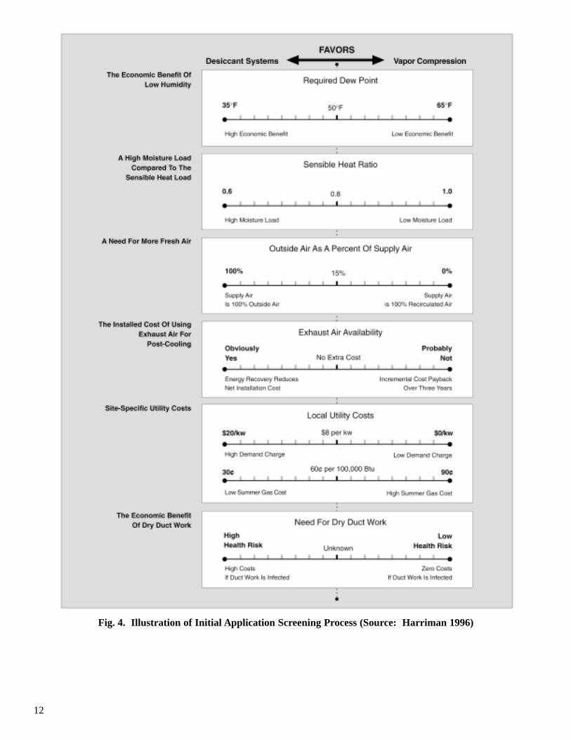
For other situations the key variables that drive costs should becarefully evaluated. These includemaximum allowable moisture level in the conditioned space, ratio of thelatent cooling load to the sensiblecooling load, amount of fresh airrequired, design outdoor dew-pointtemperature, availability of exhaust(return) air for post-cooling, localelectric demand and energy costs,local gas cost, availability of cheapregeneration heat, and the benefits of improved indoor air quality. Thefollowing application criteria can be used (Figure 4):
• Level of Indoor Humidity:Desiccant-based systems are themost economical choice to dehumidify air below 40°F dew-point, because condensate oftenfreezes on the coils of conven-tional cooling systems at tem-peratures below 40°F, therebyreducing the coil moisture
removal capability. If the dew-point requirement is between40°F and 50°F, the cost-effective-ness of desiccant-based systemsdepends on the other site-specificconditions and requirements. Ifthe dew-point requirement isgreater than 50°F, a conventionalsystem is generally favored. Inmost commercial building applications, deep drying (dew-point <40°F) is rare. The recom-mended level of indoor dew-pointfor a typical office building isbetween 51°F and 57°F, while thelevel for libraries and museums isbetween 46°F and 54°F.
• High Latent Load Fraction(>25%): Desiccant-based systems are more cost-effectivein reducing latent loads than areconventional systems; therefore,they are more attractive when thelatent loads as a fraction of thetotal loads are high. In mostoffice buildings, the latent loadsare a small fraction of the totalload (less than 25%). However,supermarkets, movie theaters,schools, auditoriums and outside-air ventilation systems have amuch higher fraction of latentloads.
• Fresh Air Intake: Some com-mercial buildings (schools,hospitals, restaurants, and retailestablishments) require signifi-cant fresh air intake (greater than20%) (ASHRAE Standard 62). Ifthe design dew-point temperatureand the frequency of high outdoordew-point temperatures are high,desiccant-based systems may becost-effective. ASHRAE haspublished 1%, 2%, and 5% occurrences of extreme dew-pointtemperatures and mean coinci-dent dry-bulb temperatures(Colliver et al. 1995). It is difficult to get the actual fre-quency of occurrences of dew-point temperatures for various
12
Fig. 4. Illustration of Initial Application Screening Process (Source: Harriman 1996)
13
climate regions, but frequency of mean coincident wet-bulb(MCWB) temperatures are readily available to most Federalenergy managers (TM 5-785,1978). However, calculationsusing MCWB temperatures maylead to underestimates of thelatent ventilation load.
• Availability of Exhaust (Return) Air for Post-Cooling:If exhaust (return) air is availablefor post-cooling (as shown inFigure 3b), the sensible coolingrequirements are reduced. If thefresh air requirements are high(greater than 20%), desiccant-based systems that use a combi-nation of fresh and exhaust aircan be more cost-effective thanconventional cooling systems.
• Demand and Energy Costs:High summer-time electricdemand and electricity cost,coupled with a low summer gascost, can favor desiccant systems.Low gas costs alone may notmake the desiccant-based systemscost-effective, and other criteriashould be carefully evaluated.
• Availability of Cheap/FreeReactivation Energy Source:Availability of free or cheap reactivation heat will make desiccant-based systems moreattractive. In general, 180°F to220°F temperatures are requiredfor regeneration. Some possiblesources of “waste” heat are condensers, engines, and gas turbine exhaust.
• Indoor Air Quality: Indoor airquality is difficult to quantify in terms of economic benefit,but is essential for many build-ings (e.g., hospitals and nursinghomes). Desiccant-based sys-tems improve indoor air qualitybecause they precisely controlmoisture levels. Where conven-tional systems are used in humid
climates, there is potential formicrobial growth in the ducts andcondensate drain pans because of inadequate moisture removal.This is not a problem for a desiccant-based system becausethere is typically very little wateron a post-desiccant cooling coilor, subsequently, in the drain panand the air distribution ducts.
When two or more of the key variables favor a hybrid system over a conventional system, the buildingmanager should request a detailedanalysis of the benefits of a hybriddesiccant system.
What to AvoidThe hybrid desiccant cooling
system may be less attractive
• if the conditioned space dew-point requirement is higher than 50°F
• if the latent fraction of the totalcooling load is less than 25%
• if the designers and installers are inexperienced. As with any heating or air-conditioningsystem, approved calculation procedures should be used for sizing.
Design and EquipmentIntegration
The purpose of this TechnologyAlert is to familiarize the Federalenergy managers and Federal facilityengineers with the benefits and liabilities of using desiccant coolingsystems and their application to commercial facilities. Because anydesiccant-based system needs to beoptimized to a specific site condition,it is beyond the scope of this Technol-ogy Alert to fully explain the designrequirements of a particular desiccantcooling system. In general, the system should be designed by anexperienced designer and installer ofthese systems. It is, however, impor-tant that the reader know the basic
steps in the design process, which are listed below:
• Determine local climatic designconditions, e.g., design dry-bulband dew-point temperatures.
• Establish the control levels (temperature and humidity).
• Determine building heating andcooling loads (both latent andsensible) at design conditions:
- determine number of occu-pants in the space
- calculate ventilation require-ments for the occupants andfor appropriate building pressurization
- calculate sensible loads frominternal gain (including occupants), infiltration, andventilation
- size conventional cooling system to meet the internalsensible load, plus the load tocool the hot dry process air tothe required set point.
• Talk to several desiccant coolingsystem manufacturers (a list ofmanufacturers is provided at theend of this Technology Alert) toidentify the most suitable types ofequipment. Select the alternativeHVAC system components,including the indoor air-distribu-tion system type, and size thealternatives as required.
• Determine the monthly and annual building heating and cooling energy requirements.
• Estimate the cost of the hybridsystem and the alternative system.
14
• Perform life cycle cost (LCC)analysis on the system design (or system design alternatives).
Equipment Selection. Unlike the conventional vapor compressionsystems, the hybrid cooling systemsare selected based on the latent cooling load and not on sensiblecooling or heating loads, although the equipment is capable of providingsensible cooling and heating. Havingselected the system based on thelatent cooling load, check its sensiblecooling and heating capacity. If thesensible cooling capacity is inade-quate, consider adding an externalsystem, such as vapor compressionequipment and/or a warm-air furnace,to meet the additional load. Mostmanufacturers of TWDS will provideadditional sensible cooling equipmentin a single package along with theTWDS. The units are also optimizedfor a small range of airflows andmoisture removal capability. Operat-ing outside these ranges may damagethe desiccant wheel material or leadto unreliable performance. TWDSwith a flow capacity of up to 30,000cfm are now available in the market.
The following issues need to beevaluated before integrating the desiccant system with an existingHVAC system:
Size and Location. The desiccantsystem must be placed near the existing HVAC air handler. For newinstallations, consider the unit size,weight, and clearance required forsafety, maintenance, and adequateairflow. This information is generallyavailable in the manufacturer’s literature. The actual space require-ment and the weight of the unitdepends on the capacity of the unitand other components required to
meet the cooling and heating load of the building. Always locate thedesiccant system at the fresh airintake of the existing system. Ensurethat these utilities are available:electricity (for operating fans, motors,compressor), natural gas or propane(for regeneration, not required ifregeneration is accomplished byusing waste heat from another existing source; gas or propane connections may be desired as areserve fuel), and water (for evaporative cooling components).
Equipment warranties. Theprospective user should ask potentialsuppliers, contractors and installersabout equipment warranties. Theparts for desiccant cooling systemsare generally guaranteed free frommanufacturing defects for 12 to 18 months. Some manufacturersoffer extended warranties for up to 5 years for the desiccant and the heatwheels. The prospective user shouldalso ensure that the warranties ofother equipment (for condensingunits, etc.) are valid when a desiccantcooling system is integrated with an existing HVAC system. If the performance of the system is to be monitored, most manufacturerscan install the sensors that need to be placed inside the desiccant unitbefore the unit is shipped. This protects the customers from poten-tially voiding the warranty due todamage to the equipment that couldoccur during installation of sensors.
CostBecause the desiccant systems are
sized based on the airflow rate (cfm),the costs are typically given in termsof $/cfm.(b) For large commercialsystems the cost of a TWDS is usually about $5/cfm, while smaller
units (less than 1,000 cfm) for residential application may cost up to $8/cfm. The installation costs canvary based on specific site require-ments. For a hybrid system, theadditional cost of vapor compressionsystems must be factored in. As anillustration, the following exampleshave been reported from a technologytransfer workshop on desiccant cooling systems (Meckler et al.1995).
• A 1,600-cfm TWDS (withoutadditional vapor compressioncooling) was installed at a cost ofbetween $5/cfm and $8/cfm at aBurger King restaurant, AberdeenProving Grounds, MD.
• A 140,000-cfm TWDS was installed at a cost of about $6/cfmat the Medical College Building,Athens, GA.(c)
Utility Incentives and SupportSeveral utilities are currently
providing incentives for installingdesiccant dehumidification systemsunder their commercial demand-sidemanagement (DSM) program:Brooklyn Union, Metropolitan UtilityDistrict, Minnegasco Inc., and MobileGas Services Corp (EUN 1996).Facility managers are encouraged to check with their utility regardingthe availability of any custom rebateprograms. These programs are basedon the energy and demand savings,not on the technology used. Othersources of information include a publication reporting current DSM programs by Electric PowerResearch Institute (EPRI 1993). Thisreport identified 2,321 DSM pro-grams from 666 utilities.
(b) A general rule of thumb of 300 cfm/ton to 400 cfm/ton can be used to compare desiccant system cost with conventional vapor compression systems.
(c) Refer to the Desiccant Technology Transfer Workshop Manual, American Gas Cooling Center, Arlington, Virginia, for more details (Meckler et al. 1995).
15
TechnologyPerformanceField Performance
The U. S. Army ConstructionEngineering Research Laboratories(USACERL) managed several TWDSinstallations at Department of De-fense (DoD) sites to demonstrate thebenefits of desiccant technology.Although several TWDS have beeninstalled at DoD sites and otherFederal facilities, detailed perfor-mance evaluation of the technologyhas not yet been performed. In thesummer of 1994, USACERL partici-pated in the installation of a desiccantsystem at a Burger King restaurant atAberdeen Proving Grounds (details of the installation are provided in theCase Study section). Since then, foursystems have been installed at otherDoD sites and several more are invarious stages of design. The unitsfeatured in the USACERL desiccanttechnology demonstration programare TWDS manufactured byEngelhard/ICC. The source of reactivation energy for the Engelhard/ICC units is steam from a gas-firedboiler system.
In addition to the demonstrationshandled by USACERL, Design andConstruction Division of DefenseCommissary Agency (DCA) hasinstalled over 70 desiccant systems inmilitary commissaries in the UnitedStates. Of these, only three installa-tions are of the two-wheel design,three more use a heat pipe for heatrecovery, and the rest are single-wheel desiccant systems. The sixunits with heat recovery are targetedfor direct distribution systems overfrozen food aisles. All other siteshave units that maintain the entirestore to a design of 75°F dry-bulbtemperature and 48°F dew-point temperature. The desiccant units atthe DCA sites use direct-fired naturalgas burners. The first installationfunded by DCA was in the year 1983at Lackland Air Force Base in Texas.
DCA plans to install eight more desiccant systems with heat pipes forheat recovery in the future. DryCooldivision of Munters Incentive Groupmanufactured all systems installed by DCA.
Several facility managers werecontacted to ascertain the perfor-mance of desiccant systems. Onlyone manager was not satisfied withthe performance of the unit. Thismanager reported that the humiditylevels in the conditioned space werestill too high, and that the sensiblecooling was inadequate because ofimproper design.
MaintenanceMaintenance costs fall into two
categories:
• General air-conditioning maintenance. Typical yearlymaintenance costs for air-conditioning systems range from $25/ton to $35/ton.
• Maintenance of the desiccantdehumidification components.For the desiccant and heatwheels, filters should be wellmaintained and changed every 2 months. The wheel can be vacuumed to remove dust fromthe wheel face. The other partsof the desiccant wheel that needregular maintenance are the contact seals (5-year life), thewheel drive assembly, the wheelsupport bearing, fan, and fan belt.No regular maintenance isrequired for the desiccant mate-rial. The heat wheel, like thedesiccant wheel, needs very littlemaintenance if the filters are wellmaintained. The other parts ofthe heat wheel that need regularmaintenance include the wheeldrive assembly and the wheelsupport bearing. If the processair is post-cooled using a direct or indirect evaporative cooler,the regular maintenance for thecooler includes flushing the pads
and sump frequently (every 2 months), treating the makeupwater, and draining the watersupply pipe during winter months(when dehumidification is notneeded and freezing is likely).
Desiccant LifeUsefulness of the desiccant
material depends largely on the quantity and type of contamination inthe air streams. In a commercial air-conditioning environment, desiccantslast between 10,000 hours and100,000 hours before they need replacement (ASHRAE 1993, Chap-ter 19). Adsorbents (solid desiccantsused in TWDS) tend to be less reactive chemically and more sensi-tive to clogging, a function of thetype and particulate material in the airstream. They may also be sensitive tohydrothermal stress, which resultsfrom thermal expansion and contrac-tion of the desiccant material due torapid changes in desiccant moisturecontent (ASHRAE 1993). Becausethe application of TWDS in commer-cial air-conditioning is new, the long-term performance (over 10 years) of the desiccant wheel is not clear.According to the manufacturers, awell-maintained desiccant wheel willlast for approximately 100,000 hoursof operation (10 to 15 years).
Other ImpactsThe usual codes and regulations
for installing or servicing air-condi-tioning or refrigeration equipmentapply. No other special code compli-ance issues exist. There will be asmall increase in local emissions,because of the use of a fossil fuel- (gas or propane) fired heater for regeneration. However, there willalso be a decrease in utility emis-sions, because of reduced electricenergy use. Desiccant systemsreduce the cooling load on the conventional system; therefore,smaller conventional systems can beused, reducing use of ozone-depletingchlorofluorocarbons (CFCs).
16
How to Estimate Energy SavingsPotential
Estimation of energy savings fromuse of TWDS is an intricate task,because of the complexity involved in modeling the annual performance.A spread-sheet analysis using theASHRAE bin method works well for the conventional system, but cannot be used for desiccant systems.Several detailed energy analysis toolsare available to assess the annual performance of the desiccant systemsand compare it with alternativeoptions such as conventional systems.Two such tools, DOE2.1E andTRACE,(d) are detailed programs thatcan model the annual performance of the solid desiccant-based systems.For details of other models, refer tothe report by Mei et al. (1992). Mostmanufacturers have developed theirown analytical models. These generally are proprietary and validation is often not clear.
Case StudySeveral desiccant-based systems
have been installed at DoD sites. Apartial performance monitoring hasbeen completed at one site, but nohistorical utility billing information isavailable for any of the demonstrationsites. This has made even a qualita-tive analysis of the billing data difficult. Information is availablefrom one demonstration site, wheresome of the critical variables weremonitored after the desiccant systemwas installed. The monitoring datainclude outdoor dry-bulb temperatureand relative humidity, process dry-bulb temperature and relative humidi-ty (supply), process air flow rate, runtime of the unit, regeneration air temperature, electricity consumption,and regeneration gas consumption.The facility, its systems, and
the preliminary monitoring data arepresented in the following section.
Burger King RestaurantOne of USACERL’s demonstra-
tion systems was installed at a BurgerKing restaurant at Aberdeen ProvingGround (APG), Maryland. Fast foodrestaurants, large dining facilities andother common areas present a uniquesituation, because of high occupantdensity. USACERL wanted to evaluate the use of desiccant-basedsystems as an air-conditioning solution for such facilities.
The building is an Army-ownedBurger King franchise that is repre-sentative of a typical fast food restaurant. It is open 24-hours a day,seven days a week. Several rooftopair-conditioning units serve the building (kitchen, dining area, andbathrooms). The dining area was isolated for this study, because itsoccupancy density is highest. Initially, the dining area had twopackaged rooftop units (5-ton and 7.5-ton) supplying 700 cfm of ventilation out of a total supply flowrate of 5,000 cfm. Although the peakdesign load(e) matched the equipmentnominal capacity (12.5-ton) for thedining area, the components of theload (sensible and latent) did notmatch the equipment capacities. Atthe design conditions, the nominal-capacity of the two units was reducedfrom 12.5 tons to 10.5 tons, approxi-mately 13% below the design load(because of supply fan reheat andother losses). The total latent capaci-ty of the units at the design condi-tions was also less than the requireddesign latent capacity (Meckler et al. 1995). This shortage was exacer-bated by off-design conditions, inwhich the latent component of thetotal load did not drop off nearly asquickly as the sensible component.
Because of these problems, the two packaged units were unable todehumidify and cool the air simulta-neously, resulting in frequent hot andhumid conditions in the dinning area.As a remedy, a nominal 1,600 cfmTWDS manufactured by Engelhard/ICC was installed in the year 1994 asa collaboration between Engelhard/ICC, APG, and USACERL to demon-strate desiccant technology under the Army’s Facilities EngineeringApplications Program (FEAP).
The installation of the TWDS was completed in the summer of1994. Since then, the new systemhandles the latent load from ventila-tion and internal gains, and has operated reliably as designed. Improvements in operating conditionswere immediately noticed by therestaurant employees and customers.Specifics of the system performanceare given below.
Evaluation of the Two-WheelDesiccant System Demonstration
The objective of this demonstra-tion was to evaluate the cost-effectiveness and energy conservationpotential of the TWDS as it condi-tioned the air to the appropriate comfort level for the dining areaoccupants. The design concept wasto separate the sensible (internalgains) and latent (ventilation andinternal latent) cooling functions.The sensible cooling was handled bythe existing 7.5-ton rooftop unit(f) andthe latent cooling was accomplishedby installing a new TWDS, whichreplaced the existing 5-ton rooftopunit. By separating the cooling functions, the effectiveness of theconventional vapor compression system and the desiccant-based system was maximized.
(d) A computer model developed by Trane Commercial Systems Group for building energy modeling.(e) A design load analysis was performed by a design engineering firm using Trane Ultra Cooling Load Program. Refer to the Desiccant Technology
Transfer Workshop Manual, American Gas Cooling Center, Arlington, Virginia, for more details (Meckler et al. 1995).(f) The ductwork was modified to distribute this capacity to the entire dining area.
17
The TWDS, as shown in Figure 1,combines a rotary desiccant wheelwith a high-effectiveness rotary heat-exchanger wheel. This combination,described in the Energy SavingsMechanism section, transfers some of the “sensible penalty” associatedwith desiccant wheel over to the regeneration air stream. The unituses a propane-fired steam boiler for the remainder of the regenerationheat, which is housed within the desiccant unit. The TWDS operatesin a make-up mode, shown in Figure 3c. The outside air is passedthrough the desiccant-wheel where it is dehumidified and then cooled asit passes through the sensible heat-wheel. The warm dry air is directedto the conditioned space by its own
concentric diffuser at ceiling level,and the return air is cooled by theexisting 7.5-ton packaged rooftopunit. The dry air from the TWDS andthe cool air streams only mix insidethe dining area.
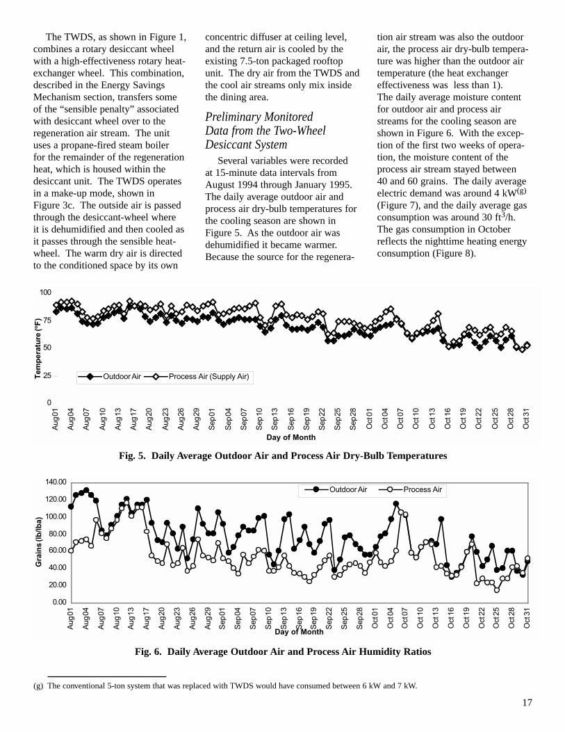
Preliminary Monitored Data from the Two-WheelDesiccant System
Several variables were recorded at 15-minute data intervals fromAugust 1994 through January 1995.The daily average outdoor air andprocess air dry-bulb temperatures forthe cooling season are shown inFigure 5. As the outdoor air wasdehumidified it became warmer.Because the source for the regenera-
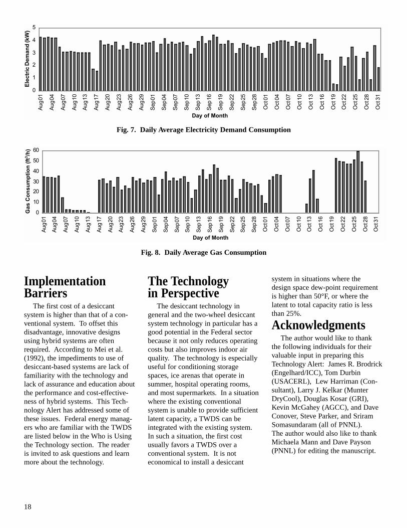
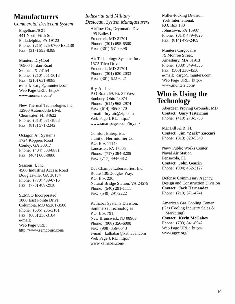
tion air stream was also the outdoorair, the process air dry-bulb tempera-ture was higher than the outdoor airtemperature (the heat exchangereffectiveness was less than 1). The daily average moisture contentfor outdoor air and process airstreams for the cooling season areshown in Figure 6. With the excep-tion of the first two weeks of opera-tion, the moisture content of theprocess air stream stayed between 40 and 60 grains. The daily averageelectric demand was around 4 kW(g)
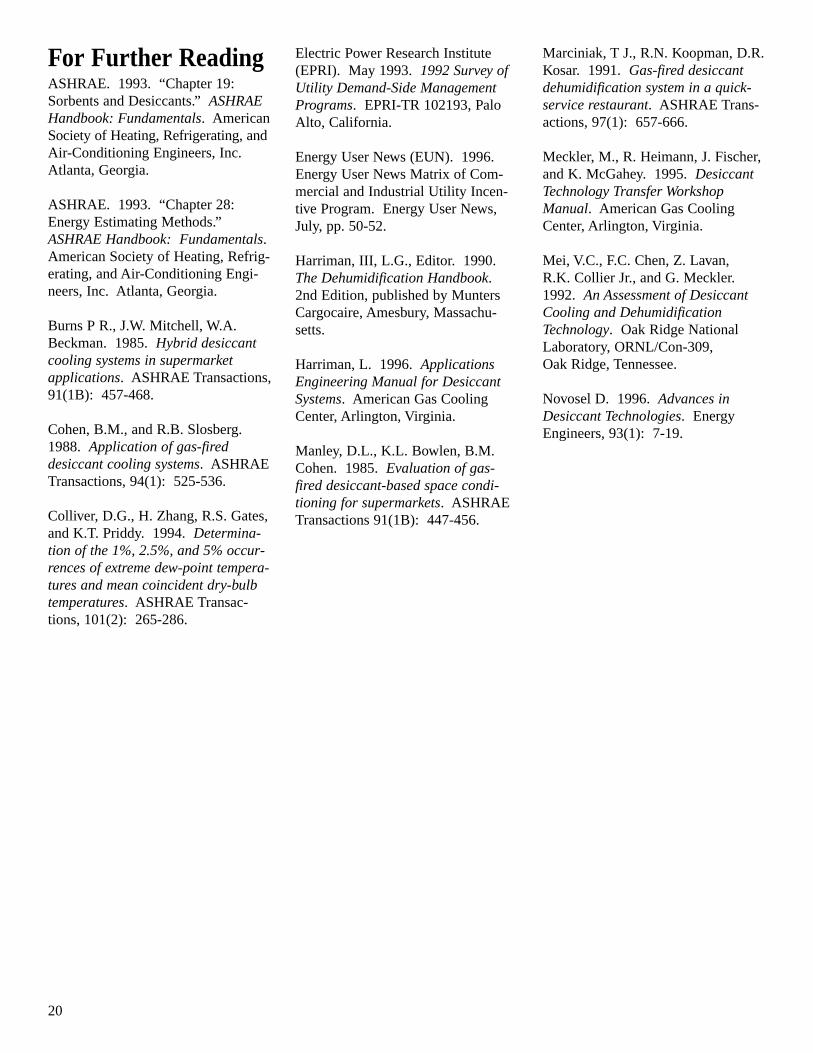
(Figure 7), and the daily average gasconsumption was around 30 ft3/h.The gas consumption in Octoberreflects the nighttime heating energyconsumption (Figure 8).
(g) The conventional 5-ton system that was replaced with TWDS would have consumed between 6 kW and 7 kW.
Fig. 6. Daily Average Outdoor Air and Process Air Humidity Ratios
0
25
50
75
100
Aug
01
Aug
04
Aug
07
Aug
10
Aug
13
Aug
17
Aug
20
Aug
23
Aug
26
Aug
29
Sep
01
Sep
04
Sep
07
Sep
10
Sep
13
Sep
16
Sep
19
Sep
22
Sep
25
Sep
28
Oct
01
Oct
04
Oct
07
Oct
10
Oct
13
Oct
16
Oct
19
Oct
22
Oct
25
Oct
28
Oct
31
Day of Month
Tem
per
atu
re (o
F)
Outdoor Air Process Air (Supply Air)
Fig. 5. Daily Average Outdoor Air and Process Air Dry-Bulb Temperatures
0.00
20.00
40.00
60.00
80.00
100.00
120.00
140.00
Aug
01
Aug
04
Aug
07
Aug
10
Aug
13
Aug
17
Aug
20
Aug
23
Aug
26
Aug
29
Sep
01
Sep
04
Sep
07
Sep
10
Sep
13
Sep
16
Sep
19
Sep
22
Sep
25
Sep
28
Oct
01
Oct
04
Oct
07
Oct
10
Oct
13
Oct
16
Oct
19
Oct
22
Oct
25
Oct
28
Oct
31
Day of Month
Gra
ins
(lb/lb
a)
Outdoor Air Process Air
18
ImplementationBarriers
The first cost of a desiccant system is higher than that of a con-ventional system. To offset this disadvantage, innovative designsusing hybrid systems are oftenrequired. According to Mei et al.(1992), the impediments to use ofdesiccant-based systems are lack offamiliarity with the technology andlack of assurance and education aboutthe performance and cost-effective-ness of hybrid systems. This Tech-nology Alert has addressed some ofthese issues. Federal energy manag-ers who are familiar with the TWDSare listed below in the Who is Usingthe Technology section. The reader is invited to ask questions and learnmore about the technology.
The Technology in Perspective
The desiccant technology in general and the two-wheel desiccantsystem technology in particular has agood potential in the Federal sectorbecause it not only reduces operatingcosts but also improves indoor airquality. The technology is especiallyuseful for conditioning storagespaces, ice arenas that operate insummer, hospital operating rooms,and most supermarkets. In a situationwhere the existing conventional system is unable to provide sufficientlatent capacity, a TWDS can be integrated with the existing system.In such a situation, the first cost usually favors a TWDS over a conventional system. It is not economical to install a desiccant
system in situations where the design space dew-point requirementis higher than 50°F, or where thelatent to total capacity ratio is lessthan 25%.
AcknowledgmentsThe author would like to thank
the following individuals for theirvaluable input in preparing this Technology Alert: James R. Brodrick(Engelhard/ICC), Tom Durbin(USACERL), Lew Harriman (Con-sultant), Larry J. Kelkar (MunterDryCool), Douglas Kosar (GRI),Kevin McGahey (AGCC), and DaveConover, Steve Parker, and SriramSomasundaram (all of PNNL). The author would also like to thankMichaela Mann and Dave Payson(PNNL) for editing the manuscript.
Fig. 7. Daily Average Electricity Demand Consumption
Fig. 8. Daily Average Gas Consumption
0
1
2
3
4
5
Aug
01
Aug
04
Aug
07
Aug
10
Aug
13
Aug
17
Aug
20
Aug
23
Aug
26
Aug
29
Sep
01
Sep
04
Sep
07
Sep
10
Sep
13
Sep
16
Sep
19
Sep
22
Sep
25
Sep
28
Oct
01
Oct
04
Oct
07
Oct
10
Oct
13
Oct
16
Oct
19
Oct
22
Oct
25
Oct
28
Oct
31
Day of Month
Ele
ctri
c D
eman
d (k
W)
0
10
20
30
40
50
60
Aug
01
Aug
04
Aug
07
Aug
10
Aug
13
Aug
17
Aug
20
Aug
23
Aug
26
Aug
29
Sep
01
Sep
04
Sep
07
Sep
10
Sep
13
Sep
16
Sep
19
Sep
22
Sep
25
Sep
28
Oct
01
Oct
04
Oct
07
Oct
10
Oct
13
Oct
16
Oct
19
Oct
22
Oct
25
Oct
28
Oct
31
Day of Month
Gas
Co
nsu
mp
tio
n (
ft3/h
)
19
ManufacturersCommercial Desiccant System
Engelhard/ICC441 North Fifth St.Philadelphia, PA 19123Phone: (215) 625-0700 Ext.130Fax: (215) 592-8299
Munters Cargocaire79 Monroe Street,Amesbury, MA 01913Phone: (888) 349-4335Fax: (500) 338-4556 e-mail: [email protected] Page URL: http://www.munters.com/
Who is Using theTechnology
Aberdeen Proving Grounds, MDContact: Gary TestermanPhone: (410) 278-5738
MacDill AFB, FLContact: Jim “Zack” ZaccariPhone: (813) 828-5340
Navy Public Works Center,Naval Air StationPensacola, FLContact: John GeurinPhone: (904) 452-3127
Defense Commissary Agency,Design and Construction DivisionContact: Jack HernandezPhone: (210) 671-4741
American Gas Cooling Center(Gas Cooling Industry Sales &
Marketing)Contact: Kevin McGaheyPhone: (703) 841-8542Web Page URL: http://www.agcc.org/
20
For Further ReadingASHRAE. 1993. “Chapter 19:Sorbents and Desiccants.” ASHRAEHandbook: Fundamentals. AmericanSociety of Heating, Refrigerating, andAir-Conditioning Engineers, Inc.Atlanta, Georgia.
ASHRAE. 1993. “Chapter 28:Energy Estimating Methods.”ASHRAE Handbook: Fundamentals.American Society of Heating, Refrig-erating, and Air-Conditioning Engi-neers, Inc. Atlanta, Georgia.
Burns P R., J.W. Mitchell, W.A.Beckman. 1985. Hybrid desiccantcooling systems in supermarketapplications. ASHRAE Transactions,91(1B): 457-468.
Cohen, B.M., and R.B. Slosberg.1988. Application of gas-fired desiccant cooling systems. ASHRAETransactions, 94(1): 525-536.
Colliver, D.G., H. Zhang, R.S. Gates,and K.T. Priddy. 1994. Determina-tion of the 1%, 2.5%, and 5% occur-rences of extreme dew-point tempera-tures and mean coincident dry-bulbtemperatures. ASHRAE Transac-tions, 101(2): 265-286.
Electric Power Research Institute(EPRI). May 1993. 1992 Survey ofUtility Demand-Side ManagementPrograms. EPRI-TR 102193, PaloAlto, California.
Energy User News (EUN). 1996.Energy User News Matrix of Com-mercial and Industrial Utility Incen-tive Program. Energy User News,July, pp. 50-52.
Harriman, III, L.G., Editor. 1990.The Dehumidification Handbook.2nd Edition, published by MuntersCargocaire, Amesbury, Massachu-setts.
Harriman, L. 1996. ApplicationsEngineering Manual for DesiccantSystems. American Gas CoolingCenter, Arlington, Virginia.
Manley, D.L., K.L. Bowlen, B.M.Cohen. 1985. Evaluation of gas-fired desiccant-based space condi-tioning for supermarkets. ASHRAETransactions 91(1B): 447-456.
Marciniak, T J., R.N. Koopman, D.R.Kosar. 1991. Gas-fired desiccantdehumidification system in a quick-service restaurant. ASHRAE Trans-actions, 97(1): 657-666.
Meckler, M., R. Heimann, J. Fischer,and K. McGahey. 1995. DesiccantTechnology Transfer WorkshopManual. American Gas CoolingCenter, Arlington, Virginia.
Mei, V.C., F.C. Chen, Z. Lavan,R.K. Collier Jr., and G. Meckler.1992. An Assessment of DesiccantCooling and DehumidificationTechnology. Oak Ridge NationalLaboratory, ORNL/Con-309,Oak Ridge, Tennessee.
Novosel D. 1996. Advances inDesiccant Technologies. EnergyEngineers, 93(1): 7-19.
The Federal Government is the largest energy consumer in the nation. Annually, in its 500,000 buildings and 8,000 locations worldwide,it uses nearly two quadrillion Btu (quads) of energy, costing over $8 billion. This represents 2.5% of all primary energy consumption inthe United States. The Federal Energy Management Program was established in 1974 to provide direction, guidance, and assistance toFederal agencies in planning and implementing energy management programs that will improve the energy efficiency and fuel flexibilityof the Federal infrastructure.
Over the years several Federal laws and Executive Orders have shaped FEMP's mission. These include the Energy Policy and Conserva-tion Act of 1975; the National Energy Conservation and Policy Act of 1978; the Federal Energy Management Improvement Act of 1988;and, most recently, Executive Order 12759 in 1991, the National Energy Policy Act of 1992 (EPACT), and Executive Order 12902 in1994.
FEMP is currently involved in a wide range of energy-assessment activities, including conducting New Technology Demonstrations, tohasten the penetration of energy-efficient technologies into the Federal marketplace.
Federal Energy Management Program
About the Federal Technology AlertsThe Energy Policy Act of 1992, and
subsequent Executive Orders, mandatethat energy consumption in the Federalsector be reduced by 30% from 1985levels by the year 2005. To achievethis goal, the U.S. Department ofEnergy’s Federal Energy ManagementProgram (FEMP) is sponsoring a series of programs to reduce energyconsumption at Federal installationsnationwide. One of these programs,the New Technology DemonstrationProgram (NTDP), is tasked to acceler-ate the introduction of energy-efficientand renewable technologies into theFederal sector and to improve the rateof technology transfer.
As part of this effort FEMP is sponsoring a series of Federal Tech-nology Alerts (FTAs) that provide summary information on candidateenergy-saving technologies developedand manufactured in the United States.The technologies featured in theTechnology Alerts have already entered the market and have someexperience but are not in general use in the Federal sector. Based on theirpotential for energy, cost, and environ-mental benefits to the Federal sector,the technologies are considered to be
leading candidates for immediateFederal application.
The goal of the Technology Alerts is to improve the rate of technologytransfer of new energy-saving tech-nologies within the Federal sector andto provide the right people in the fieldwith accurate, up-to-date informationon the new technologies so that theycan make educated judgments onwhether the technologies are suitablefor their Federal sites.
Because the Technology Alerts arecost-effective and timely to produce(compared with awaiting the results of field demonstrations), they meet the short-term need of disseminatinginformation to a target audience in a timeframe that allows the rapiddeployment of the technologies—andultimately the saving of energy in theFederal sector.
The information in the TechnologyAlerts typically includes a descriptionof the candidate technology; the results of its screening tests; a descrip-tion of its performance, applicationsand field experience to date; a list ofpotential suppliers; and important contact information. Attached
appendixes provide supplemental information and example worksheetson the technology.
FEMP sponsors publication of theFederal Technology Alerts to facilitateinformation-sharing between manufac-turers and government staff. While the technology featured promises sig-nificant Federal-sector savings, theTechnology Alerts do not constituteFEMP’s endorsement of a particularproduct, as FEMP has not indepen-dently verified performance data provided by manufacturers. Nor do the Federal Technology Alerts attemptto chart market activity vis-a-vis thetechnology featured. Readers shouldnote the publication date on the backcover, and consider the Alert as anaccurate picture of the technology andits performance at the time of publica-tion. Product innovations and theentrance of new manufacturers or suppliers should be anticipated sincethe date of publication. FEMP encourages interested Federal energyand facility managers to contact themanufacturers and other Federal sitesdirectly, and to use the worksheets inthe Technology Alerts to aid in theirpurchasing decisions.
This report was sponsored by the United States Government. Neither the United States nor any agency or contractor thereof, nor any oftheir employees, makes any warranty, express or implied, or assumes any legal liability or responsibility for the accuracy, completeness,or usefulness of any information, apparatus, product, or process disclosed, or represents that its use would not infringe privately ownedrights. Reference herein to any specific commercial product, process, or service by trade name, mark, manufacturer, or otherwise, doesnot necessarily constitute or imply its endorsement, recommendation, or favoring by the United States Government or any agency orcontractor thereof. The views and opinions of authors expressed herein do not necessarily state or reflect those of the United StatesGovernment or any agency or contractor thereof.
For More Information
FEMP Help Desk(800) 363-3732International callers please use (703) 287-8391Web site: http://www.eren.doe.gov/femp/
General Contacts
Ted CollinsNew Technology Demonstration Program Program ManagerFederal Energy Management ProgramU.S. Department of Energy1000 Independence Avenue, SW, EE-92Washington, DC 20585(202) 586-8017Fax: (202) [email protected]
Steven A. ParkerPacific Northwest National LaboratoryP.O. Box 999, MSIN: K5-08Richland, Washington 99352(509) 375-6366Fax: (509) [email protected]
Produced for the U.S. Departmentof Energy by the Pacific Northwest National Laboratory