Page 1
Highway IDEA Program
Advanced Methods for Mobile Retroreflectivity Measurement of Pavement
Marking
Final Report for Highway IDEA Project 146
Prepared by:
Terry Lee, Leetron Vision, Concord, NH
July 2011
Page 2
INNOVATIONS DESERVING EXPLORATORY ANALYSIS (IDEA)
PROGRAMS MANAGED BY THE TRANSPORTATION RESEARCH BOARD
(TRB)
This NCHRP-IDEA investigation was completed as part of the National Cooperative Highway
Research Program (NCHRP). The NCHRP-IDEA program is one of the IDEA programs managed by
the Transportation Research Board (TRB) to foster innovations in highway and intermodal surface transportation systems. The other currently active IDEA programs are Transit -IDEA, which focuses
on products and results for transit practice in support of the Transit Cooperative Research Program
(TCRP) and Safety-IDEA which focuses on motor carrier and railroad safety practice in support of the
Federal Motor Carrier Safety Administration and Federal Railroad Administration. All these IDEA
program areas are integrated to promote the development and testing of nontraditional and innovative
concepts, methods, and technologies for surface transportation systems.
For information on the IDEA Program contact IDEA Program, Transportation Research Board, 500 5th
Street, N.W., Washington, D.C. 20001 (phone: 202/334-1461, fax: 202/334-2081,
http://www.nationalacademies.org/trb/idea)
The project that is the subject of this contractor-authored report was a part of the Innovations
Deserving Exploratory Analysis (IDEA) Programs, which are managed by the Transportation
Research Board (TRB) with the approval of the Governing Board of the National Research
Council. The members of the oversight committee that monitored the project and reviewed the
report were chosen for their special competencies and with regard for appropriate balance. The
views expressed in this report are those of the contractor who conducted the investigation
documented in this report and do not necessarily reflect those of the Transportation Research
Board, the National Research Council, or the sponsors of the IDEA Programs. This document
has not been edited by TRB.
The Transportation Research Board of the National Academies, the National Research Council,
and the organizations that sponsor the IDEA Programs do not endorse products or
manufacturers. Trade or manufacturers' names appear herein solely because they are considered
essential to the object of the investigation.
Page 3
NCHRP IDEA PROGRAM COMMITTEE CHAIR SANDRA Q. LARSON
IOWA DOT
MEMBERS
GARY A. FREDERICK
New York State DOT
GEORGENE GEARY
Georgia DOT
JOE MAHONEY
University of Washington
MICHAEL MILES
California DOT
TOMMY NANTUNG
Indiana DOT
VALERIE SHUMAN
Shuman Consulting Group LLC
JAMES SIME
Connecticut DOT (Retired)
L. DAVID SUITS
North American Geosynthetics Society
FHWA LIAISON DAVID KUEHN
Federal Highway Administration
TRB LIAISON RICHARD CUNARD
Transportation Research Board
COOPERATIVE RESEARCH PROGRAM STAFF CRAWFORD F. JENCKS
Deputy Director, Cooperative Research Programs
IDEA PROGRAMS STAFF
STEPHEN R. GODWIN
Director for Studies and Special Programs
JON M. WILLIAMS
Program Director, IDEA and Synthesis Studies
INAM JAWED
Senior Program Officer
DEMISHA WILLIAMS
Senior Program Assistant
EXPERT REVIEW PANEL
JAMES M. SIME, Connecticut DOT (Retired)
DAVID R. LUHR, Wisconsin DOT
BRADLEY J. OVERTURF, Connecticut DOT
PAUL J. CARLSON, Texas Transportation Institute
GREG SCHERTZ, Federal Highway Administration
SCOTT LESLIE, New Hampshire DOT
Page 4
Advanced Methods for Mobile Retroreflectivity Measurement of Pavement Marking Page 2
Advanced Methods for Mobile Retroreflectivity Measurement of Pavement
Marking
IDEA PROJECT FINAL REPORT
Contract Number NCHRP-IDEA Project 146
Prepared for the IDEA Program
Transportation Research Board
National Research Council
Terry Lee
Leetron Vision, Concord, NH
July 2011
Page 5
Advanced Methods for Mobile Retroreflectivity Measurement of Pavement Marking Page 3
Table of Contents
ACKNOWLEDGEMENTS ................................................................................................................. 4
1 Executive Summary ..................................................................................................................... 5
2 Body .............................................................................................................................................. 6
2.1 IDEA Product ........................................................................................................................ 6
2.2 Concept and Innovation ........................................................................................................ 6
2.3 Investigation........................................................................................................................... 7
2.3.1 Background .................................................................................................................... 7
2.3.2 Issues associated with the existing MUR ..................................................................... 9
2.3.3 Relationship between vehicle movements to retro light intensity ............................ 10
2.3.4 Solution......................................................................................................................... 13
2.3.5 Tracking System .......................................................................................................... 13
2.3.6 Imaging System ........................................................................................................... 14
2.3.7 Calibration System ....................................................................................................... 14
2.3.8 Temperature Control .................................................................................................... 15
2.3.9 Results .......................................................................................................................... 15
2.4 Plans for Implementation .................................................................................................... 18
3 Conclusions................................................................................................................................. 18
4 Appendix A: Cost saving on repainting budget Estimate ........................................................ 19
Page 6
Advanced Methods for Mobile Retroreflectivity Measurement of Pavement Marking Page 4
ACKNOWLEDGEMENTS
This project was conducted in cooperation with the Center for Transportation Research and
Education, Connecticut Department of Transportation and New Hampshire Department of
Transportation. The authors wish to acknowledge the following individuals. Without their insight
and assistance it would not have been possible to successfully complete of this research project.
• James M. Sime, P.E., ConnDOT, Manager of Research (retired);
• Mr. Bradley J. Overturf, ConnDOT, Division of Research, Transportation Photolog
Supervisor; • Robert Kasica, Conn. DOT, Data Collection Specialist;
• Vittorio P. Castro, ConnDOT,
• Scott Leslie, NH DOT, Data Collection Supervisor;
• Glenn E. Roberts, P.E., NH DOT, Chief of Research;
• Tobey, Reynolds, NH DOT, Senior Engineer;
• Eric Healey, NH DOT, Pavement Marking Supervisor;
• Robert Havey, NH DOT, Pavement Marking Foreman II;
• Charles Holzschuher, P.E. FDOT, Pavement Performance Engineer;
• Omar Smadi, Center for Transportation Research and Education, Ph.D., Research
Scientist,
• Paul J. Carlson, Ph.D., P.E., Texas Transportation Institute, Division Head of the
Operations and Design Division;
• Greg Schertz, P.E., FHWA, Retroreflectivity Team Leader,
• Inam Jawed, NCHRP-IDEA Program, Program Manager
• David R. Luhr Ph.D., WSDOT, Pavement Management Engineer,
• Jon Jackels, Minnesota DOT, ITS Program Engineer
• George Fearnley, SCORE Counselor
Page 7
Advanced Methods for Mobile Retroreflectivity Measurement of Pavement Marking Page 5
1 Executive Summary
To meet new Minimum Retro-Reflectivity Standards proposed by FHWA, State departments of
transportation (DOTs) face a need for new ways to manage the maintenance of pavement
markings. At the same time, most DOTs are experiencing reductions in resources, both in
staffing levels and in their maintenance budgets. The Leetron innovation described herein offers
a reliable solution to meet the new Retro-Reflectivity Standards and with fact-based condition
data on retroreflectivity, as well as enabling DOTs to achieve cost savings in their pavement
marking maintenance operations.
The objective of this project was to develop and demonstrate the use of a prototype mobile unit
for rapid and reliable measurement of marked pavement reflectivity. This final report describes
the results of efforts to design, build, and test a system to fulfill the requirements of this task.
The Leetron Mobile Retro-reflectometer Unit (MRU) is designed to address shortcomings of
traditional handheld and MRU systems, primarily shortcomings in the handling of motion issues
inherent in the mobile measurement process. The Leetron MRU invention provides an innovative
method of tracking measurements in real time that mitigates the effects of road vibration and
surface roughness. The Leetron method aims a laser at the center of the pavement marking and
uses a feedback loop to readjust the aim point as the vehicle travels at highway speeds. Leetron
researchers examined whether the new Leetron design would achieve a significant measurable
improvement over other existing methods.
After research, conceptualization, and design, a prototype mobile unit was built and tested. The
initial road test results demonstrated very good repeatability in the measurement parameters
acquired under real time mobile conditions. This observation was made from an analysis of test
results from June 2011. Note that the repeatability is in the range of 4% to 9%. Subsequent
improvements and alterations in the tracking system resulted in repeatability improvements
reaching a repeatability range of 1.5%. We feel that these results validate the basic technologies
used in the Leetron MRU system. We are pleased to submit this evidence as proof of the
expectations of many of the contributors and experts who are familiar with the concept and
agreed early on as to the robustness of the principals involved, yet had some doubts about the
practical application of these ideas.
Thanks to the NCHRP-IDEA program, we believe we have established proof of principle for our
mobile system. Once we complete the last phase of testing and refinements early in 2012, we
anticipate presenting a fait accompli of the Leetron MRU system that will set a new standard for
mobile retro-reflectivity measurement, providing an accurate, repeatable and reliable machine
and methodology that will benefit FHWA and State DOTs, and the motoring public they serve.
Page 8
Advanced Methods for Mobile Retroreflectivity Measurement of Pavement Marking Page 6
2 Body
2.1 IDEA Product
The product resulting from this
research is a vehicle-mounted system
for retro-reflectivity measurement on
pavement marking.
Figure 1 shows a prototype unit. The
system will meet the performance
requirements of accuracy,
repeatability, and reproducibility. Those
variations are anticipated to be less than
10%. The system should be stable. It
should be able to operate under a variety of road and environmental conditions, requiring only a
simple daily verification procedure. This is a marked improvement over current competing
MRU systems that require hourly calibration. And, as an additional benefit, only a single
operator is required, as opposed to two personnel usually required by the existing competing
MRU technology. We must also mention that this system is fully capable of simultaneously
measuring two lanes of markings instead of one. In summary, the system is anticipated to
provide accurate, stable, reliable, efficient, and simple operation, thereby providing a new level
of cost effectiveness in the field of vehicle-mounted pavement retro-reflectivity measurement.
2.2 Concept and Innovation
Retro-reflectivity is a measure of how efficiently
the pavement marking returns
(reflects) light from the vehicle headlamps back to
the driver as shown in Figure 2. To measure
pavement marking retro-reflectivity, an international
standard is recognized by the State DOTs and the
FHWA, which uses “Standard 30 Meter
Geometry” (see figures 3 below).
For manual system, small battery-powered hand-
held devices with 30-meter geometry are placed
on the pavement and readings are taken at spot
locations by a technician. A mobile system
introduces additional factors and conditions that
will impact the measurements acquired by these
devices. Four of those conditions with the greatest
Figure 2 Retro-reflectivity concepts
Figure 1 Leetron Mobile Unit hardware configuration overview
Figure 3 Standard 30 Meter Geometry
Page 9
Advanced Methods for Mobile Retroreflectivity Measurement of Pavement Marking Page 7
impacts are sunlight, vehicle dynamics, road profile and temperature.
Sunlight introduces variations in light levels that affect the projected light source of the retro-
reflectivity measurement device. Vehicle dynamics (pitch, roll and yaw) affect the location
where the light source meets the pavement marking and the target location where the imaging
device is measuring. Road profile (vertical variations between wheel path and marking) also
“moves” the light source and image device and impact targeting capabilities. Also, components
of the light source and imaging device are typically temperature sensitive, where variations in air
temperature affect measurements. Traditional MRU units use many methods to compensate for
and overcome the influence of sunlight and temperature, but available MRU devices have been
lacking in solid solutions that must dealing with the motion issues and road profiles in mobile
units.
The proposed IDEA innovation leverages the latest proven technologies available today to
provide a more comprehensive solution to all of the issues mentioned. The Leetron MRU device
is relatively simple to understand - you point a laser light on to the pavement marking and keep it
there with automated aiming-correction techniques built into the system, while the vehicle
travels at highway speeds. With the laser staying on target pavement markings regardless of
external motion influences, the system does not have to deal with the variations introduced by
vehicle motion and road profile. Although easily stated, the actual implementation of the concept
is complex and a key achievement of this IDEA project. The engineering challenge was to
develop a robust real time tracking system that provides automated aiming-correction
capabilities. For the reader not familiar with the principals involved, you have only to visualize
the tracking system available to a fighter jet pilot. You no doubt have seen images on TV or in
the movies (think Top Gun) of such a system locking on a target via computer adjusted radar and
sensor tracking. The computer implements a feedback system that integrates the various
changing parameters to track the target. In some ways, the roadway challenges we faced to make
our reflectivity measurements were just as difficult, given the need for simplicity and cost
constraints and the addition of such issues as vehicle-speed changes, low light-source projection
angle (1.24 degrees) and variability of environmental conditions.
2.3 Investigation
2.3.1 Background
Being able to accurately and efficiently measure the retro-reflective condition of traffic control
devices is becoming increasingly important for all agencies in the U.S. responsible for
maintaining roads open to public travel. To guarantee a safer driving environment, the FHWA is
establishing minimum retro-reflective maintenance levels for signs and pavement markings. The
requirements for signs have been established and published in the MUTCD. The FHWA has
completed their research on pavement markings maintenance retro-reflectivity levels and has
begun to implement official rules for markings in 2009 to establish national minimum
maintenance standards in the MUTCD.
Measuring retro-reflectivity of pavement markings utilizing a MRU is anticipated to be not only
the most efficient method, but also the safest work environment for both technicians and
Page 10
Advanced Methods for Mobile Retroreflectivity Measurement of Pavement Marking Page 8
motorists. See Table 1 and consider the issues faced by a worker walking along a public
roadway to take manual hand-held retro-reflectivity meter readings. Currently in the U.S., there
is only one competing mobile technology providing MRU capabilities. The new innovative
Leetron MRU technology described in this IDEA project has the potential to deliver
improvements in safety efficiency, accuracy, and repeatability.
Table 1 Pavement Marking Retroreflectivity Measurement Methods
Pavement Marking
Retro reflective
Method
Safe? Efficient? Accurate? Repeatable?
Visual Inspection N N N N
Hand-Held Device N N Y Y
Current MRU Y Y N N
Innovative MRU Y Y TBD Y
Successful field implementation of this system will provide these improved qualities to
transportation agencies desiring to realize the advantages. Theoretically, better management of
pavement marking retro-reflectivity will lead to safer nighttime roadways and safer driving
conditions for all, with particular advantages for older drivers with night impaired vision.
Without a doubt, the Leetron MRUs will lead to safer measurement conditions and produce rich
data sources for analysis such as life cycle costs, QC reporting, and contractor compliance with
warranty and performance-based contracts.
Measuring the many miles of pavement markings is difficult to do cost effectively using
handheld retro-reflectivity meters, but is an objective measurement. Some DOTs will elect to
use statistical sampling strategies with handheld meters. In an environment that is stressing
operating cost minimization in government, manual methods are likely to be too expensive,
especially considering that pavement markings will need to be measured annually in most cases.
Visual inspections are subjective and inherently inaccurate, with repeatability problems, making
a poor choice for DOTs that need to enforce performance guarantees and warrantees. As stated
previously, the existing MRU is not sufficiently practical due to its inherent design limitations
that have just begun to surface with increased usage. 1,2
One major consideration always at the top of any civil organization’s agenda is the potential for
savings that could be realized by changing pavement-markings repainting schedules. Currently,
many agencies assign a road a fixed repainting schedule based on factors such as traffic load,
prevailing weather conditions, and the type of pavement markings. Some roads have bi-annual
1 Pike, A. Evaluating Factors that may Influence the Accuracy of Mobile Retroreflectivity Data Collection. Paper
09-0493, TRB Annual Meeting, January 2009.
2 Fletcher, J. et al. Characteristics of a Calibration Standard for the Mobile Retroreflectometer Unit, TRB Annual
Meeting, January 2009.
Page 11
Advanced Methods for Mobile Retroreflectivity Measurement of Pavement Marking Page 9
paint schedules, while others may see years of service between repainting. Generally, these fixed
schedules are based on worst-case scenarios in order to guarantee compliance with minimum
retro-reflectivity requirements. With the availability of real time retro-reflectivity data from the
Leetron MRU, the roads that fall below the minimum requirement could be queued up for
painting based on a priority schedule. Action on roads measured and shown to be in compliance
with the required safety standards could be delayed in the repainting schedule. Such an
arrangement has the potential to result in a safer environment and make for more effective use of
available maintenance repainting budgets. Our preliminary study of the potential for repainting
savings estimates that savings should be in the range of 5 to 20%. Appendix A details our
calculation methodology for estimating cost savings in repainting budgets. Recent research from
Kentucky 3 shows that it is not necessary to re-stripe many roads annually. The report indicates that
nearly half of those striped had passing levels after two years. That represents a 25% potential savings of repainting costs if DOTs can identify with confidence those line stripes that do not need repainting. Considering that the annual US DOT pavement markings expenditures have been estimated to be approximately $1billion dollars, the potential for savings with the Leetron MRU device and adjustments
to maintenance management methodologies are quite significant.4
2.3.2 Issues associated with the existing MUR
In the field of vehicle-mounted pavement retro-reflectivity measurement, our investigation began
with an examination of issues associated with the only MRU system currently available. The list
of issues we identified is summarized as follows:
1. MRU relies heavily on the level of experience and skill of users to collect reasonable
data, thus the process is subjective.
2. Many user calibrations (up to 30 times a day) are required to minimize system
sensitivities.
3. It is imperative that the vehicle load is kept as constant as possible during the process of
data collection. Changes in the weight distribution within the vehicle cause a change in
the measurement geometry. Therefore, operators must ensure that they and equipment
remain in their original place/position during data collection. It isn’t clear what the
impact of fuel usage is on changes in weight distribution. 5
4. In some areas, it can be time consuming to find a flat section of roadway for required
system calibrations, which may reduce operator productivity. Flat sections of roadway
are needed to ensure proper geometry for the calibration procedure.6
3 Eric R. Green, Kenneth R. Agent. Evaluation of Pavement Marking Performance.
www.ktc.uky.edu/Reports/KTC_08_21_SPR_330_07_2I.pdf
4 Carlson, P.J., E.S. Park, and C.K. Andersen. The Benefits of Pavement Markings: A Renewed Perspective Based
On Recent and Ongoing Research. Pending Publication in Transportation Research Record series. Washington,
D.C., March 2009.
5 Robert J. Benz, P.E. MOBILE RETROREFLECTIVITY BEST PRACTICES HANDBOOK.
http://tti.tamu.edu/documents/0-5656-P1.pdf.
6 Charles Holzschuher. Mobile Retroreflectivity Testing for a Pavement Marking Management
System. http://www.dot.state.fl.us/Structures/DesignConf2006/Presentations/session52/Final-52Holzschuher.pdf
Page 12
Advanced Methods for Mobile Retroreflectivity Measurement of Pavement Marking Page 10
5. Some studies have observed retro-reflectivity measurement variation can be as much as
20% lower while in motion as opposed to those same measurements taken while
stationary.
6. When roads are not being completely flat, changes in surface elevation affect the
measurement.
7. The MRU system produces results that are temperature sensitive. The sensor, laser, and
interference filter all appear contribute to the temperature sensitivity problem.
It’s obvious that the existing system is unstable. It also shows that any height variation on the
system has a large impact on measurement accuracy. To understand this impact, we examined
the relationship between vehicle movements to retro-reflectivity measurement.
2.3.3 Relationship between vehicle movements to retro light intensity
In the following section, we examined the expected light intensity variations caused by vibration,
tilt and road profile. Figure
5 illustrate the scenario where motion from the vehicle causes the device to lift and tilt. Also, the
scenario when road profile is lower. Table 2 shows the calculations for light intensity variation.
Lifts
In the case of lifts caused by typical bounces on a vehicle
as it travels, a 10mm bounce “up” causes the light source to
point at a location 460 mm further away from the vehicle.
Based on the inverse square law (see figure 4 on the left)
for light intensity verses distance the light intensity at the
intersection point is calculated to be 8.6% lower(see lifts in
Figure 5 and table 2). The same amount of distance-
related light-intensity variation applies when the light
reflects back to the imaging sensor (camera). Therefore
the total light intensity is expected is to be twice this
value or 17.2% lower.
Tilt
Tilt represents a condition where the vehicle is not level relative to the road surface. In our
example, we assumed that the vehicle is tilted up by 0.05 degrees (the front moves up by 10 mm
while the back remains the same and this causes the tilt). Based on calculations similar to those
for the effect of lift, the 0.05 degrees of tilt causes the distance illuminated to be 880 mm further
away from the target area, and the total light intensity is expected to be 30% lower.
Road Profile
Since the wheel path and the pavement marking area are less than 2 feet away, we did not
initially expect height differences between the two areas. Practical application of the system soon
Figure 3 Light intensity verses distance.
As distance from the light source increase,
the light intensity decrease follows the
inverse square law.
Page 13
Advanced Methods for Mobile Retroreflectivity Measurement of Pavement Marking Page 11
showed a problem but investigation revealed the height difference was not the cause. We found
that the practice of “crowning” the road to facilitate runoff of water to the roadside was an issue.
To examine and accommodate this crowning effect, we assumed that the pavement marking area
is 10 mm lower than the wheel path area. The variations will be the same as a lift of 10 mm. The
light source is 460 mm further away which results in 17.2% lower light intensity.
The assumption used in this calculation is based on typical road conditions. On secondary roads
where the road is not as smooth, variations are expected to multiply. It is easy to conclude that
the combination of these three conditions have tremendous impacts on retro-reflectivity
measurements. Any MUR system will need to have a solution to solve these issues. Averaging
and defocusing are the two methods used on the existing systems. The averaging method does, as
you would expect, accumulates and averages a stream of measurement results. The assumption is
that the errors will average out over time. The defocusing method is based on defocusing the
image on the image sensor. With blurry images, the variation on light intensity created by the
variables is less pronounced. Both methods will lessen the variations, but without solving the
primary issue and with compromising of the accuracy of the results.
Table 2 Light intensity variation under geometry variation
Conditions Amount Unit
Distance to
Intersection
% of Light Intensity
variation at
intersection
% of Light
Intensity variation
at light sensor
Initial Mm 10,000
Lifts 10 Mm 10.462 -8.60% -17.20%
Tilted 0.05 Degree 10.88 -15.00% -30.00%
Lower
Profile 10 Mm 10.462 -8.60% -17.20%
Page 14
Advanced Methods for Mobile Retroreflectivity Measurement of Pavement Marking Page 12
Figure 5 Geometry variation effect on light intensity
Page 15
Advanced Methods for Mobile Retroreflectivity Measurement of Pavement Marking Page 13
2.3.4 Solution
It appeared to the Leetron design team that to build a stable system, a solution was needed to
compensate for the variations introduced by motion. Variability of the sensor position relative
to the target is unavoidable in practical driving conditions, being caused by the aforementioned
factors. All efforts to control and minimize motion will at best create only a marginal
improvement in variance. Even if the movement is controlled, the road profile variation will
still need to be addressed. Ergo, the solution developed by Leetron under this project is to point
the laser at the center of pavement marking and to continually adjust the aim to keep it on
target. As stated, by keeping the laser pointed at the same distance, the variables and their
effects on the measurements are minimized. As a result, the retro-reflectivity measurements are
independent of the motion and road profile variation. The question is whether it is possible to
keep the laser aimed at the marking center as the system travels at highway speed.
2.3.5 Tracking System
The difficulty is not in pointing the laser at the center of the pavement marking; the hard part is
keeping it there as the vehicle travels at highway speed. As is typical with any new engineering
ideas, at some point the inventors realize that full analytical investigation of a theory, regardless
of how promising it seems on paper, does not guarantee the expected results in the real world.
We knew that feasibility had to be determined by the execution of the idea. We therefore knew
we had to build and test the system on the road. To this end, Leetron built a system consisting of
the following...
1. A front unit consisting of a camera for location information.
2. A back unit consisting of a laser, image device and light path adjustment (re-aiming)
devices.
The sequence of events is as follows:
1. The Camera from the front unit identifies the location of pavement marking.
2. The Camera from the front unit identifies the location of the laser on the pavement.
3. The location information is used to determine the target location for the back unit and
calculates the adjustment needed to aim the laser at the target point on the pavement
marking.
4. The Laser from the back unit projects a laser onto the pavement marking.
5. The Light bounces back from the glass beads (imbedded in the pavement marking) to the
back unit.
6. The imaging device uses optical filtering to reject sunlight yet allows the laser light to
pass.
7. The image device measures the amount of light bouncing back.
8. A transformation system converts the light intensity to a retro-reflectivity value.
9. As the vehicle travels, the laser will not stay on the target (center of pavement marking)
due to one or a combination of the flowing factors: bounce on the road, sway from
driving and pavement profile variation, etc.
Page 16
Advanced Methods for Mobile Retroreflectivity Measurement of Pavement Marking Page 14
10. To keep the laser on target, the system repeats the steps between 1 and 9 to continually
re-aim the laser.
How well the Leetron MRU system performs is dependent on this critical tracking system. To
keep up with the sway and bounce at highway speed, the tracking system needs to be fast. We
determined that a cycle time of 80 cycles per second (80 Hz) would be fast enough to keep the
laser aimed at its target. This means that each cycle acquires an image, processes that image for
location information, calculates the needed movement to compensate for positional offset
resulting from motions and finally repositions the aim of the light source. With this fast cycle
time and robust movement control mechanism, our tracking system is performing above
expectations. At highway speed, the laser acquires the target and stays centered during the many
variable conditions. The Leetron MRU aiming system is to achieving successful performance
under real highway conditions.
2.3.6 Imaging System
A critically important component of the system is the
imaging hardware. This measures the light retro-reflectivity
from the pavement marking. The Leetron MRU imaging
system utilizes the latest technology components to provide
the continuous measurement input required. These
components can continuously capture lines at the rate of
2000 lines per second. At highway speeds, this high capture
rate allows the Leetron MRU to produce a continuous stream
of measurements at 15mm intervals. A way of visualizing
this is to think of drawing a continuous line along the center
of the pavement marking. This line would represent the area
the system is measuring for retro-reflectivity. Figure 6 on the
right illustrates the difference between the existing and the
proposed system. This continuous measurement is the basic
building block for accurate and repeatable retro-reflectivity
measurement.
2.3.7 Calibration System
One of the design goals for the Leetron system is to avoid the need for frequent calibrations. A
system requiring frequent calibration indicates that the measurement method is not stable. To
build a stable system, Leetron used comprehensive calibration procedures embodying thousands
of calibration points. These calibration points are used to provide a knowledge base that allows
the system to react to and handle various scenarios. The Leetron approach to system calibration
is to perform one comprehensive calibration during system installation instead of the hourly
calibrations of the competing MRU. When operating in the field, a simple daily procedure is
used to verify the system is working normally. Since it is not practical to calibrate thousands of
points manually, an automated calibration system was developed. The calibration system uses a
sample strip moved in horizontal and vertical directions during the process of calibration.
Figure 6 Measurement technique of Leetron MRU is on the right. Competitor's approach is on the left.
Page 17
Advanced Methods for Mobile Retroreflectivity Measurement of Pavement Marking Page 15
2.3.8 Temperature Control
Temperature control is another function that had to be accounted for in the system to achieve
stability. The design accommodates all sensitive electronic components in a stable temperature
environment. To keep the size of the back unit small, the system uses a temperature control unit
(heating/cooling) located remotely inside the van. Flexible ducting is used to transfer air to the
external units.
2.3.9 Results
The project was performed in two stages. Work in Stage 1 focused on designing and building a
prototype lab unit capable of measuring retro-reflectivity from sample strips and a calibration
system. Work in Stage 2 involved developing, assembling and testing the mobile retro-
reflectivity unit mounted on a vehicle.
Lab Unit (Stage 1)
The objective of the lab unit was to build the basic hardware and software structure and
demonstrate that the system was capable of retro-reflectivity measurement of pavement markings
in stationary mode and a controlled environment.
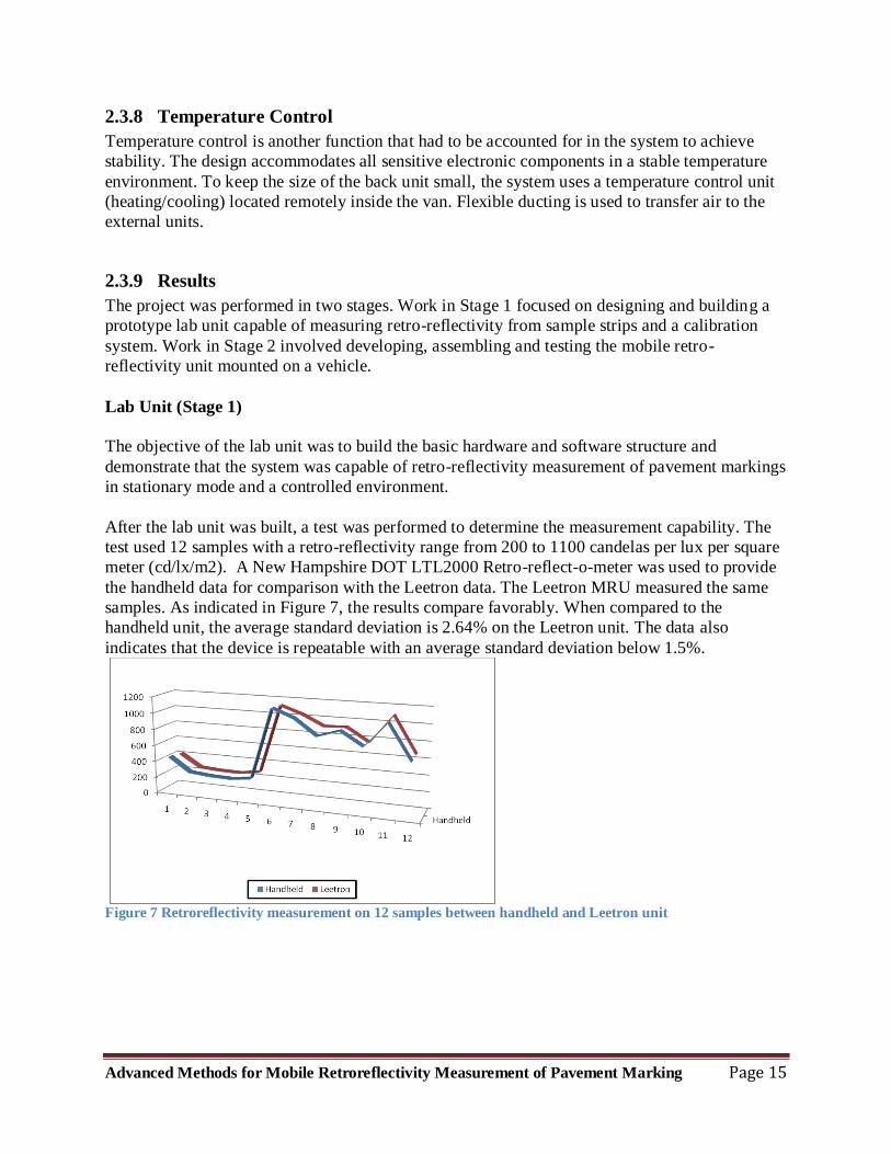
After the lab unit was built, a test was performed to determine the measurement capability. The
test used 12 samples with a retro-reflectivity range from 200 to 1100 candelas per lux per square
meter (cd/lx/m2). A New Hampshire DOT LTL2000 Retro-reflect-o-meter was used to provide
the handheld data for comparison with the Leetron data. The Leetron MRU measured the same
samples. As indicated in Figure 7, the results compare favorably. When compared to the
handheld unit, the average standard deviation is 2.64% on the Leetron unit. The data also
indicates that the device is repeatable with an average standard deviation below 1.5%.
Figure 7 Retroreflectivity measurement on 12 samples between handheld and Leetron unit
Page 18
Advanced Methods for Mobile Retroreflectivity Measurement of Pavement Marking Page 16
Mobile prototype Unit
(Stage 2)
The transition from lab unit
to mobile unit was more
complicated than
anticipated. First, we began
to discover and quantify the
effects of sunlight variation,
various other conditions on
pavement markings such as
wear, tire marks, cracks and
markings scraped off (by
snow plows), etc. This
created a better
understanding of the
challenges for the location
identification processes
(aiming). Second, the road
profile (vertical variation on
road) variations and the
attendant effects on the
system measurements were much
greater than what we initially
anticipated. We soon discovered the limitations of the lab unit design in a practical environment.
Leetron developed a totally new mobile-unit design incorporating and improving on the critical
tracking method.
Road Tests
The initial road test of this
new improved system was
performed in June 2011. It
consisted of measurements
taken at speeds of 40 MPH
and 60 MPH.
Figure 9 shows the result
from the 40 MPH road test.
Measurements were taken
along a one mile long track
and were reported at 0.1-
mile intervals. The road was
painted over 9 months ago.
It went through one snow
season. There are signs of
Figure 8 Leetron Prototype Mobile Unit.
Figure 4 Comparison between mobile and handheld on 40 MPH road
Page 19
Advanced Methods for Mobile Retroreflectivity Measurement of Pavement Marking Page 17
pavement marking paint scraped off by snowplows. The graph on the three runs indicated good
repeatability, and the standard deviation is 9%. The graph also shows that the measurement
corresponds well to manual measurements taken on the sites.
Figure 10 shows
the results from
the 60 MPH
road test. This
was taken along
a 3.5-mile
segment and
was reported at
0.1 mile
intervals.
Pavement
markings were
more than six
months old and
had experienced
one winter season. There
are signs of pavement
marking paint scraped off, presumably by snowplows. The graph on the two runs indicated good
repeatability at
4%.
Since the initial
road test, more
refinements have
been
implemented.
The latest road
test shows the
repeatability at
1.5% as
recorded in
Figure 11. At
this time, we do
not have the
comprehensive
data set to
indicate the system accuracy
on road test at this time.
However, initial accuracy test results indicate retro-reflectivity measurement results from
Leetron MRU are within the design expectation of 10% accuracy. At current view the final
accuracy for the system should be under 5%.
Figure 5 Repeatability Road Test at 60 MPH road
Figure 6 Repeatability Road Test at 60 MPH after refinements
Page 20
Advanced Methods for Mobile Retroreflectivity Measurement of Pavement Marking Page 18
2.4 Plans for Implementation
With the success of the prototype development and the success of the latest model of the system,
the project team is confident in the system’s ability to continue to improve and set new standards
for retro-reflectivity measurement. More engineering and financial resources are being employed
toward the commercialization of the unit. . Currently, a beta production version is being designed
and built incorporating design changes that provide a more robust solution and will handle a
wider variety of marking and environmental conditions. Components in the system have been
upgraded to higher performance products optimizing system reliability. Also, additional
functionalities will be added to accommodate the needs of a final production model. Once the
Leetron system is fully proven, the researchers will explore all the options for
commercialization. Since quality is the key to the success of this project, the team expects that
direct manufacturing and support would be the natural progression of events. To illustrate and
study the potential benefits of the system, the team is looking for opportunities to partner with
FHWA and state agencies on pilot projects. One avenue to help customers realize the benefit of
the new innovations without committing any capital investment would be to provide a data
collection service. The service would build on reliable and efficient data quality and data
collection. The team believes that a customer will be able to save sufficiently on repainting strips
while keeping American roads safer.
3 Conclusions
It goes without saying that in the current economic environment, there is no state agency that is
not interested in achieving savings. Where highway safety is concerned, resources have to be
allocated to satisfy federal requirements. The Leetron imaging system provides a faster, more
cost effective method and business plan to minimize expenditures without compromising safety
to satisfy the Federal requirements. It does so by providing a leap forward in the technology
used. Since Leetron MRU measure two lines in a single pass, as compared to one line per pass
with other MRUs, the measurement rate will be double. The field production rate of a Leetron
MRU is anticipated to be on average of 70% higher. Since the Leetron MRU does not require
hourly calibration, nor does it need to be relocated from side to side on the vehicle, we anticipate
the measurement rate may be up to 20% higher. Also since the Leetron MRU is designed to
operate by one person verses two on traditional system we estimate the operation cost could be
lowered by as much as 20%. The research done thus far demonstrates the success of the system
and leads to confidence in offering a business plan to assist governments in achieving their
roadway requirements by implementing this standard in providing accurate measurement results
and data for both primary and secondary roadways. Leetron is ready and eager to work with
partners to assist all transportation agencies to realize the benefits of this new and unique
invention.
Page 21
Advanced Methods for Mobile Retroreflectivity Measurement of Pavement Marking Page 19
4 Appendix A: Cost saving on repainting budget Estimate Table 3 Estimate Cost Saving on Repainting Budget
Material
Service Life
(months) Pavement Marking Cost
Cost
for
MRU
Estimate
Extend
Life
Saving
before
MRU
Cost
Saving
after
MUR
Cost
Typical
% Saving
On
Pavement
Marking
Month $/ft.
Typical Range
Typical Range $/Mile $/Mile Months $/Mile $/Mile
Waterborne
paints 12 09-36 $0.06
$0.02
-
$0.20 $317 $157 2 $52 $37 11.90%
Thermoplastic 26 12-40 $0.32
$0.08-
$0.85 $1,690 $15 3 $281 $266 17.80%
• The above table shows potential saving by utilizing MRU for waterborne paints and
thermoplastic. For waterborne paints, 11.9% of saving can be realized based on estimate
average life extension of 2 months. For Thermoplastic, 11.9% of saving can be realized
based on estimate average life extension of 3 months.
7 Commonwealth of Kentucky mater agreement, Retroreflectivity Data Collection,
http://transportation.ky.gov/Maintenance/Documents/Master%20Agreements/Final_MA_605_1100000852_Retroref
lective%20Data%20Collection.pdf