VSPEX IMPLEMENTATION GUIDE AFORE CloudLink SecureVSA Implementation Guide for EMC for VSPEX Private Cloud Environments AFORE Solution Architect Team Abstract This Implementation Guide describes best practices for the design and architecture of CloudLink SecureVSA into VSPEX for private cloud environments enabling multi-tenant, agentless, storage layer encryption. April 2014
Transcript
VSPEX IMPLEMENTATION GUIDE
AFORE CloudLink SecureVSA Implementation Guide for EMC for VSPEX Private Cloud Environments
AFORE Solution Architect Team
Abstract
This Implementation Guide describes best practices for the
design and architecture of CloudLink SecureVSA into VSPEX for private cloud environments enabling multi-tenant,
Selecting a key store for the CloudLink deployment ............................................. 17
Configuring Active Directory as a key store ......................................................... 17
RSA Data Protection Manager configuration ........................................................ 19
Chapter 5 Installation and Configuration 20
Process overview ............................................................................................ 20
Deploying CloudLink Center .............................................................................. 20
Deploying vNodes for Datastore mode ............................................................... 29
Deploying a vNode for NAS mode ...................................................................... 44
Chapter 6 Testing and Verification 51
Appendix A Pre-Deployment Checklist 52
Appendix B Troubleshooting 61
Appendix C AFORE Support Contact Information 62
Chapter 1: Introduction
4
Chapter 1 Introduction
Purpose of this guide
This Implementation Guide assists with the implementation of AFORE Solutions’ CloudLink SecureVSA (Secure Virtual Storage Appliance) into VSPEX private cloud
environments.
Business value
AFORE’s CloudLink SecureVSA data-at-rest encryption and data in-flight encryption
solution enables customers to cost-effectively address compliance requirements and
security best practices while maximizing use of storage resources.
Implementing CloudLink SecureVSA as part of a VSPEX private cloud environment offers many benefits.
VSPEX optimization. CloudLink data-at-rest encryption is specifically designed for virtualized environments providing the optimal solution for the VSPEX private
cloud deployments. This Implementation Guide walks partners step-by-step through the deployment, configuration, sizing, and tuning processes to ensure
optimal performance.
Simple deployment. As an agentless solution, CloudLink SecureVSA alleviates
the challenge of installing and managing software on individual virtual machines. IT personnel can quickly and easily deploy data encryption when and where
needed, all while managing and reporting from a central security management
console. The net impact is lower TCO and improved business agility.
Granular encryption. Unlike other approaches that force encryption of the
entire storage infrastructure, CloudLink enables granular encryption on a per-application, per-tenant basis. CloudLink’s approach makes efficient resource
use of the storage array by encrypting only the application data that needs to be encrypted.
Granular key management policy. For multi-tenant clouds that include individual business lines within an organization that requires data isolation and
encryption—such as departments, agencies, or groups—CloudLink supports
unique encryption keys for each individual entity, placing key control in the hands of data owners.
Data-at-rest encryption for both new and existing storage arrays. CloudLink can be used as a data-at-rest encryption platform for new
VSPEX-based storage environments. CloudLink can also be used to encrypt existing storage arrays that do not support encryption natively, such as EMC
Clarion, VNX, VMAX, vBlock, and so on.
Hybrid cloud support. CloudLink is designed to protect customer data
regardless of its location, whether that is an on-premise VSPEX private cloud
implementation or one or more public cloud environments. CloudLink provides
Chapter 1: Introduction
5
customers with a single, extensible data encryption policy management capable of addressing all of their data-at-rest encryption requirements.
Compliance and regulatory standards support. CloudLink meets critical requirements for internal and external compliance programs, and standards such
as HIPAA, PCI, CSA, and NIST, through implementation of a data-at-rest encryption solution.
Data remanence support. CloudLink ensures that data remanence requirements are met. Should servers or applications be decommissioned
(terminated) in the future, any related data will be inaccessible.
Scope
This Implementation Guide provides a brief overview of CloudLink SecureVSA, design and architecture considerations for various deployment scenarios, and
installation instructions.
This Implementation Guide provides partners with the knowledge necessary to
customize the CloudLink SecureVSA configuration for a particular customer’s environment and application requirements, as necessary.
Audience
Users of this document must be knowledgeable about VMware, EMC
Next-Generation VNX series storage systems, and networking concepts. At a minimum, a high-level understanding of how CloudLink SecureVSA functions is also
required.
Terminology
This Implementation Guide uses the following terminology.
Table 1. Terminology
Term Description
CHAP Challenge-Handshake Authentication Protocol.
CloudLink Center Management console for CloudLink that integrates with
encryption key stores. CloudLink Center may also be referred to as the CloudLink Gateway when describing the CloudLink
node represented.
CloudLink Gateway See CloudLink Center.
CloudLink vNode Software virtual appliance that provides encrypted storage.
CloudLink SecureVSA Software-defined storage layer encryption solution for
virtualized and cloud environments. Components of this solution described in this guide include CloudLink Center and CloudLink vNodes.
RSA DPM RSA Data Protection Manager.
Chapter 1: Introduction
6
Product description
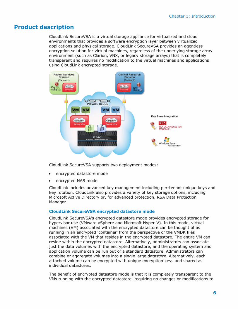
CloudLink SecureVSA is a virtual storage appliance for virtualized and cloud environments that provides a software encryption layer between virtualized
applications and physical storage. CloudLink SecureVSA provides an agentless encryption solution for virtual machines, regardless of the underlying storage array
environment (such as Clarion, VNX, or legacy storage arrays) that is completely
transparent and requires no modification to the virtual machines and applications using CloudLink encrypted storage.
CloudLink SecureVSA supports two deployment modes:
encrypted datastore mode
encrypted NAS mode
CloudLink includes advanced key management including per-tenant unique keys and key rotation. CloudLink also provides a variety of key storage options, including
Microsoft Active Directory or, for advanced protection, RSA Data Protection Manager.
CloudLink SecureVSA encrypted datastore mode
CloudLink SecureVSA’s encrypted datastore mode provides encrypted storage for hypervisor use (VMware vSphere and Microsoft Hyper-V). In this mode, virtual
machines (VM) associated with the encrypted datastore can be thought of as running in an encrypted ‘container’ from the perspective of the VMDK files
associated with the VM that resides in the encrypted datastore. The entire VM can
reside within the encrypted datastore. Alternatively, administrators can associate just the data volumes with the encrypted datastore, and the operating system and
application volume can be run out of a standard datastore. Administrators can combine or aggregate volumes into a single large datastore. Alternatively, each
attached volume can be encrypted with unique encryption keys and shared as individual datastores.
The benefit of encrypted datastore mode is that it is completely transparent to the VMs running with the encrypted datastore, requiring no changes or modifications to
Chapter 1: Introduction
7
virtualized servers and applications (agentless). This mode also offers the benefits of supporting standard VMware features such as DRS, HA, FT, and Storage vMotion.
CloudLink SecureVSA encrypted NAS mode
CloudLink SecureVSA’s encrypted NAS mode provides encrypted storage at the network level for servers and end users. Like encrypted datastore mode, encrypted
NAS mode is an agentless data-at-rest encryption solution, with the encryption being completely transparent to the server and application attaching or mapping to
the network attached storage. Administrators can combine or aggregate volumes into a single large network share. Alternatively, each attached volume can be
encrypted with unique encryption keys and shared individually.
CloudLink SecureVSA integration for key stores
CloudLink SecureVSA supports the ability to use either Microsoft Active Directory or
RSA Data Protection Manager (DPM) as a key store for production deployments. Optionally, a local key store can be used for trials and evaluations.
RSA DPM is an integrated security solution that delivers extremely efficient and comprehensive data protection. RSA DPM is designed to ensure that large numbers
of keys are preserved, across geographic and organizational boundaries, without risks of key loss or compromise. It distributes encryption keys when and where they
are needed, protecting them in transit and ensuring they are provided only to authenticated and authorized entities.
CloudLink SecureVSA features and benefits summary
Agentless encryption model
Transparent to virtualized servers and applications
Central management
Support for on-premise, hybrid, and multi-cloud deployments
Support for partial encryption
Spans heterogeneous storage environments
Support for RSA Data Protection Manager and Active Directory key stores
Highly scalable
Simplified deployment and management
FIPS 140-2 validation
Solution tested
CloudLink SecureVSA was tested and validated in the EMC VSPEX lab using the
same storage and VM configuration defaults that were detailed in the reference
architecture described in the Proven Infrastructure Guide: EMC VSPEX Private Cloud, VMware vSphere 5.5 for up to 1,000 Virtual Machines document. For completeness,
the CloudLink design described in this guide is configured to support and showcase both the encrypted datastore and NAS implementation models. Partners and
customers can choose the appropriate deployment model that best meets their specific requirements.
Chapter 3: Implementation Process Overview
8
Chapter 2 CloudLink Design Planning
CloudLink is designed and implemented as an overlay for the EMC VSPEX private
cloud reference architecture described in the Proven Infrastructure Guide: EMC VSPEX Private Cloud, VMware vSphere 5.5 for up to 1,000 Virtual Machines
document. For solution consistency, the CloudLink design uses the same sizing and
profiling data and tools as the reference architecture.
The EMC VSPEX private cloud reference architecture is available at VSPEX for Private
Cloud Reference Architecture. This Implementation Guide refers to the reference architecture as the “VSPEX for private cloud reference architecture” or “reference
architecture”.
The reference architecture has the following characteristics that are important for
CloudLink designs.
VNX configuration for block versus file (NFS) access
The VNX storage array supports both block and file access to the VMware vSphere
virtual environment. For CloudLink SecureVSA deployments, block access to the VNX storage array provides significantly higher performance than file access and is the
recommended configuration.
Once the VNX storage array has been configured to support block access, the next decision is to determine whether raw device mapping (RDM) or VMFS access should
be configured for CloudLink SecureVSA. The selected storage array access method will determine the CloudLink datastore type.
RDM access supports CloudLink iSCSI datastores
VMFS access supports CloudLink NFS datastores
The decision for which type of storage array access and CloudLink datastore type should be implemented will vary depending upon the customer’s requirements and
operation models.
When performance is the primary consideration, we recommend implementing RDM and CloudLink SecureVSA iSCSI datastores. When ease of administration and
flexibility in terms of the size of datastores to be provisioned are priorities, we recommend VMFS and CloudLink SecureVSA NFS datastores. This Implementation
Guide describes a VMFS and CloudLink SecureVSA NFS datastore configuration.
Note: CloudLink SecureVSA supports both physical and virtual RDM, with virtual
RDM recommended in order to preserve VMware functionality such as snapshots, etc.
Solution hardware
EMC VNX5400 array – provides storage to vSphere hosts for up to 300 virtual
machines
EMC VNX5600 array – provides storage to vSphere hosts for up to 600 virtual
EMC VNX5800 array – provides storage to vSphere hosts for up to 1,000 virtual machines
Version of VMware supported
VMware vSphere 5.1 and 5.5.
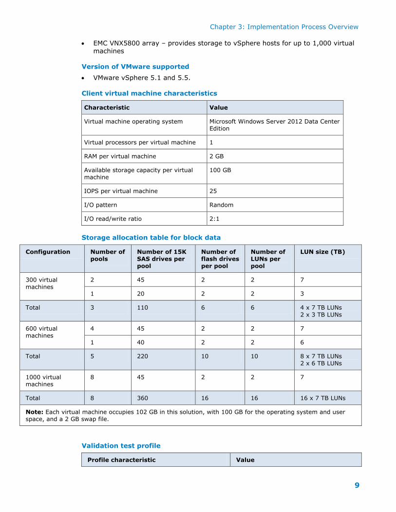
Client virtual machine characteristics
Characteristic Value
Virtual machine operating system Microsoft Windows Server 2012 Data Center Edition
Virtual processors per virtual machine 1
RAM per virtual machine 2 GB
Available storage capacity per virtual machine
100 GB
IOPS per virtual machine 25
I/O pattern Random
I/O read/write ratio 2:1
Storage allocation table for block data
Configuration Number of pools
Number of 15K SAS drives per pool
Number of flash drives per pool
Number of LUNs per pool
LUN size (TB)
300 virtual
machines
2 45 2 2 7
1 20 2 2 3
Total 3 110 6 6 4 x 7 TB LUNs
2 x 3 TB LUNs
600 virtual machines
4 45 2 2 7
1 40 2 2 6
Total 5 220 10 10 8 x 7 TB LUNs
2 x 6 TB LUNs
1000 virtual machines
8 45 2 2 7
Total 8 360 16 16 16 x 7 TB LUNs
Note: Each virtual machine occupies 102 GB in this solution, with 100 GB for the operating system and user space, and a 2 GB swap file.
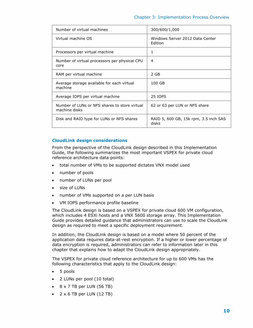
Validation test profile
Profile characteristic Value
Chapter 3: Implementation Process Overview
10
Number of virtual machines 300/600/1,000
Virtual machine OS Windows Server 2012 Data Center
Edition
Processors per virtual machine 1
Number of virtual processors per physical CPU
core
4
RAM per virtual machine 2 GB
Average storage available for each virtual
machine
100 GB
Average IOPS per virtual machine 25 IOPS
Number of LUNs or NFS shares to store virtual
machine disks
62 or 63 per LUN or NFS share
Disk and RAID type for LUNs or NFS shares RAID 5, 600 GB, 15k rpm, 3.5 inch SAS
disks
CloudLink design considerations
From the perspective of the CloudLink design described in this Implementation Guide, the following summarizes the most important VSPEX for private cloud
reference architecture data points:
total number of VMs to be supported dictates VNX model used
number of pools
number of LUNs per pool
size of LUNs
number of VMs supported on a per LUN basis
VM IOPS performance profile baseline
The CloudLink design is based on a VSPEX for private cloud 600 VM configuration, which includes 4 ESXi hosts and a VNX 5600 storage array. This Implementation
Guide provides detailed guidance that administrators can use to scale the CloudLink design as required to meet a specific deployment requirement.
In addition, the CloudLink design is based on a model where 50 percent of the
application data requires data-at-rest encryption. If a higher or lower percentage of
data encryption is required, administrators can refer to information later in this chapter that explains how to adapt the CloudLink design appropriately.
The VSPEX for private cloud reference architecture for up to 600 VMs has the
following characteristics that apply to the CloudLink design:
5 pools
2 LUNs per pool (10 total)
8 x 7 TB per LUN (56 TB)
2 x 6 TB per LUN (12 TB)
Chapter 3: Implementation Process Overview
11
62 VMs per LUN
The VSPEX architecture used for the purpose of this Implementation Guide includes
4 ESXi hosts with 1 ESXi host dedicated to hosting infrastructure components such as AD, DNS, and so on. The three remaining hosts were dedicated to hosting VM
workloads (50 VMs per host).
Each ESXi host is assigned a LUN from which a datastore is created from (7 TB in
size) to support 50 VMs on each host.
This CloudLink design assumes that 50 percent of the workload VMs requires data-at-rest encryption, which translates to 2.5 TB of encrypted storage (25 VMs x
100 GB of allocated disk space). An additional 1 TB of storage is allocated to accommodate Storage vMotion and DRS capacity balancing operations. These
assumptions result in a total of 3.5 TB of encrypted storage per host. This CloudLink
design assumes no data-at-rest encryption requirements for the infrastructure components, and allocates 7 TB of standard datastore storage to the host for the
management infrastructure VMs.
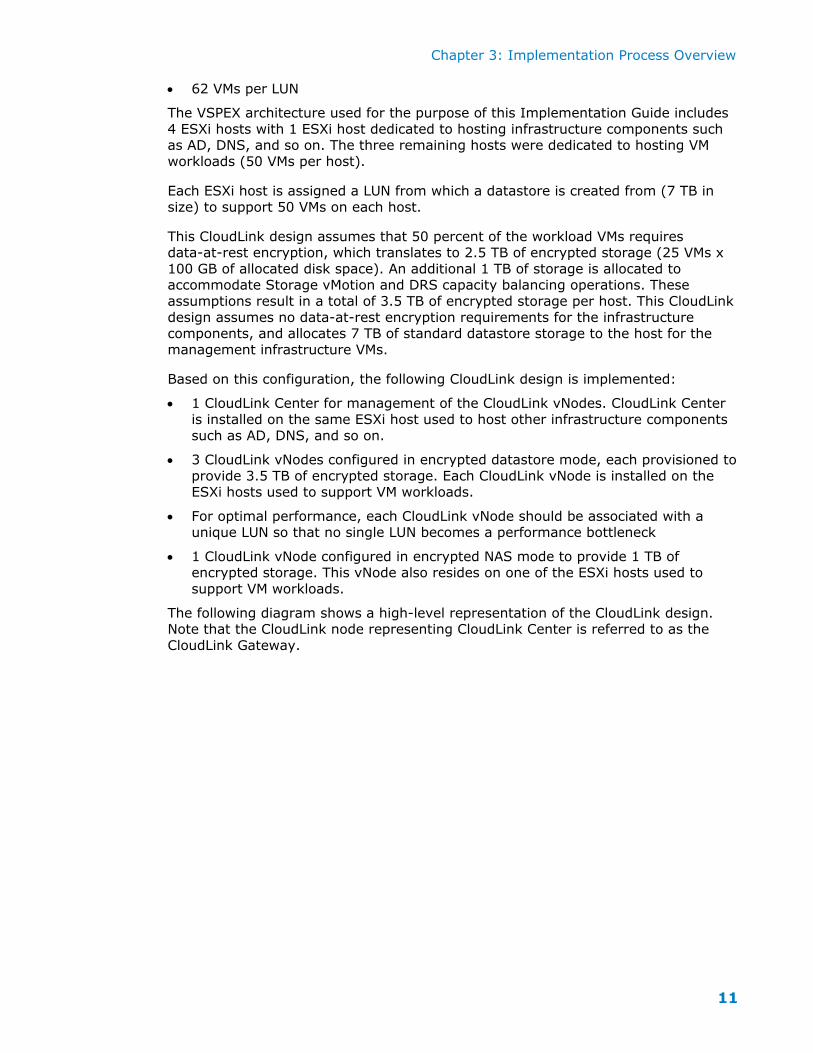
Based on this configuration, the following CloudLink design is implemented:
1 CloudLink Center for management of the CloudLink vNodes. CloudLink Center
is installed on the same ESXi host used to host other infrastructure components
such as AD, DNS, and so on.
3 CloudLink vNodes configured in encrypted datastore mode, each provisioned to
provide 3.5 TB of encrypted storage. Each CloudLink vNode is installed on the ESXi hosts used to support VM workloads.
For optimal performance, each CloudLink vNode should be associated with a unique LUN so that no single LUN becomes a performance bottleneck
1 CloudLink vNode configured in encrypted NAS mode to provide 1 TB of encrypted storage. This vNode also resides on one of the ESXi hosts used to
support VM workloads.
The following diagram shows a high-level representation of the CloudLink design. Note that the CloudLink node representing CloudLink Center is referred to as the
CloudLink Gateway.
Chapter 3: Implementation Process Overview
12
CloudLink performance sizing
CloudLink is licensed to support up to 10 TB of encrypted storage per CloudLink vNode. However, the allocated size of encrypted storage per vNode depends on the
number of VMs allocated per vNode and the individual VMs’ performance requirements from an IOPS and latency perspective. Additional vNodes can be
added to the configuration to support the volume of encrypted data required or for
performance requirements.
Measuring performance is always subjective as many factors can influence the performance seen in labs versus production environments, and even between two
nearly identical environments. As a baseline reference point, a single CloudLink vNode can support the following throughput assuming the network, compute and
storage resources are available to support CloudLink’s resource requirements and
that a typical VNX storage configuration has been implemented (that is, a combination of SSD and SAS drives).
CloudLink supports the ability to scale horizontally by installing vNodes on additional ESXi hosts and on additional LUNS to ensure no utilization bottlenecks at the
compute or storage layers.
Performance will vary, so this baseline information is as guidance only, with the
implemented solution validated using the intended environment. Note that the performance numbers quoted above do not reflect the performance benefits of the
VNX SSD drives as the test data used was larger than the SSD drive to reflect a worst case scenario.
Chapter 3: Implementation Process Overview
13
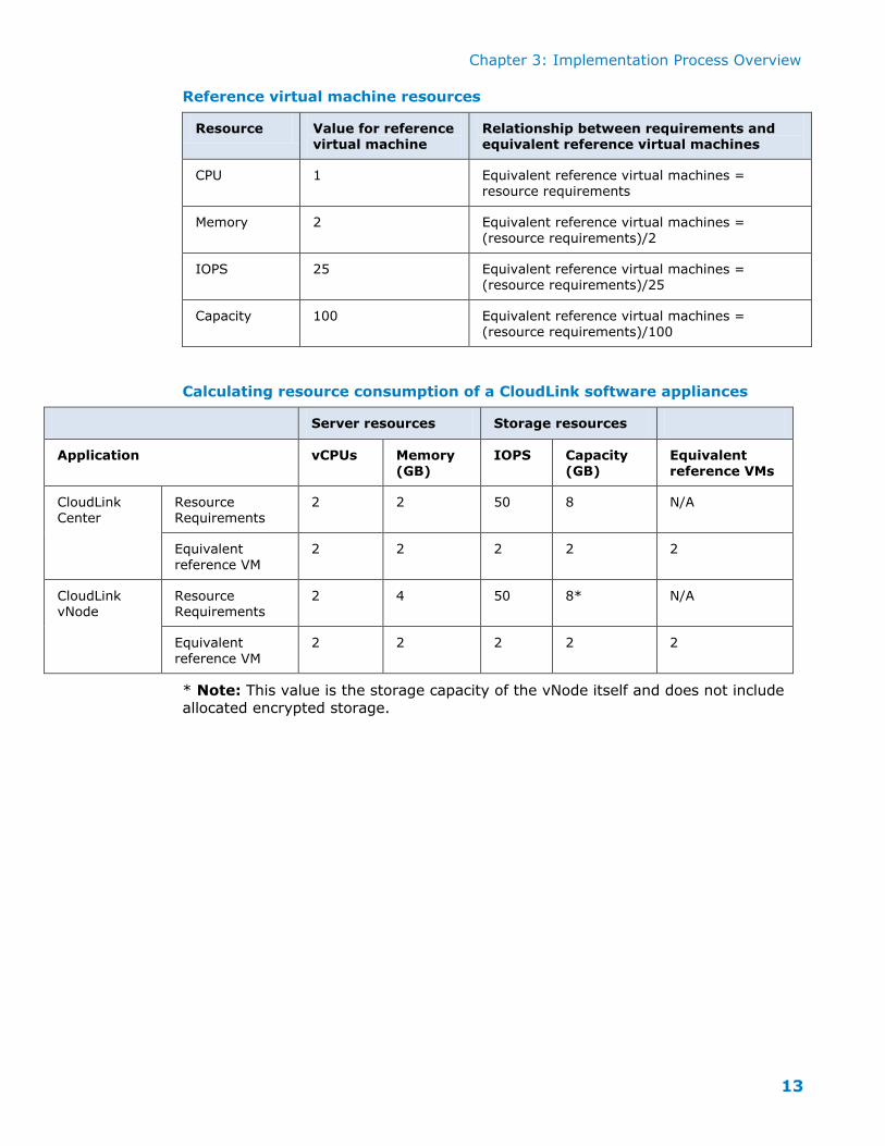
Reference virtual machine resources
Resource Value for reference virtual machine
Relationship between requirements and equivalent reference virtual machines
Calculating resource consumption of a CloudLink software appliances
Server resources Storage resources
Application vCPUs Memory
(GB)
IOPS Capacity
(GB)
Equivalent
reference VMs
CloudLink Center
Resource Requirements
2 2 50 8 N/A
Equivalent
reference VM
2 2 2 2 2
CloudLink vNode
Resource Requirements
2 4 50 8* N/A
Equivalent
reference VM
2 2 2 2 2
* Note: This value is the storage capacity of the vNode itself and does not include
allocated encrypted storage.
Chapter 3: Implementation Process Overview
14
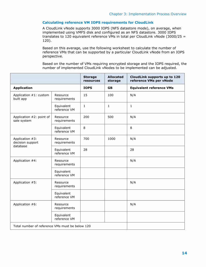
Calculating reference VM IOPS requirements for CloudLink
A CloudLink vNode supports 3000 IOPS (NFS datastore mode), on average, when
implemented using VMFS disk and configured as an NFS datastore. 3000 IOPS
translates to 120 equivalent reference VMs in total per CloudLink vNode (3000/25 = 120).
Based on this average, use the following worksheet to calculate the number of
reference VMs that can be supported by a particular CloudLink vNode from an IOPS perspective.
Based on the number of VMs requiring encrypted storage and the IOPS required, the number of implemented CloudLink vNodes to be implemented can be adjusted.
Storage resources
Allocated storage
CloudLink supports up to 120 reference VMs per vNode
Application IOPS GB Equivalent reference VMs
Application #1: custom built app
Resource requirements
15 100 N/A
Equivalent
reference VM
1 1 1
Application #2: point of
sale system
Resource
requirements
200 500 N/A
Equivalent
reference VM
8 8
Application #3:
decision support
database
Resource
requirements
700 1000 N/A
Equivalent reference VM
28 28
Application #4: Resource
requirements
N/A
Equivalent
reference VM
Application #5: Resource
requirements
N/A
Equivalent
reference VM
Application #6: Resource requirements
N/A
Equivalent
reference VM
Total number of reference VMs must be below 120
Chapter 3: Implementation Process Overview
15
Chapter 3 Implementation Process Overview
This section provides an overview of the implementation process from
pre-deployment preparation to deployment verification.
Pre-deployment
1. Prepare design.
Complete the checklist provided in “Appendix A: Pre-Deployment Checklist”,
which includes information such as the volume of data under management, the applications accessing the data, and the location of the data in the network.
2. Design solution.
Using the VSPEX for private cloud reference architecture, engineer the system
resources based on actual workloads in place of VSPEX reference workloads. For
information about breaks requirements for CPU, memory, storage size and storage IO components, see the following sections in “Chapter 4 Solution
Architecture Overview” of the reference architecture document: “Sizing guidelines”, “Reference workload”, and “Applying the reference workload”. For
convenience, this information has been included this Implementation Guide in “Chapter 1 CloudLink Design Planning”. Follow these same guidelines when
designing the CloudLink SecureVSA configuration.
3. Plan deployment.
Procure solution components.
Determine order of installation of the solutions components.
Verify correct operation of each component using appropriate methods.
Work with members of IT team to plan updates (for example, reachability between network nodes).
4. Confirm pre-requisites prior to deployment.
10G connections between the storage array and all ESXi hosts as per the VSPEX for private cloud reference architecture.
10G ESXi interconnect as per the VSPEX for private cloud reference architecture.
Validate the VSPEX configuration is operating properly before starting the CloudLink deployment. For example, all components are accessible and
communicating without interference from firewalls, and so on.
Chapter 3: Implementation Process Overview
16
Deployment
5. Install and configure.
Start from the physical, computing storage, and networking as per the
VSPEX for private cloud reference architecture. Overlay encrypted storage on the design. Add CloudLink. Add guest VMs (servers and/or clients). For
CloudLink, test a single vNode first before deploying all vNodes.
Refer to the CloudLink SecureVSA VMware VSphere Deployment Guide for specific instructions.
6. Test and verify.
Verify system components (such as hardware) as they are installed. The
CloudLink design assumes that physical hardware is fully verified prior to CloudLink SecureVSA installation.
We recommend using two validation profiles: a small profile for validation of the first encrypted storage function and a full-scale profile for validation of
the entire encrypted storage solution. The full-scale profile can initially be
validated with test applications and revalidated as the actual applications and guests are installed and integrated onto the system.
Perform performance tuning as required (including alignment, caching, SSD, and boot volume).
Chapter 3: Implementation Process Overview
17
Chapter 4 Key Store Configuration
Selecting a key store for the CloudLink deployment
Before starting the CloudLink deployment, determine the encryption key store that will be used: Microsoft Active Directory or RSA Data Protection Manager (DPM).
For deployments with higher security assurance requirements, we recommend using
RSA DPM as the encryption key store.
Configuring Active Directory as a key store
To use Active Directory to store CloudLink encryption keys, deploy a Windows Server so that it will be accessible by CloudLink Center from its private network.
During this procedure, you must provide the host name of the Windows Server. To
use the host name, you must have already set up the DNS server.
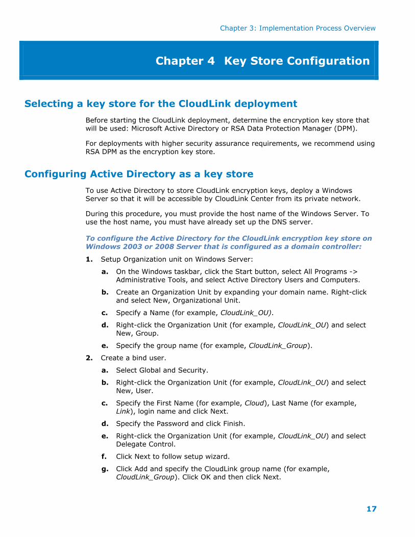
To configure the Active Directory for the CloudLink encryption key store on
Windows 2003 or 2008 Server that is configured as a domain controller:
1. Setup Organization unit on Windows Server:
a. On the Windows taskbar, click the Start button, select All Programs -> Administrative Tools, and select Active Directory Users and Computers.
b. Create an Organization Unit by expanding your domain name. Right-click and select New, Organizational Unit.
c. Specify a Name (for example, CloudLink_OU).
d. Right-click the Organization Unit (for example, CloudLink_OU) and select
New, Group.
e. Specify the group name (for example, CloudLink_Group).
2. Create a bind user.
a. Select Global and Security.
b. Right-click the Organization Unit (for example, CloudLink_OU) and select
New, User.
c. Specify the First Name (for example, Cloud), Last Name (for example,
Link), login name and click Next.
d. Specify the Password and click Finish.
e. Right-click the Organization Unit (for example, CloudLink_OU) and select Delegate Control.
f. Click Next to follow setup wizard.
g. Click Add and specify the CloudLink group name (for example, CloudLink_Group). Click OK and then click Next.
Chapter 3: Implementation Process Overview
18
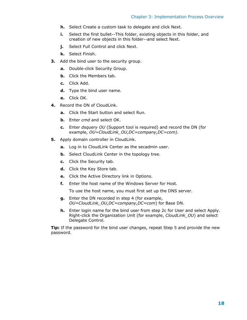
h. Select Create a custom task to delegate and click Next.
i. Select the first bullet--This folder, existing objects in this folder, and
creation of new objects in this folder--and select Next.
j. Select Full Control and click Next.
k. Select Finish.
3. Add the bind user to the security group.
a. Double-click Security Group.
b. Click the Members tab.
c. Click Add.
d. Type the bind user name.
e. Click OK.
4. Record the DN of CloudLink.
a. Click the Start button and select Run.
b. Enter cmd and select OK.
c. Enter dsquery OU (Support tool is required) and record the DN (for
example, OU=CloudLink_OU,DC=company,DC=com).
5. Apply domain controller in CloudLink.
a. Log in to CloudLink Center as the secadmin user.
b. Select CloudLink Center in the topology tree.
c. Click the Security tab.
d. Click the Key Store tab.
e. Click the Active Directory link in Options.
f. Enter the host name of the Windows Server for Host.
To use the host name, you must first set up the DNS server.
g. Enter the DN recorded in step 4 (for example, OU=CloudLink_OU,DC=company,DC=com) for Base DN.
h. Enter login name for the bind user from step 2c for User and select Apply.
Right-click the Organization Unit (for example, CloudLink_OU) and select Delegate Control.
Tip: If the password for the bind user changes, repeat Step 5 and provide the new password.
Chapter 3: Implementation Process Overview
19
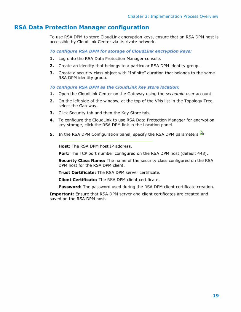
RSA Data Protection Manager configuration
To use RSA DPM to store CloudLink encryption keys, ensure that an RSA DPM host is accessible by CloudLink Center via its rivate network.
To configure RSA DPM for storage of CloudLink encryption keys:
1. Log onto the RSA Data Protection Manager console.
2. Create an identity that belongs to a particular RSA DPM identity group.
3. Create a security class object with “Infinite” duration that belongs to the same RSA DPM identity group.
To configure RSA DPM as the CloudLink key store location:
1. Open the CloudLink Center on the Gateway using the secadmin user account.
2. On the left side of the window, at the top of the VMs list in the Topology Tree,
select the Gateway.
3. Click Security tab and then the Key Store tab.
4. To configure the CloudLink to use RSA Data Protection Manager for encryption key storage, click the RSA DPM link in the Location panel.
5. In the RSA DPM Configuration panel, specify the RSA DPM parameters
Host: The RSA DPM host IP address.
Port: The TCP port number configured on the RSA DPM host (default 443).
Security Class Name: The name of the security class configured on the RSA
DPM host for the RSA DPM client.
Trust Certificate: The RSA DPM server certificate.
Client Certificate: The RSA DPM client certificate.
Password: The password used during the RSA DPM client certificate creation.
Important: Ensure that RSA DPM server and client certificates are created and
saved on the RSA DPM host.
Chapter 5: Testing and Verification
20
Chapter 5 Installation and Configuration
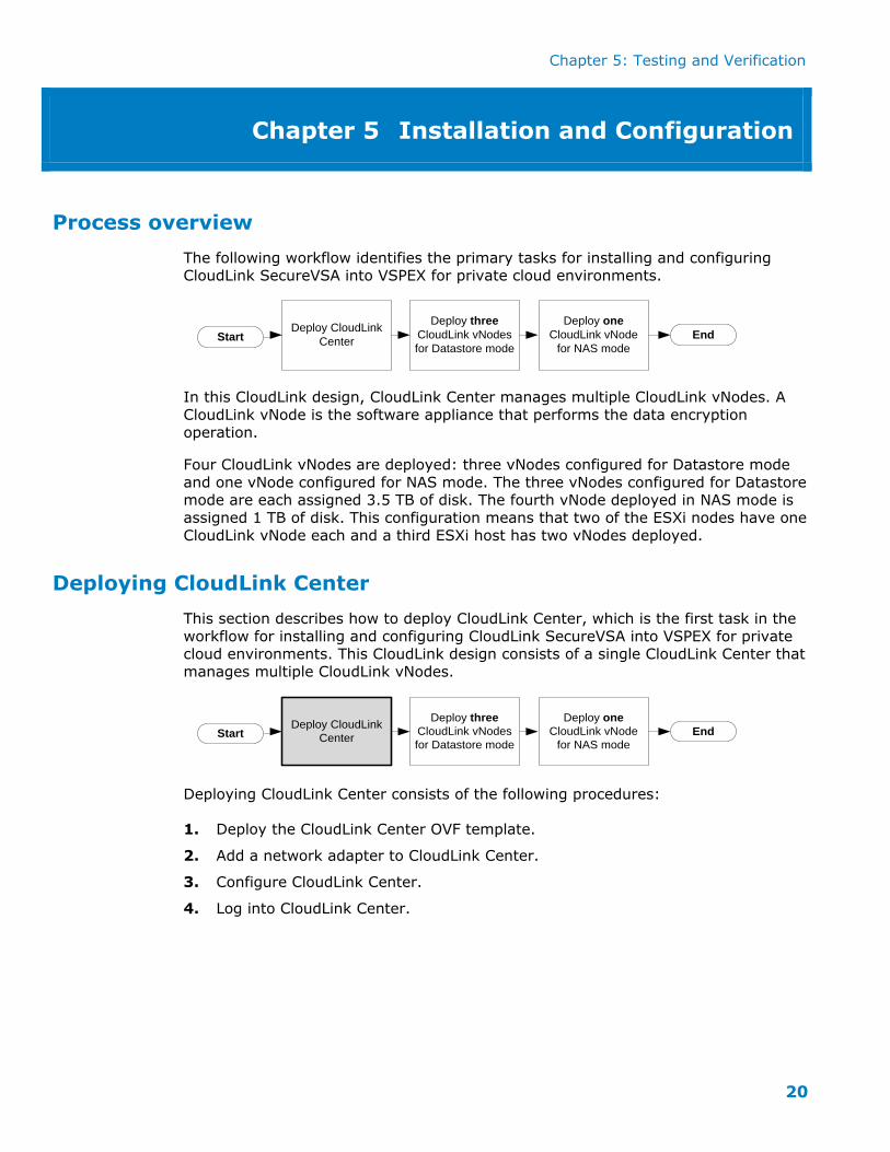
Process overview
The following workflow identifies the primary tasks for installing and configuring CloudLink SecureVSA into VSPEX for private cloud environments.
Start End
Deploy three
CloudLink vNodes
for Datastore mode
Deploy CloudLink
Center
Deploy one
CloudLink vNode
for NAS mode
In this CloudLink design, CloudLink Center manages multiple CloudLink vNodes. A
CloudLink vNode is the software appliance that performs the data encryption operation.
Four CloudLink vNodes are deployed: three vNodes configured for Datastore mode
and one vNode configured for NAS mode. The three vNodes configured for Datastore mode are each assigned 3.5 TB of disk. The fourth vNode deployed in NAS mode is
assigned 1 TB of disk. This configuration means that two of the ESXi nodes have one
CloudLink vNode each and a third ESXi host has two vNodes deployed.
Deploying CloudLink Center
This section describes how to deploy CloudLink Center, which is the first task in the
workflow for installing and configuring CloudLink SecureVSA into VSPEX for private cloud environments. This CloudLink design consists of a single CloudLink Center that
manages multiple CloudLink vNodes.
Start End
Deploy three
CloudLink vNodes
for Datastore mode
Deploy CloudLink
Center
Deploy one
CloudLink vNode
for NAS mode
Deploying CloudLink Center consists of the following procedures:
1. Deploy the CloudLink Center OVF template.
2. Add a network adapter to CloudLink Center.
3. Configure CloudLink Center.
4. Log into CloudLink Center.
Chapter 5: Testing and Verification
21
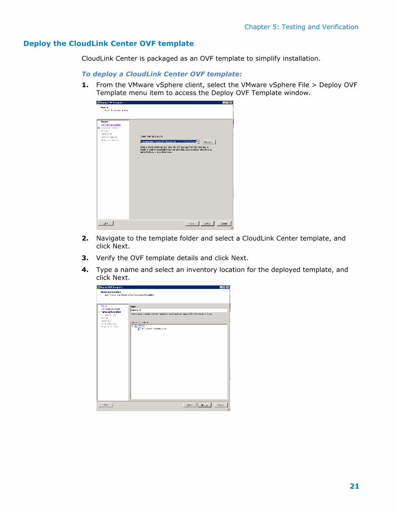
Deploy the CloudLink Center OVF template
CloudLink Center is packaged as an OVF template to simplify installation.
To deploy a CloudLink Center OVF template:
1. From the VMware vSphere client, select the VMware vSphere File > Deploy OVF
Template menu item to access the Deploy OVF Template window.
2. Navigate to the template folder and select a CloudLink Center template, and
click Next.
3. Verify the OVF template details and click Next.
4. Type a name and select an inventory location for the deployed template, and
click Next.
Chapter 5: Testing and Verification
22
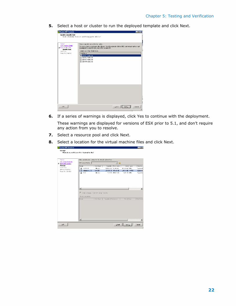
5. Select a host or cluster to run the deployed template and click Next.
6. If a series of warnings is displayed, click Yes to continue with the deployment.
These warnings are displayed for versions of ESX prior to 5.1, and don’t require
any action from you to resolve.
7. Select a resource pool and click Next.
8. Select a location for the virtual machine files and click Next.
Chapter 5: Testing and Verification
23
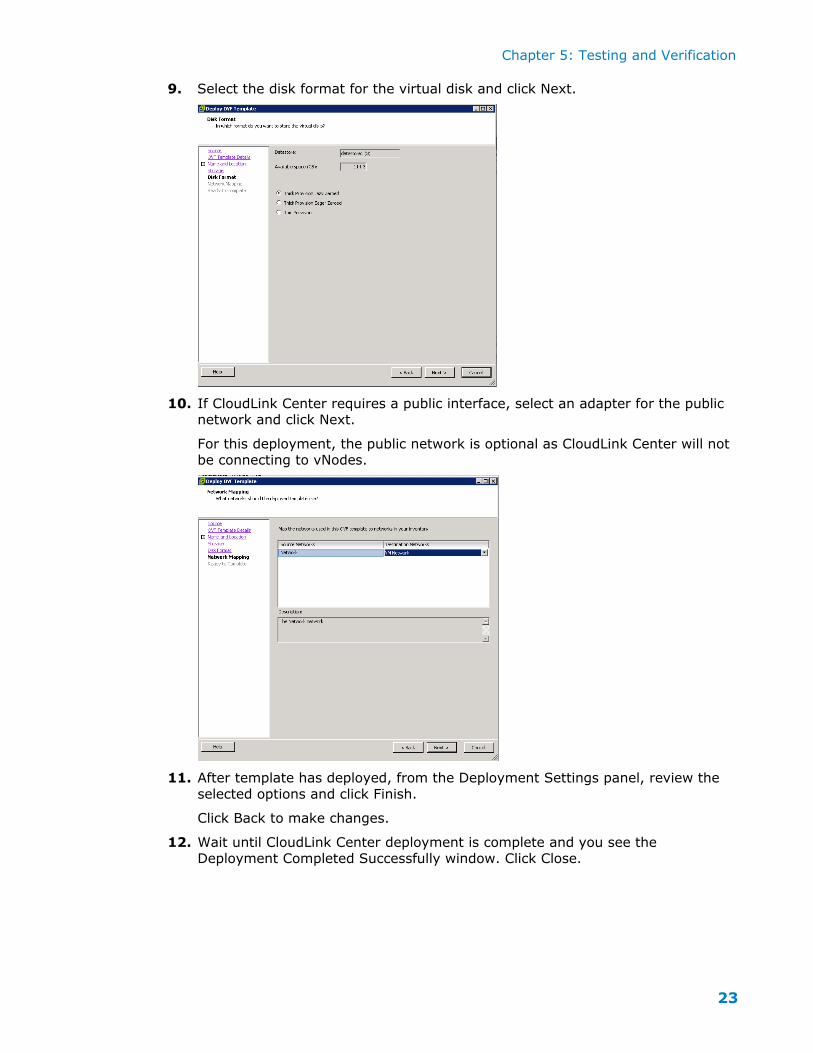
9. Select the disk format for the virtual disk and click Next.
10. If CloudLink Center requires a public interface, select an adapter for the public network and click Next.
For this deployment, the public network is optional as CloudLink Center will not be connecting to vNodes.
11. After template has deployed, from the Deployment Settings panel, review the
selected options and click Finish.
Click Back to make changes.
12. Wait until CloudLink Center deployment is complete and you see the Deployment Completed Successfully window. Click Close.
Chapter 5: Testing and Verification
24
Adding a network adapter to CloudLink Center
After deploying an OVF template for CloudLink Center, one network adapter is
assigned to it, which is used for the public interface. The reference to a “public interface” does not mean that it will be used for Internet connectivity, but instead,
refers to a network adapter that will be use for communication with CloudLink vNodes and by browser-based administration.
You need to add a second network adapter configured as a private interface. This interface is not used in the planned configuration, but it does need to be defined.
In summary, you define two network interfaces in the following order:
a public interface defined in the OVF template
a private interface that you add after deploying the OVF template
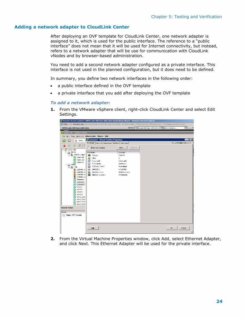
To add a network adapter:
1. From the VMware vSphere client, right-click CloudLink Center and select Edit Settings.
2. From the Virtual Machine Properties window, click Add, select Ethernet Adapter, and click Next. This Ethernet Adapter will be used for the private interface.
Chapter 5: Testing and Verification
25
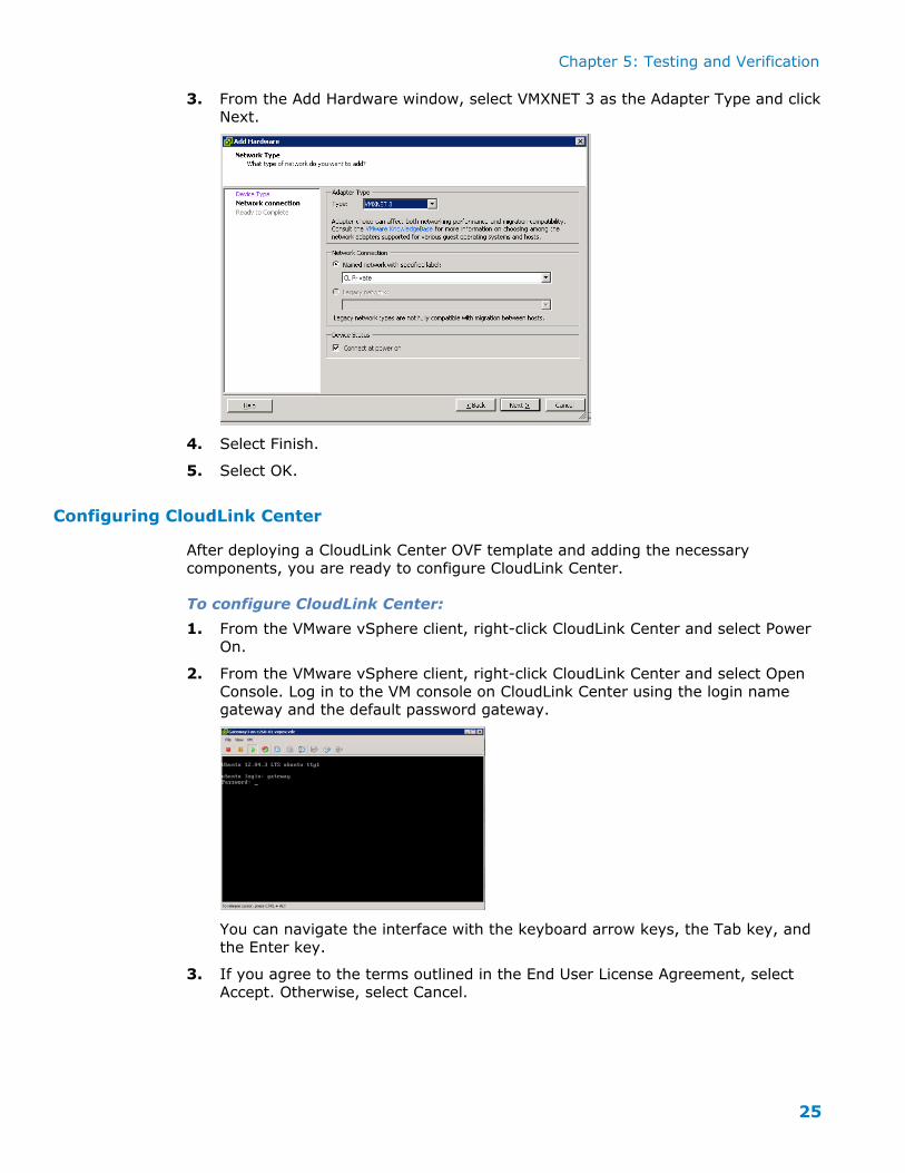
3. From the Add Hardware window, select VMXNET 3 as the Adapter Type and click Next.
4. Select Finish.
5. Select OK.
Configuring CloudLink Center
After deploying a CloudLink Center OVF template and adding the necessary
components, you are ready to configure CloudLink Center.
To configure CloudLink Center:
1. From the VMware vSphere client, right-click CloudLink Center and select Power
On.
2. From the VMware vSphere client, right-click CloudLink Center and select Open
Console. Log in to the VM console on CloudLink Center using the login name gateway and the default password gateway.
You can navigate the interface with the keyboard arrow keys, the Tab key, and
the Enter key.
3. If you agree to the terms outlined in the End User License Agreement, select
Accept. Otherwise, select Cancel.
Chapter 5: Testing and Verification
26
4. When prompted, type a new password for the CloudLink Center console and click OK.
You are required to change the default password. Subsequent logins to the console prompt for the new password.
You can change the password after configuring CloudLink Center for the first time. Every time you login to the CloudLink Center console, the Update menu is
displayed. Use the Password command on the Update menu to change the password.
5. Click Confirm after reviewing the configuration information.
The configuration information to be verified depends on the choices you made when you deployed the CloudLink Center OVF template.
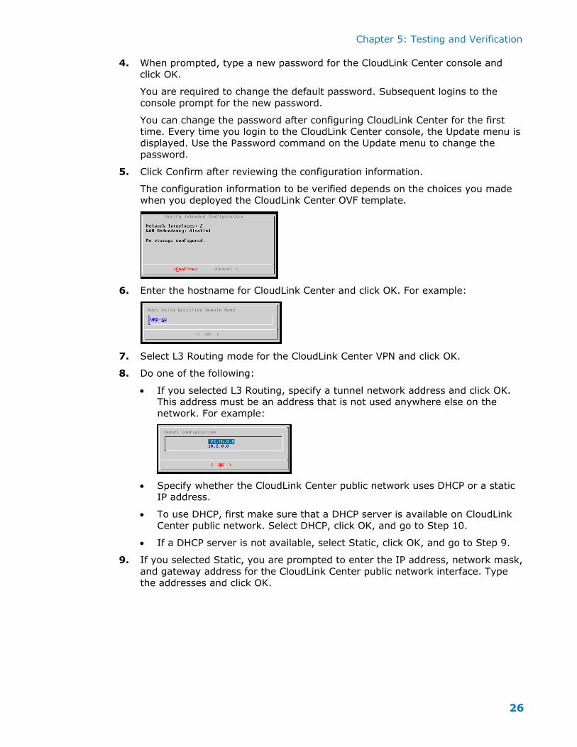
6. Enter the hostname for CloudLink Center and click OK. For example:
7. Select L3 Routing mode for the CloudLink Center VPN and click OK.
8. Do one of the following:
If you selected L3 Routing, specify a tunnel network address and click OK. This address must be an address that is not used anywhere else on the
network. For example:
Specify whether the CloudLink Center public network uses DHCP or a static IP address.
To use DHCP, first make sure that a DHCP server is available on CloudLink Center public network. Select DHCP, click OK, and go to Step 10.
If a DHCP server is not available, select Static, click OK, and go to Step 9.
9. If you selected Static, you are prompted to enter the IP address, network mask,
and gateway address for the CloudLink Center public network interface. Type
the addresses and click OK.
Chapter 5: Testing and Verification
27
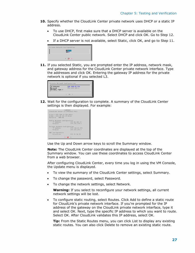
10. Specify whether the CloudLink Center private network uses DHCP or a static IP address.
To use DHCP, first make sure that a DHCP server is available on the CloudLink Center public network. Select DHCP and click OK. Go to Step 12.
If a DHCP server is not available, select Static, click OK, and go to Step 11.
11. If you selected Static, you are prompted enter the IP address, network mask, and gateway address for the CloudLink Center private network interface. Type
the addresses and click OK. Entering the gateway IP address for the private network is optional if you selected L3.
12. Wait for the configuration to complete. A summary of the CloudLink Center settings is then displayed. For example:
Use the Up and Down arrow keys to scroll the Summary window.
Note: The CloudLink Center coordinates are displayed at the top of the Summary window. You can use these coordinates to access CloudLink Center
from a web browser.
After configuring CloudLink Center, every time you log in using the VM Console,
the Update menu is displayed.
To view the summary of the CloudLink Center settings, select Summary.
To change the password, select Password.
To change the network settings, select Network.
Warning: If you select to reconfigure your network settings, all current
network settings will be lost.
To configure static routing, select Routes. Click Add to define a static route
for CloudLink’s private network interface. If you’re prompted for the IP address of the gateway on the CloudLink private network interface, type it
and select OK. Next, type the specific IP address to which you want to route. Select OK. After CloudLink validates this IP address, select OK.
Tip: From the Static Routes menu, you can click List to display any existing static routes. You can also click Delete to remove an existing static route.
Chapter 5: Testing and Verification
28
The Diagnostics option is intended for use under the direction of AFORE Support.
Log in to CloudLink Center
With CloudLink Center deployed and its network interfaces configured, you can now
use a web browser to connect to it and log in.
To connect to and log in to CloudLink Center:
In the web browser address bar, type the following:
https:// IpAddress:8443
where IpAddress represents the coordinates displayed at the top of the
Summary.
Chapter 5: Testing and Verification
29
Deploying vNodes for Datastore mode
This section describes how to deploy CloudLink vNodes configured for Datastore mode, which is the second task in the workflow for installing and configuring
CloudLink SecureVSA into VSPEX for private cloud environments. You will deploy three CloudLink vNodes for this mode.
Start End
Deploy three
CloudLink vNodes
for Datastore mode
Deploy CloudLink
Center
Deploy one
CloudLink vNode
for NAS mode
Deploying a CloudLink vNode for Datastore mode involves the following procedures:
1. Deploy the OVF template for a vNode.
The base template deployment includes one network adapter for the public
network.
2. Add network adapters and storage devices to the vNode.
3. Configure the vNode.
4. Configure the CloudLink storage.
5. Configure secure ESX datastores.
Note: Optionally, you can merge volumes later, after deploying the vNode. For more information, see the CloudLink SecureVSA VMware VSphere Administration
Guide.
Deploy the OVF template for the vNode
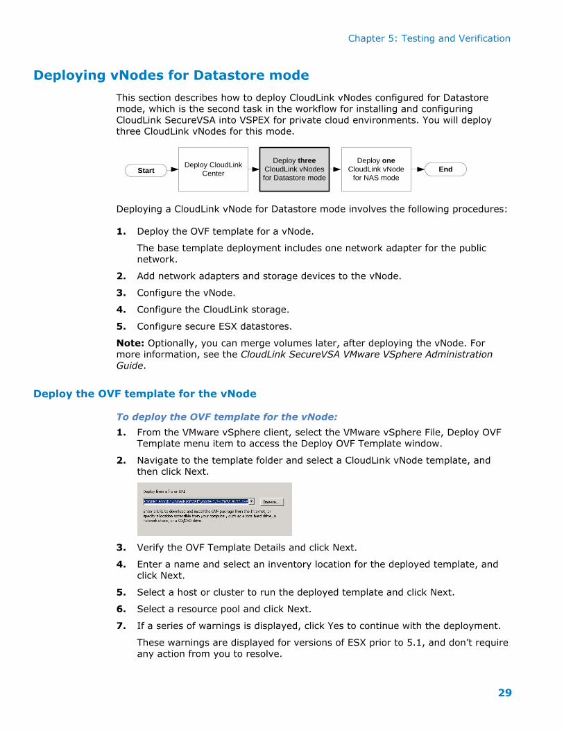
To deploy the OVF template for the vNode:
1. From the VMware vSphere client, select the VMware vSphere File, Deploy OVF Template menu item to access the Deploy OVF Template window.
2. Navigate to the template folder and select a CloudLink vNode template, and then click Next.
3. Verify the OVF Template Details and click Next.
4. Enter a name and select an inventory location for the deployed template, and click Next.
5. Select a host or cluster to run the deployed template and click Next.
6. Select a resource pool and click Next.
7. If a series of warnings is displayed, click Yes to continue with the deployment.
These warnings are displayed for versions of ESX prior to 5.1, and don’t require
any action from you to resolve.
Chapter 5: Testing and Verification
30
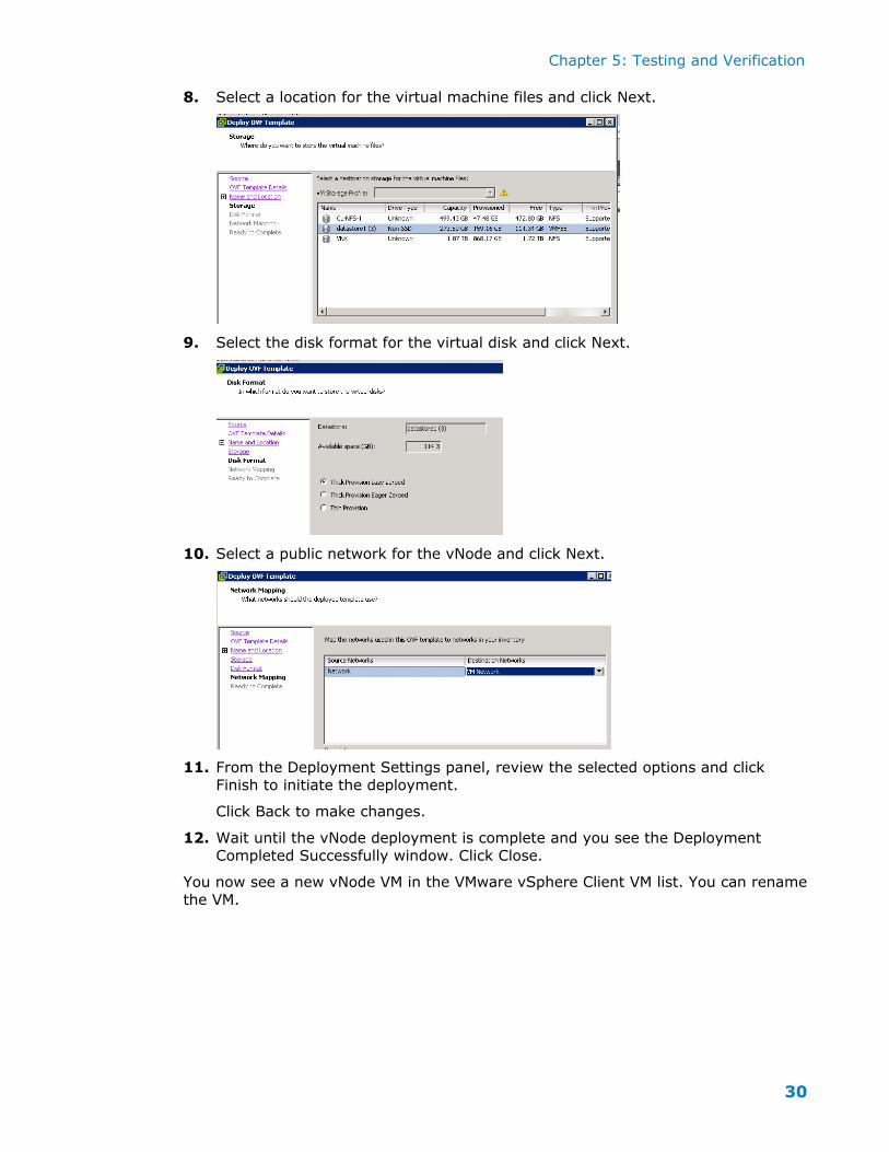
8. Select a location for the virtual machine files and click Next.
9. Select the disk format for the virtual disk and click Next.
10. Select a public network for the vNode and click Next.
11. From the Deployment Settings panel, review the selected options and click
Finish to initiate the deployment.
Click Back to make changes.
12. Wait until the vNode deployment is complete and you see the Deployment
Completed Successfully window. Click Close.
You now see a new vNode VM in the VMware vSphere Client VM list. You can rename
the VM.
Chapter 5: Testing and Verification
31
Adding network adapters and storage devices to the vNode
A network adapter forms part of the vNode OVF template. The included network
adapter is for the CloudLink vNode public network interface. For this deployment configuration, you need to add two additional network adapters, in this specific
order:
The first network adapter that you add is for the SAN interface.
The second network adapter that you add is for the private network interface.
After adding the network adapters to the CloudLink vNode, you add one or more
storage devices.
To add a network adapter for the SAN:
1. From the VMware vSphere client, right-click a vNode and select Edit Settings.
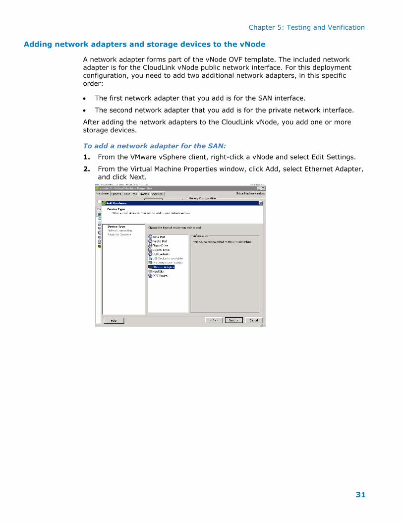
2. From the Virtual Machine Properties window, click Add, select Ethernet Adapter,
and click Next.
Chapter 5: Testing and Verification
32
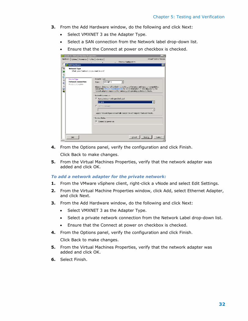
3. From the Add Hardware window, do the following and click Next:
Select VMXNET 3 as the Adapter Type.
Select a SAN connection from the Network label drop-down list.
Ensure that the Connect at power on checkbox is checked.
4. From the Options panel, verify the configuration and click Finish.
Click Back to make changes.
5. From the Virtual Machines Properties, verify that the network adapter was
added and click OK.
To add a network adapter for the private network:
1. From the VMware vSphere client, right-click a vNode and select Edit Settings.
2. From the Virtual Machine Properties window, click Add, select Ethernet Adapter,
and click Next.
3. From the Add Hardware window, do the following and click Next:
Select VMXNET 3 as the Adapter Type.
Select a private network connection from the Network Label drop-down list.
Ensure that the Connect at power on checkbox is checked.
4. From the Options panel, verify the configuration and click Finish.
Click Back to make changes.
5. From the Virtual Machines Properties, verify that the network adapter was added and click OK.
6. Select Finish.
Chapter 5: Testing and Verification
33
Add one or more disks to be encrypted
When the CloudLink vNode is configured in secure datastore mode, all encrypted
volumes it provides are unavailable during format operations. We recommended
that you format all volumes before using any of them for secure ESX datastores.
When multiple virtual disks are assigned to a CloudLink vNode, there are two options for storage configuration:
Each disk can be presented as a separate encrypted volume.
The disks can be merged and presented as a single encrypted volume.
You cannot use the storage until you apply the storage license, as described later in this section.
If you want a volume that is larger than the maximum disk size, you must create
multiple volumes and merge them later. For more information about merging
volumes, see the CloudLink SecureVSA VMware VSphere Administration Guide.
In this CloudLink design, two disks are added to each vNode--a 2TB disk and a 1.5 TB disk--enabling 3.5 TB of encrypted storage for the three vNodes configured in
datastore mode.
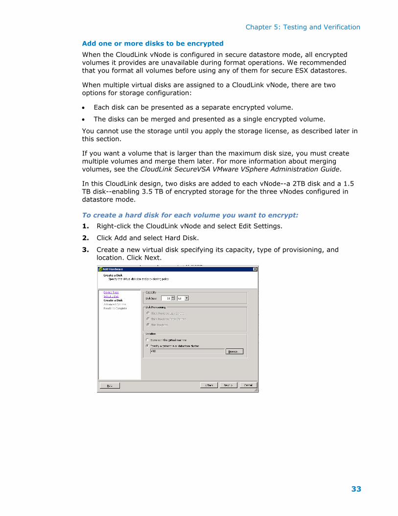
To create a hard disk for each volume you want to encrypt:
1. Right-click the CloudLink vNode and select Edit Settings.
2. Click Add and select Hard Disk.
3. Create a new virtual disk specifying its capacity, type of provisioning, and
location. Click Next.
Chapter 5: Testing and Verification
34
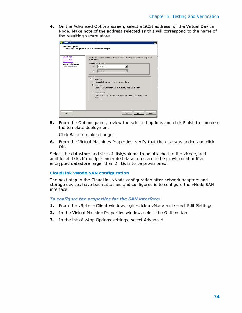
4. On the Advanced Options screen, select a SCSI address for the Virtual Device Node. Make note of the address selected as this will correspond to the name of
the resulting secure store.
5. From the Options panel, review the selected options and click Finish to complete
the template deployment.
Click Back to make changes.
6. From the Virtual Machines Properties, verify that the disk was added and click
OK.
Select the datastore and size of disk/volume to be attached to the vNode, add
additional disks if multiple encrypted datastores are to be provisioned or if an encrypted datastore larger than 2 TBs is to be provisioned.
CloudLink vNode SAN configuration
The next step in the CloudLink vNode configuration after network adapters and storage devices have been attached and configured is to configure the vNode SAN
interface.
To configure the properties for the SAN interface:
1. From the vSphere Client window, right-click a vNode and select Edit Settings.
2. In the Virtual Machine Properties window, select the Options tab.
3. In the list of vApp Options settings, select Advanced.
Chapter 5: Testing and Verification
35
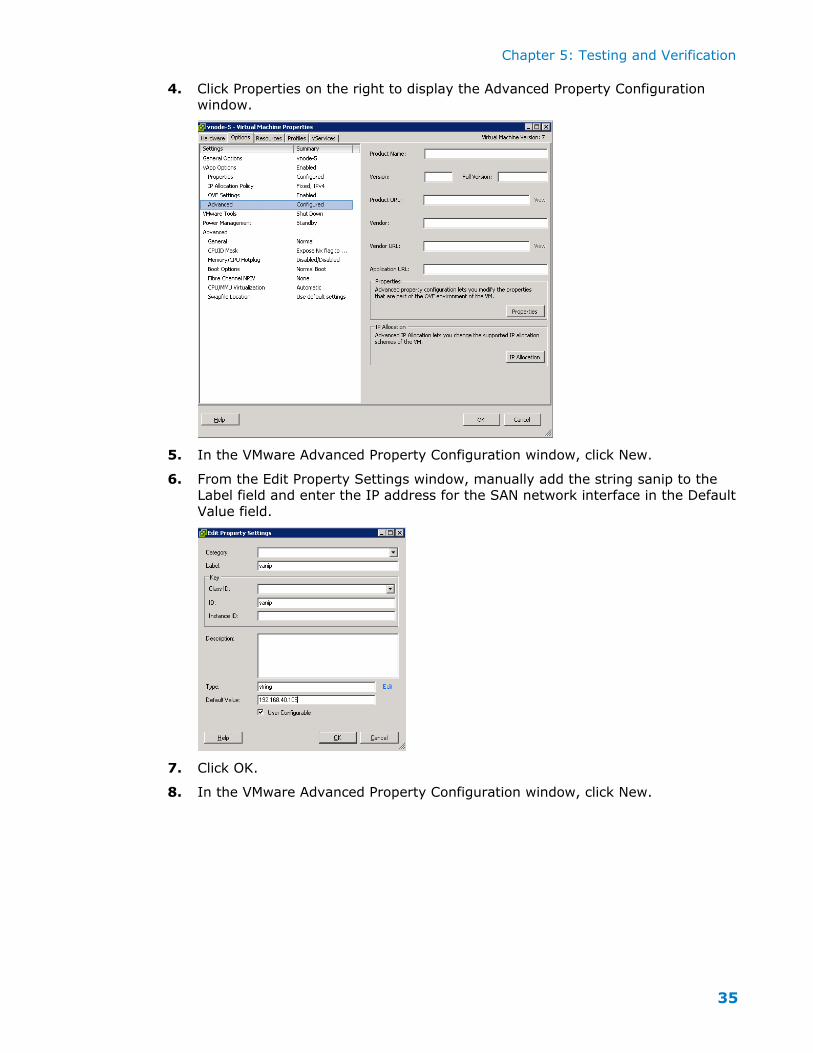
4. Click Properties on the right to display the Advanced Property Configuration window.
5. In the VMware Advanced Property Configuration window, click New.
6. From the Edit Property Settings window, manually add the string sanip to the Label field and enter the IP address for the SAN network interface in the Default
Value field.
7. Click OK.
8. In the VMware Advanced Property Configuration window, click New.
Chapter 5: Testing and Verification
36
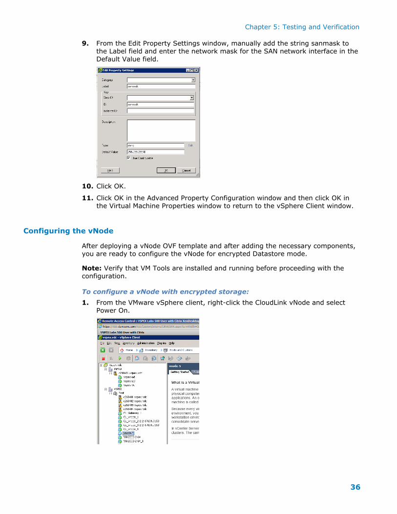
9. From the Edit Property Settings window, manually add the string sanmask to the Label field and enter the network mask for the SAN network interface in the
Default Value field.
10. Click OK.
11. Click OK in the Advanced Property Configuration window and then click OK in the Virtual Machine Properties window to return to the vSphere Client window.
Configuring the vNode
After deploying a vNode OVF template and after adding the necessary components, you are ready to configure the vNode for encrypted Datastore mode.
Note: Verify that VM Tools are installed and running before proceeding with the configuration.
To configure a vNode with encrypted storage:
1. From the VMware vSphere client, right-click the CloudLink vNode and select
Power On.
Chapter 5: Testing and Verification
37
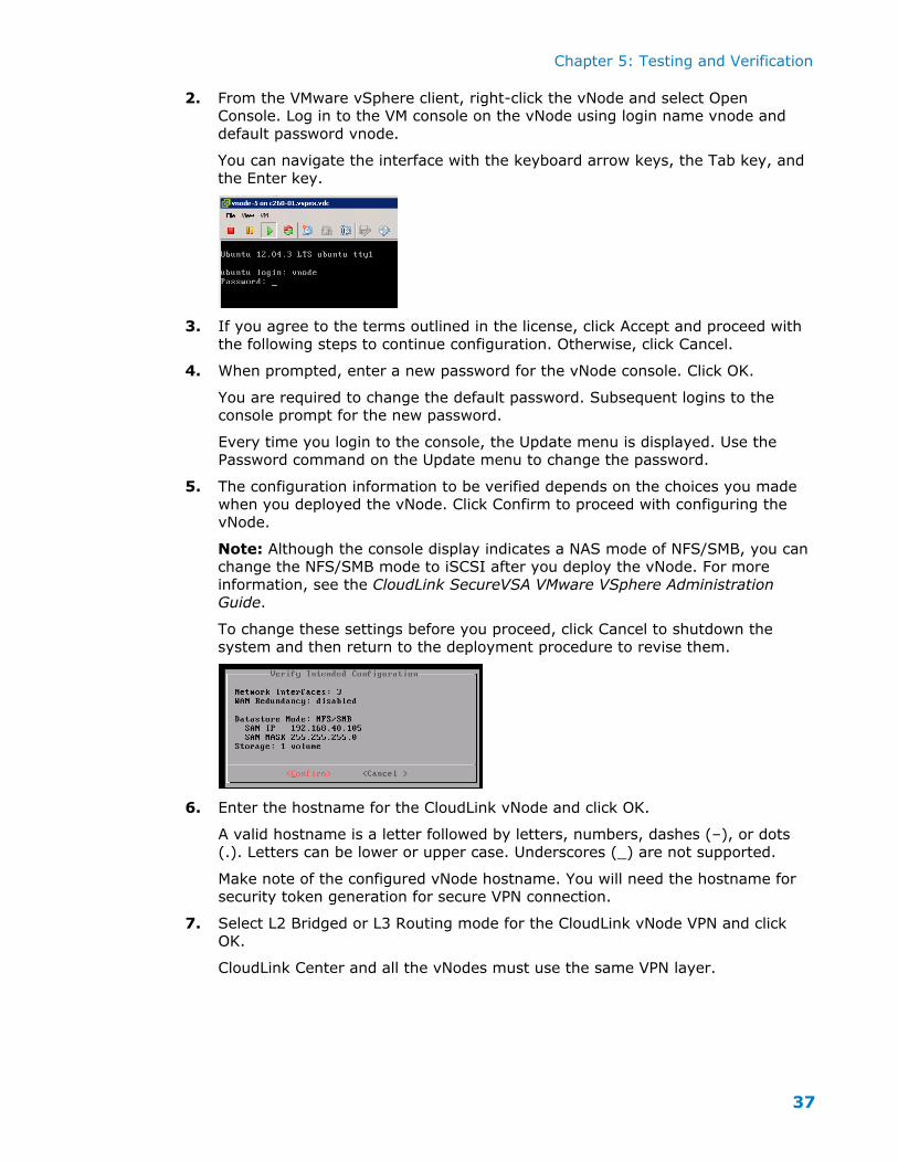
2. From the VMware vSphere client, right-click the vNode and select Open Console. Log in to the VM console on the vNode using login name vnode and
default password vnode.
You can navigate the interface with the keyboard arrow keys, the Tab key, and
the Enter key.
3. If you agree to the terms outlined in the license, click Accept and proceed with
the following steps to continue configuration. Otherwise, click Cancel.
4. When prompted, enter a new password for the vNode console. Click OK.
You are required to change the default password. Subsequent logins to the console prompt for the new password.
Every time you login to the console, the Update menu is displayed. Use the Password command on the Update menu to change the password.
5. The configuration information to be verified depends on the choices you made when you deployed the vNode. Click Confirm to proceed with configuring the
vNode.
Note: Although the console display indicates a NAS mode of NFS/SMB, you can change the NFS/SMB mode to iSCSI after you deploy the vNode. For more
information, see the CloudLink SecureVSA VMware VSphere Administration Guide.
To change these settings before you proceed, click Cancel to shutdown the system and then return to the deployment procedure to revise them.
6. Enter the hostname for the CloudLink vNode and click OK.
A valid hostname is a letter followed by letters, numbers, dashes (–), or dots
(.). Letters can be lower or upper case. Underscores (_) are not supported.
Make note of the configured vNode hostname. You will need the hostname for security token generation for secure VPN connection.
7. Select L2 Bridged or L3 Routing mode for the CloudLink vNode VPN and click OK.
CloudLink Center and all the vNodes must use the same VPN layer.
Chapter 5: Testing and Verification
38
8. Specify whether the vNode public network uses DHCP or a static IP address.
To use DHCP, first make sure that a DHCP server is available on the vNode
public network. Select
DHCP, click OK, and proceed to step 10.
If a DHCP server is not available, select Static, click OK, and proceed to step 9.
9. If you selected Static, you are prompted to enter the IP address and network mask for the vNode public network interface. Type the addresses and click OK.
10. You are prompted to configure the vNode private network. Specify the IP
address, network mask, and gateway address for the vNode private network interface.
To use DHCP, first make sure that a DHCP server is available on the vNode public network. Select DHCP, click OK, and proceed to step 12.
If a DHCP server is not available, select Static, click OK, and proceed to step 11.
11. If you selected Static, you are prompted to enter the IP address, network mask,
and gateway address for the vNode private network interface. Type the addresses and click OK.
In L3 VPN mode with multiple vNodes and one CloudLink Gateway, each
vNode’s private network interface must be configured in a different network.
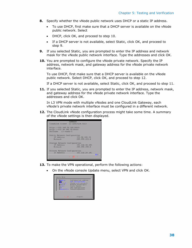
12. The CloudLink vNode configuration process might take some time. A summary
of the vNode settings is then displayed.
13. To make the VPN operational, perform the following actions:
On the vNode console Update menu, select VPN and click OK.
Chapter 5: Testing and Verification
39
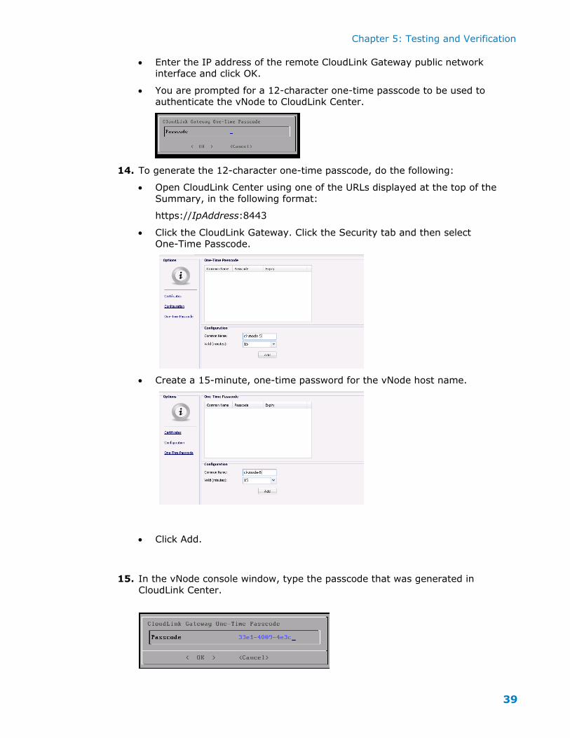
Enter the IP address of the remote CloudLink Gateway public network interface and click OK.
You are prompted for a 12-character one-time passcode to be used to authenticate the vNode to CloudLink Center.
14. To generate the 12-character one-time passcode, do the following:
Open CloudLink Center using one of the URLs displayed at the top of the
Summary, in the following format:
https://IpAddress:8443
Click the CloudLink Gateway. Click the Security tab and then select
One-Time Passcode.
Create a 15-minute, one-time password for the vNode host name.
Click Add.
15. In the vNode console window, type the passcode that was generated in
CloudLink Center.
Chapter 5: Testing and Verification
40
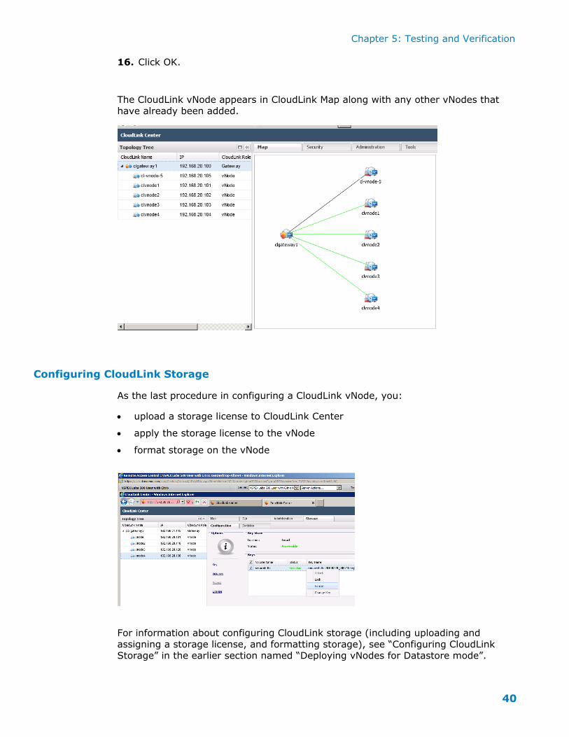
16. Click OK.
The CloudLink vNode appears in CloudLink Map along with any other vNodes that
have already been added.
Configuring CloudLink Storage
As the last procedure in configuring a CloudLink vNode, you:
upload a storage license to CloudLink Center
apply the storage license to the vNode
format storage on the vNode
For information about configuring CloudLink storage (including uploading and
assigning a storage license, and formatting storage), see “Configuring CloudLink Storage” in the earlier section named “Deploying vNodes for Datastore mode”.
Chapter 5: Testing and Verification
41
After configuring storage, the CloudLink encrypted storage is ready to be presented as an encrypted datastore.
Configuring secure ESX datastores
This section describes how to configure secure ESX datastores from the CloudLink
encrypted storage (vNodes using Datastore mode).
Once a CloudLink datastore has been created, any VMDK associated with this
datastore will be encrypted with AES-256 bit encryption. The CloudLink datastore can the thought of as a ‘secure encrypted container’. Any VM or disk/volume
associated with the CloudLink datastore is encrypted transparent to the VM (operating system and applications) and the ESXi hypervisor itself. From an ESXi
hypervisor perspective, all functions such as Storage vMotion and DRS continue to work.
CloudLink encrypted storage supports secure datastores defined as either an NFS or iSCSI storage type.
NFS storage type
To configure secure ESX datastores of the NFS storage type for CloudLink:
1. In the VMware vSphere window, select the ESX host running CloudLink.
2. From the Configuration tab, click Storage.
3. Click Add Storage.
4. From the Add Storage window, select the Network File System NFS storage type and click Next.
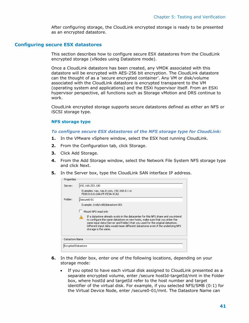
5. In the Server box, type the CloudLink SAN interface IP address.
6. In the Folder box, enter one of the following locations, depending on your
storage mode:
If you opted to have each virtual disk assigned to CloudLink presented as a
separate encrypted volume, enter /secure hostId-targetId/mnt in the Folder
box, where hostId and targetId refer to the host number and target
identifier of the virtual disk. For example, if you selected NFS/SMB (0:1) for the Virtual Device Node, enter /secure0-01/mnt. The Datastore Name can
Chapter 5: Testing and Verification
42
have any name. In CloudLink Center, the example volume would be displayed as 192.168.253.100:/secure0-01/mnt.
If you opted to merge all virtual disks assigned to CloudLink so that they are presented as a single encrypted volume, enter /secure0/mnt in the Folder
box.
7. Click Next and then click Finish to complete the datastore configuration.
You must format and configure access to the CloudLink secure storage before it can
be used. For information about formatting storage, see “Configuring CloudLink
Storage” in the earlier section named “Deploying vNodes for Datastore mode”. For information about configuring access, see the CloudLink SecureVSA VMware
VSphere Administration Guide.
iSCSI storage type
Before starting to configure the iSCSI datastore, you must do the following:
Power on and configure CloudLink Center or the CloudLink vNode for the
datastore.
In CloudLink Center, perform the following tasks:
change the storage type to iSCSI.
assign the storage license.
format the storage.
For information about assigning the storage license and formatting storage, see
“Configuring CloudLink Storage” in the earlier section named “Deploying vNodes for Datastore mode”. For information about changing the storage type, see the
Note: CloudLink’s iSCSI datastore mode isn’t compatible with storage assigned to
CloudLink via VMFS. To use iSCSI datastores, you must assign storage LUNs to CloudLink using RDM. Contact AFORE Support for more information.
For more information about best practices for iSCSI datastore operations, see the VMware document at: http://www.vmware.com/files/pdf/iSCSI_design_deploy.pdf
To configure secure ESX datastores of the iSCSI storage type:
1. In the VMware vSphere window, select the ESX host running the CloudLink
vNode.
2. From the Configuration tab, click Storage Adapters.
3. In the iSCSI Software Adapter list, right-click an adapter and click Properties.
4. On the Dynamic Discovery tab, click Add.
5. In the iSCSI Server box, type the CloudLink SAN IP address, and click OK.
This address is added to the list of dynamic targets.
6. On the Static Discovery tab, verify that the configured SAN IP address is listed.
7. Click Close.
8. When prompted to rescan, click Yes.
The iSCSI storage adapter is added to the list of iSCSI software adapters.
Chapter 5: Testing and Verification
43
9. From the Configuration tab, click Storage.
10. Click Add Storage.
11. Select Disk/LUN, and click Next.
12. Select the iSCSI storage volume, and click Next.
13. Ensure that the file system version is VMFS-5, and click Next.
14. Click Next.
15. For the datastore name, type any name that meaningfully identifies the datastore, and click Next.
16. Select the capacity, and click Next.
17. Click Finish.
The new datastore is added to the vSphere Datastores list.
Chapter 5: Testing and Verification
44
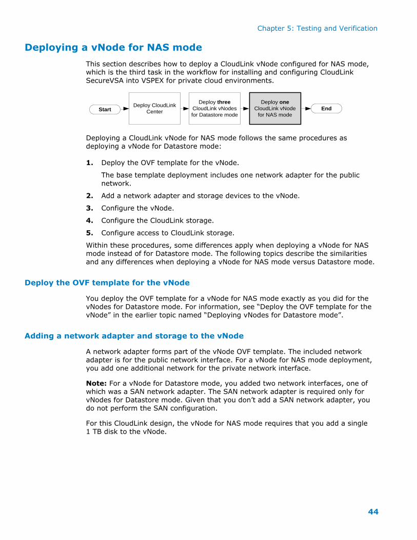
Deploying a vNode for NAS mode
This section describes how to deploy a CloudLink vNode configured for NAS mode, which is the third task in the workflow for installing and configuring CloudLink
SecureVSA into VSPEX for private cloud environments.
Start End
Deploy three
CloudLink vNodes
for Datastore mode
Deploy CloudLink
Center
Deploy one
CloudLink vNode
for NAS mode
Deploying a CloudLink vNode for NAS mode follows the same procedures as deploying a vNode for Datastore mode:
1. Deploy the OVF template for the vNode.
The base template deployment includes one network adapter for the public
network.
2. Add a network adapter and storage devices to the vNode.
3. Configure the vNode.
4. Configure the CloudLink storage.
5. Configure access to CloudLink storage.
Within these procedures, some differences apply when deploying a vNode for NAS mode instead of for Datastore mode. The following topics describe the similarities
and any differences when deploying a vNode for NAS mode versus Datastore mode.
Deploy the OVF template for the vNode
You deploy the OVF template for a vNode for NAS mode exactly as you did for the vNodes for Datastore mode. For information, see “Deploy the OVF template for the
vNode” in the earlier topic named “Deploying vNodes for Datastore mode”.
Adding a network adapter and storage to the vNode
A network adapter forms part of the vNode OVF template. The included network
adapter is for the public network interface. For a vNode for NAS mode deployment, you add one additional network for the private network interface.
Note: For a vNode for Datastore mode, you added two network interfaces, one of which was a SAN network adapter. The SAN network adapter is required only for
vNodes for Datastore mode. Given that you don’t add a SAN network adapter, you do not perform the SAN configuration.
For this CloudLink design, the vNode for NAS mode requires that you add a single
1 TB disk to the vNode.
Chapter 5: Testing and Verification
45
To add a network adapter for the private network:
1. From the VMware vSphere client, right-click a vNode and select Edit Settings to
access the Virtual Machine Properties window.
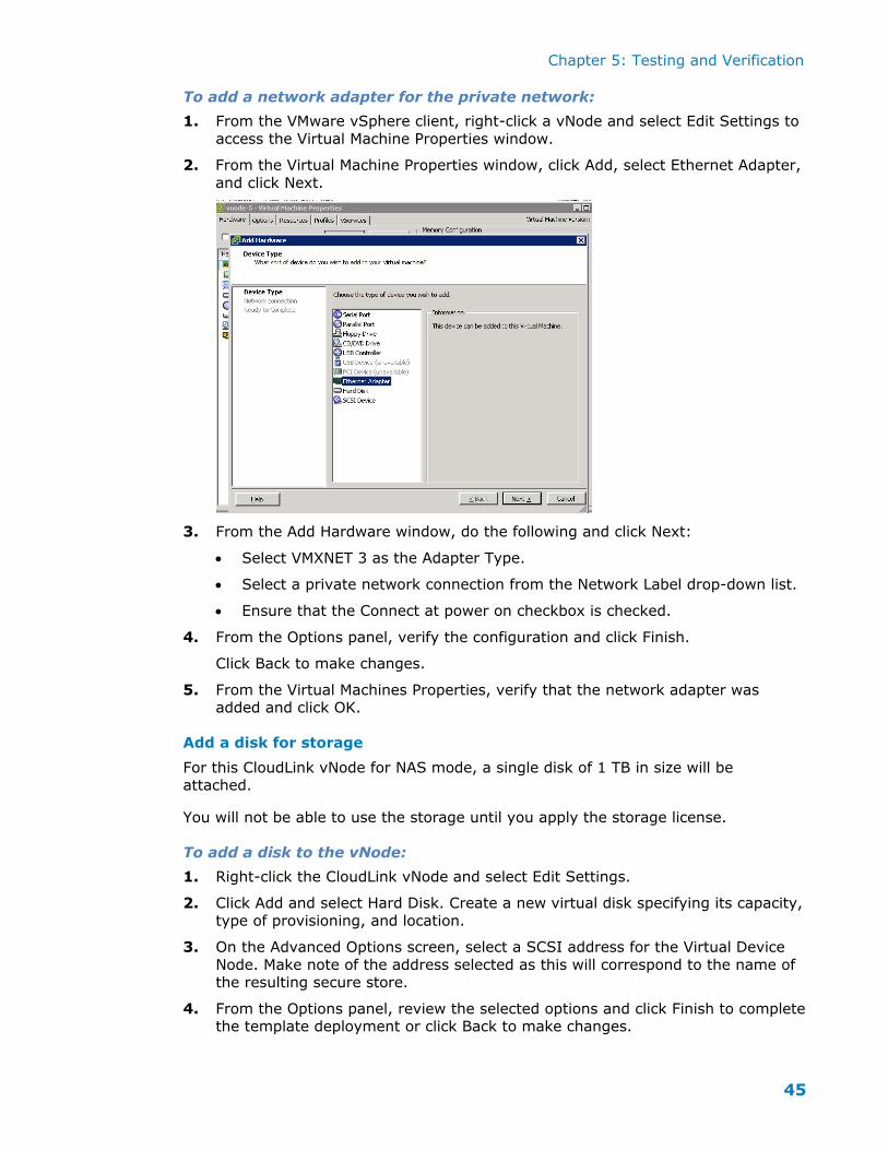
2. From the Virtual Machine Properties window, click Add, select Ethernet Adapter,
and click Next.
3. From the Add Hardware window, do the following and click Next:
Select VMXNET 3 as the Adapter Type.
Select a private network connection from the Network Label drop-down list.
Ensure that the Connect at power on checkbox is checked.
4. From the Options panel, verify the configuration and click Finish.
Click Back to make changes.
5. From the Virtual Machines Properties, verify that the network adapter was added and click OK.
Add a disk for storage
For this CloudLink vNode for NAS mode, a single disk of 1 TB in size will be attached.
You will not be able to use the storage until you apply the storage license.
To add a disk to the vNode:
1. Right-click the CloudLink vNode and select Edit Settings.
2. Click Add and select Hard Disk. Create a new virtual disk specifying its capacity,
type of provisioning, and location.
3. On the Advanced Options screen, select a SCSI address for the Virtual Device
Node. Make note of the address selected as this will correspond to the name of the resulting secure store.
4. From the Options panel, review the selected options and click Finish to complete the template deployment or click Back to make changes.
Chapter 5: Testing and Verification
46
5. From the Virtual Machines Properties, verify that the disk was added and click OK.
Configuring the vNode
You configure the vNode using the same process as for the vNode for Datastore
mode. For information, see “Configuring the vNode” in the earlier topic named “Deploying vNodes for Datastore mode”.
During the configuration, remember that this vNode only requires two network adapters (public and private). It does not require the SAN network adapter used by
a vNode for Datastore mode. For this vNode for NAS mode, the public network will be used for communication with CloudLink Center and the private network will be
used by VMs accessing the CloudLink encrypted NAS share (NFS, CIFS, iSCSI).
Configuring CloudLink Storage
You configure CloudLink storage for a vNode for NAS mode exactly as you did for
the vNodes for Datastore mode. For information about configuring CloudLink storage (including uploading and assigning a storage license, and formatting storage), see
“Configuring CloudLink Storage” in the earlier section named “Deploying vNodes for Datastore mode”.
Chapter 5: Testing and Verification
47
Configure access to CloudLink Storage
Once CloudLink storage has been formatted and is ready for use, access to the
secure storage must be defined in CloudLink.
You can configure, by IP address, which machines are granted access to the
CloudLink node’s secure storage over NFS/SMB. Note that storage can be configured for CloudLink Gateways and vNodes.
To configure access to storage:
1. Log in as a secadmin user.
2. From the Topology Tree, select the vNode used for the NAS mode.
3. Click the Storage tab then the Configuration tab.
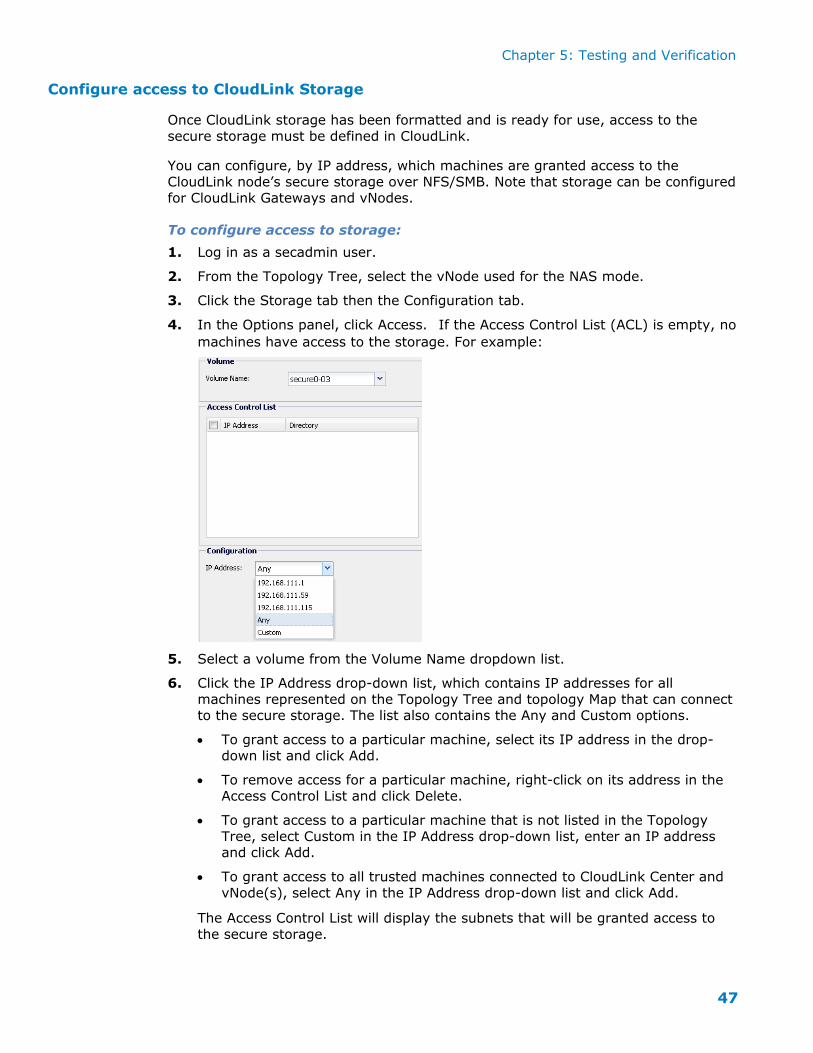
4. In the Options panel, click Access. If the Access Control List (ACL) is empty, no
machines have access to the storage. For example:
5. Select a volume from the Volume Name dropdown list.
6. Click the IP Address drop-down list, which contains IP addresses for all
machines represented on the Topology Tree and topology Map that can connect to the secure storage. The list also contains the Any and Custom options.
To grant access to a particular machine, select its IP address in the drop-down list and click Add.
To remove access for a particular machine, right-click on its address in the Access Control List and click Delete.
To grant access to a particular machine that is not listed in the Topology
Tree, select Custom in the IP Address drop-down list, enter an IP address and click Add.
To grant access to all trusted machines connected to CloudLink Center and
vNode(s), select Any in the IP Address drop-down list and click Add.
The Access Control List will display the subnets that will be granted access to
the secure storage.
Chapter 5: Testing and Verification
48
Note for Layer 3 network deployments: For deployments with CloudLink Center and multiple vNodes, devices connected to the private network interface
of one vNode will not be able to access secure storage hosted by other vNodes. Therefore, if Any is selected for a vNode, only the subnets of CloudLink Center
and that vNode’s private LAN interfaces will be displayed in the Access Control List.
7. Once access to a node’s secure storage has been granted, the storage is made available to those devices over NFS/SMB via the IP address of the private
network interface.
Configuring iSCSI access to secure storage
To access a vNode’s secure storage over iSCSI, you must configure CHAP credentials
for use in performing incoming access to the iSCSI target (that is, one-way CHAP
authentication).
If you wish to configure mutual CHAP authentication, you can optionally configure CHAP credentials for performing outgoing access from the NAS vNode to the iSCSI
initiator.
This section shows you how to:
Configure one-way CHAP authentication.
Configure mutual CHAP authentication.
Delete a CHAP credential from the Access Control List (ACL).
To configure one-way CHAP authentication:
1. Log in as a secadmin user.
2. From the Topology Tree, select the NAS vNode.
3. Click the Storage tab then the Configuration tab.
4. From the Options panel, click Access.
5. Select the encrypted volume for which you are configuring access from the
Volume Name dropdown list in the Volume panel.
6. If the Access Control List is empty, then there are no credentials configured for
accessing the iSCSI storage and the storage is therefore inaccessible.
7. Enter a CHAP user name in the User Name field and a corresponding secret in the Secret field. This user name and secret combination will be used to
authenticate the iSCSI initiator.
Chapter 5: Testing and Verification
49
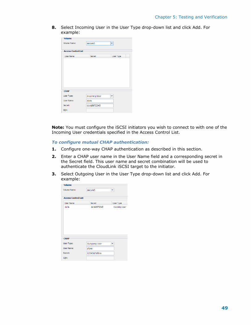
8. Select Incoming User in the User Type drop-down list and click Add. For example:
Note: You must configure the iSCSI initiators you wish to connect to with one of the
Incoming User credentials specified in the Access Control List.
To configure mutual CHAP authentication:
1. Configure one-way CHAP authentication as described in this section.
2. Enter a CHAP user name in the User Name field and a corresponding secret in
the Secret field. This user name and secret combination will be used to
authenticate the CloudLink iSCSI target to the initiator.
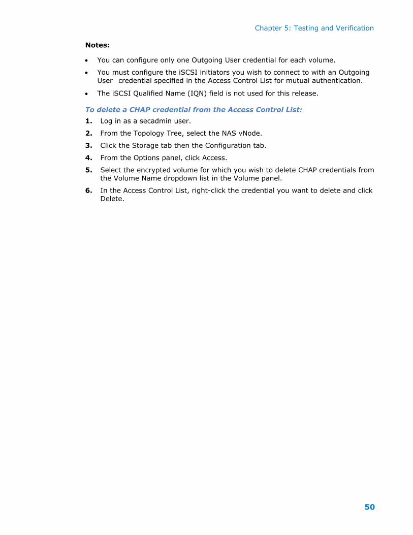
3. Select Outgoing User in the User Type drop-down list and click Add. For
example:
Chapter 5: Testing and Verification
50
Notes:
You can configure only one Outgoing User credential for each volume.
You must configure the iSCSI initiators you wish to connect to with an Outgoing
User credential specified in the Access Control List for mutual authentication.
The iSCSI Qualified Name (IQN) field is not used for this release.
To delete a CHAP credential from the Access Control List:
1. Log in as a secadmin user.
2. From the Topology Tree, select the NAS vNode.
3. Click the Storage tab then the Configuration tab.
4. From the Options panel, click Access.
5. Select the encrypted volume for which you wish to delete CHAP credentials from
the Volume Name dropdown list in the Volume panel.
6. In the Access Control List, right-click the credential you want to delete and click
Delete.
Chapter 5: Testing and Verification
51
Chapter 6 Testing and Verification
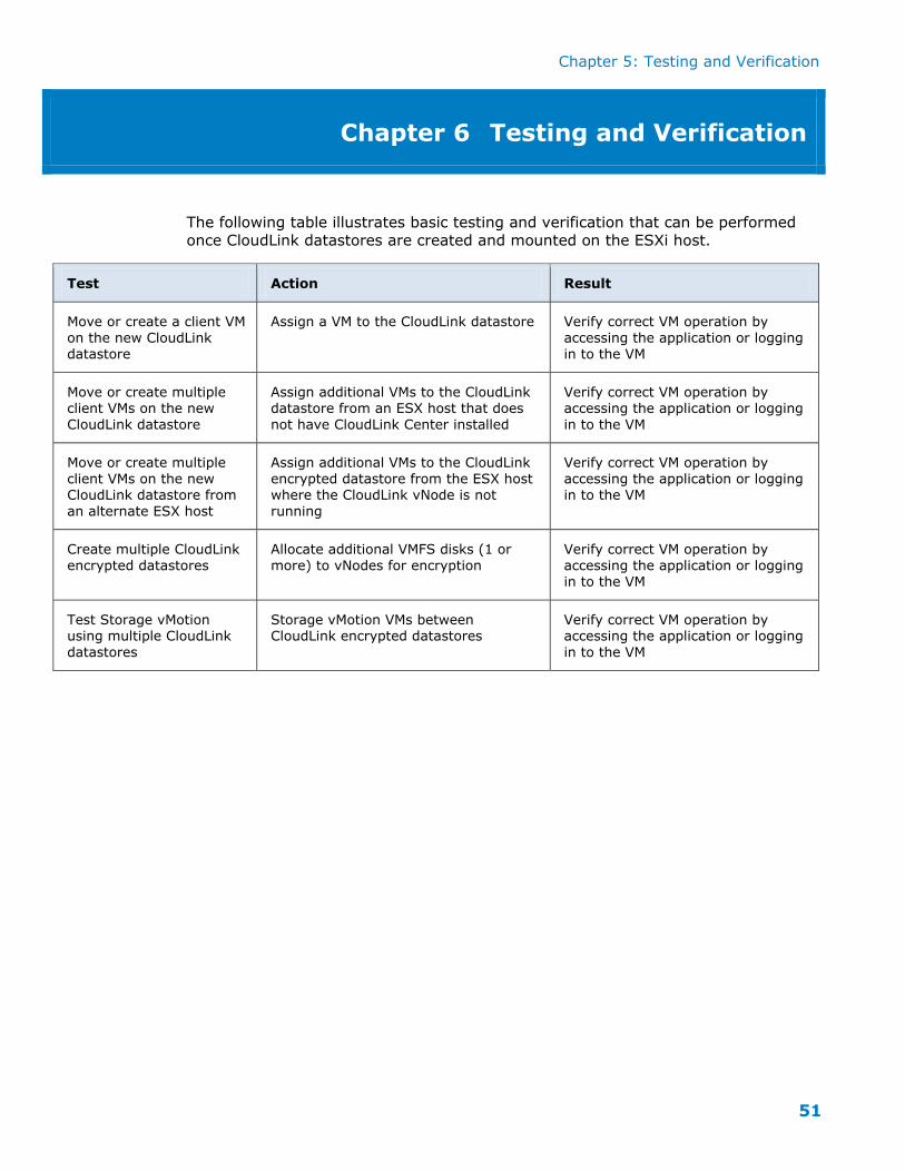
The following table illustrates basic testing and verification that can be performed
once CloudLink datastores are created and mounted on the ESXi host.
Test Action Result
Move or create a client VM
on the new CloudLink datastore
Assign a VM to the CloudLink datastore Verify correct VM operation by
accessing the application or logging in to the VM
Move or create multiple client VMs on the new
CloudLink datastore
Assign additional VMs to the CloudLink datastore from an ESX host that does
not have CloudLink Center installed
Verify correct VM operation by accessing the application or logging
in to the VM
Move or create multiple
client VMs on the new CloudLink datastore from
an alternate ESX host
Assign additional VMs to the CloudLink
encrypted datastore from the ESX host where the CloudLink vNode is not
running
Verify correct VM operation by
accessing the application or logging in to the VM
Create multiple CloudLink
encrypted datastores
Allocate additional VMFS disks (1 or
more) to vNodes for encryption
Verify correct VM operation by
accessing the application or logging in to the VM
Test Storage vMotion using multiple CloudLink
datastores
Storage vMotion VMs between CloudLink encrypted datastores
Verify correct VM operation by accessing the application or logging
in to the VM
Appendix A: Deployment Planning
52
Appendix A Pre-Deployment Checklist
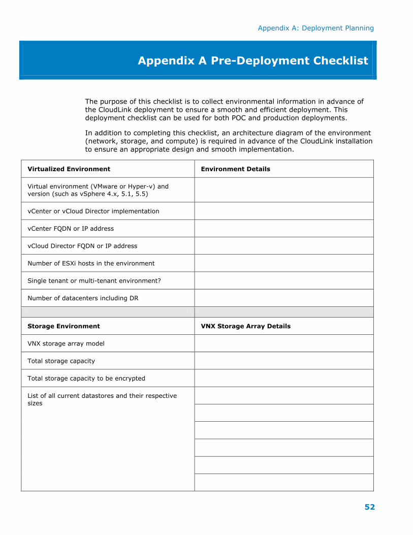
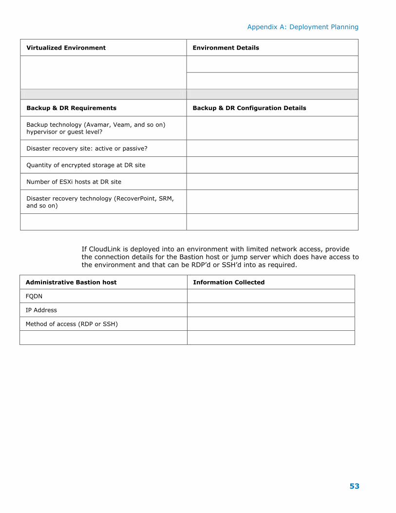
The purpose of this checklist is to collect environmental information in advance of
the CloudLink deployment to ensure a smooth and efficient deployment. This deployment checklist can be used for both POC and production deployments.
In addition to completing this checklist, an architecture diagram of the environment (network, storage, and compute) is required in advance of the CloudLink installation
to ensure an appropriate design and smooth implementation.
Virtualized Environment Environment Details
Virtual environment (VMware or Hyper-v) and
version (such as vSphere 4.x, 5.1, 5.5)
vCenter or vCloud Director implementation
vCenter FQDN or IP address
vCloud Director FQDN or IP address
Number of ESXi hosts in the environment
Single tenant or multi-tenant environment?
Number of datacenters including DR
Storage Environment VNX Storage Array Details
VNX storage array model
Total storage capacity
Total storage capacity to be encrypted
List of all current datastores and their respective
sizes
Appendix A: Deployment Planning
53
Virtualized Environment Environment Details
Backup & DR Requirements Backup & DR Configuration Details
Backup technology (Avamar, Veam, and so on)
hypervisor or guest level?
Disaster recovery site: active or passive?
Quantity of encrypted storage at DR site
Number of ESXi hosts at DR site
Disaster recovery technology (RecoverPoint, SRM,
and so on)
If CloudLink is deployed into an environment with limited network access, provide the connection details for the Bastion host or jump server which does have access to
the environment and that can be RDP’d or SSH’d into as required.
Administrative Bastion host Information Collected
FQDN
IP Address
Method of access (RDP or SSH)
Appendix A: Deployment Planning
54
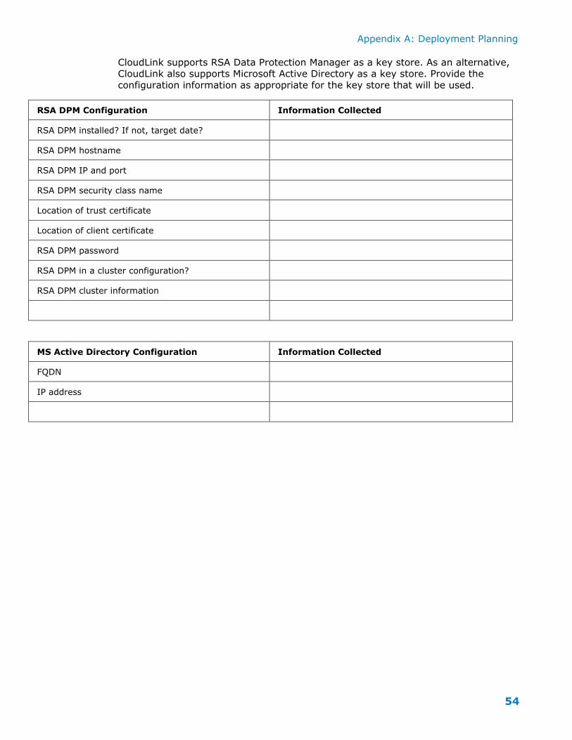
CloudLink supports RSA Data Protection Manager as a key store. As an alternative, CloudLink also supports Microsoft Active Directory as a key store. Provide the
configuration information as appropriate for the key store that will be used.
RSA DPM Configuration Information Collected
RSA DPM installed? If not, target date?
RSA DPM hostname
RSA DPM IP and port
RSA DPM security class name
Location of trust certificate
Location of client certificate
RSA DPM password
RSA DPM in a cluster configuration?
RSA DPM cluster information
MS Active Directory Configuration Information Collected
FQDN
IP address
Appendix A: Deployment Planning
55
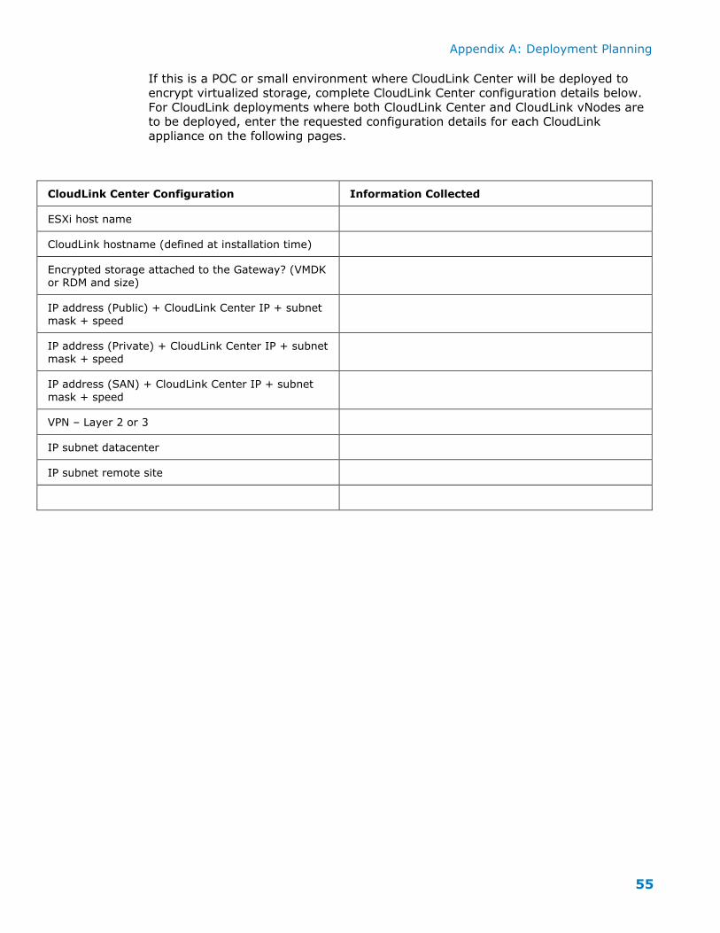
If this is a POC or small environment where CloudLink Center will be deployed to encrypt virtualized storage, complete CloudLink Center configuration details below.
For CloudLink deployments where both CloudLink Center and CloudLink vNodes are to be deployed, enter the requested configuration details for each CloudLink
appliance on the following pages.
CloudLink Center Configuration Information Collected
ESXi host name
CloudLink hostname (defined at installation time)
Encrypted storage attached to the Gateway? (VMDK
or RDM and size)
IP address (Public) + CloudLink Center IP + subnet
mask + speed
IP address (Private) + CloudLink Center IP + subnet mask + speed
IP address (SAN) + CloudLink Center IP + subnet
mask + speed
VPN – Layer 2 or 3
IP subnet datacenter
IP subnet remote site
Appendix A: Deployment Planning
56
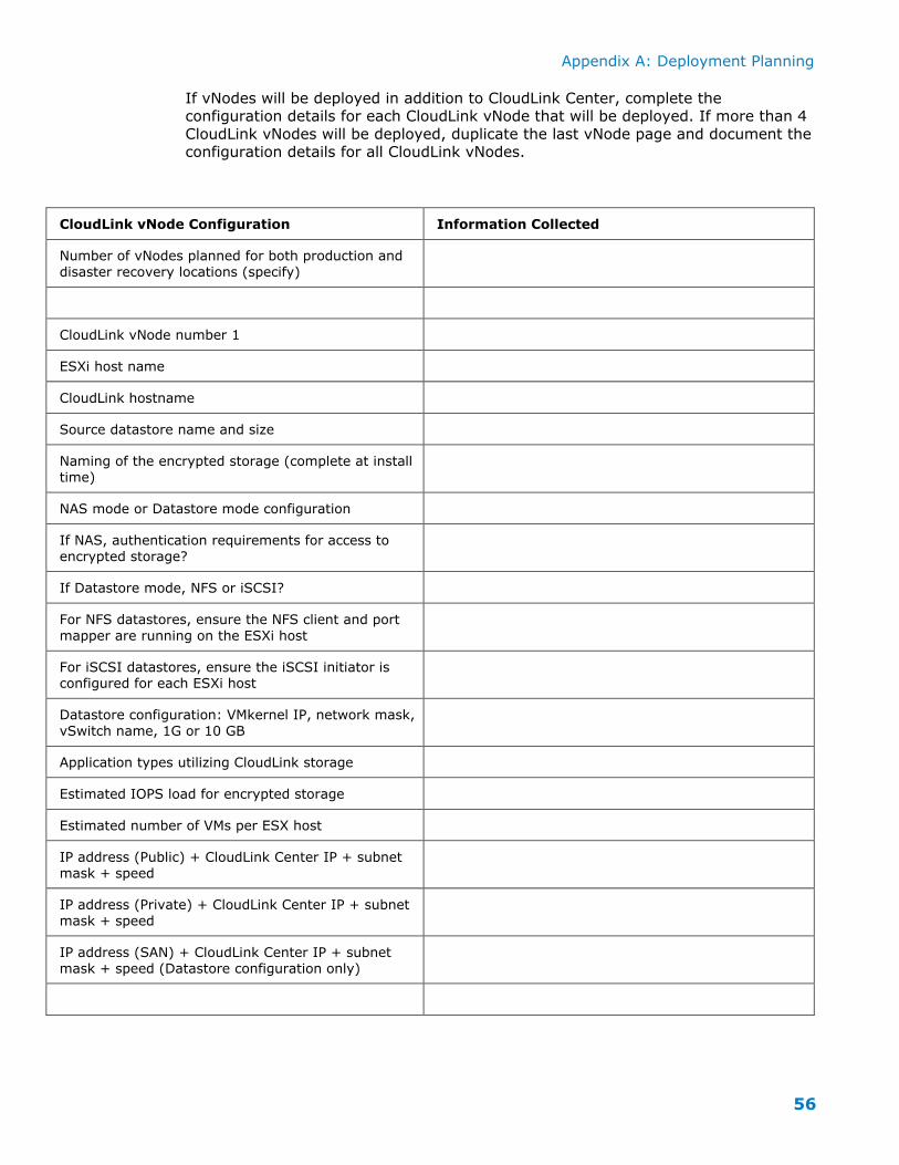
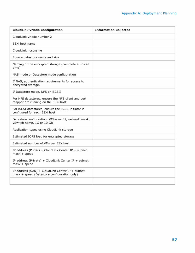
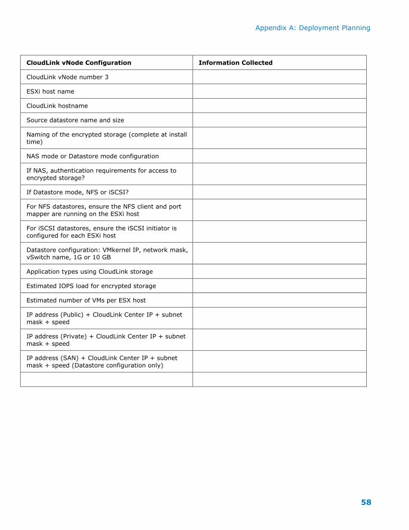
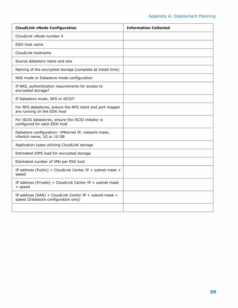
If vNodes will be deployed in addition to CloudLink Center, complete the configuration details for each CloudLink vNode that will be deployed. If more than 4
CloudLink vNodes will be deployed, duplicate the last vNode page and document the configuration details for all CloudLink vNodes.
CloudLink vNode Configuration Information Collected
Number of vNodes planned for both production and
disaster recovery locations (specify)
CloudLink vNode number 1
ESXi host name
CloudLink hostname
Source datastore name and size
Naming of the encrypted storage (complete at install
time)
NAS mode or Datastore mode configuration
If NAS, authentication requirements for access to
encrypted storage?
If Datastore mode, NFS or iSCSI?
For NFS datastores, ensure the NFS client and port
mapper are running on the ESXi host
For iSCSI datastores, ensure the iSCSI initiator is configured for each ESXi host


![Secure cloudlink...[November 2016] 412 million user accounts exposed revealing personal details [November 2016] EXPLOITING THE SINGLE BIGGEST RISK TO OUR DIGITAL LIFE It’s not a](https://static.documents.pub/doc/80x56/603baf747df7f50a7b0447aa/secure-cloudlink-november-2016-412-million-user-accounts-exposed-revealing.jpg)