23
technical data Air-cooled EWAQ-ACV3P EWYQ-ACV3P EEDEN09-401 Applied Systems

technical data
Air-cooled
EWAQ-ACV3P
EWYQ-ACV3P
EEDEN09-401
Applied System
s

technical data
Air-cooled
EWAQ-ACV3P
EWYQ-ACV3P
EEDEN09-401
Applied System
s
• Chillers • R-410A • EWAQ-EWYQ-ACV3P
• Hydronic Systems • Chillers4
Chille Hydron EWAQ-EW R-410A
Cooling only
Heating only
Heat pump
• Hydronic Systems • Chillers 5
• Chillers • R-410A • EWAQ-EWYQ-ACV3P
TABLE OF CONTENTSEWAQ-EWYQ-ACV3P
1 Features . . . . . . . . . . . . . . . . . . . . . . . . . . . . . . . . . . . . . . . . . . . . . . . . . . . . . . . . . . . . . 6
2 Specification text . . . . . . . . . . . . . . . . . . . . . . . . . . . . . . . . . . . . . . . . . . . . . . . . . . . 7
3 Specifications . . . . . . . . . . . . . . . . . . . . . . . . . . . . . . . . . . . . . . . . . . . . . . . . . . . . . . . 9 Technical Specifications EWAQ-ACV3P . . . . . . . . . . . . . . . . . . . . . . . . . . . . 9 Technical Specifications EWYQ-ACV3P . . . . . . . . . . . . . . . . . . . . . . . . . . . 10 Electrical Specifications EWAQ-ACV3P . . . . . . . . . . . . . . . . . . . . . . . . . . . . 11 Electrical Specifications EWYQ-ACV3P . . . . . . . . . . . . . . . . . . . . . . . . . . . . 12
4 Options . . . . . . . . . . . . . . . . . . . . . . . . . . . . . . . . . . . . . . . . . . . . . . . . . . . . . . . . . . . . . 13
5 Capacity tables . . . . . . . . . . . . . . . . . . . . . . . . . . . . . . . . . . . . . . . . . . . . . . . . . . . . 14Cooling/Heating capacity tables . . . . . . . . . . . . . . . . . . . . . . . . . . . . . . . . . . . . 14
6 Dimensional drawing & centre of gravity . . . . . . . . . . . . . . . . . . . . . . . 15Dimensional drawing . . . . . . . . . . . . . . . . . . . . . . . . . . . . . . . . . . . . . . . . . . . . . . . . 15Centre of gravity . . . . . . . . . . . . . . . . . . . . . . . . . . . . . . . . . . . . . . . . . . . . . . . . . . . . 16
7 Piping diagram. . . . . . . . . . . . . . . . . . . . . . . . . . . . . . . . . . . . . . . . . . . . . . . . . . . . . 17
8 Wiring diagram. . . . . . . . . . . . . . . . . . . . . . . . . . . . . . . . . . . . . . . . . . . . . . . . . . . . . 18Wiring diagram . . . . . . . . . . . . . . . . . . . . . . . . . . . . . . . . . . . . . . . . . . . . . . . . . . . . . . 18
9 Sound data . . . . . . . . . . . . . . . . . . . . . . . . . . . . . . . . . . . . . . . . . . . . . . . . . . . . . . . . . 19Sound pressure spectrum . . . . . . . . . . . . . . . . . . . . . . . . . . . . . . . . . . . . . . . . . . . 19Sound power spectrum . . . . . . . . . . . . . . . . . . . . . . . . . . . . . . . . . . . . . . . . . . . . . 21
10 Operation range . . . . . . . . . . . . . . . . . . . . . . . . . . . . . . . . . . . . . . . . . . . . . . . . . . . 22
11 Hydraulic performance. . . . . . . . . . . . . . . . . . . . . . . . . . . . . . . . . . . . . . . . . . . . 23Static pressure drop unit . . . . . . . . . . . . . . . . . . . . . . . . . . . . . . . . . . . . . . . . . . . . 23

• Chillers • R-410A • EWAQ-EWYQ-ACV3P
11
• Hydronic Systems • Chillers6
1 Features
Chillers Hydronic Sys EWAQ-EWYQ-ACV R-410A • Inverter chiller
• Optimised for use with R-410A
• Daikin swing compressor
• Integrated hydronics
• No buffer tank needed
• Advanced control possibilities
• Precise temperature control
• Single phase power supply

3
12
• Hydronic Systems • Chillers 7
• Chillers • R-410A • EWAQ-EWYQ-ACV3P
2 Specification text
Unit construction: DAIKIN inverter controlled mini chiller with extremely compact, modular and weatherproof heat pump design for outdoor application IP 24 that meets ISO 9001 standards. The unit is ready for connection and has been designed for air conditioning as well as process cooling applications. The use of state-of-the-art technologies and high quality materials ensures efficiency, reliability and extended service life. Each DAIKIN chiller is subjected to a factory-side test run under standard conditions lasting several hours.
Casing / Colour: Powder coated, galvanised steel plate. Fully factory assembled on a base frame. Ivory white / Munsell code 5Y7.5/1
Number of refrigeration cycles: Unit size 005 - 007 single circuit.
Compressor: Fully hermetical inverter controlled swing compressor optimised for R410A, high performance, very smooth operation, low noise, highly efficient. On the suction side it is protected against water hammer by a large accumulator. The refrigerant compressor is equipped with an overcurrent relay and a thermal protection.
Condenser: Each refrigeration cycle has a high-performance Cu/AL heat exchanger. Consisting of internally drawn Cu pipe (Hi -X) guaranteeing excellent heat transmission and optimal oil transportation. Integrated subcooler for increased performance. Increased heat transmission surface with continuously laminated wafer fins results in reduced sound levels and compact dimensions. An polyacryl coating permanently protects the fins from corrosion thereby extending the field of application of this device.
Fans:Axial fans with thermal-protection drive motor 230 V/50 Hz. For condenser pressure control the fan is inverter controlled. The motor is statically and dynamically balanced and the bearing is realized in a way that vibration is absorbed. A close meshed fan grille protects the fan against external forces. Air suction is realized via the condenser.
Refrigeration cycle: Consists of Cu tube with all necessary cooling fittings such as: 4-port valve, service valves, filter, muffler, EEV, FL seperator. The refrigeration cycle is subject to factory pressure and leak testing, is cleaned, dried, evacuated and supplied with the R410A safety refrigerant and oil charged ready for operation.
Evaporator: R410A optimised DX counter flow plate heat exchanger made of stainless steel, plates brazed gastight with copper, for water and glycol mixtures. For optimum capacity of the complete heat transmission surface a special refrigerant distribution system has been incorporated into each plate duct. This further increases the efficiency and provides a stable control behavior in the heat exchanger. In order to prevent loss of heat the plate heat exchanger has a diffusion-proof heat insulation. To prevent freezing damage when ambient temperature is low the plate heat exchanger is equipped with a heater.
Hydraulic Module: The cooler tubes are made of corrosion-resistant brass and the heat exchanger is equipped with a strainer and an electromechanical flow controller. The unit also comes with all hydronic components needed for operation. This includes a circulation pump, expansion vessel, manometer, shut-off valves, safety valve, purge, charge and drainage valve, maintenance connections and compensation valve.
Switching and control device: Micro computer control with integrated self diagnosis. Complete electric wiring with terminal blocks for feed-in, main switch and connection to external control panel.
Remark:

• Chillers • R-410A • EWAQ-EWYQ-ACV3P
12
• Hydronic Systems • Chillers8
2 Specification text
The connection wire for the external control panel (2x 0,75–1 mmm2) has to be ordered separately. The maximum distance is 500 m.
External DDC control panel: The units are supplied with a digital controller that allows for a user friendly set-up, operation and maintenance of the unit.
The electronics support for example the following functions:
On/OffCooling/heating (heat pump only) Continuous condenser pressure control „Silent Mode“ night setback Allocation of the target value and the switching hysteresis Automatic sliding target value shift Cold water flow control Timer / Date functionality Schedule timer Error code retrieval

3
13
• Hydronic Systems • Chillers 9
• Chillers • R-410A • EWAQ-EWYQ-ACV3P
3 Specifications
3-1 TECHNICAL SPECIFICATIONS EWAQ-ACV3P EWAQ005ACV3P EWAQ006ACV3P EWAQ007ACV3P
Capacity (Eurovent) Cooling Minimum kW 4.01 4.01 4.01Nominal kW 5.2 6.0 7.1Maximum kW 5.2 6.0 7.1
Nominal input (Eurovent)
Cooling kW 1.89 2.35 2.95
EER 2.75 2.55 2.41Casing Colour Ivory white/Munsell code 5Y7.5/1
Material Polyester painted steel plateDimensions Unit Height mm 805 805 805
Width mm 1190 1190 1190Depth mm 360 360 360
Unit with packing Height mm 915 915 915Width mm 1265 1265 1265Depth mm 442 442 442
Weight Unit kg 100 100 100Operating Weight kg 104 104 104Gross weight kg 108 108 108
Water Heat Exchanger
Type Brased plateFilter Type Brass Y-strainer
Diameter perforations
mm 1 1 1
Minimum water volume in the system l 10 10 10Water flow rate Min l/min 12 12 12Nominal Water Flow Cooling l/min 14.9 17.2 20.4Insulation material Polyethylene foamModel Quantity 1 1 1
Model ACH30-48Air heat exchanger Type Tube type
Rows 2 2 2Stages 32 32 32Fin Pitch mm 1.8 1.8 1.8
Pump Type Water cooledQuantity 1 1 1Model RS 25/7 3 PL 130 3Nominal static height unit
Heating kPa 49.4 45.1 38.3
Hydraulic components
Antifreeze heater W 75 75 75Expansion vessel Volume l 6 6 6
Pre-pressure bar 1 1 1Water filter inch 1’’Safety valve bar 3 3 3
Fan Type PropellerModel Quantity 1 1 1
Motor Output W 53 53 53Discharge direction Horizontal
Compressor Type Hermetically sealed swing compressorRefrigerant oil type FVC50KRefrigerant oil charge l 0.75 0.75 0.75Model Quantity 1 1 1
Model 2YC63BXD#CSound level Sound Power Cooling dBA 62 62 63
Sound Pressure Cooling dBA 48 48 50Refrigerant circuit Refrigerant type R-410A
Refrigerant charge kg 1.7 1.7 1.7No of circuits 1 1 1Refrigerant control Inverter

• Chillers • R-410A • EWAQ-EWYQ-ACV3P
13
• Hydronic Systems • Chillers10
3 Specifications
Piping connections Water heat exchanger inlet / outlet 1’’ MBSPWater heat exchanger drain hose nipple 1/2’’ FBSP
Notes Nominal cooling capacity is based on the following conditions: evaporator: 12°C/7°C; ambient: 35°CThe sound pressure level is measured via a microphone at a certain distance from the unit. It is a
relative value, depending on the distance and acoustic environment.
3-2 TECHNICAL SPECIFICATIONS EWYQ-ACV3P EWYQ005ACV3P EWYQ006ACV3P EWYQ007ACV3P
Capacity (Eurovent) Cooling Minimum kW 4.01 4.01 4.01Nominal kW 5.2 6.0 7.1Maximum kW 5.2 6.0 7.1
Heating Minimum kW 4.09 4.09 4.09Nominal kW 5.65 6.35 7.75Maximum kW 6.83 8.13 8.73
Capacity Heating Minimum kW 4.5 4.5 4.5Nominal kW 6.1 6.8 8.2Maximum kW 7.27 8.58 9.18
Nominal input (Eurovent)
Cooling kW 1.89 2.35 2.95Heating kW 1.97 2.24 2.83
Nominal input Heating kW 1.60 1.84 2.36EER 2.75 2.55 2.41COP (Eurovent) 2.87 2.83 2.74COP 3.81 3.7 3.47Casing Colour Ivory white/Munsell code 5Y7.5/1
Material Polyester painted steel plateDimensions Unit Height mm 805 805 805
Width mm 1190 1190 1190Depth mm 360 360 360
Unit with packing Height mm 915 915 915Width mm 1265 1265 1265Depth mm 442 442 442
Weight Unit kg 100 100 100Operating Weight kg 104 104 104Gross weight kg 108 108 108
Water Heat Exchanger
Type Brased plateFilter Type Brass Y-strainer
Diameter perforations
mm 1 1 1
Minimum water volume in the system l 10 10 10Water flow rate Min l/min 12 12 12Nominal Water Flow Cooling l/min 14.9 17.2 20.4
Heating l/min 17.5 19.5 23.5Insulation material Polyethylene foamModel Quantity 1 1 1
Model ACH30-48Air heat exchanger Type Tube type
Rows 2 2 2Stages 32 32 32Fin Pitch mm 1.8 1.8 1.8
Pump Type Water cooledQuantity 1 1 1Model RS 25/7 3 PL 130 3Nominal static height unit
Heating kPa 49.4 45.1 38.3Heating kPa 44.5 40.3 30.7
Hydraulic components
Antifreeze heater W 75 75 75Expansion vessel Volume l 6 6 6
Pre-pressure bar 1 1 1Water filter inch 1’’Safety valve bar 3 3 3
3-1 TECHNICAL SPECIFICATIONS EWAQ-ACV3P EWAQ005ACV3P EWAQ006ACV3P EWAQ007ACV3P

3
13
• Hydronic Systems • Chillers 11
• Chillers • R-410A • EWAQ-EWYQ-ACV3P
3 Specifications
Fan Type PropellerModel Quantity 1 1 1
Motor Output W 53 53 53Discharge direction Horizontal
Compressor Type Hermetically sealed swing compressorRefrigerant oil type FVC50KRefrigerant oil charge l 0.75 0.75 0.75Model Quantity 1 1 1
Model 2YC63BXD#CSound level Sound Power Cooling dBA 62 62 63
Sound Pressure Cooling dBA 48 48 50Heating dBA 48 48 49
Refrigerant circuit Refrigerant type R-410ARefrigerant charge kg 1.7 1.7 1.7No of circuits 1 1 1Refrigerant control Inverter
Piping connections Water heat exchanger inlet / outlet 1’’ MBSPWater heat exchanger drain hose nipple 1/2’’ FBSP
Notes Nominal cooling capacity is based on the following conditions: evaporator: 12°C/7°C; ambient: 35°CNominal heating capacity, heating power input and COP at non-Eurovent conditions: ambient 7°CDB/
6CWB; condensor 30°C/35°C.Nominal heating capacity, heating power input and COP at Eurovent conditions: ambient 7°CDB/
6CWB; condensor 40°C/45°C.The sound pressure level is measured via a microphone at a certain distance from the unit. It is a
relative value, depending on the distance and acoustic environment.
3-3 ELECTRICAL SPECIFICATIONS EWAQ-ACV3P EWAQ005ACV3P EWAQ006ACV3P EWAQ007ACV3P
Power Supply Name V3Phase 1~Frequency Hz 50 50 50Voltage V 230 230 230Voltage Tolerance Minimum % -10%
Maximum % +10%Unit Maximum Running Current A 17.3 17.3 17.3
Recommended fuses according to IEC standard 269-2 20 20 20Fan Quantity 1 1 1
Phase 1~Voltage V 230 230 230
Pump Phase 1~Power input kW 0.13 0.13 0.13Voltage V 230 230 230Maximum Running Current A 0.58 0.58 0.58Speed Minimum rpm 1050 1050 1050
Nominal rpm 2250 2250 2250Maximum rpm 2450 2450 2450
Evaporator Heater Tape
Supply Voltage V 230 230 230Capacity W 75 75 75Voltage Tolerance Minimum % -10%
Maximum % +10%Recommended fuses 20A
Notes Fuse value valid for complete unit
3-2 TECHNICAL SPECIFICATIONS EWYQ-ACV3P EWYQ005ACV3P EWYQ006ACV3P EWYQ007ACV3P

• Chillers • R-410A • EWAQ-EWYQ-ACV3P
13
• Hydronic Systems • Chillers12
3 Specifications
3-4 ELECTRICAL SPECIFICATIONS EWYQ-ACV3P EWYQ005ACV3P EWYQ006ACV3P EWYQ007ACV3P
Power Supply Name V3Phase 1~Frequency Hz 50 50 50Voltage V 230 230 230Voltage Tolerance Minimum % -10%
Maximum % +10%Unit Maximum Running Current A 19 19 19
Recommended fuses according to IEC standard 269-2 20 20 20Fan Quantity 1 1 1
Phase 1~Voltage V 230 230 230
Pump Phase 1~Power input kW 0.13 0.13 0.13Voltage V 230 230 230Maximum Running Current A 0.58 0.58 0.58Speed Minimum rpm 1050 1050 1050
Nominal rpm 2250 2250 2250Maximum rpm 2450 2450 2450
Evaporator Heater Tape
Supply Voltage V 230 230 230Capacity W 75 75 75Voltage Tolerance Minimum % -10%
Maximum % +10%Recommended fuses 25A
Notes Fuse value valid for complete unit

3
14
• Hydronic Systems • Chillers 13
• Chillers • R-410A • EWAQ-EWYQ-ACV3P
4 Options
Capacity: 5 - 7.1 kW
Modelnumber
EWAQ005A*V3P EWYQ005A*V3PEWAQ006A*V3P EWYQ006A*V3PEWAQ007A*V3P EWYQ007A*V3P
Option number Option description (On) Unit size Availability
EWAQ005A*V3P EWAQ006A*V3P EWAQ007A*V3P EWYQ005A*V3P EWYQ006A*V3P EWYQ007A*V3P
Standard unit
Available options
OP10 Evaporator heatertape -H- V V V V V V Factory mounted
3TW57539-5
NotesV Available

• Chillers • R-410A • EWAQ-EWYQ-ACV3P
15
• Hydronic Systems • Chillers14
5 Capacity tables5 - 1 Cooling/Heating capacity tablesCOOLING
Model Tamb (°C) 20 25 30 35 40 43LWE (°C) CC PI CC PI CC PI CC PI CC PI CC PI
HEATING
Model LWC 30 35 40 45 50Tamb HC PI HC PI HC PI HC PI HC PI
3TW57532-1
SYMBOLSCC : Cooling capacity at maximum operating frequency, measured
acc. Eurovent 6/C/003-2006 (kW)
HC : Heating capacity at maximum operating frequency,measured acc. Eurovent 6/C/003-2006 (kW)
PI : Power input (kW)
LWE : Leaving evaporator water temperature (°C)
LWC : Leaving Water Condensor temperature (°C)
Tamb : Ambient temperature (°C) RH=85%
Conditions1 Cooling capacity
Capacity is according to Eurovent rating standard 6/C/003-2006 andvalid for chilled water range Dt = 3∼8°C
2 Heating capacityCapacity is according to Eurovent rating standard 6/C/003-2006 andvalid for chilled water range Dt = 3∼8°C
3 Power inputPower input is total input according to Eurovent rating standard6/C/003-2006
Note:The heating capacity and power input in the table has to be multiplied by the correctionfactor CFas listed in the table below to obtain the integrated heating capacity and power input.The integrated heating capacity and power input, is the average heating capacity and powerinput during 1 cycle. (from end of defrost till end of the next defrost).
Tamb -15 -10 -7 -2 2 7CF for HC 0.89 0,89 0,88 0,87 0,86 1,00CF for PI 0.95 0,95 0,94 0,93 0,92 1,00
3
16
• Hydronic Systems • Chillers 15
• Chillers • R-410A • EWAQ-EWYQ-ACV3P
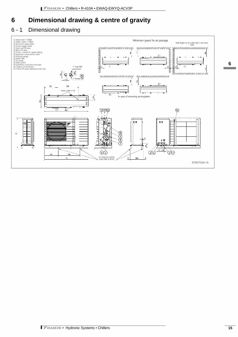
6 Dimensional drawing & centre of gravity6 - 1 Dimensional drawing
3TW57534-1A
j1 Water inlet 1’’ MBSPj2 Water outlet 1’’ MBSPj3 Remocom cable intakej4 Power supply intakej5 Drain and fill valvej6 Blow off valvej7 Pump + switch for speed settingj8 Expansion vessel service valvej9 Pressure gaugej10 Water filterj11 Air purgej12 Main switchj13 Switchbox connection terminalsj14 Outdoor air thermistorj15 2 Shut off valves (delivered with unit)
1’’ female BSP
1’’ male BSP
Drain outlet J18
In case of removing serviceplates
Minimum space for air passageWall height on air outlet side = less than
1200
4 x holes for anchorbolts (M8 or M10)
• Chillers • R-410A • EWAQ-EWYQ-ACV3P
16
• Hydronic Systems • Chillers16
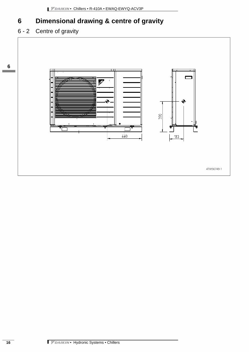
6 Dimensional drawing & centre of gravity6 - 2 Centre of gravity
4TW56749-1
3
17
• Hydronic Systems • Chillers 17
• Chillers • R-410A • EWAQ-EWYQ-ACV3P
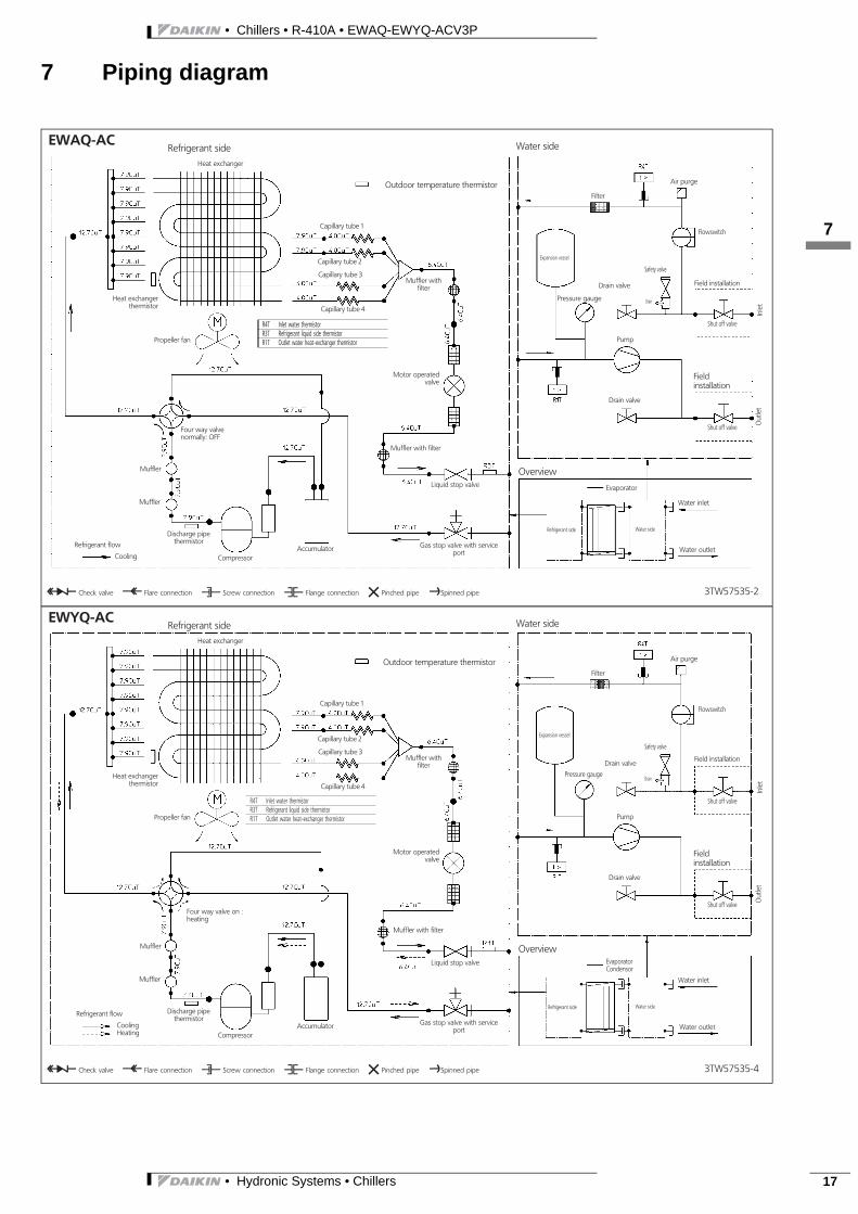
7 Piping diagram
3TW57535-2
EWAQ-AC
Outdoor temperature thermistor
Heat exchanger
Propeller fan
Capillary tube 1
Liquid stop valve
Gas stop valve with serviceport
Compressor
Capillary tube 3
Refrigerant flow
Cooling
Discharge pipethermistor
Heat exchangerthermistor
Capillary tube 2
Capillary tube 4
Muffler withfilter
Motor operatedvalve
Filter
Refrigerant side
Muffler
Four way valvenormally: OFF
Muffler
Accumulator
Air purge
Expansion vessel
Pressure gauge
Drain valve
Drain
Safety valve
Flowswitch
Field installation
Shut off valve
Fieldinstallation
Shut off valve
Pump
Drain valve
Evaporator
Refrigerant side Water side
Water inlet
Water outlet
Overview
Water side
Out
let
Inle
t
O Check valve L Flare connection M Screw connection N Flange connection Z Pinched pipe PSpinned pipe
Muffler with filter
R4T Inlet water thermistorR3T Refrigerant liquid side thermistorR1T Outlet water heat-exchanger thermistor
3TW57535-4
EWYQ-AC
Outdoor temperature thermistor
Heat exchanger
Propeller fan
Capillary tube 1
Liquid stop valve
Gas stop valve with serviceport
Compressor
Capillary tube 3
Refrigerant flow
CoolingHeating
Discharge pipethermistor
Heat exchangerthermistor
Capillary tube 2
Capillary tube 4
Muffler withfilter
Motor operatedvalve
Filter
Refrigerant side
Muffler
Four way valve on :heating
Muffler
Accumulator
Air purge
Expansion vessel
Pressure gauge
Drain valve
Drain
Safety valve
Flowswitch
Field installation
Shut off valve
Fieldinstallation
Shut off valve
Pump
Drain valve
EvaporatorCondensor
Refrigerant side Water side
Water inlet
Water outlet
Overview
Water side
Out
let
Inle
t
O Check valve L Flare connection M Screw connection N Flange connection Z Pinched pipe PSpinned pipe
R4T Inlet water thermistorR3T Refrigerant liquid side thermistorR1T Outlet water heat-exchanger thermistor
Muffler with filter

• Chillers • R-410A • EWAQ-EWYQ-ACV3P
18
• Hydronic Systems • Chillers18
8 Wiring diagram8 - 1 Wiring diagram
3TW57536-1A
EWAQ/EWYQ AC
Q1Dl Earth leakage protectorTR1 Transformer 24V for PCBR4T Inlet water thermistorR3T Refrigerant liquid side thermistorR1T Outlet water heat exchangerS1L FlowswitchM1P PumpA2P Remocom PCB (indoor)A1P Main PCBS1M MainswitchFU1 Fuse 3.15A T 250VFU2 Fuse 5A 250VX1A,X2A ConnectorX4A,X5A ConnectorX7A,X8A ConnectorX10A,X15A ConnectorX17A,X18A ConnectorX19A,X20A ConnectorE5H HeatertapeE6H Heatertape (Field supply)SS2 DipswitchK1M RelayX3M Terminal strip
Userinterface
Power supply
Sheet metal
(Outdoor) (Discharge)(Condensor)
see note 6
Notes:1 This wiring diagram only applies to the outdoor unit2 : Field wiring3 : Terminal strip : Connector : Terminal
: Protective earth4 Do not operate the unit by short-circuiting protection devices Q1L, S1L5 BLK: Black / WHT: White / RED: Red / BLU: Blue / PINK: Pink / YLW: Yellow / BRN:
Brown / GRY: Grey / GRN: Green / ORG: Orange / VIO: Violet6 When the remote ON/OFF, remote heating and remote cooling function is not
used, apply wire bridge between terminals 8, 9 and 10.
Z1C∼Z4C Ferrite coreX1M,X2M Terminal stripY1E Electronic expansion valve coilV2,V3,V5,V6,V11 VaristorSA2 Surge arresterFU1 Fuse 30A 250VFU2 Fuse 3.15A 250VFU3 Fuse 3.15A 250VAC1,AC2U,V,W,X11A ConnectorE1,E2HR1,HR2 ConnectorMRM10,MRM20 Magnetic relayMRC/W Magnetic relayR1T∼R3T ThermistorS2∼S102 ConnectorLED A Pilot lamp
L LiveN NeutralSW1 Forced operation on/off SW (SW1)SW4 Local setting SW (SW4)M1C Compressor motorsM1F Fan motorL1R ReactorQ1L Overload protectorPM1 Power modulePCB1,2 Printed circuit boardY1R Reversing solenoid valve coilSheet metal Terminal strip fixed plate
Option
Field wiring
PCB
Wire colour
OP10(Option heatertape)
Remote
heat
ing
cool
ing
On/
Off

3
19
• Hydronic Systems • Chillers 19
• Chillers • R-410A • EWAQ-EWYQ-ACV3P
9 Sound data9 - 1 Sound pressure spectrum
3TW57537-1
Soun
dpr
essu
rele
vel(
dB)
Octave band center frequency (Hz)
EWAQ005ACEWYQ005AC (Cooling)
NOTES1 Data is valid at free field condition (measured in a
semi-anachoic room)2 dB(A) = A-weighted sound pressure level (A-scale
according to IEC)3 Reference acoustic pressure 0dB = 20μPa4 If sound is measured under actual installation
conditions, the measured value will be higher due toenvironmental noise and sound reflections.
Location of microphone
Microphone
Coil
3TW57537-1
Soun
dpr
essu
rele
vel(
dB)
Octave band center frequency (Hz)
EWAQ006ACEWYQ006AC (Cooling)
NOTES1 Data is valid at free field condition (measured in a
semi-anachoic room)2 dB(A) = A-weighted sound pressure level (A-scale
according to IEC)3 Reference acoustic pressure 0dB = 20μPa4 If sound is measured under actual installation
conditions, the measured value will be higher due toenvironmental noise and sound reflections.
Location of microphone
Microphone
Coil
3TW57537-1
Soun
dpr
essu
rele
vel(
dB)
Octave band center frequency (Hz)
EWAQ007ACEWYQ007AC (Cooling)
NOTES1 Data is valid at free field condition (measured in a
semi-anachoic room)2 dB(A) = A-weighted sound pressure level (A-scale
according to IEC)3 Reference acoustic pressure 0dB = 20μPa4 If sound is measured under actual installation
conditions, the measured value will be higher due toenvironmental noise and sound reflections.
Location of microphone
Microphone
Coil
3TW57537-2
Soun
dpr
essu
rele
vel(
dB)
Octave band center frequency (Hz)
EWYQ005AC (Heating)
NOTES1 Data is valid at free field condition (measured in a
semi-anachoic room)2 dB(A) = A-weighted sound pressure level (A-scale
according to IEC)3 Reference acoustic pressure 0dB = 20μPa4 If sound is measured under actual installation
conditions, the measured value will be higher due toenvironmental noise and sound reflections..
Location of microphone
Microphone
Coil

• Chillers • R-410A • EWAQ-EWYQ-ACV3P
19
• Hydronic Systems • Chillers20
9 Sound data9 - 1 Sound pressure spectrum
3TW57537-2
Soun
dpr
essu
rele
vel(
dB)
Octave band center frequency (Hz)
EWYQ006AC (Heating)
NOTES1 Data is valid at free field condition (measured in a
semi-anachoic room)2 dB(A) = A-weighted sound pressure level (A-scale
according to IEC)3 Reference acoustic pressure 0dB = 20μPa4 If sound is measured under actual installation
conditions, the measured value will be higher due toenvironmental noise and sound reflections..
Location of microphone
Microphone
Coil
3TW57537-2
Soun
dpr
essu
rele
vel(
dB)
Octave band center frequency (Hz)
EWYQ007AC (Heating)
NOTES1 Data is valid at free field condition (measured in a
semi-anachoic room)2 dB(A) = A-weighted sound pressure level (A-scale
according to IEC)3 Reference acoustic pressure 0dB = 20μPa4 If sound is measured under actual installation
conditions, the measured value will be higher due toenvironmental noise and sound reflections.
Location of microphone
Microphone
Coil
3
19
• Hydronic Systems • Chillers 21
• Chillers • R-410A • EWAQ-EWYQ-ACV3P
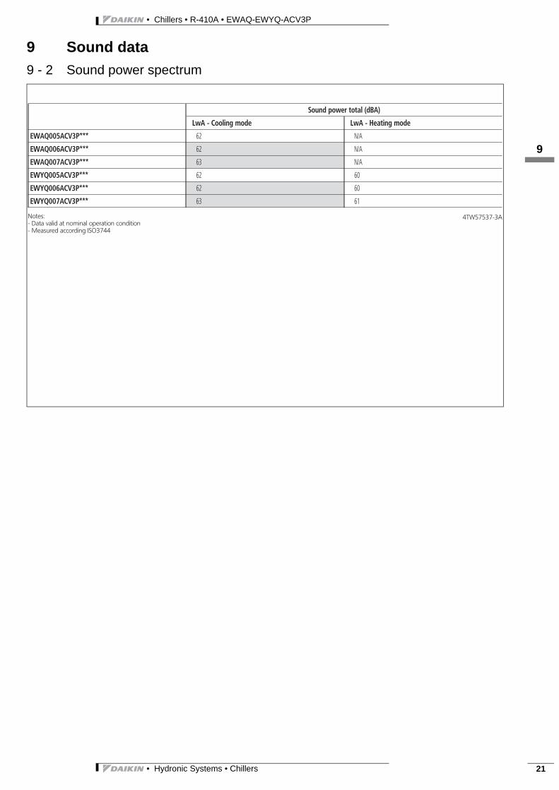
9 Sound data9 - 2 Sound power spectrum
Sound power total (dBA)
LwA - Cooling mode LwA - Heating mode
EWAQ005ACV3P*** 62 N/A
EWAQ006ACV3P*** 62 N/A
EWAQ007ACV3P*** 63 N/A
EWYQ005ACV3P*** 62 60
EWYQ006ACV3P*** 62 60
EWYQ007ACV3P*** 63 61
4TW57537-3ANotes:- Data valid at nominal operation condition- Measured according ISO3744
• Chillers • R-410A • EWAQ-EWYQ-ACV3P
110
• Hydronic Systems • Chillers22
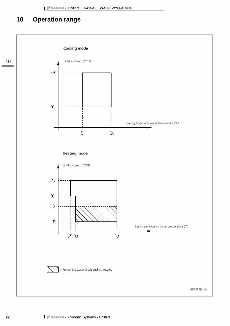
10 Operation range
4TW57533-1A
Cooling mode
Outdoor temp. (°CDB)
Leaving evaporator water temperature (°C)
Leaving evaporator water temperature (°C)
Heating mode
Outdoor temp. (°CDB)
: Protect the water circuit against freezing

3
111
• Hydronic Systems • Chillers 23
• Chillers • R-410A • EWAQ-EWYQ-ACV3P
11 Hydraulic performance11 - 1 Static pressure drop unit
4TW56749-2
ESP
[mH
2O]
Warning: Selecting a flow outside the curves cancause damage to or malfunction of the unit. See alsominimum and maximum allowed water flowrate inthe technical specifications.
ESP = f (Flow)
Flow (l/min)
I: low speed setting pumpII: medium speed setting pumpIII: high speed setting pump
ESP: External static pressureFlow: waterflow trough the unit

Air-cooled
EWAQ-ACV3P
EWYQ-ACV3P
EEDEN09- 401
EED
EN09
-401
- 12
/200
8Pr
inte
d in
Bel
gium
by
Goe
kint
Gra
phic
sCo
pyrig
ht ©
Dai
kin
Naamloze Vennootschap
Zandvoordestraat 300
B-8400 Ostend, Belgium
www.daikin.eu
BTW: BE 0412 120 336
RPR Oostende
ISO14001 assures an effective environmental management system in order to help protect human health and the environment from potential impact of our activities, products and services and to assist in maintaining and improving the quality of the environment.
Daikin Europe N.V. is approved by LRQA for its Quality Management System in accordance with the ISO9001 standard. ISO9001 pertains to quality assurance regarding design, development, manufacturing as well as to services related to the product.
Daikin units comply with the European regulations that guarantee the safety of the product.
Daikin Europe N.V. participates in the Eurovent Certification Programme for Air Conditioners (AC), Liquid Chilling Packages (LCP) and Fan Coil units (FC); the certified data of certified models are listed in the Eurovent Directory.
Daikin’s unique position as a man-ufacturer of air conditioning equip-ment, compressors and refrige-rants has led to its close involve-ment in environmental issues. Forseveral years Daikin has had the in-tention to become a leader in theprovision of products that havelimited impact on the environ-ment. This challenge demands theeco design and development of awide range of products and an en-ergy management system, result-ing in energy conservation and areduction of waste.
“The present publication is drawn up by way of information only anddoes not constitute an offer binding upon Daikin Europe N.V.. DaikinEurope N.V. has compiled the content of this publication to the bestof its knowledge. No express or implied warranty is given for thecompleteness, accuracy, reliability or fitness for particular purpose ofits content and the products and services presented therein. Specifi-cations are subject to change without prior notice. Daikin Europe N.V.explicitly rejects any liability for any direct or indirect damage, In thebroadest sense, arising from or related to the use and/or interpreta-tion of this publication. All content is copyrighted by Daikin EuropeN.V..”


