Page 1
NASA-CR-195685
AIRCRAFT WING STRUCTURE DETAIL DESIGN
421S93ADP02-2
April 14, 1993
AE421104/Team 2
Garrett L. Sager
Ron Roberts
Bob Mallon
Mohamed Alameri
Bill Steinbach
Submitted to:
Professor C. N. Eastlake
(NASA-CR-195485) AIRCRAFT WING
STRUCTURE DETAIL DESIGN
(Embry-RiddJe Aeronautical Univ.)
36 p
N94-24498
Unclas
G3/05 0204232
https://ntrs.nasa.gov/search.jsp?R=19940020025 2018-05-22T20:15:50+00:00Z
Page 2
i. Project Summary
The provisions of this project call for the design of the
structure of the wing and carry-through struct_c for the Viper
primary trainer, which is to be certified as a utility ca_go_
trainer under FAR part 23.
The specific items to be designed in this statement of work
were l) Front Spar, 2) Rear Spar, 3) Aileron Structure, 4) Wlng
Skin, and 5) Fuselage Carry-through Structure.
In the design of these parts, provisions for the fuel system,
electrical system, and control routing were required. Also, the
total weight of the entire wing planform could not exceed 216 Ibs.
Since this aircraft is to be used as a primary trainer, and
the SOW requires a useful life of 107 cycles, it was decided that
all of the principle stresses in the structural members would be
kept below i0 ksi. The only drawback to this approach is a weight
penalty.
1
Page 3
Part
Name
Front Spar
cap
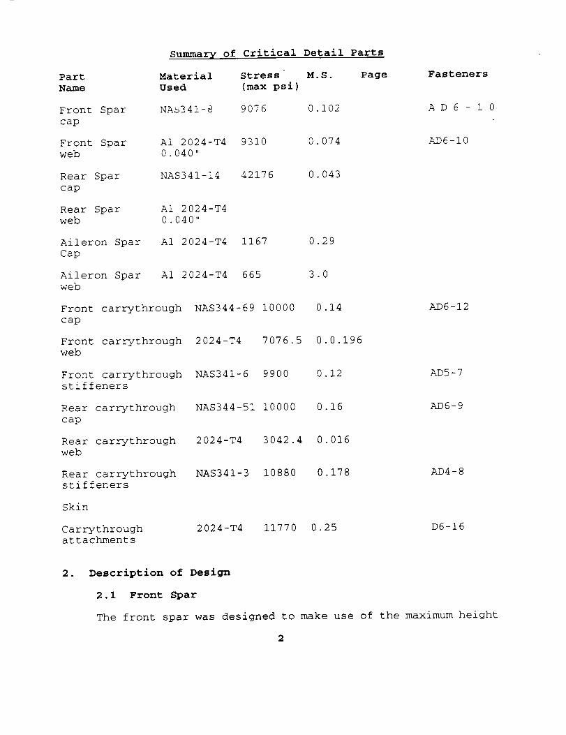
Summary of Critical Detail Parts
Material Stress M.S. Page
Used (max psi)
NAS341-8 9076 0.102
Fasteners
AD 6 - 1 0
Front Spar A1 2024-T4 9310 0.074 AD6-10
web 0.040"
Rear Spar NAS341-14 42176 0.043
cap
Rear Spar A1 2024-T4
web 0.040"
Aileron Spar A1 2024-T4 1167 0.29
Cap
Aileron Spar A1 2024-T4 665 3.0
web
Front carrythrough
cap
Front carrythrough
web
Front carrythrough
stiffeners
Rear carrythrough
cap
Rear carrythrough
web
Rear carrythrough
stiffeners
NAS344-69 i0000 0 14
2024-T4 7076.5 0 0.196
NAS341-6 9900 0 12
NAS344-51 i0000 0 16
2024-T4 3042.4 0 016
NAS341-3 10880 0 178
AD6-12
Skin
Carrythroughattachments
ADS-7
AD6-9
AD4-8
2024-T4 11770 0.25 D6-16
• Description of Design
2.1 Front Spar
The front spar was designed to make use of the maximum height
2
Page 4
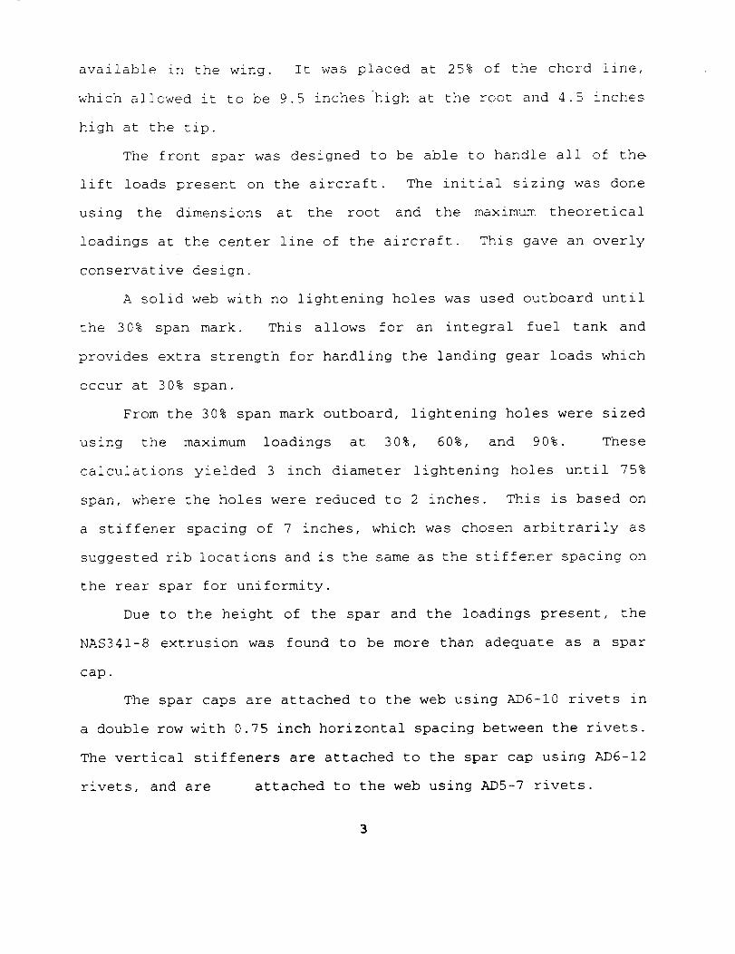
available in the wing. It was placed at 25% of the chord line,
which allowed it to be 9.5 inches _high at the root and 4.5 inches
high at the tip.
The front spar was designed to be able to handle all of the
lift loads present on the aircraft. The initial sizing was done
using the dimensions at the root and the maximum theoretical
loadings at the center line of the aircraft. This gave an overly
conservative design.
A solid web with no lightening holes was used outboard until
the 30% span mark. This allows for an integral fuel tank and
provides extra strength for handling the landing gear loads which
occur at 30% span.
From the 30% span mark outboard, lightening holes were sized
using the maximum loadings at 30%, 60%, and 90%. These
calculations yielded 3 inch diameter lightening holes until 75%
span, where the holes were reduced to 2 inches. This is based on
a stiffener spacing of 7 inches, which was chosen arbitrarily as
suggested rib locations and is the same as the stiffener spacing on
the rear spar for uniformity.
Due to the height of the spar and the loadings present, the
NAS341-8 extrusion was found to be more than adequate as a spar
cap.
The spar caps are attached to the web using AD6-10 rivets in
a double row with 0.75 inch horizontal spacing between the rivets.
The vertical stiffeners are attached to the spar cap using AD6-12
rivets, and are attached to the web using ADS-7 rivets.
Page 5
2.2 Rear Spar
The rear spar was designed s_milarly to the front spar. It
was placed at the 75% chord point to allow the flap and aileron
loads to be transfered directly to it and to provide the largest
moment armpossible between it and the front spar.
The first bay, outboard to 30% span, was kept solid for the
same reasons as the front spar, except for access holes for the
flap linkage.
This rear spar had to be designed to carry part of the lift
loads, as well as the shear, bending, and torsional loads induced
by aileron and flap deflection.
Since the height of the rear spar is smaller than that of the
front spar, larger spar caps were needed to provide the required
moment of inertia. In this case, NAS341-14 extrusions were chosen
as the spar caps, attached to the web using MS20430Db rivets
spaced 0.8 inches apart, with a total of 400 rivets.
As with the front spar, stiffeners were placed every 7 inches,
and the lightening holes were sized to be 1.5 inches in diameter
based on this and the 0.040 inch web thickness.
2.3 Carrythrough Structure
The carrythrough structure was designed as a continuation of
the front and rear spars. The carrythrough structure had to be
designed to carry twice as much loading as the front and rear spar.
The carrythrough structure was designed similarly to both the front
and rear spars. The structures maintained the same height as each
of the spars but were o[ different web thickness and stiffener
4
Page 6
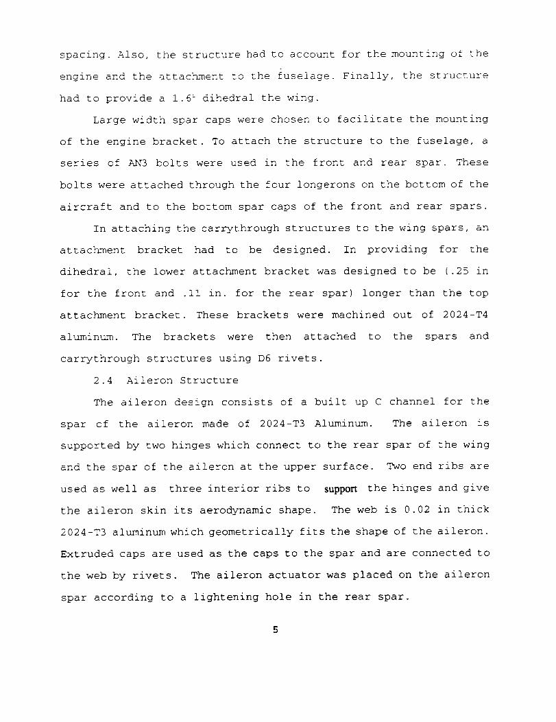
spacing. Also, the structure had to account for the mounting of the
engine and the attachment to the fuselage. Finally, the structure
had to provide a 1.6 _ dihedral the wing.
Large width spar caps were chosen to facilitate the mounting
of the engine bracket. To attach the structure to the fuselage, a
series of AN3 bolts were used in the front and rear spar. These
bolts were attached through the four longerons on the bottom of the
aircraft and to the bottom spar caps of the front and rear spars.
In attaching the carrythrough structures to the wing spars, an
attachment bracket had to be designed. In providing for the
dihedral, the lower attachment bracket was designed to be (.25 in
for the front and .ii in. for the rear spar) longer than the top
attachment bracket. These brackets were machined out of 2024-T4
aluminum. The brackets were then attached to the spars and
carrythrough structures using D6 rivets.
2.4 Aileron Structure
The aileron design consists of a built up C channel for the
spar of the aileron made of 2024-T3 Aluminum. The aileron is
supported by two hinges which connect to the rear spar of the wing
and the spar of the aileron at the upper surface. Two end ribs are
used as well as three interior ribs to support the hinges and give
the aileron skin its aerodynamic shape. The web is 0.02 in thick
2024-T3 aluminum which geometrically fits the shape of the aileron.
Extruded caps are used as the caps to the spar and are connected to
the web by rivets. The aileron actuator was placed on the aileron
spar according to a lightening hole in the rear spar.
Page 7
2.5 Wing Skin
3. Loads and Loadings
The external loadings on the wing structure were determined
using the stripwise estimation method outlined in Chapter 3 of the
Niu text.
This method yielded a non-dimensional lift distribution over
half of the planform, which was multiplied by n*(W/2) to determine
the actual loads present.
A curve was faired through the points determined by this
estimation, and the lift force at 10% span increments was found
from this graph.
This lift distribution is shown in the accompanying graph.
From this, the maximum lift force at the centerline of the
aircraft, due to the lift on each half-span, was found to be 3538
ibs., and the maximum bending moment was determined to be 1485 ft.-
Ibs.
At high angles of attack, these loads were assumed to act at
25% of the wing chord, and at low angles of attack these forces
were assumed to move to the 33% chord point.
The front spar was assumed to carry this entire load at high
alphas, and 2/3 of this load at low alphas.
At high angles of attack, the rear spar carries none of the
primary lift loads, and carries 1/3 of these loads at low angles of
attack.
The rear spar also carries the lift loads from the flaps and
ailerons, which are transmitted to it at their respective hinge
6
Page 8
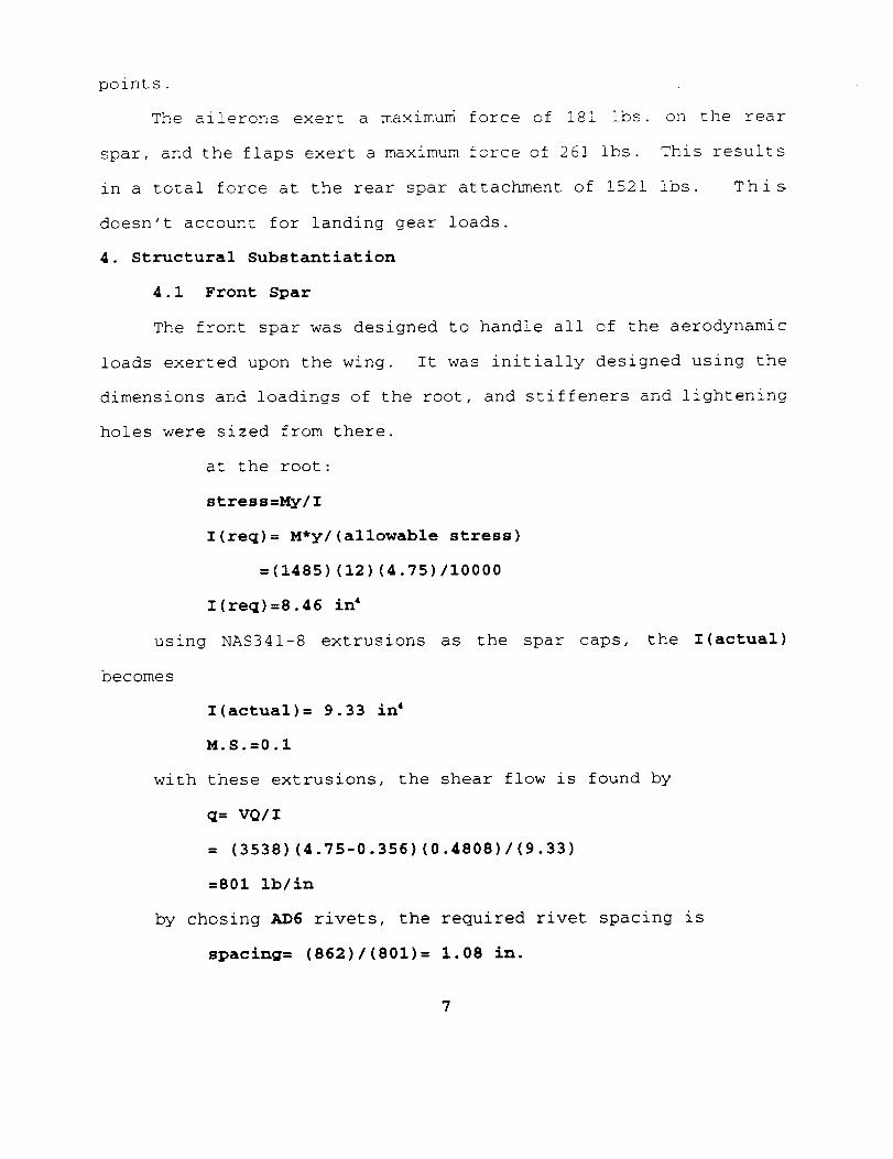
points.
The ailerons exert a maximum force of 181 ibs. on the rear
spar, and the flaps exert a maximum force of 261 ibs. This results
in a total force at the rear spar attachment of 1521 ibs. This
doesn't account for landing gear loads.
4. Structural Substantiation
4.1 Front Spar
The front spar was designed to handle all of the aerodynamic
loads exerted upon the wing. It was initially designed using the
dimensions and loadings of the root, and stiffeners and lightening
holes were sized from there.
at the root:
stress=My/I
I(req)= M*y/(allowable stress)
=(1485)(12)(4.75)/10000
I(req)=8.46 i_
using NAS341-8 extrusions as the spar caps, the i(actual)
becomes
I(actual)= 9.33 i_
M.S.=0.1
with these extrusions, the shear flow is found by
q= VQ/I
= (3538)(4.75-0.356)(0.4808)/(9.33)
=801 Ib/in
by chosing AD6 rivets, the required rivet spacing is
spacing= (862)/(801)= 1.08 in.
7
Page 9
using a rivet spacing of 0.75 in yields
M.S.= (1.08)/(0.75)-I =0.44
The shear flow in the web is given by
q=V/h = (3538)/(9.5)= 372 ib/in
t= (372)/(10000) = 0.0372
t= 0.040
Similar calculations were performed at 30% span and at 60%
span to ensure the feasibility of these initial choices.
At 30%:
V=2177 lb.
I(req)= 3.026 in 4
I(actual)= 7.74 in 4
q(cap)=492.7 Ib/in
q(web)= 272 1b/in
M=630.5 ft.-lb.
At 60%:
V=984 Ib
I(req)= 0.636 in 4
i(actual)=4.07 in 4
q(cap)=336.5 Ib/in
q(web)= 151 ib/in
M=161.6 ft-lb
Lightening holes and stiffeners were used from 30% span
outboard. Stiffeners were placed arbitrarily at 7 in. intervals.
The allowable hole size using 0.040 in. thick sheet for the web
worked out to be 4 in. However, due to geometric constraints, this
Page 10
was reduced to 3 in., with a further reduction to 2 in. at spar
station 122.
Composite analysis on web
N_= 3538 ib
GT=600000 ib/in
ET= 1.5"106 ib/in
Using data from p. 519 of the Niu text, the size of the
web is dependant upon the stiffness requirements, which yields
24 plies, 0.005 in thick each, 0.12 in. total thickness
4.2 Rear Spar
f=My/I = (12834.2)(2)/(0.1443) = 42176 psi
M.S.= (44000)/(42176)-I = 0.043
This moment of inertia was obtained using NAS341-14
extrusions.
At 40% outboard, the loads were rechecked and the spar
cap changed to a NAS341-13.
M=5208 in.-ib. I=0.1248 in. 4
M.S.= 0.27
At 60% outboard, the spar caps were changed again, this
time to NAS341-7.
M=1939.2 in. -ib
M.S.= 0.2
Using D5 rivets, the rivet spacing is
(755) / (943)=0.8
M.S. = (943)/(681) = 0.39
This requires 400 rivets.
I=0.0348 in 4
9
Page 11
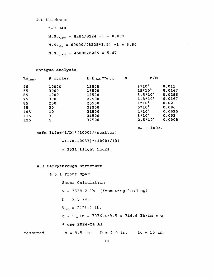
Web thickness
t=0.040
M.S..now = 8284/8224 -i = 0.007
M.S.ul _ = 60000/(8225"1.5) -I = 3.86
M.S.y_.id = 45000/8225 = 5.47
Fatigue analysis
# cycles f=f1_t*n1±m±_ N
45
55
65
75
85
95
105
115
125
n/N
I0000 13500 9"10'
3000 16500 18"105
I000 19500 3.5"104
300 22500 1.8"104
200 25500 1"104
30 28500 5"10'
I0 31500 4"10'
3 34500 3"10'
2 37500 2.5"10'
safe life=(1/D)*(1000)/(scattor)
=(1/0.10037)*(1000)/(3)
= 3321 flight hours.
D= 0.10037
0.011
0.0167
0.0286
0.0167
0.02
0.006
0.0025
0.001
0.0008
*assumed
4.3 Carrythrough Structure
4.3.1 Front Spar
Shear Calculation
V = 3538.2 ib (from wing loading)
h = 9.5 in.
V_o_ = 7076.4 lb.
q = V_o_/h = 7076.4/9.5 = 744.9 Ib/in = q
* use 2024-T4 A1
h = 9.5 in. D = 4.0 in.
I0
b_ = i0 in.
Page 12
Table 4.1.1
t b_/t F< K: F_ f_
.05 200 6800 1.38 9384 14898
.063 159 8100 1.19 9639 11824
.071 141 9000 1.08 9720 10492
.08 125 9500 0.98 9310 9311
.09 iii ii000 0.9 9900 8278
From Niu text pg. 169)
Fig. 4.1.1
t = 0.09 in.
M.S. = 9900/8278 - 1 = 0.196 = M.S.
Stiffener Area
These equations are taken fron the Niu text ex.#2
pg. 169 & 170.
Ao = b=(t) {.385 - 0.08(b_/h) _]
Ac, = -
* This equation provided a negative area.
A_ let to = t = .09
bu1/t _ = 9 bo2/t o : 12
b_ = 9(.09) = 0.81
bo2 = 12(.09) = 1.08
Ao:_q = (.81+1.08) (.09) = 0.1701 = Aor.q
Inertia of Stiffeners
ii
Page 13
i<_= F_ t b_ h: / 10t(h-D)
= 9900(.09) (I0) (9.5):/i0_(9.5 - 4.0)
I_ = 0.00139 in. _
This is the minimum moment of inertia required for
the stiffeners.
Actual Io
: t o b02 _ (4b0: + b_)/!2(b_ + b_i)
Io_c _ = 0.0216 in. 4 > minimum inertia.
* Use stiffener to fit required moment of inertia
NAS341-6
Web-to-Flange Riveting Strength
qr = 1.25 F_ t (h/h-d)
= 1.25(9900) (.09) (9.5/9.5-4.0)
= 1923.8 ib/in = qr
* use AD6 rivets, double row, spaced 0.8 in.
q:_111 = 862(2)/0.8 = 2155 Ib/in
M.S. = 2155/1923.8 - 1 = 0.1201 = M.S.
Web-to-Stiffener Rivet Strength
P_ = .0024 Ao F o bs/t (h/h-D)
P_t = .0024(.2003) (9900) (i0)(9.5/5.5)/.09
P,_ = 940.7 Ib
* use AD5 rivets .75in. spacing
P_ = 596(2) = 1192 ib
M.S. = 1192/940.7 - 1 = 0.267 = M.S.
Equivalent-Weight Thickness (web)
teq = t(l - 0.785 D2/b_h + Ao/b_t)
12
Page 14
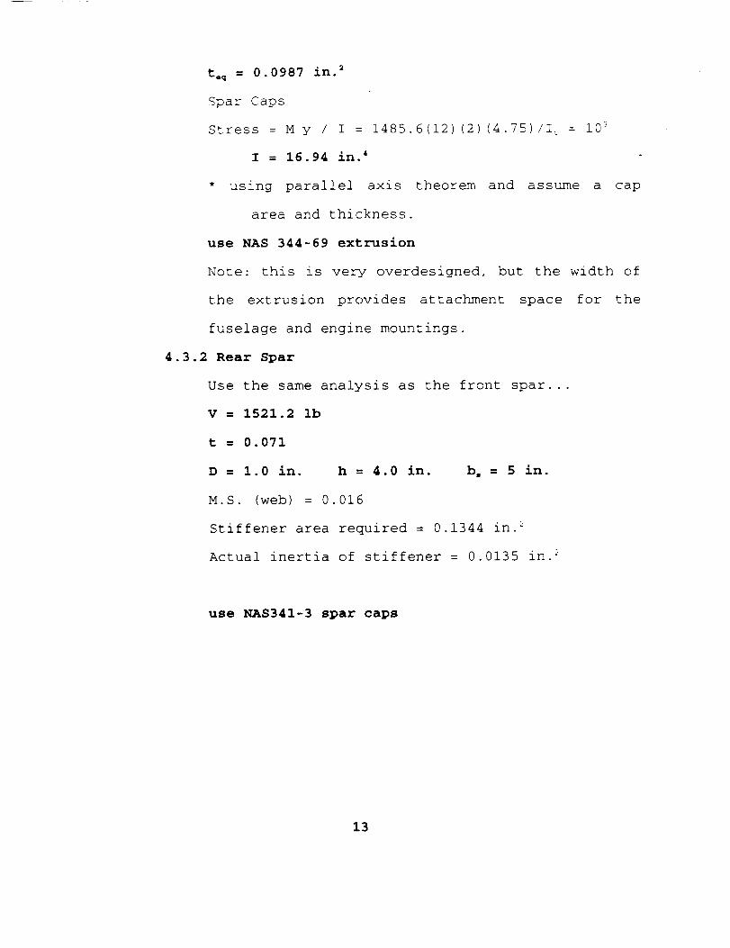
t.q = 0.0987 in.2
Spar Caps
Stress = M y / I = 1485.6(12)(2)(4.75)/I_ : i0 _
I = 16.94 in. 4
* using parallel axis theorem and assume a cap
area and thickness.
use NAS 344-69 extrusion
Note: this is very overdesigned, but the width of
the extrusion provides attachment space for the
fuselage and engine mountings.
4.3.2 Rear Spar
Use the same analysis as the front spar...
V = 1521.2 ib
t = 0.071
D = 1.0 in. h = 4.0 in. b, = 5 in.
M.S. (web) = 0.016
Stiffener area required = 0.1344 in. _
Actual inertia of stiffener = 0.0135 in. 2
use NAS341-3 spar caps
13
Page 15
!
....t
, 7
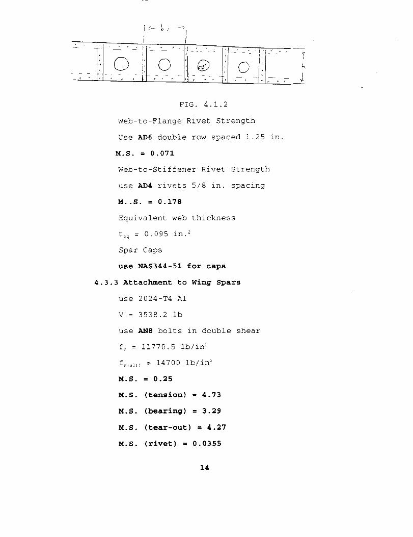
FIG. 4.1.2
Web-to-Flange Rivet Strength
Use AD6 double row spaced 1.25 in.
M.S. = 0.071
Web-to-Stiffener Rivet Strength
use AD4 rivets 5/8 in. spacing
M..S. = 0.178
Equivalent web thickness
t_! = 0.095 in. 2
Spar Caps
use NAS344-51 for caps
4.3.3 Attachment to Wing Spars
use 2024-T4 A1
V = 3538.2 ib
use AN8 bolts in double shear
f_ = 11770.5 ib/in 2
f_c_,_tl = 14700 ib/in _
M.S. = 0.25
M.S. (tension) = 4.73
M.S. (bearing) = 3.29
M.S. (tear-out) = 4.27
M.S. (rivet) = 0.0355
14
Page 16
Note: bottom attachment must be .25 longer on
the front spar and .ii longer on the rear spar.
7/,3/
2 ÷ +
4.3.4 Composite Analysis
"7
This is a copy of example of #2 pg. 519 in the Niu
text.
Nx = 0
Ny : 0
Nxy = 744.9
GT = 600000 ib/in
ET = 1.5 X l0 t ib/in
Shear Requirement
# of +/- 45 ° plies
Nxy/(tF_) : 744.91b/in/(.005x38000)
4.3.5 Aileron Structure
Web
shear fs = V/ ht
V = 90.5 ib
h = 3.5 in
f = 34000 psi
t = 0.00076 inch
15
Page 17
buckling
k,. = 4.0
v_ : 0.3
E = i0.6E6
f_i_ = 665.3 ib
Use thickness skin : 0.02 in
= (3.1415): k_ E/ 12(1- v_) (t/b)_
from Bruhn
Caps
compression
Skin
torque
f< = My/I
M = 778 inlb x 1.5
y = 2.4 in
f= = 38000 ib
I = 0.0737
fs = T/2At
T = 4675.0 inlb
A = 21 in 2
f_ = 39000 ib
t = 0.00286
use Cap with I = 0.0776
use 0.02 in thick skin
4.3.6 Composite Investigation
Composite investigation for the aileron skin
Fy = 13110 ib
Fx = 0.0 ib
Fxy = 5565 ib
for 45_' plies Nxy = n4s x t x F_2
16
Page 18
5565 ib/ (0.005 (38000) = 29.8 plies
for 90_ plies Ny - F:_:_ x t_ / t x F_. = n _'c_
13110 - (15000) (0.005)(30) / (0.005) (98000) = 22.16 plies
for 0 ° plies Fx : 0 therefore use 10% of total number for
stability
o
45 ° plies = 30 plies
90 ° plies = 23 plies
0 ° plies = 5 plies
Manufacturing and Maintenance
When assembling this wing, the wing structure alone should be
assembled first, including
should be attached to the
fuselage.
the skin and ailerons, and then it
carrythrough structure within the
The front and rear spars are constructed of thin aluminum
sheet with extrusions riveted to them. It is recomended that the
web be cut to dimension first, including cutting lightening holes,
and then the spar caps and stiffeners riveted to the web.
The spar assemblies can be covered with skin and the ailerons
then attached to the rear spar.
Manufacturing of the ailerons begins with the making of the
spar which is a built up C channel. A 0.02 inch thick sheet of
2024-T3 aluminum is cut to the proper dimensions to serve as the
web of the spar. The extruded L sections used for the
caps are then riveted to the sheet according to the design
17
Page 19
drawings. Five ribs, which can be hydropressed, are connected
perpendicular to the spar to givethe skin of the aileron its
airfoil shape. For the skin two sheets of 2024-T3 aluminum is
again used at 0.02 inches thick for both the upper and lower half-
of the skin. Two hinges are used at 25 and 75% span of the aileron
to connect the aileron itself to the rear spar of the wing.
No access panels are incorporated into the aileron design
because interior parts do not need to be inspected on a regular
basis.
This manufacturing process seems to be the most reasonable.
A built up C channel is cheaper to make than an extruded C section
because of the changing height of the web. From the composites
calculation a composite structure could work for the skin but it
was felt that this would add to much cost to the aircraft and also
a primary trainer would be subjective to frequent inspections and
unusual loading. With these considerations aluminum pieced
together would be more logical.
From this, all that remains is bolting the wing structure to
the carrythrough.
6. Cost Analysis
. Weight summary
Front spar- 221bs.
Rear Spar-
Carrythrough- 16.37 Ibs
18
Page 20
Aileron-
caps 2 at 2.8 ibs each
web 1 at .1505 ibs
ribs 5 at 0.0541
skin 2 at 1.86
rivets 1 lb
5.60 ibs
0.31 lbs
0.27 Ibs
3.72 ibs
1.00 ibs
total aileron weight half span
Skin-
Total half span weight =
Total planform weight=
10.90 Ibs
8. Conclusions
Due to the time constraints, complete optimization analysis
was not possible. This resulted in a structure that would be
slightly over the minimum possible weight to carry the loadings
present.
Also, many of the detail parts were chosen based on
conservative assumptions, since this aircraft will be used as a
trainer and is destined for abuse unknown to other types of
aircraft. Again, this results in a conservative design which
satisfies the FAR "fail-safe" requirement.
19
Page 21
v" ....
o I,.,.--+-.I
.,.l..,Jl
X
o g,,--I
+
l
Page 22
0
Jl, _ \
t
: ,=-
..° .r _ /_
L.__._ \ /
_ _____
N, / i
, /L.t-I \'J ;
_.E_. __-J L........l ..- l ..l............. I.........Jl ....J c_
I I I
Page 23
AT]_t-_ _]l_ S'l'[:[l-__- DL:"I'_-[I. DESIg
Report Additions: Wing Skin
421S93ADP02-2
4-19-93
AE421/04/TEAM #2
LEAD ENGINEER:
Garrett Sager
TEAM MEMBERS:
Bob Mallon
Mohamed Alameri
Bill Steinbach
Ronald Roberts
SUBMITTED TO:
Professor C.N. Eastlake
04/16/93
Page 24
Table of Contents
Wing Skin Report Additions
2. Design Description ..................... 1
2.5 Wing Skin ........................ 1
4. Structural Substatantiation ............ 2
4.5 Wing Skin ........................ 2
4.5.1 Composite Analysis ............. 3
5. Manufacturing and Maintenance .......... 5
5.5 Wing Skin ........................ 5
7. Weight Summary ......................... 3
8. Wing Skin Conclusions ................... 6
9. Appendices ............................. 7
A. Environmental Conditions .......... 7
B. A-size Wing Skin Drawing .......... 9
C. Wing Torque vs. Span Graph ........ I0
D. FORTRAN program for wing torque ... II
Page 25
2.5 Wing Skin
The wing skin caries the torque load created by the i) lift
distribution 2) moment about the mean aerodynamic chord and 3) flap
and aileron hinge forces. The center of torque was assumed to be at
40% of the chord by Niu (pg.85) suggestion. The torque loading
varies parabollicaly from 0.0 at the wing tip to a maximum value at
the root, the hinge reactions from the flaps and ailerons were
modeled as point loads [see Appendix: graph 3).
The shear flow calculations indicated that a very thin
aluminum skin would provide the needed shear flow path. However a
0.02in. skin was selected to avoid wrinkling, meet environmental
condition requirements, and aid in easy manufacturing and assembly.
Page 26
4.5 Wing Skin
The wing skin provides the reaction for the wing torque
created by the aerodynamic loads which acts about the 40% chord.
The shear flow at l)the root 2) the midspan and 3) slightly in-
board of the tip are the critical positions for determining skin
thickness and rivet spacing.
In-board of TiD:
q= T/2A (568 Ibs.)/2,(41.6) = 6.83 ibs./in.
Rivets=: MS20470AD-3 From MiI-HB5 f, = 2171bs.
Recommended Spacing: 2171b/6.831bs/in = 31 in.
This large calculated rivet spacing is due tothe reduction of torsion to zero at the tip.
Selected Spacing: 4.0 in.
At midspan fSkin over-lap_:
T = 10,260 in-lbs. Area = 108 in 2
Same rivet and math as above,
q = 47.5 Ibs/in. Calculated spacing- 4.6in.
Selected spacing - 2.5 in.
Spacing M.S. - 2.5/4.6 - I = 0.45
At Wina Root:
T - 28,061 in-lbs. Area - 208 in 2
Same rivet and math as above,
q - 67.5 ibs/in. Calculated spacing- 3.2in.
Selected spacing - 2.0 in.
Spacing M.S. z 2.0/3.2 - I = 0.38
Page 27
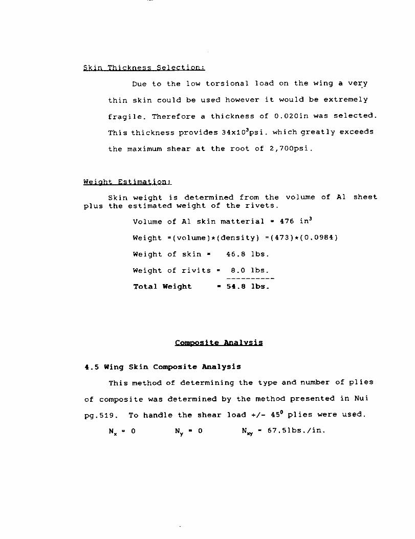
Skin Thickness Selection:
Due to the low torsional load on the wing a very
thin skin could be used however it would be extremely
fragile. Therefore a thickness of 0.020in was selected.
This thickness provides 34x103psi. which greatly exceeds
the maximum shear at the root of 2,700psi.
Weight Estimation:
Skin weight is determined from the volume of A1
plus the estimated weight of the rivets.
Volume of A1 skin matterial = 476 in 3
Weight =(volume),(density) =(473),(0.0984)
Weight of skin = 46.8 Ibs.
Weight of rivits = 8.0 Ibs.
Total Weight - 54.8 Ibs.
sheet
Commosite Analysis
4.5 Wing Skin Composite Analysis
This method of determining the type and number of plies
of composite was determined by the method presented in Nui
pg.519. To handle the shear load +/- 450 plies were used.
N x _ 0 Ny - 0 N_ - 67.51bs./in.
Page 28
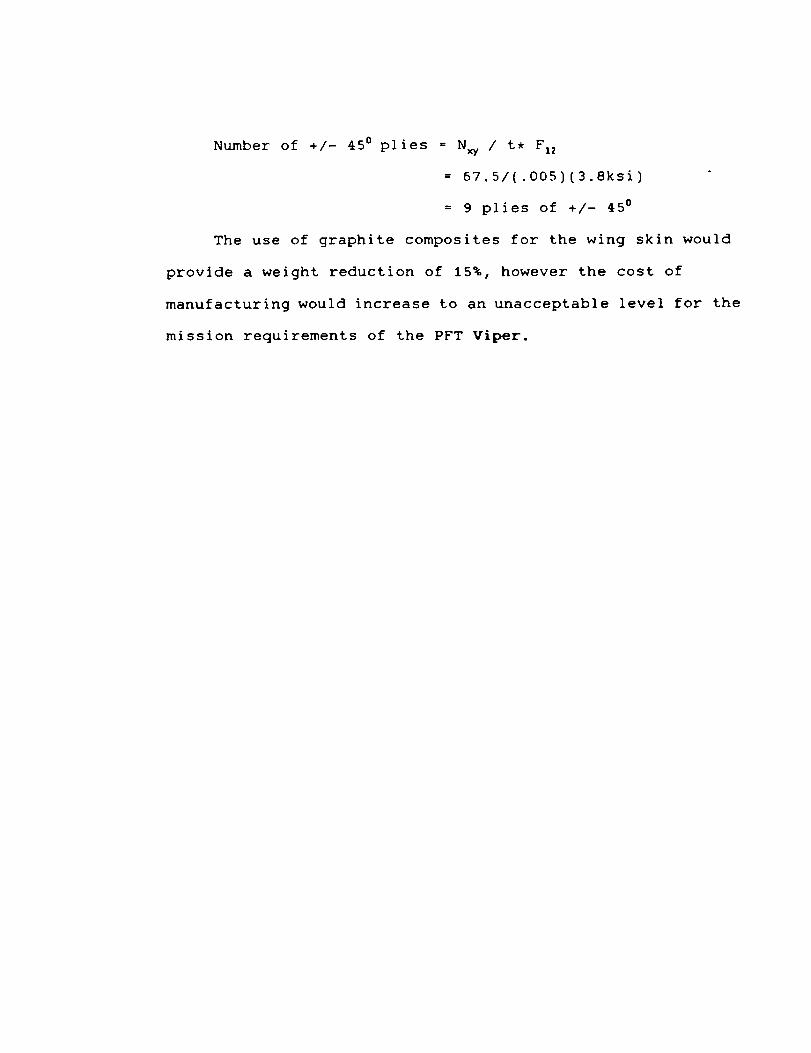
Number of +/- 45° plies = N_ / t, F,2
= 67.5/(.005)(3.8ksi)
= 9 plies of +/- 45 °
The use of graphite composites for the wing skin would
provide a weight reduction of 15%, however the cost of
manufacturing would increase to an unacceptable level for the
mission requirements of the PFT Viper.
Page 29
5.5 Manufacturing and Maintenance of Wing Skin
The wing skin consist of five separate panels that will be
riveted to the spars, ribs and each other. The four panels the
cover the upper and lower planform will be cut from 4'x8' A1
sheets, the outboard panel will be installed first so that the
inboard panel over-laps the out-board panel by about 3.0inches. The
final panel will be a 3'x16' sheet that will be hand formed around
the leading edge. To avoid flow spoilage no rivets will be used on
the nose of the airfoil and as few as possible in the region near
the leading edge, approximately 2in. away.
The four wing skin panel will be riveted to the front and rear
spar, the ribs spaced 7.0in. apart and at the over lap point. The
rivet spacing determined near the root (high stress area) should be
2.0 in., near the midspan (panel over-lap) 2.5 in., and near the
wing tip 4.0 inches. The skin will be fastened to the ribs by 425
MS2047AD-3 rivets and to the front and rear spar by 218 rivets; the
rivet edge distance will be 0.25 in. Note the number of parts
listed above is for a semi-span, multiply by 2 for the total number
of parts for the entire wing.
The wing skin will be painted to protect the material and meet
the environmental requirements set in the Statement of Work #2. ,
See Appendix for Environmental Conditions.
Page 30
8.1 Wing Skin Conclusion
The low wing torque created by the i) lift distribution 2)
moment about the mean aerodynamic chord and 3) flap and aileron
hinge forces permits a very thin skin which is extremely difficult
to work with, so a durable and standard size A1 sheets were used.
The protective coating (paint) on the skin will meet the
environmental requirements set in the Statement of Work #2.
Unfortunately the target wing weight of 216 Ibs. was not
achieved. Based on the findings in this report the wing designed by
Team #2 is a suitably strong, rigid and light wing structure that
is well suited for the Primary Flight Trainer Viper.
Page 31
Appendix A
Envi r¢>_nta ]_ CQn¢_[.i. t J.¢>ns
I. Temperature
All modes of operation and storage
temperatures from -40_ to +122°F.
shall not be degraded for
2. Atmospheric Pressure
Operation to I0,000 feet (ICAO Std.) shall be possible.
3. Sand and Dust
External surfaces, mechanisms and associated items shall endure up
to 150 microns in size and combinations of sand and dust in
concentrations up to 0.041 grams per cubic foot without
degradation.
• . Rain
All external surfaces, mechanisms and associated items shall endure
and seal against water intrusion from rainfall at a rate up to 4.0
inches/hour with wind velocities up to 50 mph. Any cavities that
could hold water shall be provided with a drain.
5. Humidity
External surfaces, mechanisms and associated items shall endure up
to I00 percent relative humidity at +95_ without degradation.
Page 32
6. Ice
All external surface, mechanisms and associated items shall endure
ice at temperatures to -40_ and remain operational.
7. Snow
All horizontal external surface, mechanisms and associated items
shall endure accumulations for depths up to 8.0 inches of wet snow.
8. Salt/Fog Atmosphere
All external surface, mechanisms and associated items shall
withstand prolonged exposure to salt/fog atmosphere as encountered
in coastal areas without degradation in performance, there shall be
no binding of moving parts nor corrosion that obstructs operation.
9. Wind and Gust
Wind of 50 mph with gust in accordance with FAR23 shall not degrade
operation. Ground tie downs shall withstand loads associated with
a wind of 120 mph from any lateral direction and from
elevation/depression angles of up to I0 degrees.
10. Shock and Vibration
The airplane structure designed shall withstand shock vibration
loads associated with normal operation and storage in accordance
with FAR23 section 2.1
Page 33
r _
....
uJ
o-
/
..2
d
._.L
.....2" _
i
-Z , !
c_-_
,_.!_ _ .N
iI
I
C]Cu.J
--c
_'.E: ?
o _
____] _ --
,..Of c. :_
i _ " k'-
i i -:- ._A<'4) -_ -. .._
....................................... .... j I - -
Page 34
b._._
t2
_: I C."
L;
Page 35
'tl
28O
788
4_0
458
50O
r)i ooraPl "_C'i"O_('
d ir._ens Jor, [)c,s f in'_.,_, . _.z .,....._,........,,._:=.__.s :: ,;J 7'_;..5i,_. ,.i....I). r,_..'r 11 '
do 10D n=.I.12Wi"i_e (6. *) . e_'t t _ i" S[., a /; O _.:_-., __] C, :_ _ ..'0 _cal sheaf foi'ce _
read (5.*).r..,os('n).sT_r_..... J.
C u,I_ ,_ il]Lle
do 2_0 m=l.ll
dei t'sz(r,_)=sz (r,_)-sz (r,_+i
d_w (m) =deltsz (Pi)'0.!5, (69. 36-78. 7,*::os(m>)
c an'd:inue X_ _ '%
_,c,r,=B. Bde, 400 k=l. II C,"-,e "_ : Z,
_._o3B0 l=k.ll:,Lc.r,_=r,,or.'_+dr.re ( 1 )
C C' 'r_t i "q U e
i';], ( ]_ ) :a:PiC'PI
pa..-,m=_.
t- - -J-.... li ,. i i]ue
w;"ire (6. *). 'oosition I)eit aSz d_ly
do 5_0 .i=1.!1
w,- ite (6. 458) ..pos ( .i ). de 1tsz (.i). dm',, (.i) .._iy ( .i ){c.r_at (!x.fS."_.' '.f8. o. ,.' '.f8.1.' 'flB. 2)C o'h_ i _'_u e
end
zz/.,e...
My'
OIEtGINAL PAGE IS
OF POOR QUALITY
Page 36
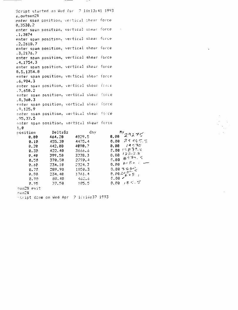
r_ .. .:Jc,ipt started on Wed Aor 7 16:13:41 1993a.outsun2X
enter soail oositior,_ vertic._,] she.-:_r" force
O. 3538.2enter soan Position. vertical shear force
• 1. 3074
enter span oosition., vertical shea force
.2.2618.7
enter span oosition, vertical shear force
.3.2176.7
enter soan oosition, vertical shear force
•4. 1754.3
enter soan oosition, ve',-tical shE,a; ,c,zue
0.5. 1354.8
enter soan oosition vertical _.,_,e_:,_....... force
•6. 984.3
e..-,ter soan oosition vertJ.c_,l _ ........ " ...._llt_'cll I L I Lt
.7. 650.2enter soan osition, vertic_,i sl_ear !orce
.8.360.3_'nter sr, an oosition, verti,:_l __,,_t,_ i':_rce
.9.125.9
er, ter s_an oosition, vertical shea_ _o,-,-e
.%,.37.5
<<nter soan oosition, vertical shear fc, rce
1.0
i::,osition DeltaSz dr.w
0.00 464.20 4829.5
0.10 455.30 4475.4
0.20 442.00 4B90.7
0.3_ 422.40 3666.6
_. 40 399.50 3.,.o8, 3
0.50 370.5_ 2790.4
_.6_ 7,_4 10 o_oa
1,-J_,6. "_. 7_ 289.90 """:" '_. 8_ 234.4_. .!7,61 ,. 4
_._r_,_ o,::.'-''40 ..,o_.' 6
sun2% exit
_un2_,
::..-.riot de.he on Wed A0r 7 Ic;io:'-7_.Irr_
•
0. _0 / _ q -4&'
O.OO z _._.; 2. g