39
Alaska Department of Transportation and Public Facilities Alaska Field Rock Classification and Structural Mapping Guide Effective October 1, 2003
Alaska Department of Transportation and Public Facilities
Alaska Field Rock Classification and Structural Mapping Guide Effective October 1, 2003

Table of Contents
Preface ............................................................................................................................. iii
1. Rock Classification................................................................................................. 1-1 1.1. Introduction ................................................................................................................................1-1 1.2. Primary Division.........................................................................................................................1-2 1.3. Igneous Rocks.............................................................................................................................1-2
1.3.1 Textural Definitions..............................................................................................1-3 1.3.2 Color Index...........................................................................................................1-4 1.3.3 Mineralogy ...........................................................................................................1-5
1.4. Sedimentary Rocks .....................................................................................................................1-6 1.4.1 Textural Terms .....................................................................................................1-6 1.4.2 Descriptive Terms.................................................................................................1-7 1.4.3 Other Features......................................................................................................1-7
1.5. Metamorphic Rocks....................................................................................................................1-8 1.5.1 Structural Terms...................................................................................................1-8 1.5.2 Complications.......................................................................................................1-9
2. Structural Characteristics of Rock........................................................................ 2-1 2.1. Introduction ................................................................................................................................2-1 2.2. Stability Analysis of Rock Masses .............................................................................................2-1 2.3. Rock Mass Classification and Description .................................................................................2-2
2.3.1 Rock Type (“A”)...................................................................................................2-5 2.3.2 Wall Rock Strength (“B”) ....................................................................................2-5 2.3.3 Weathering (“C”).................................................................................................2-5 2.3.4 Discontinuity Type (“D”).....................................................................................2-6 2.3.5 Discontinuity Orientation (“E”) ..........................................................................2-6 2.3.6 Roughness (“F”) ..................................................................................................2-6 2.3.7 Aperture (“G”) .......................................................................................................2-7 2.3.8 Infilling Type and Width (“H”) ............................................................................2-8 2.3.9 Spacing (“I”)........................................................................................................2-8 2.3.10 Persistence (“J”)..................................................................................................2-9 2.3.11 Number of Sets (“K”)...........................................................................................2-9 2.3.12 Block Size and Shape (“L”) .................................................................................2-9 2.3.13 Seepage (“M”) ...................................................................................................2-10
2.4. Rock Quality...............................................................................................................................2-10 2.5. Rockfall Hazard and Slope Management ...................................................................................2-11
3. Structural Rock Mapping Procedures................................................................... 3-1 3.1. Introduction ................................................................................................................................3-1 3.2. Critical Features Mapping ..........................................................................................................3-2 3.3. Line Mapping .............................................................................................................................3-2
Field Rock Classification i Table of Contents And Structural Mapping Guide Effective October 1, 2003

3.4. Window Mapping .......................................................................................................................3-2 3.5. Mapping Procedure.....................................................................................................................3-3
3.5.1 Review Available Information ..............................................................................3-3 3.5.2 Prepare Rock Mapping Plan ................................................................................3-3 3.5.3 Conduct Mapping According to Plan...................................................................3-4 3.5.4 Field Book/Mapping Form Entries.......................................................................3-4
Appendix A. Forms .........................................................................................................A-1
Table of Contents ii Field Rock Classification Effective October 1, 2003 and Structural Mapping Guide
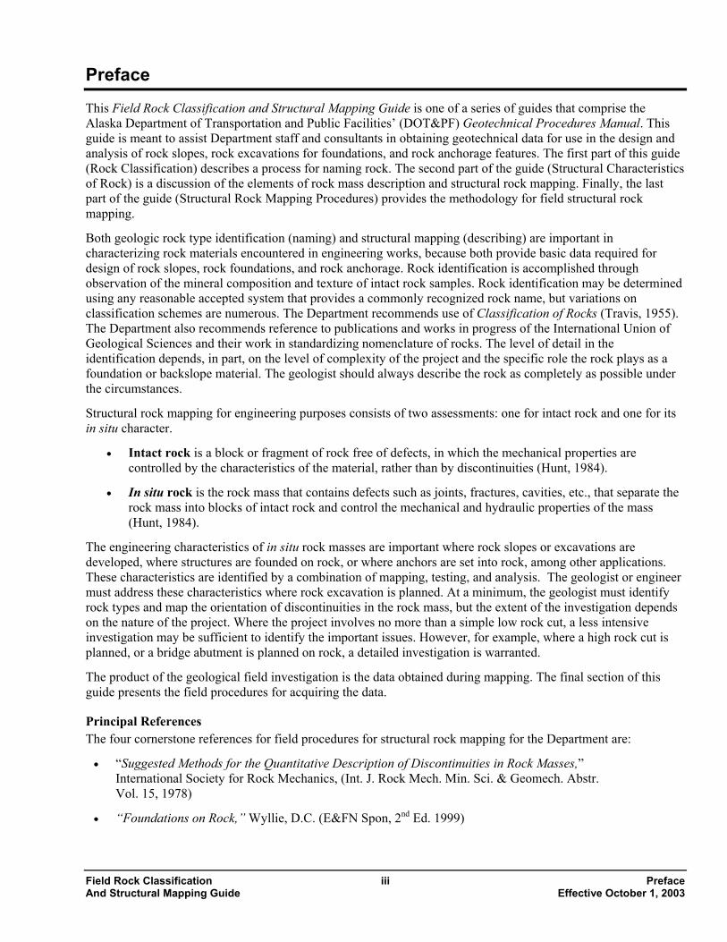
Preface This Field Rock Classification and Structural Mapping Guide is one of a series of guides that comprise the Alaska Department of Transportation and Public Facilities’ (DOT&PF) Geotechnical Procedures Manual. This guide is meant to assist Department staff and consultants in obtaining geotechnical data for use in the design and analysis of rock slopes, rock excavations for foundations, and rock anchorage features. The first part of this guide (Rock Classification) describes a process for naming rock. The second part of the guide (Structural Characteristics of Rock) is a discussion of the elements of rock mass description and structural rock mapping. Finally, the last part of the guide (Structural Rock Mapping Procedures) provides the methodology for field structural rock mapping.
Both geologic rock type identification (naming) and structural mapping (describing) are important in characterizing rock materials encountered in engineering works, because both provide basic data required for design of rock slopes, rock foundations, and rock anchorage. Rock identification is accomplished through observation of the mineral composition and texture of intact rock samples. Rock identification may be determined using any reasonable accepted system that provides a commonly recognized rock name, but variations on classification schemes are numerous. The Department recommends use of Classification of Rocks (Travis, 1955). The Department also recommends reference to publications and works in progress of the International Union of Geological Sciences and their work in standardizing nomenclature of rocks. The level of detail in the identification depends, in part, on the level of complexity of the project and the specific role the rock plays as a foundation or backslope material. The geologist should always describe the rock as completely as possible under the circumstances.
Structural rock mapping for engineering purposes consists of two assessments: one for intact rock and one for its in situ character.
• Intact rock is a block or fragment of rock free of defects, in which the mechanical properties are controlled by the characteristics of the material, rather than by discontinuities (Hunt, 1984).
• In situ rock is the rock mass that contains defects such as joints, fractures, cavities, etc., that separate the rock mass into blocks of intact rock and control the mechanical and hydraulic properties of the mass (Hunt, 1984).
The engineering characteristics of in situ rock masses are important where rock slopes or excavations are developed, where structures are founded on rock, or where anchors are set into rock, among other applications. These characteristics are identified by a combination of mapping, testing, and analysis. The geologist or engineer must address these characteristics where rock excavation is planned. At a minimum, the geologist must identify rock types and map the orientation of discontinuities in the rock mass, but the extent of the investigation depends on the nature of the project. Where the project involves no more than a simple low rock cut, a less intensive investigation may be sufficient to identify the important issues. However, for example, where a high rock cut is planned, or a bridge abutment is planned on rock, a detailed investigation is warranted.
The product of the geological field investigation is the data obtained during mapping. The final section of this guide presents the field procedures for acquiring the data.
Principal References The four cornerstone references for field procedures for structural rock mapping for the Department are:
• “Suggested Methods for the Quantitative Description of Discontinuities in Rock Masses,” International Society for Rock Mechanics, (Int. J. Rock Mech. Min. Sci. & Geomech. Abstr. Vol. 15, 1978)
• “Foundations on Rock,” Wyllie, D.C. (E&FN Spon, 2nd Ed. 1999)
Field Rock Classification iii Preface And Structural Mapping Guide Effective October 1, 2003
• “Rock Slopes,” Wyllie, D.C. and Mah, C.W. (Federal Highway Administration Report No. FHWA-HI-99-007, 1998)
• “Rock Slope Engineering,” E. Hoek and J.W. Bray (Institution of Mining and Metallurgy, 1974).
The combination of a systematic methodology and pragmatic philosophy found in these publications provides a complete guide to rock mapping for the Department. Each DOT&PF geologist working with rock slopes and foundations must have access to these publications, and should learn the methods and philosophy in these documents.
The product of the analysis of the field data varies considerably from project to project. The result of the structural analysis may range from simple recommendations to complex design products including:
• Stereonet-based kinematic and/or total stress analysis of a rock mass
• Slope angle and limitations
• Typical rock slope sections
• Typical sections for rockfall catchment ditches
• Blasting specifications and recommendations
• Rockfall mitigation measures (rock bolts, draped wire mesh, cable fences, barriers)
• Rock strength data
• Analysis of suitability of rock for structural foundation
Some projects will require considerable effort to adequately analyze rock mass characteristics. Other projects with only minor rock cut slopes will not require detailed analysis.
Additional Selected References • Manual on Subsurface Investigation (American Association of State Highway and Transportation Officials
[AASHTO], 1988)
• Brawner, C.O., Rockfall Hazard Mitigation Methods, Brawner, C.O. (Participant Workbook – Federal Highway Administration Publication No. FHWA SA-93-085, 1994).
• Hunt, Roy E., Geotechnical Engineering Investigation Manual, (McGraw-Hill, 1984)
• Basic Geotechnical Description of Rock Masses (International Society for Rock Mechanics, Int. J. Rock Mech. Min. Sci. & Geomech. Abstr. Vol. 18, 1981)
• Maerz, N.H., Highway Rock Cut Stability Assessment in Rock Masses Not Conducive to Stability Calculations, (in Proceedings: 51st Annual Highway Geology Symposium, Seattle, WA, 2000).
• Pierson, L.A. and Van Vickle, R., The Rockfall Hazard Rating System – Participant’s Manual, (Federal Highway Administration Report FHWA-SA-93-057, 1993)
• Travis, Russell B., Classification of Rocks, (Vol. 50, No. 1, Colorado School of Mines Quarterly 1955, [reprinted at CSM Quarterly, Vol. 99, No.2, 1999]).
• Standard Guide for Using Rock-Mass Classification Systems for Engineering Purposes, (Standard D 5878, American Society for Testing and Materials, 2000)
Preface iv Field Rock Classification Effective October 1, 2003 and Structural Mapping Guide

• Le Maitre, R. W. (Ed.), Igneous Rocks: A Classification and Glossary of Terms: Recommendations of the International Union of Geological Sciences Subcommission on the Systematics of Igneous Rocks (“Igneous Rocks”), (Cambridge University Press, 2nd Ed. 2002)
• Schmid R., Fettes D., Harte B., Davis E., Desmons J., and Siivoloa J., Towards a Unified Nomenclature in Metamorphic Petrology: 1. How to Name a Metamorphic Rock, International Union of Geological Sciences Subcommission on the Systematics of Metamorphic Rocks, (Provisional Version July 31, 2002 on website http://www.bgs.ac.uk/SCMR)
Field Rock Classification v Preface And Structural Mapping Guide Effective October 1, 2003

1. Rock Classification 1.1. Introduction 1.2. Primary Division 1.3. Igneous Rocks 1.4. Sedimentary Rocks 1.5. Metamorphic Rocks
1.1. Introduction Classification is a preliminary step in analyzing the suitability of rock for use as a construction material. In some cases, the rock name is nearly irrelevant. For some projects, understanding the rock type may be critical to a stability analysis. The following quote from “Classification of Rocks,” although nearly 50 years old, is a sound statement of good practice for determining rock classification:
“Rocks are classified chemically, petrographically, or genetically, depending on the purpose of the classification. Each basis has its own merits, but for general use in naming and describing rocks, the petrographic basis has certain obvious advantages that account for its nearly universal adoption. Even so, the petrographic basis applies only after a primary division based on genesis has been made.
In support of this procedure, the principle followed herein, after the primary genetic division has been made is to name the rocks on the basis of visible features, not on the basis of inference. Rock classification should be independent of the method of examination. More precise identification can be accomplished with a microscope than with a hand lens, but this fact does not justify separate classification schemes. A rock is a rock and should have an identifying name irrespective of the method of study.” (Travis, 1955)
Travis’s classification scheme includes comprehensive charts providing all the detail likely to be useful on Department projects. Use of the charts will reveal quickly whether a rock can be precisely named. If not, apply a purely descriptive name, such as “black fine-grained sedimentary rock,” “tan schist,” “coarse-grained granitic rock,” or “altered volcanics,” until you can make a more complete examination. For many purposes, simple descriptive names are sufficient.
In addition to Travis’s comprehensive classification scheme, also refer to comprehensive and detailed classification systems developed under the aegis of the International Union of Geological Sciences. The IUGS publication on igneous rocks (Le Maitre, Ed., 2002) is a modern reference work. There are some new publications available online from the IUGS Subcommission on the Systematics of Metamorphic Rock in draft or proposed form for metamorphic rocks.
Geologists classify rock genetically as one of three types: igneous, metamorphic or sedimentary. Rock names should be as complete as circumstances permit. When more accurate and precise names are needed, use the Travis charts and classification system. However, keep in mind that rock-naming charts provide an artificial systematization. “The lines on the charts are not honored by nature and all gradations of composition and texture are possible” (Travis, 1955).
The effort made to arrive at the rock name should reflect the importance of the rock material to the project. If, for example, a project includes a fill over deep soil over bedrock, it is not necessary to provide a detailed description of the rock. Identifying the material as bedrock is most likely adequate. However, where an investigation is undertaken for a bridge abutment founded on rock, a detailed description may be critical. Fine-grained, uncommon, weathered, or altered rock may be difficult to identify in the field. Use inexpensive commercial thin section services wherever warranted to confirm the field or office identification of rock specimens.
Field Rock Classification 1-1 1. Rock Classification And Structural Mapping Guide Effective October 1, 2003
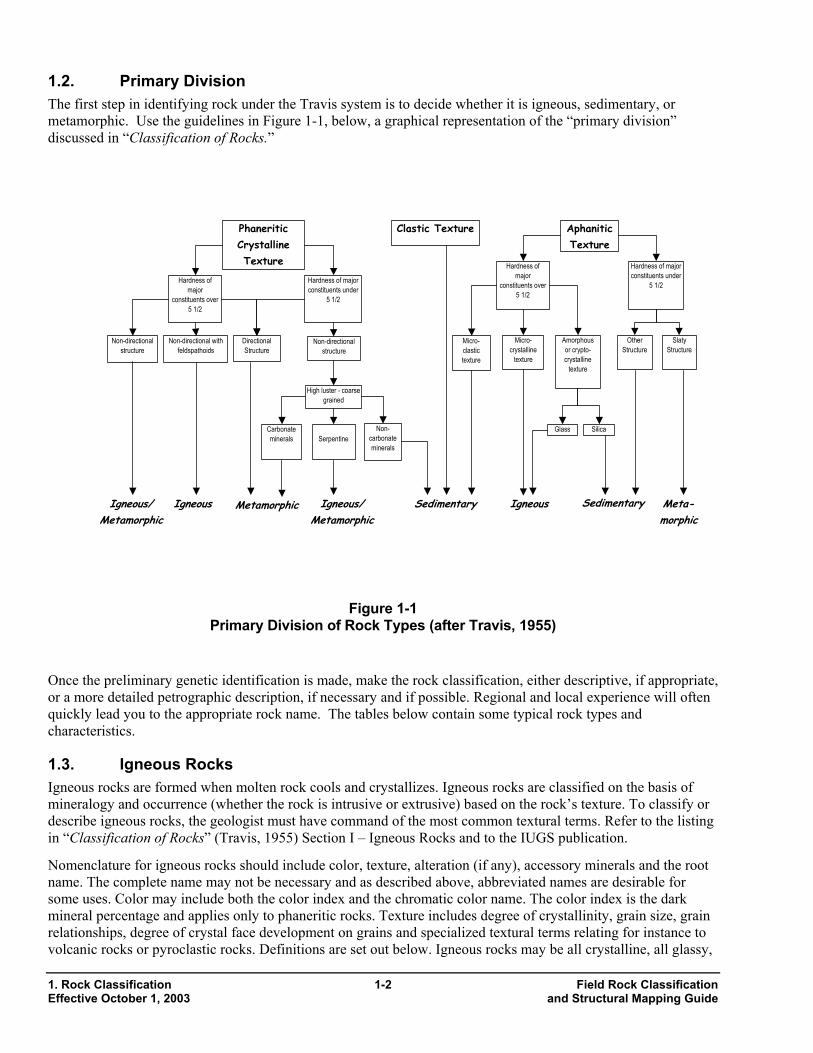
1.2. Primary Division The first step in identifying rock under the Travis system is to decide whether it is igneous, sedimentary, or metamorphic. Use the guidelines in Figure 1-1, below, a graphical representation of the “primary division” discussed in “Classification of Rocks.”
Phaneritic Crystalline Texture
Hardness of major
constituents over 5 1/2
Hardness of major constituents under
5 1/2
Clastic Texture Aphanitic Texture
Hardness of major
constituents over 5 1/2
Hardness of major constituents under
5 1/2
Sedimentary
Non-directional structure
Directional Structure
MetamorphicIgneousIgneous/ Metamorphic
Non-directional with feldspathoids
Non-directional structure
High luster - coarsegrained
Carbonate minerals Serpentine
Non-carbonate minerals
Meta-morphic
SedimentaryIgneous
Slaty Structure
Other Structure
Micro-crystalline
texture
Micro-clastic texture
Amorphous or crypto-crystalline
texture
Igneous/ Metamorphic
SilicaGlass
1-2 Field Rock Classification Effective October 1, 2003 and Structural Mapping Guide
Figure 1-1 Primary Division of Rock Types (after Travis, 1955)
Once the preliminary genetic identification is made, make the rock classification, either descriptive, if appropriate, or a more detailed petrographic description, if necessary and if possible. Regional and local experience will often quickly lead you to the appropriate rock name. The tables below contain some typical rock types and characteristics.
1.3. Igneous Rocks Igneous rocks are formed when molten rock cools and crystallizes. Igneous rocks are classified on the basis of mineralogy and occurrence (whether the rock is intrusive or extrusive) based on the rock’s texture. To classify or describe igneous rocks, the geologist must have command of the most common textural terms. Refer to the listing in “Classification of Rocks” (Travis, 1955) Section I – Igneous Rocks and to the IUGS publication.
Nomenclature for igneous rocks should include color, texture, alteration (if any), accessory minerals and the root name. The complete name may not be necessary and as described above, abbreviated names are desirable for some uses. Color may include both the color index and the chromatic color name. The color index is the dark mineral percentage and applies only to phaneritic rocks. Texture includes degree of crystallinity, grain size, grain relationships, degree of crystal face development on grains and specialized textural terms relating for instance to volcanic rocks or pyroclastic rocks. Definitions are set out below. Igneous rocks may be all crystalline, all glassy,
1. Rock Classification
or both. The grain size division is between rock with grains visible to the unaided eye and those with grain sizes smaller than can be seen with the unaided eye. Refer to Travis for a complete discussion.
1.3.1 Textural Definitions The igneous rocks can be described using a multitude of modifiers for texture. A partial listing includes:
General • Vesicular: spherical, ovoid or tubular openings
• Amygdaloidal: vesicles are filled with secondary minerals
Grain size • Aphanitic: grains not visible to the unaided eye (microcrystalline, cryptocrystalline or glassy)
• Phaneritic: grains visible to the unaided eye (coarse grained > 5mm, medium grained 1-5mm, or fine grained <1mm
Grain relationships • Granular: nearly equidimensional grains
• Porphyritic: grains of one or more sizes in a finer-grained groundmass
• Pegmatitic: grains of a wide range of sizes conspicuously larger than those of the parent rock
• Aplitic: composed of anhedral (no crystal faces) grains, sugary
Pyroclastic Rocks • Pumice: highly vesicular, finely cellular with tubular vesicles
• Scoria: highly vesicular, coarsely cellular, usually spherical vesicles
• Ash: includes glass shards, crystals and crystal fragments, stony or glassy rock fragments (sand to silt size - <2mm)
• Tuff: Rock name for rock with ash-sized cemented volcanic particles <2mm in size
• Lapilli: commonly pumice or scoria particles 2-64 mm in size (pebble size). The rock name is lapillistone.
• Tuff Breccia: ejected volcanic material >32 mm in size in an ash/tuff matrix
• Lapilli Tuff: ejected volcanic material 4-32 mm in size in ash/tuff matrix
• Blocks and Bombs: cobble and boulder size. Blocks are angular and rigid; bombs are plastic during eruption and are shaped to streamlined forms during flight. When indurated, the name is volcanic breccia or agglomerate.
Field Rock Classification 1-3 1. Rock Classification And Structural Mapping Guide Effective October 1, 2003
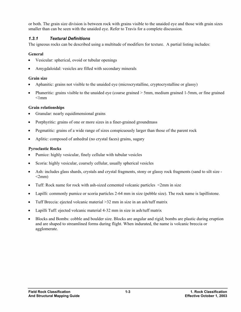
Table 1-1 Pyroclastic Rock Names
Particle Name Rock Names Particle Size Features Ash, cinders Lithic Tuff, Vitric Tuff, Crystal
Tuff, Welded Tuff <2 mm Ash-sized particles may be flows
from vent (poorly sorted) or falls from ejection into atmosphere (well sorted).
Lapilli Lapillstone, Lapilli breccia, Lapilli Tuff
2-64 mm Usually ejecta.
Blocks and Bombs
Pyroclastic breccia, agglomerate
>64 mm Usually ejecta.
Table 1-2 Porphyritic Rock Texture
Percent Phenocrysts Groundmass Texture
Under 12 12-50 50-75 Over 75 Phaneritic (grains visible)
Granite or Porphyritic
Granite
Granite Porphyry
Granite Porphyry
Granite
Aphanitic (grains not visible)
Rhyolite or Porphyritic
Rhyolite
Rhyolite Porphyry
Granite Porphyry
Granite
1.3.2 Color Index The color index is the percentage of dark minerals in the rock. Figure 1-2 on the next page (Travis, 1955 - Figure 1, Page 8) is a useful reference for determining color index. The terms “trap” and “felsite” are color terms for aphanitic rocks, with trap referring to dark rocks and felsite to light-colored rocks.
1. Rock Classification 1-4 Field Rock Classification Effective October 1, 2003 and Structural Mapping Guide
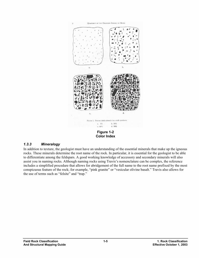
Figure 1-2
Color Index
1-5 1. Ro Effectiv
In addition to texture, the geologist must have an understanding of the essential minerals that make up the igneous rocks. These minerals determine the root name of the rock. In particular, it is essential for the geologist to be able to differentiate among the feldspars. A good working knowledge of accessory and secondary minerals will also assist you in naming rocks. Although naming rocks using Travis’s nomenclature can be complex, the reference includes a simplified procedure that allows for abridgement of the full name to the root name prefixed by the most conspicuous feature of the rock; for example, “pink granite” or “vesicular olivine basalt.” Travis also allows for the use of terms such as “felsite” and “trap.”
1.3.3 Mineralogy
Field Rock Classification ck Classification And Structural Mapping Guide e October 1, 2003
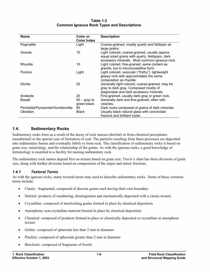
Table 1-3 Common Igneous Rock Types and Descriptions
Name Color or Color Index
Description
Pegmatite Light Coarse-grained, mostly quartz and feldspar as large grains.
Granite 10 Light colored, coarse-grained, usually approx. equal sized grains with quartz, feldspars, dark accessory minerals. Most common igneous rock.
Rhyolite 10 Light colored, fine-grained, same content as granite, but in microcrystalline form.
Pumice Light Light colored, vesicular (“frothy”), lightweight glassy rock with approximately the same composition as rhyolite.
Diorite 25 Generally light colored, coarse-grained, may be gray to dark gray. Composed mostly of plagioclase and dark accessory minerals.
Andesite 25 Fine-grained, usually dark gray or green rock. Basalt 50 – gray to
green-black Generally dark and fine-grained, often with vesicles.
Peridotite/Pyroxenite/Hornblendite 95 Dark rocks composed of grains of dark minerals. Obsidian Black Usually black natural glass with conchoidal
fracture and brilliant luster.
1.4. Sedimentary Rocks Sedimentary rocks form as a result of the decay of rock masses (detrital) or from chemical precipitates (nondetrital) or the special case of formation of coal. The particles resulting from these processes are deposited into sedimentary basins and eventually lithify to form rock. The classification of sedimentary rocks is based on grain size, mineralogy, and the relationship of the grains. As with the igneous rocks, a good knowledge of terminology is essential to a facility for naming sedimentary rock.
The sedimentary rock names depend first on texture based on grain size. Travis’s chart has three divisions of grain size, along with further divisions based on composition of the major and minor fractions.
1.4.1 Textural Terms As with the igneous rocks, many textural terms may used to describe sedimentary rocks. Some of these common terms include:
• Clastic: fragmental, composed of discrete grains each having their own boundary
• Detrital: products of weathering, disintegration and mechanically deposited with a clastic texture
• Crystalline: composed of interlocking grains formed in place by chemical deposition
• Amorphous: non-crystalline material formed in place by chemical deposition
• Chemical: composed of products formed in place or chemically deposited or crystalline or amorphous texture
• Oolitic: composed of spheroids less than 2 mm in diameter.
• Pisolitic: composed of spheroids greater than 2 mm in diameter
• Bioclastic: composed of fragments of fossils
1. Rock Classification 1-6 Field Rock Classification Effective October 1, 2003 and Structural Mapping Guide
1.4.2 Descriptive Terms Fissile: rock that may be readily split along closely spaced planes
Friable: rock or mineral that is easily broken, pulverized, or reduced to powder
Induration: the degree of hardening or consolidation or a rock (or soil) by heat, pressure, or cementing agents
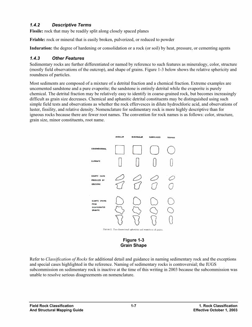
1.4.3 Other Features Sedimentary rocks are further differentiated or named by reference to such features as mineralogy, color, structure (mostly field observations of the outcrop), and shape of grains. Figure 1-3 below shows the relative sphericity and roundness of particles.
Most sediments are composed of a mixture of a detrital fraction and a chemical fraction. Extreme examples are uncemented sandstone and a pure evaporite; the sandstone is entirely detrital while the evaporite is purely chemical. The detrital fraction may be relatively easy to identify in coarse-grained rock, but becomes increasingly difficult as grain size decreases. Chemical and aphanitic detrital constituents may be distinguished using such simple field tests and observations as whether the rock effervesces in dilute hydrochloric acid, and observations of luster, fissility, and relative density. Nomenclature for sedimentary rock is more highly descriptive than for igneous rocks because there are fewer root names. The convention for rock names is as follows: color, structure, grain size, minor constituents, root name.
Figure 1-3 Grain Shape
Refer to Classification of Rocks for additional detail and guidance in naming sedimentary rock and the exceptions and special cases highlighted in the reference. Naming of sedimentary rocks is controversial; the IUGS subcommission on sedimentary rock is inactive at the time of this writing in 2003 because the subcommission was unable to resolve serious disagreements on nomenclature.
Field Rock Classification 1-7 1. Rock Classification And Structural Mapping Guide Effective October 1, 2003
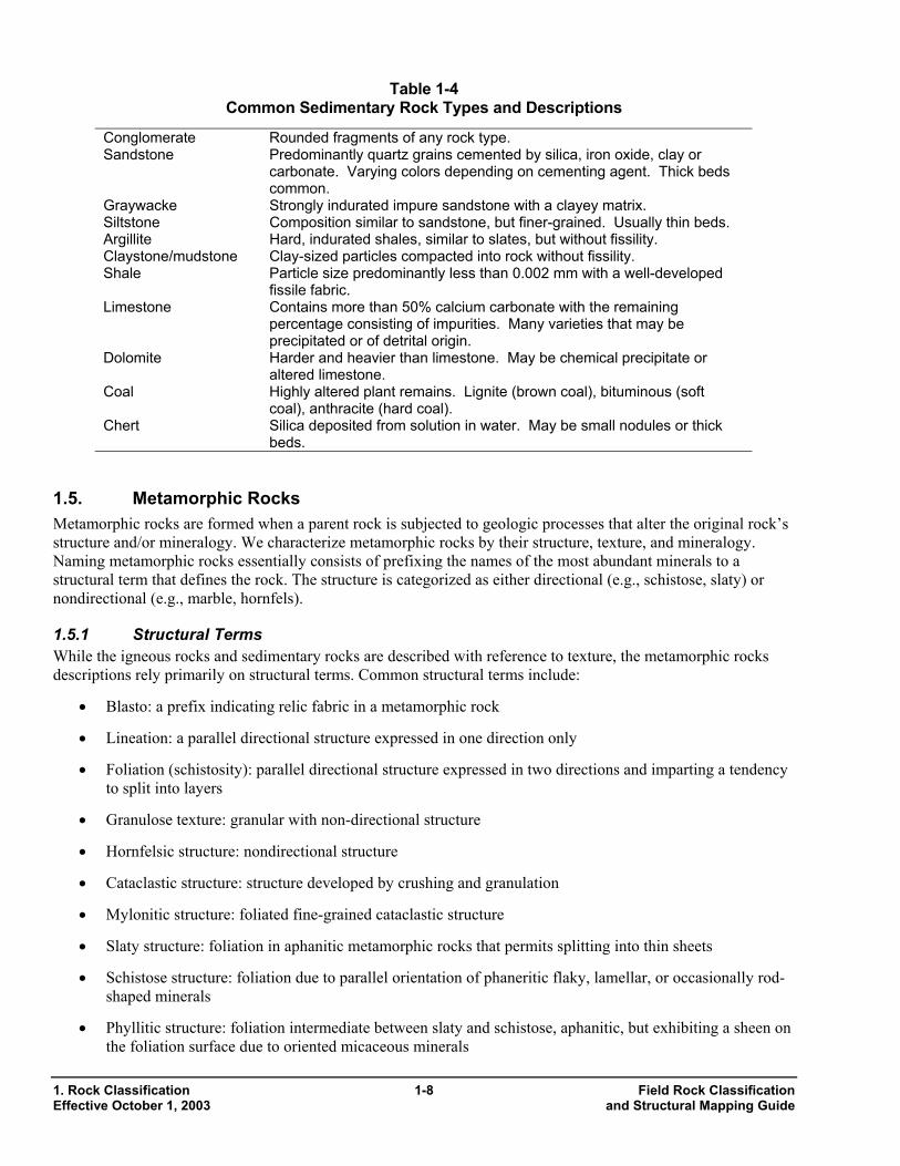
Table 1-4 Common Sedimentary Rock Types and Descriptions
Conglomerate Rounded fragments of any rock type. Sandstone Predominantly quartz grains cemented by silica, iron oxide, clay or
carbonate. Varying colors depending on cementing agent. Thick beds common.
Graywacke Strongly indurated impure sandstone with a clayey matrix. Siltstone Composition similar to sandstone, but finer-grained. Usually thin beds. Argillite Hard, indurated shales, similar to slates, but without fissility. Claystone/mudstone Clay-sized particles compacted into rock without fissility. Shale Particle size predominantly less than 0.002 mm with a well-developed
fissile fabric. Limestone Contains more than 50% calcium carbonate with the remaining
percentage consisting of impurities. Many varieties that may be precipitated or of detrital origin.
Dolomite Harder and heavier than limestone. May be chemical precipitate or altered limestone.
Coal Highly altered plant remains. Lignite (brown coal), bituminous (soft coal), anthracite (hard coal).
Chert Silica deposited from solution in water. May be small nodules or thick beds.
1.5. Metamorphic Rocks Metamorphic rocks are formed when a parent rock is subjected to geologic processes that alter the original rock’s structure and/or mineralogy. We characterize metamorphic rocks by their structure, texture, and mineralogy. Naming metamorphic rocks essentially consists of prefixing the names of the most abundant minerals to a structural term that defines the rock. The structure is categorized as either directional (e.g., schistose, slaty) or nondirectional (e.g., marble, hornfels).
1.5.1 Structural Terms While the igneous rocks and sedimentary rocks are described with reference to texture, the metamorphic rocks descriptions rely primarily on structural terms. Common structural terms include:
• Blasto: a prefix indicating relic fabric in a metamorphic rock
• Lineation: a parallel directional structure expressed in one direction only
• Foliation (schistosity): parallel directional structure expressed in two directions and imparting a tendency to split into layers
• Granulose texture: granular with non-directional structure
• Hornfelsic structure: nondirectional structure
• Cataclastic structure: structure developed by crushing and granulation
• Mylonitic structure: foliated fine-grained cataclastic structure
• Slaty structure: foliation in aphanitic metamorphic rocks that permits splitting into thin sheets
• Schistose structure: foliation due to parallel orientation of phaneritic flaky, lamellar, or occasionally rod-shaped minerals
• Phyllitic structure: foliation intermediate between slaty and schistose, aphanitic, but exhibiting a sheen on the foliation surface due to oriented micaceous minerals
1. Rock Classification 1-8 Field Rock Classification Effective October 1, 2003 and Structural Mapping Guide
• Gneissose structure: foliation due to alternation of granulose and schistose bands
• Migmatitic: a genetic term denoting mixed igneous and metamorphic origin; bands, veins, and pods of granitic rock in a metamorphic host rock
See Classification of Rocks (Travis, 1955) for a more complete discussion. Metamorphic rock-forming minerals are conveniently divided into two categories: essential minerals and characterizing accessory minerals. Travis provides a listing.
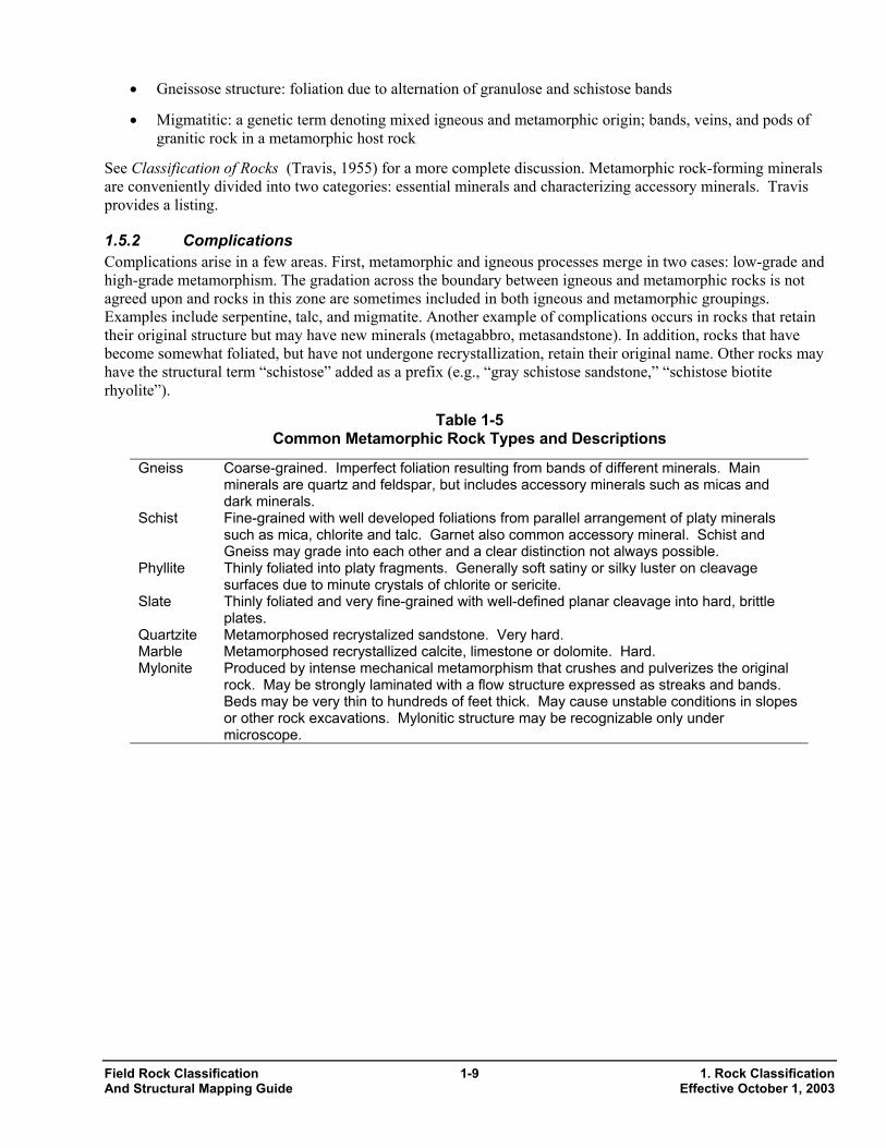
1.5.2 Complications Complications arise in a few areas. First, metamorphic and igneous processes merge in two cases: low-grade and high-grade metamorphism. The gradation across the boundary between igneous and metamorphic rocks is not agreed upon and rocks in this zone are sometimes included in both igneous and metamorphic groupings. Examples include serpentine, talc, and migmatite. Another example of complications occurs in rocks that retain their original structure but may have new minerals (metagabbro, metasandstone). In addition, rocks that have become somewhat foliated, but have not undergone recrystallization, retain their original name. Other rocks may have the structural term “schistose” added as a prefix (e.g., “gray schistose sandstone,” “schistose biotite rhyolite”).
Table 1-5 Common Metamorphic Rock Types and Descriptions
Gneiss Coarse-grained. Imperfect foliation resulting from bands of different minerals. Main minerals are quartz and feldspar, but includes accessory minerals such as micas and dark minerals.
Schist Fine-grained with well developed foliations from parallel arrangement of platy minerals such as mica, chlorite and talc. Garnet also common accessory mineral. Schist and Gneiss may grade into each other and a clear distinction not always possible.
Phyllite Thinly foliated into platy fragments. Generally soft satiny or silky luster on cleavage surfaces due to minute crystals of chlorite or sericite.
Slate Thinly foliated and very fine-grained with well-defined planar cleavage into hard, brittle plates.
Quartzite Metamorphosed recrystalized sandstone. Very hard. Marble Metamorphosed recrystallized calcite, limestone or dolomite. Hard. Mylonite Produced by intense mechanical metamorphism that crushes and pulverizes the original
rock. May be strongly laminated with a flow structure expressed as streaks and bands. Beds may be very thin to hundreds of feet thick. May cause unstable conditions in slopes or other rock excavations. Mylonitic structure may be recognizable only under microscope.
Field Rock Classification 1-9 1. Rock Classification And Structural Mapping Guide Effective October 1, 2003

2. Structural Characteristics of Rock 2.1. Introduction 2.2. Stability Analysis of Rock Masses 2.3. Rock Mass Classification and Description 2.4. Rock Quality 2.5. Rockfall Hazard and Slope Management 2.1. Introduction Rock mapping is of critical importance in projects where, for example, there is a high rock cut slope or where structural foundations are founded on rock, or where structures are anchored into rock. The minimum information includes rock type and the orientation of discontinuities. Rock type is important, among other reasons, as an indicator of strength characteristics, of the potential orientation of discontinuities, and of the potential for weathering. Along with rock type, the geologist maps the orientation and characteristics of the discontinuities in the rock mass, and determines the shape and size of blocks bounded by discontinuities following the techniques developed by the International Society of Rock Mechanics (ISRM, 1978) and discussed and summarized in “Rock Slopes” (Wyllie and Mah, 1998) and “Foundations on Rock” (Wyllie, 1999).
Mapping furnishes the fundamental information on site conditions. The data gathered during mapping are the basis for many subsequent engineering decisions including the location and type of structures and rock anchors, and the need for reinforcement of rock. The mapping is a vital part of the investigation, but is an inexact process because geological and engineering judgment is necessary to extrapolate from limited data from outcrops and cores that may represent only a small fraction of the affected rock mass.
The geologist uses the field data to identify the types of failures (planar, wedge, toppling, circular) that are kinematically possible in the rock by analysis of the discontinuity orientations with respect to the rock slope or structure using stereographic projections. Plot the discontinuity orientations along with the existing/proposed rock slope and analyze them to determine the potential direction of movement. Also obtain indication of the possible stability condition. If you identify one or more of the four potential failure modes, further analyze the likelihood of such failures. In addition to the geometric conditions established by stereographic projection analysis, analyze other factors to determine the stability of a rock slope. These other forces may include foundation loads, water conditions, and proposed reinforcement. Rigorous geological and engineering analysis supported by laboratory testing may be required to assess the stability of potentially unstable slopes.
2.2. Stability Analysis of Rock Masses Rock slope stability analysis is beyond the scope of this guide. However, a brief discussion is included here as an introduction. Department staff and consultants should follow state-of-the-practice procedures as represented by the references cited in this guide and other authoritative publications. We cannot overstate the importance of properly describing and analyzing the stability of a rock mass. In rock excavations, the rock slopes typically adjoin traveled ways. Failing rock slopes have caused disastrous losses of life and property. For bridge or retaining wall foundations on rock, the importance of understanding the structure and characteristics of the rock is equally obvious. The analysis of rock for foundation purposes must be a cooperative venture involving qualified engineers and geologists working together to reach an understanding of the nature of the rock material and how the rock mass will react to the forces imposed on it during and after construction.
The geologist or engineer who performs the structural analysis may use hand calculations using stereonets and stereographic projections, approved structural analysis software (e.g., RockPack, Dips, Swedge), and more sophisticated methods. For significant excavations, they should undertake a more rigorous study to determine whether the character of the discontinuities, strength of rock, presence of water in the slope, etc., indicate the potential for failures. If so, the geologist and engineer should consider the available means to mitigate the possibility of failure. Refer to FHWA’s “Rock Slopes” and Rockfall Hazards Mitigation Methods manual for guidance.
Field Rock Classification 2-1 2. Structural Characteristics of Rock And Structural Mapping Guide Effective October 1, 2003
2.3. Rock Mass Classification and Description There are numerous rock mass classification systems that have been developed for special purposes, such as tunneling, mining, and rock slope stability. ASTM Standard D 5878 contains a brief discussion of the some of these systems. The International Society of Rock Mechanics has developed a system discussed in Basic Geotechnical Description of Rock Masses (ISRM 1981). A discussion of several systems related to highway slopes is set out in “Rock Slopes” (Wyllie and Mah, 1998) and in Highway Rock Cut Stability Assessment in Rock Masses Not Conducive to Stability Calculations (Maerz, 2000).
Rock mass classification includes a description of in situ rock mass characteristics:
• Rock strength
• Weathering or alteration
• Hardness
• Discontinuity orientation and description
The procedures for a quantitative description of discontinuities in rock masses developed by the International Society of Rock Mechanics is published (ISRM 1977) and has been summarized and discussed in detail in Foundations on Rock (Wyllie, 1999). The procedures provide a language that enables geologists to transmit their observations of the rock mass and its anticipated behavior. The procedures provide quantitative data rather than subjective observations alone. The data obtained using the procedures are derived from simple measurements and provide a complete description of the rock mass for engineering purposes.
Thirteen rock mass properties may be examined and described quantitatively using the procedures. The characteristics that have importance for engineering design can be described in five categories (Wyllie, 1999), including:
• Rock material description (rock type, wall strength, weathering)
• Discontinuity description (type, orientation, roughness, aperture)
• Infilling (type, width)
• Rock mass description (spacing, persistence, number of sets, block size, and shape)
• Groundwater
The benefits of examining these characteristics and using these procedures are twofold: first, you discuss and quantitatively describe the parameters so the results can be used directly in design; second, the use of standardized procedures allows different personnel to use the procedures and interpret the results comparably. Figure 2-1, on the following page, provides an overview of the rock mapping criteria and their relationship to the rock mass.
2. Structural Characteristics of Rock 2-2 Field Rock Classification Effective October 1, 2003 and Structural Mapping Guide
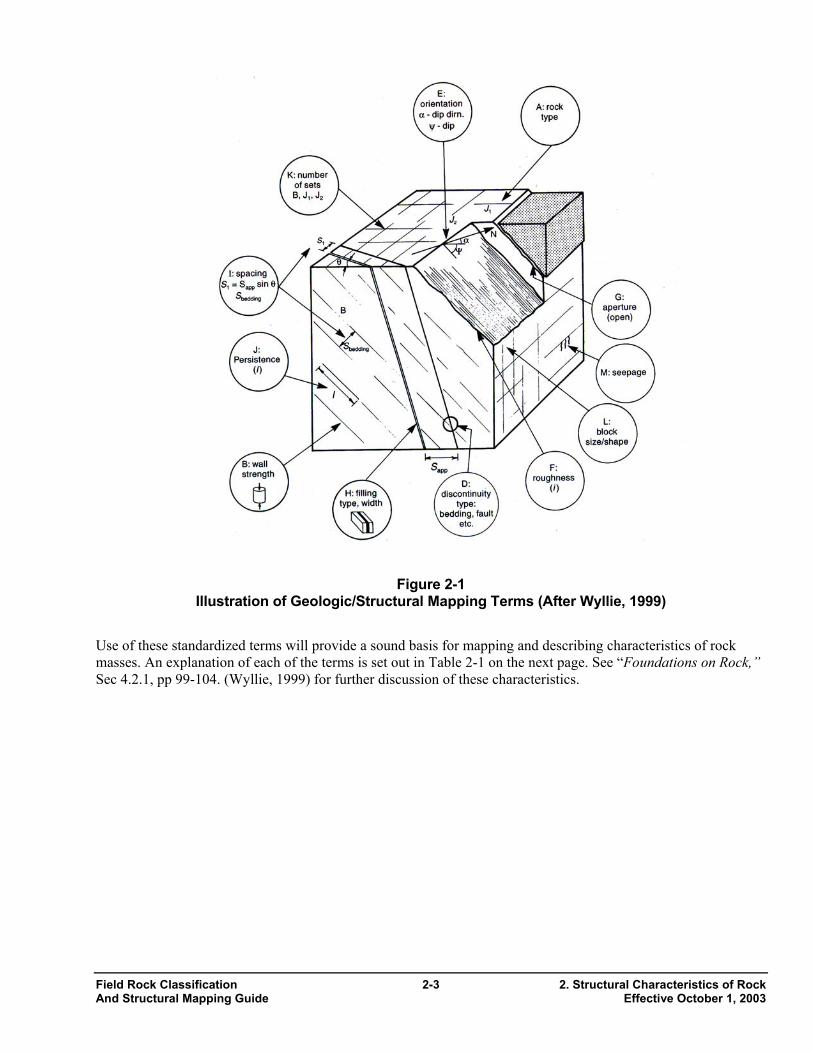
Figure 2-1
Illustration of Geologic/Structural Mapping Terms (After Wyllie, 1999)
Use of these standardized terms will provide a sound basis for mapping and describing characteristics of rock masses. An explanation of each of the terms is set out in Table 2-1 on the next page. See “Foundations on Rock,” Sec 4.2.1, pp 99-104. (Wyllie, 1999) for further discussion of these characteristics.
Field Rock Classification 2-3 2. Structural Characteristics of Rock And Structural Mapping Guide Effective October 1, 2003
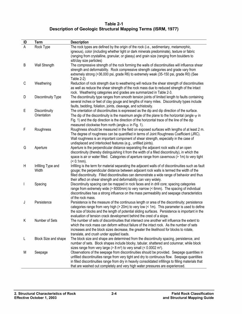
Table 2-1 Description of Geologic Structural Mapping Terms (ISRM, 1977)
ID Term Description A Rock Type The rock types are defined by the origin of the rock (i.e., sedimentary, metamorphic,
igneous), color (including whether light or dark minerals predominate), texture or fabric (ranging from crystalline, granular, or glassy) and grain size (ranging from boulders to silt/clay size particles)
B Wall Strength The compressive strength of the rock forming the walls of discontinuities will influence shear strength and deformability. Rock compressive strength categories and grade vary from extremely strong (>36,000 psi, grade R6) to extremely weak (35-150 psi, grade R0) (See Table 2-2)
C Weathering Reduction of rock strength due to weathering will reduce the shear strength of discontinuities as well as reduce the shear strength of the rock mass due to reduced strength of the intact rock. Weathering categories and grades are summarized in Table 2-3.
D Discontinuity Type The discontinuity type ranges from smooth tension joints of limited length to faults containing several inches or feet of clay gouge and lengths of many miles. Discontinuity types include faults, bedding, foliation, joints, cleavage, and schistosity.
E Discontinuity Orientation
The orientation of discontinuities is expressed as the dip and dip direction of the surface. The dip of the discontinuity is the maximum angle of the plane to the horizontal (angle ψ in Fig. 1) and the dip direction is the direction of the horizontal trace of the line of the dip measured clockwise from north (angle α in Fig. 1).
F Roughness Roughness should be measured in the field on exposed surfaces with lengths of at least 2 m. The degree of roughness can be quantified in terms of Joint Roughness Coefficient (JRC). Wall roughness is an important component of shear strength, especially in the case of undisplaced and interlocked features (e.g., unfilled joints).
G Aperture Aperture is the perpendicular distance separating the adjacent rock walls of an open discontinuity (thereby distinguishing it from the width of a filled discontinuity), in which the space is air or water filled. Categories of aperture range from cavernous (> 1m) to very tight (< 0.1mm).
H Infilling Type and Width
Infilling is the term for material separating the adjacent walls of of discontinuities such as fault gouge; the perpendicular distance between adjacent rock walls is termed the width of the filled discontinuity. Filled discontinuities can demonstrate a wide range of behavior and thus their affect on shear strength and deformability can vary widely.
I Spacing Discontinuity spacing can be mapped in rock faces and in drill core; spacing categories range from extremely wide (> 6000mm) to very narrow (< 6mm). The spacing of individual discontinuities has a strong influence on the mass permeability and seepage characteristics of the rock mass.
J Persistence Persistence is the measure of the continuous length or area of the discontinuity; persistence categories range from very high (> 20m) to very low (< 1m). This parameter is used to define the size of blocks and the length of potential sliding surfaces. Persistence is important in the evaluation of tension crack development behind the crest of a slope.
K Number of Sets The number of sets of discontinuities that intersect one another will influence the extent to which the rock mass can deform without failure of the intact rock. As the number of sets increases and the block sizes decrease, the greater the likelihood for blocks to rotate, translate, and crush under applied loads.
L Block Size and shape The block size and shape are determined from the discontinuity spacing, persistence, and number of sets. Block shapes include blocky, tabular, shattered and columnar, while block sizes range from very large (> 8 m3) to very small (< 0.0002 m3).
M Seepage Observations of the seepage from discontinuities should be provided. Seepage quantities in unfilled discontinuities range from very tight and dry to continuous flow. Seepage quantities in filled discontinuities range from dry in heavily consolidated infillings to filling materials that that are washed out completely and very high water pressures are experienced.
2. Structural Characteristics of Rock 2-4 Field Rock Classification Effective October 1, 2003 and Structural Mapping Guide
2.3.1 Rock Type (“A”) This feature was discussed above in the rock classification section. Such characteristics of rock as strength and presence of discontinuities may be controlled to some degree by the rock type.
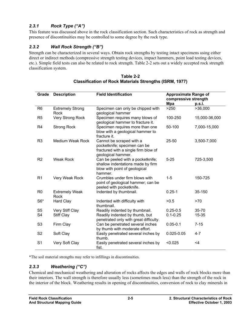
2.3.2 Wall Rock Strength (“B”) Strength can be characterized in several ways. Obtain rock strengths by testing intact specimens using either direct or indirect methods (compressive strength testing devices, impact hammers, point load testing devices, etc.). Simple field tests can also be related to rock strength. Table 2-2 sets out a widely accepted rock strength classification system.
Table 2-2 Classification of Rock Materials Strengths (ISRM, 1977)
Approximate Range of compressive strength
Grade Description Field Identification
Mpa p.s.i. R6 Extremely Strong
Rock Specimen can only be chipped with geological hammer
>250 >36,000
R5 Very Strong Rock Specimen requires many blows of geological hammer to fracture it.
100-250 15,000-36,000
R4 Strong Rock Specimen requires more than one blow with a geological hammer to fracture it.
50-100 7,000-15,000
R3 Medium Weak Rock Cannot be scraped with a pocketknife; specimen can be fractured with a single firm blow of geological hammer.
25-50 3,500-7,000
R2 Weak Rock Can be peeled with a pocketknife; shallow indentations made by firm blow with point of geological hammer.
5-25 725-3,500
R1 Very Weak Rock Crumbles under firm blows with point of geological hammer; can be peeled with pocketknife.
1-5 150-725
R0 Extremely Weak Rock
Indented by thumbnail. 0.25-1 35-150
S6* Hard Clay Indented with difficulty with thumbnail.
>0.5 >70
S5 Very Stiff Clay Readily indented by thumbnail. 0.25-0.5 35-70 S4 Stiff Clay Readily indented by thumb, but
penetrated only with great difficulty. 0.1-0.25 15-35
S3 Firm Clay Can be penetrated several inches by thumb with moderate effort.
0.05-0.1 7-15
S2 Soft Clay Easily penetrated several inches by thumb.
0.025-0.05 4-7
S1 Very Soft Clay Easily penetrated several inches by fist.
<0.025 <4
*The soil material strengths may refer to infillings in discontinuities.
2.3.3 Weathering (“C”) Chemical and mechanical weathering and alteration of rocks affects the edges and walls of rock blocks more than their interiors. The wall strength is therefore usually less (sometimes much less) than the strength of the rock in the interior of the block. Weathering results in opening of discontinuities, conversion of rock to clay minerals in
Field Rock Classification 2-5 2. Structural Characteristics of Rock And Structural Mapping Guide Effective October 1, 2003
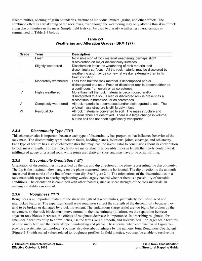
discontinuities, opening of grain boundaries, fracture of individual mineral grains, and other effects. The combined effect is a weakening of the rock mass, even though the weathering may only affect a thin skin of rock along discontinuities in the mass. Simple field tests can be used to classify weathering characteristics as summarized in Table 2-3 below.
Table 2-3 Weathering and Alteration Grades (ISRM 1977)
Grade Term Description I Fresh No visible sign of rock material weathering; perhaps slight
discoloration on major discontinuity surfaces. II Slightly weathered Discoloration indicates weathering of rock material and
discontinuity surfaces. All the rock material may be discolored by weathering and may be somewhat weaker externally than in its fresh condition.
III Moderately weathered Less than half the rock material is decomposed and/or disintegrated to a soil. Fresh or discolored rock is present either as a continuous framework or as corestones.
IV Highly weathered More than half the rock material is decomposed and/or disintegrated to a soil. Fresh or discolored rock is present as a discontinuous framework or as corestones.
V Completely weathered All rock material is decomposed and/or disintegrated to soil. The original mass structure is still largely intact.
VI Residual Soil All rock material is converted to soil. The mass structure and material fabric are destroyed. There is a large change in volume, but the soil has not been significantly transported.
2.3.4 Discontinuity Type (“D”) This characteristics is important because each type of discontinuity has properties that influence behavior of the rock mass. The discontinuity types include: faults, bedding planes, foliations, joints, cleavage, and schistosity. Each type of feature has a set of characteristics that may lead the investigator to conclusions about its contribution to rock mass strength. For example, faults are major structures possibly miles in length that likely contain weak infillings of gouge or crushed rock, while joints are relatively short and may have little or no infilling.
2.3.5 Discontinuity Orientation (“E”) Orientation of discontinuities is described by the dip and dip direction of the plane representing the discontinuity. The dip is the maximum down angle on the plane measured from the horizontal. The dip direction is the azimuth (measured from north) of the line of maximum dip. See Figure 2-1. The orientations of the discontinuities in a rock mass with respect to nearby engineering works largely control whether there is a possibility of unstable conditions. The orientation is combined with other features, such as shear strength of the rock materials, in making a stability assessment.
2.3.6 Roughness (“F”) Roughness is an important feature of the shear strength of discontinuities, particularly for undisplaced and interlocked features. The asperities (small scale roughness) affect the strength of the discontinuity because they tend to be broken or damaged by block movement. The undulations (large scale) are too big to be broken by the movement, so the rock blocks must move normal to the discontinuity (dilation). As the separation between adjacent rock blocks increases, the effects of roughness decrease in importance. In describing roughness, for small-scale features of up to a few inches, use the terms rough, smooth, and slickensided. For larger scale features of up to many feet, use the terms stepped, undulating and planar. These terms, when combined as in Figure 2-2, provide a systematic terminology. You may also describe roughness by the numeric Joint Roughness Coefficient (Figure 2-3) with scaled values related to roughness profiles. In field practice, you may be unable to resolve the
2. Structural Characteristics of Rock 2-6 Field Rock Classification Effective October 1, 2003 and Structural Mapping Guide
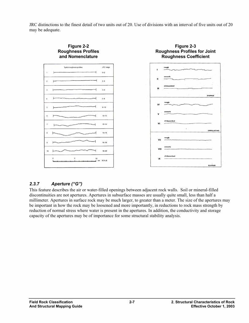
JRC distinctions to the finest detail of two units out of 20. Use of divisions with an interval of five units out of 20 may be adequate.
Figure 2-2 Roughness Profiles and Nomenclature
Figure 2-3 Roughness Profiles for Joint
Roughness Coefficient
2.3.7 Aperture (“G”) This feature describes the air or water-filled openings between adjacent rock walls. Soil or mineral-filled discontinuities are not apertures. Apertures in subsurface masses are usually quite small, less than half a millimeter. Apertures in surface rock may be much larger, to greater than a meter. The size of the apertures may be important in how the rock may be loosened and more importantly, in reductions to rock mass strength by reduction of normal stress where water is present in the apertures. In addition, the conductivity and storage capacity of the apertures may be of importance for some structural stability analysis.
Field Rock Classification 2-7 2. Structural Characteristics of Rock And Structural Mapping Guide Effective October 1, 2003
2. Structural Characteristics of Rock 2-8 Field Rock Classification Effective October 1, 2003 and Structural Mapping Guide
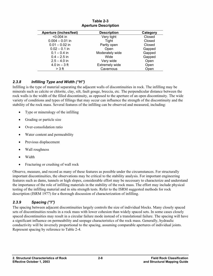
Table 2-3 Aperture Description
Aperture (inches/feet) Description Category <0.004 in Very tight Closed
0.004 – 0.01 in Tight Closed 0.01 – 0.02 in Partly open Closed 0.02 – 0.1 in Open Gapped 0.1 – 0.4 in Moderately wide Gapped 0.4 – 2.5 in Wide Gapped 2.5 – 4.0 in Very wide Open 4.0 in – 3 ft Extremely wide Open
> 3 ft Cavernous Open
2.3.8 Infilling Type and Width (“H”) Infilling is the type of material separating the adjacent walls of discontinuities in rock. The infilling may be minerals such as calcite or chlorite, clay, silt, fault gouge, breccia, etc. The perpendicular distance between the rock walls is the width of the filled discontinuity, as opposed to the aperture of an open discontinuity. The wide variety of conditions and types of fillings that may occur can influence the strength of the discontinuity and the stability of the rock mass. Several features of the infilling can be observed and measured, including:
• Type or mineralogy of the infilling
• Grading or particle size
• Over-consolidation ratio
• Water content and permeability
• Previous displacement
• Wall roughness
• Width
• Fracturing or crushing of wall rock
Observe, measure, and record as many of these features as possible under the circumstances. For structurally important discontinuities, the observations may be critical to the stability analysis. For important engineering features such as dams, tunnels or high slopes, considerable effort may be necessary to characterize and understand the importance of the role of infilling materials in the stability of the rock mass. The effort may include physical testing of the infilling material and in situ strength tests. Refer to the ISRM suggested methods for rock description (ISRM 1977) for a thorough discussion of characterization of infilling.
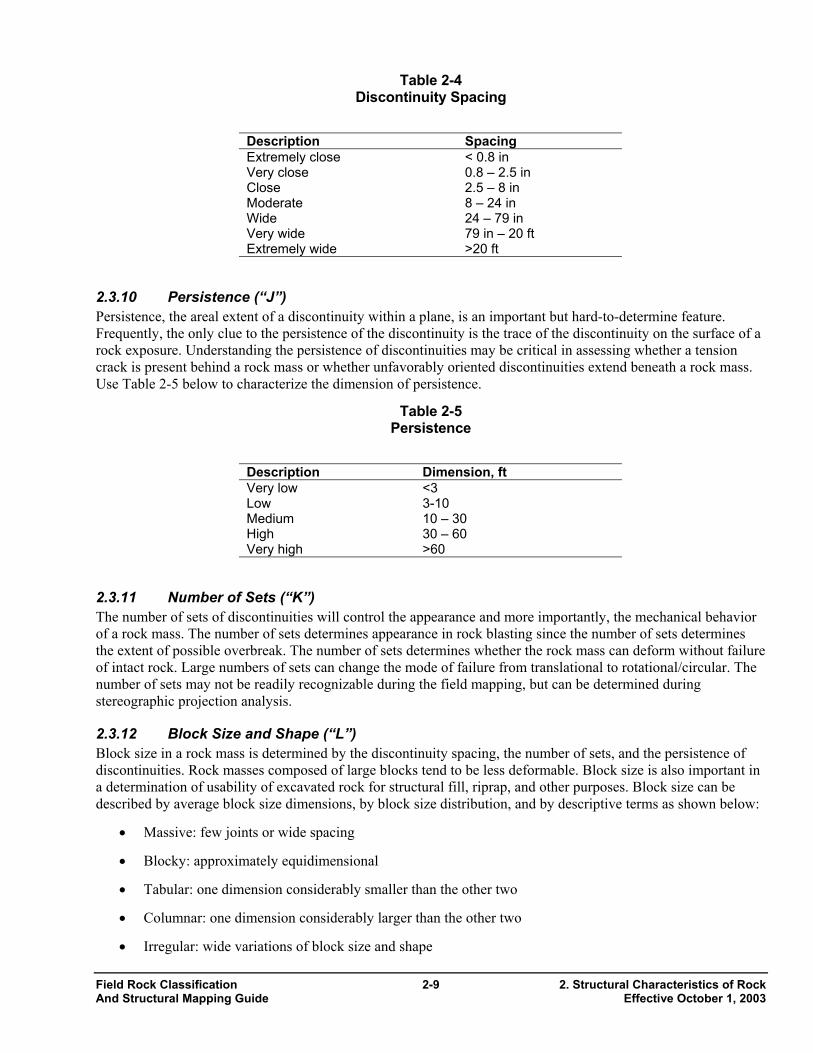
2.3.9 Spacing (“I”) The spacing between adjacent discontinuities largely controls the size of individual blocks. Many closely spaced sets of discontinuities results in a rock mass with lower cohesion than widely spaced sets. In some cases closely spaced discontinuities may result in a circular failure mode instead of a translational failure. The spacing will have a significant influence on permeability and seepage characteristics of the rock mass. Generally, hydraulic conductivity will be inversely proportional to the spacing, assuming comparable apertures of individual joints. Represent spacing by reference to Table 2-4.
Field Rock Classification 2-9 2. Structural Characteristics of Rock And Structural Mapping Guide Effective October 1, 2003
Table 2-4 Discontinuity Spacing
Description Spacing Extremely close < 0.8 in Very close 0.8 – 2.5 in Close 2.5 – 8 in Moderate 8 – 24 in Wide 24 – 79 in Very wide 79 in – 20 ft Extremely wide >20 ft
2.3.10 Persistence (“J”) Persistence, the areal extent of a discontinuity within a plane, is an important but hard-to-determine feature. Frequently, the only clue to the persistence of the discontinuity is the trace of the discontinuity on the surface of a rock exposure. Understanding the persistence of discontinuities may be critical in assessing whether a tension crack is present behind a rock mass or whether unfavorably oriented discontinuities extend beneath a rock mass. Use Table 2-5 below to characterize the dimension of persistence.
Table 2-5 Persistence
Description Dimension, ft Very low <3 Low 3-10 Medium 10 – 30 High 30 – 60 Very high >60
2.3.11 Number of Sets (“K”) The number of sets of discontinuities will control the appearance and more importantly, the mechanical behavior of a rock mass. The number of sets determines appearance in rock blasting since the number of sets determines the extent of possible overbreak. The number of sets determines whether the rock mass can deform without failure of intact rock. Large numbers of sets can change the mode of failure from translational to rotational/circular. The number of sets may not be readily recognizable during the field mapping, but can be determined during stereographic projection analysis.
2.3.12 Block Size and Shape (“L”) Block size in a rock mass is determined by the discontinuity spacing, the number of sets, and the persistence of discontinuities. Rock masses composed of large blocks tend to be less deformable. Block size is also important in a determination of usability of excavated rock for structural fill, riprap, and other purposes. Block size can be described by average block size dimensions, by block size distribution, and by descriptive terms as shown below:
• Massive: few joints or wide spacing
• Blocky: approximately equidimensional
• Tabular: one dimension considerably smaller than the other two
• Columnar: one dimension considerably larger than the other two
• Irregular: wide variations of block size and shape
2. Structural Characteristics of Rock 2-10 Field Rock Classification Effective October 1, 2003 and Structural Mapping Guide
• Crushed: heavily jointed
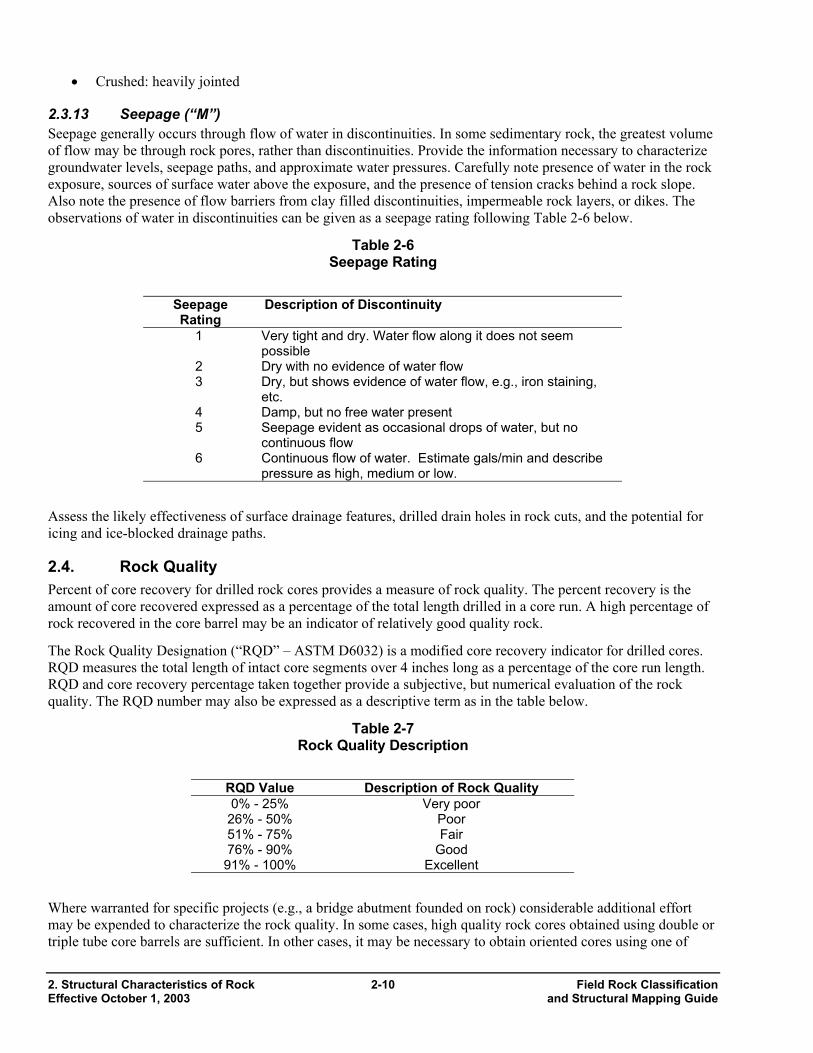
2.3.13 Seepage (“M”) Seepage generally occurs through flow of water in discontinuities. In some sedimentary rock, the greatest volume of flow may be through rock pores, rather than discontinuities. Provide the information necessary to characterize groundwater levels, seepage paths, and approximate water pressures. Carefully note presence of water in the rock exposure, sources of surface water above the exposure, and the presence of tension cracks behind a rock slope. Also note the presence of flow barriers from clay filled discontinuities, impermeable rock layers, or dikes. The observations of water in discontinuities can be given as a seepage rating following Table 2-6 below.
Table 2-6 Seepage Rating
Seepage Rating
Description of Discontinuity
1 Very tight and dry. Water flow along it does not seem possible
2 Dry with no evidence of water flow 3 Dry, but shows evidence of water flow, e.g., iron staining,
etc. 4 Damp, but no free water present 5 Seepage evident as occasional drops of water, but no
continuous flow 6 Continuous flow of water. Estimate gals/min and describe
pressure as high, medium or low.
Assess the likely effectiveness of surface drainage features, drilled drain holes in rock cuts, and the potential for icing and ice-blocked drainage paths.
2.4. Rock Quality Percent of core recovery for drilled rock cores provides a measure of rock quality. The percent recovery is the amount of core recovered expressed as a percentage of the total length drilled in a core run. A high percentage of rock recovered in the core barrel may be an indicator of relatively good quality rock.
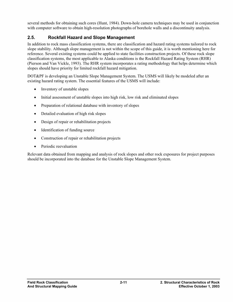
The Rock Quality Designation (“RQD” – ASTM D6032) is a modified core recovery indicator for drilled cores. RQD measures the total length of intact core segments over 4 inches long as a percentage of the core run length. RQD and core recovery percentage taken together provide a subjective, but numerical evaluation of the rock quality. The RQD number may also be expressed as a descriptive term as in the table below.
Table 2-7 Rock Quality Description
RQD Value Description of Rock Quality 0% - 25% Very poor
26% - 50% Poor 51% - 75% Fair 76% - 90% Good 91% - 100% Excellent
Where warranted for specific projects (e.g., a bridge abutment founded on rock) considerable additional effort may be expended to characterize the rock quality. In some cases, high quality rock cores obtained using double or triple tube core barrels are sufficient. In other cases, it may be necessary to obtain oriented cores using one of
Field Rock Classification 2-11 2. Structural Characteristics of Rock And Structural Mapping Guide Effective October 1, 2003
several methods for obtaining such cores (Hunt, 1984). Down-hole camera techniques may be used in conjunction with computer software to obtain high-resolution photographs of borehole walls and a discontinuity analysis.
2.5. Rockfall Hazard and Slope Management In addition to rock mass classification systems, there are classification and hazard rating systems tailored to rock slope stability. Although slope management is not within the scope of this guide, it is worth mentioning here for reference. Several existing systems could be applied to state facilities construction projects. Of these rock slope classification systems, the most applicable to Alaska conditions is the Rockfall Hazard Rating System (RHR) (Pierson and Van Vickle, 1993). The RHR system incorporates a rating methodology that helps determine which slopes should have priority for limited rockfall hazard mitigation.
DOT&PF is developing an Unstable Slope Management System. The USMS will likely be modeled after an existing hazard rating system. The essential features of the USMS will include:
• Inventory of unstable slopes
• Initial assessment of unstable slopes into high risk, low risk and eliminated slopes
• Preparation of relational database with inventory of slopes
• Detailed evaluation of high risk slopes
• Design of repair or rehabilitation projects
• Identification of funding source
• Construction of repair or rehabilitation projects
• Periodic reevaluation
Relevant data obtained from mapping and analysis of rock slopes and other rock exposures for project purposes should be incorporated into the database for the Unstable Slope Management System.

3. Structural Rock Mapping Procedures 3.1. Introduction 3.2. Critical Features Mapping 3.3. Line Mapping 3.4. Window Mapping 3.5. Mapping Procedure 3.1. Introduction There are many ways to map rock. The most suitable method for one rock exposure and one type of facility will be inappropriate for another exposure or a different project. The objective is to use procedures that define, and then successively refine, information on those features that will be critical to stability (Wyllie, 1998). The Department follows guidance from the ISRM source materials, the FHWA manual Rock Slopes, and Foundations on Rock as discussed above. Other useful references are listed at the beginning of this guide.
The best quality mapping is produced by a team of professionals using the right tools and open minds. Before detailed mapping, first study the regional geology and topography and how the local geology fits the regional scheme. Next, examine the rock exposure from a distance, if possible, and place it in the context of the local geology. Finally, examine the exposure from close up and perform the detailed mapping as laid out below.
Follow a flexible procedure in mapping and describing rock exposures. The nature of the project and field conditions will dictate, to some extent, the field procedure, and you must remain flexible enough to modify the mapping plan to suit the conditions and findings as they are developed. It is important to integrate and synthesize data into preliminary conclusions as the mapping progresses. By the time you leave the field, you should have a thorough understanding of the key elements of the rock exposure. The office analysis will usually confirm what you have concluded about the rock, but as the data are plotted and the analysis is developed, there will occasionally be surprises. With this in mind, it is a good idea to plan for one or more re-visits for additional mapping, especially on projects where the consequences of error are significant.
Rock mapping can be subdivided into two different types and several different levels of detail. Rock mapping can be either subjective (biased) or objective (random). The subjective survey describes only the discontinuities that appear important. The objective survey describes all discontinuities that intersect a fixed line or area of rock exposure (ISRM, 1978). Differing levels of detail are represented in critical features mapping, window mapping, and line mapping (Wyllie and Mah, Appendix I, 1998). The distinctions between these levels of detail in mapping are not sharp and you should carefully select the best methodology for obtaining the necessary information.
Choose the methodology of mapping to meet the project requirements, the conditions at the site, and limitations on time and money for investigations. Choose among three specific mapping types: critical features mapping, window mapping, and line mapping. Often, the best choice for the Department’s structural mapping will be subjective (biased) joint set and critical features mapping. There will be circumstances where window mapping or line mapping may be useful. However, critical features mapping gives you the most flexibility in observation and preliminary analysis during the field mapping process. This in turn produces a focused mapping effort and relies on your analytical skills, rather than on statistical analysis of random data. Objective (random) surveys are time consuming, inflexible, and often fail to produce a statistically significant volume of data.
Where time or budget constraints preclude a complete detailed mapping effort, the mapping should be prioritized in the following order:
• Orientation and location of major faults and weak zones
• Orientation and location of contacts between major rock types
• Orientation of persistent discontinuities
Field Rock Classification 3-1 3. Structural Rock Mapping Procedures And Structural Mapping Guide Effective October 1, 2003
• Spacing of persistent discontinuities
• Infilling of persistent discontinuities
• Surface properties of discontinuities
Generalized feature mapping consists of locating and describing features such as faults, rock type contacts (including weathering and alteration), fold axes, prominent bedding planes, foliations, and joint sets. The orientation of the features is measured using a structural compass and recorded. If there is adequate time the mapping can include brief notes on infillings, displacement, presence of water, etc. Once you have the larger picture in mind, the next step is a more detailed look. Detailed mapping includes critical features mapping, window mapping, and line mapping. Each method has its place. After the major features have been mapped and considered, determine what features or areas warrant detailed mapping. It is not desirable to map every feature in an exposure. Such detailed mapping can be wasteful and misleading and may produce data points for minor features that have no effect on stability. Such irrelevant data points can skew the data, if not carefully filtered out in the analysis. Features that are persistent or have unfavorable orientations should always be included.
Record the important features on a plan set to show the location with respect to the project features. Representative oriented data should also be plotted by hand in the field on stereonets so you can see the stereonet and the rock exposure at the same time. In the office, you can process the bulk of the data through versatile and time-saving structural analysis software such as Dips, Swedge, or RockPack.
3.2. Critical Features Mapping Here, detailed mapping is undertaken for specific features that are critical to stability. For instance, analysis of preliminary data from a rock slope may reveal the necessity of determining characteristics of an unfavorably oriented joint set that is critical for understanding stability. Following the mapping plan developed under the section on “Mapping Procedures” below, make careful measurements or estimates of spacing, strength of the joint infilling along with roughness and other characteristics that may be required to determine the stability of the rock mass.
Mapping joint sets produces data about a set of joints including location, discontinuity type, orientation, spacing, persistence, infillings, and surface properties. Identify and locate by reference to centerline or other surveyed points the structural zones or domains in the exposed rock. In each identifiable structural zone or domain, map discontinuity sets for location, type, orientation, spacing, persistence, infilling, and surface properties. Take enough measurement to establish a consistent range of values for each data set.
3.3. Line Mapping In this method, a surveyed or accurately located line is established along all or part of the exposure, and every feature that intersects the line is mapped and described following the mapping plan and procedures set out under “Mapping Procedures” in the following section. This method is tedious and leaves little room for flexibility or analysis as the data collection is under way. Take enough measurements for each discontinuity set to achieve a statistically valid basis for analysis. This may not be feasible where the exposure is small. If it is not possible to delineate clear joint sets, map only features that are persistent or are adversely orientated.
3.4. Window Mapping In this method, detailed mapping is performed in selected representative windows at intervals along an exposure. Intervening areas are reviewed for similarity; significant variations or features in these areas may also be mapped. In each window, record the mean orientation and characteristics for each discontinuity set. Choose the size and interval of the windows to suit the project; for rock slopes, a typical layout is 5 feet by 30 feet windows centered every 150 feet. Select the location for mapping and mark the boundaries. Locate the window by station and offset or state plane coordinates, using survey methods or GPS. Observe and describe the material and structural features within the window, following the mapping procedures in the following section.
3. Structural Rock Mapping Procedures 3-2 Field Rock Classification Effective October 1, 2003 and Structural Mapping Guide
3.5. Mapping Procedure 3.5.1 Review Available Information • Obtain and familiarize yourself with the plan sheets, cross sections and other available information before
going into the field.
• Obtain and review geological reports and maps, air photos, previous geotechnical reports, etc., before going to the field.
• Identify potential problem areas such as high cuts, retaining wall sites, thick overburden, poor quality rock, fault zones, etc.
• Consider impact to nearby structures and topography inside and outside the right-of-way.
• At a minimum, take plan sheets and cross sections to the field.
• If possible, take topographic maps, proposed cut and fill slope limits, geologic maps, soil maps, etc.
3.5.2 Prepare Rock Mapping Plan Following is an idealized plan for conducting mapping. Each project will require modification to this generalized plan, so don’t rely on this as an all-inclusive checklist.
The first step is to identify the area of interest in a project. Conduct such office reconnaissance as is possible to identify the scope of work necessary to obtain geotechnical data needed for design. Obtain and examine air photos, geologic maps, hazard maps, project drawings, geologic survey reports, previous Department reports, etc.
•
•
•
•
•
•
•
•
•
•
If necessary and feasible, conduct a brief field reconnaissance to establish the methods of mapping and fieldwork.
Select a mapping technique suitable for the project and the field conditions. This decision may be made in the field.
Begin field exploration. Examine the exposures starting with gross features and the “big picture” and work toward more detailed looks at smaller areas.
Identify and mark, if necessary, the area or areas for mapping.
Locate the area(s) in relation to geographic reference points, whether stationing, temporary reference stations, or GPS coordinates.
Establish a baseline for locating measurements within the mapping box. Describe the orientation of the baseline and its relationship with prominent features, with centerline and the trend of the cut or with the planned structure footprint, if available. Make sure the “north” used for field mapping is the same “north” used in developing project plans. Set compasses at “0” declination for field mapping and normalize the data to the proper declination as a step in the office analysis procedure (This may complicate the preparation of field stereonets).
At the appropriate level of effort, measure the orientation of discontinuities and their location with respect to the baseline.
Describe the discontinuities and the rock mass using the ISRM guidelines to describe the various characteristics.
Photograph the rock cut or exposure from a distance, if possible, and in as many close-ups or intermediate shots as necessary to record the necessary details. A digital camera with a preview screen is an invaluable tool for this purpose. Make sketches if helpful.
Field Rock Classification 3-3 3. Structural Rock Mapping Procedures And Structural Mapping Guide Effective October 1, 2003
3.5.3 Conduct Mapping According to Plan • Record general views and details of the rock exposure for the existing exposure and the proposed cut. For
photographs, use an appropriate scale in the photo, such as a stake or lathe painted contrasting colors at one-foot increments. The photos and sketch of the exposure will be a valuable aid for refreshing your memory during the analysis phase, after completion of the field work.
• Starting from the regional level and working toward more localized detail, summarize the geologic setting of the exposure in the context of regional and local geology and topography.
• Locate the exposure with respect to the project stationing or survey grid.
• Measure and record the shape of the existing cut or exposure. At a minimum, record length of exposure or cut, height at several locations, and existing slope angle.
• Observe and record details about existing rockfall, surface drainage, springs in rock exposures, effectiveness of existing ditch, apparent extent of weathering of exposed rock surfaces, existing slope angles, blast damage from original construction, evidence of previous blasting methods, presence of nearby facilities, structures, streams, or other features that might be affected by construction.
• Describe zones of similar conditions in the rock exposure by rock type and other obvious characteristics.
• Observe and record major discontinuity sets.
• Identify windows or scan lines for detailed mapping.
• Using the ISRM-based mapping forms, characterize the rock, identify, measure, and describe the discontinuities.
• Conduct detailed supplemental mapping in localized areas.
3.5.4 Field Book/Mapping Form Entries For each data collection point enter the following information:
• Station or location
• Distance right or left of proposed or existing centerline
• Distance to top of cut
• Distance to toe of cut
• Distance to bottom of ditch (may be same as toe of cut)
• Distance to edge of ditch (top of foreslope)
• Distance to edge of existing or proposed pavement
• Azimuth of tape or line
• Azimuth of road moving along the tape or line (may need several)
• Discontinuity orientations
• Discontinuity characteristics
3. Structural Rock Mapping Procedures 3-4 Field Rock Classification Effective October 1, 2003 and Structural Mapping Guide

• Notes (water, terrain features, existing retaining structures, previous failures, unstable rock masses, significant joint sets, debris in ditch, old rock bolts, culverts, distance to buildings, wells and other significant features)
Field Rock Classification 3-5 3. Structural Rock Mapping Procedures And Structural Mapping Guide Effective October 1, 2003

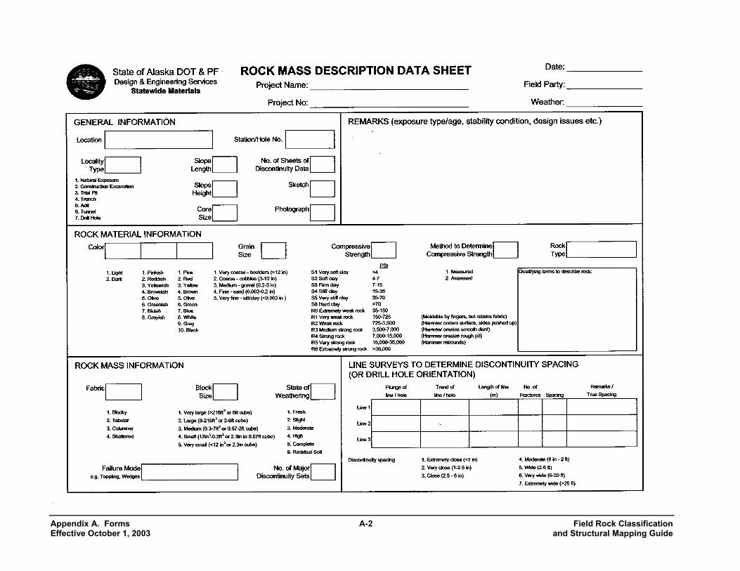
Appendix A. Forms The following forms are adapted from several sources, (principally Golder & Assoc.) and are based on the ISRM procedures. These forms provide a useful means of recording the mapping data outlined above and in the ISRM publications. The Rock Mass Description Data Sheet describes the rock in terms of its color, grain size and strength. The form provides for description of the rock mass in terms of its block shape and size, the state of weathering, and the number and spacing of discontinuity sets. The Rock Discontinuity Data Sheet is a form for describing the characteristics of discontinuities: type, orientation, persistence, aperture and width, fillings, surface roughness, and water conditions.
Field Rock Classification A-1 Appendix A. Forms And Structural Mapping Guide Effective October 1, 2003
Appendix A. Forms A-2 Field Rock Classification Effective October 1, 2003 and Structural Mapping Guide
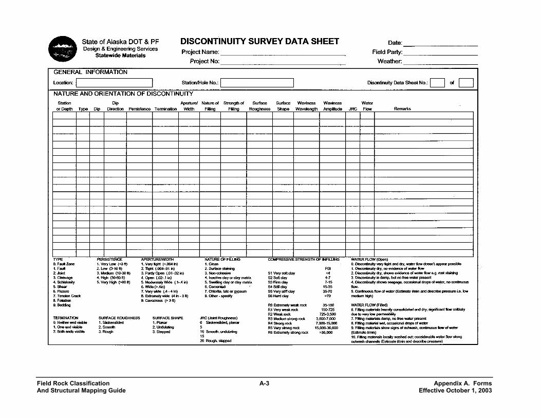
Field Rock Classification A-3 Appendix A. Forms And Structural Mapping Guide Effective October 1, 2003


