13
Alfra Rotabest Junior 75/50 Metal Core Drilling Machine Operation Manual 06/2003

Alfra Rotabest Junior 75/50 Metal Core Drilling Machine
Operation Manual
06/2003
2
1. Technical Data Prod. – No.: 18640 Name : Rotabest Junior 75/50 Input: 1800 Watt No-Load rpm: 110/175/245/385 rpm Tool Holder : MT 3 Coolant supply: internal, automatically Voltage: (see nameplate) Magnetic Adhesion: 20000 N Boring Ø max. in Steel: - Core Cutter 75 mm - Twist Drills 32 mm Cutting Depth: 50 mm Stroke: 190 mm Size of Magnet Foot: 80 x 230 mm

3
2. Description
a) Motor
b) Spindle c) Control Panel d) Magnet Foot e) Arbor f) Depth Scale
g) Hexagon screw for the adjustment of the motors´ stroke range
h) Clamping lever for clamping the magnet foot i) Recess for safety belt j) Adjusting screws for adjusting the slide

4
3. Standard scope of supply
a) Transport Case b) Coolant Unit
c) Coolant Spray
d) Chip Remover
e) Safety Belt
f) Allan Key 2,5 mm
g) Allan Key 6,0 mm
h) Toolholder AMK 3
Prior to use:
Read Operation Manual!
Pay attention to Safety Precautions! Appropriate Use
This device is destined to: Cut material with magnetizable surface with core cutters, twist drills and to tap threads in sheltered environment for commercial use industry and craft. The device is suitable for drilling vertical, horizontal and overhead.

5
4. Safety Precautions Danger of Injuries During drilling operations on walls and ceilings, the Metal Core Drilling Machine must be safeguarded with the included safety belt (f). The magnetic adhesion is not maintained in case of a failure of circuit. The cut core will be ejected automatically by the ejector pin. Danger of accident! The ejector pin could possibly break in case of improper use. Only use undamaged power cord and extension cords and regularly check on damages! Power supply and voltage details at the device must correspond. Personal protection equipment When working with this device, wear the following protection equipment: Safety goggles, appropriate footwear, ear protection, hair net (for long hair), possibly also apron and safety helmet.
5. Precautions of use
The place of installation for the magnet foot must be clean and rustfree. Remove lacquer- and filler. For non-magnetizable materials, please use the Rotabest Vacubest (Prod.-No. 18150). Do not execute any electric welding on the workpiece, on which the Metal Core Drilling Machine is used. Prior to all operations, mount coolant unit (b). Danger of injuries! Danger of an electric shock For operations on walls and ceilings, we recommend cooling with our spray (Alfra BIO 2000, Prod.- No. 21010).

6
Switching on and off.
�� Check connecting line and plug on damages first!
�� Push button MAGNET ON, in order to initiate the magnet and the
magnetic adhesion is guaranteed.
�� When working on walls and ceilings, safe machine with safety belt (f).
�� Push the button MOTOR ON to start the Motor. �� The magnet foot now reaches its maximum magnetic adhesion! In case
of a damaged magnet, the motor won´t start. �� To switch off machine proceed in reverse order : MOTOR OFF and
then MAGNET OFF! Change of tools
How to work with annular cutters ( Weldon shank)
�� Mount Tool Holder AMK 3 in arbor. �� Push ejector pin (center pin) through head of annular cutter.
�� Mounting of Rotabest Cutter according to drawing. Setscrew must be
positioned in the center of the lateral flat side of the Weldon shank. Fix tightly.
7
How to work with twist drills.
�� The drill chuck 3-16 mm with MT 3 shank is only to be used with twist drills.
�� Insert drill chuck with adaptor in the arbor.
�� Insert twist drill in drill chuck and tighten drill chuck key.
�� Twist drills with MT 3 shank can be inserted directly into the arbor.
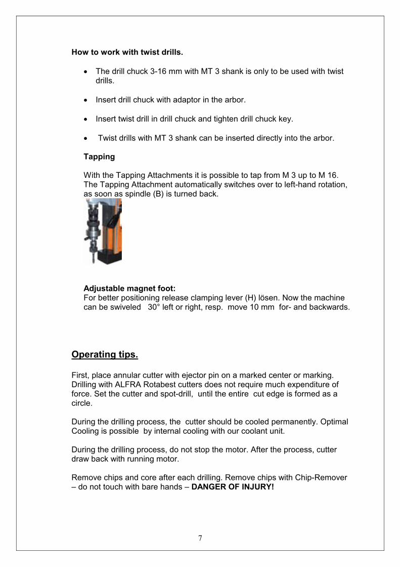
Tapping With the Tapping Attachments it is possible to tap from M 3 up to M 16. The Tapping Attachment automatically switches over to left-hand rotation, as soon as spindle (B) is turned back.
Adjustable magnet foot: For better positioning release clamping lever (H) lösen. Now the machine can be swiveled 30° left or right, resp. move 10 mm for- and backwards.
Operating tips. First, place annular cutter with ejector pin on a marked center or marking. Drilling with ALFRA Rotabest cutters does not require much expenditure of force. Set the cutter and spot-drill, until the entire cut edge is formed as a circle. During the drilling process, the cutter should be cooled permanently. Optimal Cooling is possible by internal cooling with our coolant unit. During the drilling process, do not stop the motor. After the process, cutter draw back with running motor. Remove chips and core after each drilling. Remove chips with Chip-Remover – do not touch with bare hands – DANGER OF INJURY!
8
6. Cleaning. Danger of injuries by unintentional switching on. Pull plug prior to cleaning. Clean motor by means of dry compressed air ( from the outside). Check connecting lines on damages. Clean and grease sliding surfaces regularly. Should, nevertheless, lateral play arise by wear of the dovetail guide, this could be adjusted by adjusting the laterally positioned set screws (K). Carbon brushes should be replaced after appr. 250 hours running time. After the work is finished, we recommend to store the Metal Core Drilling Machine in the transport case in a lying position.
7. Maintenance and repair. Maintenance, check and repairs are only to be made by electronics specialists according to the valid regulations of the respective country. The Metal Core Drilling Machine ALFRA ROTABEST should be serviced after appr. 250 hours running time by our Alfra workshop or appointed dealers. Only use genuine ALFRA spare parts. Spare part list at the end of this operation manual.
8. Accessories
Alfra Rota Quick HSS Co EcoCore Cutter Ø 12 – 50 mm Cutting depth 25 mm Product -No. 1901 0.. 025
Center- and ejector pin Product –No. 1926500
Alfra Rota Quick HSS Co Core Cutter Ø 12 – 50 mm Cutting depth 50 mm Product -No. 1901 0.. 050
Center- and ejector pin Product –No. 1950500
Alfra Rota Quick TCT Core Cutter Ø 18 – 35 mm Cutting Depth 35 mm Product -No. 2003 0.. 035
Center- and ejector pin Product –No. 2001500

9
Alfra Rota Quick TCT Core Cutter Ø 18 – 50 mm Cutting Depth 50 mm Product -No. 2003 0.. 050
Center- and ejector pin Product –No. 2001501
Alfra Tapping Attachment M3 – M12 Product-No. 18652 Alfra Tapping Attachment M10 – M 20 Product-No. 18653
HSS Countersink and Deburrer Ø 25 mm Product -No. 18533 HSS Countersink and Deburrer Ø 40 mm Product -No. 18534
Key Type Drill Chuck Ø 3-16 mm MT 3 Product -No. 18009
Attachment for clamping pipes Product -No. 18019
Vacuum device Vacubest Product -No. 18150
Coolant unit Product -No. 18104
Pressure Pump for coolant (5 Liter) Product -No. 20301
Alfra Bio 2000 Cutting Oil Product -No. 21010
Alfra Magnetic Chip Remover Product -No. 18654

10
Guarantee For our ALFRA Rotabest Metal Core Drilling Machines we grant guarantee according to the legal and regional regulations (proven by invoice).
9. CE Declaration of Conformity We declare in our exclusive responsibility, that this product correspond to the following standards and specifications:
Specification 89/392/EWG, 91/368/EWG DIN EN 292 part 1 and 2 DIN EN 60204 part 1 DIN VDE 0740 T The proof of an electromagnetic amicability took place according the appropriate EC-Specification 89/336/EWG after the following norms: EN 61000-3-2:1995/A1:1998/A2:1998 EN 61000-3-3:1995 EN 55014-1:1993/ A1:1997 55014-2:1997 If the electric tool is modified without our authorization, this declaration will lose ist validity and the guarantee expires. The sound pressure level at the work place might exceed 85 dp(A). In case the user must wear hearing protectors.

11
10. Spare Parts
Pos. N° Pce
1 189501070 1
2 189501071 1
3 189601114 1
5 189501072 1
6 189501073 1
7 189501060 3
8 189501074 2
9 189480005 1
10 189501076 2
11 189601101 1
12 189501078 1
14 189480001 1
15 189301079 1
16 189501084 1
17 189120410 1
18 189090410 5
19 189040510 4
20 189020512 15
21 189040516 1
22 189200420 2
23 189010620 6
24 189010880 2
26 189185516 4
27 189100019 1
28 189112535 1
29 189490503 2
30 189301080 1
31 189041210 3
33 189601096 5
34 189480276 1
35 189490604 1
36 189490605 2
37 189601102 1
39 189480009 1
40 189172050 8
41 189160416 4
42 189491010 1
43 189411080 * 1
44 189601112 1
45 18104 1
46 18035 * 1
48 189060005 3
49 189060006 6
50 189060012 1
52 189490606 1
53 189490607 1
55 189480020 1
56 189480021 1
65 189411027 * 1
66 189601105 1
67 189601109 1
68 189601110 1
70 189601107 1
71 189601108 2
73 189601106 1
74 189601113 1 * Bitte die Spannung angeben
12
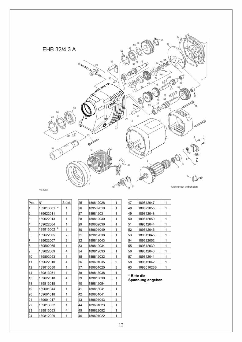
Pos. N° Stück 1 189813001 * 1 2 189622011 1 3 189622013 1 4 189622004 1 5 189813002 * 1 6 189622005 2 7 189622007 2 8 189502065 1 9 189622009 4 10 189802053 1 11 189622010 4 12 189813050 1 14 189813051 1 15 189622018 4 18 189813018 1 19 189601044 1 20 189601018 1 21 189601017 1 22 189813052 1 23 189813053 4 24 189812029 1
25 189812028 1 26 189502019 1 27 189812031 1 28 189812030 1 29 189602036 1 30 189601049 1 31 189812038 1 32 189812043 1 33 189812034 1 34 189812033 1 35 189812032 1 36 189601035 2 37 189601020 3 38 189813038 1 39 189813039 1 40 189812054 1 41 189813041 1 42 189601041 1 43 189601043 4 44 189601023 1 45 189622052 1 46 189601022 1
47 189812047 1 48 189622055 1 49 189812048 1 50 189812050 1 51 189812044 1 52 189812046 1 53 189812045 1 54 189622052 1 55 189812039 1 56 189812040 1 57 189812041 1 58 189812042 1 63 189601023B 1 * Bitte die Spannung angeben
13
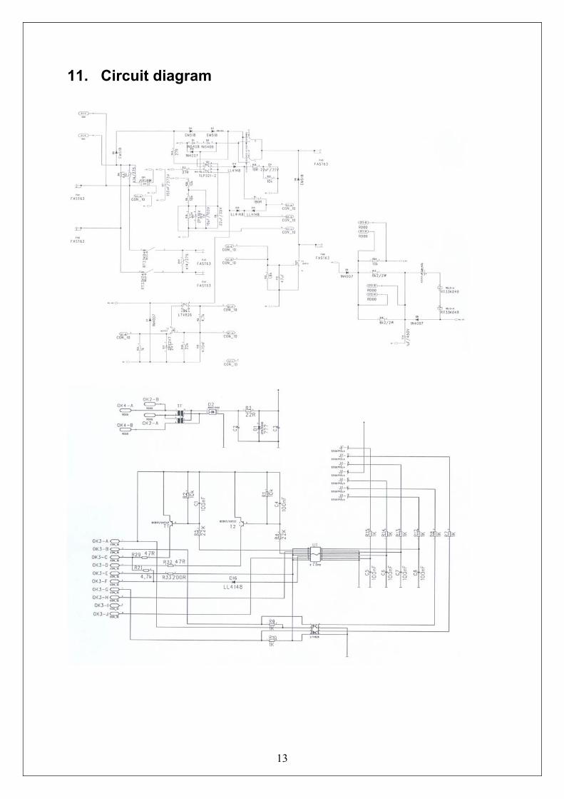
11. Circuit diagram


