This thesis describes extensions to state machines in the Umple model-‐oriented
programming language to offer queued state machines (QSM), pooled state machines
(PSM) and handing of the arrival of unexpected events. These features allow for
modeling the behavior of a system or protocol in a more accurate way in Umple
because they enable detecting and fixing common design errors such as unspecified
receptions. In addition, they simplify the communication between communicating state
machines by allowing for asynchronous calls of events and passing of messages
between state machines. Also, a pooled state machine (PSM) has been developed to
provide a different policy of handling events that avoid unspecified receptions. This
mechanism has similar semantics as a queued state machine, but it differs in the way of
detecting unspecified receptions because it helps handling these errors. Another
mechanism has been designed to use the keyword ‘unspecified’ in whatever state of a
state machine the user wants to detect these errors. In this thesis, the test-‐driven
development (TDD) process has been followed to first modify the Umple syntax to add
‘queued,’ ‘pooled,’ and ‘unspecified’ keywords to Umple state machine’s grammar; and
second, to make a change to the Umple semantics in order to implement these
extensions in Umple. Then, additional modifications have been made to allow for Java
code generation from those types of state machines. Finally, more test cases have been
written to ensure that these models are syntactically and semantically correct. In order
to show the usefulness and usability of these new features, an example is shown as a
case study that is modeled using the queued state machine (QSM) besides other small
tests cases.
iii
Acknowledgements
I would like to take this opportunity to thank Dr. Timothy C. Lethbridge, my co-‐
supervisor, for his support and assistance throughout this M.Sc. thesis, as well as Dr.
Gregor von Bochmann, my head supervisor. Thanks also to my research group,
Complexity Reduction Software Engineering (CRuiSE). Sincerest thanks to my father,
mother and siblings for their constant support, encouragement and understanding
during this endeavour. Finally, I am very thankful to my sponsor Al Baha University for
its financial support during the academic program.
iv
Table of Contents Abstract ............................................................................................................................................. ii
Acknowledgements ..................................................................................................................... iii
List of Figures ................................................................................................................................. ix
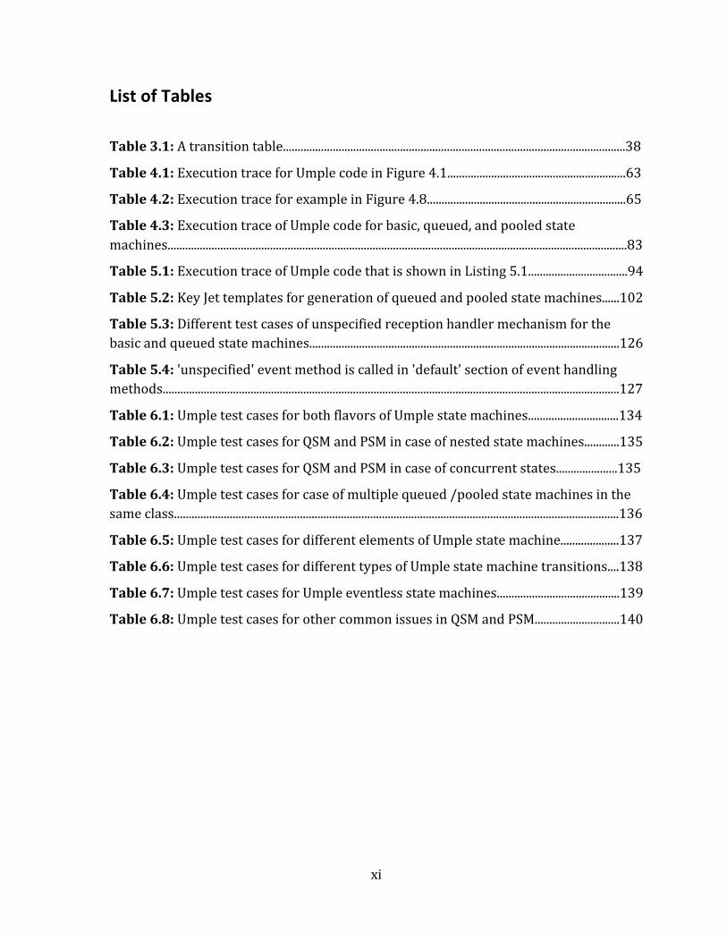
List of Tables .................................................................................................................................. xi
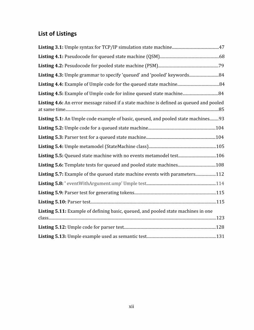
List of Listings .............................................................................................................................. xii
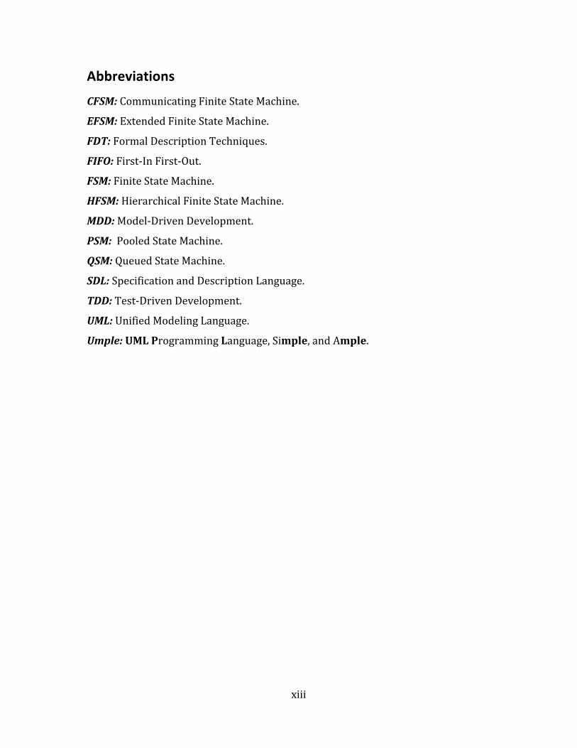
Abbreviations .............................................................................................................................. xiii
1.1 Goal of the Thesis ...................................................................................................................................................... 3
1.2 Research Questions .................................................................................................................................................. 4
Chapter 2 Umple: A Model-‐Oriented Programming Language ....................................... 6
2.1 Introduction to Umple ............................................................................................................................................. 6
2.2 Layered Architecture of Umple ........................................................................................................................... 7
2.3 Advantages of Using Umple .................................................................................................................................. 7
2.5 Umple Features and Properties ........................................................................................................................ 10
2.6.2 Umple as an Eclipse Plugin .............................................................................................................................. 15
2.8 Development of Umple .......................................................................................................................................... 18
2.8.1 Agile Development .............................................................................................................................................. 18
2.8.3 Model-‐Driven Development (MDD) Methodology ................................................................................ 20
2.8.3.1 Advantages of Model-‐Driven Development (MDD) .............................................................................................. 23
2.8.4 Test-‐Driven Development (TDD) Methodology ..................................................................................... 24
2.8.4.1 Benefits of Test-‐Driven Development (TDD) Methodology .............................................................................. 26
v
2.8.5 Benefits of Using a Combination of Agile, Continuous Integration (CI), and Test-‐Driven Development (TDD) Methodologies ....................................................................................................................... 27
2.9 Building the Umple System Using a Test-‐Driven Development (TDD) Strategy ......................... 27
2.9.2 Test-‐Driven Development Methodology (TDD) and Umple .............................................................. 29
Chapter 3 Literature Review ................................................................................................... 32
3.1 Protocols and Formal Description Techniques (FDTs) .......................................................................... 32
3.2 Finite State Machine (FSM) ................................................................................................................................. 34
3.2.1 Advantages of Finite State Machine (FSM) ............................................................................................... 35
3.2.2 Representation of Finite State Machine (FSM) ....................................................................................... 36
3.2.3 Extended Finite State Machine (EFSM) ...................................................................................................... 38
3.2.4 Hierarchal Finite State Machine (HFSM) ................................................................................................... 39
3.2.5 Communicating Finite State Machine (CFSM) ......................................................................................... 39 3.2.5.1 Communication Mechanisms For CFSM .................................................................................................................... 41
3.3 Specification and Description Language (SDL) .......................................................................................... 41
3.4 Unified Modeling Language (UML) .................................................................................................................. 42
3.5 Umple State Machine ............................................................................................................................................. 44
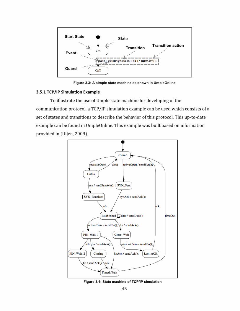
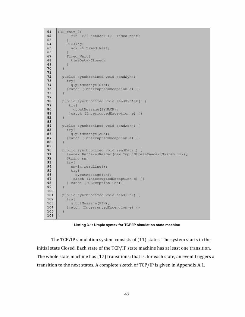
3.5.1 TCP/IP Simulation Example ............................................................................................................................ 45
3.5.2 Communicating Mechanisms For State Machines in Umple ............................................................. 48
3.6 Related Work ............................................................................................................................................................. 48
3.6.1 State Machine Compiler (SMC) ...................................................................................................................... 48
3.6.2 Sparx Systems Enterprise Architecture (EA) .......................................................................................... 52
3.6.3 Real-‐Time Developer Studio (RTDS) ........................................................................................................... 53
3.7 Handling Unspecified Reception in Specification Languages ............................................................... 54
3.7.1 Original Semantic of Umple State Machines in Case of Unspecified Reception ........................ 55
3.7.2 Save Operator in SDL and Deferred Event in UML ................................................................................ 55
Chapter 4: Queued State Machines (QSM) and Pooled State Machine (PSM) in Umple .............................................................................................................................................. 57
4.1 Enhancements to Umple State Machines ...................................................................................................... 57
4.2 Queued State Machine (QSM) in Umple ......................................................................................................... 66
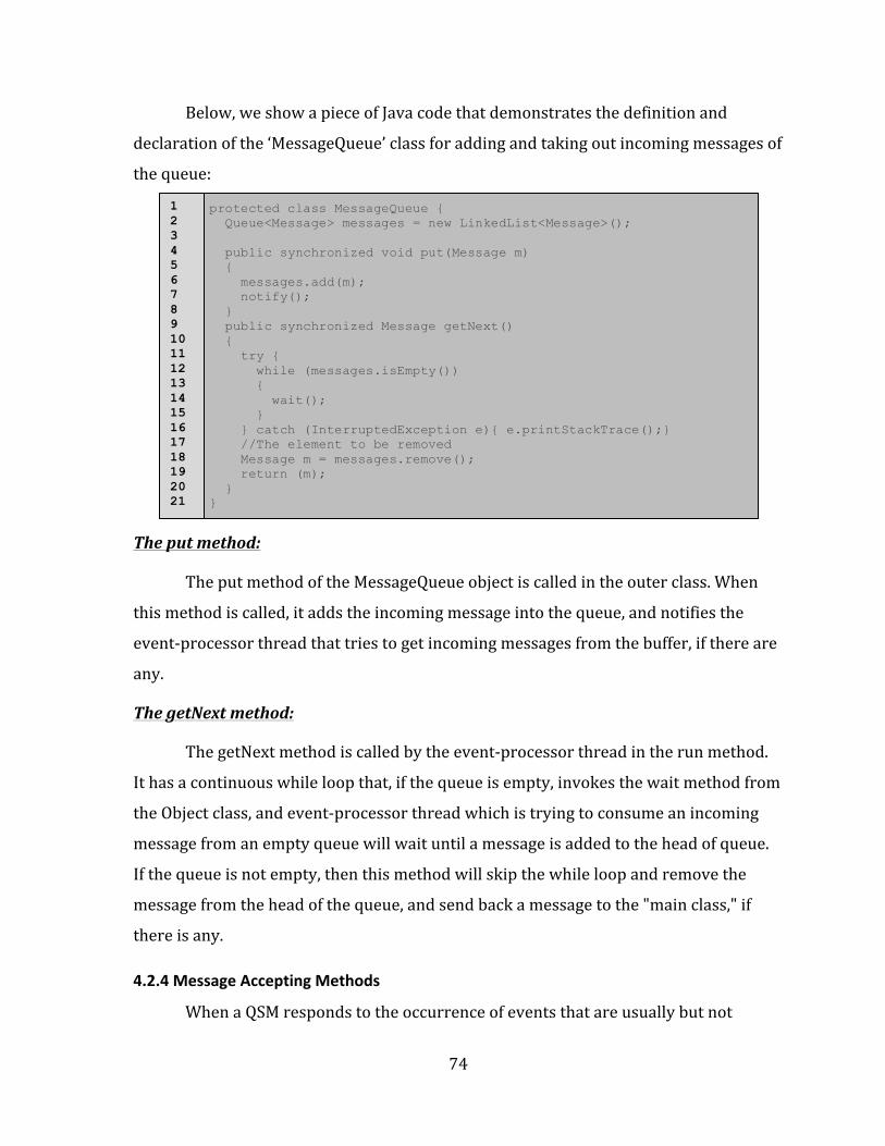
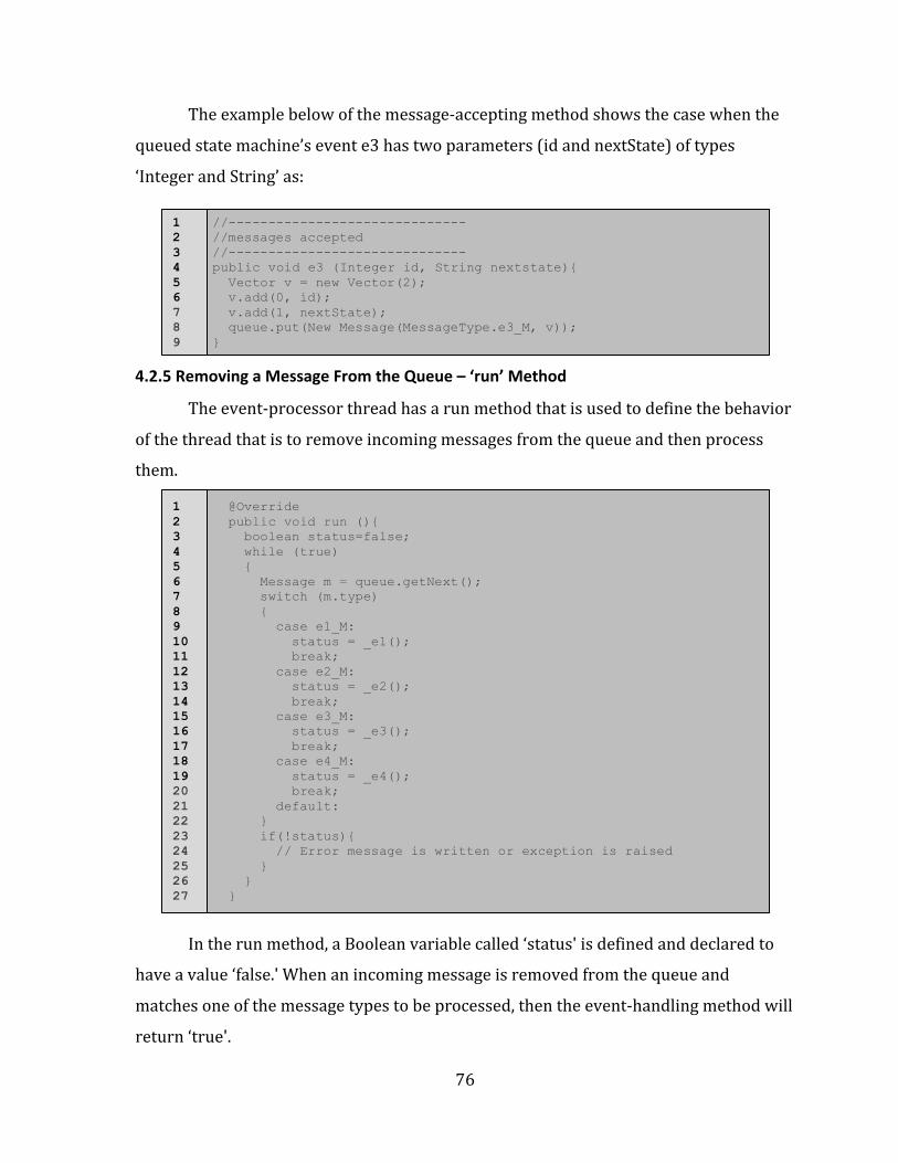
4.2.5 Removing a Message From the Queue – ‘run’ Method ........................................................................ 76
4.3 Pooled State Machine (PSM) in Umple ........................................................................................................... 77
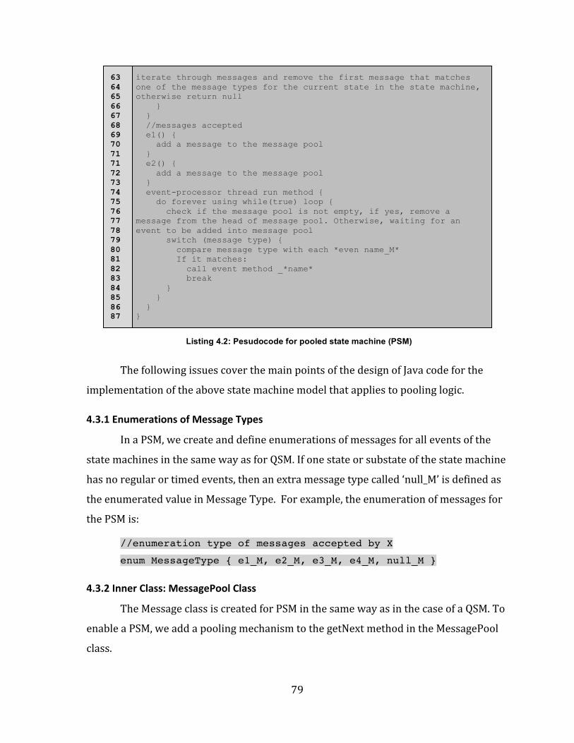
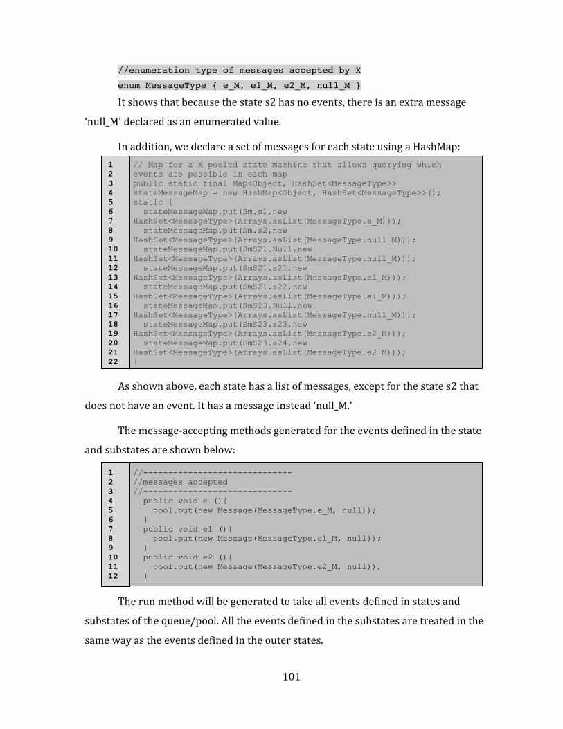
4.3.1 Enumerations of Message Types ................................................................................................................... 79
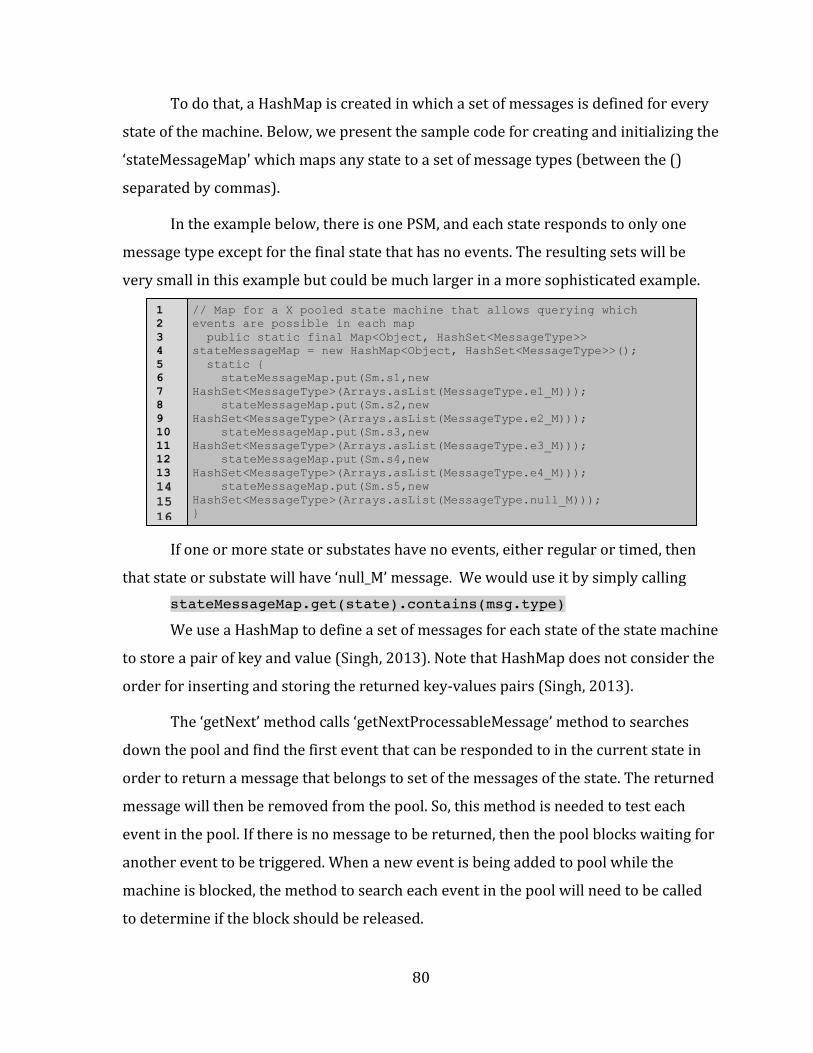
4.3.2 Inner Class: MessagePool Class ..................................................................................................................... 79
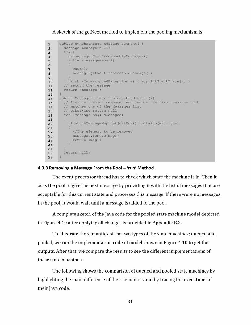
4.3.3 Removing a Message From the Pool – ‘run’ Method ............................................................................. 81
4.4 Syntax of Umple Queued State Machine (QSM) and Pooled State Machine (PSM) ..................... 83
4.4.1 Allowing For a Queued State Machine in Umple (QSM) ...................................................................... 83
4.4.2 Allowing for a Pooled State Machine in Umple (PSM) ......................................................................... 85
4.4.3 Writing Queued and Pooled Keywords on the Same Line to Define a State Machine in Umple ................................................................................................................................................................................... 85
4.5 Semantics of Umple Queued State Machine (QSM) and Pooled State Machine (PSM) .............. 85
4.6 Common Issues in Umple Queued State Machine (QSM) and Pooled State Machine (PSM) .. 87
4.6.1 Issue with Timed Transitions in Queued or Pooled State Machines ............................................. 87
4.6.2 Issue with Instantaneous Transitions in Queued or Pooled State Machine ............................... 91
Chapter 5 Implementation of Queued and Pooled State Machines ........................... 93
5.1 Goals For Code Generation .................................................................................................................................. 93
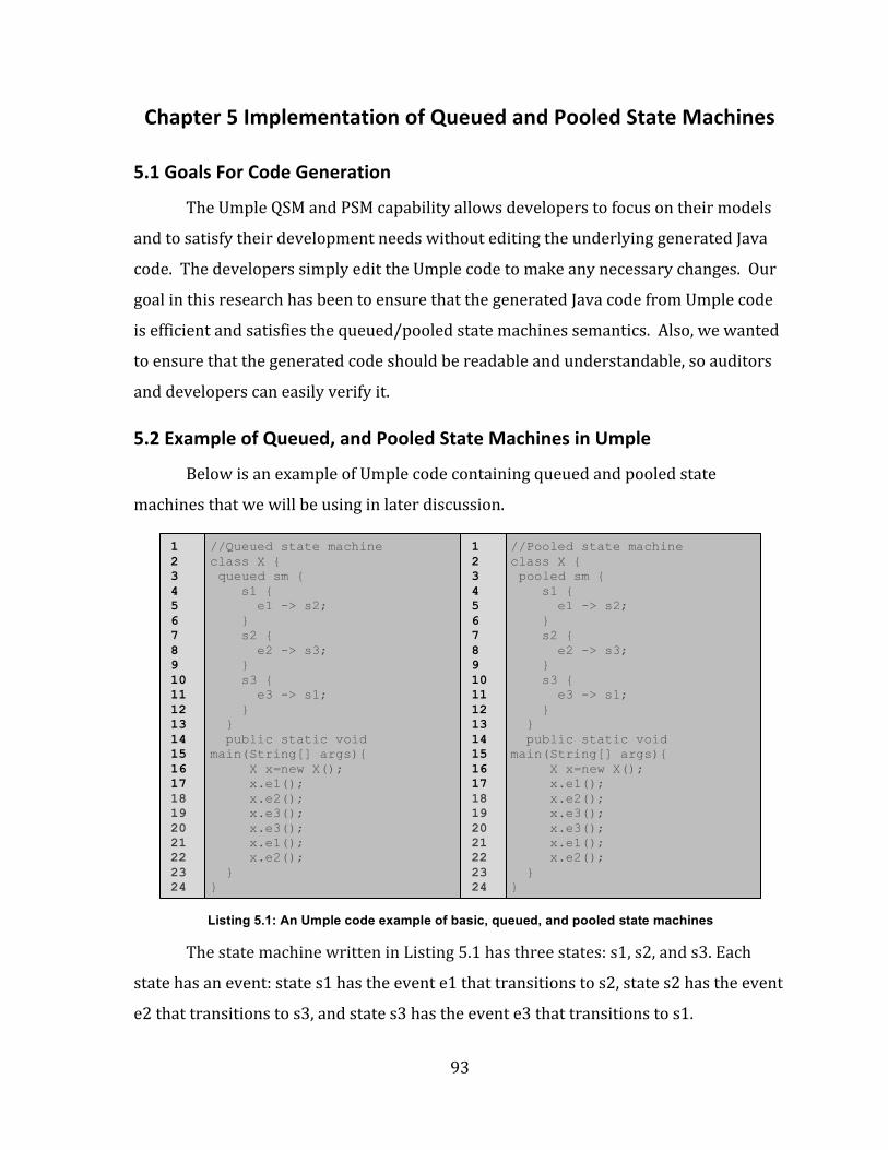
5.2 Example of Queued, and Pooled State Machines in Umple ................................................................... 93
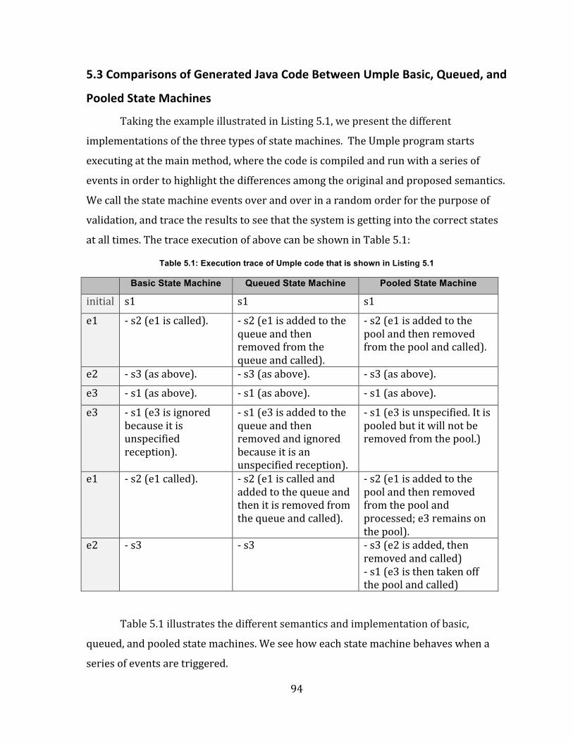
5.3 Comparisons of Generated Java Code Between Umple Basic, Queued, and Pooled State Machines ............................................................................................................................................................................. 94
5.4 Simple QSM and PSM in Umple ......................................................................................................................... 95
5.4.1 Examples of Simple QSM and PSM in Umple ........................................................................................... 95
5.4.1.1 Case Where State Machine Events Have No Arguments .................................................................................... 95 5.4.1.2 Case Where Some State Machine Events Have Arguments ............................................................................... 96
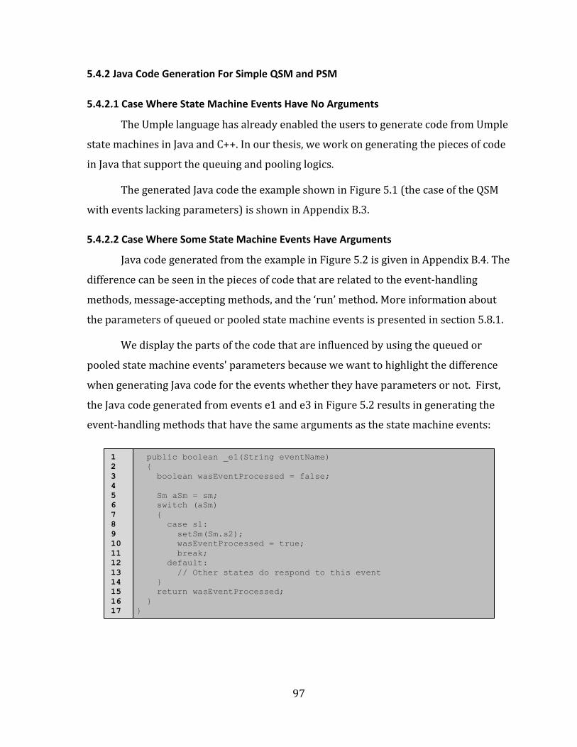
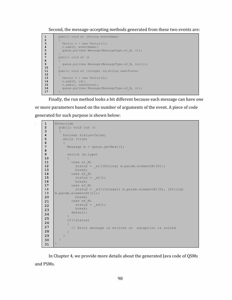
5.4.2 Java Code Generation For Simple QSM and PSM .................................................................................... 97 5.4.2.1 Case Where State Machine Events Have No Arguments .................................................................................... 97 5.4.2.2 Case Where Some State Machine Events Have Arguments ............................................................................... 97
5.5 Composite QSM and PSM in Umple ................................................................................................................. 99
5.5.1 Examples of Composite QSM and PSM in Umple ................................................................................... 99 5.5.1.1 Example of Umple QSM and PSM with Nested States .......................................................................................... 99 5.5.1.2 Example of Umple QSM and PSM with Concurrent States ............................................................................... 100
vii
5.5.2 Java Code Generated From Umple Composite QSM and PSM Examples .................................. 100
5.6 Code Generation Templates of Queued and Pooled State Machines .............................................. 102
5.7 Test-‐Driven Development of QSM and PSM in Umple .......................................................................... 103
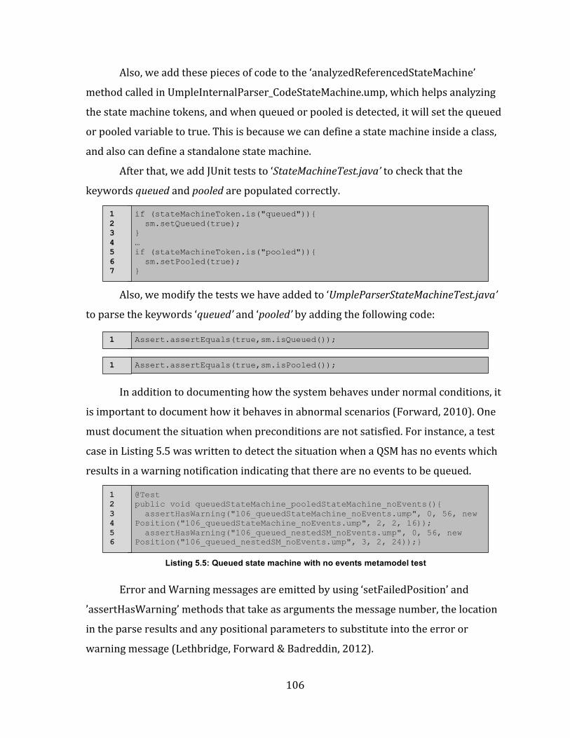
5.7.3 Template or Code Generation Testing ..................................................................................................... 107
5.7.4 Language-‐Oriented Semantic or Testbed Testing .............................................................................. 109
5.8 Various Issues Related to Java Code Generation of Simple and Composite QSM and PSM .. 111
5.8.1 Queued or Pooled State Machine’s Events with Arguments .......................................................... 111
5.8.2 Timed Transitions in QSM and PSM ......................................................................................................... 116
5.8.3 Single Event Causing Multiple Transitions in Nested or Concurrent States of Queued or Pooled State Machines ............................................................................................................................................... 118
5.8.4 Single Event Causing Multiple Transitions in Multiple Queued or Pooled State Machines in the Same Class ............................................................................................................................................................... 118
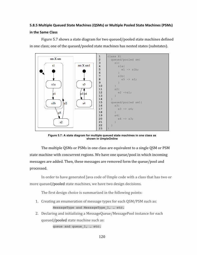
5.8.5 Multiple Queued State Machines (QSMs) or Multiple Pooled State Machines (PSMs) in the Same Class ....................................................................................................................................................................... 120
5.8.6 One or More (QSMs) with One or More Basic and/or (PSMs) in the Same Class ................. 122
5.8.7 QSM or PSM with at Least One State But with No Events (Raising a Warning Message) .. 123
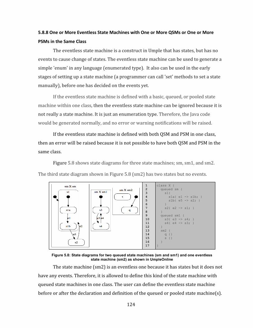
5.8.8 One or More Eventless State Machines with One or More QSMs or One or More PSMs in the Same Class ....................................................................................................................................................................... 124
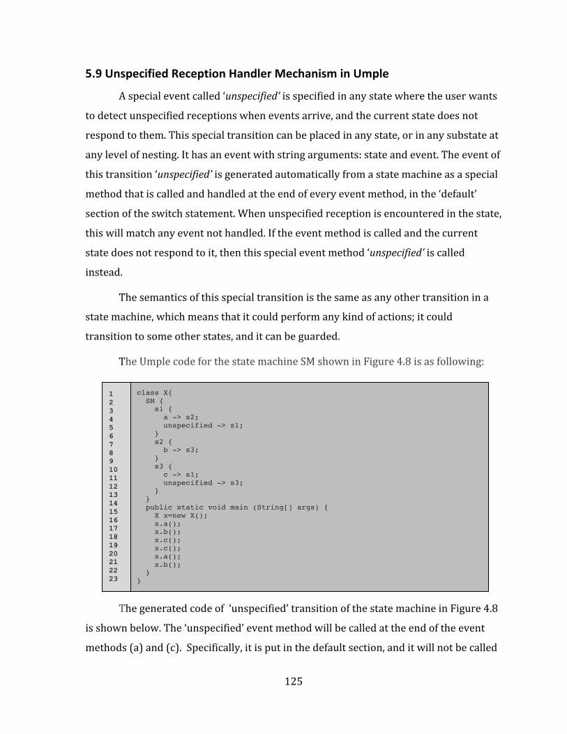
5.9 Unspecified Reception Handler Mechanism in Umple ......................................................................... 125
5.9.1 Test-‐Driven Development (TDD) For Adopting the Unspecified Reception Handler Mechanism in Umple .................................................................................................................................................. 128
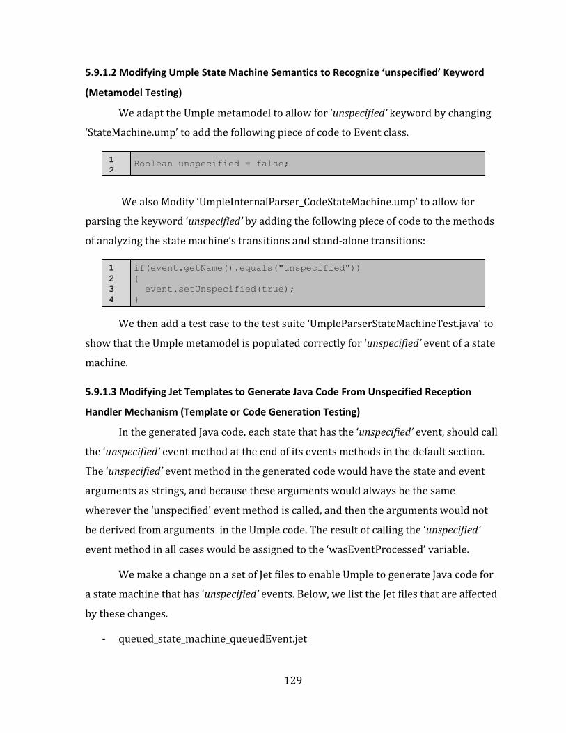
5.9.1.1 Modifying Umple State Machine Grammar to Have ‘unspecified’ Keyword as a Special Event in a State Machine (Parser Testing) .................................................................................................................................................. 128 5.9.1.2 Modifying Umple State Machine Semantics to Recognize ‘unspecified’ Keyword (Metamodel Testing) ................................................................................................................................................................................................. 129 5.9.1.3 Modifying Jet Templates to Generate Java Code From Unspecified Reception Handler Mechanism (Template or Code Generation Testing) ................................................................................................................................. 129 5.9.1.4 Adding Semantic Tests For Java Code Generation of Unspecified Reception Handler Mechanism (Semantic Testing) ........................................................................................................................................................................... 130
Chapter 6 Test Cases and a Real-‐Time Case Study ......................................................... 133
6.1 Test Cases For Different Features and Issues of Queued and Pooled State Machines ........... 133
6.1.1 Tests For Different Types of Umple State Machines .......................................................................... 134
viii
6.1.2 Nested State Machines .................................................................................................................................... 135
6.1.3 Concurrent States ............................................................................................................................................. 135
6.1.4 Tests For Multiple State Machines in the Same Class ....................................................................... 136
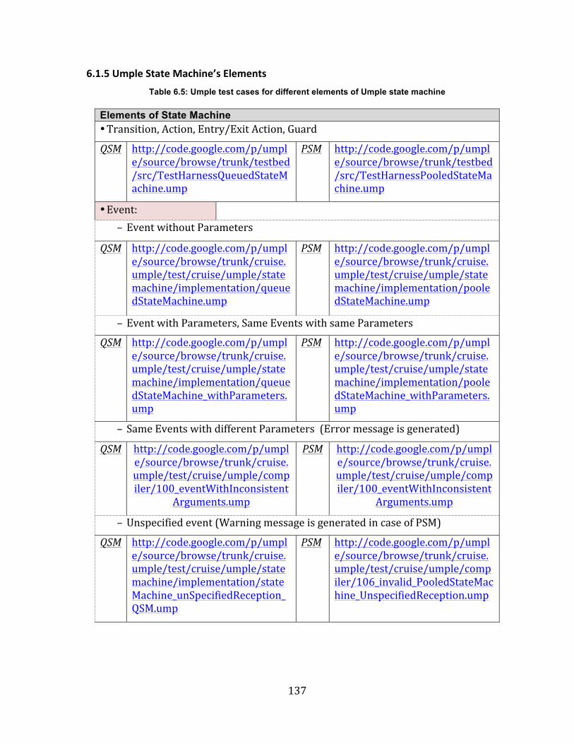
6.1.5 Umple State Machine’s Elements ............................................................................................................... 137
6.1.6 Umple State Machine Transitions .............................................................................................................. 138
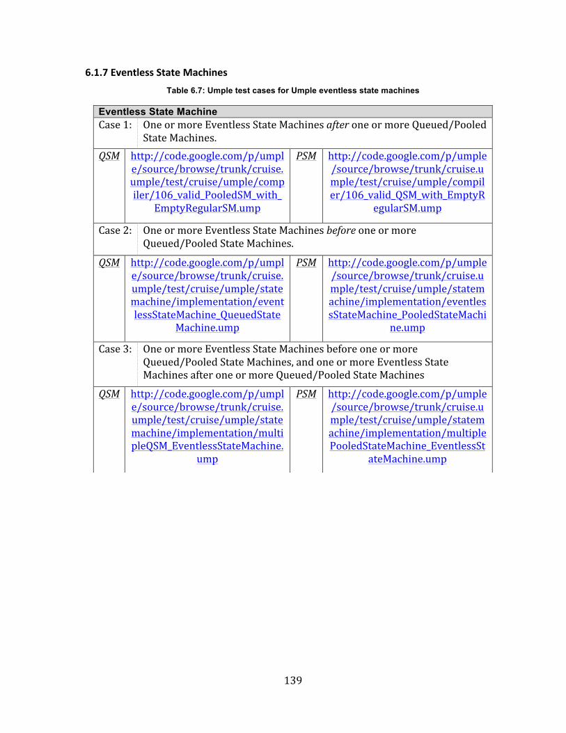
6.1.7 Eventless State Machines .............................................................................................................................. 139
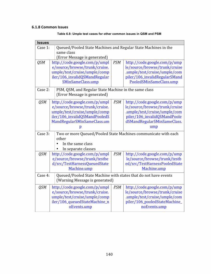
6.1.8 Common Issues .................................................................................................................................................. 140
6.2 Evaluation of Umple Queued State Machines (QSM)– Case Study .................................................. 141
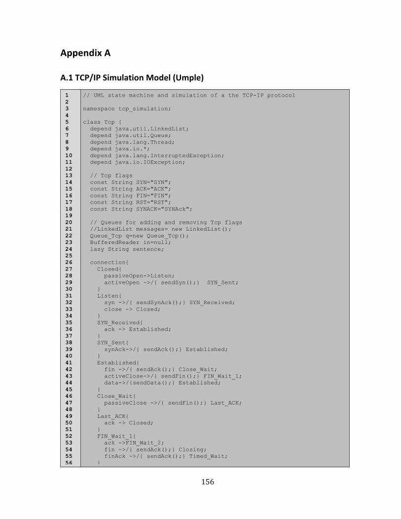
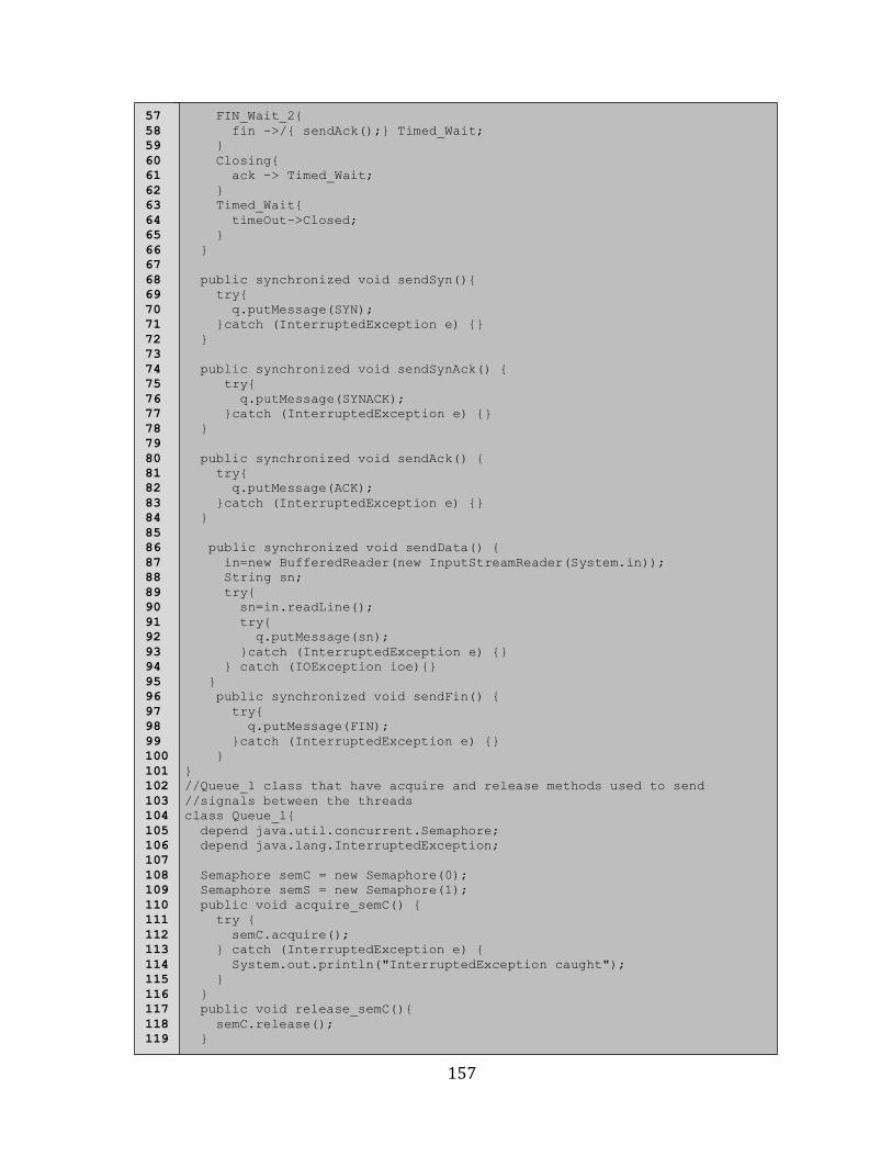
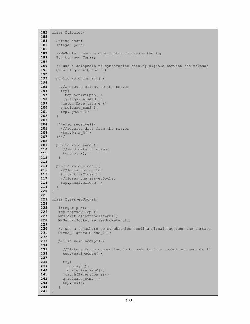
Appendix A .................................................................................................................................. 156
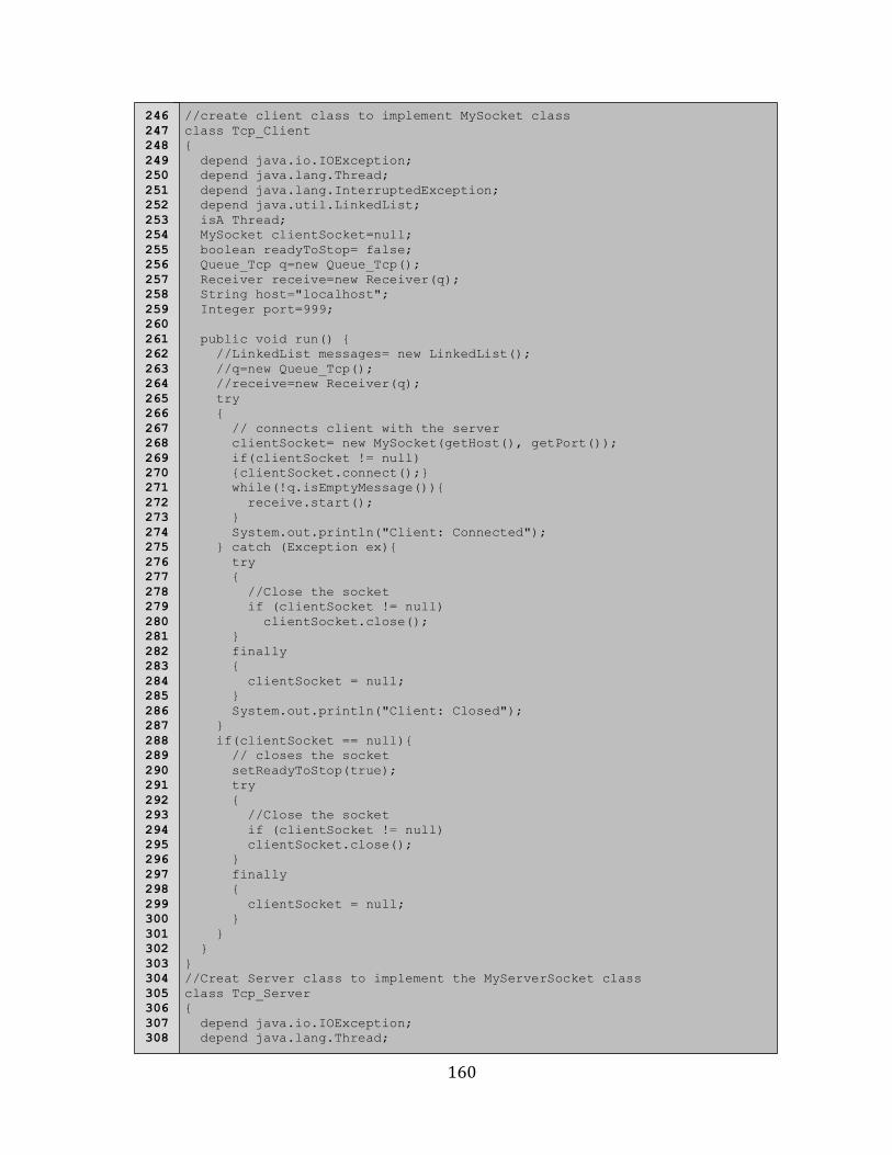
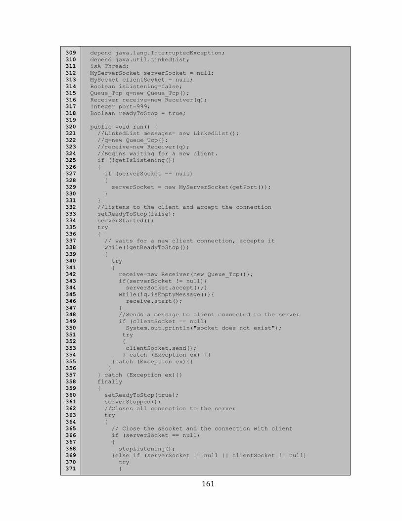
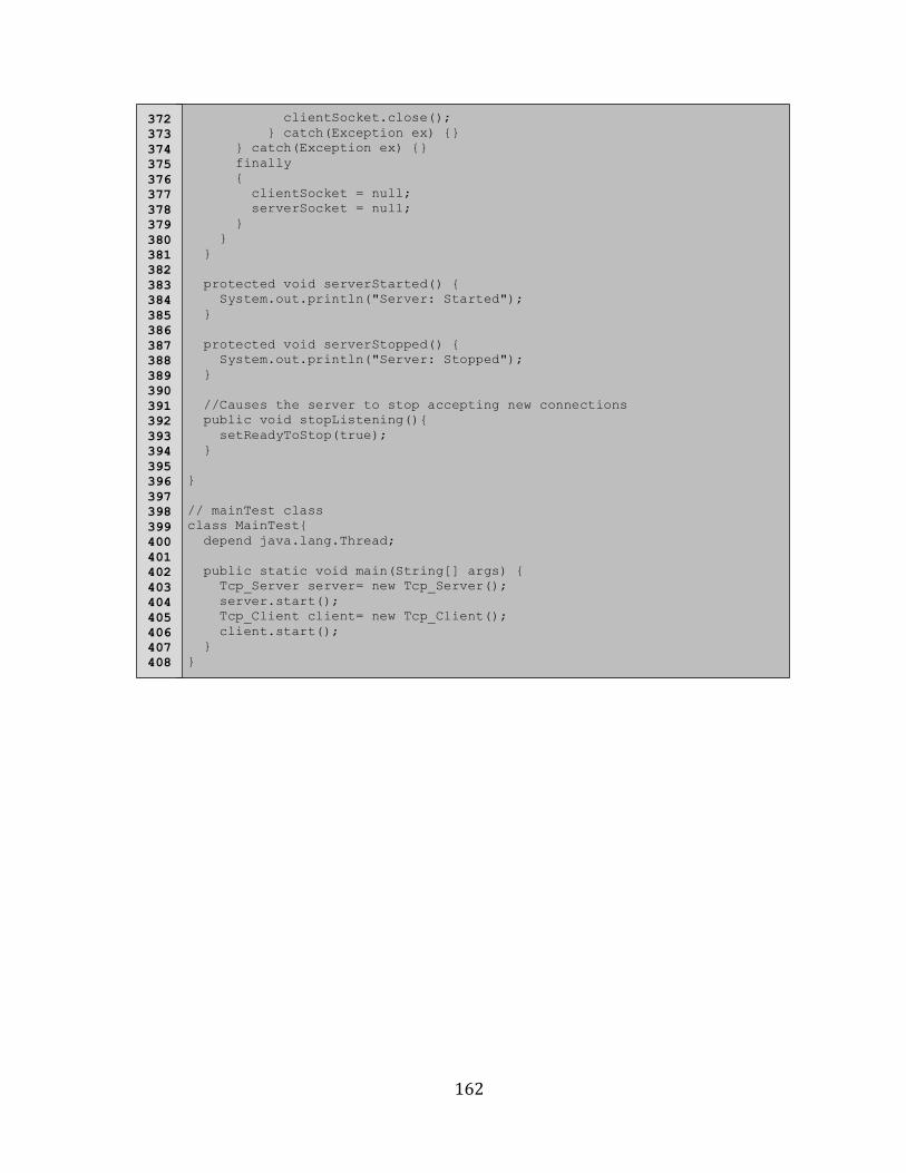
A.1 TCP/IP Simulation Model (Umple) ............................................................................................................... 156
Appendix B .................................................................................................................................. 163
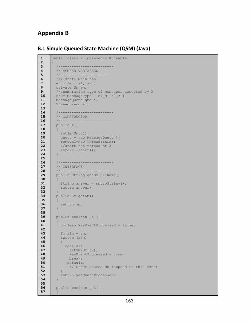
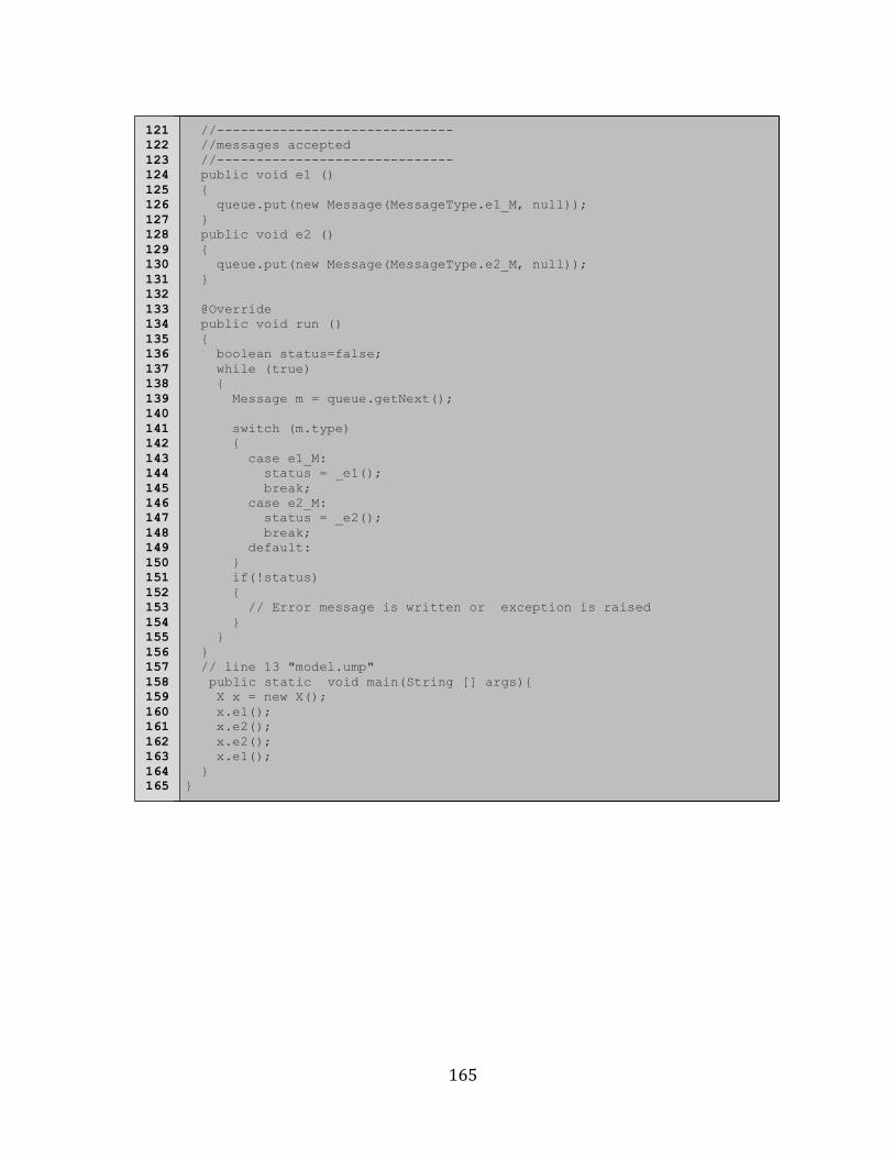
B.1 Simple Queued State Machine (QSM) (Java) ............................................................................................ 163
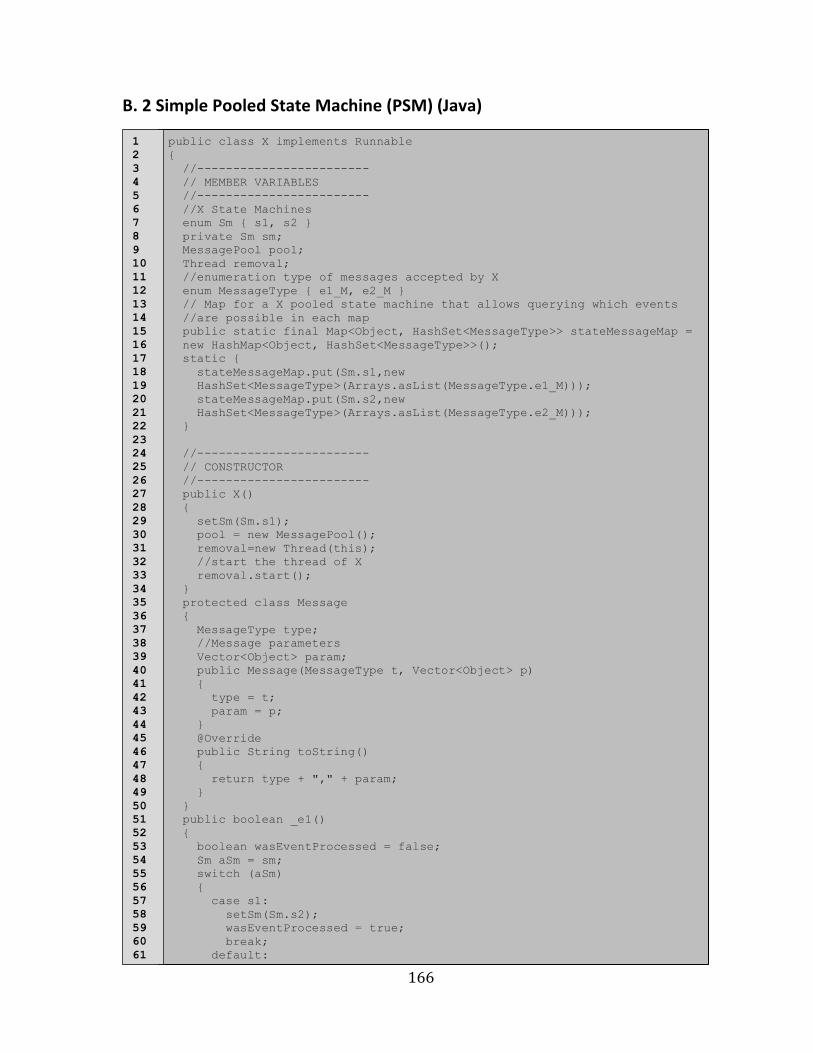
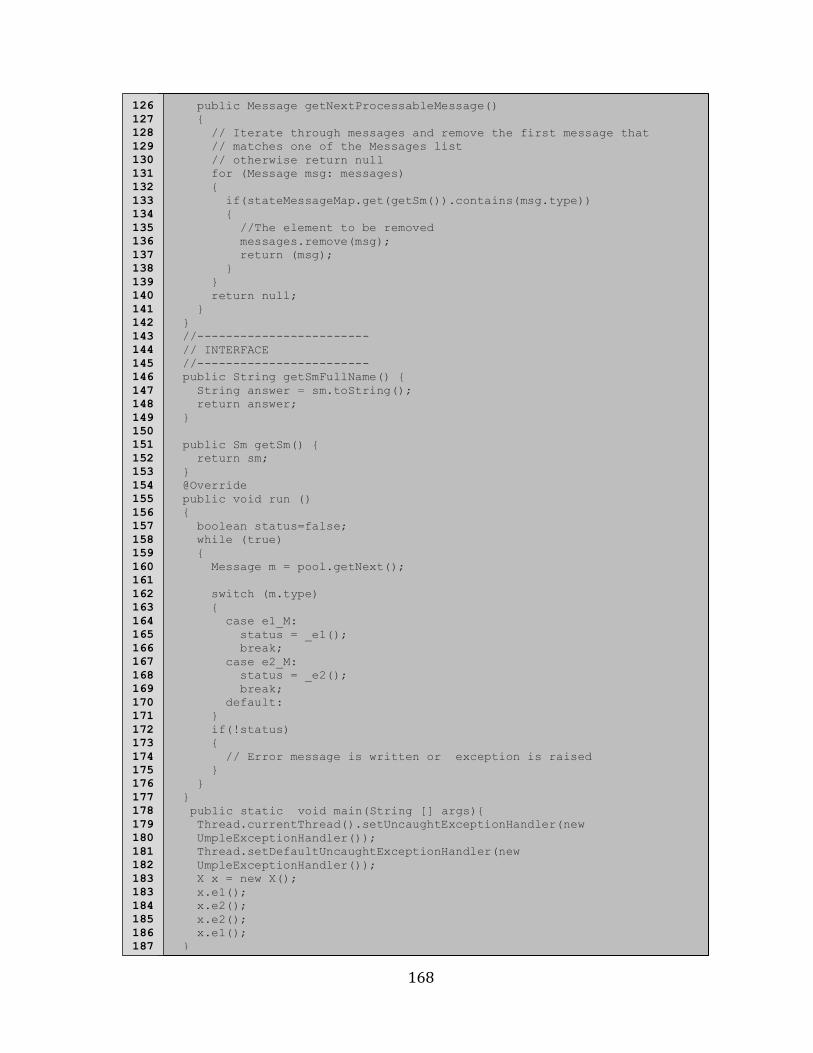
B. 2 Simple Pooled State Machine (PSM) (Java) ............................................................................................. 166
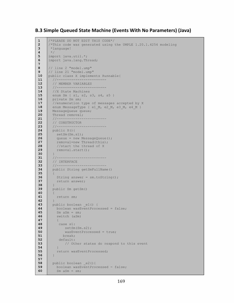
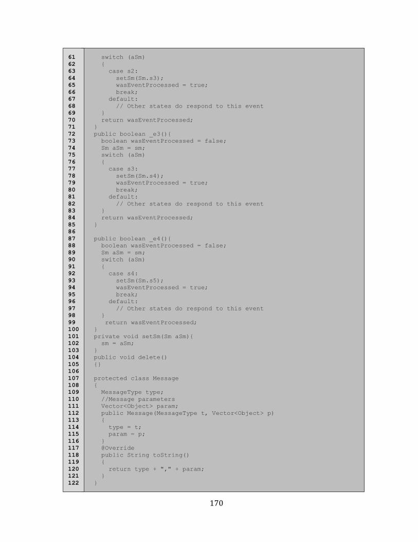
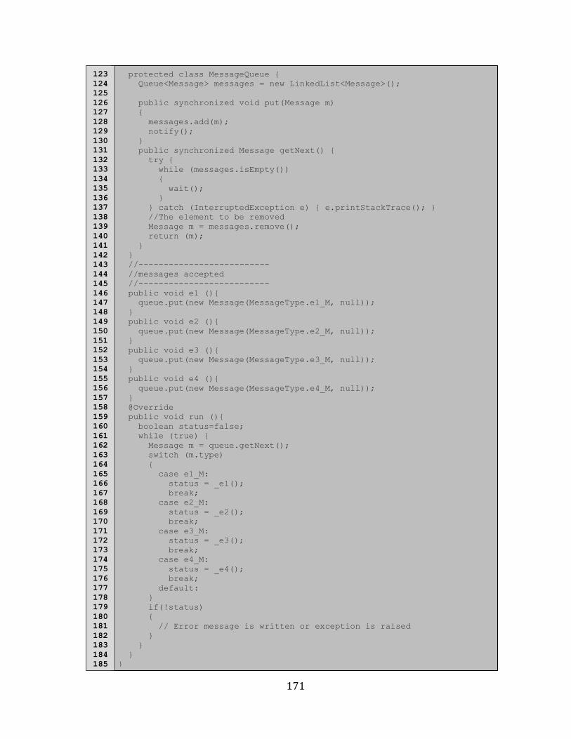
B.3 Simple Queued State Machine (Events With No Parameters) (Java) ............................................ 169
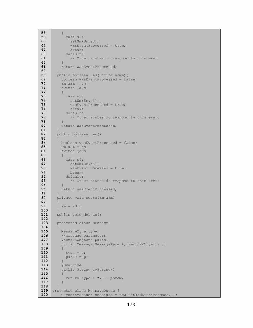
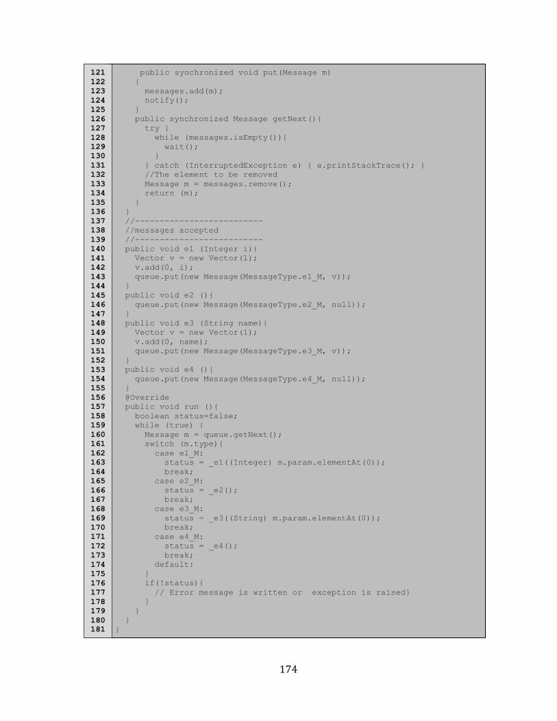
B.4 Simple Queued State Machine (Events With Parameters) (Java) ................................................... 172
Appendix C .................................................................................................................................. 175
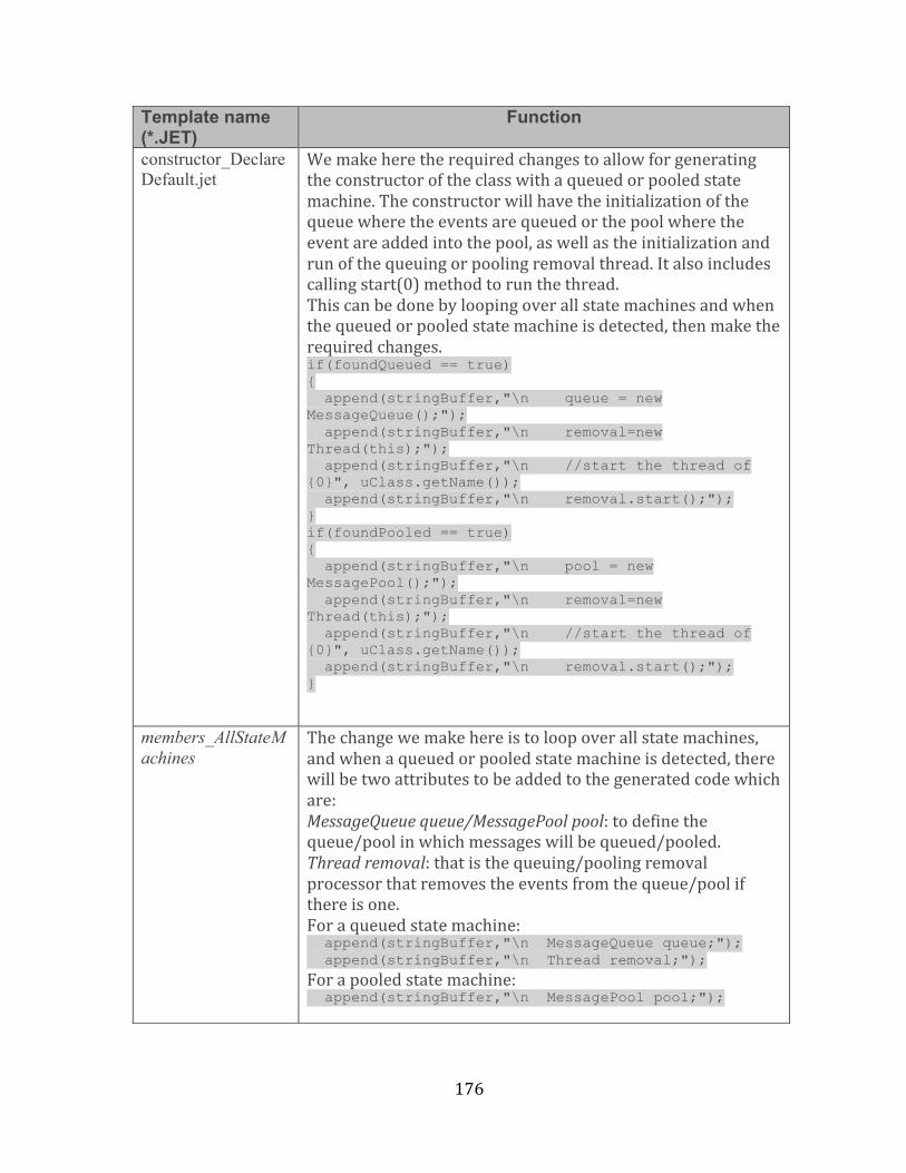
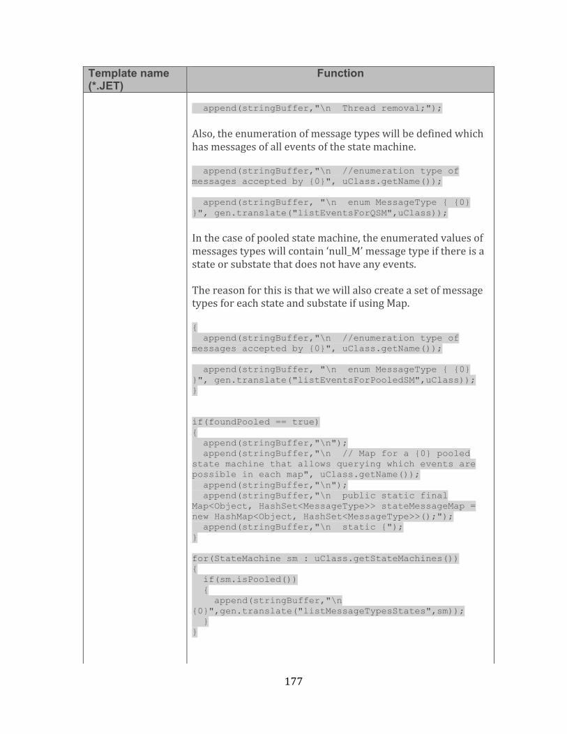
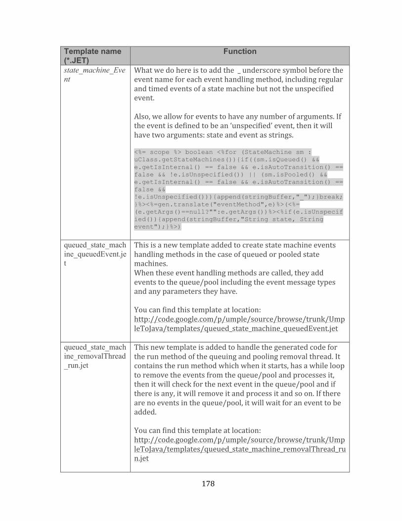
C.1 Key Code Generation Jet Templates Files For QSM and PSM ............................................................ 175
Appendix D .................................................................................................................................. 180
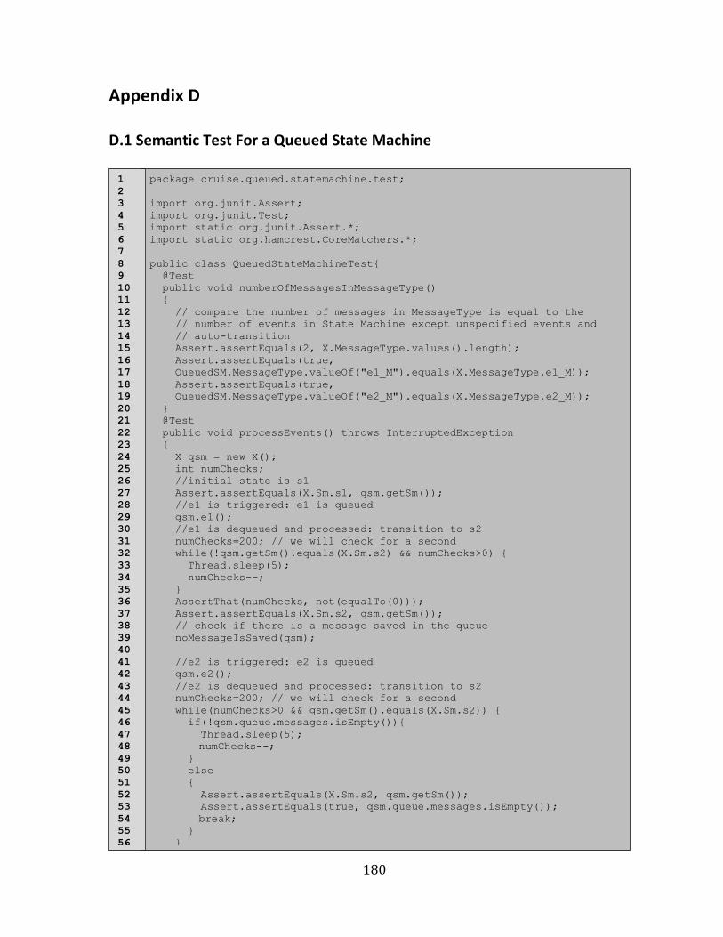
D.1 Semantic Test For a Queued State Machine ............................................................................................. 180
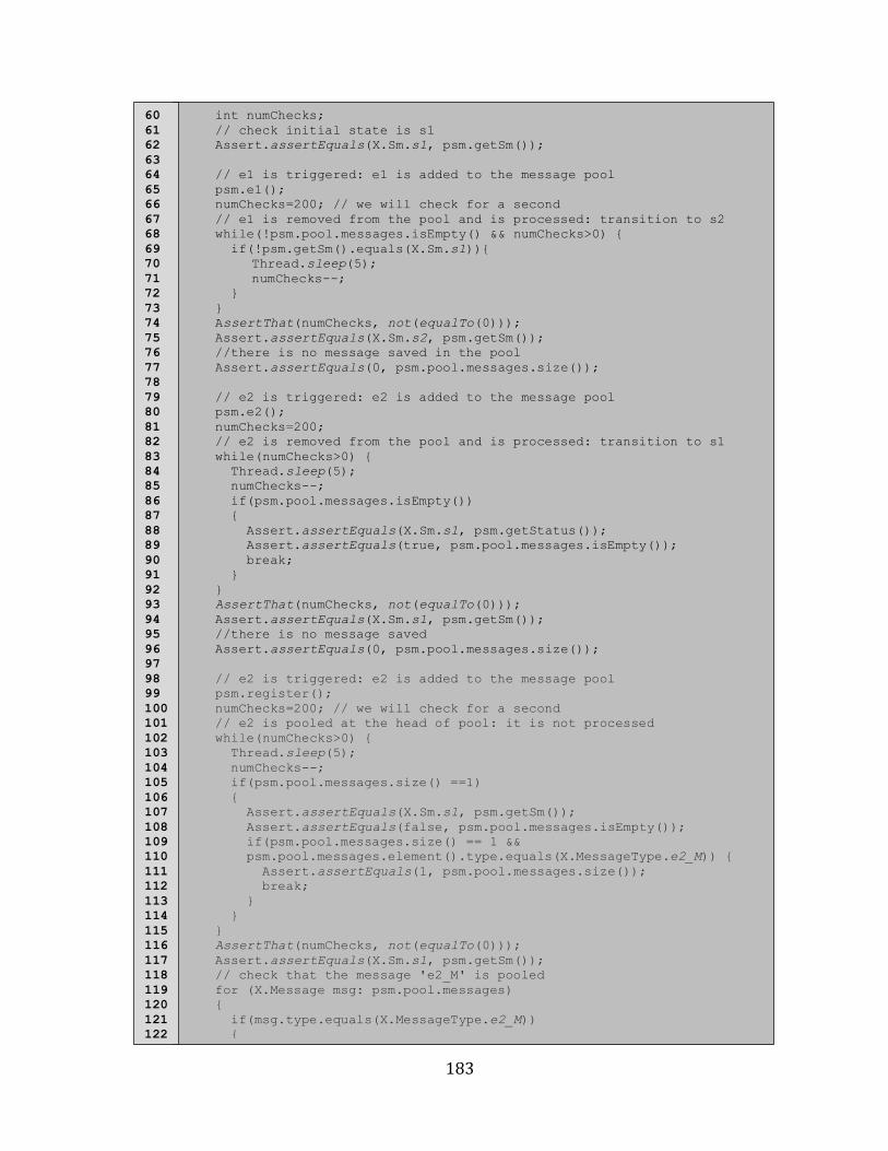
D.2 Semantic Test For a Pooled State Machine ............................................................................................... 182
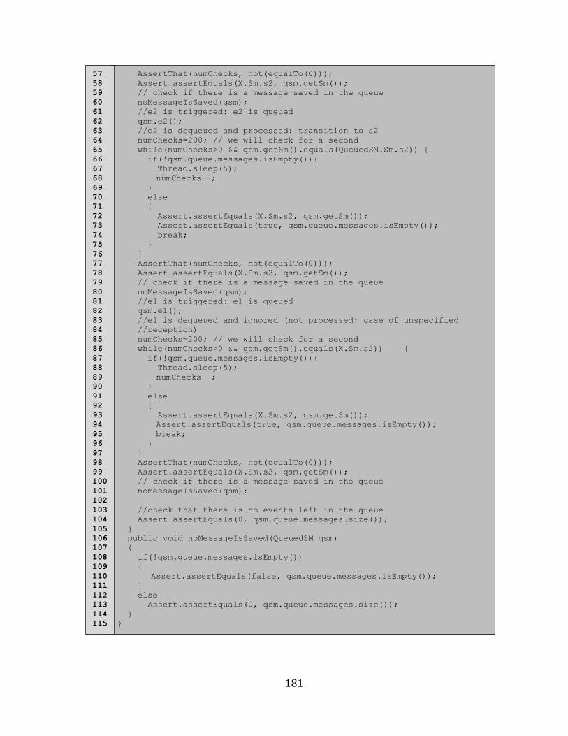
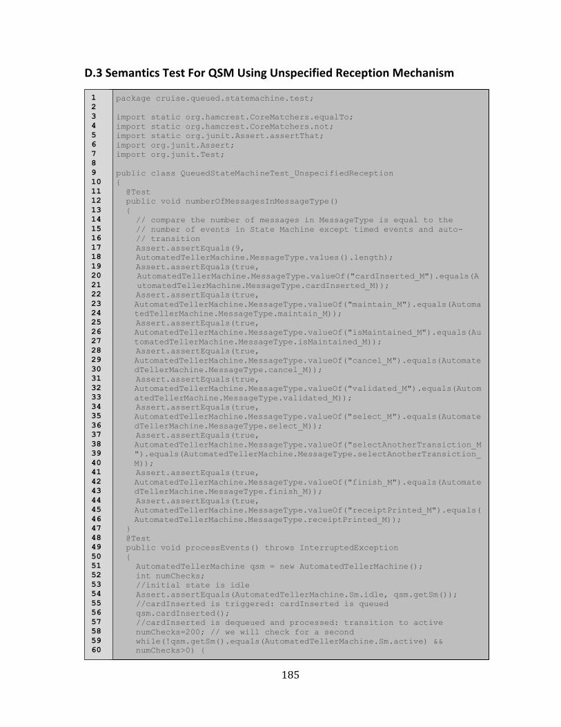
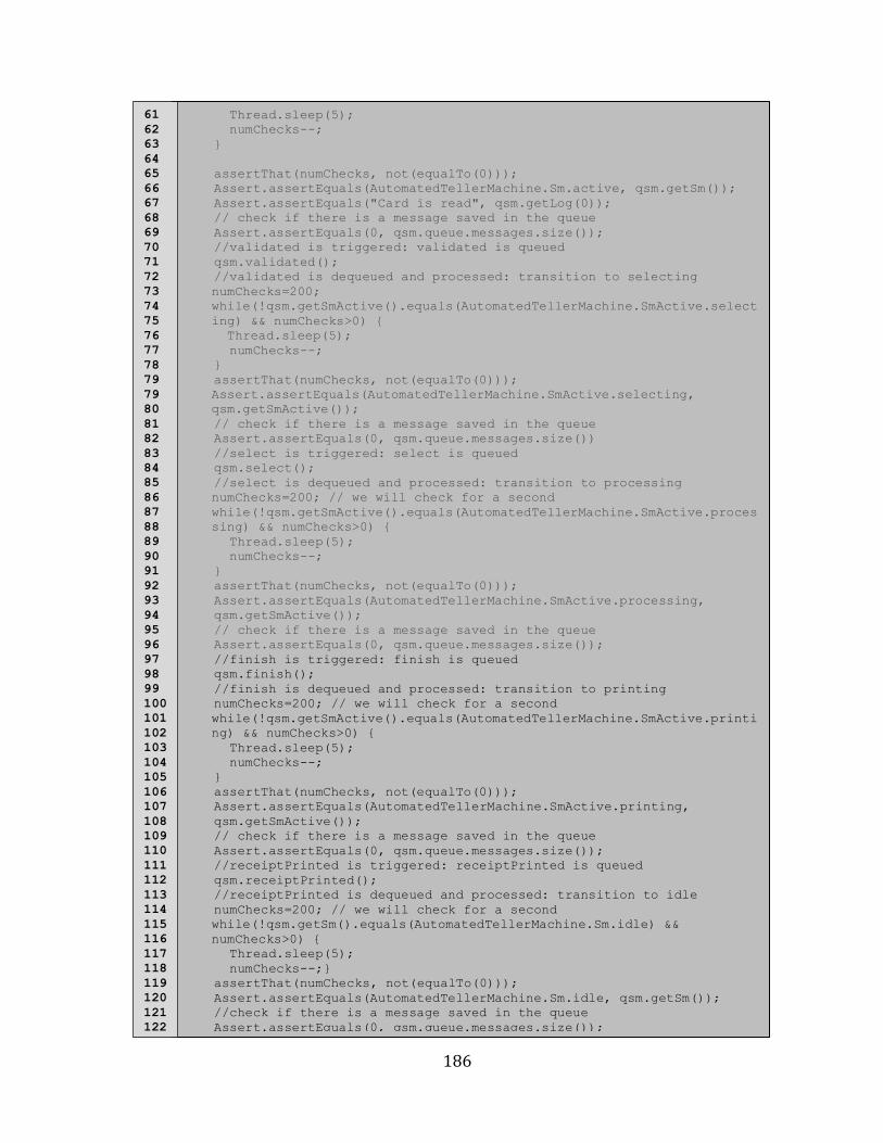
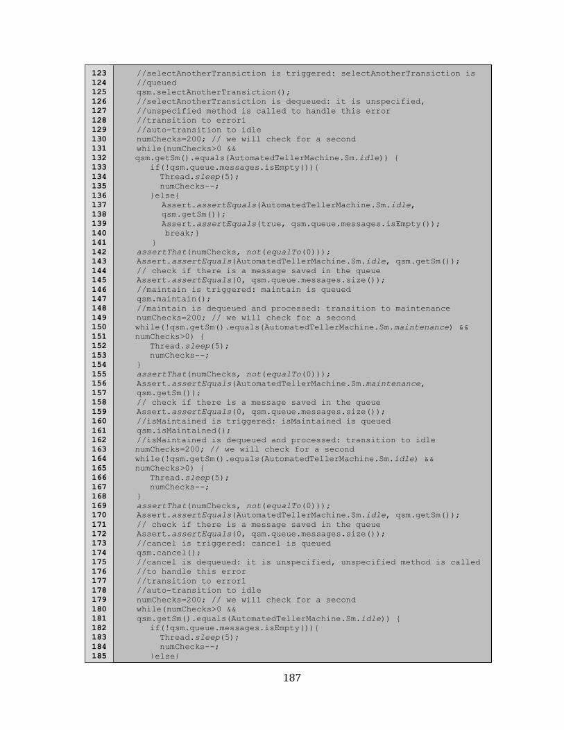
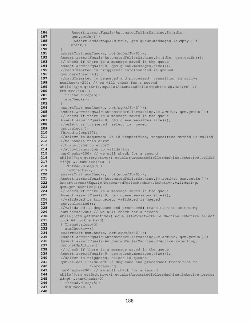
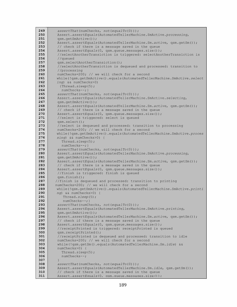
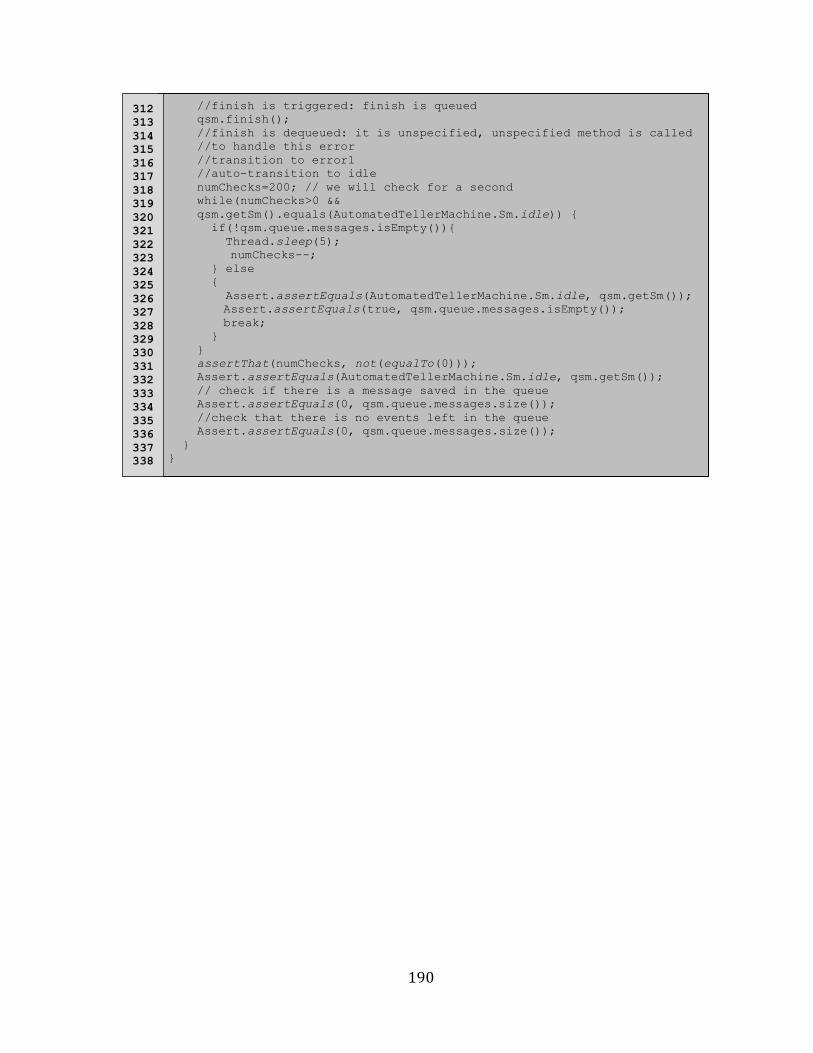
D.3 Semantics Test For QSM Using Unspecified Reception Mechanism .............................................. 185
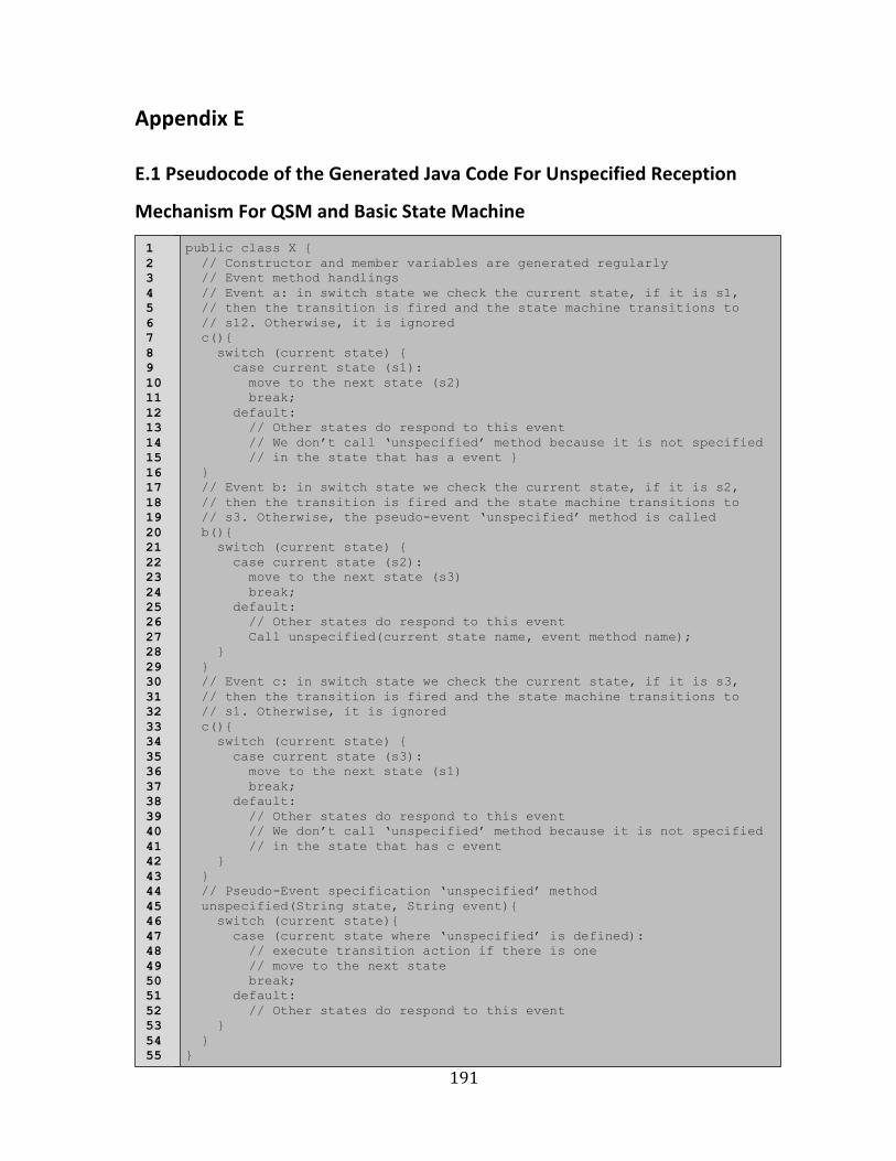
Appendix E .................................................................................................................................. 191
E.1 Pseudocode of the Generated Java Code For Unspecified Reception Mechanism For QSM and Basic State Machine .................................................................................................................................................... 191
Appendix F .................................................................................................................................. 192
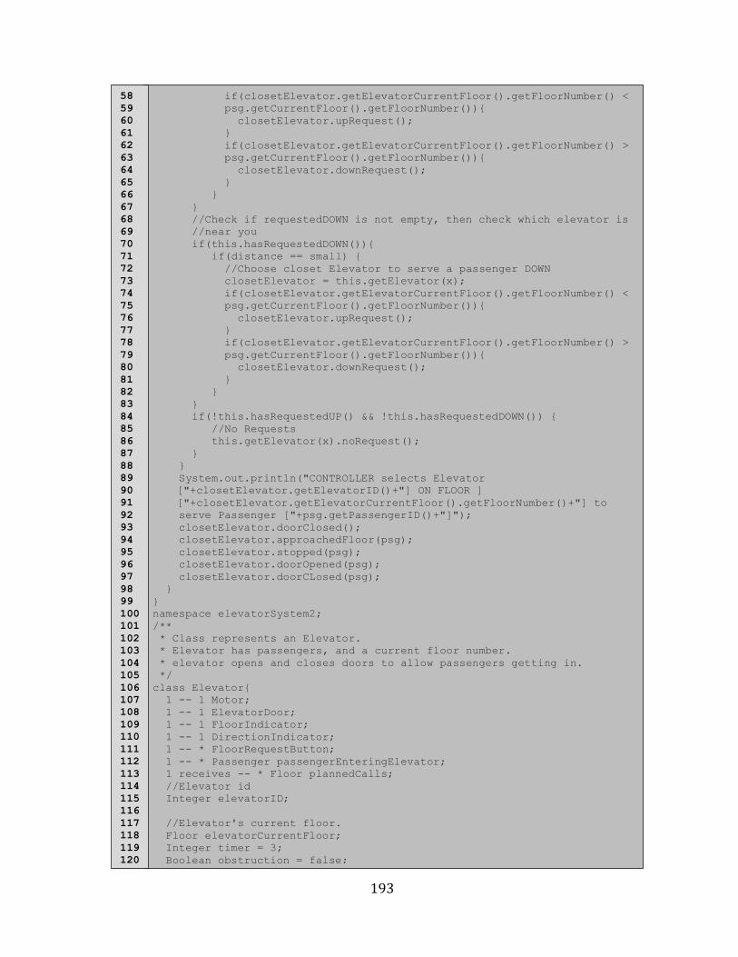
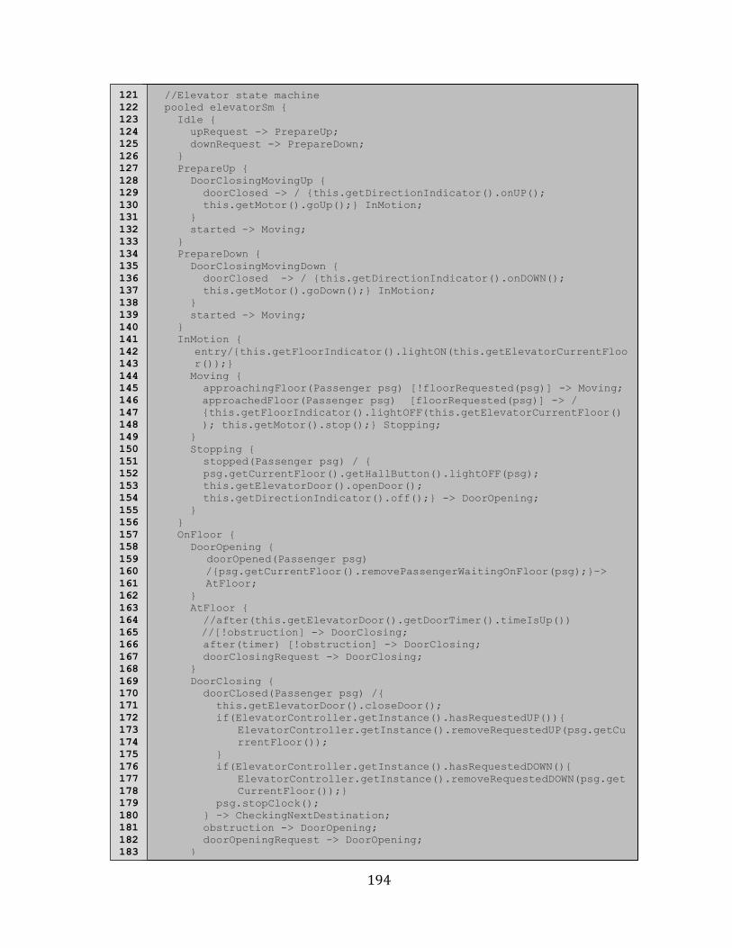
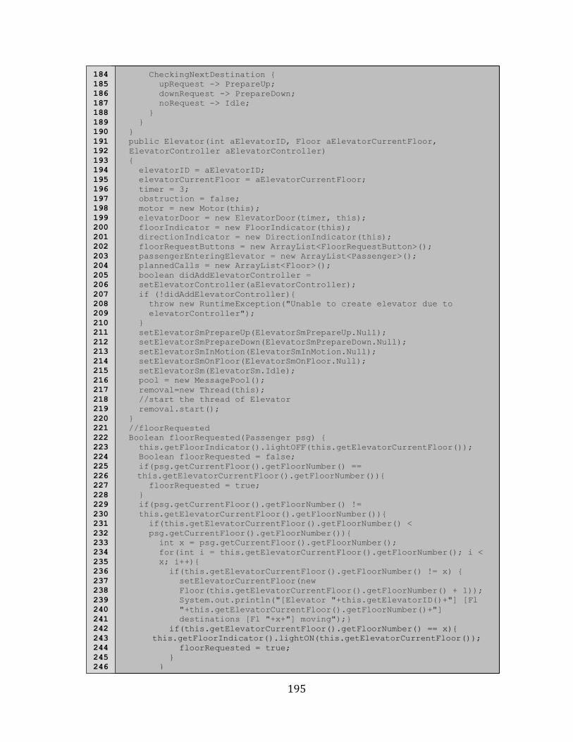
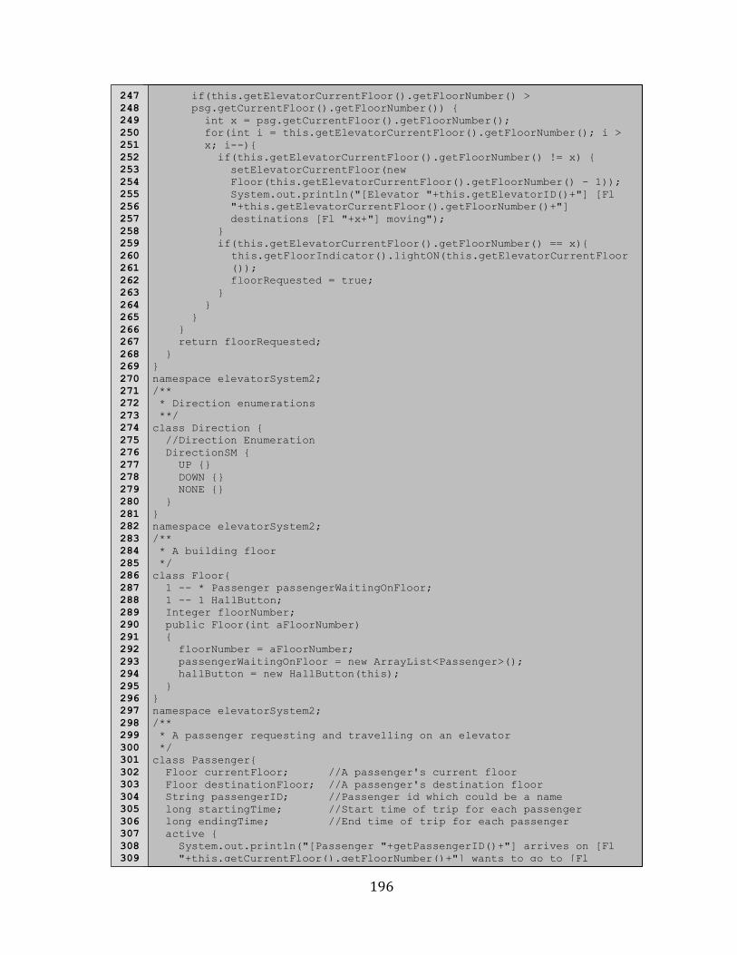
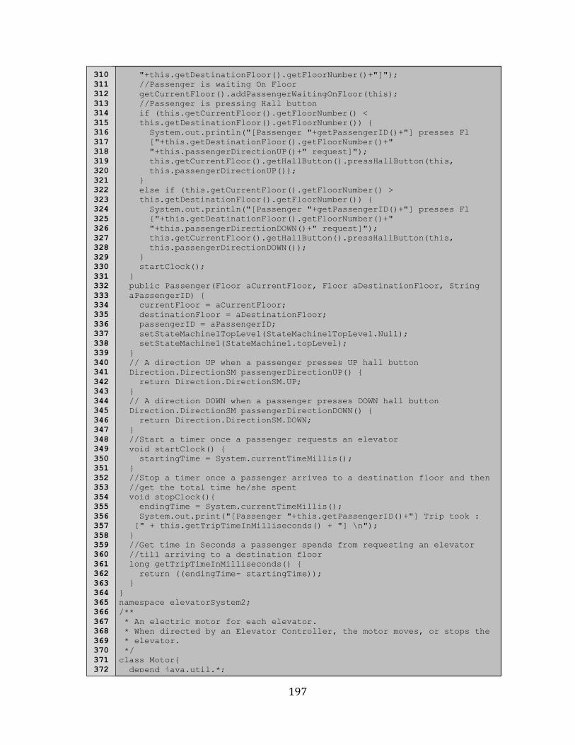
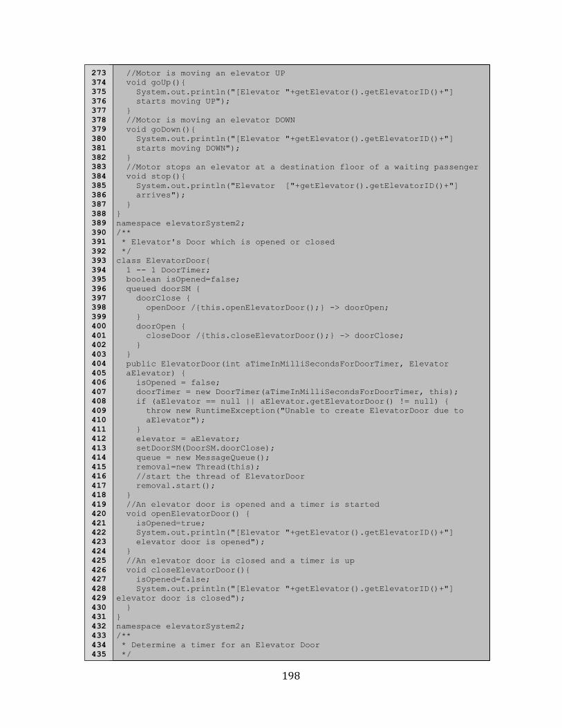
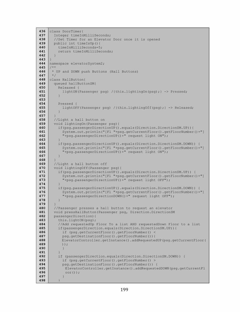
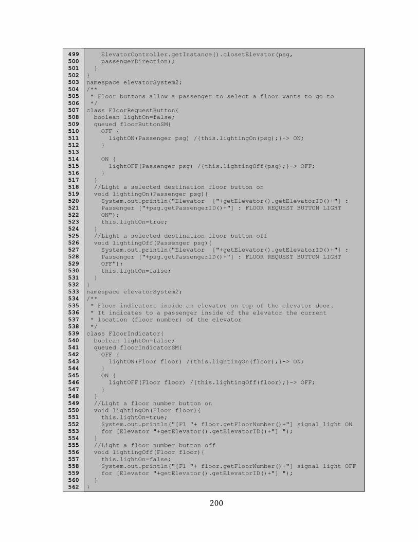
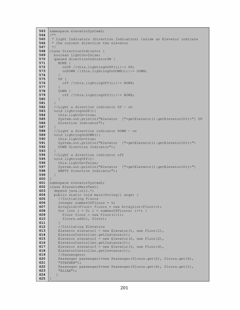
F.1 Umple Code For Elevator Controller System ............................................................................................ 192
ix
List of Figures
Figure 2.1: Umple metamodeling architecture by Almaghthawi, 2013...................................7
Figure 2.2: Umple model-‐oriented programming by Almaghthawi, 2013...........................10
Figure 2.3: State diagram and Umple code as shown in UmpleOnline..................................13
Figure 2.4: Textual and visual views of UmpleOnline...................................................................13
Figure 2.5: Umple well-‐defined components as shown by Badreddin, 2010.....................18
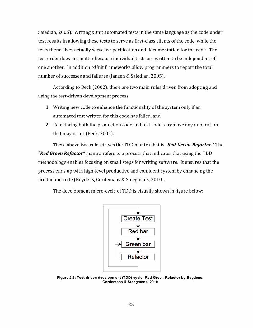
Figure 2.6: Test-‐driven development (TDD) cycle: Red-‐Green-‐Refactor by Boydens, Cordemans & Steegmans, 2010................................................................................................................25
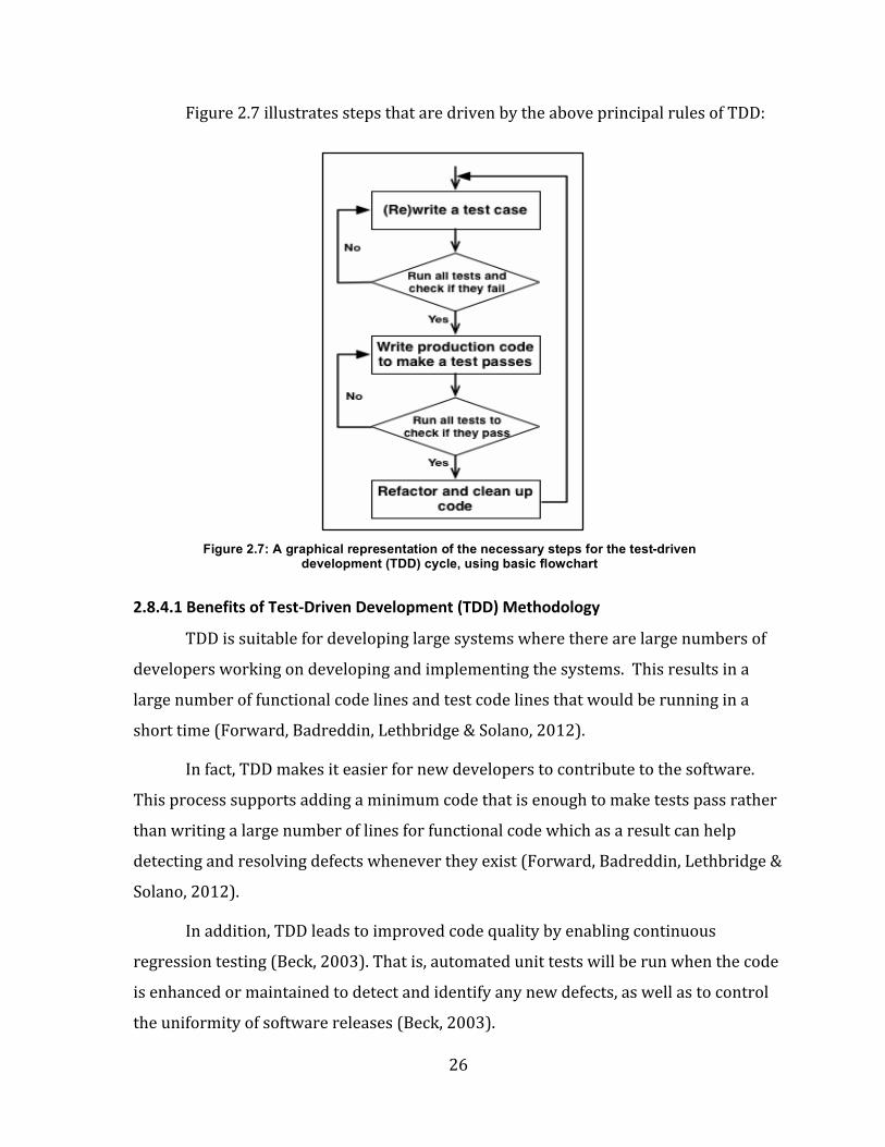
Figure 2.7: A graphical representation of the necessary steps for the test-‐driven development (TDD) cycle, using basic flowchart.............................................................................26
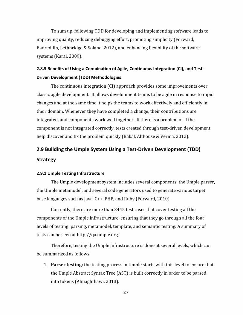
Figure 2.8: Umple testing infrastructure by Almaghthawi, 2013............................................29
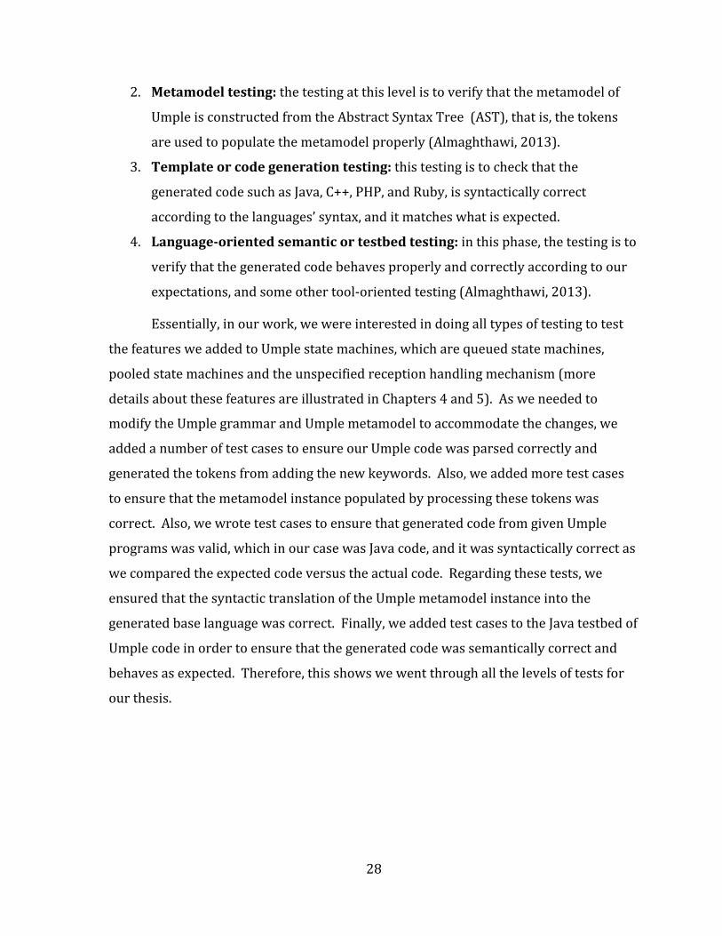
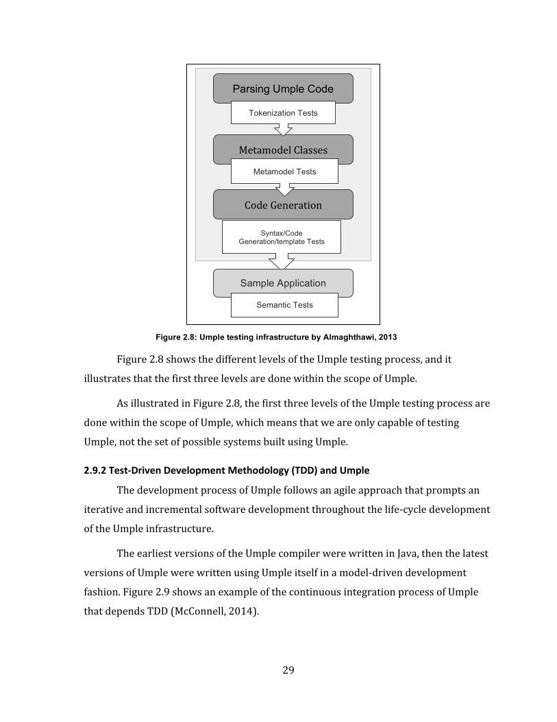
Figure 2.9: Umple continuous integration process relies on TDD by McConnell, 2014......................................................................................................................................................................30
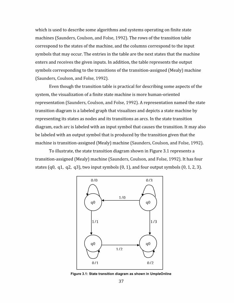
Figure 3.1: State transition diagram as shown in UmpleOnline...............................................37
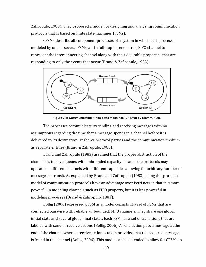
Figure 3.2: Communicating Finite State Machines (CFSMs) by Klemm, 1996....................40
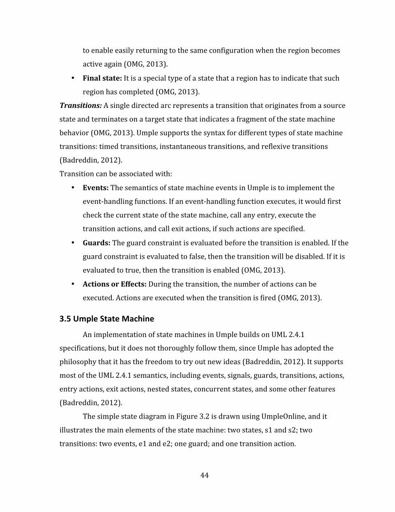
Figure 3.3: A simple state machine as shown in UmpleOnline.................................................45
Figure 3.4: State machine of TCP/IP simulation..............................................................................45
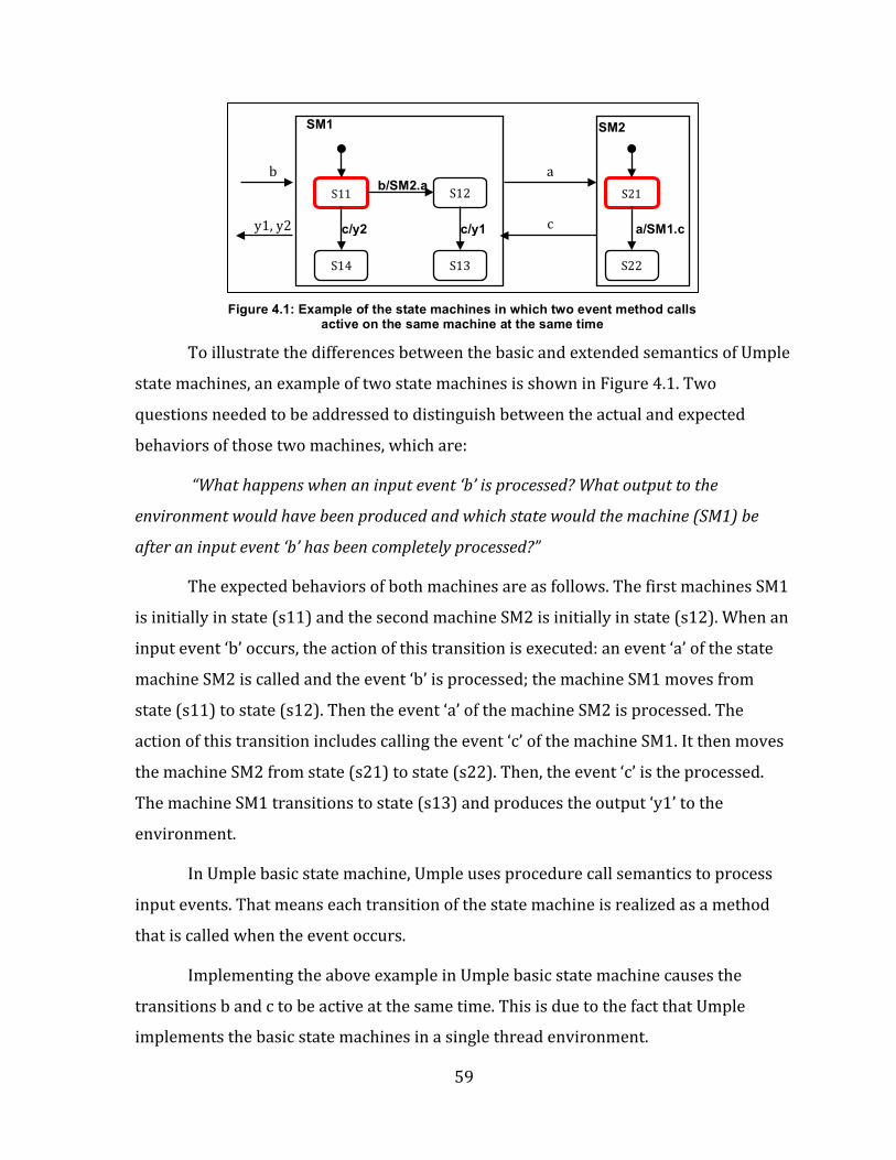
Figure 4.1: Example of the state machines in which two event method calls active on the same machine at the same time........................................................................................................59
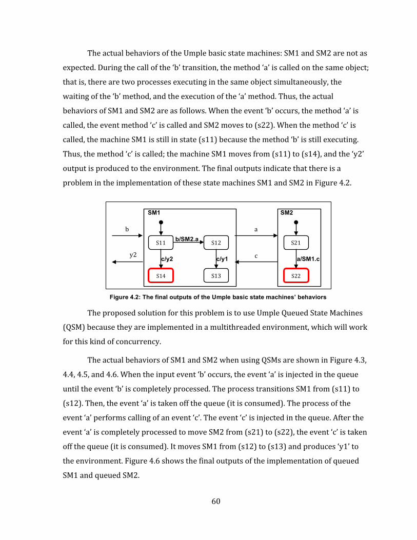
Figure 4.2: The final outputs of the Umple basic state machines’ behaviors......................60
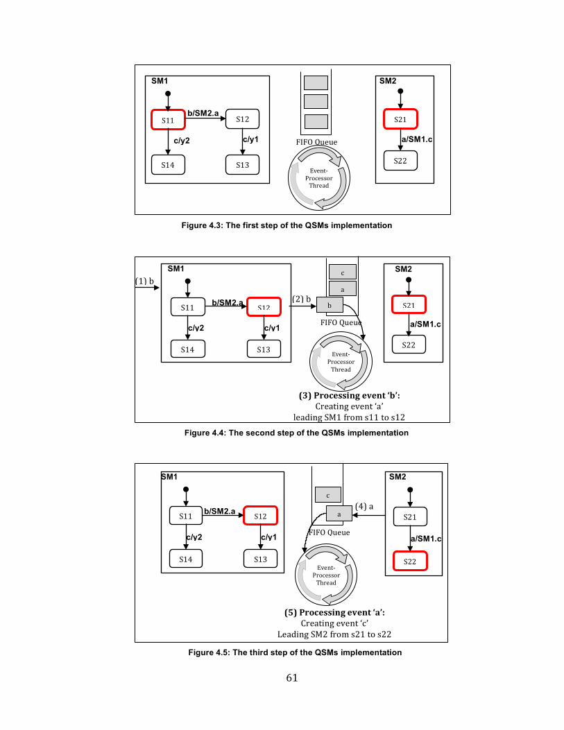
Figure 4.3: The first step of the QSMs implementation................................................................61
Figure 4.4: The second step of the QSMs implementation..........................................................61
Figure 4.5: The third step of the QSMs implementation..............................................................61
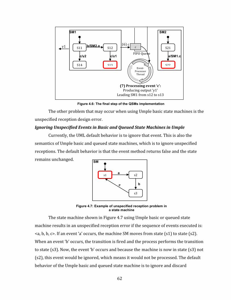
Figure 4.6: The final step of the QSMs implementation...............................................................62
Figure 4.7: Example of unspecified reception problem in a state machine.........................62
Figure 4.8: Using ‘unspecified’ transitions in states (s1) and (s3)..........................................64
Figure 4.9: The behavior of the pooled state machine (PSM)....................................................66
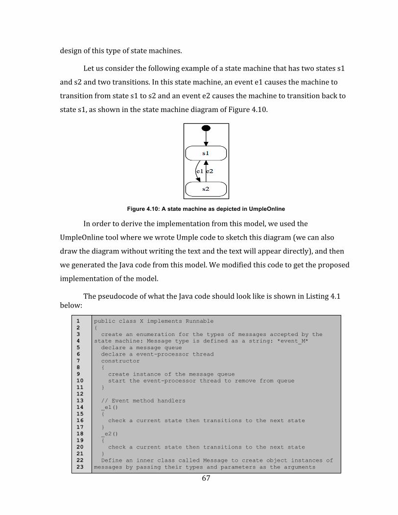
Figure 4.10: A state machine as depicted in UmpleOnline.........................................................67
x
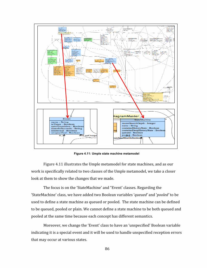
Figure 4.11: Umple state machine metamodel................................................................................86
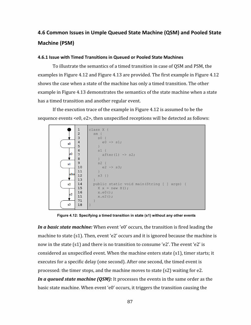
Figure 4.12: Specifying a timed transition in state (s1) without any other events..........87
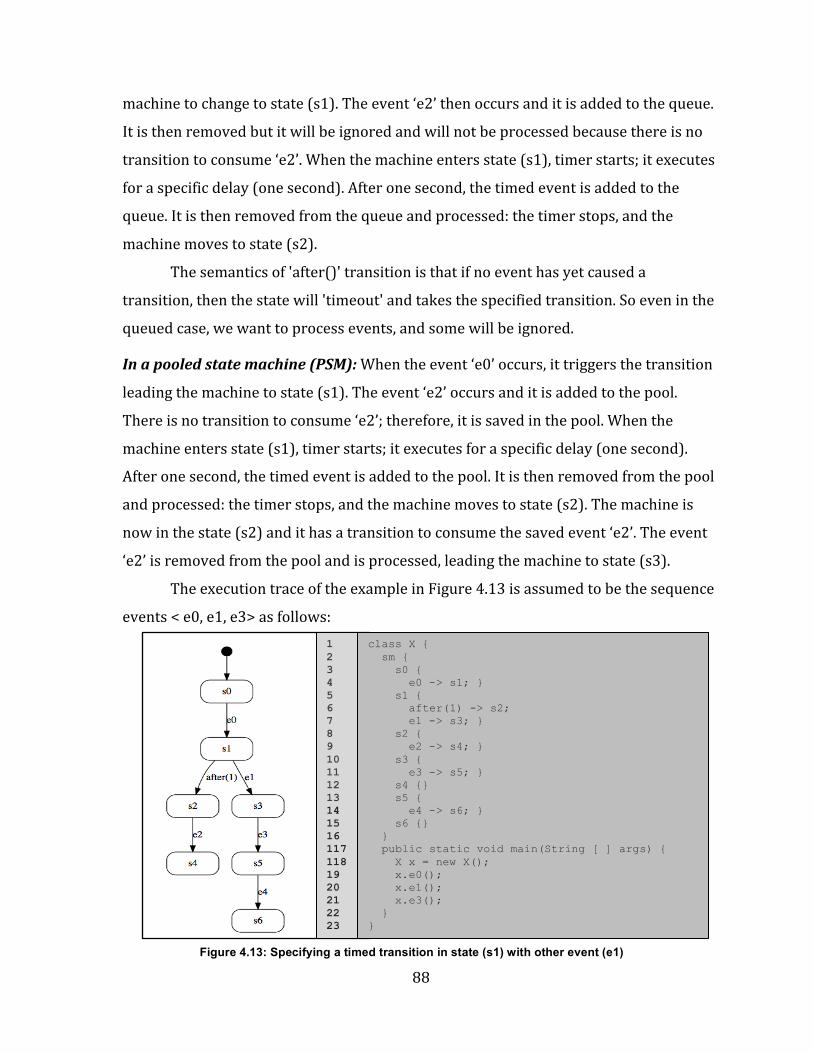
Figure 4.13: Specifying a timed transition in state (s1) with other events (e1)...............88
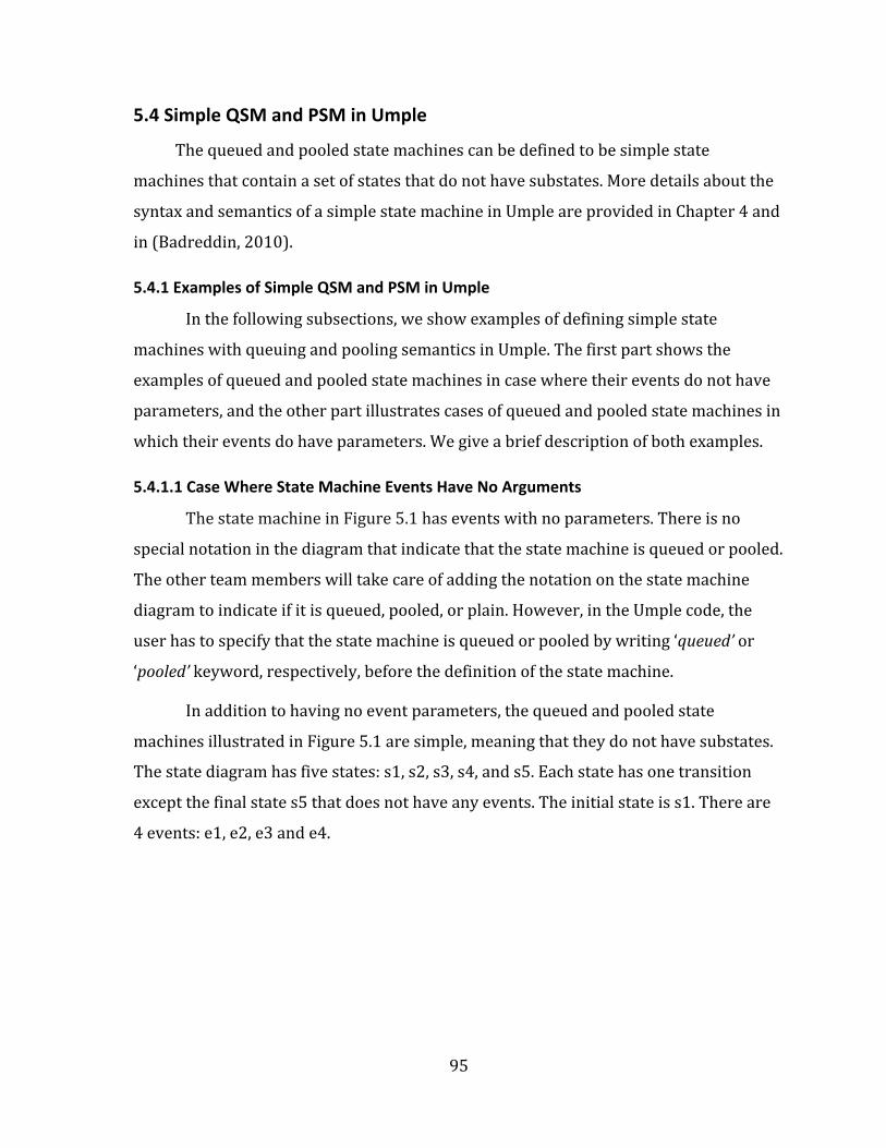
Figure 5.1: A simple state machine (events with no arguments) as shown in UmpleOnline.....................................................................................................................................................96
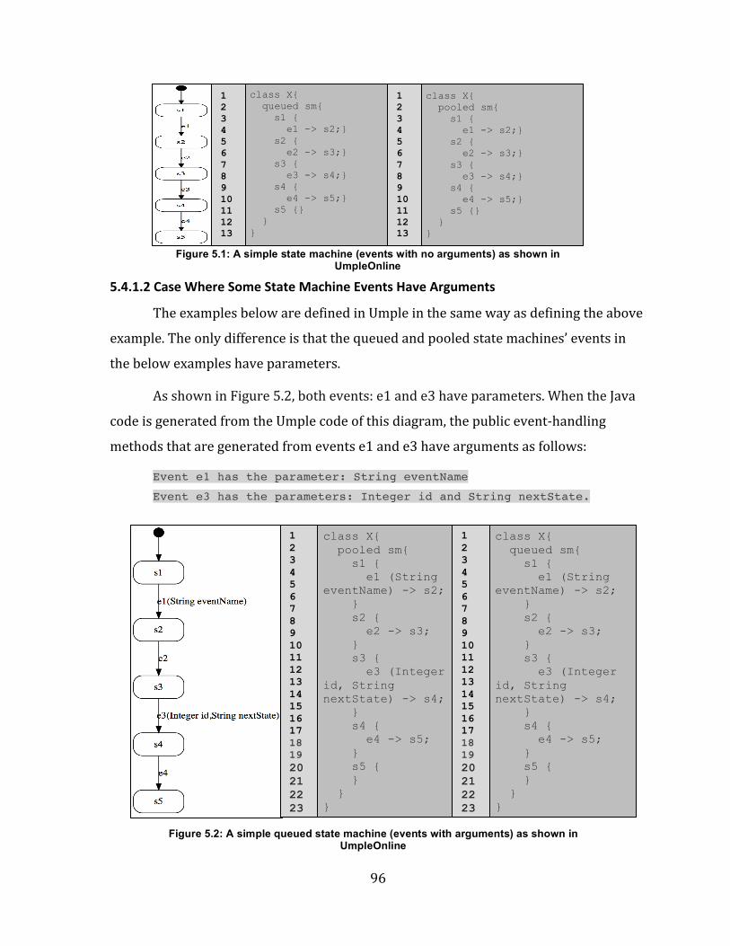
Figure 5.2: A simple queued state machine (events with arguments) as shown in UmpleOnline.....................................................................................................................................................96
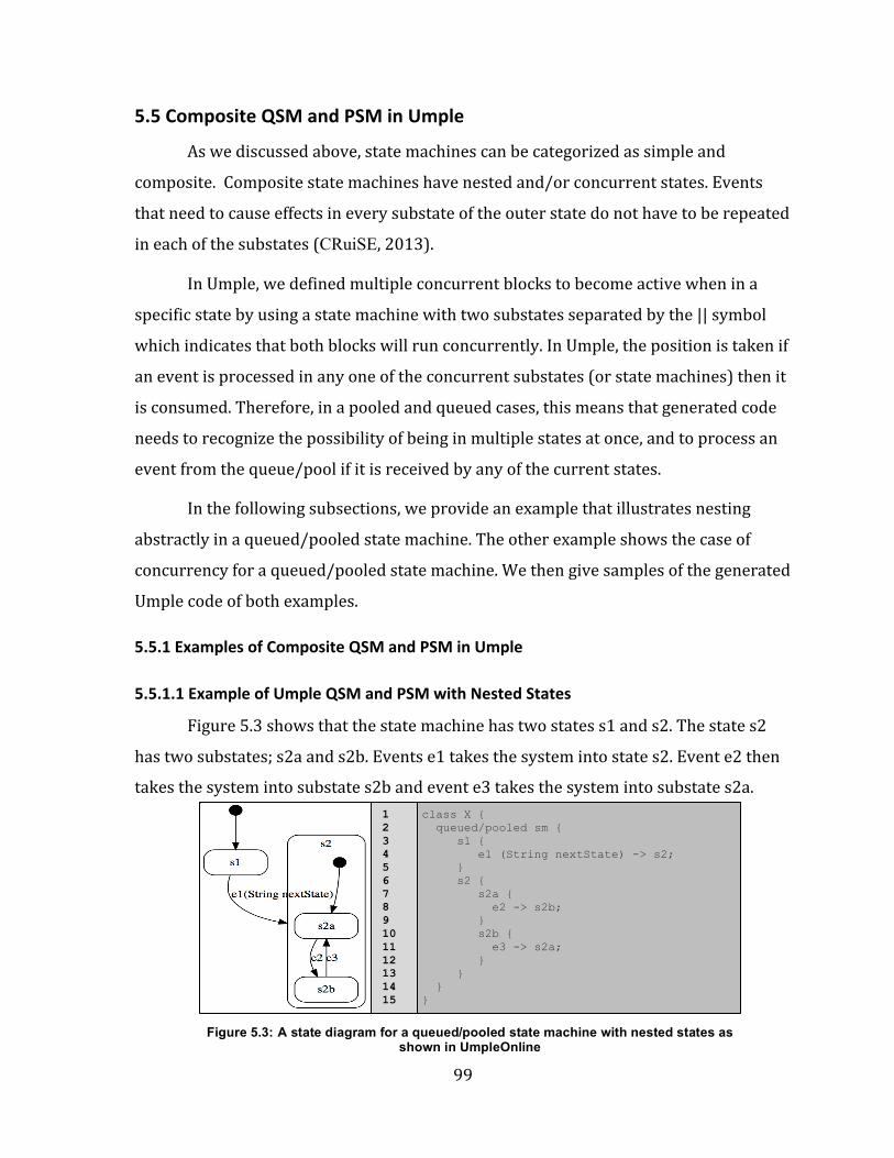
Figure 5.3: A state diagram for a queued/pooled state machine with nested states as shown in UmpleOnline.................................................................................................................................99
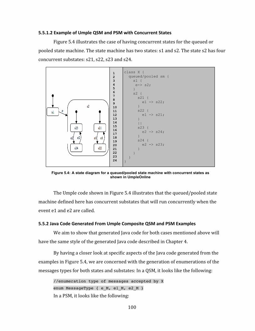
Figure 5.4: A state diagram for a queued state machine with concurrent states as shown in UmpleOnline..............................................................................................................................100
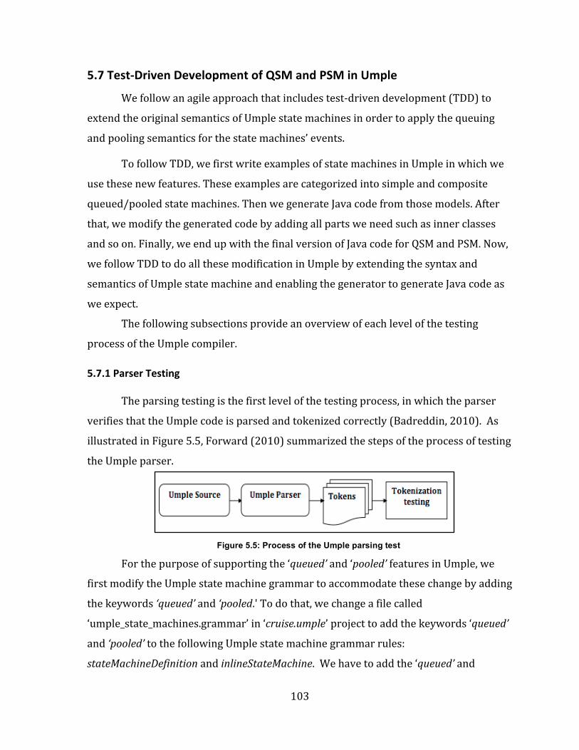
Figure 5.5: Process of the Umple parsing test................................................................................103
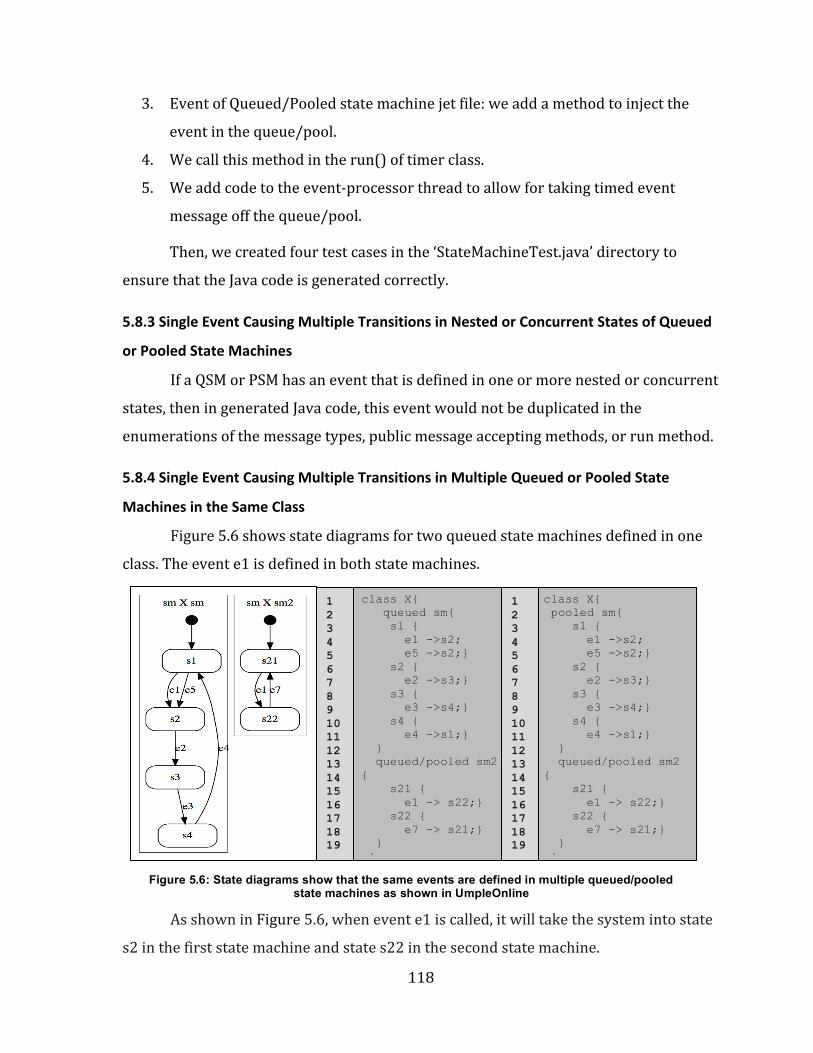
Figure 5.6: State diagrams show that the same events are defined in multiple queued/pooled state machines as shown in UmpleOnline.......................................................118
Figure 5.7: A state diagram for multiple queued state machines in one class as shown in UmpleOnline.............................................................................................................................................120
Figure 5.8: State diagrams for two queued state machines (sm and sm1) and one eventless state machine (sm2) as shown in UmpleOnline.........................................................124
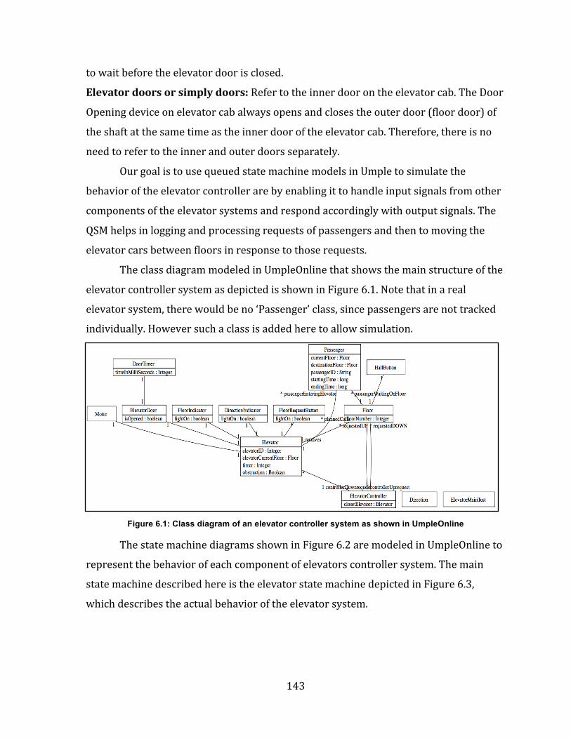
Figure 6.1: Class diagram of an elevator controller system as shown in UmpleOnline...................................................................................................................................................143
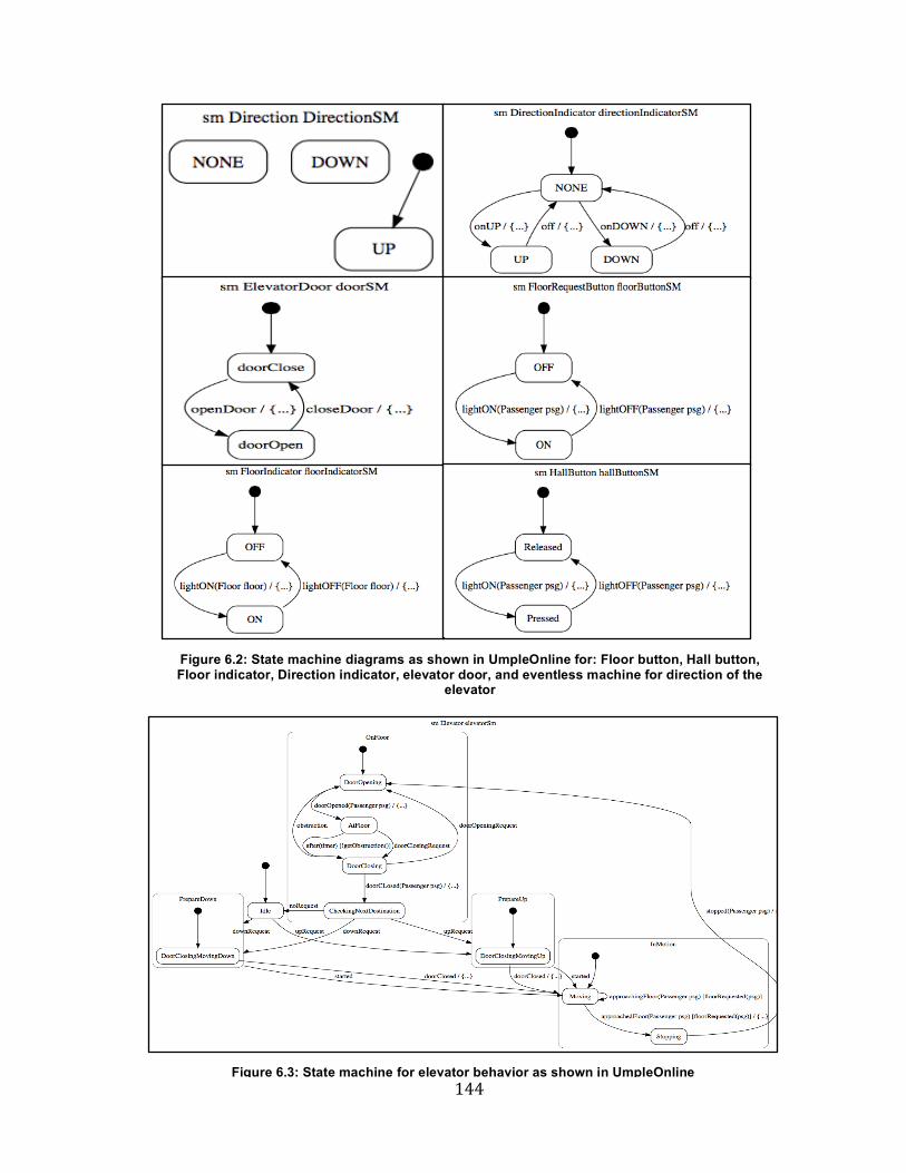
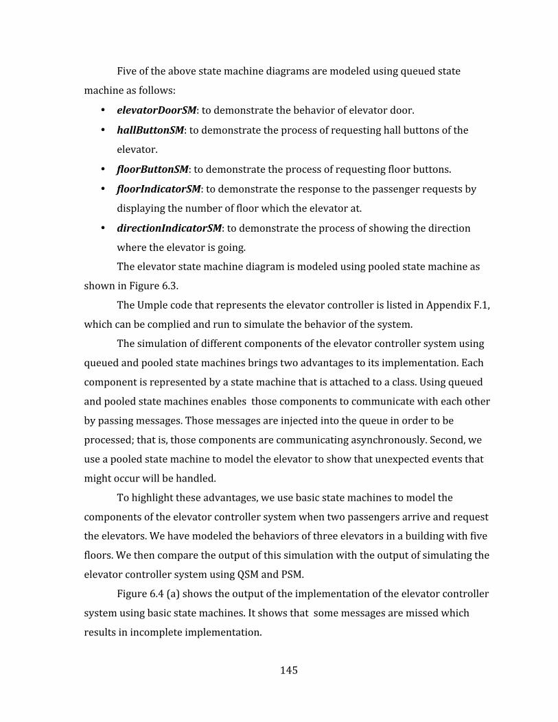
Figure 6.2: State machine diagrams as shown in UmpleOnline for: Floor button, Hall button, Floor indicator, Direction indicator, elevator door, and eventless machine for direction of the elevator............................................................................................................................144
Figure 6.3: State machine for elevator behavior as shown in UmpleOnline.....................144
Figure 6.4: Simulation outputs of Elevator Controller System example...........................146
xi
List of Tables
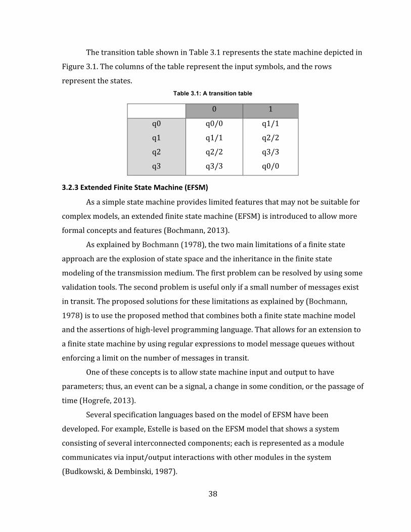
Table 3.1: A transition table.....................................................................................................................38
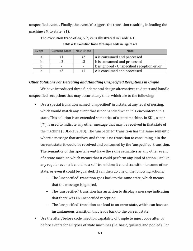
Table 4.1: Execution trace for Umple code in Figure 4.1.............................................................63
Table 4.2: Execution trace for example in Figure 4.8....................................................................65
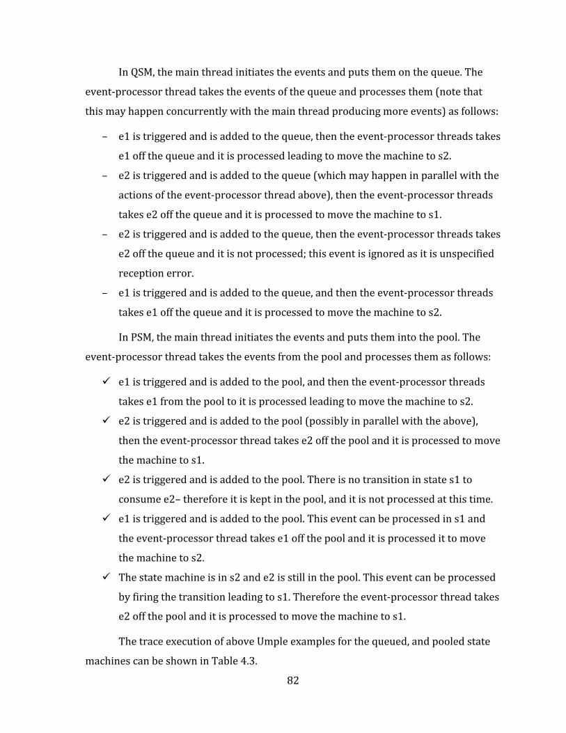
Table 4.3: Execution trace of Umple code for basic, queued, and pooled state machines.............................................................................................................................................................83
Table 5.1: Execution trace of Umple code that is shown in Listing 5.1..................................94
Table 5.2: Key Jet templates for generation of queued and pooled state machines......102
Table 5.3: Different test cases of unspecified reception handler mechanism for the basic and queued state machines..........................................................................................................126
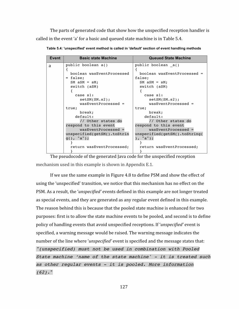
Table 5.4: 'unspecified' event method is called in 'default' section of event handling methods............................................................................................................................................................127
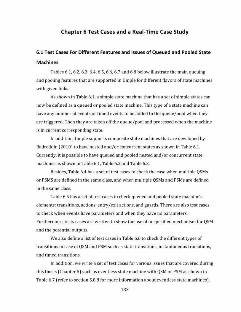
Table 6.1: Umple test cases for both flavors of Umple state machines...............................134
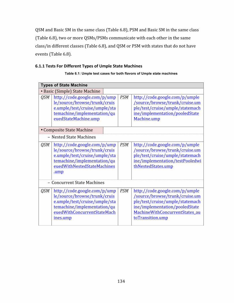
Table 6.2: Umple test cases for QSM and PSM in case of nested state machines............135
Table 6.3: Umple test cases for QSM and PSM in case of concurrent states.....................135
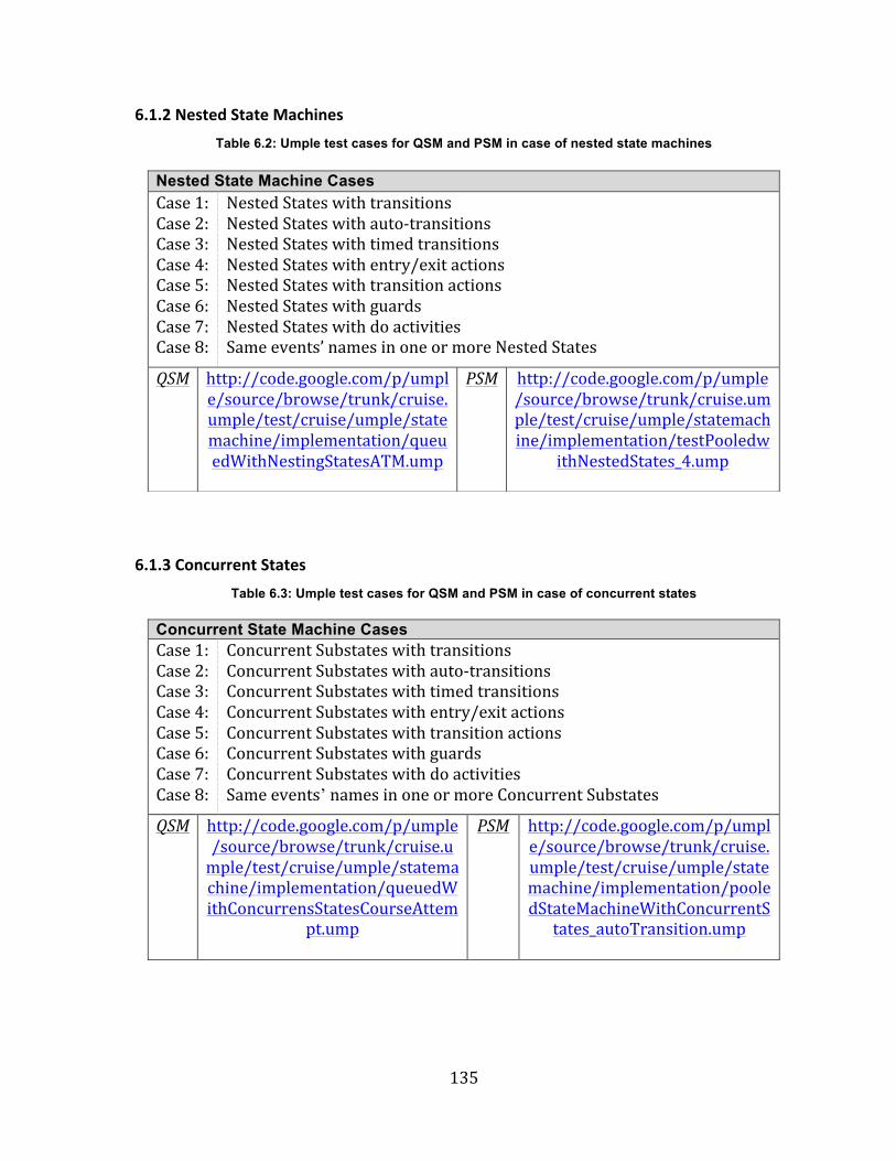
Table 6.4: Umple test cases for case of multiple queued /pooled state machines in the same class........................................................................................................................................................136
Table 6.5: Umple test cases for different elements of Umple state machine....................137
Table 6.6: Umple test cases for different types of Umple state machine transitions....138
Table 6.7: Umple test cases for Umple eventless state machines..........................................139
Table 6.8: Umple test cases for other common issues in QSM and PSM.............................140
xii
List of Listings
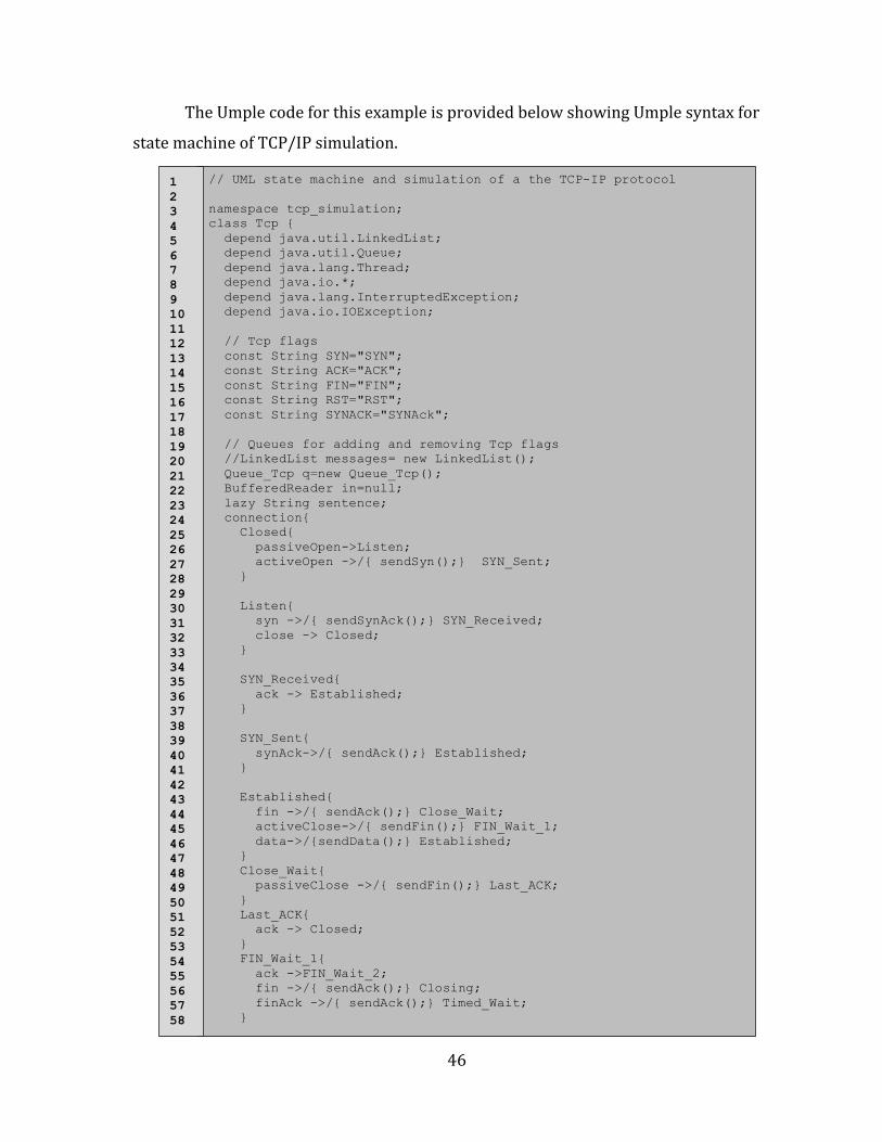
Listing 3.1: Umple syntax for TCP/IP simulation state machine..............................................47
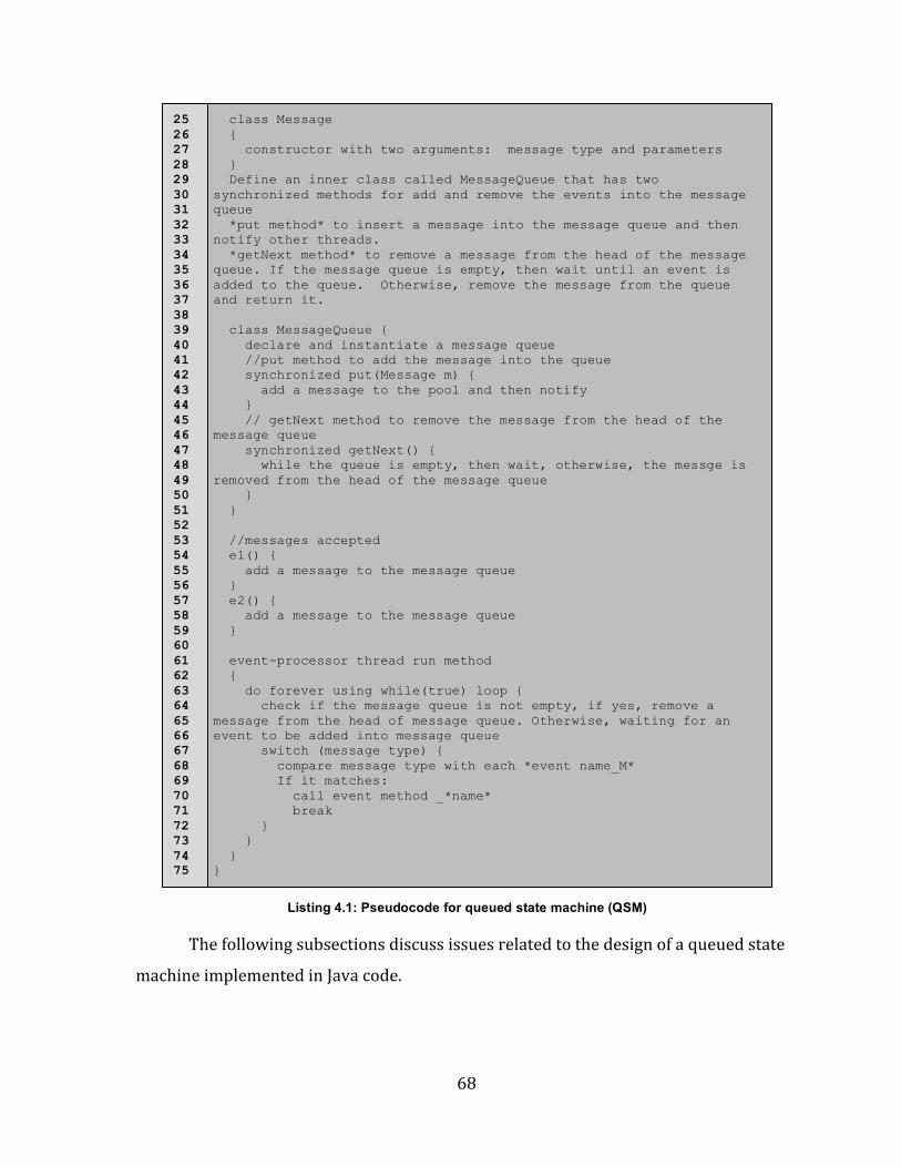
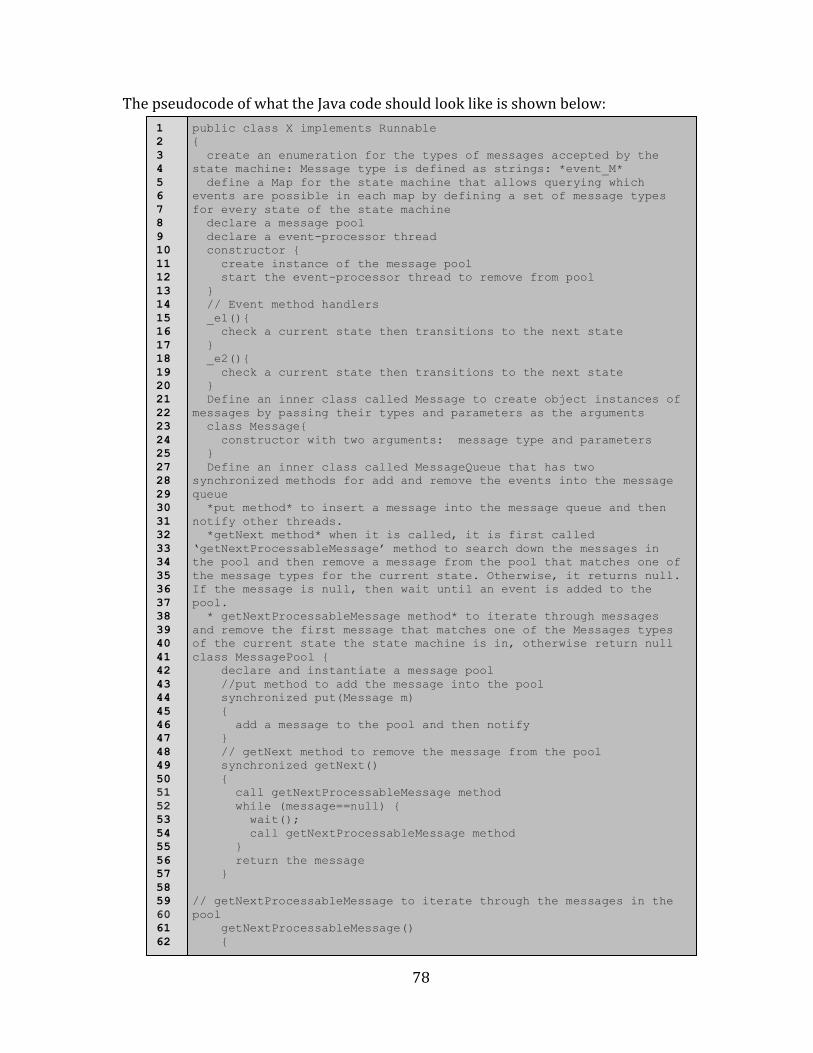
Listing 4.1: Pseudocode for queued state machine (QSM)..........................................................68
Listing 4.2: Pesudocode for pooled state machine (PSM)...........................................................79
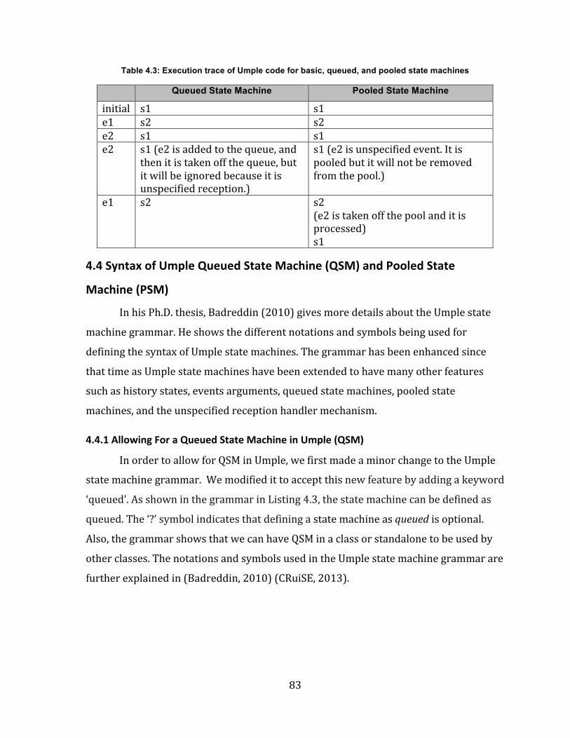
Listing 4.3: Umple grammar to specify ‘queued’ and ‘pooled’ keywords.............................84
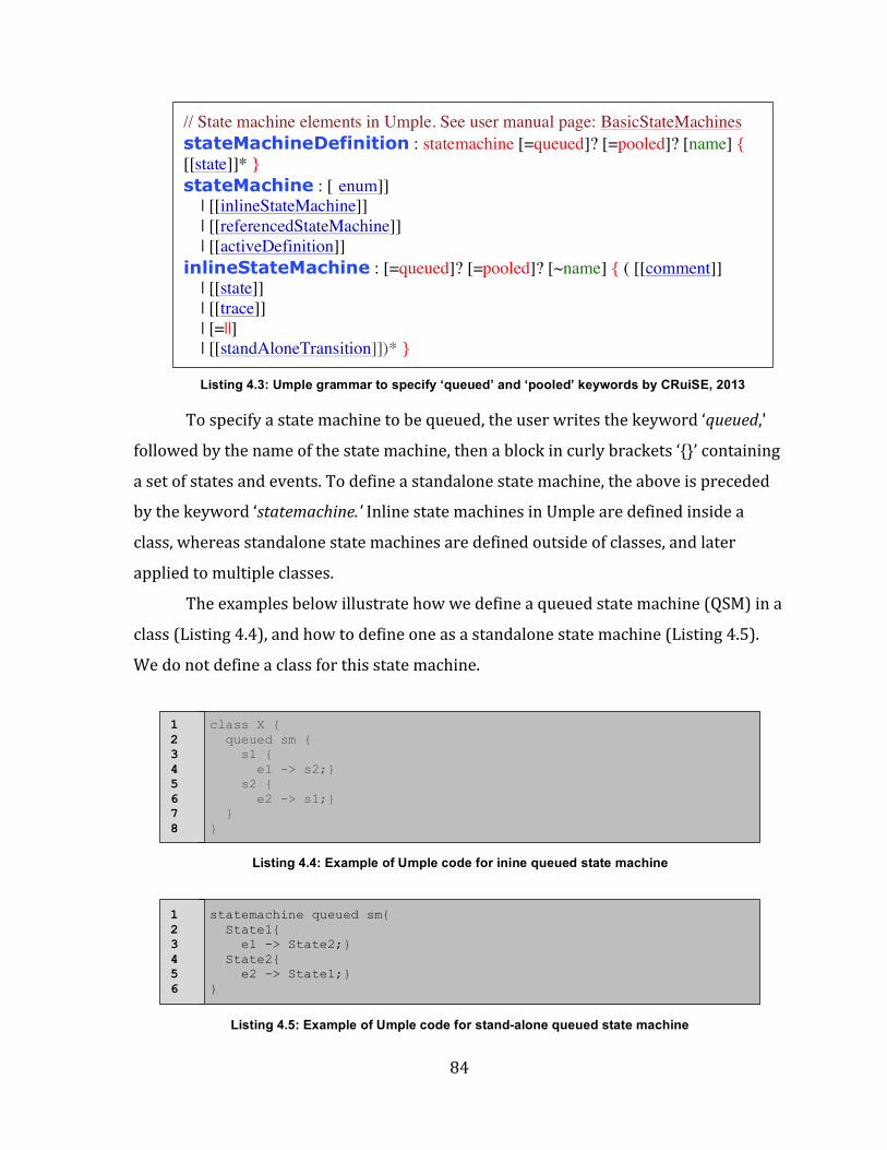
Listing 4.4: Example of Umple code for the queued state machine.........................................84
Listing 4.5: Example of Umple code for inline queued state machine...................................84
Listing 4.6: An error message raised if a state machine is defined as queued and pooled at same time......................................................................................................................................................85
Listing 5.1: An Umple code example of basic, queued, and pooled state machines.........93
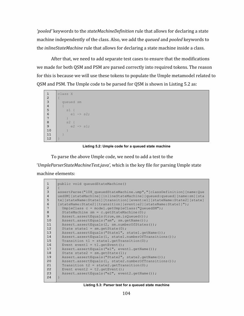
Listing 5.2: Umple code for a queued state machine..................................................................104
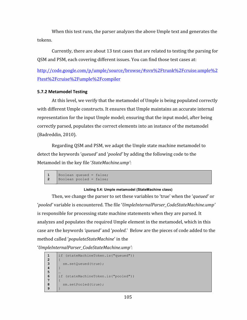
Listing 5.3: Parser test for a queued state machine....................................................................104
Listing 5.11: Example of defining basic, queued, and pooled state machines in one class....................................................................................................................................................................123
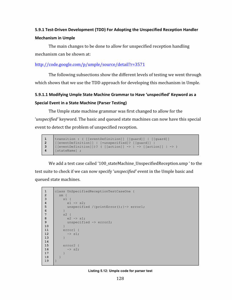
Listing 5.12: Umple code for parser test..........................................................................................128
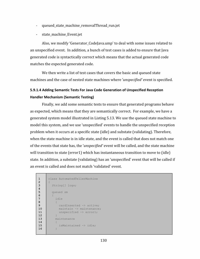
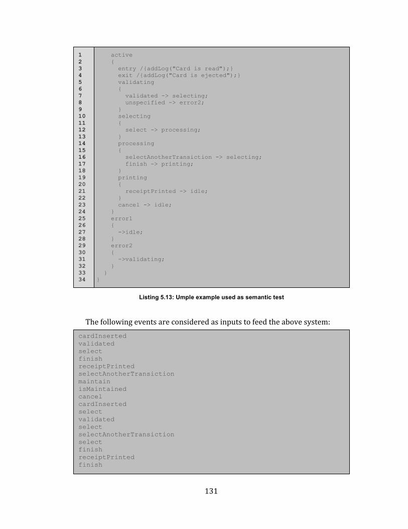
Listing 5.13: Umple example used as semantic test....................................................................131
xiii
Abbreviations
CFSM: Communicating Finite State Machine.
EFSM: Extended Finite State Machine.
FDT: Formal Description Techniques.
FIFO: First-‐In First-‐Out.
FSM: Finite State Machine.
HFSM: Hierarchical Finite State Machine.
MDD: Model-‐Driven Development.
PSM: Pooled State Machine.
QSM: Queued State Machine.
SDL: Specification and Description Language.
TDD: Test-‐Driven Development.
UML: Unified Modeling Language.
Umple: UML Programming Language, Simple, and Ample.
1
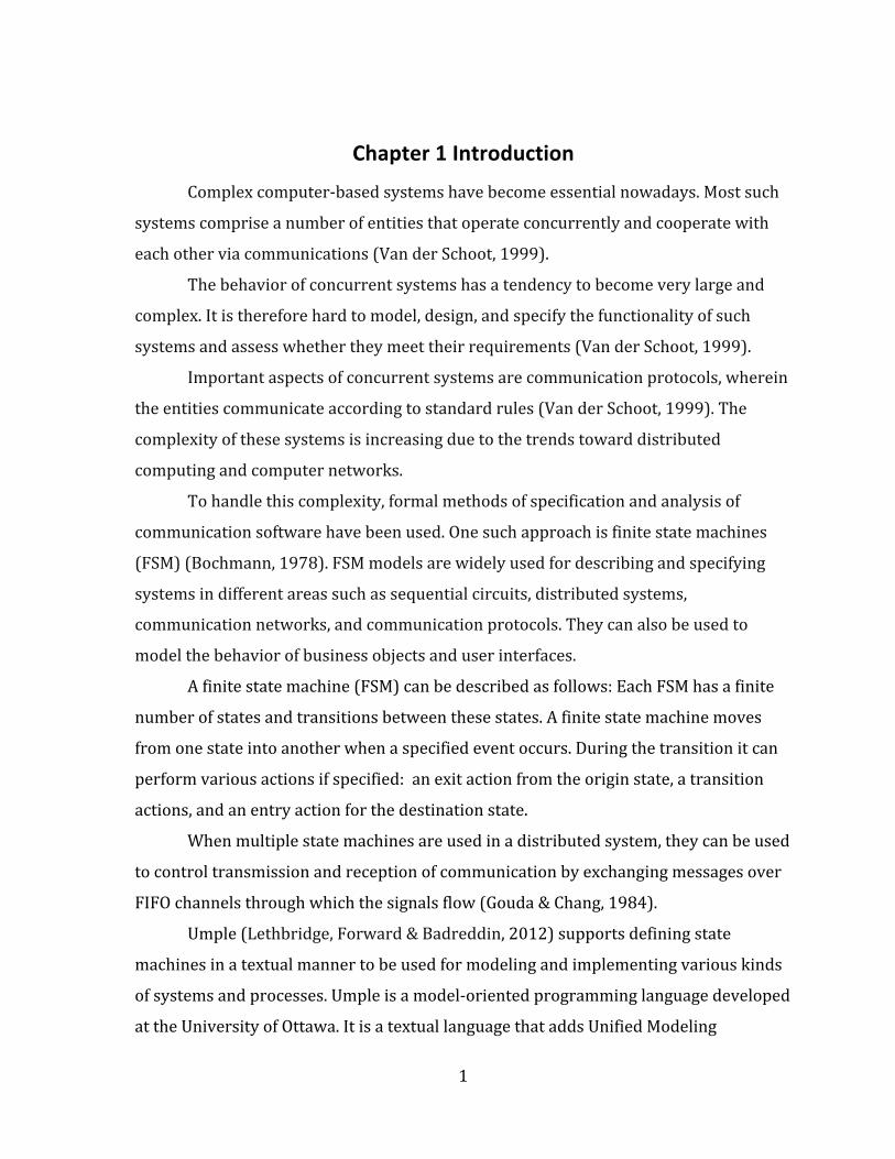
Chapter 1 Introduction
Complex computer-‐based systems have become essential nowadays. Most such
systems comprise a number of entities that operate concurrently and cooperate with
each other via communications (Van der Schoot, 1999).
The behavior of concurrent systems has a tendency to become very large and
complex. It is therefore hard to model, design, and specify the functionality of such
systems and assess whether they meet their requirements (Van der Schoot, 1999).
Important aspects of concurrent systems are communication protocols, wherein
the entities communicate according to standard rules (Van der Schoot, 1999). The
complexity of these systems is increasing due to the trends toward distributed
computing and computer networks.
To handle this complexity, formal methods of specification and analysis of
communication software have been used. One such approach is finite state machines
(FSM) (Bochmann, 1978). FSM models are widely used for describing and specifying
systems in different areas such as sequential circuits, distributed systems,
communication networks, and communication protocols. They can also be used to
model the behavior of business objects and user interfaces.
A finite state machine (FSM) can be described as follows: Each FSM has a finite
number of states and transitions between these states. A finite state machine moves
from one state into another when a specified event occurs. During the transition it can
perform various actions if specified: an exit action from the origin state, a transition
actions, and an entry action for the destination state.
When multiple state machines are used in a distributed system, they can be used
to control transmission and reception of communication by exchanging messages over
FIFO channels through which the signals flow (Gouda & Chang, 1984).
Umple (Lethbridge, Forward & Badreddin, 2012) supports defining state
machines in a textual manner to be used for modeling and implementing various kinds
of systems and processes. Umple is a model-‐oriented programming language developed
at the University of Ottawa. It is a textual language that adds Unified Modeling
2
Language (UML) state machines, and class models to well-‐known object-‐oriented
programming languages such as Java, PHP, C++ and Ruby. It also supports software
patterns such as singleton (Almaghthawi, 2013).
Badreddin (2012) discussed in his PhD thesis the development process for the
syntax and semantics of state machines in Umple. He completed the design and
implementation of the first version of state machines in Umple. Moreover, he illustrated
how the modeling concepts and code of state machines and other system aspects can be
integrated in the same artifact; this allows developers to model and write code at the
same time (Badreddin, 2012).
However, in the version of Umple as it stood at the time the current thesis
research was started, there was no feature that allowed for state machines to
communicate via FIFO queues. Events were implemented as synchronous method calls,
and, the same thread that called the event was responsible for processing the state
transition, as well as any entry, exit and transition actions. This implementation could
be very useful to control the state of a single object, but was impractical in multi-‐
threaded software, and could give rise to deadlock, among other problems.
Therefore, we set out to enhance the code generated from Umple so events
would be queued; the caller would enter the event in the queue and then continue. This
would allow state machines to communicate asynchronously by passing messages in a
FIFO manner, and where the output message of one state machine becomes the input
for another. The caller of an event message does not have to wait for the state machine
to process all of its actions, as had been required in basic state machines in Umple. We
call this new extension queued state machines (QSM).
Also, we add so-‐called pooled state machines (PSM). Pooled state machines
extend QSM as follows. In original Umple state machines, and queued state machines, if
an event arrives while in a state that is not programmed to respond to that state, then
the event is ignored and discarded. This problem is called unspecified reception. In
PSM, the event is retained at the front of the queue until the system enters a state in
which the event can be consumed. Events further back in the queue are processed in
the meantime. Among other things, PSM can handle events arriving at unexpected
times.
3
A third feature added is the capability to handle unspecified receptions by
designating a transition to be taken when an unexpected event arrives.
An additional feature added to Umple in this thesis is the ability to allow state
machine events to have parameters of any type. This makes Umple conform more
closely to UML specifications, in which signals and call events can have parameters.
In order to achieve these extensions to Umple, we followed a Test-‐Driven
Development (TDD) methodology. Test-‐driven development encourages short
development cycles or iterations and requires writing tests before releasing any
incremental change (Patrick, 2006). The process essentially is to write test code before
writing functional code. When these tests are first run, they fail because the desired
behavior does not exist yet. To pass these tests, new code is produced. Now, running
test code again passes. Finally, the new code is refactored to acceptable standards and
to remove any duplications that may occur (Ambler, 2012).
Refactoring the existing design locally enables changing the part of the design
that is affected by the new feature a developer wants to implement. This process results
in enhancing the quality of the design and makes it easier to work with it in the future.
In fact, TDD helps derive the design of the code as well as validate it (Ambler, 2012).
Therefore, we go through several steps as a whole cycle consists of extending
Umple sate machine grammar with new syntax, instantiating Umple metamodel, as well
as generating appropriate code in the target language (Java) in order to implement
those new features.
1.1 Goal of the Thesis
The main goal of this thesis is to extend the Umple model-‐oriented programming
language in order to provide for queued and pooled state machines, a well as event
arguments and unspecified reception transitions. The thesis will show how we
implemented this feature following the test-‐driven approach.
The resulting generated code will be more complex but it will work in a multi-‐
threaded environment and allow asynchronous calls to events.
4
1.2 Research Questions
The current thesis will address the following three research questions:
• How can the Umple Language be extended to have queued and pooled state
machines?
• How could the messages be encoded when they are passed between state
machines?
• How can one deal with cases of unspecified receptions, for example, error
messages?
1.3 Thesis Outline
The thesis is documented and organized in the following manner.
In Chapter 2, we provide some background information related to the Umple
model-‐oriented programming language, showing its development infrastructure and its
different tools. We also give an overview of the methodologies used to developing
Umple.
In Chapter 3, we focus on the literature review of formal description techniques
(FDTs) used for specifying and describing communication protocols and distributed
systems. We provide a brief overview of some general design errors, and we outline
some proposed solutions for handling them.
In Chapter 4, we discuss our design of queued state machine (QSMs), and we
also provide the design of a pooled state machine (PSMs). We show Java code for QSM
and PSM, and we discuss the different design alternatives we have for QSM and PSM. In
addition, we demonstrate the syntax and semantics of QSM and PSM in Umple.
Chapter 5 discusses the implementation of QSM and PSM in Umple showing
some examples of generated Java code from simple and composite QSM and PSM. We
also discuss various issues related to the design and implementation of QSM and PSM.
Besides, we give an overview of proposed unspecified reception mechanisms in Umple.
5
In Chapter 6, we show some test cases of QSM, PSM, and the unspecified
reception mechanism in Umple. Also, we provide an example showing the usefulness of
QSM in Umple.
Finally, in Chapter 7, we conclude our thesis and discuss different possibilities
for future work.
6
Chapter 2 Umple: A Model-‐Oriented Programming Language
2.1 Introduction to Umple
Umple is a model-‐oriented programming language developed at the University
of Ottawa (Badreddin & Lethbridge, 2012). Created in 2008, Umple became an open-‐
source project hosted by Google Code in 2010. The word “Umple” takes its name from
three concepts: UML Programming Language; Simple; and Ample (Forward, 2010).
Umple is a textual language that adds Unified Modeling Language (UML) state
machines and class diagrams to well-‐known programming languages such as Java, PHP,
C++ and Ruby (Almaghthawi, 2013). In addition, Umple supports selected software
patterns and code tracing (Badreddin & Lethbridge, 2010). It generates high-‐quality
code for all the above-‐mentioned features and also generates diagrams, metrics, and
many other artifacts. It enables developers to draw or edit UML diagrams; thus, they
can move back and forth between diagrams and Umple code (Forward, 2010).
The goal of Umple is to reduce the gap between model-‐centric and code-‐centric
developers. It does this by allowing the modeler to model visually or textually while
allowing (code-‐centric) programmers to continue to program in the way they are used
to, but incorporating more abstract model-‐level features in their code (Forward, 2010).
One way of looking at Umple is that it enhances programming languages with model-‐
oriented syntax that raises the level of abstraction to better support designers'
intentions. In other words, the Umple textual syntax supports textual representations
of high-‐level system abstractions, as well as low-‐level algorithmic specifications, in the
same development artifacts at the same time (Badreddin, Forward & Lethbridge, 2010).
Umple's capabilities have been shown to enable developers to create programs
more effectively and efficiently (Forward, 2010) than using conventional code or model
diagrams alone. In particular, the system can be created with fewer keywords than
other object-‐oriented programming languages, such as Java (Forward, 2010).
7
2.2 Layered Architecture of Umple
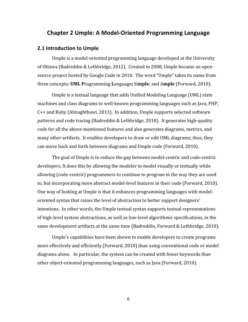
As shown in Figure 2.1, Umple and systems written in Umple can be viewed in
the context of three metamodeling layers. These correspond to the OMG M2, M1 and M0
layers. The top layer (M2) is the Umple metamodel that has been defined in Umple
itself; this represents all the classes in the Umple compiler used to create and compile
models. The complete metamodel can be viewed at http://metamodel.umple.org.
The second layer (M1) is that of Umple models that are instances of the Umple
metamodel, and describe arbitrary software systems. These describe the Umple
elements, classes, associations, attributes, etc. that are part of any Umple program.
The bottom (M0) layer is the elements which are instances of the Umple model
representing the objects, values, states, links, etc. found in a running program
(Almaghthawi, 2013).
2.3 Advantages of Using Umple
Software programmers and developers can benefit from using Umple because it
has several advantages over similar tools.
Umple is written in a textual form that is added to code in languages like Java
and C++. The addition of Umple code also means the program can be viewed as UML
diagrams. Therefore, Umple increases program comprehensibility. Existing tools tend
to separate diagrams from code, and reverse engineering to construct diagrams is often
Figure 2.1: Umple metamodeling architecture by Almaghthawi, 2013
8
only approximate. A UML diagram of an Umple system is guaranteed to be complete
since there is always a direct mapping from the Umple to the UML.
Using a textual form of Umple allows users to develop the essential structures of
a system more quickly than with drawing tools because the text looks like
programming language code and can be typed and edited very rapidly. Moreover, when
using Umple’s web-‐based tool (UmpleOnline) to edit the Umple text, the changes are
immediately reflected as changes to the UML diagram. The user can also edit the UML
diagram itself, and the change appears immediately in the textual code (Lethbridge,
Forward & Badreddin, 2012).
Umple can work with existing libraries in several programming languages such
as Java, C++, Ruby and PHP. Users can extend existing classes even if they cannot see
the source code. Also, the user can write arbitrary code to call APIs of existing libraries,
as well as convert code written in any languages to Umple.
In addition, Umple supports generating readable, clean, and understandable
state-‐of-‐the-‐art code. It also supports the generation of several different high-‐quality
programming languages at the same time by maintaining language-‐independent files
for the models and linking them to language-‐specific code for algorithms.
One of the Umple guiding principles is that it has to be able to implement other
software patterns and other programming idioms besides UML concepts, such as
generating code for a singleton, immutable or delegation pattern. This has the
advantage of increasing the abstraction level of Umple (Lethbridge, Forward &
Badreddin, 2012).
Umple eliminates the need for writing boilerplate code (e.g., for constructs,
patterns, attributes and associations) because the Umple compiler generates such code.
This leads to reducing the number of lines of code to be written in Umple, resulting in a
more readable system so that users can better focus on the logical issues and critical
parts of their code, rather than the low-‐level technical problems. Also, eliminating the
boilerplate code reduces the likelihood of introducing bugs into the system by enabling
the user to write bug-‐free code for complex model constructs such as associations and
9
state machines in a consistent way.
Umple also eliminates the need for a ‘round-‐trip’ process. In Umple, the
generated code should not be edited or changed. If the generated code is not the type of
code the user wants, the user can embed traditional code into the Umple text, or they
can use Umple's aspect-‐oriented capabilities, which act to enforce constraints or change
the semantics of the program. Umple hence eliminates round-‐tripping, although it
supports code-‐to-‐model transformation by converting an existing system to Umple
(this Umplification process is still under development).
Umple bridges the gap between modeling languages and programming
languages. That is, it provides model-‐code duality. One of Umple’s main philosophies is
that it merges code and UML models. Umple allows developers to write a model-‐only
file, a code-‐only file for a target language such as Java or C++, or they can mix a model
with target language code in one file.
Umple provides synchronization between diagrams and corresponding text to
represent the same underlying model, which allows for interchangeable manipulation.
Also, it illustrates the strong relationship between a modeled system and its underlying
implementation (Forward, 2010).
A user can incrementally refactor (umplify) a program in a base language that
will pass through the Umple compiler unchanged by getting rid of complex code (for
constructs like associations, state machines and patterns) and replacing it with simple
Umple code. The user can do this little by little, testing at each step (Lethbridge,
Forward & Badreddin, 2010).
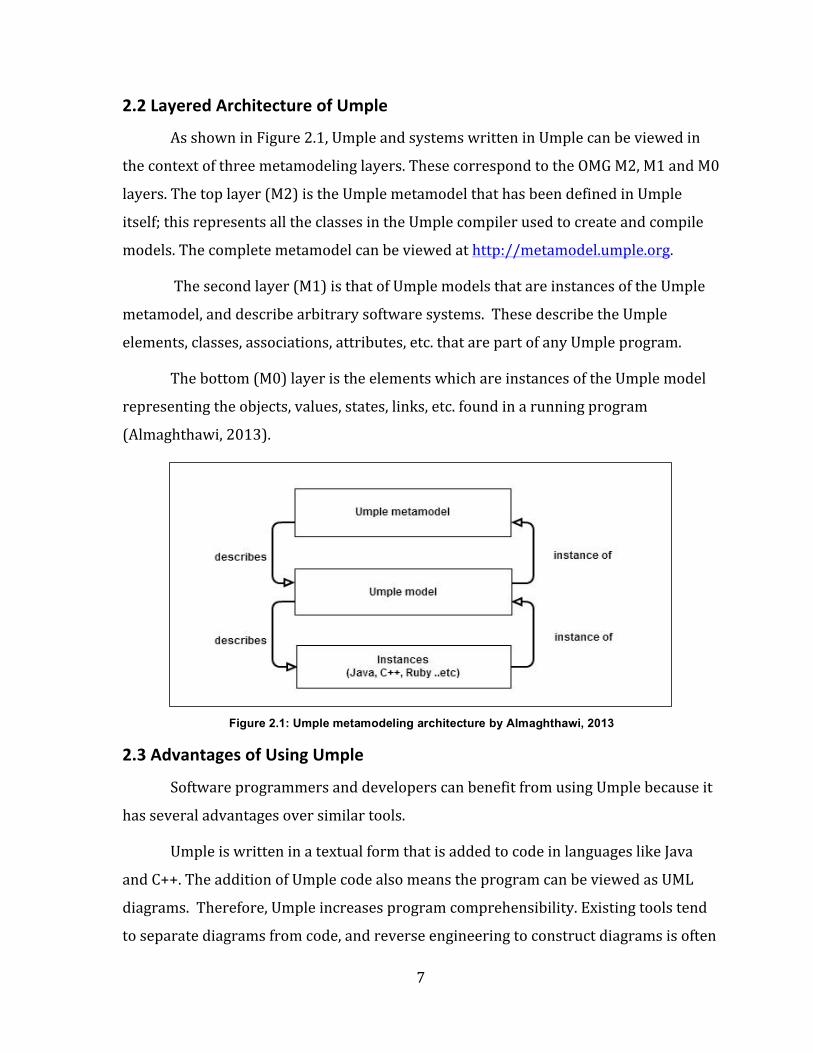
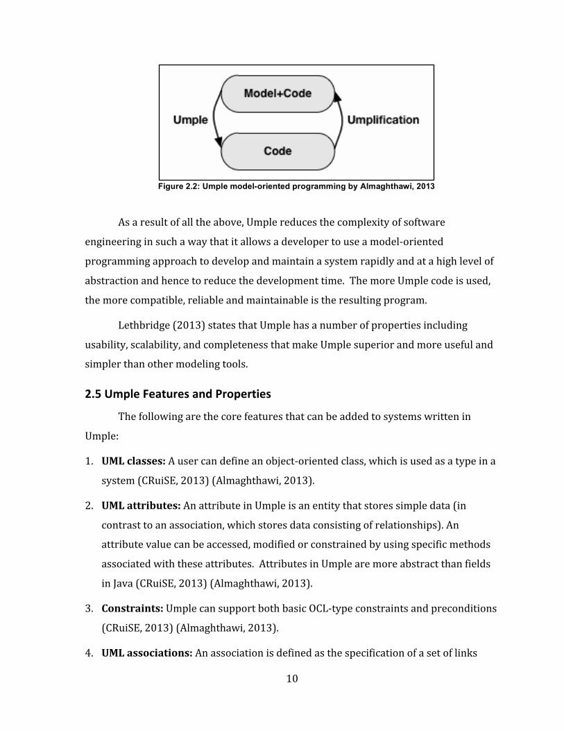
Figure 2.2 shows that model-‐to-‐code transformation is possible with no round-‐
tripping. Code-‐to-‐model transformation is also allowed, which is called “umplification”
(Almaghthawi, 2013). Umplification process is currently developed by Miguel Garzon
(PhD student working on the Umple Project).
10
As a result of all the above, Umple reduces the complexity of software
engineering in such a way that it allows a developer to use a model-‐oriented
programming approach to develop and maintain a system rapidly and at a high level of
abstraction and hence to reduce the development time. The more Umple code is used,
the more compatible, reliable and maintainable is the resulting program.
Lethbridge (2013) states that Umple has a number of properties including
usability, scalability, and completeness that make Umple superior and more useful and
simpler than other modeling tools.
2.5 Umple Features and Properties
The following are the core features that can be added to systems written in
Umple:
1. UML classes: A user can define an object-‐oriented class, which is used as a type in a
system (CRuiSE, 2013) (Almaghthawi, 2013).
2. UML attributes: An attribute in Umple is an entity that stores simple data (in
contrast to an association, which stores data consisting of relationships). An
attribute value can be accessed, modified or constrained by using specific methods
associated with these attributes. Attributes in Umple are more abstract than fields
in Java (CRuiSE, 2013) (Almaghthawi, 2013).
3. Constraints: Umple can support both basic OCL-‐type constraints and preconditions
(CRuiSE, 2013) (Almaghthawi, 2013).
4. UML associations: An association is defined as the specification of a set of links
Figure 2.2: Umple model-oriented programming by Almaghthawi, 2013
11
between classes as a language primitive. It allows for a large amount of code for the
association to be generated in any of the supported programming languages (Java,
C++, PHP, etc.). Umple represents associations in one of two ways: in-‐line (in one of
the associated classes) or independently (outside either class). It generates
specialized code for reflexive associations and association classes (CRuiSE, 2013)
(Almaghthawi, 2013).
5. UML state machines: Umple allows an unlimited number of state machines in a
class, and an unlimited amount of state nesting. It allows guards written in the base
language, as well as entry, exit and transition actions. Do activities trigger
concurrent threads that can execute until an event arrives resulting in termination
of a state. Since state machines are the focus of this thesis, we will discuss them
more extensively later in section 3.1.11.
6. Software patterns: Immutable, delegation and singleton are supported as language
primitives.
7. Base-‐language methods: Umple enables methods written in a base language to be
embedded into the Umple program and passed to the compiler without being
changed or modified while the rest of the code is generated by Umple (Lethbridge,
2013). In fact, separate bodies for the same method can be given for each target
language.
8. Aspect-‐oriented code injection: Umple allows the use of before/after statements
to enforce conditions on attributes, associations, constructors and the components
of a state machine: A user or developer has the ability to inject code before or after
any method such as the event methods of the state machine (as the state machine
event methods are generated automatically from the state machine) (CRuiSE, 2013)
(Almaghthawi, 2013). The purpose of using this technique is that sometimes a user
or a developer wants some code to be executed when processing an event by a state
machine regardless of what state the state machine is in.
9. Mixins as a reuse mechanism: This allows code that is developed independently
to be injected into a set of classes. It also allows a user or a developer to compose a
state machine from many separate files. Since Umple supports that every class can
12
have an unbounded number of state machines where each of them can be defined
independently, an event in one state machine can trigger transitions in one or more
state machines. Also, the actions and guards can be defined independently as
simple functions that can be reused across a number of state machines or across
classes and components (Badreddin, 2010). In addition, the state machine mixins
can be achieved by defining a stand-‐alone state machine and then call the state
machine inside a class.
10. Tracing: Umple supports a tracing language called Model Oriented Tracing
Language (MOTL) that allows tracing and understanding the behavior of the
systems developed in Umple to debug, monitor, and analyze them (Aljamaan et al.,
2014). The advantage of using MOTL is to give a developer the ability to trace
different UML entities using trace directives without making any change to the
generated code (Aljamaan et al., 2014). It is a part of the Umple project that is
developed by Hamoud Aljamaan (PhD student working on Umple Project). In our
thesis, we have been able to benefit from the ability of MOTL to trace different
Umple state machines. It is possible now to trace a whole state machine in Umple
by specifying a trace directive with the name of a state machine which results in
tracing all states of this state machine with any events and transitions (Aljamaan et
al., 2014). In addition, the developer can trace a whole state machine that can be
nested at several levels of depth or trace specific levels of substates. It is possible to
trace different elements of a state machine specifically as a developer determines.
For example, a developer can trace a certain state, transition, event, as well as
specific attributes that can be constrained to occur in a specific state (Aljamaan et
al., 2014).
Umple also supports importing and exporting of code to other forms of UML such
as TextUML and Papyrus XMI (Almaghthawi, 2013).
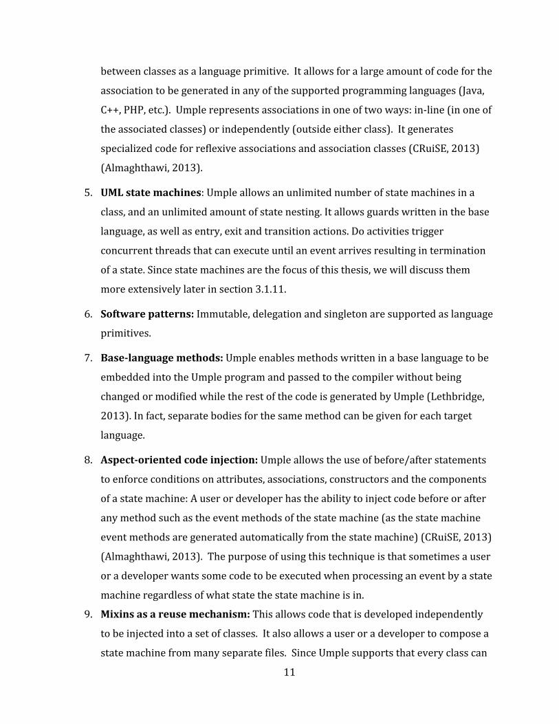
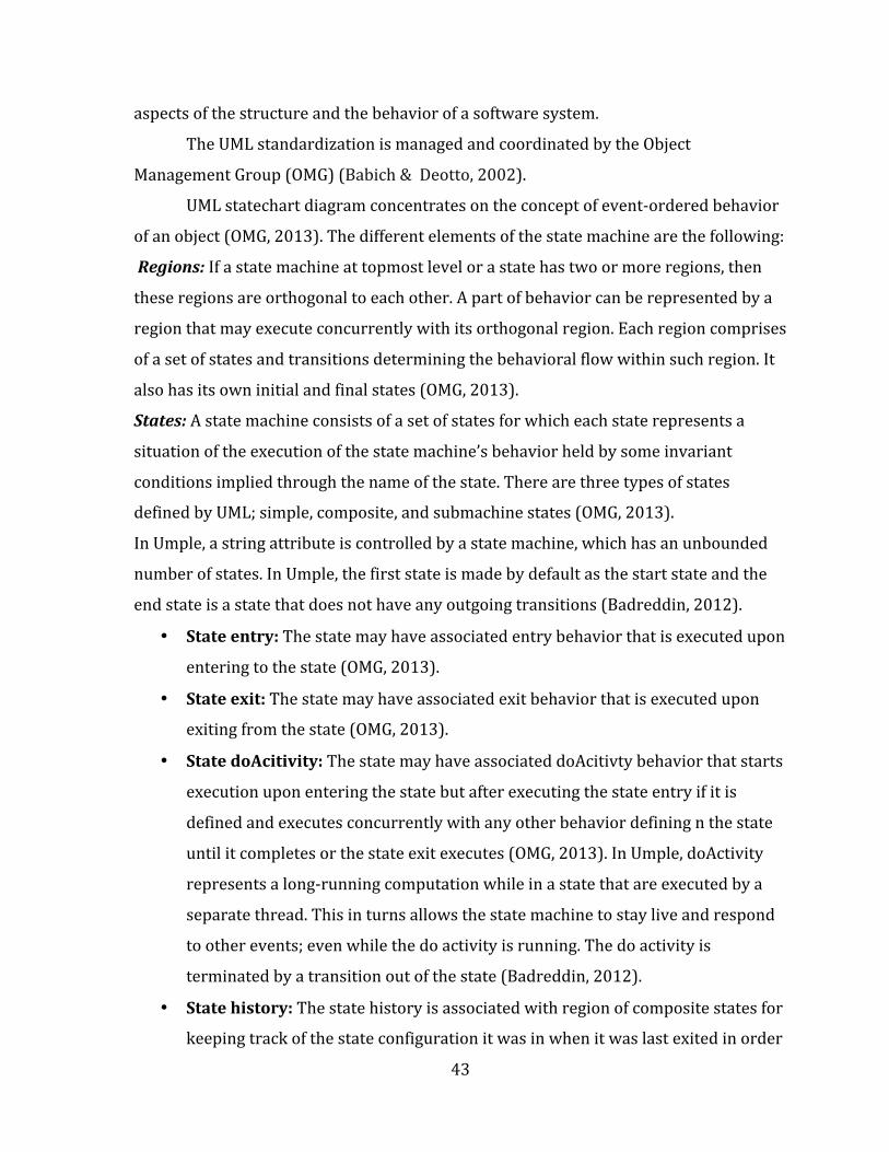
Figure 2.3 gives a small sample of Umple. This shows a state diagram drawn by the
UmpleOnline tool and the corresponding textual Umple form. This state machine is called
‘bulb’ and it has two states: ‘On’ and ‘Off’. The state machine has one transition causing the
state machine to transition from ‘On’ to ‘Off’ if the event ‘push’ is triggered.
13
2.6 Umple Tools
This section gives an overview of the current Umple development tools that are
available to support viewing, editing and compiling Umple files to create an Umple model
or system.
The key Umple tools are UmpleOnline, the command-‐line-‐based compiler, and an
Eclipse Plugin, each of which was created for a specific purpose.
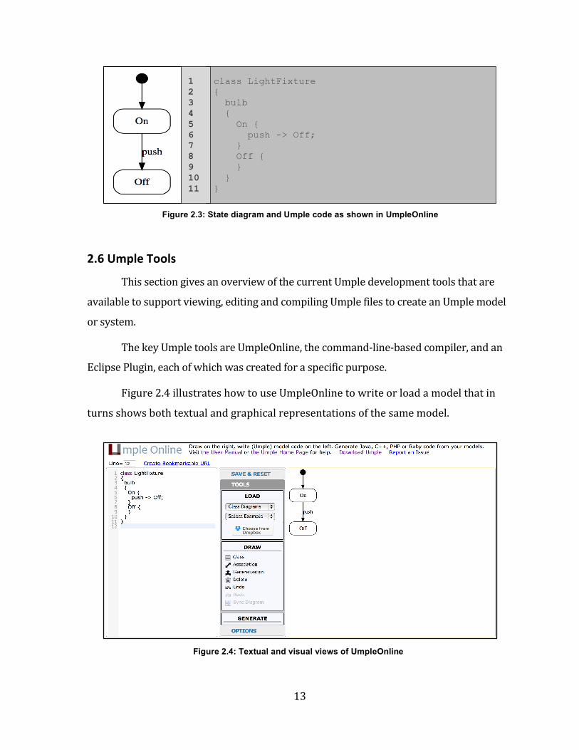
Figure 2.4 illustrates how to use UmpleOnline to write or load a model that in
turns shows both textual and graphical representations of the same model.
Figure 2.4: Textual and visual views of UmpleOnline
class LightFixture { bulb { On { push -> Off; } Off { } } }
Figure 2.3: State diagram and Umple code as shown in UmpleOnline
1 2 3 4 5 6 7 8 9 10 11
14
A description of all three tools is provided below.
2.6.1 Umple Command-‐Line Compiler
The Umple language can always be used from the command line. The Umple
command-‐line compiler is preferred by traditional programmers who can use it to
compile Umple files and generate the target code (Lethbridge, 2013). This tool is
available as a Jar file and requires only an up-‐to-‐date installation of JVM Java 7
(Forward & Lethbridge, 2014).
An Umple file can be compiled using the command line by running this
command:
java -jar umple.jar *.ump
Where * indicates the name of the Umple file and .ump indicates that code is
written in Umple. As in a standard compiler, several files can be specified on the
command line if desired.
Running this command compiles the Umple file and returns a notification
message. If it compiles successfully, the message will be:
*.ump
Success! Processed *.ump.
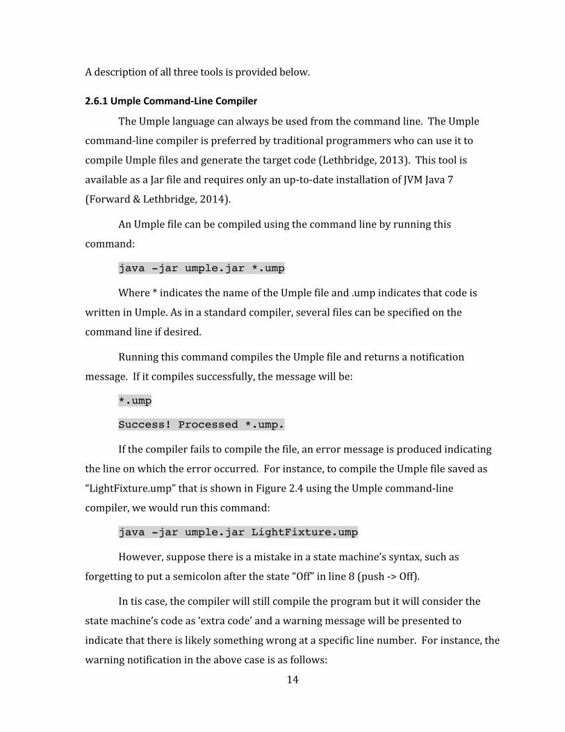
If the compiler fails to compile the file, an error message is produced indicating
the line on which the error occurred. For instance, to compile the Umple file saved as
“LightFixture.ump” that is shown in Figure 2.4 using the Umple command-‐line
compiler, we would run this command:
java -jar umple.jar LightFixture.ump
However, suppose there is a mistake in a state machine’s syntax, such as
forgetting to put a semicolon after the state “Off” in line 8 (push -‐> Off).
In tis case, the compiler will still compile the program but it will consider the
state machine’s code as ‘extra code’ and a warning message will be presented to
indicate that there is likely something wrong at a specific line number. For instance, the
warning notification in the above case is as follows:
15
LightFixture.ump
Warning 1006 on line 8 of file " LightFixture.ump":
State machine syntax could not be processed. It has been
considered as Extra Code
Success! Processed LightFixture.ump.
‘Extra code’ means that Umple believes the construct might be syntax from the
base language (Java, C++ etc.), so it passes it through to the output files.
Suppose the error made is forgetting to put a closing curly bracket ‘}’ at the end
of the program. In that case, the compiler will fail to compile the program and an error
message will be displayed showing the specific line number and file where the error
occurs:
LightFixture.ump
Error 1502 on line 3 of file " LightFixture.ump":
Parsing error: Structure of 'class' invalid
Processed LightFixture.ump.
2.6.2 Umple as an Eclipse Plugin
Umple is available as an Eclipse Plugin that can be used like any other compiler
in Eclipse and can be merged with other Eclipse-‐based modeling tools (Lethbridge,
2013). This gives developers the full power of the Eclipse environment while using
Umple (Lethbridge et al., 2014).
2.6.3 UmpleOnline
UmpleOnline is a web-‐based tool that supports interactive editing of Umple both
graphically and textually, ensuring that UML diagrams are kept synchronized with the
Umple text (CRuiSE, 2013). In addition, it allows generation of high-‐quality code from
Umple directly in a web browser to different programming languages and to various
artifacts supported by Umple.
16
The center pane of UmpleOnline allows users to use Umple to load and save
their models or Umple code (their work). It also enables them to explore various
examples of Umple for models of different systems.
Furthermore, UmpleOnline allows users to type any Umple code into its left
textual pane. Three seconds after the user stops typing in the pane, Umple will
interpret the code and draw a corresponding class diagram in the right-‐hand graphical
pane (Forward & Lethbridge, 2014). The text editor provides “syntax-‐assist,” which
helps users keep their code indented correctly as they type Umple text by highlighting
matching parentheses and Umple keywords.
The right-‐hand graphical pane of UmpleOnline allows users to add a class on the
canvas. They can also add attributes, generalizations, and associations. Several diagram
formats are available including automatically-‐laid-‐out class diagrams, editable class
diagrams, and automatically-‐laid-‐out state diagrams.
The bottom pane of UmpleOnline has a button to generate code and many other
types of output. It shows the errors and warnings that may appear at the bottom of the
page as users edit their text or diagrams (Almaghthawi, 2013).
UmpleOnline was created for several purposes. It is an effective tool used for
educational purposes. Educators and students are not required to install UmpleOnline;
they can access it if they have a browser and an Internet connection. In addition, they can
install a local version of UmpleOnline and manipulate Umple files on their computers
through a web browser (Almaghthawi, 2013). It has a variety of examples of complex
models for different systems. In addition, they can create their own examples and
models, save them on the server and then reload them later using bookmarks
(Almaghthawi, 2013). Because of these features, it is recommended that software
educators use UmpleOnline as a tool for teaching and demonstrating various UML
design alternatives, and for showing the implication those designs have on the
generated code of those alternatives (Forward, 2010).
In addition, UmpleOnline is considered to be a good demonstration tool. Once a
model is created using UmpleOnline, one can see a view of both the visual and textual
17
representations of the same model (Forward, 2010). It can also be used to explore ideas
quickly, giving the developer the ability to create rapidly and simulate basic models
(Forward, 2010). A developer can also create a complicated model of a real case study
using UmpleOnline, and initiate small projects (Lethbridge, 2013). Besides,
UmpleOnline is an excellent tool for preparing professional-‐looking diagrams ready for
publication (Forward & Lethbridge, 2014).
2.7 Umple Architecture
The Umple compiler acts like any other programming language compiler; it is
tested and built in the same manner. In fact, the Umple compiler was written in Java
and then rewritten in Umple itself (Forward, 2010). There are few tools that build their
own compilers using their own languages; one example is the Pascal compiler, which
since the mid-‐1970 has been written in Pascal (Cantu, 2008). In 1962, Hart and MIT
developed the first self-‐hosting compiler for Lisp in Lisp itself (Hart & Levin, 1962).
Writing a compiler in the same language that is developed shows that this
language can provide utilities that may not be found in the “base” language of the
compiler and these features are well-‐suited for the compiler. For instance, most
behaviors can be implemented using the abstract level of the Umple language where
UML constructs can be used as well as other patterns, etc. It can be much easier to
maintain the compiler when the same language is properly used demonstrating the
usefulness of the tool. Moreover, writing the Umple compiler in itself helps the
developer to customize and extend the language using high-‐level abstraction
constructs.
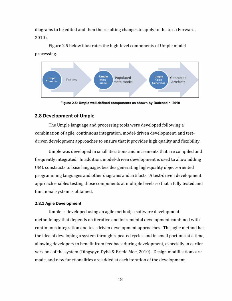
The Umple compiler consists of several well-‐defined internal components
including an Umple parser, which is the analyzer that helps the Umple compiler to
parse the input Umple code into tokens, the Umple metamodel classes, which are the
internal representation of Umple in which the tokens are used to populate and generate
instances of the Umple metamodel from the parse tree, as well as several code
generators used to generate various target base languages such as java, C++, PHP, and
Ruby. Also, model-‐to-‐model transformation engines are used for generating the models
of the systems built using Umple, and a synchronization engine that allows the
18
diagrams to be edited and then the resulting changes to apply to the text (Forward,
2010).
Figure 2.5 below illustrates the high-‐level components of Umple model
processing.
2.8 Development of Umple
The Umple language and processing tools were developed following a
combination of agile, continuous integration, model-‐driven development, and test-‐
driven development approaches to ensure that it provides high quality and flexibility.
Umple was developed in small iterations and increments that are compiled and
frequently integrated. In addition, model-‐driven development is used to allow adding
UML constructs to base languages besides generating high-‐quality object-‐oriented
programming languages and other diagrams and artifacts. A test-‐driven development
approach enables testing those components at multiple levels so that a fully tested and
functional system is obtained.
2.8.1 Agile Development
Umple is developed using an agile method; a software development
methodology that depends on iterative and incremental development combined with
continuous integration and test-‐driven development approaches. The agile method has
the idea of developing a system through repeated cycles and in small portions at a time,
allowing developers to benefit from feedback during development, especially in earlier
versions of the system (Dingsøyr, Dybå & Brede Moe, 2010). Design modifications are
made, and new functionalities are added at each iteration of the development.
Figure 2.5: Umple well-defined components as shown by Badreddin, 2010
19
2.8.1.1 Agile Philosophy
The agile method is adaptive rather than predictive which means that the agile
approach allows for a quick adapting to changes in requirements, and solutions evolve
across collaboration between teams (Bakal, Althouse & Verma, 2012). It is also people-‐
oriented rather than process-‐oriented where the role of the process is to support the
development teams in their work not building their skills (Bakal, Althouse & Verma,
2012). In addition, the agile development method is based on an iterative approach in
which the development tasks are broken in small portions with minimal planning. Each
development task is allocated to a short timeframe called an iteration or sprint, and
each iteration involves working in all stages: requirement analysis, design, coding, unit
testing, and acceptance testing. The testing in an agile manner is usually done in
parallel with coding or starting in early iterations of development life cycle, not in the
last phase of the development life cycle as in the waterfall manner. In contrast, the
waterfall model follows a sequential design process in which a separate testing phase is
done upon the completion of the implementation phase (Dingsøyr, Dybå & Brede Moe,
2010).
In addition, the agile development methodology is an incremental approach in
which each rapid iteration results in producing small software release (Dingsøyr, Dybå
& Brede Moe, 2010).
The aim of the agile development methods is to enhance the quality of the
system that can be achieved by dividing the development tasks into small units. So the
team can produce frequent builds and perform intensive testing during each iteration
which results in detecting and fixing bugs in a rapid manner. Therefore, the agile
method focuses on high-‐quality development, testing, and collaboration between teams
(Dingsøyr, Dybå & Brede Moe, 2010).
Continuous integration and test-‐driven development are two agile practices and
tools that cover various areas such as requirements, design, modeling, coding, testing,
etc. are used to improve the quality of systems and enhance the system agility (Bakal,
Althouse & Verma, 2012).
20
2.8.1.2 Advantages of Agile Methodology
It reduces the overall risk and allow for rapid and flexible response to changes,
which means that it makes it possible to add new features or implement new changes
to the system because of the frequency of new increments produced. It also encourages
teams to have face-‐to-‐face communication to discuss progress and get rapid feedback of
what they have done, what they are doing, and what they will do in the future. Also,
they discuss the features to be newly added or removed and the changes to be
implemented based on changing requirements (Dingsøyr, Dybå & Brede Moe, 2010).
Further, the methodology of agile development results in a high-‐quality system
with minimal bugs and defects because the system is tested intensively during the
iterations of the development life cycle, which is achieved in least possible time. The
agile method is more about coding rather than documentation (Dingsøyr, Dybå & Brede
Moe, 2010).
2.8.2 Continuous Integration
Continuous Integration (CI) is a software development practice created for agile
development that requires members of the team to integrate their changes to a larger
code base frequently, often multiple integrations per day. These integrations are then
verified through an automated build and testing to detect integration errors (Bakal,
Althouse & Verma, 2012).
The goal of continuous integration is to reduce the risk of having an extended
and difficult integration. This helps to get rapid feedback as the automated build for
verifying the integrations helps in detecting integration errors as quickly as possible so
that, if a defect is detected in the code base, it can be rapidly identified and corrected.
The detecting of defects early in development leads to easily resolution of smaller and
less complex defects (Rouse, 2008). Therefore, continuous integration helps reduce the
problems of integration and enables development team to develop cohesive software
more quickly (Bakal, Althouse & Verma, 2012).
2.8.3 Model-‐Driven Development (MDD) Methodology
Model-‐Driven Development (MDD) is an approach in which models are used as
21
specifications of software system in which the essential aspects of software are
expressed. The models are then transformed in order to get corresponding source
code. The transformation of the models constitutes the core of software development
(Beydeda & Book, 2005). For example, a model transformation can facilitate the
process that converts between different views of the system at an equivalent level of
abstraction, or converts models between levels of abstraction, usually from a more
abstract to less abstract view by adding more details supplied by the transformation
rules (Beydeda & Book, 2005). The word ‘driven’ in MDD indicates that this approach
enables models to be given a central and active role because they are at least as
important as source code (Völter et al., 2013).
MDD is a less precise but common name for the discipline called model-‐driven
software development (MDSD) (Völter et al., 2013).
Mellor et al. (2003) point out that the main idea behind MDD is to model a
system at several layers of abstractions and from different views (as cited in Parviainen
et al., 2009, p. 10). The models that are created for the system become the main
artifacts of software development. By using generators or executing the created models
at run-‐time, these models are transformed into running systems.
Models, modeling, and model-‐driven architecture (MDA) are considered the
three basic concepts of the MDD approaches (Beydeda & Book, 2005).
Creating models for a software system is useful to identify a problem domain
and design a solution in the solution domain. MDD models are abstract and formal at
the same time. They have an exact meaning like programming code (Völter et al.,
2013).
In addition, identifying relationships between the created models offers a
network of dependencies that mark the process in which a solution is created, and also
it assists in recognizing the implications of modifications at any point in that process
(Beydeda & Book, 2005).
In MDD, the created models do not create documentation for software but they
are considered to be part of the software, and they are equal to source code because of
22
the automation of their implementation (Völter et al., 2013). Moreover, defining a set
of rules is required in order to automate many steps needed to transform one model
representation to another, to trace between model elements, and to analyze essential
features of the models (Beydeda & Book, 2005).
MDD targets finding domain-‐specific abstractions and enables accessing them
through formal modeling (Völter et al., 2013). Völter et al. (2013) illustrate that there
are three requirements that are required to be achieved in order to apply the "domain-‐
specific model' concept; they are:
– Domain-‐specific languages are needed to enable the actual defining of models.
– Model-‐to-‐code transformation languages are needed.
– In order to run the transformations to generate executable code on various
platforms, compilers, generators or transformers are needed.
By using models to represent the software and visualize the code and the
problem domain, MDD intends to speed up the software development and makes it
more cost efficient. MacDonald et al. (2005) state that MDD also aims at separating
implementation technology from the business logic of the program (as cited in
Parviainen et al., 2009, p. 10).
MDD implies more precise and clearer views of aspects while dealing with
software development paradigm. It gives a clear description of the meaning of models,
the separation of the domain-‐specific and technical implementation, the relationship
between design and implementation, round-‐trip problems, architecture and generation,
versioning and tests that if it is applied correctly, it will make the work of the developer
much easier, and it will help avoid redundant code and improve software quality by
using formalized structures (Völter et al., 2013).
According to Duby (2003), Object Management Group's (OMG) Model-‐Driven
Architecture (MDA) is referred as software systems modeling, and it is a well-‐known
example and standardization initiative of OMG focusing on MDD (as cited in Parviainen
et al., 2009, p. 10). OMG works as an industry-‐driven consortium to develop standards
for the implementation of MDD. MDA depends on a set of emerging standards to define
23
a set of models, notations and transformation rules (Beydeda & Book, 2005). The idea
behind developing MDA was to allow the specification of system functionality (i.e. the
processing and logic of the system) to be separated from the specification of its
implementation technology. It then enables developers to focus on solving the problem
rather than the dealing with the details of the implementation technology (as cited in
Parviainen et al., 2009, p. 10). MDA as a way of modeling has several advantages
because it enhances the quality, efficiency, and predictability of software development.
France & Rumpe (2007) state that MDA demonstrates the modeling of the
system from three viewpoints (as cited in Parviainen et al., 2009, p. 11). The
computation independent viewpoint is about the required features of the system, as
well as the environment in which it operates. It results in computation-‐independent
models (CIM). The platform independent viewpoint is concerned with the features of
the system that are fixed and do not change as the system is used on different
platforms. It specifies what the system does, and it results in platform-‐independent
models (PIM). The integration of PIMs with the platform-‐specific details in the
platform-‐specific viewpoint results in platform-‐specific models (PSM) that describe
how the system is implemented.
2.8.3.1 Advantages of Model-‐Driven Development (MDD)
Mellor et al. (2003) argue that models can be used to increase productivity
because building a graphical model using Unified Modeling Language (UML) is cheaper
than writing functional code in Java, for example; however, using models may raise the
degree of obstacles (as cited in Parviainen et al., 2009, p. 11). The list below shows that
adopting MDD has several advantages.
According to Völter et al. (2013), MDD enhances the quality of software and
helps improve the manageability of software complexity.
Regarding Umple, it supports MDD by allowing the developer to present and
maintain a complex system as a model either textually or graphically, and then generate
high-‐quality code from that system (Lethbridge, 2013).
24
2.8.4 Test-‐Driven Development (TDD) Methodology
Test-‐driven development (TDD) is an agile software development process that
consists of a set of short development cycles or iterations (Patrick, 2006). It has been
widely used within the agile process. It is a well-‐known development process used for
open-‐source software projects; particularly ones concerned with adaptation of agile
principles for continuous integrations of the system development which results in more
manageable and understandable code (McConnell, 2014). This process is performed in
short, and rapid iterations (Janzen & Saiedian, 2005).
The TDD approach results in enhancing the quality of the design and makes it
easier to work with it in the future. In fact, TDD helps drive the design specification as
well as directly validating it (Ambler, 2012).
The TDD process requires writing a set of automated tests, which, when first
written, are expected to fail. The system is then changed so they pass. The automated
tests become an aspect of the system’s specification and a primary component of the
system documentation; they are executed with every subsequent system change,
providing rapid feedback about any bugs or unexpected side-‐effects of subsequent
changes to the system. (Janzen & Saiedian, 2005).
Test-‐driven development was developed initially by Kent Beck (2003), and it has
become widely accepted as a methodology in the software development community in
combination with agile process models and the Extreme Programming (XP). Both agile
process and test-‐driven development (TDD) are considered as basic methods working
on iterative, incremental and evolutionary basis in the modeling process. In 2002, Beck
claimed that following TDD for developing a system leads to simpler designs and
increases the level of confidence.
An automated unit testing framework for Java called JUnit was developed by
Erich Gamma and Kent Beck to implement TDD with Java. Implementing JUnit-‐like
frameworks for various languages leads to creating a family of frameworks called xUnit,
which enables programmers to write numbers of automated unit tests in order to
initialize, execute, and make assertions about the code needed to be tested (Janzen &
25
Saiedian, 2005). Writing xUnit automated tests in the same language as the code under
test results in allowing these tests to serve as first-‐class clients of the code, while the
tests themselves actually serve as specification and documentation for the code. The
test order does not matter because individual tests are written to be independent of
one another. In addition, xUnit frameworks allow programmers to report the total
number of successes and failures (Janzen & Saiedian, 2005).
According to Beck (2002), there are two main rules driven from adopting and
using the test-‐driven development process:
1. Writing new code to enhance the functionality of the system only if an
automated test written for this code has failed, and
2. Refactoring both the production code and test code to remove any duplication
that may occur (Beck, 2002).
These above two rules drives the TDD mantra that is "Red-‐Green-‐Refactor." The
“Red Green Refactor” mantra refers to a process that indicates that using the TDD
methodology enables focusing on small steps for writing software. It ensures that the
process ends up with high-‐level productive and confident system by enhancing the
production code (Boydens, Cordemans & Steegmans, 2010).
The development micro-‐cycle of TDD is visually shown in figure below:
Figure 2.6: Test-driven development (TDD) cycle: Red-Green-Refactor by Boydens, Cordemans & Steegmans, 2010
26
Figure 2.7 illustrates steps that are driven by the above principal rules of TDD:
2.8.4.1 Benefits of Test-‐Driven Development (TDD) Methodology
TDD is suitable for developing large systems where there are large numbers of
developers working on developing and implementing the systems. This results in a
large number of functional code lines and test code lines that would be running in a
short time (Forward, Badreddin, Lethbridge & Solano, 2012).
In fact, TDD makes it easier for new developers to contribute to the software.
This process supports adding a minimum code that is enough to make tests pass rather
than writing a large number of lines for functional code which as a result can help
detecting and resolving defects whenever they exist (Forward, Badreddin, Lethbridge &
Solano, 2012).
In addition, TDD leads to improved code quality by enabling continuous
regression testing (Beck, 2003). That is, automated unit tests will be run when the code
is enhanced or maintained to detect and identify any new defects, as well as to control
the uniformity of software releases (Beck, 2003).
Figure 2.7: A graphical representation of the necessary steps for the test-driven development (TDD) cycle, using basic flowchart
27
To sum up, following TDD for developing and implementing software leads to
if (name.compareTo("getState") != 0 && name.compareTo("getOwner") !=
0) {
_ transition_map.put(name, transitions[i]);
}
}
} catch (Exception ex) {}
}
Finally, a transition method is added to queue up a transition only if it detects
the call outside a transition, and then dequeue a transition and execute it (Rapp, 2014)
as follows: private synchronized void transition(String trans_name) {
// Add the transition to the queue.
transition_queue.add(trans_name);
// Only if a transition is not in progress should a transition be
issued.
if (_fsm.isInTransition() == false) {
String name;
Method transition;
Object[] args = new Object[0];
while (_transition_queue.isEmpty() == false) {
name = (String) _transition_queue.remove(0);
transition = (Method) _transition_map.get(name);
try {
transition.invoke(_fsm, args);
} catch (Exception ex)
{
// Handle exception.
51
}
}
}
return;
}
In Umple, we define a queued state machine (QSM) which is a state machine
that has a queue in which events are injected to be processed for later execution. The
Java generated code from QSM is described in Chapter 4.
Default transitions:
In addition, SMC deals with a case of unexpected events by defining “Default”
transitions that are placed in a state to back up all transitions (Rapp, 2014). These
transitions enable objects to handle and recover unexpected events and continue
execution normally. The “Default” transition may have guards, and it may not have
transition arguments (Rapp, 2014).
Moreover, if a state receives a transition that is not defined in that state, a
special state named ‘Default” can be defined. This special state contains transitions that
may have guards and argument features. If a user does not define a Default state or a
Default transition, and there is no relevant transitions defined in a state machine when
a cetain event occurs, SMC will throw a “Transition Undefined” exception (Rapp, 2014).
In Umple, we have a special transition named ‘unspecified’ to handle unexpected
events. More information about this special transition is presented in Chapter 5.
Transition Arguments:
Furthermore, SMC enables defining argument lists for state machine transitions.
The transitions can receive an argument list that is typically used in the guard
conditions or possibly in transition actions (Rapp, 2014). When the same transition is
defined with multiple guards and different argument lists are used, SMC will result in
incorrectly generated code (Rapp, 2014). In Umple, a transition’s arguments are also
supported.
52
3.6.2 Sparx Systems Enterprise Architect (EA)
Enterprise Architect has been developed by Sparx Systems to specify, design,
construct and document software systems projects (Sparx, 2014). It is a visual platform
built on UML 2.5 specifications to be used for various generalized modeling purposes. It
includes a set of features and capabilities that cover all aspects of development (Sparx,
2014). Sparx Systems has developed EA for 15 years (Sparx, 2014). It is intended for a
broad range of industries in 160 countries.
EA supports generating and reverse engineering of source code for state
machines and other models in programming languages such as Java, C, and C++ (Sparx,
2014). The UML modeling in EA supports and depends on code engineering; that is, a
user can generate code from a model, and create and update the model from code. It
also allows for debugging, compiling and visualizing executable code generated from
the model (i.e. it converts the actual code execution and calls into visual diagrams). In
addition, the EA tool allows for round-‐trip and synchronization of code in various
programming language; therefore, code generation templates provided by EA enable
customizing generated source code(Sparx, 2014).
Enterprise Architect supports modeling UML state machines that are based on
Harel State Charts (Sparx, 2014). In EA, a state machine demonstrates the movement of
an element (a Class) between states. It also classifies the behavior of this element
depending on transition triggers and conditioning guards. The state machine diagrams
include a set of elements that a user can use for modeling the behavior of dynamic
systems. State machine diagrams elements include states, initial states, final states,
history states, decision points, junctions, entry points, exit points, terminations, and
forks/joins (Sparx, 2014). Also, connectors used for state machine diagrams are
transitions and object flows. The transition defines the logical movement from a state
to the next state in a state machine (Sparx, 2014). It can have a guard, effect, or trigger
(event). The trigger can be of the following four types: Call, Change, Signal, or Time.
In addition to those state machine diagram elements, it is possible to add
composite states and regions to a state machine diagrams by first creating a composite
state element and then subdividing the element with regions.
53
Enterprise Architect not only supports generating, compiling and executing Java
code from State Machines, but also it supports simulating State Machines in visual
models during execution (Sparx, 2014).
EA does not generate Java code for queued transitions explicitly but while the
execution of a simulation of a state machine, the triggers are queued to the end of the
list of the simulation events. The status of a trigger can be a used trigger (i.e. fired), a
lost trigger (i.e. fired but has no effects), a signaled trigger (i.e. fired and consumed by
one or more transitions), or not signaled trigger (i.e. have not fired yet). The EA tool
also enables a user to add parameter values to a signal trigger each time the simulation
fires the trigger (Sparx, 2014).
3.6.3 Real-‐Time Developer Studio (RTDS)
PragmaDev Real Time Developer Studio (RTDS) = supports both SDL and SDL-‐
RT. It is used to model and develop real-‐time and embedded software (Pragmadev: Real
time developer studio, 2014).
RTDS can be used for all stages of the development cycle. It provides users with
a graphical interface that enables them to manage projects, design models, simulate the
models, and generate code from the models (Pragmadev: Real time developer studio,
2014).
RTDS supports the SDL standard of the International Telecommunication Union-‐
Telecommunication Standardization Sector (ITU-‐T), and also supports the SDL-‐RT
standard, which is a mix of the SDL standard, UML, and the C language (Pragmadev:
Real time developer studio, 2014).
SDL contains an action language with an execution semantics in addition to its
graphical notations. For this reason, SDL is considered as a formal language and its
models are executable. However, SDL-‐RT is semi-‐formal because it combines the SDL
standard with C code (Pragmadev: Real time developer studio, 2014).
RTDS tool allows development of the requirements, structural and behavioral
models and designs; it also supports model checking capabilities, traceability
information, code generation, and testing (Pragmadev: Real time developer studio,
2014).
54
RTDS supports generating code for the whole system or sub-‐parts of the system
such as a process, a task, or a block in order to compile and execute it. The generated
code can be documented for further customization (Pragmadev: Real time developer
studio, 2014).
RTDS only enables generating C or C++ code from SDL models; it does not
support generating Java code from these models. Thus, the comparison of the generated
code of the SDL models with the generated code of Umple queued state machines is not
applicable at this level. This is because our work only enables generating Java code for
queued state machines in Umple. However, the other team members in our group are
working on generating C++ from the queued state machines (Pragmadev: Real time
developer studio, 2014).
3.7 Handling Unspecified Reception in Specification Languages
To handle Unspecified Reception errors, the following ways can be used:
• Input is dropped and ignored which is the semantics of SDL and original Umple
state machines. In certain designs, this can be a valid choice. For example if a
state machine is modeling user interaction, and certain buttons are to be ignored
in certain states, then it is reasonable to just drop events that correspond to
ignored button presses.
• Complete behavior for all inputs by adding “error” state and transition
corresponding to the inputs that were non specified in the original specification
will lead to this error state. In an error state, all inputs will lead back to this
error state. This is what we have done in Umple with the addition of the
‘unspecified’ keyword.
• Queue models defined for communicating subsystems or components.
Bochmann (2013) listed three queuing models in which the definition of the
properties of the composed system depends on: a single input queue for each
component, multiple queues, one for each source component, and an input pool.
The message transmission can be reliable or unreliable and the messages can be
received in order as they are sent or not. For the third model that is input is
deferred and placed in a buffer pool, -‐ inputs are left in the buffer pool and will
55
not be consumed in this state of the specified component. When the state
changed appropriately, they can be consumed. The SAVE operator in SDL,
Deferred Event in UML, and General Message Pool are used for this purpose. In
Umple we have added the concept of a pooled state machine. Details of these are
described in the next subsection.
3.7.1 Original Semantic of Umple State Machines in Case of Unspecified Reception
In original semantics of Umple state machines, the default behavior for handling
unspecified reception error is to return false and ignore an unexpected event if the
current state does not respond to it.
In addition, in the case of extended semantics of Umple state machines,
unspecified reception occurs when a message exists at the head of queue and there is a
set of reception transitions but the message in the queue is different from the messages
expected by the reception transition.
3.7.2 Save Operator in SDL and Deferred Event in UML
In current SDL semantics, each state machine is assumed to have a single input
queue where received messages from different sources are stored. If an unspecified
reception event occurs, a message at the head of a queue will be dropped.
SDL supports the SAVE operator which is concerned with non-‐ordered signal
reception. A SAVE operator in SDL matches the deferred event of UML (Selic &
Rumbaugh, 1999). The main idea of SAVE operator is to postpone the consumption of a
specified signal for future processing until the following transition is executed (Babich
& Deotto, 2002). In the SDL grammar, the SAVE operator specifies a set of identifiers for
signals and remote procedures whose instances are not related to the process in a state
to which save is attached and they have to be saved for future processing (Babich &
Deotto, 2002).
The SAVE operator changes the order of signal consumption because it saves the
events that cannot be triggered in a state where this operator is defined (Hogrefe,
2013). In addition, the SDL SAVE construct is added for each signal that may arrive in
the input queue earlier that expected to prevent deadlocks in the SDL specifications
(Hogrefe, 2013).
56
Unspecified reception in UML is an unexpected event reception which is
recognized as a semantic variation point. The default behavior in UML when
unspecified reception occurs is to discard this event if the deferred construct is not
defined (Lilius & Paltor, 1999). However, in UML state machines, there is a special
mechanism for deferring events in states (Selic & Rumbaugh, 1999). This can be
achieved by including a clause ‘deferred / {event list}’ in a state (Selic & Rumbaugh,
1999). This advanced constructor is used to solve the problem: when an event usually
does not enable any transitions, it is kept waiting until the next state, meaning that the
transition selection mechanism does not discard this event in this case. In the UML
standard, a set of deferrable events can be attached to a state. So if the event that does
not enable any transitions occurs, it is pushed into the deferrable list and once the
system move to a next state, this event will be dispatched and processed if it enables
any transitions (Lilius & Paltor, 1999). Upon entry to such state, the UML state machine
will automatically recall any saved event(s) that are no longer deferred and process
them as if they have just arrived (Selic & Rumbaugh, 1999).
57
Chapter 4: Queued State Machines (QSM) and Pooled State
Machine (PSM) in Umple
4.1 Enhancements to Umple State Machines
We extend the semantics of Umple state machines to add queued state machines
(QSM) and pooled state machines (PSM).
These mechanisms can be used for communicating FSMs (CFSMs), but can also
be useful when there is only one state machine, with other code triggering events.
A queued state machine (QSM) in Umple is a state machine that works in a
multithreaded environment and supports an event queue. The code that creates events
will add each event to a queue. A separate thread processes the events in the queue in
first-‐in-‐first-‐out (FIFO) order and performs any actions and necessary state changes.
A pooled state machine (PSM) in Umple works in the same way as the queued
state machine (QSM) except in the way it deals with the case of unspecified reception.
As with QSMs calls to event methods of PSMs return immediately. But the handling of
events is not done strictly in FIFO order as in QSMs, but in the order in which the events
are required by the transitions from the current state. In other words, if an event is at
the front of the queue, but the current state does not have a corresponding transition,
then the next event in the queue is considered (and so on).
QSM and PSM in Umple can be used in the case when we have only one state
machine that can operate normally while the other thread triggers events. In other
words, one thread will take care of implementing the behavior of the state machine
while the other thread handles event triggering. In addition, QSM and PSM can be used
for communicating finite state machines (CFSMs). They perform thread safe operations.
They can provide better handling of signals and asynchronous communication
semantics to simplify communication between state machines interacting with each
other by asynchronous calls of events and passing of messages.
The main features of the queued and pooled state machines are:
58
1. Adding the events to the queue/pool as they are called.
2. In QSM, processing the events in the same order as they are received (i.e. in FIFO
order).
3. The event-‐processor thread processes the events until there are none left in the
queue/pool (or none in the pool that can be handled), and then it waits for the
next event to arrive.
4. If an event occurs in a QSM that does not match any event in the current state
(unspecified reception), and there is no transition labeled ‘unspecified’, then the
event is taken off the queue and ignored (i.e. it is not processed). If an
‘unspecified’ pseudo-‐event exists in the current state then this transition is taken
instead.
Queued and pooled state machines extend the original semantics of state
machines in Umple, in the following called Basic state machines, which is considered to
be appropriate mostly for simple applications. Basic state machines in Umple work in a
single thread, they process events immediately as they are received. When an event
occurs and there is no state anywhere in the (queued, pooled or basic) state machine
that accepts it, the compiler will detect this event and indicate to the user that this
symbol cannot be found.
When the state machine's event occurs, the state machine code continues in the
same thread as the caller. A problem occurs when there are two machines and the
second machine creates an event for the first machine in a transition that is triggered
by the first machine. As shown in Figure 4.1, there are two method calls active on the
same machine at the same time (which is bad programming practice). In fact, during
the transition of SM1 triggered by b, the transition of SM2 is called, which in turn calls
the transition c of SM1 (which has not yet completed its b transition) – two transitions
are active on SM1 at the same time.
59
a
c
b
y1, y2
SM1
c/y1 c/y2
b/SM2.a S11 S12
S13 S14
SM2
a/SM1.c
S21
S22
Figure 4.1: Example of the state machines in which two event method calls active on the same machine at the same time
To illustrate the differences between the basic and extended semantics of Umple
state machines, an example of two state machines is shown in Figure 4.1. Two
questions needed to be addressed to distinguish between the actual and expected
behaviors of those two machines, which are:
“What happens when an input event ‘b’ is processed? What output to the
environment would have been produced and which state would the machine (SM1) be
after an input event ‘b’ has been completely processed?”
The expected behaviors of both machines are as follows. The first machines SM1
is initially in state (s11) and the second machine SM2 is initially in state (s12). When an
input event ‘b’ occurs, the action of this transition is executed: an event ‘a’ of the state
machine SM2 is called and the event ‘b’ is processed; the machine SM1 moves from
state (s11) to state (s12). Then the event ‘a’ of the machine SM2 is processed. The
action of this transition includes calling the event ‘c’ of the machine SM1. It then moves
the machine SM2 from state (s21) to state (s22). Then, the event ‘c’ is the processed.
The machine SM1 transitions to state (s13) and produces the output ‘y1’ to the
environment.
In Umple basic state machine, Umple uses procedure call semantics to process
input events. That means each transition of the state machine is realized as a method
that is called when the event occurs.
Implementing the above example in Umple basic state machine causes the
transitions b and c to be active at the same time. This is due to the fact that Umple
implements the basic state machines in a single thread environment.
60
The actual behaviors of the Umple basic state machines: SM1 and SM2 are not as
expected. During the call of the ‘b’ transition, the method ‘a’ is called on the same object;
that is, there are two processes executing in the same object simultaneously, the
waiting of the ‘b’ method, and the execution of the ‘a’ method. Thus, the actual
behaviors of SM1 and SM2 are as follows. When the event ‘b’ occurs, the method ‘a’ is
called, the event method ‘c’ is called and SM2 moves to (s22). When the method ‘c’ is
called, the machine SM1 is still in state (s11) because the method ‘b’ is still executing.
Thus, the method ‘c’ is called; the machine SM1 moves from (s11) to (s14), and the ‘y2’
output is produced to the environment. The final outputs indicate that there is a
problem in the implementation of these state machines SM1 and SM2 in Figure 4.2.
The proposed solution for this problem is to use Umple Queued State Machines
(QSM) because they are implemented in a multithreaded environment, which will work
for this kind of concurrency.
The actual behaviors of SM1 and SM2 when using QSMs are shown in Figure 4.3,
4.4, 4.5, and 4.6. When the input event ‘b’ occurs, the event ‘a’ is injected in the queue
until the event ‘b’ is completely processed. The process transitions SM1 from (s11) to
(s12). Then, the event ‘a’ is taken off the queue (it is consumed). The process of the
event ‘a’ performs calling of an event ‘c’. The event ‘c’ is injected in the queue. After the
event ‘a’ is completely processed to move SM2 from (s21) to (s22), the event ‘c’ is taken
off the queue (it is consumed). It moves SM1 from (s12) to (s13) and produces ‘y1’ to
the environment. Figure 4.6 shows the final outputs of the implementation of queued
SM1 and queued SM2.
a
c
b
y2
SM1
c/y1 c/y2
b/SM2.a S11 S12
S13 S14
SM2
a/SM1.c
S21
S22
Figure 4.2: The final outputs of the Umple basic state machines’ behaviors
61
(4) a
(5) Processing event ‘a’: Creating event ‘c’
Leading SM2 from s21 to s22
a
c
Event-‐Processor Thread
FIFO Queue
SM2
a/SM1.c
S21
S22
SM1
c/y1 c/y2
b/SM2.a S11 S12
S13 S14
Figure 4.5: The third step of the QSMs implementation
FIFO Queue
(2) b
(3) Processing event ‘b’: Creating event ‘a’
leading SM1 from s11 to s12
(1) b
b
a
c
Event-‐Processor Thread
SM2
a/SM1.c
S21
S22
SM1
c/y1 c/y2
b/SM2.a S11 S12
S13 S14
Figure 4.4: The second step of the QSMs implementation
Event-‐Processor Thread
FIFO Queue
SM2
a/SM1.c
S21
S22
SM1
c/y1 c/y2
b/SM2.a S11 S12
S13 S14
Figure 4.3: The first step of the QSMs implementation
62
The other problem that may occur when using Umple basic state machines is the
unspecified reception design error.
Ignoring Unspecified Events in Basic and Queued State Machines in Umple
Currently, the UML default behavior is to ignore that event. This is also the
semantics of Umple basic and queued state machines, which is to ignore unspecified
receptions. The default behavior is that the event method returns false and the state
remains unchanged.
The state machine shown in Figure 4.7 using Umple basic or queued state
machine results in an unspecified reception error if the sequence of events executed is:
<a, b, b, c>. If an event ‘a’ occurs, the machine SM moves from state (s1) to state (s2).
When an event ‘b’ occurs, the transition is fired and the process performs the transition
to state (s3). Now, the event ‘b’ occurs and because the machine is now in state (s3) not (s2), this event would be ignored, which means it would not be processed. The default
behavior of the Umple basic and queued state machine is to ignore and discard
SM
b c
a s1 s2
s3
Figure 4.7: Example of unspecified reception problem in a state machine
(6) c
(7) Processing event ‘c’: Producing output ‘y1’
Leading SM1 from s12 to s13
c
Event-‐Processor Thread
FIFO Queue
y1
SM2
a/SM1.c
S21
S22
SM1
c/y1 c/y2
b/SM2.a S11 S12
S13 S14
Figure 4.6: The final step of the QSMs implementation
63
unspecified events. Finally, the event ‘c’ triggers the transition resulting in leading the
machine SM to state (s1).
The execution trace of <a, b, b, c> is illustrated in Table 4.1. Table 4.1: Execution trace for Umple code in Figure 4.1
Event
Current State Next State Note
a s1 s2 a is consumed and processed b s2 s3 b is consumed and processed b -‐ -‐ b is ignored -‐ Unspecified reception error c s3 s1 c is consumed and processed
Other Solutions For Detecting and Handling Unspecified Receptions in Umple
We have introduced three fundamental design alternatives to detect and handle
unspecified receptions that may occur at any time, which are to the following:
• Use a special transition named ‘unspecified’ in a state, at any level of nesting,
which would match any event that is not handled when it is encountered in a
state. This solution is an extended semantics of a state machine. In SDL, a star
(‘*’) is used to indicate any other message that may be received in that state of
the machine (SDL-‐RT, 2013). The ‘unspecified’ transition has the same semantic
where a message that arrives, and there is no transition to consuming it in the
current state; it would be received and consumed by the ‘unspecified’ transition.
The semantics of this special event have the same semantics as any other event
of a state machine which means that it could perform any kind of action just like
any regular event; it could be a self-‐transition; it could transition to some other
state, or even it could be guarded. It can then do one of the following actions:
– The ‘unspecified’ transition goes back to the same state, which means
that the message is ignored.
– The ‘unspecified’ transition has an action to display a message indicating
that there was an unspecified reception.
– The ‘unspecified’ transition can lead to an error state, which can have an
instantaneous transition that leads back to the current state.
• Use the after/before code injection capability of Umple to inject code after or
before events for all types of state machines (i.e. basic, queued, and pooled). For
64
example, a method to display a message indicating that there is unspecified
reception can be injected after one or more event method handling. Thus, if an
unspecified reception is detected, the message is displayed to indicate that there
is an error.
• Use a pooled state machine (PSM) that would only take messages from the pool
for which there is a transition in the current state to consume these messages.
The semantics of PSM works for the entire state machine. The semantics of PSM
is similar to the SAVE in SDL; however, the latter acts on a state-‐by-‐state basis
and only for the explicitly SAVED inputs. The semantics of the SAVE is that for a
given state a certain number of inputs (that would not be consumed) would be
saved for later (remaining in the queue). When the machine moves to a new
state, the saved messages will be treated first before any other messages in the
queue (SDL-‐RT, 2013).
The Behaviors of the Umple Basic and Queued State Machines if the ‘unspecified’
Transition is Specified
To illustrate how to use the unspecified reception handler mechanism, how the
semantics of each kind of the state machine is affected by this mechanism, what the
actions are taken when the unspecified reception handler mechanism is used, and what
outputs result from executing this mechanism with these types of the state machine, we
consider the following example shown in Figure 4.8. ‘unspecified’ transitions are added
to the states (s1) and (s3) of the state machine SM and change the default behavior of
this state machine.
unspecified
SM
b c
a s1 s2
s3
Figure 4.8: Using ‘unspecified’ transitions in states (s1) and (s3)
unspecified
65
Table 4.2 shows the executions for all three types of state machines when the
sequence of events called is <a, b, c, c, a, b>.
Table 4.2: Execution trace of the example in Figure 4.8
Basic State Machine Queued State Machine
Pooled State Machine initial s1 s1 s1 a -‐ a is called and processed.
-‐ transition to ‘s2.' -‐ a is called and processed. -‐ transition to ‘s2.'
-‐ a is called and processed. -‐ transition to ‘s2.'
b -‐ b is called and processed. -‐ transition to ‘s3.'
-‐ b is called and processed. -‐ transition to ‘s3.'
-‐ b is called and processed. -‐ transition to ‘s3.'
c -‐ c is called and processed. -‐ transition to ‘s1.'
-‐ c is called and processed. -‐ transition to ‘s1.'
-‐ c is called and processed. -‐ transition to ‘s1.'
c -‐ c is ignored because it is unspecified reception. -‐ ‘unspecified' method is called. -‐ transition to ‘s1.'
-‐ c is ignored because it is unspecified reception. -‐ ‘unspecified' method is called. -‐ transition to ‘s1.'
-‐ c is pooled because it is unspecified reception. -‐ state machine is in ‘s1.'
a -‐ a is called and processed. -‐ transition to ‘s2.'
-‐ a is called and processed. -‐ transition to ‘s2.'
-‐ a is called and processed. -‐ transition to ‘s2.'
b -‐ b is called and processed. -‐ transition to ‘s3.'
-‐ b is called and processed. -‐ transition to ‘s3.'
-‐ b is called and processed. -‐ transition to ‘s3.' -‐ c is taken off the pool and is processed. -‐ transition to ‘s1.'
The semantic of a pooled state machine (PSM) has a different strategy to handle
the events of the state machine. When an event occurs and there is no transition to
consume it, it would be saved in the pool. The state machine then continues its
execution. Another event in the pool that matches a defined transition in the current
state of the machine will be removed from the pool to be processed. When the machine
reaches a state in which the saved event has a transition to consume it, the event is
removed from the pool and is processed.
66
Figure 4.9 shows the behavior of the state machine SM when the sequence of
events <a, b, c, c, a, b> occur. It shows that when the event ‘c’ occurs after the event ‘b’
triggering the transition to state (S3), the event ‘c’ is consumed and processed leading
the state machine SM to state (s1). Then when the event ‘c’ occurs, it will be saved in
the pool because there is no transition to consume it.
4.2 Queued State Machines (QSM) in Umple
A queued state machine (QSM) has a FIFO queue, in which the series of events to
be executed are placed. The calling thread can then continue and do other tasks. A
separate thread exists in each state machine, which removes the events from the queue
one at a time and executes the corresponding transition method in the order they were
inserted into the queue.
During the design of the queued state machines, we uncovered a number of
issues related to the design decisions that we made, in order to end up with our final
(1) a
(1) a
Event-‐Processor Thread
Figure 4.9: The behavior of the pooled state machine (PSM)
unspecified
SM
b c
a s1 s2
s3 unspecified
Pool
(2) b
(3) c
(4) c
(5) a
(6) b
a
b
c
c
c
c
b
c
Pool
Pool
Pool
Pool
Pool
Pool (2) b
(3) c (4) c
(5) a (6) b
c is saved
a is processed
b is processed
c is processed
c is saved a is processed
c is saved b is processed
c is taken off pool c is processed
a
67
design of this type of state machines.
Let us consider the following example of a state machine that has two states s1
and s2 and two transitions. In this state machine, an event e1 causes the machine to
transition from state s1 to s2 and an event e2 causes the machine to transition back to
state s1, as shown in the state machine diagram of Figure 4.10.
Figure 4.10: A state machine as depicted in UmpleOnline
In order to derive the implementation from this model, we used the
UmpleOnline tool where we wrote Umple code to sketch this diagram (we can also
draw the diagram without writing the text and the text will appear directly), and then
we generated the Java code from this model. We modified this code to get the proposed
implementation of the model.
The pseudocode of what the Java code should look like is shown in Listing 4.1 below:
public class X implements Runnable { create an enumeration for the types of messages accepted by the state machine: Message type is defined as a string: *event_M* declare a message queue declare a event-processor thread constructor { create instance of the message queue start the event-processor thread to remove from queue } // Event method handlers _e1() { check a current state then transitions to the next state } _e2() { check a current state then transitions to the next state } Define an inner class called Message to create object instances of messages by passing their types and parameters as the arguments
The following subsections discuss issues related to the design of a queued state
machine implemented in Java code.
class Message { constructor with two arguments: message type and parameters } Define an inner class called MessageQueue that has two synchronized methods for add and remove the events into the message queue *put method* to insert a message into the message queue and then notify other threads. *getNext method* to remove a message from the head of the message queue. If the message queue is empty, then wait until an event is added to the queue. Otherwise, remove the message from the queue and return it. class MessageQueue { declare and instantiate a message queue //put method to add the message into the queue synchronized put(Message m) { add a message to the pool and then notify } // getNext method to remove the message from the head of the message queue synchronized getNext() { while the queue is empty, then wait, otherwise, the messge is removed from the head of the message queue } } //messages accepted e1() { add a message to the message queue } e2() { add a message to the message queue } event-processor thread run method { do forever using while(true) loop { check if the message queue is not empty, if yes, remove a message from the head of message queue. Otherwise, waiting for an event to be added into message queue switch (message type) { compare message type with each *event name_M* If it matches: call event method _*name* break } } } }
Listing 4.1: Pseudocode for queued state machine (QSM)
A multi-‐threaded program in Java has an initial entry point (the main() method).
Other threads have additional entry points (run() methods), which are run
concurrently with the main() (He, 2013).
The main goals of making a program multithreaded are to improve perceived
performance, responsiveness and throughput by making use of multiple CPUs, and also
to simplify program design by separating concerns (He, 2013).
There are two methods for creating threads in Java. The first is to extend the
Thread class in java.lang.Thread and then to override the run () method. The second
method is implementing the Runnable interface and providing the implementation to
the abstract method run() to specify the running behavior of the thread.
Creating Threads For the Java Code of Queued State Machine Class:
For the design of the Java code that implements a QSM, we use the second
method of creating a thread. In the constructor of the class, we construct a new Thread
instance with "this" as an argument to the constructor and then invoke the start ()
method that calls back run () in the Runnable object. The reason for implementing the
Runnable interface is because Java does not support multiple inheritances. So, if a class
already extends from some particular superclass, then it cannot extend Thread.
Implementing Runnable will give a program more flexibility to extend other base
classes.
Therefore, there are several threads that work simultaneously; each queued
state machine has its own thread (i.e. event-‐processor thread), and the other thread is
the thread of the process that sends a message along with its parameters if there are
any.
70
Below is a piece of Java code generated from the QSM class illustrated in Figure
4.10.
4.2.2 Enumerations for Incoming Message Types
State machines communicate with each other by passing messages that are
encoded when they are passed as an object instance of Message that has a type and
parameters. The types of incoming messages for each queued state machine are
represented as enumerated values in the generated Java code. The "MessageType"
attribute is declared in Java as a special data type enum that has a number of constant
values. A variable of the enum type can be defined and which can be assigned to one of
the enum constants as value.
The following code is an enumeration for the message types of the queued state
machine:
//enumeration type of messages accepted by X
enum MessageType { e1_M, e2_M, e3_M, e4_M }
4.2.3 Inner Classes: MessageQueue and Messages Classes
To implements a QSM, we decided to create two classes; one is the Message class
and the other is the MessageQueue class. Message and MessageQueue contents are
exactly the same for all queued state machine classes. We have three design
alternatives to represent these two classes in the Java code:
First: The first option is to externalize these two classes and have them used by all
classes. In other words, this design allows for creating Message and MessageQueue as
separate public classes that can be used by all classes that implement a QSM. They
import java.lang.Thread; class X implements Runnable { ... public X() { setSm(Sm.s1); queue = new MessageQueue(); removal=new Thread(this); //start the thread of X removal.start(); } }
1 2 3 4 5 6 7 8 9 10 11 12
71
would have to be instantiated by using templates because they need to operate on a
specific enumerated type of messages. This design helps avoid creating a lot of nearly
identical code in all classes because creating identical code in every class breaks the
simplicity of the design.
Second: This option is to get rid of these classes completely and make their methods a
part of the main class instead.
Third: The final option (and the decision taken) is to keep the same architecture, which
is to have them as inner classes inside of the main class.
We create for each outer class that implements a QSM two inner classes; one is
the Message class and the other is the MessageQueue class. Inner classes are created
with the ‘protected’ access modifier. Protected inner classes restrict access from classes
other than the ones in the same package and its subclasses. Inner classes are used for
readability and to provide access to the private variables and methods of the outer
class. They act like any other member of the outer class. We create instances of these
inner classes from inside the outer class. The members of the inner classes can be
accessed by the outer class no matter what their access modifier is. The outer class
members can be accessed within inner classes directly, no matter what the access
modifier is.
This is the best solution among the three options because when message
parameters are involved, things become complicated with the other options. In
particular, if one considers the case of a message pool (not FIFO) then there will be
methods that depend on the state of the machine.
Below, we provide more details about these two classes, and our design
decisions for defining these classes.
Message class: We defined an inner class called Message that is used to create a
message that may or may not be associated with parameters.
This class has two attributes. The first attribute is ‘type’ that is used to define
the type of the message. This attribute is of data type “MessageType” that is defined in
the outer class as an enum type containing the set of all types of messages (events) as
72
constants. The second attribute is “param” which is defined as “Vector” type. This
attribute is used to define the list of parameters of each message. Each parameter can
be declared as any data type whether Integer, Strings, etc. Also, the message may have
no parameters; the list then will contain only the null value.
Vector is used to define a list of parameters for the message (event). Vector is
synchronized in such a way that if one thread is working on the Vector, no other thread
can get hold of it (Singh, 2013). This means only one thread can perform an operation
on a Vector at a time. Also, Vector can grow by doubling its size by default. It maintains
the element insertion order and allows duplicated and null values (Singh, 2013).
Below, we illustrate a piece of Java code that demonstrates the definition and
declaration of the ‘Message’ class:
Message and its parameters in Java code are used to represent the event in the
state machine and its arguments to be passed. For example, if a transition is defined as:
e1 (String eventName) -> s2;
The event is ‘e1’ and its argument is ‘eventName’ of type string. Thus, the
message is of type ‘e1_M’ and its parameter is ‘eventName.'
To create an instance of the message we create a new instance of the Message
class; its constructor has two arguments: type and param. For instance, for the above
transition, we create a message as follows: First, we add a ‘param’, which in this case is
(eventName) to a vector list as follows:
Vector v = new Vector(1);
v.add(0, eventName);
protected class Message { MessageType type; //Message parameters Vector<Object> param; public Message(MessageType t, Vector<Object> p){ type = t; param = p; } @Override public String toString(){ return type + "," + param; } }
1 2 3 4 5 6 7 8 9 10 11 12 13
73
Then we create the instance of a message as follows -‐ to be later added to the
queue:
new Message(MessageType.e1_M, v);
MessageQueue class: We defined another protected inner class called MessageQueue
that has two synchronized methods: “put” for adding the messages with their
parameters to the queue, and ”getNext” to remove and consume the messages from the
queue.
The queue of type (LinkedList) is defined and declared as an attribute in the
‘MessageQueue’ class to buffer the list of the messages in FIFO order, assuming that the
messages are instances of the ‘Message’ class.
Synchronization is an important concept in concurrent programming. It allows
threads to have mutual exclusion, to wait for a certain condition to become true, or to
send signals to other threads. It is necessary for reliable communication between
threads (Vogel, 2013).
Java provides a mechanism for synchronization called locks. When multiple
threads execute a particular part of code at the same time, locks ensure it is executed by
only one thread at a time. The simple way to ensure a specific method or class in Java is
locked is to use the ‘synchronized’ keyword (Vogel, 2013). This can be applied to
methods or blocks.
By using synchronized, the single thread can execute a synchronized part of
code at a time and each thread that enters a synchronized block of code is able to see
the impact of all previous changes guarded by the same lock that can be either a string
or an object and which can only be executed by one thread at the same time (Vogel,
2013).
74
Below, we show a piece of Java code that demonstrates the definition and
declaration of the ‘MessageQueue’ class for adding and taking out incoming messages of
the queue:
The put method:
The put method of the MessageQueue object is called in the outer class. When
this method is called, it adds the incoming message into the queue, and notifies the
event-‐processor thread that tries to get incoming messages from the buffer, if there are
any.
The getNext method:
The getNext method is called by the event-‐processor thread in the run method.
It has a continuous while loop that, if the queue is empty, invokes the wait method from
the Object class, and event-‐processor thread which is trying to consume an incoming
message from an empty queue will wait until a message is added to the head of queue.
If the queue is not empty, then this method will skip the while loop and remove the
message from the head of the queue, and send back a message to the "main class," if
there is any.
4.2.4 Message Accepting Methods
When a QSM responds to the occurrence of events that are usually but not
protected class MessageQueue { Queue<Message> messages = new LinkedList<Message>(); public synchronized void put(Message m) { messages.add(m); notify(); } public synchronized Message getNext() { try { while (messages.isEmpty()) { wait(); } } catch (InterruptedException e){ e.printStackTrace();} //The element to be removed Message m = messages.remove(); return (m); } }
//------------------------------ //messages accepted //------------------------------ public void e1 (String eventname){ Vector v = new Vector(1); v.add(0, eventName); queue.put(New Message(MessageType.e1_M, v));}
1 2 3 4 5 6 7
76
The example below of the message-‐accepting method shows the case when the
queued state machine’s event e3 has two parameters (id and nextState) of types
‘Integer and String’ as:
4.2.5 Removing a Message From the Queue – ‘run’ Method
The event-‐processor thread has a run method that is used to define the behavior
of the thread that is to remove incoming messages from the queue and then process
them.
In the run method, a Boolean variable called ‘status' is defined and declared to
have a value ‘false.' When an incoming message is removed from the queue and
matches one of the message types to be processed, then the event-‐handling method will
return ‘true'.
@Override public void run (){ boolean status=false; while (true) { Message m = queue.getNext(); switch (m.type) { case e1_M: status = _e1(); break; case e2_M: status = _e2(); break; case e3_M: status = _e3(); break; case e4_M: status = _e4(); break; default: } if(!status){ // Error message is written or exception is raised } } }
//------------------------------ //messages accepted //------------------------------ public void e3 (Integer id, String nextstate){ Vector v = new Vector(2); v.add(0, id); v.add(1, nextState); queue.put(New Message(MessageType.e3_M, v)); }
1 2 3 4 5 6 7 8 9
77
A continuous while loop (infinite loop) in the "run" method is defined that
invokes the ‘getNext’ method to get an incoming message from the message queue and
process it if there is any. Otherwise, the ‘getNext’ method will wait until the next
available message is ready. The while wait loop with notification is a standard way of
synchronizing concurrent processes. The switch statement is used inside the while
loop to compare the incoming message that is removed from the head of the queue with
all the defined message types. It is always a best practice to have a default statement in
a switch statement even if it is an empty statement. If the removed message matches
one of the message types, it will then execute the event method that matches this
message. If it does not, then the status will be kept assigned as ‘false' and then we will
skip the switch statement and execute the ‘if' condition that is now valid. In the ‘if'
condition body, there is a comment to indicate that this message will be ignored (i.e. it
will not be processed). If a message is ‘ignored' by a state machine, then it does nothing
according to UML (there is a comment saying that /* write an error message or raise
exception */). In the current implementation of the basic state machine, it returns
‘false.'
A complete sketch of the Java code for the queued state machine model depicted
in Figure 4.10 after applying all changes is provided in Appendix B.1.
4.3 Pooled State Machine (PSM) in Umple
A pooled state machine (PSM) has a different semantic as compared to queued
state machines because it does not strictly obey FIFO order for consuming the messages
passed between state machines. Instead, it removes the first message that matches an
event that can be triggered in the current state by searching down all the messages in
the queue. The pooled state machine hence resolves the unspecified reception situation.
The design of the pooled state machines also has a number of issues related to
the design decisions that we made. If we take a look at the example mentioned above of
a state machine that has two states s1 and s2 and two transitions in Figure 4.10, we
followed the same steps we took for developing the QSM code generator to derive the
implementation from this model.
78
The pseudocode of what the Java code should look like is shown below:
public class X implements Runnable { create an enumeration for the types of messages accepted by the state machine: Message type is defined as strings: *event_M* define a Map for the state machine that allows querying which events are possible in each map by defining a set of message types for every state of the state machine declare a message pool declare a event-processor thread constructor { create instance of the message pool start the event-processor thread to remove from pool } // Event method handlers _e1(){ check a current state then transitions to the next state } _e2(){ check a current state then transitions to the next state } Define an inner class called Message to create object instances of messages by passing their types and parameters as the arguments class Message{ constructor with two arguments: message type and parameters } Define an inner class called MessageQueue that has two synchronized methods for add and remove the events into the message queue *put method* to insert a message into the message queue and then notify other threads. *getNext method* when it is called, it is first called ‘getNextProcessableMessage’ method to search down the messages in the pool and then remove a message from the pool that matches one of the message types for the current state. Otherwise, it returns null. If the message is null, then wait until an event is added to the pool. * getNextProcessableMessage method* to iterate through messages and remove the first message that matches one of the Messages types of the current state the state machine is in, otherwise return null class MessagePool { declare and instantiate a message pool //put method to add the message into the pool synchronized put(Message m) { add a message to the pool and then notify } // getNext method to remove the message from the pool synchronized getNext() { call getNextProcessableMessage method while (message==null) { wait(); call getNextProcessableMessage method } return the message } // getNextProcessableMessage to iterate through the messages in the pool getNextProcessableMessage() {
The Message class is created for PSM in the same way as in the case of a QSM. To
enable a PSM, we add a pooling mechanism to the getNext method in the MessagePool
class.
iterate through messages and remove the first message that matches one of the message types for the current state in the state machine, otherwise return null } } //messages accepted e1() { add a message to the message pool } e2() { add a message to the message pool } event-processor thread run method { do forever using while(true) loop { check if the message pool is not empty, if yes, remove a message from the head of message pool. Otherwise, waiting for an event to be added into message pool switch (message type) { compare message type with each *even name_M* If it matches: call event method _*name* break } } } }
Listing 4.2: Pesudocode for pooled state machine (PSM)
To do that, a HashMap is created in which a set of messages is defined for every
state of the machine. Below, we present the sample code for creating and initializing the
‘stateMessageMap' which maps any state to a set of message types (between the ()
separated by commas).
In the example below, there is one PSM, and each state responds to only one
message type except for the final state that has no events. The resulting sets will be
very small in this example but could be much larger in a more sophisticated example.
If one or more state or substates have no events, either regular or timed, then
that state or substate will have ‘null_M’ message. We would use it by simply calling stateMessageMap.get(state).contains(msg.type)
We use a HashMap to define a set of messages for each state of the state machine
to store a pair of key and value (Singh, 2013). Note that HashMap does not consider the
order for inserting and storing the returned key-‐values pairs (Singh, 2013).
The ‘getNext’ method calls ‘getNextProcessableMessage’ method to searches
down the pool and find the first event that can be responded to in the current state in
order to return a message that belongs to set of the messages of the state. The returned
message will then be removed from the pool. So, this method is needed to test each
event in the pool. If there is no message to be returned, then the pool blocks waiting for
another event to be triggered. When a new event is being added to pool while the
machine is blocked, the method to search each event in the pool will need to be called
to determine if the block should be released.
// Map for a X pooled state machine that allows querying which events are possible in each map public static final Map<Object, HashSet<MessageType>> stateMessageMap = new HashMap<Object, HashSet<MessageType>>(); static { stateMessageMap.put(Sm.s1,new HashSet<MessageType>(Arrays.asList(MessageType.e1_M))); stateMessageMap.put(Sm.s2,new HashSet<MessageType>(Arrays.asList(MessageType.e2_M))); stateMessageMap.put(Sm.s3,new HashSet<MessageType>(Arrays.asList(MessageType.e3_M))); stateMessageMap.put(Sm.s4,new HashSet<MessageType>(Arrays.asList(MessageType.e4_M))); stateMessageMap.put(Sm.s5,new HashSet<MessageType>(Arrays.asList(MessageType.null_M))); }
1 2 3 4 5 6 7 8 9 10 11 12 13 14 15 16
81
A sketch of the getNext method to implement the pooling mechanism is:
4.3.3 Removing a Message From the Pool – ‘run’ Method
The event-‐processor thread has to check which state the machine is in. Then it
asks the pool to give the next message by providing it with the list of messages that are
acceptable for this current state and processes this message. If there were no messages
in the pool, it would wait until a message is added to the pool.
A complete sketch of the Java code for the pooled state machine model depicted
in Figure 4.10 after applying all changes is provided in Appendix B.2.
To illustrate the semantics of the two types of the state machines; queued and
pooled, we run the implementation code of model shown in Figure 4.10 to get the
outputs. After that, we compare the results to see the different implementations of
these state machines.
The following shows the comparison of queued and pooled state machines by
highlighting the main difference of their semantics and by tracing the executions of
their Java code.
public synchronized Message getNext(){ Message message=null; try { message=getNextProcessableMessage(); while (message==null) { wait(); message=getNextProcessableMessage(); } } catch (InterruptedException e) { e.printStackTrace(); } // return the message return (message); } public Message getNextProcessableMessage(){ // Iterate through messages and remove the first message that // matches one of the Messages list // otherwise return null for (Message msg: messages) { if(stateMessageMap.get(getSm()).contains(msg.type)) { //The element to be removed messages.remove(msg); return (msg); } } return null; }
5.4.2.1 Case Where State Machine Events Have No Arguments
The Umple language has already enabled the users to generate code from Umple
state machines in Java and C++. In our thesis, we work on generating the pieces of code
in Java that support the queuing and pooling logics.
The generated Java code the example shown in Figure 5.1 (the case of the QSM
with events lacking parameters) is shown in Appendix B.3.
5.4.2.2 Case Where Some State Machine Events Have Arguments
Java code generated from the example in Figure 5.2 is given in Appendix B.4. The
difference can be seen in the pieces of code that are related to the event-‐handling
methods, message-‐accepting methods, and the ‘run’ method. More information about
the parameters of queued or pooled state machine events is presented in section 5.8.1.
We display the parts of the code that are influenced by using the queued or
pooled state machine events' parameters because we want to highlight the difference
when generating Java code for the events whether they have parameters or not. First,
the Java code generated from events e1 and e3 in Figure 5.2 results in generating the
event-‐handling methods that have the same arguments as the state machine events:
public boolean _e1(String eventName) { boolean wasEventProcessed = false; Sm aSm = sm; switch (aSm) { case s1: setSm(Sm.s2); wasEventProcessed = true; break; default: // Other states do respond to this event } return wasEventProcessed; } }
1 2 3 4 5 6 7 8 9 10 11 12 13 14 15 16 17
98
Second, the message-‐accepting methods generated from these two events are:
Finally, the run method looks a bit different because each message can have one
or more parameters based on the number of arguments of the event. A piece of code
generated for such purpose is shown below: \
In Chapter 4, we provide more details about the generated Java code of QSMs
and PSMs.
public void e1 (String eventName) { Vector v = new Vector(1); v.add(0, eventName); queue.put(new Message(MessageType.e1_M, v)); } public void e2 () { queue.put(new Message(MessageType.e2_M, null)); } public void e3 (Integer id,String nextState) { Vector v = new Vector(2); v.add(0, id); v.add(1, nextState); queue.put(new Message(MessageType.e3_M, v)); }
1 2 3 4 5 6 7 8 9 10 11 12 13 14 15 16 17
@Override public void run () { boolean status=false; while (true) { Message m = queue.getNext(); switch (m.type) { case e1_M: status = _e1((String) m.param.elementAt(0)); break; case e2_M: status = _e2(); break; case e3_M: status = _e3((Integer) m.param.elementAt(0), (String) m.param.elementAt(1)); break; case e4_M: status = _e4(); break; default: } if(!status) { // Error message is written or exception is raised } } } }
It shows that because the state s2 has no events, there is an extra message
‘null_M' declared as an enumerated value.
In addition, we declare a set of messages for each state using a HashMap:
As shown above, each state has a list of messages, except for the state s2 that
does not have an event. It has a message instead ‘null_M.'
The message-‐accepting methods generated for the events defined in the state
and substates are shown below:
The run method will be generated to take all events defined in states and
substates of the queue/pool. All the events defined in the substates are treated in the
same way as the events defined in the outer states.
// Map for a X pooled state machine that allows querying which events are possible in each map public static final Map<Object, HashSet<MessageType>> stateMessageMap = new HashMap<Object, HashSet<MessageType>>(); static { stateMessageMap.put(Sm.s1,new HashSet<MessageType>(Arrays.asList(MessageType.e_M))); stateMessageMap.put(Sm.s2,new HashSet<MessageType>(Arrays.asList(MessageType.null_M))); stateMessageMap.put(SmS21.Null,new HashSet<MessageType>(Arrays.asList(MessageType.null_M))); stateMessageMap.put(SmS21.s21,new HashSet<MessageType>(Arrays.asList(MessageType.e1_M))); stateMessageMap.put(SmS21.s22,new HashSet<MessageType>(Arrays.asList(MessageType.e1_M))); stateMessageMap.put(SmS23.Null,new HashSet<MessageType>(Arrays.asList(MessageType.null_M))); stateMessageMap.put(SmS23.s23,new HashSet<MessageType>(Arrays.asList(MessageType.e2_M))); stateMessageMap.put(SmS23.s24,new HashSet<MessageType>(Arrays.asList(MessageType.e2_M))); }
In Table 5.2, we provide a summary of new key templates added to the JET files
in order to support the generation of Java code from the queued and pooled state
machines.
Table 5.2: Key Jet templates for generation of queued and pooled state machines
Template name (*.JET)
Function
queued_state_machine_queuedEvent.jet
This is a new template added to create state machine events handling methods in the case of queued or pooled state machines. You can find this template at location: http://code.google.com/p/umple/source/browse/trunk/UmpleToJava/templates/queued_state_machine_queuedEvent.jet
queued_state_machine_removalThread_run.jet
This new template is added to handle the generated code for the run method of the event-‐processor thread. You can find this template at location: http://code.google.com/p/umple/source/browse/trunk/UmpleToJava/templates/queued_state_machine_removalThread_run.jet
queued_state_machine_inner_class.jet
This new file is added to handle the code for the Message and MessageQueue/MessagePool inner classes. These classes will be generated if the queued or pooled state machine is defined. You can find this template at location: http://code.google.com/p/umple/source/browse/trunk/UmpleToJava/templates/queued_state_machine_inner_class.jet
103
5.7 Test-‐Driven Development of QSM and PSM in Umple
We follow an agile approach that includes test-‐driven development (TDD) to
extend the original semantics of Umple state machines in order to apply the queuing
and pooling semantics for the state machines’ events.
To follow TDD, we first write examples of state machines in Umple in which we
use these new features. These examples are categorized into simple and composite
queued/pooled state machines. Then we generate Java code from those models. After
that, we modify the generated code by adding all parts we need such as inner classes
and so on. Finally, we end up with the final version of Java code for QSM and PSM. Now,
we follow TDD to do all these modification in Umple by extending the syntax and
semantics of Umple state machine and enabling the generator to generate Java code as
we expect.
The following subsections provide an overview of each level of the testing
process of the Umple compiler.
5.7.1 Parser Testing
The parsing testing is the first level of the testing process, in which the parser
verifies that the Umple code is parsed and tokenized correctly (Badreddin, 2010). As
illustrated in Figure 5.5, Forward (2010) summarized the steps of the process of testing
the Umple parser.
For the purpose of supporting the ‘queued’ and ‘pooled’ features in Umple, we
first modify the Umple state machine grammar to accommodate these change by adding
the keywords ‘queued’ and ‘pooled.' To do that, we change a file called
‘umple_state_machines.grammar’ in ‘cruise.umple’ project to add the keywords ‘queued’
and ‘pooled’ to the following Umple state machine grammar rules:
stateMachineDefinition and inlineStateMachine. We have to add the ‘queued’ and
Figure 5.5: Process of the Umple parsing test
104
‘pooled’ keywords to the stateMachineDefinition rule that allows for declaring a state
machine independently of the class. Also, we add the queued and pooled keywords to
the inlineStateMachine rule that allows for declaring a state machine inside a class.
After that, we need to add separate test cases to ensure that the modifications
we made for both QSM and PSM are parsed correctly into required tokens. The reason
for this is because we will use these tokens to populate the Umple metamodel related to
QSM and PSM. The Umple code to be parsed for QSM is shown in Listing 5.2 as:
To parse the above Umple code, we need to add a test to the
‘UmpleParserStateMachineTest.java’, which is the key file for parsing Umple state
machine elements:
class X { queued sm { s1 { e1 -> s2; } s2 { e2 -> s1; } } }
Listing 5.2: Umple code for a queued state machine
@Test public void eventsWithInconsistentArguments(){ assertFailedParse("100_eventWithInconsistentArguments.ump", new Position("100_eventWithInconsistentArguments.ump", 13,8,248), 51); }
Listing 5.10: Parser test
1 2 3 4 5 6
116
In StateMachineTest.java, set of QSM events’ parameters test cases are:
• queuedStateMachine_withParameters.ump
• queuedStateMachine_withParameters_1.ump
In StateMachineTest.java, a QSM events’ parameters test case is:
• pooledStateMachine_withParameters.ump
5.8.2 Timed Transitions in QSM and PSM
In subsection 4.6.1, we give an explanation of the semantics of a timed transition
specified in Umple state machine whether it is basic, queued, or pooled. We also
identify two problems of specifying the timed transition in a nested state machine and
in a pooled state machine.
The first problem, as mentioned in Chapter 4, arises because improper
generation of Java code from the nested state machine that have timed transitions
specified in its substates.
First, we do the required changes on the following Jet files; so that, the timer
mechanism is generated properly in Java, and the generated code from the state
machine is compiled and runs.
-‐ members_AllHelpers.jet: to generate helper variables if a state machine has
nested states.
-‐ state_machine_Event_StartStopTimer_NestedStates.jet: to allow for generating
start and stop methods for timers for the case of nested state machines.
-‐ state_machine_timedEvent_All.jet: this is a generic file that calls the other jet files
related to the timer.
-‐ state_machine_timedEvent_Handler.jet: This is generic jet file that calls the jet
files related to the run method of the timer thread.
-‐ state_machine_timedEvent_run_NestedStates.jet: to generate the run method of
the timer thread for the case of a nested state machine.
-‐ Generator_CodeJava.ump: to generate a library “java.util.*” for the state machine
if it is not queued or pooled.
117
Second, we write a set of test cases in the ‘StateMachineTest.java’ file for
generated Java code to make sure that the actual generated code matches syntactically
the expected code.
The second problem is that in case of PSM, if any event is saved in the pool
because it is an unspecified event, and the timed transition is triggered after a specific
delay leading the machine to the target state where the event would be consumed, then
this event would not be removed from the pool, and they would not be processed. In
other words, the event-‐processor thread does not work properly to get the saved event
from the pool when there is a transition to consume it.
We proposed three different solutions to solve this problem, and we choose the
third solution as the best alternative to fix this problem. Therefore, we make some
changes on the generated Java code to apply this solution.
Details about how we make these changes and the parts that were affected by
these changes are as follows. In the case of queued and pooled state machines, we
created a message in the ‘MessageType' enumeration with name of a timed event
followed with ‘_M.' In the case of pooled state machine, we added this message to the
set of the states that have the timed transitions. In the case of queued and pooled state
machines, we added the '_' underscore symbol before the name of the timed events
methods. Once the state machine is in the state that has the timed transition, the timer
starts and the timer thread wakes up, and it injects the timed event into the
queue/pool. When the timed event is taken off the queue/pool to be processed. The
timer stops after a specific delay or when the message is inserted and then transitions
to the next state. If the state that has the timed transition contains other events, and one
of the events is called, the timer is cancelled, and a timed event is not processed.
This requires the following changes on Jet files to generate Java code in a proper
way:
1. Member of state machine jet file: we add a timed event message to the list
(queue/pool state machine).
2. Event of state machine jet file: we add '_' symbol before the timed event name.
118
3. Event of Queued/Pooled state machine jet file: we add a method to inject the
event in the queue/pool.
4. We call this method in the run() of timer class.
5. We add code to the event-‐processor thread to allow for taking timed event
message off the queue/pool.
Then, we created four test cases in the ‘StateMachineTest.java’ directory to
ensure that the Java code is generated correctly.
5.8.3 Single Event Causing Multiple Transitions in Nested or Concurrent States of Queued
or Pooled State Machines
If a QSM or PSM has an event that is defined in one or more nested or concurrent
states, then in generated Java code, this event would not be duplicated in the
enumerations of the message types, public message accepting methods, or run method.
5.8.4 Single Event Causing Multiple Transitions in Multiple Queued or Pooled State
Machines in the Same Class
Figure 5.6 shows state diagrams for two queued state machines defined in one
class. The event e1 is defined in both state machines.
As shown in Figure 5.6, when event e1 is called, it will take the system into state
s2 in the first state machine and state s22 in the second state machine.
5. In the run() method the content of a while loop looks different.
This design has some issues. There is a single run method for the class, and it
retrieves messages from both state machines in a fixed order. However, we do not
know in which order messages may arrive for the two state machines. Each state
machine needs its own thread fetching the messages. The second issue is that not all
messages come from the environment of the class. One should also consider that one of
the state machines generates an output that goes to the other state machine. The third
issue is that there could be potentially 100 state machines in a complex system with
lots of nesting and concurrency. The problem might occur because of generating these
state machines with many arguments that cannot be handled by this design.
However, it is clearly the case that 'several state machines within one class' is
public void run () { boolean status=false; while (true) { Message m = queue/pool.getNext(); switch (m.type) { //cases of first queued/pooled SM's MessageType variables } Message m_1 = queue/pool_1.getNext(); switch (m_1.type_1) { //cases of second queued/pooled SM's MessageType variables } if(!status) { // Error message is written or exception is raised } } }
at the end of the event method (b) because the user does not want to handle the
unspecified reception for this event.
A set of test cases to test the implementation of using ‘unspecified’ transition for
handling unspecified receptions in case of basic and queued state machines are shown
in Table 5.3.
Table 5.3: Different test cases of unspecified reception handler mechanism for the basic and queued state machines
Basic state Machine
Queued state Machine
Class with a simple state machine where at least one state has ‘unspecified’ event
Class with a queued state machine with simple states where at least one state has ‘unspecified’ event
Class with a composite (nested or concurrent) state machine where at least one state has ‘unspecified’ event
Class with a queued state machine with composite (nested or concurrent) states where at least one state has ‘unspecified’ event
Two classes where each class has a basic state machine communicating with each other. Each of them has simple states where at least on of them has ‘unspecified’ event.
Two classes where each class has a queued state machine communicating with each other. Each of them has simple states where at least on of them has ‘unspecified’ event.
Two classes where each class has a composite (nested or concurrent) state machine communicating with each other. Each of them has states where at least on of them has ‘unspecified’ event.
Two classes where each class has a queued state machine with composite (nested or concurrent) states communicating with each other. Each of them has states where at least on of them has ‘unspecified’ event.
Class has multiple basic state machines either simple or composite where at least one state in each state machine has ‘unspecified’ event.
Class has multiple queued state machines either simple or composite where at least one state in each state machine has ‘unspecified’ event.
Because the ‘unspecified’ is a special transition of Umple state machine and
‘unspecified’ is a keyword, when the ‘unspecified’ event method is called by another
event handling method, it would not be added to the queue in case of QSM. All other
regular events will be added to the queue when they are created. To clarify, when
processing the first event at the head of queue, if it would not be handled then the
unspecified logic takes place, and the ‘unspecified’ event method is called to handle the
problem immediately.
127
The parts of generated code that show how the unspecified reception handler is
called in the event ‘a’ for a basic and queued state machine is in Table 5.4.
Table 5.4: 'unspecified' event method is called in 'default' section of event handling methods
The pseudocode of the generated Java code for the unspecified reception
mechanism used in this example is shown in Appendix E.1.
If we use the same example in Figure 4.8 to define PSM and show the effect of
using the ‘unspecified’ transition, we notice that this mechanism has no effect on the
PSM. As a result, the ‘unspecified’ events defined in this example are not longer treated
as special events, and they are generated as any regular event defined in this example.
The reason behind this is because that the pooled state machine is enhanced for two
purposes: first is to allow the state machine events to be pooled, and second is to define
policy of handling events that avoid unspecified receptions. If ‘unspecified’ event is
specified, a warning message would be raised. The warning message indicates the
number of the line where ‘unspecified’ event is specified and the message states that: "(unspecified) must not be used in combination with Pooled
State machine ‘name of the state machine' - it is treated such
as other regular events - it is pooled. More information
(62)."
Event
Basic state Machine Queued State Machine
a public boolean a() { boolean wasEventProcessed = false; SM aSM = sM; switch (aSM) { case s1: setSM(SM.s2); wasEventProcessed = true; break; default: // Other states do respond to this event wasEventProcessed = unspecified(getSM().toString(), "a"); } return wasEventProcessed; }
public boolean _a() { boolean wasEventProcessed = false; SM aSM = sM; switch (aSM) { case s1: setSM(SM.s2); wasEventProcessed = true; break; default: // Other states do respond to this event wasEventProcessed = unspecified(getSM().toString(), "a"); } return wasEventProcessed; }
128
5.9.1 Test-‐Driven Development (TDD) For Adopting the Unspecified Reception Handler
Mechanism in Umple
The main changes to be done to allow for unspecified reception handling
6.1.2 Nested State Machines Table 6.2: Umple test cases for QSM and PSM in case of nested state machines
6.1.3 Concurrent States Table 6.3: Umple test cases for QSM and PSM in case of concurrent states
Nested State Machine Cases Case 1: Case 2: Case 3: Case 4: Case 5: Case 6: Case 7: Case 8:
Nested States with transitions Nested States with auto-‐transitions Nested States with timed transitions Nested States with entry/exit actions Nested States with transition actions Nested States with guards Nested States with do activities Same events’ names in one or more Nested States
Concurrent State Machine Cases Case 1: Case 2: Case 3: Case 4: Case 5: Case 6: Case 7: Case 8:
Concurrent Substates with transitions Concurrent Substates with auto-‐transitions Concurrent Substates with timed transitions Concurrent Substates with entry/exit actions Concurrent Substates with transition actions Concurrent Substates with guards Concurrent Substates with do activities Same events’ names in one or more Concurrent Substates
6.1.4 Tests For Multiple State Machines in the Same Class Table 6.4: Umple test cases for case of multiple queued /pooled state machines in the same class
Cases of Multiple State Machines in The Same Class Case 1: Case 2:
Multiple QSMs in the same class Same events’ names in one or more QSMs
Auto-‐transition to next state Auto-‐transition with Transition Action to next state Auto-‐transition with Guard to next state Auto-‐transition with Guard and Transition Action to next state
• Timed Transition: Case 1: Case 2: Case 3: Case 4:
after/afterEvery (Time in Seconds) -‐> next state after/afterEvery (Time in Seconds) / action -‐> next state after/afterEvery (Time in Seconds) [guard] -‐> next state after/afterEvery ( Time in Seconds) [guard] / action -‐> next state
Case 3: One or more Eventless State Machines before one or more Queued/Pooled State Machines, and one or more Eventless State Machines after one or more Queued/Pooled State Machines
6.2 Evaluation of Umple Queued State Machines (QSM)– Case Study
In order to validate our models, we built a set of software systems using Umple:
• Agents communicating
• TCP/IP simulation
• Coffee machine
• Security light
• Elevator controller system
In our thesis, we focus on elevator controller system that shows the usefulness
of modeling realistic systems in Umple using queued state machines (QSM).
We have based our work on resources (Chen, 2005; Horne, Subburaj, & Urban,
2012; Zhang & Mackworth, 1993) that demonstrate the requirements of the elevator
controller systems.
An elevator system is comprised of several components besides the elevator
controller that are necessary to operate the elevator on a daily basis. In order to enable
passengers to use the elevator system in an efficient way, the elevator controller is used
to control most of the other elevator system’s components.
This system is composed of number of elevator cars that service a number of
floors where passengers move up/down the building.
Essentially, the users of the elevators controller are the passengers and other
components of the elevator system that interact with it. Those components must use
the same format of protocol for signals that the controller uses in order to make
communication among them possible.
The elevator controller’s main function is to interact with and control the
following other components of the elevator system:
Buttons: They are categorized into two types of Buttons:
Summon/Hall Buttons: On the button panel outside of the elevator, the summon
buttons are located. There are two summon buttons up and down on each floor, except
for the ground floor where there is only one up button and the top floor where there is
only one down button. The elevator controller interacts with the summon buttons by
receiving pressed/released signals that indicate the floor number from where the
142
summon button is pressed and the requested direction either up or down, and sending
light on/off signals to indicate the status of the summon button that is
pressed/released.
Floor Request Button: The floor request buttons are located on a control panel that is
on the interior of each elevator cab. The number of the floor request buttons in each
elevator cab is according to the number of floors in a particular building starting from
ground floor to the top floor. The elevator controller that controls the elevator cabs in a
building that has number of floors interacts with floor request buttons by receiving
pressed signals that indicate the elevator cab from where the button is pressed and the
desired floor number passenger wants to go to, and sending light on/off signals to
indicate the status of the floor request button that is pressed.
Open Door Button: The open door button is located on a control panel. Passenger can
press open door button to open the elevator doors or to keep pressing the button to
keep the elevator doors open when the elevator cab is parked at a floor. The elevator
controller interacts with this button by receiving pressed/released signal that indicates
the elevator cab from where the button is pressed/released.
Displays (Indicators): These are:
Floor Number Display/Indicator: Inside of each elevator cab, there is a floor number
display that indicates to its passengers which floor the elevator cab is currently on. The
elevator controller interacts with the floor number display by sending a signal to
inform the controller which floor number to display.
Direction Display/Indicator: Interior of each elevator cab, there is a direction display
that indicates to passengers in the elevator cab the current direction of the elevator cab,
which is either up or down. The elevator controller interacts with the direction display
by sending a signal to inform the controller which direction to display.
Elevator Engine (Motor): The elevator engine is in charge of moving an elevator cab in
either up or down direction between floors. The elevator controller interacts with the
elevator engine by sending a signal to the controller to determine in what direction the
engine should be going in and at what speed it should move the elevator cab where a
stop signal is constructed by setting the signal’s speed parameter to zero.
Door Timer: For each elevator door, there is a door timer used to set a mount of time
143
to wait before the elevator door is closed.
Elevator doors or simply doors: Refer to the inner door on the elevator cab. The Door
Opening device on elevator cab always opens and closes the outer door (floor door) of
the shaft at the same time as the inner door of the elevator cab. Therefore, there is no
need to refer to the inner and outer doors separately.
Our goal is to use queued state machine models in Umple to simulate the
behavior of the elevator controller are by enabling it to handle input signals from other
components of the elevator systems and respond accordingly with output signals. The
QSM helps in logging and processing requests of passengers and then to moving the
elevator cars between floors in response to those requests.
The class diagram modeled in UmpleOnline that shows the main structure of the
elevator controller system as depicted is shown in Figure 6.1. Note that in a real
elevator system, there would be no ‘Passenger’ class, since passengers are not tracked
individually. However such a class is added here to allow simulation.
Figure 6.1: Class diagram of an elevator controller system as shown in UmpleOnline
The state machine diagrams shown in Figure 6.2 are modeled in UmpleOnline to
represent the behavior of each component of elevators controller system. The main
state machine described here is the elevator state machine depicted in Figure 6.3,
which describes the actual behavior of the elevator system.
144
Figure 6.2: State machine diagrams as shown in UmpleOnline for: Floor button, Hall button, Floor indicator, Direction indicator, elevator door, and eventless machine for direction of the
elevator
Figure 6.3: State machine for elevator behavior as shown in UmpleOnline
145
Five of the above state machine diagrams are modeled using queued state
machine as follows:
• elevatorDoorSM: to demonstrate the behavior of elevator door.
• hallButtonSM: to demonstrate the process of requesting hall buttons of the
elevator.
• floorButtonSM: to demonstrate the process of requesting floor buttons.
• floorIndicatorSM: to demonstrate the response to the passenger requests by
displaying the number of floor which the elevator at.
• directionIndicatorSM: to demonstrate the process of showing the direction
where the elevator is going.
The elevator state machine diagram is modeled using pooled state machine as
shown in Figure 6.3.
The Umple code that represents the elevator controller is listed in Appendix F.1,
which can be complied and run to simulate the behavior of the system.
The simulation of different components of the elevator controller system using
queued and pooled state machines brings two advantages to its implementation. Each
component is represented by a state machine that is attached to a class. Using queued
and pooled state machines enables those components to communicate with each other
by passing messages. Those messages are injected into the queue in order to be
processed; that is, those components are communicating asynchronously. Second, we
use a pooled state machine to model the elevator to show that unexpected events that
might occur will be handled.
To highlight these advantages, we use basic state machines to model the
components of the elevator controller system when two passengers arrive and request
the elevators. We have modeled the behaviors of three elevators in a building with five
floors. We then compare the output of this simulation with the output of simulating the
elevator controller system using QSM and PSM.
Figure 6.4 (a) shows the output of the implementation of the elevator controller
system using basic state machines. It shows that some messages are missed which
results in incomplete implementation.
146
However, modeling the elevator controller system using QSM and PSM in Figure
6.4 (b) allow for handling the messages that are passed between the components of the
systems. It shows a complete implementation of the system (i.e. simulation of the
behavior of elevators when two passengers arrive and press the hall buttons).
Figure 6.4: Simulation Outputs of Elevator Controller System Example
147
Chapter 7 Conclusion
The main goal of our thesis was to extend Umple state machines to implement
new semantics, allowing for queuing and pooling of incoming events. Also, we
implemented a mechanism to handle unspecified reception by writing a keyword
‘unspecified’ in a state or states of a state machine in Umple where we want to detect
and handle unexpected events.
We followed the agile approach that allows for the test-‐driven development
(TDD) to add these enhancements to state machines. In order to do that, we changed
Umple state machine syntax, its metamodel, and the Java code generation.
The core of our work was presented in Chapters 4 and 5, where we showed the
designs of queued and pooled state machines and their implementation. We also
discussed the mechanisms of handling unspecified receptions, and we showed how we
implemented them in Umple.
In Chapter 6, we provided a list of test cases used to evaluate the correctness
and quality of the implementations of QSM and PSM. Also, we gave an example of a real
case study modeled in Umple using queued state machines.
More importantly, we gave answers to the research question presented in the
first chapter. We implemented the queued state machine in Umple taking into
consideration the types of messages that can be passed between queued state machines
such as allowing state machine events to have parameters.
To conclude, we summarize here the contributions that we achieved by the end
of our thesis:
• We enabled support for a FIFO event queue in Umple. An event that is
triggered is added to the queue and then it is taken off the queue and
processed in a separate thread. This extended semantics of Umple state
machine can be used to enhance the communication between components by
allowing signals and asynchronous communication semantics. This
148
semantics is used if the keyword ‘queued’ precedes a state machine
definition in Umple.
• We also provided an implementation for pooled semantics that is used if the
keyword ‘pooled’ precedes a state machine definition in Umple. This type of
a state machine is implemented in the same way as a queued state machine,
but it has an additional mechanism where the unspecified reception can be
detected and handled by leaving events at the head of the queue to be
processed later, and instead processing the first matching event that is
further back in the queue.
• We added an additional mechanism for dealing with unspecified reception in
Umple for queued and basic state machines. A pseudo-‐event name
‘unspecified’ can be indicated on a transition in any state that will match any
event not handled by the state. Such a transition can have all the capabilities
of other events, including a guard, and an action.
Umple has evolved continually, and many extensions have been added to Umple
state machines. Therefore, we have a plan to achieve some work in the future that can
be summarized as follows:
Multithreading: we used ‘implements Runnable’ to create a thread for the class
generated from a queued state machine to allow for multithreading environment. In the
future, we want to implement a new design alternative, which may provide more
flexibility and usability. We can define an inner class that extends Thread where we
define the run method and start it in the constructor of this class. For example:
private static class EventProcessorThread extends Thread{ X controller; String removalName; public EventProcessorThread (X aController, String aRemovalName){ controller = aController; removalName = aRemovalName; start(); } @Override public void run (){ while (true) { if ("removalThread".equals(removalName)){ controller.removalProcessor(); } } } }
1 2 3 4 5 6 7 8 9 10 11 12 13 14 15 16 17 18
149
Deadlocks: this design error is described in our thesis in Chapter 3. Deadlock should
be handled by avoiding, detecting, preventing, or ignoring it. There are some techniques
that can be used to detect this error at the specification level such as model checking
and reachability analysis. After detecting deadlocks, methods can be used to recover
and correct them such as process termination in which one or more processes involved
in the situation can be terminated. In addition, we need to do more research on
different techniques and methods used to capture and recover from this design error in
the models. We also need to do more investigations and tests for a system with multiple
Umple state machines to see if mechanisms for detecting and recovering deadlocks can
be implemented effectively.
Livelock: this is another design error that may occur when two processes or
subsystems keep cycling through a limited set of states, but cannot get out of that cycle.
We aim to do more research on this topic and figure out if we can implement a solution
in Umple state machine to handle this design error.
Number of messages in the pool in case of PSM: we have two more issues to deal with
in the future. The first issue is when the number of messages in the pool becomes too
big with pool communication. The other issue is when some messages are kept in the
pool and they are not processed because there are no receivers to consume them.
Code generation from queued and pooled state machines in other languages: we
enable generating Java code from QSM and PSM, others on our team are working to
generate C++ code from these new types of state machines.
Validating our proposed models with more Umple test cases and additional case
studies: we aim to write larger and complicated test cases in the future to check that
the new features added to Umple state machine are behaving correctly and generating
high-‐quality code. Also, we have a plan to use QSM and PSM to model systems such as
business cases, communication protocols. Doing this would further show the qualities
and usefulness of Umple queued and pooled state machines.
Visulalization of queued and pooled state machine in UmpleOnline: one of our goals
is to visualize the extentions of Umple state machines (QSM and PSM) on the graphical
formats for the corresponding Umple code written in UmpleOnline. This is future work
to be handled be other team members in CRuiSE group.
150
References
Aljamaan, H. I., Lethbridge, T. C., Badreddin, O. B., Guest, G., & Forward, A. (2014). Specifying Trace Directives for UML Attributes and State Machines. Modelsward, 2014, Portugal.
Almaghthawi, S. E. A. (2013). Umple C++ Code Generator. (Masters Thesis), University of Ottawa, Canada.
Ambler, W. S. (2012). Introduction to Test Driven Development (TDD). In AgileData.org: Techniques for Disciplined Agile Database Development. Retrieved April 25, 2013 from http://www.agiledata.org/essays/tdd.html
Babich, F., & Deotto, L. (2002). Formal methods for specification and analysis of communication protocols. Communications Surveys & Tutorials, IEEE, 4(1), 2-‐20.
Badreddin, O. (2010). Umple: a model-‐oriented programming language. Proceedings of the 32nd ACM/IEEE International Conference on Software Engineering-‐Volume 2 (pp. 337-‐338), Cape Town. Doi: 10.1145/1810295.1810381.
Badreddin, O. (2012). A manifestation of model-‐code duality: facilitating the representation of state machines in the umple model-‐oriented programming language. (PhD Thesis), University of Ottawa, Canada.
Badreddin, O. B., Lethbridge, T. C., Forward, A., Elaasar, M., Aljamaan, H. I., & Garzón, M. (2014). Enhanced Code Generation from UML Composite State Machines. Second International Conference on Model-‐Driven Engineering and Software Development, Modelsward, 2014, Lisbon, Portugal.
Bakal, MR., Althouse, J., Verma, P. (2012, August14). Continuous integration in agile Development: How agile methods, continuous integration, and test-‐driven enhance design and development of complex systems. Worldwide Offering Manager, Electronics Industry, IBM.
Beck, K. (2003). Test-‐driven development: by example. Boston, MA, USA: Addison-‐Wesley Professional.
Beydeda, S., Book, M., & Gruhn, V. (2005). Model-‐driven software development (Vol. 15): Springer.
Bochmann, G. V. (1978). Finite state description of communication protocols. Computer Networks (1976), 2(4), 361-‐372.
151
Bochmann, G. V., & Sunshine, C. A. (1980). Formal methods in communication protocol design. Communications, IEEE Transactions on, 28(4), 624-‐631.
Bochmann, G. V. (1990). Specifications of a simplified transport protocol using different formal description techniques. Computer Networks and ISDN Systems,18(5), 335-‐377.
Bochmann, G. V. (1990). Protocol specification for OSI. Computer Networks and ISDN Systems, 18(3), 167-‐184.
Bochmann, G. V. (2008). System modeling using state machines. Personal Collection of Software Construction. University of Ottawa, Ottawa, Canada.
Bochmann, G. V. (2013). Model-‐Based Design and Verification of Distributed Real-‐Time Systems. Personal Collection of Introduction to state-‐oriented modeling. University of Ottawa, Ottawa, Canada.
Bollig, B. (2006). Communicating Finite-‐State Machines. Formal Models of Communicating Systems: Languages, Automata, and Monadic Second-‐Order Logic, 117-‐150.
Boydens, J., Cordemans, P., & Steegmans, E. (2010, May). Test-‐driven development of embedded software. In Proceedings of the Fourth European Conference on the Use of Modern Information and Communication Technologies (pp. 117-‐128).
Brand, D., & Zafiropulo, P. (1983). On communicating finite-‐state machines. Journal of the ACM (JACM), 30(2), 323-‐342.
Budkowski, S., & Dembinski, P. (1987). An introduction to Estelle: a specification language for distributed systems. Computer Networks and ISDN systems, 14(1), 3-‐23.
Cantu, M. (2008). Essential Pascal. CreateSpace.
Chen, Q. (2005). Software Requirements Specifications (SRS) for a Low-‐Rise Building Elevator System. Retrived from https://cs.uwaterloo.ca/~dberry/ATRE/ElevatorSRSs/FinalSRSes/SRS-‐Qian-‐Chen.pdf.
Dingsøyr, T., Dybå, T., & Brede Moe, N. (2010). Agile Software Development. Agile Software Development: Current Research and Future Directions, ISBN 978-‐3-‐642-‐12574-‐4. Springer-‐Verlag Berlin Heidelberg, 2010, 1.
Forward, A. (2010). The convergence of modeling and programming: facilitating the representation of attributes and associations in the Umple model-‐oriented programming language. (Ph.D. Thesis ), University of Ottawa, University of Ottawa, Canada.
Forward, A., Badreddin, O., & Lethbridge, T. C. (2010). Umple: Towards combining model driven with prototype driven system development. Rapid System Prototyping (RSP), 2010 21st IEEE International Symposium on.
Forward, A., Badreddin, O., Lethbridge, T. C., & Solano, J. (2012). Model-‐driven rapid prototyping with Umple. Software: Practice and Experience, 42(7), 781-‐797.
Forward, A. & Lethbridge, T. C. "Umple Language", accessed 2014, http://www.umple.org
Girault, A., Lee, B., & Lee, E. A. (1999). Hierarchical finite state machines with multiple concurrency models. Computer-‐Aided Design of Integrated Circuits and Systems, IEEE Transactions on, 18(6), 742-‐760.
Harel, D. (1987). Statecharts: A visual formalism for complex systems. Science of computer programming, 8(3), 231-‐274.
Hart, T., & Levin, M. (1962). "The New Compiler", AIM-‐39 CSAIL Digital Archive – Artificial Intelligence Laboratory Series.
He, S. (2013). Concurrency and Multi-‐threading -‐ Basic concepts [PDF document]. Personal Collection of Networks/Concurrency. School of Computer Science, University of Birmingham, Edgbaston, Birmingham. Retrieved from http://www.cs.bham.ac.uk/~szh/teaching/ssc/lecturenotes/Concurrency/Lecture1_BasicConcepts.pdf
Hogrefe, D. (2013). SDL-‐88 Tutorial. SDL Forum Society. Retrieved from http://www.sdl-‐forum.org/sdl88tutorial/index.html
Holzmann, G. J. (1991). Finite State Machine. In Design and validation of computer protocols (pp. 163-‐187). New Jersey: Prentice Hall.
153
Horne, B. D., Subburaj, V. H., & Urban, J. E. (2012). Formal Specification For Real-‐Time Object Oriented Systems With UML Design. International Journal of Digital Information and Wireless Communications (IJDIWC), 2(4), 53-‐65.
Janzen, D. S., & Saiedian, H. (2005). Test-‐driven development: Concepts, taxonomy, and future direction. Computer Science and Software Engineering, 33.
Karai, V. (2009, April 08). Agile Test Driven Development [PowerPoint slides]. Retrieved from http://www.slideshare.net/vkarai/agile-‐test-‐driven-‐development-‐1265878
Klemm, R. P. (August 1996). Systems of communicating finite state machines as a distributed alternative to finite state machines. (Ph.D Thesis), The Pennsylvania State University.
Lethbridge, T. C. (2013, May 3). Umple Toolkit for Model-‐Oriented Programming. Webinar presented by the NECSIS project (Network on Engineering Complex Software Intensive Systems for Automotive Systems).
Lethbridge, T. C. (2013). Key Properties for Comparing Modeling Languages and Tools: Usability, Completeness and Scalability. Proceedings from the 4th International Comparing Modeling Approaches Workshop 2013. Miami, Florida, USA.
Lethbridge, T. C., Forward, A., & Badreddin, O. (2010). Umplification: Refactoring to incrementally add abstraction to a program. 17th Working Conference on Reverse Engineering (WCRE), 2010
Lethbridge, T. C., Mussbacher, G., Forward, A., & Badreddin, O. (2011). Teaching UML using umple: Applying model-‐oriented programming in the classroom. Conference on Software Engineering Education and Training (CSEE&T), 2011
Lethbridge, T. C., Forward, A. & Badreddin, O. (2012). Umple Google Code Project. Retrieved May 28, 2012, from http://code.google.com/p/umple
Lilius, J., & Paltor, I. P. (1999). The semantics of UML state machines. Turku Centre for Computer science.
McConnell, T. (2014, April 22). Test-‐driven development and Umple [PowerPoint slides]. Retrieved from http://www.slideshare.net/tylerjdmcconnell/testdriven-‐development-‐and-‐umple
Mealy, G. H. (1955). A Method to Synthesizing Sequential Circuits. Bell System Technical Journal. pp. 1045–1079.
154
Moore E. F. (1956). Gedanken-‐experiments on Sequential Machines. Automata Studies, Annals of Mathematical Studies, 34, 129–153. Princeton University Press, Princeton, N.J.
OMG (2013, September). "OMG Unified Modeling Language (OMG UML), Superstructure Version 2.5
Pragmadev: Real time developer studio (RTDS). (2014). Retrieved from http://www.pragmadev.com/
Parviainen, P., Takalo, J., Teppola, S., & Tihinen, M. (2009). Model-‐Driven Development Processes and practices. VTT Technical Research Centre, Tech. Rep.
Patrick, N. (2006, March). Test driven development methodology. Retrieved February 4, 2013 from http://www.pnexpert.com/files/Test_Driven_Development.pdf
Rapp, C. W. The State Machine Compiler (SMC). Retrieved September, 2014 from http://smc.sourceforge.net.
Rouse, M. (2008). Continuous Integration (CI). In TechTarget. Retrieved from http://searchsoftwarequality.techtarget.com/definition/continuous-‐integration
Saunders C. M., Coulson N. R., and Folse J. L. Applications of Artificial Intelligence to Argicultural and Natural Resource Management Responsibilities in a Global Context, in Allen Kent and James G. Williams, eds.,Encyclopedia of Computer Science and Technology, vol. 25, supplement 10 (New York: Marcel Dekker, 1992), pp. 76–78.
SDL-‐RT. (2013, April). Specification & Description Language – real time. Retrieved from http://www.sdl-‐rt.org/standard/V2.2/html/SDL-‐RTa4.html
SDL Forum Society. (2013). Towards SDL-‐2010. Accessed 2014 from http://www.sdl-‐forum.org/ftp/pub/SDL-‐2010/index.htm.
Selic, B., & Rumbaugh, J. (1999). Mapping SDL to UML. A Rational Software white paper.
Singh, C. (2013). Difference between ArrayList and Vector In java. In Java Collections. Retrieved from http://beginnersbook.com/2013/12/difference-‐between-‐arraylist-‐and-‐vector-‐in-‐java/
Singh, C. (2013). Difference between ArrayList and HashMap In java. In Java Collections. Retrieved from http://beginnersbook.com/2013/12/difference-‐between-‐arraylist-‐and-‐hashmap-‐in-‐java/
155
Sparx. (2014). Enterprise Architect. Retrieved from http://www.sparxsystems.com
Uijen, J. (2009). Learning Models of Communication Protocols using Abstraction Techniques. (Masters Thesis). Uppsala University.
Umple User Manual. (2015). Retrieved May 28, 2012, from http://manual.umple.org
Van der Schoot, J. J. (1999). Improving state exploration techniques for the automatic verification of concurrent systems (PhD Thesis), University of Ottawa, Canada.
Venkataram, P., & Manvi, S. S. (2005). Communication protocol Engineering: PHI Learning Pvt. Ltd.
Venkataram, P. (2014). Introduction to Basics of Communication Protocol [PowerPoint slides]. Department of Electrical Communication Engineering, Indian Institute of Science, Bangalore, India. Retrieved from http://pet.ece.iisc.ernet.in/course/E2223/Cha1.pdf
Venkataram, P. (2014). Protocol Validation [PDF document]. Personal Collection of Communication Protocols. Dept. of Electrical Communication Engineering, Indian Institute of Science, Bangalore. Retrieved from Lecture Notes Online Web site http://pet.ece.iisc.ernet.in/course/E2223/
Vogel, L. (2013). Java concurrency (multi-‐threading). Retrieved from http://www.vogella.com/tutorials/JavaConcurrency/article.html
Völter, M., Stahl, T., Bettin, J., Haase, A., & Helsen, S. (2013). Model-‐driven software development: technology, engineering, management: John Wiley & Sons. Chichester, UK.
Zhang, Y., & Mackworth, A. K. (1993). Design and analysis of embedded real-‐time systems: An elevator case study, Tech. Rep. (TR 93-‐4). University of British Columbia, Vancouver, B.C. Retrieved from https://www.cs.ubc.ca/~mack/Publications/TR93-‐ZM.pdf.
156
// UML state machine and simulation of a the TCP-IP protocol namespace tcp_simulation; class Tcp { depend java.util.LinkedList; depend java.util.Queue; depend java.lang.Thread; depend java.io.*; depend java.lang.InterruptedException; depend java.io.IOException; // Tcp flags const String SYN="SYN"; const String ACK="ACK"; const String FIN="FIN"; const String RST="RST"; const String SYNACK="SYNAck"; // Queues for adding and removing Tcp flags //LinkedList messages= new LinkedList(); Queue_Tcp q=new Queue_Tcp(); BufferedReader in=null; lazy String sentence; connection{ Closed{ passiveOpen->Listen; activeOpen ->/{ sendSyn();} SYN_Sent; } Listen{ syn ->/{ sendSynAck();} SYN_Received; close -> Closed; } SYN_Received{ ack -> Established; } SYN_Sent{ synAck->/{ sendAck();} Established; } Established{ fin ->/{ sendAck();} Close_Wait; activeClose->/{ sendFin();} FIN_Wait_1; data->/{sendData();} Established; } Close_Wait{ passiveClose ->/{ sendFin();} Last_ACK; } Last_ACK{ ack -> Closed; } FIN_Wait_1{ ack ->FIN_Wait_2; fin ->/{ sendAck();} Closing; finAck ->/{ sendAck();} Timed_Wait; }
class MySocket{ String host; Integer port; //MySocket needs a constructor to create the tcp Tcp tcp=new Tcp(); // use a semaphore to synchronize sending signals between the threads Queue_1 q=new Queue_1(); public void connect(){ //Connects client to the server try{ tcp.activeOpen(); q.acquire_semS(); }catch(Exception e){} q.release_semS(); tcp.synAck(); } /**void receive(){ *//receive data from the server *tcp.Data_R(); }**/ public void send(){ //send data to client tcp.data(); } public void close(){ //Closes the socket tcp.activeClose(); //Closes the serverSocket tcp.passiveClose(); } } class MyServerSocket{ Integer port; Tcp tcp=new Tcp(); MySocket clientsocket=null; MyServerSocket serverSocket=null; // use a semaphore to synchronize sending signals between the threads Queue_1 q=new Queue_1(); public void accept(){ //Listens for a connection to be made to this socket and accepts it tcp.passiveOpen(); try{ tcp.syn(); q.acquire_semC(); }catch(Exception e){} q.release_semC(); tcp.ack(); } }
depend java.lang.InterruptedException; depend java.util.LinkedList; isA Thread; MyServerSocket serverSocket = null; MySocket clientSocket = null; Boolean isListening=false; Queue_Tcp q=new Queue_Tcp(); Receiver receive=new Receiver(q); Integer port=999; Boolean readyToStop = true; public void run() { //LinkedList messages= new LinkedList(); //q=new Queue_Tcp(); //receive=new Receiver(q); //Begins waiting for a new client. if (!getIsListening()) { if (serverSocket == null) { serverSocket = new MyServerSocket(getPort()); } } //listens to the client and accept the connection setReadyToStop(false); serverStarted(); try { // waits for a new client connection, accepts it while(!getReadyToStop()) { try { receive=new Receiver(new Queue_Tcp()); if(serverSocket != null){ serverSocket.accept();} while(!q.isEmptyMessage()){ receive.start(); } //Sends a message to client connected to the server if (clientSocket == null) System.out.println("socket does not exist"); try { clientSocket.send(); } catch (Exception ex) {} }catch (Exception ex){} } } catch (Exception ex){} finally { setReadyToStop(true); serverStopped(); //Closes all connection to the server try { // Close the sSocket and the connection with client if (serverSocket == null) { stopListening(); }else if (serverSocket != null || clientSocket != null) try {
public class X implements Runnable { //------------------------ // MEMBER VARIABLES //------------------------ //X State Machines enum Sm { s1, s2 } private Sm sm; //enumeration type of messages accepted by X enum MessageType { e1_M, e2_M } MessageQueue queue; Thread removal; //------------------------ // CONSTRUCTOR //------------------------ public X() { setSm(Sm.s1); queue = new MessageQueue(); removal=new Thread(this); //start the thread of X removal.start(); } //------------------------ // INTERFACE //------------------------ public String getSmFullName() { String answer = sm.toString(); return answer; } public Sm getSm() { return sm; } public boolean _e1() { boolean wasEventProcessed = false; Sm aSm = sm; switch (aSm) { case s1: setSm(Sm.s2); wasEventProcessed = true; break; default: // Other states do respond to this event } return wasEventProcessed; } public boolean _e2() {
//------------------------------ //messages accepted //------------------------------ public void e1 () { queue.put(new Message(MessageType.e1_M, null)); } public void e2 () { queue.put(new Message(MessageType.e2_M, null)); } @Override public void run () { boolean status=false; while (true) { Message m = queue.getNext(); switch (m.type) { case e1_M: status = _e1(); break; case e2_M: status = _e2(); break; default: } if(!status) { // Error message is written or exception is raised } } } // line 13 "model.ump" public static void main(String [] args){ X x = new X(); x.e1(); x.e2(); x.e2(); x.e1(); } }
public class X implements Runnable { //------------------------ // MEMBER VARIABLES //------------------------ //X State Machines enum Sm { s1, s2 } private Sm sm; MessagePool pool; Thread removal; //enumeration type of messages accepted by X enum MessageType { e1_M, e2_M } // Map for a X pooled state machine that allows querying which events //are possible in each map public static final Map<Object, HashSet<MessageType>> stateMessageMap = new HashMap<Object, HashSet<MessageType>>(); static { stateMessageMap.put(Sm.s1,new HashSet<MessageType>(Arrays.asList(MessageType.e1_M))); stateMessageMap.put(Sm.s2,new HashSet<MessageType>(Arrays.asList(MessageType.e2_M))); } //------------------------ // CONSTRUCTOR //------------------------ public X() { setSm(Sm.s1); pool = new MessagePool(); removal=new Thread(this); //start the thread of X removal.start(); } protected class Message { MessageType type; //Message parameters Vector<Object> param; public Message(MessageType t, Vector<Object> p) { type = t; param = p; } @Override public String toString() { return type + "," + param; } } public boolean _e1() { boolean wasEventProcessed = false; Sm aSm = sm; switch (aSm) { case s1: setSm(Sm.s2); wasEventProcessed = true; break; default:
public Message getNextProcessableMessage() { // Iterate through messages and remove the first message that // matches one of the Messages list // otherwise return null for (Message msg: messages) { if(stateMessageMap.get(getSm()).contains(msg.type)) { //The element to be removed messages.remove(msg); return (msg); } } return null; } } //------------------------ // INTERFACE //------------------------ public String getSmFullName() { String answer = sm.toString(); return answer; } public Sm getSm() { return sm; } @Override public void run () { boolean status=false; while (true) { Message m = pool.getNext(); switch (m.type) { case e1_M: status = _e1(); break; case e2_M: status = _e2(); break; default: } if(!status) { // Error message is written or exception is raised } } } public static void main(String [] args){ Thread.currentThread().setUncaughtExceptionHandler(new UmpleExceptionHandler()); Thread.setDefaultUncaughtExceptionHandler(new UmpleExceptionHandler()); X x = new X(); x.e1(); x.e2(); x.e2(); x.e1(); } }
B.3 Simple Queued State Machine (Events With No Parameters) (Java)
/*PLEASE DO NOT EDIT THIS CODE*/ /*This code was generated using the UMPLE 1.20.1.4254 modeling *language! */ import java.util.*; import java.lang.Thread; // line 2 "model.ump" // line 21 "model.ump" public class X implements Runnable{ //------------------------ // MEMBER VARIABLES //------------------------ //X State Machines enum Sm { s1, s2, s3, s4, s5 } private Sm sm; //enumeration type of messages accepted by X enum MessageType { e1_M, e2_M, e3_M, e4_M } MessageQueue queue; Thread removal; //------------------------ // CONSTRUCTOR //------------------------ public X(){ setSm(Sm.s1); queue = new MessageQueue(); removal=new Thread(this); //start the thread of X removal.start(); } //------------------------ // INTERFACE //------------------------ public String getSmFullName() { String answer = sm.toString(); return answer; } public Sm getSm() { return sm; } public boolean _e1() { boolean wasEventProcessed = false; Sm aSm = sm; switch (aSm) { case s1: setSm(Sm.s2); wasEventProcessed = true; break; default: // Other states do respond to this event } return wasEventProcessed; } public boolean _e2(){ boolean wasEventProcessed = false; Sm aSm = sm;
switch (aSm) { case s2: setSm(Sm.s3); wasEventProcessed = true; break; default: // Other states do respond to this event } return wasEventProcessed; } public boolean _e3(){ boolean wasEventProcessed = false; Sm aSm = sm; switch (aSm) { case s3: setSm(Sm.s4); wasEventProcessed = true; break; default: // Other states do respond to this event } return wasEventProcessed; } public boolean _e4(){ boolean wasEventProcessed = false; Sm aSm = sm; switch (aSm) { case s4: setSm(Sm.s5); wasEventProcessed = true; break; default: // Other states do respond to this event } return wasEventProcessed; } private void setSm(Sm aSm){ sm = aSm; } public void delete() {} protected class Message { MessageType type; //Message parameters Vector<Object> param; public Message(MessageType t, Vector<Object> p) { type = t; param = p; } @Override public String toString() { return type + "," + param; } }
protected class MessageQueue { Queue<Message> messages = new LinkedList<Message>(); public synchronized void put(Message m) { messages.add(m); notify(); } public synchronized Message getNext() { try { while (messages.isEmpty()) { wait(); } } catch (InterruptedException e) { e.printStackTrace(); } //The element to be removed Message m = messages.remove(); return (m); } } //-------------------------- //messages accepted //-------------------------- public void e1 (){ queue.put(new Message(MessageType.e1_M, null)); } public void e2 (){ queue.put(new Message(MessageType.e2_M, null)); } public void e3 (){ queue.put(new Message(MessageType.e3_M, null)); } public void e4 (){ queue.put(new Message(MessageType.e4_M, null)); } @Override public void run (){ boolean status=false; while (true) { Message m = queue.getNext(); switch (m.type) { case e1_M: status = _e1(); break; case e2_M: status = _e2(); break; case e3_M: status = _e3(); break; case e4_M: status = _e4(); break; default: } if(!status) { // Error message is written or exception is raised } } } }
B.4 Simple Queued State Machine (Events With Parameters) (Java)
/*PLEASE DO NOT EDIT THIS CODE*/ /*This code was generated using the UMPLE 1.20.2.4413 modeling language!*/ import java.util.*; import java.lang.Thread; // line 2 "model.ump" // line 21 "model.ump" public class X implements Runnable { //------------------------ // MEMBER VARIABLES //------------------------ //X State Machines enum Sm { s1, s2, s3, s4, s5 } private Sm sm; //enumeration type of messages accepted by X enum MessageType { e1_M, e2_M, e3_M, e4_M } MessageQueue queue; Thread removal; //------------------------ // CONSTRUCTOR //------------------------ public X() { setSm(Sm.s1); queue = new MessageQueue(); removal=new Thread(this); //start the thread of X removal.start(); } //------------------------ // INTERFACE //------------------------ public String getSmFullName(){ String answer = sm.toString(); return answer; } public Sm getSm(){ return sm; } public boolean _e1(Integer i) { boolean wasEventProcessed = false; Sm aSm = sm; switch (aSm) { case s1: setSm(Sm.s2); wasEventProcessed = true; breake; default: // Other states do respond to this event } return wasEventProcessed; } public boolean _e2(){ boolean wasEventProcessed = false; Sm aSm = sm; switch (aSm)
{ case s2: setSm(Sm.s3); wasEventProcessed = true; break; default: // Other states do respond to this event } return wasEventProcessed; } public boolean _e3(String name){ boolean wasEventProcessed = false; Sm aSm = sm; switch (aSm) { case s3: setSm(Sm.s4); wasEventProcessed = true; break; default: // Other states do respond to this event } return wasEventProcessed; } public boolean _e4() { boolean wasEventProcessed = false; Sm aSm = sm; switch (aSm) { case s4: setSm(Sm.s5); wasEventProcessed = true; break; default: // Other states do respond to this event } return wasEventProcessed; } private void setSm(Sm aSm) { sm = aSm; } public void delete() {} protected class Message { MessageType type; //Message parameters Vector<Object> param; public Message(MessageType t, Vector<Object> p) { type = t; param = p; } @Override public String toString() { return type + "," + param; } } protected class MessageQueue { Queue<Message> messages = new LinkedList<Message>();
public synchronized void put(Message m) { messages.add(m); notify(); } public synchronized Message getNext(){ try { while (messages.isEmpty()){ wait(); } } catch (InterruptedException e) { e.printStackTrace(); } //The element to be removed Message m = messages.remove(); return (m); } } //-------------------------- //messages accepted //-------------------------- public void e1 (Integer i){ Vector v = new Vector(1); v.add(0, i); queue.put(new Message(MessageType.e1_M, v)); } public void e2 (){ queue.put(new Message(MessageType.e2_M, null)); } public void e3 (String name){ Vector v = new Vector(1); v.add(0, name); queue.put(new Message(MessageType.e3_M, v)); } public void e4 (){ queue.put(new Message(MessageType.e4_M, null)); } @Override public void run (){ boolean status=false; while (true) { Message m = queue.getNext(); switch (m.type){ case e1_M: status = _e1((Integer) m.param.elementAt(0)); break; case e2_M: status = _e2(); break; case e3_M: status = _e3((String) m.param.elementAt(0)); break; case e4_M: status = _e4(); break; default: } if(!status){ // Error message is written or exception is raised} } } } }
C.1 Key Code Generation Jet Templates Files For QSM and PSM
Template name (*.JET)
Function
JavaClassGenerator.jumjet
It is a generic file used to generate JavaClassGenerator.Java that is the translator that will be used by the compiler later. We adapt this file to allow the class generated from Umple code to implement Runnable interface. for (StateMachine smq : uClass.getStateMachines()){ if (smq.isQueued()){ append(stringBuffer," implements Runnable"); break; } else if(smq.isPooled()){ append(stringBuffer," implements Runnable"); break; } }
Also, we add some templates related to the generated code of queued and pooled state machines to this generic file by looping over all state machines, and when a queued or pooled state machine is detected, these template files are called. for (StateMachine smq : uClass.getStateMachines()){ if (smq.isPooled()) {%> <%@ include file="queued_state_machine_inner_class.jet" %> <%@ include file="queued_state_machine_queuedEvent.jet" %> <%@ include file="queued_state_machine_removalThread_run.jet" %> <% break; } if (smq.isQueued()) {%> <%@ include file="queued_state_machine_inner_class.jet" %> <%@ include file="queued_state_machine_queuedEvent.jet" %> <%@ include file="queued_state_machine_removalThread_run.jet" %> <% break; } }%>
For queued and pooled state machines, the template calls: queued_state_machine_inner_class queued_state_machine_queuedEvent queued_state_machine_removalThread_run
176
Template name (*.JET)
Function
constructor_DeclareDefault.jet
We make here the required changes to allow for generating the constructor of the class with a queued or pooled state machine. The constructor will have the initialization of the queue where the events are queued or the pool where the event are added into the pool, as well as the initialization and run of the queuing or pooling removal thread. It also includes calling start(0) method to run the thread. This can be done by looping over all state machines and when the queued or pooled state machine is detected, then make the required changes. if(foundQueued == true) { append(stringBuffer,"\n queue = new MessageQueue();"); append(stringBuffer,"\n removal=new Thread(this);"); append(stringBuffer,"\n //start the thread of {0}", uClass.getName()); append(stringBuffer,"\n removal.start();"); } if(foundPooled == true) { append(stringBuffer,"\n pool = new MessagePool();"); append(stringBuffer,"\n removal=new Thread(this);"); append(stringBuffer,"\n //start the thread of {0}", uClass.getName()); append(stringBuffer,"\n removal.start();"); }
members_AllStateMachines
The change we make here is to loop over all state machines, and when a queued or pooled state machine is detected, there will be two attributes to be added to the generated code which are: MessageQueue queue/MessagePool pool: to define the queue/pool in which messages will be queued/pooled. Thread removal: that is the queuing/pooling removal processor that removes the events from the queue/pool if there is one. For a queued state machine: append(stringBuffer,"\n MessageQueue queue;"); append(stringBuffer,"\n Thread removal;");
For a pooled state machine: append(stringBuffer,"\n MessagePool pool;");
177
Template name (*.JET)
Function
append(stringBuffer,"\n Thread removal;");
Also, the enumeration of message types will be defined which has messages of all events of the state machine. append(stringBuffer,"\n //enumeration type of messages accepted by {0}", uClass.getName()); append(stringBuffer, "\n enum MessageType { {0} }", gen.translate("listEventsForQSM",uClass));
In the case of pooled state machine, the enumerated values of messages types will contain ‘null_M’ message type if there is a state or substate that does not have any events. The reason for this is that we will also create a set of message types for each state and substate if using Map. { append(stringBuffer,"\n //enumeration type of messages accepted by {0}", uClass.getName()); append(stringBuffer, "\n enum MessageType { {0} }", gen.translate("listEventsForPooledSM",uClass)); } if(foundPooled == true) { append(stringBuffer,"\n"); append(stringBuffer,"\n // Map for a {0} pooled state machine that allows querying which events are possible in each map", uClass.getName()); append(stringBuffer,"\n"); append(stringBuffer,"\n public static final Map<Object, HashSet<MessageType>> stateMessageMap = new HashMap<Object, HashSet<MessageType>>();"); append(stringBuffer,"\n static {"); } for(StateMachine sm : uClass.getStateMachines()) { if(sm.isPooled()) { append(stringBuffer,"\n {0}",gen.translate("listMessageTypesStates",sm)); } }
178
Template name (*.JET)
Function
state_machine_Event
What we do here is to add the _ underscore symbol before the event name for each event handling method, including regular and timed events of a state machine but not the unspecified event. Also, we allow for events to have any number of arguments. If the event is defined to be an ‘unspecified’ event, then it will have two arguments: state and event as strings. <%= scope %> boolean <%for (StateMachine sm : uClass.getStateMachines()){if((sm.isQueued() && e.getIsInternal() == false && e.isAutoTransition() == false && !e.isUnspecified()) || (sm.isPooled() && e.getIsInternal() == false && e.isAutoTransition() == false && !e.isUnspecified())){append(stringBuffer,"_");}break;}%><%=gen.translate("eventMethod",e)%>(<%= (e.getArgs()==null?"":e.getArgs())%><%if(e.isUnspecified()){append(stringBuffer,"String state, String event");}%>)
queued_state_machine_queuedEvent.jet
This is a new template added to create state machine events handling methods in the case of queued or pooled state machines. When these event handling methods are called, they add events to the queue/pool including the event message types and any parameters they have. You can find this template at location: http://code.google.com/p/umple/source/browse/trunk/UmpleToJava/templates/queued_state_machine_queuedEvent.jet
queued_state_machine_removalThread_run.jet
This new template is added to handle the generated code for the run method of the queuing and pooling removal thread. It contains the run method which when it starts, has a while loop to remove the events from the queue/pool and processes it, then it will check for the next event in the queue/pool and if there is any, it will remove it and process it and so on. If there are no events in the queue/pool, it will wait for an event to be added. You can find this template at location: http://code.google.com/p/umple/source/browse/trunk/UmpleToJava/templates/queued_state_machine_removalThread_run.jet
179
Template name (*.JET)
Function
queued_state_machine_inner_class.jet
This a new file is added to handle the code for the Message and MessagQueue/MessagPool inner classes. These classes will be generated for queued or pooled state machines. The Message class is used for representing any message. The MessageQueue class has put and getNext methods that add and remove the events from the queue. The MessagePool class has a different getNext method which works in a different way while taking the events off the pool. You can find this template at location: http://code.google.com/p/umple/source/browse/trunk/UmpleToJava/templates/queued_state_machine_inner_class.jet
180
package cruise.queued.statemachine.test; import org.junit.Assert; import org.junit.Test; import static org.junit.Assert.*; import static org.hamcrest.CoreMatchers.*; public class QueuedStateMachineTest{ @Test public void numberOfMessagesInMessageType() { // compare the number of messages in MessageType is equal to the // number of events in State Machine except unspecified events and // auto-transition Assert.assertEquals(2, X.MessageType.values().length); Assert.assertEquals(true, QueuedSM.MessageType.valueOf("e1_M").equals(X.MessageType.e1_M)); Assert.assertEquals(true, QueuedSM.MessageType.valueOf("e2_M").equals(X.MessageType.e2_M)); } @Test public void processEvents() throws InterruptedException { X qsm = new X(); int numChecks; //initial state is s1 Assert.assertEquals(X.Sm.s1, qsm.getSm()); //e1 is triggered: e1 is queued qsm.e1(); //e1 is dequeued and processed: transition to s2 numChecks=200; // we will check for a second while(!qsm.getSm().equals(X.Sm.s2) && numChecks>0) { Thread.sleep(5); numChecks--; } AssertThat(numChecks, not(equalTo(0))); Assert.assertEquals(X.Sm.s2, qsm.getSm()); // check if there is a message saved in the queue noMessageIsSaved(qsm); //e2 is triggered: e2 is queued qsm.e2(); //e2 is dequeued and processed: transition to s2 numChecks=200; // we will check for a second while(numChecks>0 && qsm.getSm().equals(X.Sm.s2)) { if(!qsm.queue.messages.isEmpty()){ Thread.sleep(5); numChecks--; } else { Assert.assertEquals(X.Sm.s2, qsm.getSm()); Assert.assertEquals(true, qsm.queue.messages.isEmpty()); break; } }
AssertThat(numChecks, not(equalTo(0))); Assert.assertEquals(X.Sm.s2, qsm.getSm()); // check if there is a message saved in the queue noMessageIsSaved(qsm); //e2 is triggered: e2 is queued qsm.e2(); //e2 is dequeued and processed: transition to s2 numChecks=200; // we will check for a second while(numChecks>0 && qsm.getSm().equals(QueuedSM.Sm.s2)) { if(!qsm.queue.messages.isEmpty()){ Thread.sleep(5); numChecks--; } else { Assert.assertEquals(X.Sm.s2, qsm.getSm()); Assert.assertEquals(true, qsm.queue.messages.isEmpty()); break; } } AssertThat(numChecks, not(equalTo(0))); Assert.assertEquals(X.Sm.s2, qsm.getSm()); // check if there is a message saved in the queue noMessageIsSaved(qsm); //e1 is triggered: e1 is queued qsm.e1(); //e1 is dequeued and ignored (not processed: case of unspecified //reception) numChecks=200; // we will check for a second while(numChecks>0 && qsm.getSm().equals(X.Sm.s2)) { if(!qsm.queue.messages.isEmpty()){ Thread.sleep(5); numChecks--; } else { Assert.assertEquals(X.Sm.s2, qsm.getSm()); Assert.assertEquals(true, qsm.queue.messages.isEmpty()); break; } } AssertThat(numChecks, not(equalTo(0))); Assert.assertEquals(X.Sm.s2, qsm.getSm()); // check if there is a message saved in the queue noMessageIsSaved(qsm); //check that there is no events left in the queue Assert.assertEquals(0, qsm.queue.messages.size()); } public void noMessageIsSaved(QueuedSM qsm) { if(!qsm.queue.messages.isEmpty()) { Assert.assertEquals(false, qsm.queue.messages.isEmpty()); } else Assert.assertEquals(0, qsm.queue.messages.size()); } }
package cruise.pooled.statemachine.test; import org.junit.Assert; import org.junit.Tes; import static org.junit.Assert.*; import static org.hamcrest.CoreMatchers.*; public class PooledStateMachineTest { @Test public void numberOfMessagesInMessageType() { // compare the number of messages in MessageType is equal to the // number of events in State Machine except and auto-transition Assert.assertEquals(2, X.MessageType.values().length); Assert.assertEquals(true, X.MessageType.valueOf("e1_M").equals(X.MessageType.e1_M)); Assert.assertEquals(true, PooledSM.MessageType.valueOf("e2_M").equals(X.MessageType.e2_M)); } @Test public void numberOfKeysInstateMessageMap() { // compare the number of states is equal to the number of keys in // stateMessageMap Assert.assertEquals(X.Sm.values().length, X.stateMessageMap.keySet().size()); Assert.assertEquals(2, X.stateMessageMap.keySet().size()); } @Test public void eachStateOfStateMachineAddedTostateMessageMap() { //check that every state of SM it is put in stateMessageMap Assert.assertEquals(true, X.stateMessageMap.containsKey(X.Sm.s1)); Assert.assertEquals(true, X.stateMessageMap.containsKey(X.Sm.s2)); } @Test public void everyStateHasListOfMessages() { //check that every state has its set Of messages Assert.assertEquals(1, X.stateMessageMap.get(X.Sm.s1).size()); Assert.assertEquals(1, X.stateMessageMap.get(X.Sm.s2).size()); Assert.assertEquals(true,X.stateMessageMap.get(X.Sm.s1) .containsAll(X.stateMessageMap.get(X.Sm.s1))); Assert.assertEquals(true,PooledSM.stateMessageMap.get(X.Sm.s2) .containsAll(X.stateMessageMap.get(X.Sm.s2))); } @Test public void sizeOfstateMessageMap() { //size of stateMessageMap which contains (state, list of //MessageTypes) Assert.assertEquals(2, X.stateMessageMap.size()); } @Test public void processEvents() throws InterruptedException { X psm = new X();
int numChecks; // check initial state is s1 Assert.assertEquals(X.Sm.s1, psm.getSm()); // e1 is triggered: e1 is added to the message pool psm.e1(); numChecks=200; // we will check for a second // e1 is removed from the pool and is processed: transition to s2 while(!psm.pool.messages.isEmpty() && numChecks>0) { if(!psm.getSm().equals(X.Sm.s1)){ Thread.sleep(5); numChecks--; } } AssertThat(numChecks, not(equalTo(0))); Assert.assertEquals(X.Sm.s2, psm.getSm()); //there is no message saved in the pool Assert.assertEquals(0, psm.pool.messages.size()); // e2 is triggered: e2 is added to the message pool psm.e2(); numChecks=200; // e2 is removed from the pool and is processed: transition to s1 while(numChecks>0) { Thread.sleep(5); numChecks--; if(psm.pool.messages.isEmpty()) { Assert.assertEquals(X.Sm.s1, psm.getStatus()); Assert.assertEquals(true, psm.pool.messages.isEmpty()); break; } } AssertThat(numChecks, not(equalTo(0))); Assert.assertEquals(X.Sm.s1, psm.getSm()); //there is no message saved Assert.assertEquals(0, psm.pool.messages.size()); // e2 is triggered: e2 is added to the message pool psm.register(); numChecks=200; // we will check for a second // e2 is pooled at the head of pool: it is not processed while(numChecks>0) { Thread.sleep(5); numChecks--; if(psm.pool.messages.size() ==1) { Assert.assertEquals(X.Sm.s1, psm.getSm()); Assert.assertEquals(false, psm.pool.messages.isEmpty()); if(psm.pool.messages.size() == 1 && psm.pool.messages.element().type.equals(X.MessageType.e2_M)) { Assert.assertEquals(1, psm.pool.messages.size()); break; } } } AssertThat(numChecks, not(equalTo(0))); Assert.assertEquals(X.Sm.s1, psm.getSm()); // check that the message 'e2_M' is pooled for (X.Message msg: psm.pool.messages) { if(msg.type.equals(X.MessageType.e2_M)) {
Assert.assertEquals(X.MessageType.e2_M, msg.type); } } //Now, there are one messages saved at the head of the pool Assert.assertEquals(1, psm.pool.messages.size()); // e1 is triggered: e1 is added to the message pool(queue) psm.e1(); numChecks=200; // we will check for a second // e1 is removed from the pool and is processed: transition to s2 // e2 is removed and it is processed: transition to s1 while(!psm.pool.messages.isEmpty() && numChecks>0) { if(!psm.getStatus().equals(X.Sm.s1)) { Thread.sleep(5); numChecks--; } } AssertThat(numChecks, not(equalTo(0))); Assert.assertEquals(X.Sm.s1, psm.getSm()); //there is no message saved: e2 is removed and processed Assert.assertEquals(0, psm.pool.messages.size()); }
D.3 Semantics Test For QSM Using Unspecified Reception Mechanism
package cruise.queued.statemachine.test; import static org.hamcrest.CoreMatchers.equalTo; import static org.hamcrest.CoreMatchers.not; import static org.junit.Assert.assertThat; import org.junit.Assert; import org.junit.Test; public class QueuedStateMachineTest_UnspecifiedReception { @Test public void numberOfMessagesInMessageType() { // compare the number of messages in MessageType is equal to the // number of events in State Machine except timed events and auto- // transition Assert.assertEquals(9, AutomatedTellerMachine.MessageType.values().length); Assert.assertEquals(true,
} @Test public void processEvents() throws InterruptedException { AutomatedTellerMachine qsm = new AutomatedTellerMachine(); int numChecks; //initial state is idle Assert.assertEquals(AutomatedTellerMachine.Sm.idle, qsm.getSm()); //cardInserted is triggered: cardInserted is queued qsm.cardInserted(); //cardInserted is dequeued and processed: transition to active numChecks=200; // we will check for a second while(!qsm.getSm().equals(AutomatedTellerMachine.Sm.active) && numChecks>0) {
Thread.sleep(5); numChecks--; } assertThat(numChecks, not(equalTo(0))); Assert.assertEquals(AutomatedTellerMachine.Sm.active, qsm.getSm()); Assert.assertEquals("Card is read", qsm.getLog(0)); // check if there is a message saved in the queue Assert.assertEquals(0, qsm.queue.messages.size()); //validated is triggered: validated is queued qsm.validated(); //validated is dequeued and processed: transition to selecting
// check if there is a message saved in the queue Assert.assertEquals(0, qsm.queue.messages.size()) //select is triggered: select is queued qsm.select(); //select is dequeued and processed: transition to processing
numChecks=200; // we will check for a second while(!qsm.getSmActive().equals(AutomatedTellerMachine.SmActive.processing) && numChecks>0) {
Thread.sleep(5); numChecks--; } assertThat(numChecks, not(equalTo(0))); Assert.assertEquals(AutomatedTellerMachine.SmActive.processing, qsm.getSmActive()); // check if there is a message saved in the queue Assert.assertEquals(0, qsm.queue.messages.size()); //finish is triggered: finish is queued qsm.finish(); //finish is dequeued and processed: transition to printing numChecks=200; // we will check for a second
Thread.sleep(5); numChecks--; } assertThat(numChecks, not(equalTo(0))); Assert.assertEquals(AutomatedTellerMachine.SmActive.printing, qsm.getSmActive()); // check if there is a message saved in the queue Assert.assertEquals(0, qsm.queue.messages.size()); //receiptPrinted is triggered: receiptPrinted is queued qsm.receiptPrinted(); //receiptPrinted is dequeued and processed: transition to idle numChecks=200; // we will check for a second
Thread.sleep(5); numChecks--;} assertThat(numChecks, not(equalTo(0))); Assert.assertEquals(AutomatedTellerMachine.Sm.idle, qsm.getSm()); //check if there is a message saved in the queue Assert.assertEquals(0, qsm.queue.messages.size());
//selectAnotherTransiction is triggered: selectAnotherTransiction is //queued qsm.selectAnotherTransiction(); //selectAnotherTransiction is dequeued: it is unspecified, //unspecified method is called to handle this error //transition to error1 //auto-transition to idle numChecks=200; // we will check for a second while(numChecks>0 &&
qsm.getSm().equals(AutomatedTellerMachine.Sm.idle)) { if(!qsm.queue.messages.isEmpty()){ Thread.sleep(5); numChecks--; }else{ Assert.assertEquals(AutomatedTellerMachine.Sm.idle, qsm.getSm()); Assert.assertEquals(true, qsm.queue.messages.isEmpty()); break;} } assertThat(numChecks, not(equalTo(0))); Assert.assertEquals(AutomatedTellerMachine.Sm.idle, qsm.getSm()); // check if there is a message saved in the queue Assert.assertEquals(0, qsm.queue.messages.size()); //maintain is triggered: maintain is queued qsm.maintain(); //maintain is dequeued and processed: transition to maintenance numChecks=200; // we will check for a second
Thread.sleep(5); numChecks--; } assertThat(numChecks, not(equalTo(0))); Assert.assertEquals(AutomatedTellerMachine.Sm.maintenance, qsm.getSm()); // check if there is a message saved in the queue Assert.assertEquals(0, qsm.queue.messages.size()); //isMaintained is triggered: isMaintained is queued qsm.isMaintained(); //isMaintained is dequeued and processed: transition to idle
numChecks=200; // we will check for a second while(!qsm.getSm().equals(AutomatedTellerMachine.Sm.idle) && numChecks>0) {
Thread.sleep(5); numChecks--; } assertThat(numChecks, not(equalTo(0))); Assert.assertEquals(AutomatedTellerMachine.Sm.idle, qsm.getSm()); // check if there is a message saved in the queue Assert.assertEquals(0, qsm.queue.messages.size()); //cancel is triggered: cancel is queued qsm.cancel(); //cancel is dequeued: it is unspecified, unspecified method is called //to handle this error //transition to error1 //auto-transition to idle numChecks=200; // we will check for a second while(numChecks>0 && qsm.getSm().equals(AutomatedTellerMachine.Sm.idle)) { if(!qsm.queue.messages.isEmpty()){ Thread.sleep(5); numChecks--; }else{
Assert.assertEquals(AutomatedTellerMachine.Sm.idle, qsm.getSm()); Assert.assertEquals(true, qsm.queue.messages.isEmpty()); break;} } assertThat(numChecks, not(equalTo(0))); Assert.assertEquals(AutomatedTellerMachine.Sm.idle, qsm.getSm()); // check if there is a message saved in the queue Assert.assertEquals(0, qsm.queue.messages.size()); //cardInserted is triggered: cardInserted is queued qsm.cardInserted(); //cardInserted is dequeued and processed: transition to active
numChecks=200; // we will check for a second while(!qsm.getSm().equals(AutomatedTellerMachine.Sm.active) && numChecks>0) {
Thread.sleep(5); numChecks--; } assertThat(numChecks, not(equalTo(0))); Assert.assertEquals(AutomatedTellerMachine.Sm.active, qsm.getSm()); // check if there is a message saved in the queue Assert.assertEquals(0, qsm.queue.messages.size()); //select is triggered: select is queued qsm.select(); Thread.sleep(10); //select is dequeued: it is unspecified, unspecified method is called //to handle this error //transition to error2 //auto-transition to validating numChecks=200; // we will check for a second
// check if there is a message saved in the queue Assert.assertEquals(0, qsm.queue.messages.size()); //validated is triggered: validated is queued qsm.validated(); //validated is dequeued and processed: transition to selecting numChecks=200; // we will check for a second
{ Thread.sleep(5); numChecks--;} assertThat(numChecks, not(equalTo(0))); Assert.assertEquals(AutomatedTellerMachine.Sm.active, qsm.getSm()); Assert.assertEquals(AutomatedTellerMachine.SmActive.selecting, qsm.getSmActive()); // check if there is a message saved in the queue Assert.assertEquals(0, qsm.queue.messages.size()); //select is triggered: select is queued qsm.select();//select is dequeued and processed: transition to //processing numChecks=200; // we will check for a second
assertThat(numChecks, not(equalTo(0))); Assert.assertEquals(AutomatedTellerMachine.SmActive.processing, qsm.getSmActive()); Assert.assertEquals(AutomatedTellerMachine.Sm.active, qsm.getSm()); // check if there is a message saved in the queue Assert.assertEquals(0, qsm.queue.messages.size()); //selectAnotherTransiction is triggered: selectAnotherTransiction is //queued qsm.selectAnotherTransiction(); //selectAnotherTransiction is dequeued and processed: transition to //processing numChecks=200; // we will check for a second
{Thread.sleep(5); numChecks--;} assertThat(numChecks, not(equalTo(0))); Assert.assertEquals(AutomatedTellerMachine.SmActive.selecting, qsm.getSmActive()); Assert.assertEquals(AutomatedTellerMachine.Sm.active, qsm.getSm()); // check if there is a message saved in the queue Assert.assertEquals(0, qsm.queue.messages.size()); //select is triggered: select is queued qsm.select(); //select is dequeued and processed: transition to processing numChecks=200; // we will check for a second
Thread.sleep(5); numChecks--;} assertThat(numChecks, not(equalTo(0))); Assert.assertEquals(AutomatedTellerMachine.SmActive.processing, qsm.getSmActive()); Assert.assertEquals(AutomatedTellerMachine.Sm.active, qsm.getSm()); // check if there is a message saved in the queue Assert.assertEquals(0, qsm.queue.messages.size()); //finish is triggered: finish is queued qsm.finish(); //finish is dequeued and processed: transition to printing numChecks=200; // we will check for a second
Thread.sleep(5); numChecks--;} assertThat(numChecks, not(equalTo(0))); Assert.assertEquals(AutomatedTellerMachine.SmActive.printing, qsm.getSmActive()); Assert.assertEquals(AutomatedTellerMachine.Sm.active, qsm.getSm()); // check if there is a message saved in the queue Assert.assertEquals(0, qsm.queue.messages.size()); //receiptPrinted is triggered: receiptPrinted is queued qsm.receiptPrinted(); //receiptPrinted is dequeued and processed: transition to idle numChecks=200; // we will check for a second while(!qsm.getSm().equals(AutomatedTellerMachine.Sm.idle) && numChecks>0) { Thread.sleep(5); numChecks--; } assertThat(numChecks, not(equalTo(0))); Assert.assertEquals(AutomatedTellerMachine.Sm.idle, qsm.getSm()); // check if there is a message saved in the queue Assert.assertEquals(0, qsm.queue.messages.size());
//finish is triggered: finish is queued qsm.finish(); //finish is dequeued: it is unspecified, unspecified method is called //to handle this error //transition to error1 //auto-transition to idle numChecks=200; // we will check for a second while(numChecks>0 && qsm.getSm().equals(AutomatedTellerMachine.Sm.idle)) { if(!qsm.queue.messages.isEmpty()){ Thread.sleep(5); numChecks--; } else { Assert.assertEquals(AutomatedTellerMachine.Sm.idle, qsm.getSm()); Assert.assertEquals(true, qsm.queue.messages.isEmpty()); break; } } assertThat(numChecks, not(equalTo(0))); Assert.assertEquals(AutomatedTellerMachine.Sm.idle, qsm.getSm()); // check if there is a message saved in the queue Assert.assertEquals(0, qsm.queue.messages.size()); //check that there is no events left in the queue Assert.assertEquals(0, qsm.queue.messages.size()); } }
public class X { // Constructor and member variables are generated regularly // Event method handlings // Event a: in switch state we check the current state, if it is s1, // then the transition is fired and the state machine transitions to // s12. Otherwise, it is ignored c(){ switch (current state) { case current state (s1): move to the next state (s2) break; default: // Other states do respond to this event // We don’t call ‘unspecified’ method because it is not specified // in the state that has a event } } // Event b: in switch state we check the current state, if it is s2, // then the transition is fired and the state machine transitions to // s3. Otherwise, the pseudo-event ‘unspecified’ method is called b(){ switch (current state) { case current state (s2): move to the next state (s3) break; default: // Other states do respond to this event Call unspecified(current state name, event method name); } } // Event c: in switch state we check the current state, if it is s3, // then the transition is fired and the state machine transitions to // s1. Otherwise, it is ignored c(){ switch (current state) { case current state (s3): move to the next state (s1) break; default: // Other states do respond to this event // We don’t call ‘unspecified’ method because it is not specified // in the state that has c event } } // Pseudo-Event specification ‘unspecified’ method unspecified(String state, String event){ switch (current state){ case (current state where ‘unspecified’ is defined): // execute transition action if there is one // move to the next state break; default: // Other states do respond to this event } } }
E.1 Pseudocode of the Generated Java Code For Unspecified Reception
Mechanism For QSM and Basic State Machine
192
Appendix F
F.1 Umple Code For Elevator Controller System
/** * This elevator system example contains a queued state machine * that has[[[[ number of state machines in different classes]]]]] * The queued state machine in44 ElevatorController class communicate * with other queued state machines in other classes(HallButton, * FloorRequestButton, FloorIndicator and DirectionIndicator) and with a * simple state machine of ElevatorDoor class. * It is complete example consisting of: * (a) receiving a request from a passenger by pressing a UP/DOWN hall * button * (b) Controller then check which elevator is near form passenger to * serve them among multiple elevators * (c) After choosing the closest elevator, the elevator then moves to * the floor where the request comes from * (d) then once the passenger enters the elevator, he/she press the * floor button where he/she wants to go to * (e) elevator then moves to the target floor requested by passenger **/ namespace elevatorSystem2; /** * Elevator controller that coordinates and controls the operation of the * components in the elevator system */ class ElevatorController{ singleton; 1 -- * Elevator; 1 controllerUprequest -- * Floor requestedUP; 1 controllerDownrequest -- * Floor requestedDOWN; Elevator closetElevator = null; //Choosing the nearest elevator for the passenger void closetElevator(Passenger psg, Direction.DirectionSM passengerDirection){ List<Integer> checkdistanceBetweenFloors = new ArrayList<Integer>(); int diff=0; System.out.println(""); for(int i=0; i < this.getElevators().size(); i++) { diff=Math.abs((this.getElevator(i).getElevatorCurrentFloor().getFloorNumber()) - (psg.getCurrentFloor().getFloorNumber())); checkdistanceBetweenFloors.add(diff); } int small=checkdistanceBetweenFloors.get(0); for(int i=1; i < checkdistanceBetweenFloors.size(); i++) { if(checkdistanceBetweenFloors.get(i) < small) { small=checkdistanceBetweenFloors.get(i); } } Elevator closetElevator = this.getElevator(0); int distance=0; for(int x=0; x < this.getElevators().size(); x++) { distance=Math.abs((this.getElevator(x).getElevatorCurrentFloor(). getFloorNumber()) - (psg.getCurrentFloor().getFloorNumber())); //Check if requestedUP is not empty, then check which elevator is //near you if(this.hasRequestedUP()) { if(distance == small) { //Choose closet Elevator to serve a passenger UP closetElevator = this.getElevator(x);
if(closetElevator.getElevatorCurrentFloor().getFloorNumber() < psg.getCurrentFloor().getFloorNumber()){ closetElevator.upRequest(); } if(closetElevator.getElevatorCurrentFloor().getFloorNumber() > psg.getCurrentFloor().getFloorNumber()){ closetElevator.downRequest(); } } } //Check if requestedDOWN is not empty, then check which elevator is //near you if(this.hasRequestedDOWN()){ if(distance == small) { //Choose closet Elevator to serve a passenger DOWN closetElevator = this.getElevator(x); if(closetElevator.getElevatorCurrentFloor().getFloorNumber() < psg.getCurrentFloor().getFloorNumber()){ closetElevator.upRequest(); } if(closetElevator.getElevatorCurrentFloor().getFloorNumber() > psg.getCurrentFloor().getFloorNumber()){ closetElevator.downRequest(); } } } if(!this.hasRequestedUP() && !this.hasRequestedDOWN()) { //No Requests this.getElevator(x).noRequest(); } } System.out.println("CONTROLLER selects Elevator
["+closetElevator.getElevatorID()+"] ON FLOOR ] ["+closetElevator.getElevatorCurrentFloor().getFloorNumber()+"] to
serve Passenger ["+psg.getPassengerID()+"]"); closetElevator.doorClosed(); closetElevator.approachedFloor(psg); closetElevator.stopped(psg); closetElevator.doorOpened(psg); closetElevator.doorCLosed(psg); } } namespace elevatorSystem2; /** * Class represents an Elevator. * Elevator has passengers, and a current floor number. * elevator opens and closes doors to allow passengers getting in. */ class Elevator{ 1 -- 1 Motor; 1 -- 1 ElevatorDoor; 1 -- 1 FloorIndicator; 1 -- 1 DirectionIndicator; 1 -- * FloorRequestButton; 1 -- * Passenger passengerEnteringElevator; 1 receives -- * Floor plannedCalls; //Elevator id Integer elevatorID; //Elevator's current floor. Floor elevatorCurrentFloor; Integer timer = 3; Boolean obstruction = false;
ElevatorController aElevatorController) { elevatorID = aElevatorID; elevatorCurrentFloor = aElevatorCurrentFloor; timer = 3; obstruction = false; motor = new Motor(this); elevatorDoor = new ElevatorDoor(timer, this); floorIndicator = new FloorIndicator(this); directionIndicator = new DirectionIndicator(this); floorRequestButtons = new ArrayList<FloorRequestButton>(); passengerEnteringElevator = new ArrayList<Passenger>(); plannedCalls = new ArrayList<Floor>(); boolean didAddElevatorController = setElevatorController(aElevatorController); if (!didAddElevatorController){ throw new RuntimeException("Unable to create elevator due to elevatorController"); } setElevatorSmPrepareUp(ElevatorSmPrepareUp.Null); setElevatorSmPrepareDown(ElevatorSmPrepareDown.Null); setElevatorSmInMotion(ElevatorSmInMotion.Null); setElevatorSmOnFloor(ElevatorSmOnFloor.Null); setElevatorSm(ElevatorSm.Idle); pool = new MessagePool(); removal=new Thread(this); //start the thread of Elevator removal.start(); } //floorRequested Boolean floorRequested(Passenger psg) { this.getFloorIndicator().lightOFF(this.getElevatorCurrentFloor()); Boolean floorRequested = false; if(psg.getCurrentFloor().getFloorNumber() ==
floorRequested = true; } } } } return floorRequested; } } namespace elevatorSystem2; /** * Direction enumerations **/ class Direction { //Direction Enumeration DirectionSM { UP {} DOWN {} NONE {} } } namespace elevatorSystem2; /** * A building floor */ class Floor{ 1 -- * Passenger passengerWaitingOnFloor; 1 -- 1 HallButton; Integer floorNumber; public Floor(int aFloorNumber) { floorNumber = aFloorNumber; passengerWaitingOnFloor = new ArrayList<Passenger>(); hallButton = new HallButton(this); } } namespace elevatorSystem2; /** * A passenger requesting and travelling on an elevator */ class Passenger{ Floor currentFloor; //A passenger's current floor Floor destinationFloor; //A passenger's destination floor String passengerID; //Passenger id which could be a name long startingTime; //Start time of trip for each passenger long endingTime; //End time of trip for each passenger active { System.out.println("[Passenger "+getPassengerID()+"] arrives on [Fl "+this.getCurrentFloor().getFloorNumber()+"] wants to go to [Fl
"+this.getDestinationFloor().getFloorNumber()+"]"); //Passenger is waiting On Floor getCurrentFloor().addPassengerWaitingOnFloor(this); //Passenger is pressing Hall button if (this.getCurrentFloor().getFloorNumber() < this.getDestinationFloor().getFloorNumber()) { System.out.println("[Passenger "+getPassengerID()+"] presses Fl ["+this.getDestinationFloor().getFloorNumber()+" "+this.passengerDirectionUP()+" request]"); this.getCurrentFloor().getHallButton().pressHallButton(this, this.passengerDirectionUP()); } else if (this.getCurrentFloor().getFloorNumber() > this.getDestinationFloor().getFloorNumber()) { System.out.println("[Passenger "+getPassengerID()+"] presses Fl ["+this.getDestinationFloor().getFloorNumber()+" "+this.passengerDirectionDOWN()+" request]"); this.getCurrentFloor().getHallButton().pressHallButton(this, this.passengerDirectionDOWN()); } startClock(); } public Passenger(Floor aCurrentFloor, Floor aDestinationFloor, String aPassengerID) { currentFloor = aCurrentFloor; destinationFloor = aDestinationFloor; passengerID = aPassengerID; setStateMachine1TopLevel(StateMachine1TopLevel.Null); setStateMachine1(StateMachine1.topLevel); } // A direction UP when a passenger presses UP hall button Direction.DirectionSM passengerDirectionUP() { return Direction.DirectionSM.UP; } // A direction DOWN when a passenger presses DOWN hall button Direction.DirectionSM passengerDirectionDOWN() { return Direction.DirectionSM.DOWN; } //Start a timer once a passenger requests an elevator void startClock() { startingTime = System.currentTimeMillis(); } //Stop a timer once a passenger arrives to a destination floor and then //get the total time he/she spent void stopClock(){ endingTime = System.currentTimeMillis(); System.out.print("[Passenger "+this.getPassengerID()+"] Trip took : [" + this.getTripTimeInMilliseconds() + "] \n"); } //Get time in Seconds a passenger spends from requesting an elevator //till arriving to a destination floor long getTripTimeInMilliseconds() { return ((endingTime- startingTime)); } } namespace elevatorSystem2; /** * An electric motor for each elevator. * When directed by an Elevator Controller, the motor moves, or stops the * elevator. */ class Motor{ depend java.util.*;
//Motor is moving an elevator UP void goUp(){ System.out.println("[Elevator "+getElevator().getElevatorID()+"] starts moving UP"); } //Motor is moving an elevator DOWN void goDown(){ System.out.println("[Elevator "+getElevator().getElevatorID()+"] starts moving DOWN"); } //Motor stops an elevator at a destination floor of a waiting passenger void stop(){ System.out.println("Elevator ["+getElevator().getElevatorID()+"] arrives"); } } namespace elevatorSystem2; /** * Elevator's Door which is opened or closed */ class ElevatorDoor{ 1 -- 1 DoorTimer; boolean isOpened=false; queued doorSM { doorClose { openDoor /{this.openElevatorDoor();} -> doorOpen; } doorOpen { closeDoor /{this.closeElevatorDoor();} -> doorClose; } } public ElevatorDoor(int aTimeInMilliSecondsForDoorTimer, Elevator aElevator) { isOpened = false; doorTimer = new DoorTimer(aTimeInMilliSecondsForDoorTimer, this); if (aElevator == null || aElevator.getElevatorDoor() != null) { throw new RuntimeException("Unable to create ElevatorDoor due to aElevator"); } elevator = aElevator; setDoorSM(DoorSM.doorClose); queue = new MessageQueue(); removal=new Thread(this); //start the thread of ElevatorDoor removal.start(); } //An elevator door is opened and a timer is started void openElevatorDoor() { isOpened=true; System.out.println("[Elevator "+getElevator().getElevatorID()+"] elevator door is opened"); } //An elevator door is closed and a timer is up void closeElevatorDoor(){ isOpened=false; System.out.println("[Elevator "+getElevator().getElevatorID()+"] elevator door is closed"); } } namespace elevatorSystem2; /** * Determine a timer for an Elevator Door */
class DoorTimer{ Integer timeInMilliSeconds; //Set Timer for an Elevator Door once it is opened public int timeIsUp(){ timeInMilliSeconds=5; return timeInMilliSeconds; } } namespace elevatorSystem2; /** * UP and DOWN push Buttons (Hall Buttons) */ class HallButton{ queued hallButtonSM{ Released { lightON(Passenger psg) /{this.lightingOn(psg);} -> Pressed; } Pressed { lightOFF(Passenger psg) /{this.lightingOff(psg);} -> Released; } } //Light a hall button on void lightingOn(Passenger psg){ if(psg.passengerDirectionUP().equals(Direction.DirectionSM.UP)){ System.out.println("[Fl "+psg.getCurrentFloor().getFloorNumber()+"] "+psg.passengerDirectionUP()+" request light ON"); } if(psg.passengerDirectionUP().equals(Direction.DirectionSM.DOWN)) { System.out.println("[Fl "+psg.getCurrentFloor().getFloorNumber()+"] "+psg.passengerDirectionUP()+" request light ON"); } } //Light a hall button off void lightingOff(Passenger psg){ if(psg.passengerDirectionUP().equals(Direction.DirectionSM.UP)) { System.out.println("[Fl "+psg.getCurrentFloor().getFloorNumber()+"] "+psg.passengerDirectionUP()+" request light OFF"); } if(psg.passengerDirectionUP().equals(Direction.DirectionSM.DOWN)) { System.out.println("[Fl "+psg.getCurrentFloor().getFloorNumber()+"] "+psg.passengerDirectionDOWN()+" request light OFF"); } } //Passenger presses a hall button to request an elevator void pressHallButton(Passenger psg, Direction.DirectionSM passengerDirection){ this.lightON(psg); //Add requestedUp Floor To a list AND requestedDown Floor to a list if(passengerDirection.equals(Direction.DirectionSM.UP)){ if (psg.getCurrentFloor().getFloorNumber() < psg.getDestinationFloor().getFloorNumber()){
} } if (passengerDirection.equals(Direction.DirectionSM.DOWN)) { if (psg.getCurrentFloor().getFloorNumber() > psg.getDestinationFloor().getFloorNumber()) {
ElevatorController.getInstance().closetElevator(psg, passengerDirection); } } namespace elevatorSystem2; /** * Floor buttons allow a passenger to select a floor wants to go to */ class FloorRequestButton{ boolean lightOn=false; queued floorButtonSM{ OFF { lightON(Passenger psg) /{this.lightingOn(psg);}-> ON; } ON { lightOFF(Passenger psg) /{this.lightingOff(psg);}-> OFF; } } //Light a selected destination floor button on void lightingOn(Passenger psg){ System.out.println("Elevator ["+getElevator().getElevatorID()+"] : Passenger ["+psg.getPassengerID()+"] : FLOOR REQUEST BUTTON LIGHT ON"); this.lightOn=true; } //Light a selected destination floor button off void lightingOff(Passenger psg){ System.out.println("Elevator ["+getElevator().getElevatorID()+"] : Passenger ["+psg.getPassengerID()+"] : FLOOR REQUEST BUTTON LIGHT OFF"); this.lightOn=false; } } namespace elevatorSystem2; /** * Floor indicators inside an elevator on top of the elevator door. * It indicates to a passenger inside of the elevator the current * location (floor number) of the elevator */ class FloorIndicator{ boolean lightOn=false; queued floorIndicatorSM{ OFF { lightON(Floor floor) /{this.lightingOn(floor);}-> ON; } ON { lightOFF(Floor floor) /{this.lightingOff(floor);}-> OFF; } } //Light a floor number button on void lightingOn(Floor floor){ this.lightOn=true; System.out.println("[Fl "+ floor.getFloorNumber()+"] signal light ON for [Elevator "+getElevator().getElevatorID()+"] "); } //Light a floor number button off void lightingOff(Floor floor){ this.lightOn=false; System.out.println("[Fl "+ floor.getFloorNumber()+"] signal light OFF for [Elevator "+getElevator().getElevatorID()+"] "); } }
namespace elevatorSystem2; /** * Light Indicators (Direction Indicators) inside an Elevator indicate * the current direction the elevator */ class DirectionIndicator { boolean lightOn=false; queued directionIndicatorSM { NONE { onUP /{this.lightingOnUP();}-> UP; onDOWN /{this.lightingOnDOWN();}-> DOWN; } UP { off /{this.lightingOff();}-> NONE; } DOWN { off /{this.lightingOff();}-> NONE; } } //Light a direction indicator UP — on void lightingOnUP(){ this.lightOn=true; System.out.println("Elevator ["+getElevator().getElevatorID()+"] UP Direction Indicator"); } //Light a direction indicator DOWN — on void lightingOnDOWN(){ this.lightOn=true; System.out.println("Elevator ["+getElevator().getElevatorID()+"] DOWN Direction Indicator"); } //Light a direction indicator off void lightingOff(){ this.lightOn=false; System.out.println("Elevator ["+getElevator().getElevatorID()+"] EMPTY Direction Indicator"); } } namespace elevatorSystem2; class ElevatorMainTest{ depend java.util.*; public static void main(String[] args) { //Initiating Floors Integer numberOfFloors = 5; ArrayList<Floor> floors = new ArrayList<Floor>(); for (int i = 0; i < numberOfFloors; i++) { Floor floor = new Floor(i+1); floors.add(i, floor); } //Initiating Elevators Elevator elevator1 = new Elevator(1, new Floor(1), ElevatorController.getInstance()); Elevator elevator2 = new Elevator(2, new Floor(2), ElevatorController.getInstance()); Elevator elevator3 = new Elevator(3, new Floor(4), ElevatorController.getInstance()); //Passengers: Passenger passenger1=new Passenger(floors.get(2), floors.get(4), "STEPHEN"); Passenger passenger2=new Passenger(floors.get(4), floors.get(1), "ALIAA"); } }