CDM Cornell Dubilier • 140 Technology Place • Liberty, SC 29657 • Phone: (864)843-2277 • Fax: (864)843-3800 1 Index / Table of Contents *** Navigational Note: Jump to The Relevant Topic by Clicking *** Scope of This Application Guide.......................................................................................................................................................................... Table 1: Parameters and Variables Related to Capacitors Construction Overview ........................................................................................................................................................................................... Production Process Overview................................................................................................................................................................................ Device Physics..................................................................................................................................................................................................................................... Essential Characteristics and How to Measure Them..................................................................................................................... Capacitance Cs, Resistance Rs, Inductance Ls, Capacitor Impedance Z, DC Leakage Resistance Rl and Leakage Current (DCL), Typical Initial DCL Versus Voltage and Temperature, Zener Diode Dz General Limitations, Additional Characteristics and Test Methods..................................................................................................... Operating Temperature Range; Storage Temperature Range, Short-Term and Long-Term; Shelf Life Test; Re-Ageing, Re-Forming, Reconditioning of High DCL Capacitors; Rated DC Voltage; Rated Surge Voltage; Surge Voltage Test; Reverse Voltage; Transient Overvoltage; Ripple Current Transients and High Inrush Current; Charge-Discharge Duty and High Peak-To-Peak Voltage; Insulation and Grounding, Case and Dummy Pins, Sleeving; Elevation (Altitude) and External Pressure; Mechanical Vibration and Shock; Thermal Cycle, Immersion and Thermal Shock; Polarity – Reverse Voltage; Anti-Series Connection, Non-Polar, AC and Motor-Start Capacitors; Self-Resonant Frequency; Dielectric Absorption (DA) Capacitor Bank Configurations............................................................................................................................................................................ General Considerations, Parallel Connection, Bus Structure, Fusing and Soft Start, Series Connection, Voltage Sharing, Balancing Resistors, Parallel/Series Bank, Series/Parallel Bank Reliability and Lifetime................................................................................................................................................................................................................ Reliability Model, The “Bathtub Curve”; Ripple Current, Load Life Tests, Ripple Multipliers; Ripple Multiplier Tables; Operating Lifetime Model; Table of Base Lifetime Lb and Maximum Core Temperature Tm; Lifetime Calculations for Varying Ambient Temperature or Varying Ripple Current; Load Life Test; EIA Ripple Life Test; EIA IS-749; Estimating Lifetime for Capacitors without an Online Calculator Cooling and Thermal Resistance............................................................................................................................................................................................ Cooling Strategies, Thermal Resistance Process Considerations................................................................................................................................................................................................................ Soldering, Wave and Reflow Soldering Tips, Care After Soldering, Handling Circuit Board Assemblies, Halogenated-Solvent Cleaning, Aqueous Cleaning, Alcohol and Solvent Cleaning to Remove Solder Flux Residue, Cleaning Precautions, Potting and Gluing, Fumiga- tion Warning Mounting................................................................................................................................................................................................................................................ Mounting Position, Position of the Pressure-Relief Vent, Printed-Circuit Board Precautions Handling Terminals, Screw-Terminal Torque, Screw-Terminal Current Rating, Mounting-Stud Torque Safety Considerations.................................................................................................................................................................................................................... Electric Shock Hazard, Pressure-Relief Vent, Contact with Electrolyte, Flammability Disposal of Capacitors.................................................................................................................................................................................................................. Quality, Testing and Environmental Certifications................................................................................................................................................... Notice and Disclaimer.................................................................................................................................................................................................................... Aluminum Electrolytic Capacitor Application Guide 1 2 3 4 5 7 10 12 14 15 20 21 21 22 22 SCOPE OF THIS APPLICATION GUIDE This guide covers the application of polar, non-solid aluminum electrolytic capacitors, which are those aluminum electrolytic capacitors featuring a wet, aqueous electrolyte with separator membranes such as cellulosic papers between two aluminum foils. Other types of aluminum electrolytic capacitors not cov- ered include the obsolete wet types without separator mem- branes, “hybrid” aluminum electrolytic capacitors containing both polymer and liquid electrolyte components and sol- id-polymer electrolytic capacitors. This application guide focus- es on the application of polar, non-solid aluminum electrolytic capacitors used in ripple-filtering applications such as used as input and output capacitors in linear and switch-mode power supplies and inverters. This guide does not cover in detail, ap- plication of non-polar aluminum electrolytic capacitors such as AC motor-start capacitors. Photoflash, strobe, pulse discharge and charge-discharge specialty capacitors are not covered. In the case where there is a disagreement between statements made in this application guide and the individual technical datasheet for a capacitor series or an individual capacitor, the latter should be used as the authority. For technical questions on topics not covered in this application guide, please contact us.
Index / Table of Contents*** Navigational Note: Jump to The Relevant Topic by Clicking ***
Scope of This Application Guide..........................................................................................................................................................................Table 1: Parameters and Variables Related to Capacitors
Construction Overview ...........................................................................................................................................................................................Production Process Overview................................................................................................................................................................................Device Physics.....................................................................................................................................................................................................................................
Essential Characteristics and How to Measure Them.....................................................................................................................Capacitance Cs, Resistance Rs, Inductance Ls, Capacitor Impedance Z, DC Leakage Resistance Rl and Leakage Current (DCL), Typical Initial DCL Versus Voltage and Temperature, Zener Diode Dz
General Limitations, Additional Characteristics and Test Methods.....................................................................................................Operating Temperature Range; Storage Temperature Range, Short-Term and Long-Term; Shelf Life Test; Re-Ageing, Re-Forming, Reconditioning of High DCL Capacitors; Rated DC Voltage; Rated Surge Voltage; Surge Voltage Test; Reverse Voltage; Transient Overvoltage; Ripple Current Transients and High Inrush Current; Charge-Discharge Duty and High Peak-To-Peak Voltage; Insulation and Grounding, Case and Dummy Pins, Sleeving; Elevation (Altitude) and External Pressure; Mechanical Vibration and Shock; Thermal Cycle, Immersion and Thermal Shock; Polarity – Reverse Voltage; Anti-Series Connection, Non-Polar, AC and Motor-Start Capacitors; Self-Resonant Frequency; Dielectric Absorption (DA)
Capacitor Bank Configurations............................................................................................................................................................................General Considerations, Parallel Connection, Bus Structure, Fusing and Soft Start, Series Connection, Voltage Sharing, Balancing Resistors, Parallel/Series Bank, Series/Parallel Bank
Reliability and Lifetime................................................................................................................................................................................................................Reliability Model, The “Bathtub Curve”; Ripple Current, Load Life Tests, Ripple Multipliers; Ripple Multiplier Tables; Operating Lifetime Model; Table of Base Lifetime Lb and Maximum Core Temperature Tm; Lifetime Calculations for Varying Ambient Temperature or Varying Ripple Current; Load Life Test; EIA Ripple Life Test; EIA IS-749; Estimating Lifetime for Capacitors without an Online Calculator
Cooling and Thermal Resistance............................................................................................................................................................................................Cooling Strategies, Thermal Resistance
Process Considerations................................................................................................................................................................................................................Soldering, Wave and Reflow Soldering Tips, Care After Soldering, Handling Circuit Board Assemblies, Halogenated-Solvent Cleaning, Aqueous Cleaning, Alcohol and Solvent Cleaning to Remove Solder Flux Residue, Cleaning Precautions, Potting and Gluing, Fumiga-tion Warning
Mounting................................................................................................................................................................................................................................................Mounting Position, Position of the Pressure-Relief Vent, Printed-Circuit Board PrecautionsHandling Terminals, Screw-Terminal Torque, Screw-Terminal Current Rating, Mounting-Stud Torque
Safety Considerations....................................................................................................................................................................................................................Electric Shock Hazard, Pressure-Relief Vent, Contact with Electrolyte, Flammability
Disposal of Capacitors..................................................................................................................................................................................................................Quality, Testing and Environmental Certifications...................................................................................................................................................Notice and Disclaimer....................................................................................................................................................................................................................
Aluminum Electrolytic Capacitor Application Guide
1
234
5
7
10
12
14
15
20
21
212222
SCOPE OF THIS APPLICATION GUIDE
This guide covers the application of polar, non-solid aluminum electrolytic capacitors, which are those aluminum electrolytic capacitors featuring a wet, aqueous electrolyte with separator membranes such as cellulosic papers between two aluminum foils. Other types of aluminum electrolytic capacitors not cov-ered include the obsolete wet types without separator mem-branes, “hybrid” aluminum electrolytic capacitors containing both polymer and liquid electrolyte components and sol-id-polymer electrolytic capacitors. This application guide focus-es on the application of polar, non-solid aluminum electrolytic
capacitors used in ripple-filtering applications such as used as input and output capacitors in linear and switch-mode power supplies and inverters. This guide does not cover in detail, ap-plication of non-polar aluminum electrolytic capacitors such as AC motor-start capacitors. Photoflash, strobe, pulse discharge and charge-discharge specialty capacitors are not covered. In the case where there is a disagreement between statements made in this application guide and the individual technical datasheet for a capacitor series or an individual capacitor, the latter should be used as the authority. For technical questions on topics not covered in this application guide, please contact us.
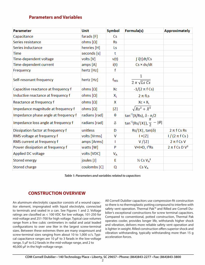
Table 1: Parameters and variables related to capacitors
CONSTRUCTION OVERVIEW
An aluminum electrolytic capacitor consists of a wound capac-itor element, impregnated with liquid electrolyte, connected to terminals and sealed in a can. See Figures 1 and 2. Voltage ratings are classified as < 100 VDC for low voltage, 101-250 for mid-voltage and 251-700 for high voltage. Typical case volumes range from a few cubic centimeters in radial and axial leaded configurations to over one liter in the largest screw-terminal sizes. Between these extremes there are many snapmount and screw-terminal sizes ranging from about 10 to 1,000 cc’s. Typi-cal capacitance ranges are 10 µF to 3 farads in the low-voltage range, 5 µF to 0.2 farads in the mid-voltage range, and 2 to 40,000 µF in the high-voltage range.
All Cornell Dubilier capacitors use compression-fit construction so there is no thermoplastic potting compound to interfere with safety vent operation. Thermal Pak™ and Rilled are Cornell Du-bilier’s exceptional constructions for screw terminal capacitors. Compared to conventional, potted construction, Thermal Pak operates cooler, provides longer life, withstands higher shock and vibration, delivers more reliable safety vent operation and is lighter in weight. Rilled construction offers superior shock and vibration withstanding, typically withstanding more than 15 g acceleration forces.
PRODUCTION PROCESS OVERVIEWFigure 3 shows the production processes. The anode aluminum foil is etched to increase the surface area, and is later anodized during the Forming process, which grows a thin aluminum ox-ide insulating coating to a thickness that provides an electrical insulation up to a potential known as the formation voltage, which is always substantially higher than the capacitor’s rated DC voltage. As the formation process progresses, the thickening dielectric coating reduces the microscopic surface area of the etched foil because the etch tunnels become partially occluded by the oxide. So, for a given etched foil as the formation voltage is increased, the capacitance per macroscopic area drops dra-matically because the area contacting the electrolyte is decreas-ing while the thickness of the dielectric is increasing. Increasing the formation voltage— and thus the dielectric thickness— by 10% would typically result in a capacitance decrease of 13%, re-sulting in a charge storage decrease of 5% and an energy stor-age increase of 5% at the higher formation voltage.
Figure 3: Capacitor manufacturing process
The anode foil etch pattern is optimized for high capacitance or low ESR over a range of formation voltages by choice of foil thickness, alloy, grain structure (cubicity), and etching and forming geometries governed by electrolyte compositions and electrical waveforms. Thus low-voltage anodes have denser tunnel patterns compatible with thin oxide and high-voltage anodes have coarser tunnel patterns compatible with thick ox-ide.
The cathode foil is etched in a different manner than the anode foil, and may be stabilized or passivated but does not usually go through a Forming process.
The anode and cathode foil rolls typically weigh about 100 kg (220 pounds) and are nearly 0.5 meters (20 inches) wide during the foil processing, and are cut into narrower rolls during the Slitting process.
During the Winding process, the anode foil, cathode foil and multiple separator papers are wound together. One or more pairs of aluminum ribbons known as tabs are attached to the foils prior to or during Winding. During the Impregnation pro-
cess, the liquid electrolyte saturates the winding. The top with terminals may be attached to the tabs of the winding before or after impregnation. In an axial-leaded capacitor, the can is at-tached to the negative tab(s).
During the Sealing process, the capacitor element is sealed into an outer package, usually made of aluminum, but sometimes stainless steel or other material. To control pressure build-up, the seal is not usually hermetic but rather a pressure closure made by rolling the can edge into a rubber gasket, a rubber end-plug or into rubber laminated to a phenolic board. Unless specially constructed, too tight a seal may cause excessive pressure build up; while too loose a seal shortens the lifetime by permitting dry-out, which is evaporative loss of electrolyte. After the capac-itor is sealed, it is usually washed to remove electrolyte residue from the outside of the package.
During the Ageing process, a DC voltage greater than the rat-ed voltage but less than the formation voltage is applied to the capacitor. Usually the voltage is applied at the capacitor’s rated temperature, but other temperatures may be used depending upon performance goals. This process re-forms the edges and any damaged spots on the anode foil such as where the tabs were attached. And bare areas or damaged dielectric is repaired with fresh aluminum oxide dielectric. Proper ageing reduces the instance of early application failures (infant mortals). Low initial DC leakage current is a sign of effective ageing. After ageing, the capacitor is tested, sleeved and labeled, packed and finally shipped.
DEVICE PHYSICS
A capacitor is physically created when two conductors are sep-arated by an insulator known as a dielectric. While it may at first appear that an electrolytic capacitor is two conductive alumi-num foils separated by an insulating fluid, this is not the situa-tion because the electrolyte is ionically conductive, and is not an insulating fluid. The actual dielectric is the very thin aluminum oxide (anodic alumina) on the highly etched 3D surface of the anode foil. The etch pattern typically comprises billions of micro-scopic tunnels— 107/cm² is typical for a high-voltage anode— to increase the surface area in contact with the electrolyte. This microscopic to macroscopic areal enhancement factor is often on the order of 50-100 for low-voltage foil and around 20 for high-voltage foil. See Figure 4. The cathode is also chemically or electrochemically roughened, but usually little or no aluminum oxide is grown. The thickness of the anode dielectric coating is proportional to the voltage applied to the foil while in the For-mation bath, about 1.0-1.4 nm per volt.
In an operating aluminum electrolytic capacitor, the alumina has a dry positively charged side integral with the anode alu-minum foil and a wet negatively charged side contacted by the electrolyte, which conducts ionically through the wet separator papers and finally to the cathode foil surface. The electrolyte can be thought of as a “liquid cathode.” The separators (usually cel-lulosic paper) serve as a wick during impregnation as well as a long-term reservoir for the electrolyte. Additionally the sepa-rators prevent physical, electronic contact between the anode and cathode surfaces, which would result in a short-circuit. The
anode foils are usually 80-130 µm thick, the cathode foils 15-50 µm thick and the two paper pads 25-90 µm on each side of the anode.
The wound element comprises an aluminum, high purity anode foil, separator membranes (usually paper) saturated with elec-trolyte and an aluminum cathode foil, usually of lower purity than the anode foil. The foils have aluminum ribbons called tabs welded to them so that terminals can later be attached.
The resulting construction is polar in nature, especially due to the high mobility of protons and hydronium ions readily avail-able in the aqueous electrolyte. The electrolyte is deficient in free electrons, and its main charge carriers are protic hydronium ions H3O+ and negative hydroxyl ions OH-. When the capacitor is forward-biased, the dielectric is dense enough to provide an effective barrier to the flow of hydroxyl ions that are being at-tracted from the electrolyte to the underlying aluminum of the anode foil. However, if continuous or repetitive reverse voltage exceeding about 0.5 to 1.5 volts such as reverse DC voltage or even the negative half cycle of an AC voltage waveform is ap-plied to a polar electrolytic capacitor, protons— which are, af-ter all, much smaller than hydroxyl ions— will not be effectively blocked, and they will readily flow (conduct) through the dielec-
Figure 4: SEM photo of anode foil dielectric structure, after the aluminum which normally fully surrounds the tubes has been dissolved away for clarity. The top photo is an edge view of a 100 µm thick foil from a 400 VDC rated aluminum electrolytic capac-itor. The hollow alumina dielectric tubes are seen to be bundled closely together, with some of the tubes having right-angle bend “elbows.” The bottom photo of the same foil, at 20 times higher magnification, shows a couple of the tube openings as well as a tube that was broken during handling, revealing its hollow cross-section at an elbow. In a finished capacitor, all of the alu-mina tubes are filled with electrolyte.
tric to the negatively biased anode foil. This will cause the water and possibly other ions in the electrolyte to dissociate, attempt-ing to grow aluminum oxide onto the surface of the cathode foil and to liberate hydrogen at the anode foil. Therefore, applica-tion of reverse or AC voltage will rapidly cause heating, hydro-gen gassing, pressure build-up, loss of capacitance and increase in ESR in a polar electrolytic capacitor.
The capacitor element is vacuum-impregnated with electrolyte to saturate the paper separators and penetrate the etch tunnels so that the ionically conducting, liquid electrolyte is in contact with the cathode foil surface as well as the anode foil’s tortu-ous dielectric surface. The other side of the oxide dielectric is in physical, electronic contact to the metal of the anode foil, and thus the dielectric has positive and negative contacts, forming a capacitor. The electrolyte is a complex blend of ingredients with different formulations according to the rated voltage and operating tem-perature range. The principal ingredients are a solvent plus var-ious conductive salts – a solute – to provide ionic conduction. Common solvents are ethylene glycol (EG) and gamma-buty-rolactone (GBL). Common solutes are boric acid, weak organic acids and pH-neutralizing additives such as ammonium salts. Other additives increase stability and longevity by providing corrosion resistance and reducing hydrogen gassing over the lifetime of the capacitor.
Water in the electrolyte plays a big role. It increases conductiv-ity, thereby reducing the capacitor’s electrical resistance, but it reduces the boiling point so it interferes with high temperature performance, and it reduces shelf life. A few percent of water is necessary because the electrolyte maintains the integrity of the aluminum oxide dielectric hydrolytically. When leakage current flows, water is broken into hydrogen and oxygen by hydrolysis, and the oxygen is bonded to the anode foil to heal leakage sites by growing more oxide. The hydrogen liberated at the cathode can be tied up chemically or allowed to form gas and escape through provisions in the packaging. Whenever a polar liquid such as an aqueous electrolyte is in physical contact with a solid conductor— even without an applied voltage— molecular rotations occur in the electrolyte ions near the interface, forming a region of separated, opposite charges. This charge-storage mechanism is called an electric double-layer capacitance, and occurs to a strong degree at the electrolyte-cathode surface and to a lesser degree at the elec-trolyte-anode surface. This makes the cathode a capacitor in se-ries with the anode. Thus in effect an electrolytic capacitor has several capacitances in series, and these vary in different ways with frequency, temperature and voltage.
The expression below gives the capacitance of a prismatic di-electric plate of relative dielectric constant k, surface area A and thickness d. The dielectric of an aluminum electrolytic capacitor is not actually a flat surface, but this simple expression illustrates the principles at work.
Cs = k ε0 A / d (1)
k is a fairly high relative dielectric constant of about 8-10. The constant ε0 is the permittivity of free space, which is 8.854 pF/m. The large effective dielectric area A results from the high de-gree of etching. A very small value of d is achieved by the high continuous operating electric field (typically 50% to 80% of the aforementioned oxide-growth field of 700-1000 V/µm). Togeth-er these properties result in a very high capacitance Cs, enabling a high specific energy and large charge storage device.
ESSENTIAL CHARACTERISTICS AND HOW TO MEASURE THEM
The equivalent circuit below models an aluminum electrolyt-ic capacitor’s normal operation as well as overvoltage and re-verse-voltage behavior.
Figure 5: Equivalent circuit model
Capacitance CsCapacitance Cs is the equivalent AC series capacitance as mea-sured on a capacitance bridge or LCR meter set to “series circuit” measurement mode with no more than 1-volt rms sinusoidal amplitude and without DC bias. The rated capacitance is gener-ally specified near room temperature, 120 Hz sinusoidal wave-form, with 25 °C 120 Hz or 20 °C 100 Hz being the two most com-mon specifications. At low frequency, Cs increases slightly with increasing temperature. Above a certain temperature-depen-dent frequency, the capacitance drops rapidly with increasing frequency. This behavior is most dramatic at very cold tempera-tures and is related to the distributed RC nature of the electro-lyte-filled etch tunnels, and also to the viscosity of the electro-lyte, which directly affects its ionic conductivity. See Figure 6 for a typical plot of Cs versus frequency and temperature.
Figure 6: Typical Cs variation with frequency and temperatureResistance RsResistance Rs is the equivalent AC series resistance as measuredon a capacitance bridge or LCR meter in the same manner as
the capacitance Cs discussed above. Rs usually decreases with increasing temperature, as it is usually dominated by the varia-tion in electrolyte viscosity. However, Rs has other components (metallic and dielectric) which have a positive temperature co-efficient that may dominate in certain capacitors in certain re-gions of the frequency-temperature space. In all cases the ESR decreases monotonically with increasing frequency until the onset of skin effect of the metallic components, typically at 100 kHz or greater. Figure 7 shows typical behavior of Rs versus fre-quency and temperature.
Figure 7: Typical Rs variation with frequency and temperature
Inductance LsInductance Ls is the equivalent series inductance— also known as ESL— which is relatively independent of frequency and temperature. Typical values range from 10 to 30 nH for radial leaded types, 20 to 50 nH for screw-terminal types, and up to 200 nH for axial-leaded types. It increases with terminal spacing and terminal-tab loop area. The inductance of the winding itself is usually very low, often less than 2 nH. At high frequency, the presence of this series inductance causes variations in the measurement of Cs on a bridge or LCR meter.
Figure 8: Typical magnetic flux lines in screw-terminal capacitor with ripple current (the can is not shown). Nearly all of the in-ductance arises from the circuit loop of the terminals and tabs.
Cs, Rs and Ls together with their variations with frequency and temperature impart a device input impedance magnitude seen in Figure 9. At low frequency the capacitive reactance dominates, and at very high frequency the inductive reactance
dominates. In between, the reactances fully or partially offset each other, and Rs constitutes the main component of the im-pedance. At the self-resonant frequency (SRF) the impedance magnitude and ESR curves touch, as seen in the figure.
Capacitor Impedance ZFor detailed information on the device physics impacting the capacitor impedance, and how the impedance varies with temperature, frequency and construction, please refer to our technical paper on impedance models at http://www.cde.com/resources/technical-papers/impedance.pdf and also to our online electrical modeler at http://www.cde.com/spice/ImpedanceAppletIntro.html which displays charts of Cs, Rs and impedance versus frequency and temperature, and will even generate equivalent circuit models.
DC Leakage Resistance RL and Leakage Current (DCL)DC Leakage Resistance RL is the equivalent parallel resistance and accounts for DC leakage current (DCL) in the capacitor. RL decreases (so leakage current increases) with increasing capacitor size and with the applied temperature and voltage. However, once a steady-state voltage and temperature are reached, the leakage current decreases over long periods of time. Leakage current is a function of the historical application of voltage, and a capacitor that has been recently charged will generally exhibit lower leakage current when charged again, than a similar capacitor that hasn’t been charged in many weeks or months. Note that the product of RL and Cs suggests a self-discharge time constant. This time constant is typically on the order of 100 to 1000 seconds, implying that for a 1000 µF capacitor a typical RL value would be 100 kΩ to 1 MΩ. After many hours of steady-state voltage, at moderate core tempera-ture and derated DC voltage, this time constant may increase from minutes to hours.
DCL is measured at 25 °C with the rated voltage applied through a protective resistance of the lesser of 1 kΩ or 10[Ω×F]/Cs in series with the capacitor in the measuring circuit. Five minutes after the application of voltage, the leakage current is not to exceed the maximum value indicated in the specifica-tion. The room-temperature, 5-minute value of RL may be calcu-lated as the applied voltage divided by the measured leakage current. DC leakage current generally decreases over time, but increases with increasing core temperature and with
the applied DC voltage. Figure 10 shows a typical initial leakage current on a screw-terminal capacitor versus core temperature and applied DC voltage.
Figure 10: Typical initial DCL versus voltage and temperature
Zener Diode DzZener diode Dz models overvoltage and reverse voltage behav-ior. Application of overvoltage above the capacitor’s surge volt-age rating causes a very high leakage current, especially when the capacitor is warm or hot, similar to the constant-voltage op-erating mode quite like the reverse conduction of a Zener diode. Application of reverse voltage much beyond 1.5 V causes high leakage current quite like the forward conduction of a diode. Neither of these operating modes can be maintained for long because hydrogen gas is produced by the capacitor, and the pressure build up will cause failure. It is not advisable to attempt to measure the onset of Zener mode or reverse conduction mode, as such tests are generally considered to be destructive.
GENERAL LIMITATIONS, ADDITIONAL CHARACTERISTICS AND TEST METHODS
Operating Temperature RangeThe Operating Temperature Range is the temperature range over which the part will function, when electrified, within the limits given in the specification. It is the range of ambient tem-peratures for which the capacitor has been designed to operate continuously. Largely the formation voltage of the anode foil sets the high-temperature limit. Higher formation voltages per-mit higher operating temperatures but reduce the capacitance. The low-temperature limit is set largely by the cold resistivity of the electrolyte, directly related to the viscosity. The higher cold resistivity often increases the capacitor’s ESR at the lowest rat-ed temperature by a factor of 10 to 100 of the room-tempera-ture ESR. Colder temperatures also reduce the capacitance and change the frequency response characteristics of the capaci-tance, ESR and impedance.
Storage Temperature Range, Short-term and Long-termThe short-term storage temperature range to which the part can be subjected for short periods of time— such as several days— without applied DC voltage, while retaining conformance to specified electrical limits after stabilization at room temperature is generally taken to be -55 °C to the upper category tempera-
ture. The storage atmosphere should be free of halogen gases like chlorine and fluorine that can penetrate the polymeric seals and lead to internal corrosion. Note that subsequent to storage below the minimum operating temperature, the electrolyte may need extra time to recover, to overcome the heat of fusion if it has changed phase from liquid to solid.
Storage without DC bias causes deterioration of the capacitor, especially at high storage temperature. The deterioration mani-fests itself as a reluctance to charge the first time that DC bias is applied after storage. During the first charge after a prolonged storage period— or after a shorter period at elevated tempera-ture— the leakage current is higher than for a recently charged capacitor. Unless otherwise specified on the product datasheet, the long-term storage temperature range is from 5 °C to 40 °C at up to 75% relative humidity (non-condensing), for a period of up to 5 years without the need to “re-form” (re-age) the capacitor. Hotter storage temperatures tend to degrade the capacitor’s ini-tial charge efficiency in a manner that follows the “doubles every 10 °C rule.”
Shelf Life TestShelf life is a measure of how the capacitors will withstand stor-age for long times especially at high temperature, with no ap-plied DC voltage. The rated temperature and duration are gen-erally specified in the datasheet for each of our capacitor series. To verify our shelf life ratings, place the capacitors in an oven set to the shelf-life test temperature –0 +3 °C for the shelf-life test period. Upon completion of the test stabilize the capacitors at 25 °C for 24 h or more. Apply the rated voltage for 30 minutes, then verify the post-test DCL limits. Unless otherwise specified the capacitance, DCL and ESR will meet initial requirements.
Re-ageing, Re-forming, Reconditioning of High DCL CapacitorsIf you have a large group of capacitors which need to be re-formed (re-aged), you may contact us, as we may be able to ap-ply a factory re-age procedure at elevated temperature that will more fully rejuvenate the capacitors, for a nominal processing fee. This is generally done on a best-effort basis, without pro-viding warranty on the capacitors. Otherwise, a simple, room temperature re-age and screening procedure is outlined below.
Recondition high DCL units by setting a DC power supply to the rated DC voltage VR and applying to each capacitor through separate series resistances of value R = 1 kΩ ±10% for 2-4 hours at room temperature. The minimum power rating of the resistor needs to be equal to 2×(VR + 6[V])²/R, or if this is not feasible, the current from the power supply may need to be limited to prevent resistor damage from a delinquent capacitor. Verify that the leakage current of each capacitor— which is equal to the DC voltage across its 1 kΩ series resistor divided by 1 kΩ— is within its specified limit. Capacitors which do not meet their leakage current limit at this stage should be discarded.
Discharge the remaining capacitors for one hour through their series resistors. This can be done by turning off the power supply and shorting its output for one hour. Next set the power supply to a higher voltage, equal to the rated voltage VR plus an addi-tional DC voltage calculated as the rated leakage current limit ILMAX
multiplied by 1 kΩ. Apply this voltage to the capacitors, again through their separate series resistances, for a time equal to 5 minutes plus 5 × Cs × R, e.g. for a 22,000 µF capacitor this would be 5 minutes plus 110 seconds. Verify that at the end of this time, the leakage current of each capacitor— which is equal to the DC voltage across its 1 kΩ series resistor divided by 1 kΩ— is within its specified limit. Capacitors which do not meet their leakage current limit at this stage should be discarded.
Rated DC VoltageThe rated DC voltage is the nominal voltage marked on the ca-pacitor, and it is the maximum peak voltage including ripple voltage that may be applied continuously between the termi-nals, over the rated temperature range. Rated Surge VoltageRated surge voltage is the maximum DC overvoltage to which the capacitor may be subjected at 25 °C for short periods not exceeding approximately 30 s at infrequent intervals of not less than 5 minutes, no more than 1,000 times during the capacitor lifetime.
Surge Voltage TestSubject the capacitors to their rated surge voltage at normal room temperature and through a 1000 Ω ±10% resistor (except for capacitances of 2500 µF and up, use a lower value resistor calculated as 2.5[Ω×F]/Cs ±10% where Cs is the capacitance). Cy-cle the voltage ½ minute on followed by 4½ minutes off during which each capacitor is discharged through the charging resis-tor or equal resistor. Repeat the cycles for 120 h (1,440 total cy-cles). Post-test requirements are for Cs, Rs, D and DCL to meet initial requirements and for there to be no evidence of mechan-ical damage or electrolyte leakage. Electrolyte residue around the top or terminals with no droplets or visible flow is permitted. This is considered a destructive test.
Transient OvervoltageAluminum electrolytic capacitors can generally withstand rapid charging along with occasional overvoltage transient spikes of limited energy. If transients above the capacitor’s rated DC volt-age are anticipated in the application, please contact us to dis-cuss the best capacitor for the application.
Ripple Current Transients and High Inrush CurrentElectrolytic capacitors are able to survive some transient current abuse, typically more than their metallized film counterparts. As a rule of thumb, for brief ripple current excursions such as sev-eral seconds of 2 to 4 times the rated load ripple current, the thermal mass of the capacitor winding will absorb a lot of the extra energy dissipation of such an event. We would encourage you to contact us with your ripple transient requirements. For an example calculation with relevant transient thermal parameters, refer to pages 6-7 of our technical paper at http://www.cde.com/resources/technical-papers/Predict-ing-Operating-Temperature-and-Expected-Lifetime.pdf
For very high inrush or sub-millisecond transient currents such as 10,000 amps peak, please contact us. Although electrolytic capacitors do not suffer from the intrinsically low dv/dt limits of metallized film capacitors, their tabs or terminal connections
may need to be fortified to prevent overheating or even I²t fus-ing. See for example, our analysis of a ringing 16 kA pulse on pages 3-5 of our technical paper at http://www.cde.com/resources/technical-papers/TransientMo-delingOfLargeScrew-TerminalAluminumElectrolyticCapacitors.pdf
We would encourage you to contact us when you expect current transients involving over 1,000 amps peak.
Charge-Discharge Duty and High Peak-to-Peak VoltageFrequent charge and discharge of aluminum electrolytic capac-itors— whether rapid or slow— not designed for such service can damage the capacitors by overheating and overpressure or breakdown with consequent failure by open or short circuit. For charge-discharge applications use capacitors designed for that use, such as our photoflash and strobe capacitors, Type PF, 7P and ST, or contact us for a special design for your requirements.
High continuous ripple voltage can eventually have the same effect as charge-discharge duty, only to a lesser degree. High core temperature accelerates the degradation. As a general rule, if the peak-to-peak capacitor voltage divided by the capacitor’s rated voltage VR exceeds the greater of 10% or
0.01352 × (VR / 1[V])1/2 (2)
on a continuous or frequent basis, then please contact us to re-view the capacitor design for best performance with your volt-age waveform. This is a ratio of 10% up to 55 VDC rating, 14% at 100 VDC, 21% at 250 VDC and 29% at 450 VDC ratings.
Insulation and Grounding, Case and Dummy Pins, SleevingIn aluminum electrolytic capacitors, the metal cases connect ionically and possibly electronically to the negative terminals by contact with electrolyte. In order to avoid galvanic issues, if objects contacting the cases are to be at a potential other than the negative terminal’s potential, use capacitors with insulating sleeves. The key concept is that current flow should be prevent-ed through the can to either terminal. In general the can should be allowed to float, electrically. The same rule applies for any non-electrified dummy pins; it is best not to ground them but rather to let them float.
The plastic insulation can withstand 3000 VDC or 2500 VAC RMS at room temperature, 50 or 60 Hz for 1 minute applied between the case and a ¼ inch (6 mm) wide metal foil placed around the sleeve without breakdown or punch-through of the insu-lation. For testing the stud-mount insulation, apply the voltage between the mounting plate and the case, and mount the ca-pacitor with an approved plastic nut and appropriate clearance hole. For high dielectric withstanding voltage, we offer dou-ble-sleeved insulation systems. Contact us for details. Insulation resistance is no less than 100 MΩ after 2 minutes electrification with 100 VDC applied between the foil and the capacitor case.
The standard PVC sleeves that we supply are primarily for la-beling purposes. Although they will initially pass the aforemen-tioned breakdown tests, they do degrade (oxidize) over time,
especially above 65 ºC. These sleeves are not suitable for long-term, high-voltage insulation at high temperature, especially in critical applications, and we recommend that you provide an ad-ditional level of more-durable insulation if permanent insulation at high voltage is required.
Elevation (Altitude) and External PressureUnless otherwise specified on our product datasheets, our alu-minum electrolytic capacitors can operate to 80,000 feet and pressures as low as 3 kPa. However, above 10,000 feet (3 km, 70 kPa) altitude the ripple current ratings need to be reviewed due to the lowering of the convection coefficient caused by the low-er air density and mass flow rate. Above 60,000 feet (17 km, 8 kPa) the creepage and clearance distances for capacitors with DC voltage above 200 VDC should be reviewed for impact by Paschen’s Law. For assistance with these potential issues at high altitude, please contact us.
Our electrolytic capacitors can withstand brief or continuous exposure to 1.5 atmospheres absolute pressure (150 kPa or 22 psia). The issue with higher pressure than this is the tendency to drive airborne contaminants or fumes through the capacitor seals and into the capacitor. For assistance with applications that require higher external pressure, please contact us. Mechanical Vibration and Shock Most of our aluminum electrolytic capacitors can withstand test conditions imparting peak vibration accelerations of 10 g’s. More specific limits are shown in the specifications for each capacitor series. Frequencies are usually in the range of 10 to 2,000 Hertz. We offer some series that are specially constructed to withstand testing up to 80 g’s. We can meet many of the standard swept-sine or random vibration profiles of MIL-STD-202. Contact us if you have a particular vibration test profile our capacitor needs to meet. Continuous vibration exposure in the field needs to be well below the peak test levels.
Mechanical shock testing involves a gravimetric drop test with an acceleration waveform such as sawtooth or half-sine, which imparts an acceleration pulse with a shape, width and peak val-ue. The acceleration profile is controlled by the pad or target which the capacitor strikes at the bottom of the drop zone. We can meet many of the standard drop test requirements of MIL-STD-202. Contact us to discuss your particular shock require-ments.
Thermal Cycle, Immersion and Thermal ShockMost of our aluminum electrolytic capacitors can withstand test conditions involving application of several thermal shocks from room temperature to the upper and lower category tempera-tures in a rapid manner. These are generally tested per the meth-ods specified in MIL-STD-202G, such as Method 107G. If you have thermal shock, thermal cycle or immersion requirements, please contact our Engineering department so that we can dis-cuss your needs and our capabilities.
Polarity – Reverse VoltageCheck the polarity of each capacitor during and after assem-bly. Polarity is marked on the capacitor. While the capacitors may withstand continuous application of 1.5 V reverse volt-
age, exceeding that can damage the capacitor by overheat-ing, overpressure, and dielectric breakdown. This can result in open-circuit or short-circuit failures and rupture of the capac-itor’s pressure-relief vent. Non-polar and semi-polar devices are available that can withstand continuous or frequent reverse voltage application. Please contact us for such capacitors if your application requires such capability.
Anti-series Connection, Non-polar, AC and Motor-start CapacitorsIf two, same-value, aluminum electrolytic capacitors are con-nected in anti-series configuration with the positive terminals or, more usually, the negative terminals connected together, the resulting single capacitor is a non-polar capacitor with half the capacitance. When voltage is applied to this anti-series combi-nation, the correct-polarity capacitor gets nearly the full voltage.
CDE also offers non-polar capacitors in a single can, using two anode foils and no cathode foil. Most motor-start capacitors are also constructed this way. These are available for momentary-du-ty AC applications like motor starting and voltage-reversing ap-plications, but the high dissipation factor of aluminum electro-lytic capacitors— often exceeding 2% – causes excess heating and short life in most continuous AC applications. The reverse voltage capability is not constrained to be the same as the for-ward voltage, as we can also create special designs that have, for example +400 VDC and -25 VDC capability. This is done by using two anode foils with different formation voltages.
If your application requires AC voltage or reverse voltage capa-bility, please contact CDE, as we can often create special designs to handle such requirements, or we can recommend an alterna-tive technology such as metallized film.
Self-Resonant Frequency (fRES or SRF)The self-resonant frequency is the frequency whose formula is shown in Table 1 near the beginning of this document. At this frequency the capacitive reactance equals the additive inverse of the inductive reactance, thereby causing the remaining im-pedance to be purely resistive and thus equal to the ESR at that frequency. At frequencies greater than the SRF, the device is in-ductive. In aluminum electrolytic capacitors the self- resonant frequency typically occurs at less than 100 kHz. It occurs at a fre-quency higher than expected based on 120 Hz capacitance be-cause the capacitance Cs decreases with increasing frequency. fRES can decrease with increasing temperature because Cs typi-cally increases with increasing temperature.
Dielectric Absorption (DA)Dielectric absorption may be observed as a voltage rebound on a recently charged capacitor after the terminals have been shorted for a brief period followed by removal of the short cir-cuit. This effect is more pronounced after DC voltage has been applied for an extended period of time, especially at elevated temperature. Due to the relatively high value of DA, electrolytic capacitors may have issues in timing circuits, voltage-controlled oscillators (VCO’s), analog memory, analog integrators, A/D con-verters (ADC’s), etc.
For aluminum electrolytic capacitors, dielectric absorption will allow up to 10% recovery of a previously applied voltage. Thus with high-voltage aluminum electrolytic capacitors rebound voltages of 40 to 50 V are possible. While such voltages are not usually a shock hazard, they can certainly cause sparking and even arc damage during installation. CDE fully discharges its ca-pacitors prior to shipment, and uses special packaging to pre-vent voltage rebound during shipment and during storage in the original packaging. If the capacitors are removed from their original packaging many hours before assembly, the customer should provide additional means of assuring the capacitors are discharged again just prior to assembly.
There are many test methods for measuring dielectric absorp-tion, and they do not all give the same result, due to variations in the charge vs discharge times. One such test method is JIS-C-5012, in which a DC voltage is applied for 60±1 minutes, followed by rapidly discharging and holding the terminals in a short-circuit condition for 10±1 seconds, followed by open cir-cuit. Monitor the voltage that subsequently builds at the termi-nals in a manner that doesn’t tend to load the capacitor down, such as with an electrometer, vacuum tube voltmeter or other monitoring method with high input impedance. The capacitor terminal voltage will build over several minutes, either reaching a peak value or approaching an asymptotic value, depending upon the relative leakage current and other factors. That peak or asymptotic voltage divided by the original charge voltage will give a unitless ratio that is equal to the measured DA, which can be expressed as a fraction or as a percentage.
CAPACITOR BANK CONFIGURATIONS
General ConsiderationsCapacitor bus structures should be designed to interconnect the capacitors in a reliable and consistent manner. For screw termi-nal capacitors, make provisions to provide clearance around the vent plug areas, such as through-holes above each vent plug. Provisions such as ¼” (6 mm) diameter through-holes allows the vent plug to swell without being obstructed; in the case of a vent rupture, it gives the electrolyte steam a clear channel. A clearance hole above each vent plug can also provide windows that allow for inspection to determine if the vent plug is visibly swelling, indicating abnormal pressure build-up or end of life-time. An array of such windows can be useful just after bank as-sembly, prior to first charge-up, to assure that all capacitors have been installed with the correct polarity.
Capacitor bus structures should connect to the capacitor termi-nals in a manner that does not cause a large local heat rise at the capacitor terminals, as it is much better to be drawing heat out of the capacitor than adding to the capacitor’s heat load. This means using the appropriate bus conductor sizing and proper terminal torque. At the same time, the bus plates need to avoid being so heavy that mechanical stress is put on the capacitor terminal surfaces, such as forcing coplanarity of the capacitor terminal surfaces rather than conforming to them.
In the case where more than ten capacitors (large screw-termi-nal or smaller snap-in) are connected in parallel on a bus, it is advisable to discuss the application with us, as sometimes slight
tweaking in the capacitor design will give higher reliability at lit-tle or no additional cost.
When laying out a grid of capacitors, consider the effects of thermal resistance as well as high frequency impedance. A 3×4 physical grid will have two capacitors in the center surrounded by other capacitors. The center capacitors will tend to run much hotter if the ripple current is significant, unless special cooling techniques are implemented. These thermal effects are demon-strated in Figure 11 below. Thus, thermally on an n×m grid, it is best if n or m is no greater than 2. On the other hand, a long and narrow capacitor bank bus structure can present a tougher chal-lenge to achieve equal sharing of high-frequency ripple current.
Figure 11: Mutual heating among capacitors: Centermost capac-itors run much hotter
PARALLEL CONNECTION
Capacitors may be connected in parallel for increased capaci-tance and ripple-current capability.
Bus StructureWhen connecting capacitors in parallel, design the connecting bus with these features in mind. For minimum series inductance use a laminated-bus or strip-line structure. For example, have one plane of the circuit board as the plus connection and an-other plane as the minus connection to all capacitors. At low frequency the variations in capacitance among the capacitors will dominate the variations in ripple current distribution, while at high frequency the ripple current shifts to divide according to the bus admittance and reciprocal-ESR value. The latter tends to vary significantly with core temperature. At high frequency, the ESL of the capacitor also needs to be considered, and the pathimpedance from the bus feed port(s) to each capacitor should be nearly equal to assure equal current sharing.
Fusing and Soft StartFusing capacitors is usually not done in high-power capacitor banks because the fuses add too much resistance and induc-tance. However, it is worthwhile to contemplate any scheme or feature that can be added to a bus structure to limit the collat-eral damage of the rare situation of a short-circuited capacitor. Although aluminum electrolytic capacitors do not have the dv/dt limits of their metallized-film counterparts, their slight risk of
failure during start-up after a long period of unenergized stor-age is reduced if a slow-start circuit is implemented.
SERIES CONNECTION
Capacitors may be connected in series for increased voltage withstanding.
Voltage SharingDuring charging the voltage on each capacitor connected in se-ries is proportional to the inverse of the actual capacitance, but upon reaching the applied voltage, the steady-state DC voltage that each capacitor approaches no longer depends upon its ca-pacitance at all, instead shifting to follow the inverse of the ca-pacitor’s leakage current.
In a series-connected string of capacitors there is only one leak-age current, and the capacitors with a propensity for higher leak-age current will thereby get less voltage. Since leakage current increases with the applied voltage, less voltage results in higher leakage resistance RL, and voltage mismatches are somewhat mitigated by this mechanism. Over time the leakage current of each capacitor and thus of series connection generally diminish-es. But the capacitor voltage division is dependent on the ratios of the various leakage current vs voltage profiles— not to the average magnitude— and these ratios may actually increase even as their magnitudes decrease, resulting in the capacitors becoming less and less well self-balanced. It is possible that a capacitor may even drift to a voltage above its rated voltage, which may cause the electrolyte to spark and lead to a short-cir-cuit of a capacitor.
Since the voltage distribution of series-connected electrolytic capacitors cannot be depended upon to be uniform, we recom-mend that the voltage ratings be derated and that a balancing scheme be implemented, such as balancing resistors. Assist volt-age sharing stability by using capacitors from the same manu-facturing lot and mounting them to operate at the same core temperature. This practice typically reduces the spread in the capacitance, ESR, and leakage current profile.
Balancing ResistorsThe leakage current of CDE aluminum electrolytic capacitors at rated temperature can be estimated as IL = 1.5[mHz] × Cs × VA where VA is the applied DC voltage, at or below its rated DC voltage. The maximum difference in leakage currents among n capacitors in series, each of capacitance Cs, at rated tempera-ture can be estimated using the same formula by substituting VA = Vb/n where Vb is the total bus voltage. Using this estimate enables the selection of a value of balancing resistance to be connected in parallel with each capacitor as follows:
670[Ω∙F]×(n∙VM-Vb)
(n-1) Cs VM (3)
where VM is the maximum voltage you’ll permit on any capaci-tor. The above typically establishes equalization response time constants of about n/(n-1) minutes after the bus voltage is ap-plied.
Be sure the resistors are rated for power of at least 2VM²/R, and lay them out in a manner that doesn’t heat the capacitors. The resistors should be purchased as or matched within ±1% toler-ance.
PARALLEL / SERIES BANK
Capacitors connected as shown below with a common connec-tion between n multiple series combinations have these consid-erations.
Figure 12: Parallel-series array with common center connection
Advantages: Statistically as the number of capacitors in parallel m increases the capacitance at the top tends to equal the ca-pacitance at the bottom. This improves voltage balance during transients. For the same reason the leakage current at the top tends to equal the leakage current at the bottom, so voltage balance improves during steady-state conditions. Finally, only n balancing resistors need be considered. To calculate the R value, use the same equation but increase the value of Cs to be be-tween √m×Cs (aggressive, assuming RSS statistical distribution of leakage currents) to m×Cs (conservative, assuming no statisti-cal benefit of parallel connection on leakage current).
Disadvantage: If one capacitor fails short, the other half of the bank gets the entire bus voltage, so other capacitors will fail too unless the shorted capacitor blows open. Thus one capacitor failure can cause failure of the entire bank.
SERIES / PARALLEL BANKCapacitors connected as shown below with multiple series com-binations in parallel have these considerations.
Figure 13: Series - parallel array, no common center connection
Advantages: If one capacitor fails short then the capacitors in series with it also fail, but other capacitors in the bank are unaf-fected. The independent, series pairs may permit fusing.
Disadvantages: With balancing resistors the construction is more complex; many resistors need to be fitted, and the addi-tional resistors cost more.
Reliability ModelAluminum electrolytic capacitors are quite reliable largely be-cause of their effective, self-healing mechanism. While wearout is the most common failure mode, most such failures are grad-ual conversions to open circuits as the units become more and more resistive. The chance of a capacitor failing before the onset of wearout is not zero. This chance per unit time is the failure rate, λ, which is initially high, but is greatly reduced during the ageing and screening processes we perform on each capacitor before shipment. This is the infant mortality rate seen as the left side of the “bathtub curve” shown in Figure 14. During the useful lifetime of the capacitor, the failure rate is low and fairly constant, which establishes the value for λ. Our online lifetime calculators available at http://www.cde.com/technical-support/life-temperature-calculators report our estimated value of λ for many of our more popular capacitor series. The equation used to calculate λ is discussed below.
We have a model for the rate of random failures in terms of the number of capacitors in the capacitor bank and the ratings of the capacitors versus how hot they are being run and what per-centage of their rated DC voltage is being applied. The details of this model are given in our technical paper on electrolytic capacitor reliability at http://www.cde.com/resources/techni-cal-papers/reliability.pdf
The model for the base failure rate (bottom of the bathtub curve) from the above resource is summarized below:
The above expression has units of inverse-time, i.e. fractional failures per unit time. From this you can readily express as ppm/kh (“FIT” rate) or % per year, etc. In the equation, N is the number of capacitors in the array, VA is the applied DC voltage, VR is the rated DC voltage, Cs is the capacitance of each capacitor, Tc is the core temperature, Tm is the maximum rated core tempera-ture and Lb is the base lifetime. Tm and Lb are tabulated for each capacitor type in Table 2.
Figure 14: The “Bathtub Curve”
Ripple Current, Load Life Tests, Ripple MultipliersRipple current is the AC current flowing through the capacitor. It’s called ripple current because the associated AC voltage rides on the capacitor’s DC bias voltage as a ripple rides on the surface of water. The ripple current heats the capacitor, and the maxi-
mum permitted ripple current is set by how much heat rise can be permitted while still meeting the capacitor’s load life speci-fication. Too much temperature rise will cause the capacitor to exceed its maximum permitted core temperature and fail; even operation close to the maximum permitted core temperature dramatically shortens expected life.
The Load Life Test is a life test at elevated temperature with DC voltage as well as ripple current applied. The load life specifica-tions for aluminum electrolytic capacitors operating near their maximum permitted core temperature are typically 1000 to 20,000 hours. That’s a duration of six weeks to 2.28 years, insuffi-cient for most applications. Nearly all applications have derated conditions of temperature, voltage and ripple current versus the load life test conditions.
Ripple current ratings usually assume that the capacitor is con-vection-cooled and that the entire can is in contact with air. A total heat transfer coefficient of roughly 10 [W/m²K] predicts the temperature rise from ambient air to the case, and the core tem-perature is assumed to be the same as the case temperature. The dissipated power is the ripple current squared times the ESR. The heat rise is the dissipated power multiplied by the thermal resistance. Even though the capacitor case is not an isothermal surface, often the thermal resistance is separated into two com-ponents, core-to-case and case-to-air. The former is dominated by conduction and the latter by radiation and convection. There is a common misconception that heat transfer from radiation is negligible around room temperature, as compared to convec-tion. In reality, when there is no forced convection— only natu-ral convection— the radiative heat transfer component can be of the same magnitude as that of convection. For a discussion of the details of thermal modeling of aluminum electrolytic ca-pacitors, see our two technical papers on this subject at http://www.cde.com/resources/technical-papers/thermalmodel.pdf and http://www.cde.com/resources/technical-papers/Predict-ing-Operating-Temperature-and-Expected-Lifetime.pdf
For DC Link and other filter capacitor applications, usually there is more than one frequency present in the ripple current spec-trum. The ESR varies nonlinearly with both frequency and tem-perature, and the 120 Hz room temperature ESR limit is usually not helpful in estimating the core temperature. Therefore we recommend that you use our online tools to estimate the ESR’s, thermal resistances, core temperatures and lifetimes. You will find these tools at http://www.cde.com/technical-support/life-temperature-calculators The “double applets” are best for desktop computer screen and facilitate what-if analysis by trans-ferring information back and forth between two instances of the modeler.
Our online calculators allow up to two ripple frequencies to be inputted. Note that when two frequencies are entered, the total ripple current is the RSS (root sum square) of the two fre-quencies, not the algebraic sum. When you have many ripple harmonics present, the best way to model as two frequencies is to partition the components and assign to a low-frequency and a high-frequency. Because the ESR decreases monotonically with increasing frequency, any error with this spectral allocation will be conservative (slightly overestimating core temperature
heat rise and underestimating the expected lifetime) if you lump the low-frequency components to the lowest frequency in that low-frequency range, and all of the high-frequency components to the lowest frequency in that high-frequency range. You may perform a sensitivity analysis by noting the effect of increasing the two frequencies.
For qualification of our capacitors, we can provide capacitors with thermocouples embedded in the core so that you may take measurements and compare to the estimates from our online modelers. Our online modelers allow you to refine the modeled ESR’s, and you may thereby tweak these values or the applied ripple currents to agree with the heat rises measured in the ther-mocoupled capacitors, in order to provide more accurate heat-rise inputs to the lifetime modeler.
Avoid using total effective ripple multipliers (i.e. including both frequency and ambient temperature multipliers) greater than about 2 for ripple current ratings at and below 85 °C ambient, and about 3 for ripple current ratings at and above 105 °C am-bient, since high ripple current can cause shorter operating life-time than expected due to ESR increase during the capacitor lifetime, which accelerates wearout.
Ripple Multiplier TablesIn the datasheets for our various product series, we usually publish ripple multiplier tables for frequencies other than 120 Hz and for ambient temperatures other than the rated life test temperature. As these tables typically cover a range of different capacitors, they should be used as a rough guide as to the equiv-alent ripple current to cause the lifetime to be about the same as the rated load life test lifetime. For example, if the load life test rating is 5,000 hours at 85 °C with 15 amps of 120 Hz ripple current and your application is at 45 °C ambient with a frequen-cy of 20 kHz, and our ripple multiplier tables indicate a ripple multiplier of 2.0 for an ambient temperature of 45 °C and a ripple multiplier of 1.2 for 20 kHz, then the overall effective ripple mul-tiplier is the product of these two multipliers, which is 2.0 × 1.2 = 2.4. However, it is important to not “try to have your cake and eat it, too” by taking license to actually apply 2.4 × 15 = 36 amps of ripple current in your application, because the expected lifetime would only be the rated load life test duration of 5,000 hours. Most applications target 100+ kh lifetime and would need to limit the ripple current to no more than the load life ripple rating even at the lower application temperature. For further informa-tion on how ripple current multipliers work, see our IEEE paper, available at http://www.cde.com/resources/technical-papers/multipliers.pdf
Operating Lifetime ModelOnset of wear-out is determined mainly by the capacitor’s aver-age operating temperature. Operating voltage has some effect. For capacitors operating at moderate temperatures the oper-ating life doubles for each 10 °C that operating temperature is reduced. Our online lifetime calculators available at http://www.cde.com/technical-support/life-temperature-calculators report our best estimates of the useful lifetime for many of our more popular capacitor series. The expected operating lifetime is ap-proximately
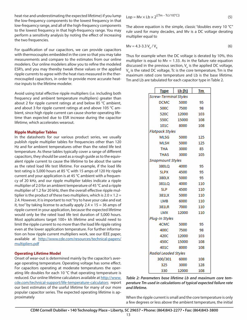
Lop = Mv × Lb × 2((Tm – Tc)/10[°C]) (5) The above equation is the simple, classic “doubles every 10 °C” rule used for many decades, and Mv is a DC voltage derating multiplier equal to
Mv = 4.3-3.3 VA / VR (6)
Thus for example when the DC voltage is derated by 10%, this multiplier is equal to Mv = 1.33. As in the failure rate equation discussed in the previous section, VA is the applied DC voltage, VR is the rated DC voltage, Tc is the core temperature, Tm is the maximum rated core temperature and Lb is the base lifetime. Tm and Lb are tabulated for each capacitor type in Table 2.
Table 2: Parameters base lifetime Lb and maximum core tem-perature Tm used in calculations of typical expected failure rate and lifetime.
When the ripple current is small and the core temperature is only a few degrees or less above the ambient temperature, the initial
value of Tc may be used in the lifetime equation, with the tacit assumption that Tc is constant during the capacitor’s useful life-time. In actuality Rs increases during the capacitor’s lifetime— generally assumed to double from the initial value by the end of the useful lifetime— and the heat rise would rise in proportion to the increasing value of Rs. To account for the increase in core temperature Tc we recommend that for an initial core rise ΔTo above ambient, when the lifetime equation is used, instead of the usual initial core temperature value of Tc = TA + ΔTo that the following value for Tc be used
Tc = TA + 1.5 × ΔTo (7)
Cornell Dubilier was the first in the industry to develop and use the lifetime estimate refinement of equation (7), implemented in our online calculators since the mid-1990’s. Effectively, the ambient temperature is penalized as halving the lifetime every 10 °C while the ripple current heat rise is penalized as halving the lifetime every 10 °C ÷ 1.5 = 6.67 °C.
Though the equations for lifetime are simple, it can be a chal-lenge to estimate the initial heat rise ΔTo because to do so one needs to know both the Rs value at the core temperature and frequency (which is actually often multiple frequencies) as well as the total thermal resistance qT from the core to the ambient.
ΔTo = P qT = I² Rs qT (8)
We recommend that you use our online thermal/lifetime calcu-lators to estimate the dissipated power, core temperature and lifetime. If possible, cross-check those temperature rise esti-mates using sample capacitors with embedded thermocouples. It may be feasible to measure the dissipated power using a wide-band power meter, but you need to account for the resistance of the leads. Then you can use the appropriate Thermal Resistance Chart in this application guide along with equation (8) to esti-mate temperature rise.
Lifetime calculations for varying ambient temperature or varying ripple currentWhen the applications stressors such as applied DC voltage, am-bient temperature or ripple current vary over time, the lifetime equations we have presented can still be used, but they need to be averaged nonlinearly. This is discussed on pages 15-18 of our presentation athttp://www.cde.com/resources/technical-papers/TransientMo-delingOfLargeScrew-TerminalAluminumElectrolyticCapacitors.pdf
Load Life TestPlace the capacitors in a circulating air oven set to the upper temperature limit ±2 °C. Apply a DC voltage and an AC ripple voltage. Adjust the AC voltage to cause current equal to the rat-ed ripple current to flow and adjust the DC voltage such that the peak voltage equals the capacitors’ rated voltage. Apply the voltage for the rated load-life period –0+6 h. Upon completion allow the capacitors to stabilize at 25 °C for 24 h or more. The ca-pacitors will meet the specified post-test limits for capacitance, ESR and DCL.
EIA Ripple Life Test, EIA IS-749Conduct the wear-out lifetime test per EIA Interim Standard 749. The highlights of that test are as follows:Apply ripple current at 120 Hz or adjust to maintain the same power dissipation if performed at another frequency. Set DC bias voltage equal to rated voltage minus peak applied AC voltage. Set ambient temperature to 85 ± 2 °C with airflow less than 0.5 m/s. Periodic test interval ≤ 1000 h. Sample size is 10 or more. Mount capacitors horizontally and spaced 25 mm or more. Choose any temperature ≤ 85 °C for measurements, and make all measurements at that temperature. End of Lifetime is the time when 10% or more of the sample have: capacitance < 80% initial value or ESR > 200% of initial limit or DCL > initial value or there is evidence of mechanical damage or leakage of electrolyte.
Up to 10% of sample may fail short or open and not be counted.
Estimating Lifetime for Capacitors without an Online CalculatorWe offer online calculators for many of our capacitor series such as our screw-terminal, snapmount and flatpack capacitors. For our capacitor series without a calculator, you will find on its datasheet a “load life rating” with an ambient test temperature and duration at the rated ripple current, which is tabulated for each capacitor within that series. To estimate the minimum life-time, you may select a capacitor whose tabulated ripple current is at least equal to your application’s ripple current, and apply the “doubles every 10 °C” rule between the load life test ambi-ent temperature and your application’s ambient temperature. If your DC voltage is derated, then you may multiply the lifetime by the voltage multiplier Mv given in equation (6). This will be an estimate of the minimum expected lifetime. Typical lifetime will be greater, up to twice this estimate.
COOLING AND THERMAL RESISTANCE
Cooling StrategiesBecause of their ThermalPakTM construction, Cornell Dubilier screw-terminal capacitor windings conduct heat from the core of the winding to the can bottom much more effectively than to the sides of the can. You can take advantage of this heat path by mounting the capacitors directly to a metal chassis. In many case sizes this can double the permitted ripple current for the same temperature rise.
Mounting can be done by using capacitors with mounting studs and screwing the capacitors directly to the plate or it can be achieved by pressing the capacitors against a plate using the interconnecting bus structure. Cornell Dubilier offers sil-pad inserts at the bottom of the capacitors for this application. The sil-pads create smooth bottoms by eliminating the steps at the sleeve rollovers. The thermal resistance between the can and the underlying plate for capacitors merely sitting on the plate is about 2.5 °C/W. This decreases to less than 1 °C/W if the capaci-tors are pulled tightly into place. Calculators are available on the Cornell Dubilier website which permits you to explore cooling options and directly see the effect on operating life.
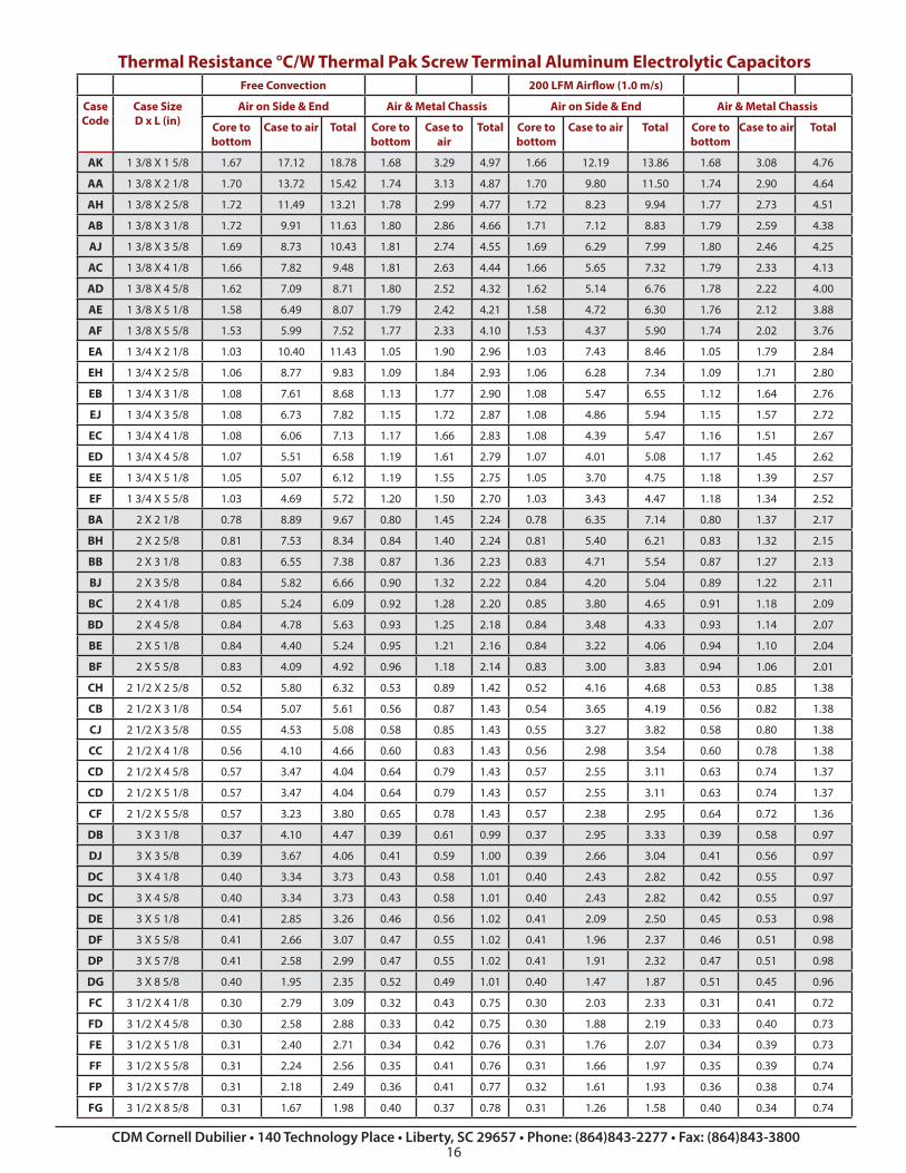
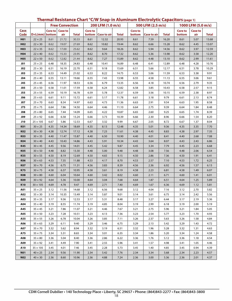
Thermal ResistanceIn large-can capacitors there can be significant temperature rise from the case to the core, the hottest spot at the center of the ca-pacitor. For Cornell Dubilier Thermal Pak screw-terminal capac-itors use the thermal resistance data tables in this application guide to determine temperature rise from power dissipated. As an illustration, consider 20 amps of ripple current at 120 Hz in a 3 x 5 5/8 case with a maximum ESR of 20 mΩ. The hot, typical ESR would be about half that or 10 mΩ, and the power dissipated would be I²Rs, 20²x0.01 or 4 W. For the DF case code the table shows that the thermal resistance from core to bottom of the can is about 0.41 °C/W. That varies a little depending on how the capacitor is cooled, but 0.41 °C/W predicts a temperature rise of 1.6 °C between the core and the can for 4 watts of power dissi-pation. The free-convection cooling column shows a total ther-mal resistance of 3.07 °C/W for air on all sides and 1.02 °C/W for the capacitor pressed against a large metal plate or chassis. The 3.07°C/W predicts a temperature rise of 12.3 °C, and 1.02 °C/W predicts 4.1 °C.
PROCESS CONSIDERATIONS
SOLDERING
Wave and reflow soldering tipsDon’t exceed the maximum storage temperature while preheat-ing the capacitors. If this cannot be avoided, contact the suppli-er first. Strictly adhere to soldering conditions for temperature, duration and minimum distance of solder from body. Don’t con-tact insulating sleeve or other plastic parts with a soldering iron or molten solder. Reflow solder only SMT types, and then only one reflow cycle. Contact the supplier if more than one reflow is necessary. Care after SolderingDo not exert any mechanical force like bending, straightening, twisting or tilting of capacitors after soldering into a printed cir-cuit board.
Handling Circuit Board AssembliesDuring transport and handling of assembled devices do not misuse capacitors as a handle. Ensure that capacitors are pro-tected from physical damage during mounting of printed circuit boards into assemblies or during stacking.
Halogenated-Solvent CleaningHalogenated hydrocarbon solvents (CFC) are ozone-depleting chemicals harmful to the environment. Such solvents can pene-trate the capacitors’ seals and cause corrosion and failure when voltage is applied, and so use them to clean aluminum electro-lytic capacitors only to the limited conditions given by the com-ponent supplier and then only as a last resort. Solvent-proof miniature capacitors and capacitors with epoxy end-seals are available for limited use with halogenated solvents.
Aqueous CleaningWater with a mild detergent may be used to clean aluminum electrolytic capacitors. However, immediately dry the capacitors
in hot air at about 85 °C for 5 or more minutes but not hotter than the capacitors’ maximum storage temperature. Water can become trapped beneath the sleeve which may not be dispelled by evaporation at room temperature. Water can be trapped un-der the sleeve and cause hydration and discoloration of the alu-minum cases; although this does not affect capacitor operation.
Alcohol and solvent cleaning to remove solder flux residueAvoid the use of halogenated cleaning solutions for cleaning aluminum electrolytic capacitors. Our standard sleeve material is PVC. Most cleaning solvents may cause slow hydrolytic deg-radation of the alternative, higher-temperature polyester (PET) sleeves, so check carefully before cleaning capacitors with PET sleeving. For standard aluminum electrolytic capacitors with PVC sleeves, there are halogen-free solvents available such as ethanol, propanol, isopropanol, isobutanol, propyleneglycol ether, diethyleneglycol ether but these might not be as effective in removing flux residue as the newer, fatty alcohol, alkaline sa-ponification or surfactant cleaning solvents. Certain of the latter have been reported to be sufficiently low in halide content, such as:
Pine Alpha ST-100STechno Care FRW 14 through 17Sanelek B-12Clean-Through 750H, 750L, 710MAqua Cleaner 210SEP
Cleaning PrecautionsClean at no higher than 60 °C for no longer than 10 minutes. The capacitor’s insulating sleeve may re-shrink or crack if rapidly heated to above 100 °C just after cleaning, so dry after cleaning at no higher than 85 °C. If the solder flux contains chlorine as many active flux types do, frequently regenerate or replace the cleaning solvent to avoid damaging the capacitors. Cleaning solvents may swell the insulating sleeves and affect the legibility of marking if applied too long or with too high mechanical forc-es or temperatures.
Potting and GluingBe certain that varnishing, coating, lacquering, embedding and gluing near the capacitors’ seals are halogen free. And be sure all constituent parts including base material, thinners, binders, re-acting agents, propellants and additives are halogen free. If the printed circuit board has been cleaned with halogenated sol-vent, be sure it’s fully dry before installation of capacitors. When gluing, don’t apply glue to the full capacitor circumference, and don’t cover the capacitors’ pressure-relief vent with potting or glue. Fumigation WarningInternational shipments of electronic equipment are often in wooden crates, and these crates may be fumigated with methyl bromide gas during shipment to control insect infestation. Also, some factories such as flourmills are routinely fumigated with this gas. Methyl bromide can penetrate cardboard boxes, vinyl bags and other packaging materials used to protect the ship-ment. Methyl bromide can also penetrate the seals of aluminum electrolytic capacitors; cause corrosion and cause open-circuit
capacitor failure after the equipment is put into service.To protect aluminum electrolytic capacitors against such fail-ures, use capacitors proven to be able to withstand fumigation or individually sealed to prevent penetration of the methyl bro-mide gas. Screw terminal capacitors with rubber vent plugs are the most susceptible type.
MOUNTINGMounting PositionAluminum electrolytic capacitors have longer operating lives at lower ambient temperatures; so, put the capacitors at the coolest place on the board. Ensure that aluminum electrolytic capacitors are away from hot components like power resistors, power transistors or diodes and transformers. Adequately space components apart for cooling air to circulate. This is especially important when high ripple current or charge/discharge loads are applied.
For two-leaded radials and snapmount capacitors mounted di-rectly to the circuit board, consider vibration requirements. A lone, unsupported two-leaded capacitor may tend to rock and break at the leads more than its counterparts with 3 or more leads. Banks of two-terminal, radial-leaded capacitors in close proximity may benefit from adhesive applied to them, creating a more rigid structure that is more resistant to vibration and me-chanical shock. However, the ripple current capability of such a bundle will be less than the sum of the individual ripple currents of individual units because the effective surface area is reduced.
Some customers have reported issues when using conformal coating on radial-leaded capacitors that have been mounted tightly against the board. This may tend to trap flux residue or, if washed but not thoroughly dried, water vapor. Also, if such capacitors are run with high core temperature, the small amount of gas that escapes around the seal of the capacitor during its operation may tend to be trapped in the cavity. If this is an issue in your application, we do offer snap-in and other style capaci-tors with three or more leads with built-in standoffs that prevent such gas entrapment. Another alternative might be to design a ventilation through-hole in the circuit board beneath the ca-pacitor.
For most capacitor styles the orientation is not important. How-ever, for screw terminal capacitors the best orientation is upright with terminals up. If screw terminal capacitors are mounted hor-izontally, orient the pressure-relief vent plug at the 12-o’clock position so that least amount of electrolyte will be expelled if the vent operates. Do not mount upside down with terminals down as this may reduce the operating life and could impair the operation of the pressure-relief vent. Place the capacitors so that a person working on the equipment would be protected from the hot vapor in the event that a vent was to operate.
Position of the Pressure-Relief VentAluminum electrolytic capacitors with liquid electrolyte have pressure-relief vents. The vents are scored lines or patterns on the end or side of the cans or rubber plugs in the molded tops. Vents are designed to rupture, release gas and electrolyte vapor, and prevent possible explosion from pressure build up during capacitor abuse, e.g. overvoltage, reverse voltage or application of AC voltage.
Provide adequate clearance for proper operation of the pres-sure- relief vent. The following distances are a guide.
Nominal Case Diameter Space around pressure relief device
≤ 16 mm > 2 mm
16 mm to 40 mm > 3 mm
≥ 40 mm > 5 mm
Rubber vent plug ≥ 6 mm
Mount the capacitors with the vents up to reduce the amount of electrolyte expelled if a vent operates.
Printed-Circuit Board PrecautionsAvoid positioning holes in places where parts of a capacitor could be on the other side and be touched by molten solder. Because the can and sometimes extra terminals of an aluminum electrolytic capacitor have resistive connections to the negative terminal through the electrolyte, don’t locate tracks or lands un-der upright capacitors, don’t permit metal capacitor parts other than active terminals to contact conductive tracks or other com-ponents, and leave dummy pins voltage free.
Handling TerminalsBefore handling a capacitor be sure it is sufficiently discharged. To avoid damaging the capacitor, don’t bend rigid terminals, and be sure to clamp the terminals during cutting or bending to avoid excess stress on terminations, welds and capacitor seals. Don’t use extra force to insert capacitors. If they cannot be in-serted easily, correct the problem. Discard capacitors showing signs of mechanical damage.
Screw-Terminal TorqueExcess torque during tightening screws into terminals may af-fect the performance of the capacitor or damage the terminal. The following torque settings are recommended. Be certain that at least six screw threads are engaged.
Terminal Recommended Torque
10–32, Low Post 25 in-lb, 2.8 N-m
10–32, High Post 25 in-lb, 2.8 N-m
¼–28, Low Post 50 in-lb, 5.6 N-m
¼–28, High Post 60 in-lb, 6.8 N-m
Small M5 Post 25 in-lb, 2.8 N-m
M5 Post 30 in-lb, 3.4 N-m
M6 Low Post 50 in-lb, 5.6 N-m
M6 High Post 60 in-lb, 6.8 N-m
Screw-Terminal Current RatingFor normal operation the maximum recommended continuous AC currents for screw terminals are as tabulated below.
The ripple current ratings may exceed the currents listed here. Terminals can withstand continuous currents of up to double the maximum currents listed if you assure gas- tight connections to avoid formation of aluminum oxide. Use Belleville washers and a commercial electrical joint compound, e.g. Penetrox A, and tighten the terminals to the recommended torque for the wash-ers. We recommend that the terminal steady-state temperature not exceed the maximum can temperature by more than 20 ºC.
Mounting-Stud TorqueScrew-terminal, capacitors are available with threaded mount-ing studs on the can bottoms, and plastic nuts are available for insulated mounting. The following torque settings are recom-mended.
Electric Shock HazardAluminum electrolytic capacitors rated above 35 VDC may con-tain lethal energy at lethal voltage, and should be handled as such, ensuring that the capacitors are discharged before han-dling. Be aware that the metal case will usually be approximate-ly at the same potential as the negative terminal, so an electric shock can occur even when only one terminal is touched, if the case is also contacted. Capacitors can build voltage if they are not kept discharged. See the subject of Dielectric Absorption (DA) in a previous section of this document.
Pressure-Relief VentDuring operation of an aluminum electrolytic capacitor with non-solid electrolyte, its internal pressure normally increases as some gas is generated during operation. This gas is mostly hydrogen, and excessive pressure is avoided by permeation of the gas through the capacitor’s seal. Our anti-gassing technolo-gy has progressed to the point where our capacitors are better sealed, and in fact we have multiple patents on glass-to-metal hermetically sealed aluminum electrolytic capacitors that meet helium leak rate tests for hermeticity.
But in cases like application of overvoltage, reverse voltage, AC voltage or capacitor failure, internal gas pressure can be gener-ated at a rate that the seals cannot pass and that the package cannot mechanically contain. To reduce the risk of violent rup-turing of the case itself, aluminum electrolytic capacitors are usually equipped with pressure-relief vent structures that limit the maximum internal pressure. These safety vents are intended to rupture and release the gas pressure. After rupture the capac-itor has limited life because its electrolyte evaporates.
Be careful not to interfere with the operation of the vent, for instance by obstructing the vent area by using mounting mea-sures such as clamps, glue or potting compounds.
In rare cases for capacitors mounted alone and more often for capacitors in multiple-unit parallel capacitor banks a fully func-
tioning pressure relief device may not react quickly enough to avoid rupture of the package. This could be from extreme over-load or ignition of gas inside the capacitor through sparking caused by breakdown. Protect personnel from possible rupture of high-energy capacitors with shielding and sturdy cabinet doors as well as blast diversion tactics. Be sure that cabinets containing electrolytic capacitors are ventilated to exhaust any hydrogen gas and electrolyte vapor that evolves during use. In normal application, these amounts are normally very small, but avoid tightly sealed enclosures that may allow such gasses to accumulate. During fault conditions such as vent rupture, the amount of gas evolved is much greater, comprising mostly water and electrolyte solvent steam, but also potentially other organic gases as well as more hydrogen than usual. If you wish to test the operation of the safety vent, contact us for the procedure as it is rather involved. Obviously the test is a destructive one.
Contact with ElectrolyteThe electrolyte in non-solid electrolytic capacitors is a biodegrad-able liquid based on a stable solvent with a high boiling point as the main ingredient. The most common solvent is ethylene glycol (EG). Gammabutyrolactone (GBL) or other solvents may also be used. The electrolyte solutes include an acid-base system of weaker boric and organic materials, and other additives for enhanced performance and stability. The electrolyte pH is nearly neutral and contains no PCBs or halogenated compounds. Avoid ingestion, contact with the skin or eyes, and avoid prolonged in-halation.
In the case of electrolyte contact to skin, immediately rinse the exposed area with soap and water. If electrolyte contacts eyes, flush for 10 minutes with running water and seek medical at-tention. If vapors are present, ventilate the room. Smoke from burning electrolyte is irritating but does not contain dioxins or similar toxic substances. Seek medical attention if any symptoms persist. An SDS (Safety Data Sheet) is available for the electrolyte solvent base material.
FlammabilityAluminum electrolytic capacitors contain materials which can catch fire and support combustion when contacted by flames. Flammable parts include plastic parts, insulating sleeves, paper, and in some cases the electrolyte. Most intact capacitors will pass the needle-flame test requirements of UL 94V-0 and not support combustion to the requirements of Category B or C.
In rare cases the capacitor may self-ignite from heavy overload or capacitor defect. Hydrogen gas generated in the capacitor during normal and especially abnormal operation can ignite if sparking occurs during capacitor failure.
DISPOSAL OF CAPACITORS
Aluminum electrolytic capacitors with non-solid electrolyte principally include high-purity aluminum foils, capacitor paper, electrolyte, aluminum case, cover and sealing parts (phenolic, thermoplastic, rubber and phenolic board), insulating sleeve (polypropylene, polyester or polyvinylchloride) and, perhaps,
safety-vent plugs made of synthetic rubber. If incinerated, be certain that the temperature is more than 1200 °C. Disposal is permitted in appropriate landfills.
QUALITY, TESTING AND ENVIRONMENTAL CERTIFICATIONS
All of Cornell Dubilier’s manufacturing facilities have been ISO-9001 certified since 1996. Our Liberty, SC manufacturing facility is also registered to AS-9100 and MIL-STD-790. For further in-formation on these and other certifications as well as for the lat-est updates on the status of environmental compliance issues including REACH, conflict materials, RoHS, Prop 65, rare-earth metals, ozone-depleting chemicals and other issues, please visit the Technical Support area of our website http://www.cde.com
NOTICE AND DISCLAIMER
All product drawings, descriptions, specifications, statements, information and data (collectively, the “Information”) in this datasheet or other publication are subject to change. The cus-tomer is responsible for checking, confirming and verifying the extent to which the Information contained in this datasheet or other publication is applicable to an order at the time the order is placed. All Information given herein is believed to be accurate and reliable, but it is presented without any guaran-tee, warranty, representation or responsibility of any kind, ex-pressed or implied. Statements of suitability for certain appli-cations are based on the knowledge that the Cornell Dubilier company providing such statements (“Cornell Dubilier”) has
of operating conditions that such Cornell Dubilier company regards as typical for such applications, but are not intended to constitute any guarantee, warranty or representation regarding any such matter – and Cornell Dubilier specifically and expressly disclaims any guarantee, warranty or representation concern-ing the suitability for a specific customer application, use, stor-age, transportation, or operating environment. The Information is intended for use only by customers who have the requisite experience and capability to determine the correct products for their application. Any technical advice inferred from this Infor-mation or otherwise provided by Cornell Dubilier with reference to the use of any Cornell Dubilier products is given gratis (unless otherwise specified by Cornell Dubilier), and Cornell Dubilier as-sumes no obligation or liability for the advice given or results obtained. Although Cornell Dubilier strives to apply the most stringent quality and safety standards regarding the design and manufacturing of its products, in light of the current state of the art, isolated component failures may still occur. Accordingly, customer applications which require a high degree of reliability or safety should employ suitable designs or other safeguards (such as installation of protective circuitry or redundancies or other appropriate protective measures) in order to ensure that the failure of an electrical component does not result in a risk of personal injury or property damage. Although all product-re-lated warnings, cautions and notes must be observed, the cus-tomer should not assume that all safety measures are indicated in such warnings, cautions and notes, or that other safety mea-sures may not be required.