49
, . .-.T" AMOCO Amoco Australia Petroleum Company PELICAN NO 5 -' DETAILED OPERATIONS PLAN , ... ; DECEMBER, 1985
,..-.T"AMOCO~I~
Amoco Australia Petroleum Company
PELICAN NO 5-'
DETAILED OPERATIONS PLAN, ~ ... ;
DECEMBER, 1985

AMOCO AUSTRALIA PETROLEUM COMPANY
PELICAN NO. 5
DETAILED OPERATIONS PLAN
DECEMBER, 1985
BASS BASIN T22/P TENEMENT
~OCO AUSTRALIA PETROLEUM COMPANY
G.A. COWAN
J.G. RANKIN
R.J. WALLA
-----~~--
448G01.
WELL PROGRAM PELICAN NO. 5
448G02
DECEMBER, 1985
BASS BASIN T 22/P TENEMENT
TABLE OF CONTENTS
PAGE
Summary Page 1
i. Pre-Spud Preparations 2
ii. 36" Hole and 30" Casing 3
iii. 26" Hole and 20" Casing 8
iv. 17-1/2" Hole and 13-3/8" Casing 13
v. 12-1/4" Hole and 9-5/8" Casing 20
vi. 8-1/2" Hole and 7" Liner 26,
Attachments:
1. Form 46
2. Drilling Time Curve
3. Bop Test Requirements
4. Tentative Mud Programme
5. Tentative Casing Programme
6. Tentative Cementing Programme
7. Tentative Logging Programme
8. Plug Requirements for P & A
9. Tentative Hydraulics Programme
10. Tentative B.H.A. Programme
11. Location Map
12. Predicted Lithology
13. Tentative Sample Collection

4'18C031
AMOCO AUSTRALIA PETROLEUM COMPANY
EXPLORATORY WELL OPERATION PROGRAMME
Well Name
Proposed
Shot Point Location
Water Depth
Rotary Kelly Bushing
Authorized Total Depth
Expected Drilling Time
Well Objective
Drilling Contractot/Rig
. ,
Pelican No. 5
Lat. deg. S 40 0 20' 43.5S"
Long. deg. E 145 0 51' 49.21"
Shot Point 240, Line TNK4-S7
± 253' (77 m)
± 73' MSL (22.3 m)
14,073' RKB (42S9 m)
106 DAYS
Late Eocene To Late Cretaceous
DIAMOND M/DIAMOND M EPOCH
The operations plan "calls for setting 30", 20", 13-3/S", 9-5/S"
casing, and a 7" liner string. The tentative casing shoe depths are
as follows:
CASING SIZE MUDLINE DEPTH RKB DEPTH
30" ± 315' ± 607'
20" ± 1,000' ± 1,326'
13-3/S" ± 5,442' ± 5,76S'
9-5/S" ±10,174' ±10,500'
7" ± 13,717' ± 14,043'
Exact casing shoe depths will be selected while drilling as dictated
by lithology and hole conditions.

448C042
I. PRE-SPUD PREPARATIONS
1. Pre-Spud Meeting - A pre-spud meeting will be held on
the rig for all wellsite personnel. This meeting will be
conducted as early as possible.
2. Site Survey - The location will be surveyed for
bathymetric hazards, bottom conditions, and shallow gas.
The report will be made available as soon as possible.
3. Positioning of Rig - The semisubmersible will move to
the location, following a previously agreed route. Final
positioning will be accomplished using a survey team
that will be on location. The rig heading will be based
on available weather data and provided prior to arrival
of the vessel on location.,
4. A specific procedure for anchor handling will be
furnished prior to move.

1 8' "n4 i .J: t.U;)
3
II. 36" HOLE AND 30" STRUCTURAL CASINC
A. Spud: It is anticipated that a temporary guide (TCB)
will be used.
1. Skid and secure TCB in moonpool. Attach
anti-rotation legs, slope indicator, and guide
lines.
2. Fill TCB with sack barite. Paint orientation marks
on the TCB. Identify the TCB relative to the Rig's
heading.
3. Make-up the TCB running tool and "J" into TCB.
,Paint running tool.
4. Lower the TCB to the sea floor, being careful not,to rotate the TCB. Be sure of the rig's position
before landing and releasing. Observe the TCB,
note the position and orientation of the TCB to
facilitate re-location for re-entry. Tension
guidelines.
5. Slack off the weight of the TCB and release the
running tool with right hand rotation. POH. Steel
line measure the running string. Check the
altitude and attitude of the TCB after releasing
running tool.
6. Make up and run to the sea-floor a 26" bit on a
36" hole-opener with 8"drill collars as
required.

448GOG4
7. Re-enter the TGB using re-entry guide frame
while observing with rig camera.
8. Wash the bit down with minimum pump rate until the
kelly bushings are engaged, then drill ahead to ±
661' RKB. Care should be taken not to wash out a
crater around the TGB. Keep weight on the bit to a
minimum through this section of the hole. Enough
hole should be drilled to accommodate 8 joints (±
320 feet) of 30" casing. After drilling to TD,
sweep the hole with a high vis pill (75 bbl mud
min.). Fill the hole with mud and make a short
,trip. Condition the hole if fill encountered.
9. Prior to pulling out of hole to run casing,,displace hole to mud and drop a survey. Observe
the TGB after coming out of the hole.
B. Logging Programme:
No logs will be run in this hole section.
C. Casing Programme:
1. Casing is 30" X 1" wall thickness, Grade B, Range
3 with Dril Quip Quik Stab connectors. Enough 36"
hole should be drilled so that with 8 joints of
30" casing run and the shoe resting just off
bottom, the PGB will seat at the seabed. Check the
30" casing tally for exact measurements.

NOTE:
44SG075
2. Skid and secure the permanent guide base (PGB) in
the moonpool. Paint a target on the PGB, and number
guide posts.
3. Make up a joint of 30" casing (painted white with
penetration stripes) with a welded duplex shoe, 6
joints of 30" casing, and the 30" housing joint
painted with penetration stripes (total 8 joints,
length approximately 320 ft.). Fill the casing with
sea water while running. Attach soft line from shoe
to guide lines. Re-enter TGB with 30" shoe utilizing
the rig camera for observation. Land 30" wellhead in
rotary. Remove the running tool and install beacon
arid slope indicator on PGB.
All painting should be done prior to rigging up to,run' casing.
4. Make up 5" D.P. cementing string and run into 30"
casing to within 30 ft. of the shoe. Make up the
cementing string to the running tool and engage the
running tool into the 30" housing by left hand
rotation. Lower 30" the housing into the PGB. Ensure
the 30" housing latches into the PGB properly. Paint
an orientation stripe on the running tool mandrel.
5. Lower the 30" assembly into the water with the air
bleeder valves opened on the top of the 30" running
tool and one 10 Ft. snorkel installed to ensure the
casing is full of water. Pick up just above water
level and close the bleeder valves on the running
tool. RIH on 5" HWDP, filling the string with sea
water as run.

6
6. RIH and land PGB on TGB. Observe TGB/PGB for
settling. It may be necessary to hold the string at
proper altitude from surface with the motion
compensator. Check attitude of PGB/30" csg with
slope indicator.
7. Circulate and cement casing with ± 2000 sxs class
"G" cement at 15.8 ppg (exact formulation to be
advised). Observe and report returns during
cementation. Observe altitude and attitude of PGB
after cementation is complete. DO NOT allow PGB to
sink below the mud line.
8. If necessary, support the 30"/PGB with the motion
compensator until cement has taken initial set.
9. Adjust the motion compensator for neutral point at
the wellhead and release the mechanical running tool
with right hand rotation. Check tension on guide
lines.
10. POH until 15 ft. of the cementing stinger remains in
the wellhead and wash the wellhead area with
seawater. Slowly pull the stinger out of the
wellhead while pumping. POH and SLM for riser space
out.
11. Observe PGB area for cement build up. Observe the
inclinometer to ensure that housing alignment is not
more than 1-1/2° off vertical. If the housing is
more than 1-1/2° from vertical, inform the
Amoco Hobart Drilling Supervisor and prepare to move
the rig for re-spud.

7
MATERIALS - PRESPUD THRU 30" CASING
Item
TGB wlanti rotation legs
PGB
TGB "J" running tool
Barite (in sack for TGB)
36" Hole Opener and cutters
26" Bit
30" Housing w/NS-60 box housing joint
30" Shoe joint with weld on float shoe
30" X 1" WT X-56 w/NS-60 connectors
30" NS-60 connecto1: a-rings and
releasing screws (backup)
5" HWDP
'G' Cement
Calcium Chloride
Mud materials
Honeywell beacon
Slope indicator
PERSONNEL
Wellhead Service Engineer
Cementer
Mud Engineer
Divers
Quantity
1 + 1 BIU
1 + 1 Blu
1
as necessary
1
2
1 + 1 Blu
1 + 1 Blu
11 jts
as necessary
± 25 j ts
±2000 sx
25 sx
as necessary
2
2
448G09
448G10
8
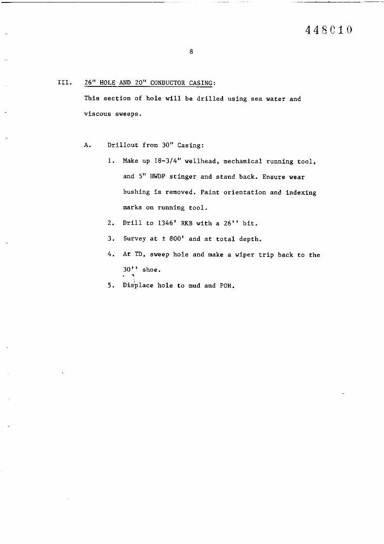
III. 26" ROLE AND 20" CONDUCTOR CASING:
This section of hole will be drilled using sea water and
viscous sweeps.
A. Drillout from 30" Casing:
1. Make up 18-3/4" wellhead, mechanical running tool,
and 5" HWDP stinger and stand back. Ensure wear
bushing is removed. Paint orientation and indexing
marks on running tool.
2. Drill to 1346' RKB with a 26" bit.
3. Survey at ± 800' and at total depth.
4. At TD, sweep hole and make a wiper trip back to the
30 '.' shoe.,5. Displace hole to mud and POR.

448G11
9
B. Drilling Mud Programme:
1. This interval of hole will be drilled with sea water
to an approximate depth of ± 1346' RKB.
2. Sweep pill volumes should be ± SO bbls at
approximately 90'-100' intervals or as hole
conditions require. Sweep at TO should be ± 200 bbl.
(See Attachment #4 for properties).
C. Casing Programme:
1. The hole will be drilled to approximately ± 1346'
RKB. This will accommodate about 24 joints of 20",
94 ppf, Grade B, Range 3 casing. Casing connectors
are Dril Quip Quik-Thread.
2. The casing string will consist of a shoe joint
\painted white with penetration stripes), and soft
line attached to guide lines, approximately 22
intermediate joints, a crossover joint, and an
18-3/4" housing joint (w/penetration stripes). Check
for proper float shoe operation before running
remainder of casing. The stab of the 20" shoe into
the 30" housing should be observed with the rig
T.V. camera.
3. While running casing, continuously fill with
seawater (maximum interval two joints).
4. Prior to making up the 18-3/4" housing joint, run a
drill pipe stinger into the casing to approximately
SO feet above the shoe using a slotted plate and
double elevator technique.

44SC1-°
10
5. Make up 18-3/4" wellhead. Recheck the running tool
make up. Lower wellhead into water and fill casing
through landing string.
6. RIR with RWDP landing string filling with seawater
as run. RIR with blocks unlocked.
7. Circulate prior to landing to check that floats are
not plugged.
8. Land 18-3/4" wellhead into 30" housing and pull
10-15 K over pick up weight to ensure that it is
latched into the 30" housing.
9. Circulate and condition hole with seawater. Cement
with ± 1500 sxs extended class 'G' cement at 12.8
ppg. Tail in with 500 sxs class 'G' at 15.8 ppg.,Displace tail slurry to within 25' of the shoe. Do
not over displace. Release the pressure and check
for back flow.
10. Release mechanical running tool by right hand
rotation.
11. POR until 15 ft. of cement stinger is inside the
wellhead. Wash the wellhead area with seawater. When
POR with stinger, do not hesitate or vessel motion
may cause stinger to damage AX ring groove.
11. POR and SLM for riser space out.

448G13
11
BOP SEQUENCE
1. Follow D.M. BOP handling procedures.
2. Use rig T.V. camera to observe landing of BOP.
3. Test BOP after landing and nippling up in accordance with
Attachment No.3.
4. Run 18-3/4" nominal seat protector.
i

12
MATERIALS 26" HOLE THRU 20" CASING
Item Quantity
26" Bit 2
Drilling jars 2
Mud materials as necessary
18-3/4" high-pressure housing w/Quik-Stab box
448G14
down & running tool
18-3/4" wear bushing & running tool
20" S-60 casing
20" Crossover (Quik-Stab pin x Quik-Thread
pin)
20" S-60 shoe joip.t.;
20" Quik-Thread (S-60) a-rings
20" Quik-Stab (NS-60) a-rings
'G' cement
Sack Bentonite
NF-l Defoamer
Power tongs and pack
20" Swage
1 + 1 B/U
1
30 jts
2
1 + 1 B/U
20 B/U
4 B/U
± 2000 sx
± 100 sx
as necessary
1
1
448G15
13
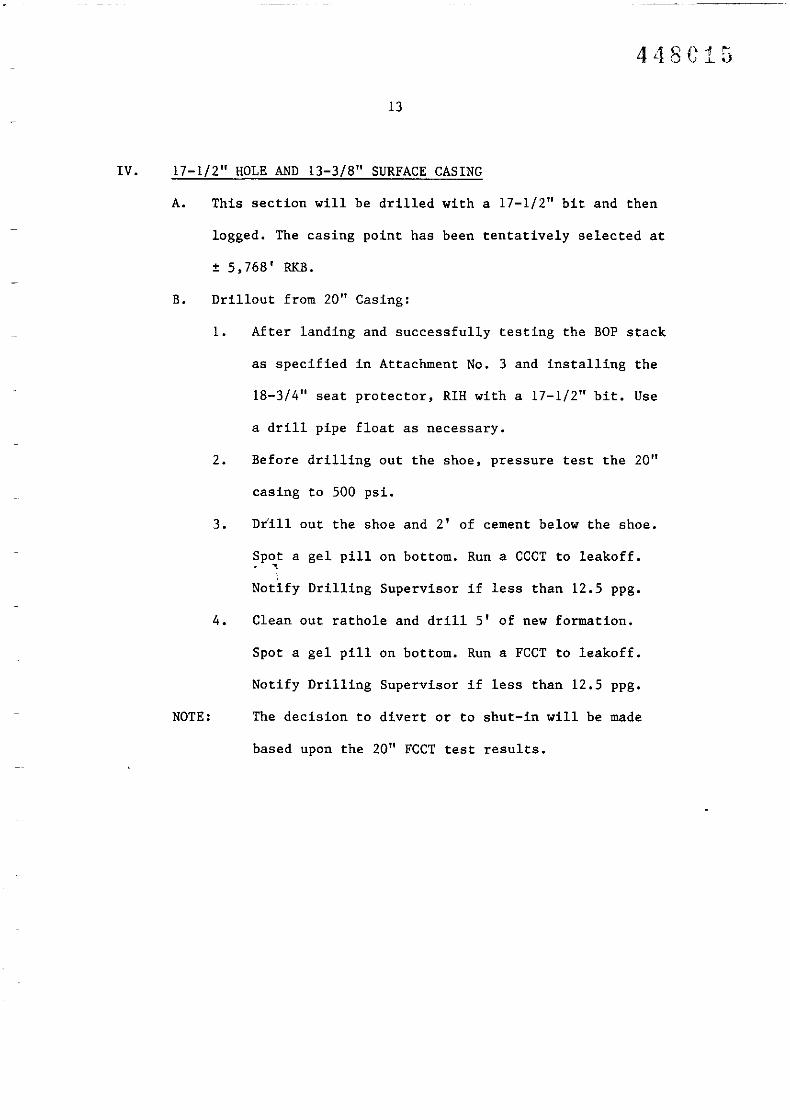
IV. 17-1/2" HOLE AND 13-3/8" SURFACE CASING
A. This section will be drilled with a 17-1/2" bit and then
logged. The casing point has been tentatively selected at
± 5,768' RKB.
B. Drillout from 20" Casing:
1. After landing and successfully testing the BOP stack
as specified in Attachment No.3 and installing the
18-3/4" seat protector, RIH with a 17-1/2" bit. Use
a drill pipe float as necessary.
2. Before drilling out the shoe, pressure test the 20"
casing to 500 psi.
3. Drill out the shoe and 2' of cement below the shoe.
Spot a gel pill on bottom. Run a CCCT to leakoff.~
Notify Drilling Supervisor if less than 12.5 ppg.
4. Clean out rathole and drill 5' of new formation.
Spot a gel pill on bottom. Run a FCCT to leakoff.
Notify Drilling Supervisor if less than 12.5 ppg.
NOTE: The decision to divert or to shut-in will be made
based upon the 20" FCCT test results.

~---------- ~
448C16
14
c. Drilling Fluid Programme:
1. For this section, a seawater, low-solids, mud system
will be used after drilling the 20" shoe and
cleaning out the rat hole.
The mud system has been designed based on the
expected formation types with emphasis on simplicity
of maintenance. It is planned to keep mud weight to
a minimum to optimize drilling rates and prevent
loss of circulation. The system is designed to keep
water loss to a minimum to prevent troublesome
shales from swelling and sloughing into the
w.nlbore.
2. The following range of mud properties is typical for~
this type of mud system.
Density 8.9-9.2 lb/gal
Yield Valve 8-20 lbs/100 sq. ft.
10 sec gel 6-15 lbs/100 sq. ft.
10 min gel 15-30 lbs/l00 sq. ft.
API fluid loss 20 cc/30 min. or less
Bentonite 20-30 ppb
Nitrate 150-250 ppm
pH 10.5-11. 0

448C
15
3. Solids control equipment must be used continuously
to keep drill solids content to a minimum.
Controlled drilling will be used if necessary and
the rate will be determined at the time. Analysis of
the types of drilled solids, as well as quantities,
will determine any additional treatment needed.
Drill solids will be controlled by the "dump and
dilute" method, employing whole mud and water
additions. Dumping should not exceed 25% of total
circulating volume per 24 hour circulating day.
4. A pH of 10.5-11.0 will be maintained for corrosion
c6ntrol.
5. Ma~netic single shot surveys should be taken on dull
bits, at total depth, or at approximately 500'
intervals. A multishot survey will be dropped prior
to POH for logs.
D. Logging Programme:
1. Prior to tripping for logs, sweep the hole with a
100 bbl viscous pill.
2. Run logs per Form 46.
3. Sidewall cores may be taken upon the wellsite
geologist's recommendations.

--------
448G18
16
E. Casing Programme:
1. A 17-1/2" hole will be drilled to a TD of :t5728' RKB
to accomodate :t 145 jnts of 13-3/8", 72 lb. /ft.,
N-80, Buttress (Drilquip No Cross).
2. Remove nominal seat protector from 20" housing.
3. Do not rely solely on average torque values for
proper make up of buttress threads. Triangular
makeup markings must be reasonably close for proper
engagement. If possible highlight makeup markings
prior to running casing. Drift all casing prior to
running.
4.' After visual inspection, make up float shoe, two
joints of casing and float collar. Check float shoe,and collar for proper operation. Use thread locking
compound to lock the float equipment and the shoe
joints. Run the remainder of the casing string, and
the casing hanger assembly.
5. Fill up the shoe joints before making up the float
collar. Rig up a fill-up line so that each joint can
be filled while the next joint is being picked up.
Make sure the casing is totally full when 13-3/8"
shoe has reached the 20" shoe. Monitor weight
indicator to make sure casing is being filled
properly. Fill running string while RIH.

44SCi9
17
7. Make up SSR (Sub-Surface Release) cementing
equipment, 13-3/8" hanger assembly and running tool,
and using 5" HWDP, land in wellhead. Rabbit landing
string as it is picked up to assure dart clearance.
Have the hanger assembly and running tool made up
prior to running casing.
NOTE:
Install full joint of D.P. between Running Tool and
SSR sub. Make up plug set after picking up hanger
and running tool.
8. Cement casing with extended class 'G' cement at 12.8
p~g. Use open hole caliper + 400' lap into 20"
casing to determine cement volume. Tail in with 500
~x 'class 'G' plus additives at 15.8 ppg. The cement
composition and Slurry Flow Plan will be provided
prior to the job.
9. Bump top plug with 2000 psi and check the float
equipment. DO NOT OVER DISPLACE. If the rig pumps
are used for displacement, verify pump efficiency
prior to job. If float equipment holds, release
running tool and flush out the wellhead. WOC time is
8 hours.
10. RIH with wash tool and thoroughly wash BOP and
wellhead area. Spot a clean gel pill in the wellhead
seal area before pulling out of hole.
11. Run and install seal assembly, and test to 5000 psi
with the drill pipe full of fluid and open to the
atmosphere.

18
MATERIALS - 17-1/2" HOLE THRU 13-3/8" CASING
Item
17-1/2" Bits & jets
17-1/2" Nearbit stabilizer
17-1/2" String stabilizer
8" Monel Drill Collar
Drilling jars
13-3/8" CIW hanger, extension and running tool
13-3/8" Seal assembly & running tool/tester
13-3/8" Wear bushing
13-3/8" Float shoe - buttress
13-3/8" Float collar - buttress
13-3/8" SSR plug, ball & dart set
13-3/8" SSR cementiiig/ball launching manifold,
Thread lock compound
13-3/8", N-80, 68 ppf, range 3, buttress casing
13-3/8", N-80, 72 ppf, R-3, buttress pup joints
13-3/8" Buttress Collar
13-3/8" Klampon thread protectors
ARI modified thread dope
13-3/8" casing drift
Single shot instrument
Multishot instrument
Power tongs and unit
'G' cement (plus additives)
Mud materials
Logging Tools
Quantity
3
2
4
2
2
2
2
2
2
2
2
2
5
± 135 jts
15 jts
4
6
7 buckets
1
1
1
2
± 2500 sx
as necessary
as necessary
448G20

PERSONNEL
Wellhead Engineer
Casing Crew
Directional Surveyor
Cementer
Divers
Mud Engineer
Logging Crew
19
448G21

-------
20
v. 12-1/4" HOLE AND 9-5/8" INTERMEDIATE CASING
A. This section of hole will be drilled with 12-1/4" bits to
±10,sOO ft RKB total depth then logged. The 9 5/8" casing
will then be run. This section of hole will be drilled with
a freshwater, low solids, deflocculated mud system with 4
ppb gilsonite and up to 0.3 ppb H.M.E •• This type mud is
designed to stabilize shales and neutralize the effects of
C02. The objective formations may be cored when encountered.
Take single shot surveys on dull bits, and at ±10,sOO ft and
approximately 500' intervals. A multishot survey will be run
at TD.
B. Drillout from the 13-3/8" casing:
1. After the BOP stack has been tested in accordance with,Attachment No. 3 and the wear bushing has been
installed, run in the hole with a 12-1/4" -drilling
assembly. Use a drill pipe float as necessary.
2. After drilling cement to within 15 ft. of the shoe,
test the 13-3/8" casing to 2000 psi.
3. Drill out the shoe and drill 2 ft. of cement. Perform
CCCT to leakoff. Notify Drilling Supervisor if less
than 13.6 ppg.

448G23
21
4. Clean out the rat hole and drill 5 feet of new hole.
Perform FCCT to leakoff. Notify Drilling Supervisor if
less than 13.6 ppg.
C. Drilling Fluid Programme:
1. For this section, a freshwater, low-solids,
deflocculated mud system will be used. The mud system
has been designed based on the expected formation
types with emphasis on simplicity of maintenance. The
system can easily be weighted up for any abnormal
pressures encountered or hole stability problems.
2. The following range of mud properties is typical for
this type of mud system.
Density. ,Yie'ld Value
10 sec gel
10 min gel
API fluid loss
HTHP @ BHT
Bentonite
Nitrate
pH
Pf
Mf
Pf/Mf
Excess Lime
8.9-17.0 lb/gal
10-25 lbs/l00 sq. ft.
4-15 lbs/l00 sq. ft.
8-30 lbs/l00 sq. ft.
10 cc/30 min. or less
20-22 cc/30 min.
20-30 ppb
150-250 ppm
11.0-12.0
1-4 mf
2-6
Less than 2
1-2 ppb

---------- .
448C24
22
3. Solids control equipment will be run in closed loop
mode. All effluents will be collected and reprocessed.
This system is designed to improve solids removal
efficiency and to minimize water dilution. All solids
will be checked with a 50 ml. retort for improved
measurement accuracy. Periodic samples will be
collected for laser particle analysis and the results
included in the final well report.
4. If an influx of C02 is detected, a scale inhibitor
will be added to protect the drill string.
D. Logging Programme:
1.
2.
3.
Upon reaching T.D. , drop multishot survey.
Make a wiper trip to the 13-3/8" casing shoe and,ret'rieve the survey.
Run logs per Form 46.
E. Coring Programme:
A core may be cut at the top of any zones with hydrocarbon
shows, using a fibreglass inner barrel.
F. Casing Programme:
1. A 12-1/4" hole will be drilled to a TD of
approximately 10,500 ft RKB to accomodate ± 260 jts of
9-5/8", 53.5 ppf, N-80, R-3 Buttress casing.

448C2G
23
2. After logging, make a wiper trip and condition hole.
3. Retrieve the 13-3/8" wear bushing.
4. Visually inspect all float equipment beforehand.
5. Make up the float shoe, followed by two joints of
casing, and the float collar. Thread lock all
connections for first three couplings. Pump through
the floats after make up.
6. Run casing, filling with mud as the next joint is
being picked up. Drift all casing prior to running.
7. Make up the SSR plug set, 9-5/8" casing hanger and
running tool and land in the wellhead using 5" HWDP.
DJ;ift 5" HWDP while running. Keep running string
full. Have the hanger and running tool made up prior
to ',starting in hole with 9-5/8" casing.
NOTE:
Install full joint of D.P. between Running Tool and
SSR sub. Make up plug set after picking up hanger
and running tool.
8. Cement program will be provided prior to the job.
9. After bumping the top plug with 3000 psi, check the
float equipment. If float equipment holds, release
running tool and flush out the wellhead. wac time is
10 hours.
10. RIH with wash tool and thoroughly wash BOP and
wellhead area. Spot a clean gel pill in wellhead
seal area before pulling the wash tool out of hole.
11. Run and install seal assembly and test to 5000 psi
with the drill pipe open to atmosphere.

24
MATERIALS - 12-1/4" HOLE & 9-5/9" CASING
Item
12-1/4" Bits and nozzles
12-1/4" Nearbit stabilizer
12-1/4" String stabilizer
12-1/4" Roller Reamer
9-5/8" Float shoe - buttress
9-5/8" Float collar - buttress
9-5/8", 53.5 ppf, N-80, R III, buttress casing& pups
9-5/8" Buttress Collars
9-5/8" casing hanger & pup w/running tool
9-5/8" seal assembly w/running test tool
9-5/8" wear bushing. ,8" Monel drill collar
Drilling jars
Coring equipment - lot
9-5/8" Surface release head
9-5/8" Klampon thread protectors
9-5/8" Circ. Swedge
9-5/8" Casing drift
API modified thread compound
9-5/8" casing scraper with spare blocks
Power tongs & pack
Mud materials
Cement
Single and multishot instruments
Logging Tools
Quantity
as necessary
3
9
2
2
2
± 290 jts
6 jts
2
2
2
2
3
1
2
6
1
1
12
1
2
as necessary
± 3500 sx
1 each
as necessary
448C2G
PERSONNEL
Casing Crew
Core Hand
Wellhead Engineer
Mud Engineer
Surveyor
Cementer
Logging Crew
2S

448C28
26
V. 8-1/2" HOLE AND 7" CASING OIL STRING
A. This section of hole will be drilled with 8-1/2" bits to
±14,073 ft RKB total depth then logged. The liner will be
run if testing is indicated. This section of hole will be
drilled with a freshwater, low solids, deflocculated mud
system with 4 ppb gilsonite and up to 0.3 ppb H.M.E •• This
type mud is designed to stabilize shales and neutralize the
effects of C02. The objective formations may be cored when
encountered. If productive formations are encountered, the
formation may be drill stem tested after 7" liner is set.
Take single shot survey on dull bits, and at total depth and
apptoximately 500' intervals. A multishot survey will be run
at TD.
B. Drillbut from the 9-5/8" casing:
1. After the BOP stack has been tested in accordance with
Attachment No. 3 and the wear bushing has been
installed, run in the hole with a 8-1/2" drilling
assembly. Use a drill pipe float as necessary.
2. After drilling cement to within 15 ft. of the shoe,
test the 9-5/8" casing to 2000 psi.
3. Drill out the shoe and drill 2 ft. of cement. Perfo~
CCCT to leakoff. Notify Drilling Supervisor if less
than 17.0 ppg.
448C29
27
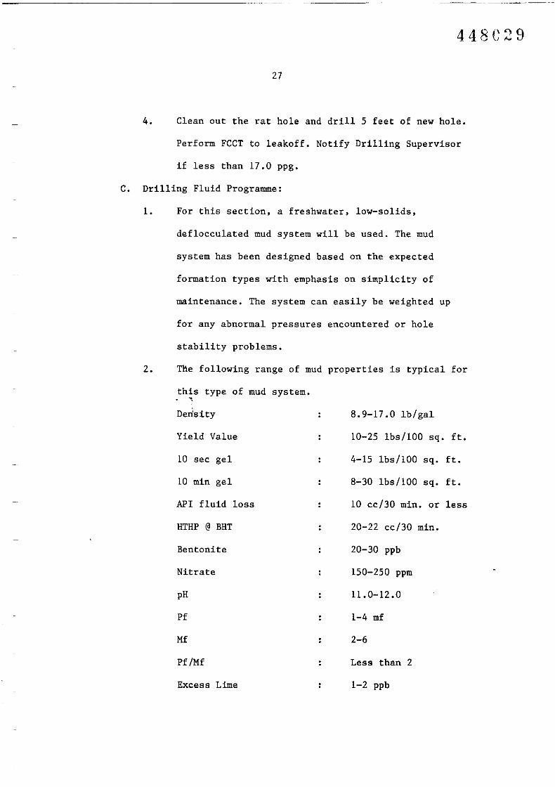
4. Clean out the rat hole and drill 5 feet of new hole.
Perform FCCT to leakoff. Notify Drilling Supervisor
if less than 17.0 ppg.
C. Drilling Fluid Programme:
1. For this section, a freshwater, low-solids,
de flocculated mud system will be used. The mud
system has been designed based on the expected
formation types with emphasis on simplicity of
maintenance. The system can easily be weighted up
for any abnormal pressures encountered or hole
stability problems.
2. The following range of mud properties is typical for
this type of mud system.. ,Derlsity
Yield Value
10 sec gel
10 min gel
API fluid loss
HTHP @ BHT
Bentonite
Nitrate
pH
Pf
Mf
Pf/Mf
Excess Lime
8.9-17.0lb/gal
10-25 lbs/100 sq. ft.
4-15 lbs/100 sq. ft.
8-30 lbs/100 sq. ft.
10 cc/30 min. or less
20-22 cc/30 min.
20-30 ppb
150-250 ppm
11.0-12.0
1-4 mf
2-6
Less than 2
1-2 ppb

448C30
28
3. Solids control equipment will be run in closed loop
mode. All effluents will be collected and
reprocessed. This system is designed to improve
solids removal efficiency and to minimize water
dilution. All solids will be checked with a 50 mI.
retort for improved measurement accuracy. Periodic
samples will be collected for laser particle
analysis and the results included in the final well
report.
4. If an influx of C02 is detected, a scale inhibitor
will be added to protect the drill string.
D. Logging 'Programme:
1. Upon reaching T.D., drop multishot survey.. ,2. Make a wiper trip to the 9-5/8" casing shoe and
retrieve the survey.
3. Run logs per Form 46.
E. Coring Programme:
A core may be cut at the top of any zones with hydrocarbon
shows, using a fibreglass inner barrel.
F. Casing Programme:
1. A 8-1/2" hole will be drilled to a TO of
approximately 14,073 ft RKB to accomodate ±120 jnts
of 29 ppf, N-80 buttress liner.

448G
29
2. After logging, make a wiper trip and condition hole.
3. R/U and run the 7", 29 ppf, N-80 Buttress liner.
4. Visually inspect all float equipment beforehand.
5. Make up the float shoe, followed by two joints of
liner, and the float collar. Thread lock all
connections for first three couplings. Pump through
the floats after make up.
6. Run liner, filling with mud as the next joint is
being picked up. Drift all liner prior to running.
7. Make up the TIW Hydro hanger and running tool and
set liner at TD with ± '300 ft overlap inside 9-5/8"
casing using drill pipe. Drift 5" drill pipe while
r~nning. Keep running string full. Have the hanger
and running tool made up prior to starting in hole
with 7" liner.
8. Cement program will be provided prior to the job.
9. After bumping the top plug with 3000 psi, check the
float equipment. If float equipment holds, release
running tool, POOH, and flush out the wellhead. WOC
time is 10 hours.
10. RIH with wash tool and thoroughly wash BOP and
wellhead area.
11. RIH with cleanout assembly and cleanout 7" liner.
Test liner lap to 1 ppg over 9-5/8" FCCT.

30
G. Testing
Zones identified as potentially productive will be tested.
A DST procedure will be developed by the engineering
staff.
H. Plugging and Abandonment
After being fully evaluated for potential production, the
well will be plugged and abandoned according to Petroleum
(Submerged Lands) Act 1967, Directions as to Drilling
(1 June 1980).
A detailed programme will be furnished to the rig prior to
commencement of P & A operations.

PERSONNELCasing CrewCore HandTIW EngineerMud EngineerSurveyorCementerTesting CrewsnST CrewLogging Crew
31
448G33

32
MATERIALS - 8-1/2" HOLE & 7" LINER
Item
8-1/2" Bits and nozzles
8-1/2" Nearbit stabilizer
8-1/2" String stabilizer
8-1/2" Roller Reamer
7" Float shoe - buttress
7" Float collar - buttress
711, 29 ppf, N-80, R III, buttress casing
& pups
7" Buttress Collars
7" TrW Liner hanger w/ running tool
7" TrW Polished slick jt
6-1/2" Monel drill collar
Drilling jars'
Coring equipment - lot
7" Surface release head
7" Klampon thread protectors
7" Circ. Swedge
7" Casing drift
API modified thread compound
29 ppf liner scraper with spare blocks
Polished Mill for PBR tie back sleeve
Power tongs & pack
Mud materials
Cement
Single and multishot instruments
Logging Tools
DST Tools
Quantity
as necessary
3
9
2
2
2
± 127 jts
6
2
2
2
3
1
2
6
1
1
12
1
2
2
as necessary
+ 3500 sx
1 each
as necessary
as necessary
448G3 fl

33
MATERIALS - 8-1/Z" HOLE AND 7" LINER
(Clean Out Assembly)
Item Quantity
4-3/4" Spiral Collars ZO
3-1/Z" S-135 Drill Pipe 5000 ft
6" String Stabilizers Z
6" Bits 3
5-7/8" bits Z
4-1/Z" IF Box x 3-Y/Z" IF Pin XO Z
4-3/4" Drilling Jars Z~

A~ AlISTMAI.IA 1'J-:ll{CII.tII't Ct",I'A:-lY 448C36
_ _ ,_-:P~EL::'::;CAN:::... _II! liriS
.uU &ASS BASile T-22P
IU .... ..:4~0~O _
DATI Dt:CEI1Il~:R
WI" HO._...2. D' _
ORIlUNG AND COHPlrnON 'ROGMI1
AUSTRALIA
ATTACHMENT # 1
IOCtWQll SEISMIC lINE t/'IK - 87 S.P. 240 (40 DECItUS 20' 4J.sa" SOtfI'H lAT1TUD£. 145 DECREES st' 49.21" EAST IJ)fIiG[TU~)
EASTERN VIEW CROUP LATE EOCENE TIlRU LATE ClETACEOUS (5798 14 07] RXII), -MIIItOO O' DIIa6G ."IOXIMATI om". 0' OtolOGICAl "Ames
nNTOOU DUTH IHTU,...""UTII1AUD .UV"TION
ROTARY SEABED TO T .0. "'''''KIA I Dim< I WVATIC»414,000 55TORQUAsl CROt./P (Sn JottOll) l26 ... 2SJ' 55
WIOAlSUlW'lt 00t0fi BUIFF (Top Eocene) "" RK. SlSO' 55*EASTEIUI VIEW CROUP 5798 RKI 5725' SSn," DirTH INT••V...L. ITC.*WIthin Lower Eocene 16D ... 7540' SS
lSF-8HC-GR-5P-CAL (C R TO SEABED) D46' - 5725 ' SS *\Ilthln Lower PilleQCene 12,87) W 12,800' SSISF- SHe -CR- SP· (MSFl./CAL) H2S' - 14000' 55l.DT-CNT sns' - 14000' 55HOT (D46'· 5725' 5S If REQUIRED) sns' . 14000' 55VSP (oPTIONAL) 1346' . 14000' 55CST (LJ46' - 5725' SS IF RIQUIRIO) 5725' - 14000' 55
TOT"'l Of"H 110,07) "". 110,000' SS......... • POISI,U 'AT # ,..O.....u COI1~inoN INTUV"'L
D"U CUTlV'tG iAMNS DlIWHG TaMISI~;CL£ SIiOT SURVEYS ON TRIPS EVERY 500' - LOGS 1'0 BE RUN K[ '''"QU"NCY DinH iNTIAVAL ''''QUiNCY DUTH INTIAV"'l13 l/8" AND <) S/S" esc DEPTHS AND AT r.D. AND IN TIlE INTERIM AS
32.S' (lOH) 13106 ' - S42]' RKB (6 SETS) WA5KED & DRIEDRIQUIR£D TO EVALUATE fOAAAtION5 BEING DIULLED.32.S' (10l'l) 1346' • S421' RKI (2 SETS) WET OOHPOSlI£ CLOTH BAC18.4'
( "" S42l' - 5798' RKA (6 SETS) WASKED & DRIED32.8' ( 10K) 542l' - 5798' RXS (2 SETS) WET com'OSiTE CLOTH BAC
$PKW. TIn 9.8' ( 311) 5798' -11007)' RKB (6 sns) WASItED ~ DRIEDn" DIPTH INTI.v...... (fC. Z9.5' ( 9H) 5798' -1407)' RQ <:z SITS) 10'£1' OOHPOSITE CLOtll BAt
29.5' ( 9H) 579il' -1407)' RKB (l SET ) WET COHPOSITE CA.\I~ED
m's AS RIQUIREDOST'S AS REQUlRE.D
"""""........nt£ ABOVE OOHFORHS WIlli REQUIRD1EHTS Of tHE
tHE [)[CISION 10 TESI THE HOLE WILL SE USED OH ENCOlI'RACEHENl' F1O'I t«JD PETltOLEtm (SUI.'lERC[D UJlDS) ACt, 1967, CLAUSE 110ux; SHC).lS AND WIRELlNE ANALYSIS. nt£ RIC WILL !£ EQUIPPED TO COfiDllCtRF!'S AND CONVENTIONAL DSl'S IHROUGH CASIttC.
, -
MUD NaG""".t.waOJu......n ....n.VAl
HI. 1)1,6' RKJIJ4.6' 5768' RKJ5768' 1407J' RK8
TYI'f. I1UD WIICHT # ICAl VlseOSHY SiC. "'" w. L CC/)OI1 OTHo. SHe"ICATiONS
SEAII.\IER ~ W/VISaxsS SWEEPSS\o//CEL 8.9 - 9.2 4S 55 20 Oft LESS YV 8 - 20. JHi 10.5 - U.OF\I/CEL 8.9 - 17.0 4S 55 10 OR LESS YV 10· lS, pH 11.0 - 12.0
hIHP 20 - 22
........PROPERtiES OF l«1D SYSTtH AJtE DESCRIBED IN THE DEIAILED OPERAI'IOtfS PLAN.
H'I.-l.P 10 8[ RUN F1lOH 7000' 1'0 T.D. At 8Hl' (CRAOIEHT • Z.O· F/l00' IF NO OIHER. DAtA AVAIUIU)
~ PlOGIAM~ $TAING UT. DIn... C...SINC SIU' HOLi Sill' sx. CII1INT n" C(J"l(NT DISC!UP'TIQN Of l4NQUtoK; l"OINT. ITC.
CQO<OUCTO& ..,, ... >0" J6" 2000 CUSS 'c' + ADDITIVES
su"...ct 1326' ... 20" 26" 2000 cuss 'c' + ADDITII/ES
INTlMiD'A.TI 5786' W 1] 3/S" 17 1/2" BY CALIPER CU.SS 'c' + ADDIlll/ES
"" "'lING 10500' W 9 5/8" 12 1/10" BY CALIPER CLASS 'c' + AOOITlVESUHIA CA51NC 11001]' RKI 1" 8 1/2" BY CALIPER CU.SS 'c' + AI)DIIIYf;S........
1. AU CASH~ POIHTS ARE lE."fTAIlI/[2. CDlEHI COMPOSITIONS 1'0 BE U.B lISTEDl. 30" AND 20" CASINC TO BE CE!£NTED BY INNER StRINe HE'!lIOD
.. HQ.,....L. THI TUWlA.. GOODS ALLOCATION lEfTU S'lelfliS CASI~ SiZIS TO "uno. HOU SIZES Will II COVIANIO aY CON'....CT.
COI.IHG rlOGI4M
OOHVDi"IION.\L CORlS 10 I«JR£ ntOROUCHLY HfV£STICAIE SHOWS .vm J'()T£.Tt1AL RESERVOIR ROCKS WIU BE CI1t IF DRILLING cotiDI lllONS PEk.'l1T UPOrC TIlER£aNIE.'UMlIONS OF THE WELLSITE CEOLOCIST WID! CONClJR.lWtC£ OF AKlCO'S SYDtiEY OFFICE, SI~AlL CORES WILL BE TAKEN IN SHALES A."iO OTIiERfOR.'lAlIONS OF l~-rEREsr BlLOW S1!S' SS FOA PALYNOI..OCY. CEOCHEMISTRY AN~ LlntOLOCICAL DATA. NOTE REQUIRE.'tENTS OF PETROUUH (SUB.'tEIlGED UIfDS)ACT, 19c7. CLAUSE l~.
A1Il1IOfllS£D COHPlrnOfC PRClCRAH WILL ar: FUJUUSHED Of( DECISION 1'0 rottPLElE WELL.
GleeaAl ......,
ALL I/ALUES RfPOATtD 10 COYEIOO1[H'r MUst 8E IN HEnlC UNITS.
_..._-__" .:;u_t_.4R_c:__I--.__. =...,....~....,.,,__---1 _-__"'_D_,_===-=-== _J. C. IWiKIN/I. \o'HE.E.LER
......~ _.. _ .

ATTACHMENT H 2 448C37
DRILLING GRAPH30
DRILLING TIME (DAYS)
10 20o0
FEET I DAYDRILLING PROGRESS IN
I•. Mud - FIELD T-18P WELL NAME PEUCAN 5
I•. Water - PROJECTED T.O. lltq(Xl5S FORMATION LCRET1 '. MUD SEAWATEIi> GEL ML TO ~ 57913'
ment ;
. P,e... rJ FRESHWATER GEL ,579& TO TO+i •
L. CSG. 30" IIJi 20' 1326'ring 1J -r-
@ , @
2, 40 13 3/e" @ 5;766 95/6" @ 10,500
ill Pip. Lt, ;
- EPOCH DIAMOND MRIG CONT'R.II St.m T••I
I
- ,
+~GRND. EL. 73 ROB. WL. SEABED
h For , -tt 219 2923
' , WL. MUOLINE ROB. ML.,-rk- ~ H-H-:-~~
..
• CuI Mud 4'1=.......... ....f..-+' EST. COST (GROSS) US $1\465,647·
I~h- •..-- Hn ·f-l.. ;::m
CuI Mud' ,
REMARKS AlL DEPTHS ARE, <=Hm- , RK81', -.,... -j-.
g lock ,50
25 OAYS TESTING4
, , , . , . , , . I ,, I' • l±i::i I ipair Rig, I 4 DAYS PiA AND ANCHORS, ,
H· I , i@ 14,000'.track
, , , ,'~~I , ,
, ,, . '~1i. Press. 60 70 805
, , , , . ,I
s of Cire. ..H--l.. - T'-,
I I-,-..... ,.-
I
, .
6, , I
, I ,
, ,
- - ~
I
7,
- ,-
, .. ,, ,
12· 8I
, .,-I
I' rt:-
,I I ,, I I • I I, I I' , ,
13 . 9, I , .
I I I ,I , , .. ,-,
", . -,-, , ..,
14 10
-- .
15 11--- 11 t
1+16 12 -
I •
'"ozc(
'":;)o::a::...::a::...
'0...o
;:;............o
Plu
Oil
Go
C.
Fis
Ib
Ib
)ATE
S- Drj
,. Tbg
It Ro
C Lo.
DI Sid
1'- C.g
'" Co
Dr
WElL NAME _~P..!::E:.!::L~IC:I::.All.:N!........!..N~o:....:5~_

ATTACHMENT II 3
BOP TEST REQUIREMENTS
Australian regulations specify the following BOP equipment test requirements:
BOP AfterInstallation
Prior toCsg.Drillout
FollowingDisconnectionof Pressure Weekly
SealsTrip
RelatchLMRP
Connector,Choke & KillLines 5,000 psi 5,000 psi 5,000 psi 5,000 psi N/A 5,000 psi
Annular 70% Rating 70% Rating 70% Rating Function N/A Connectionto
3,500 psi
Pipe Rams 5,000 psi 5,000 psi 5,000 psi 5,000 psi Function Function,
Shear & Function Min 70% Function Function Function FunctionBlind Rams
The regulations additionally require that all such tests be recorded in thedrillers log. (IADC report)
448C39
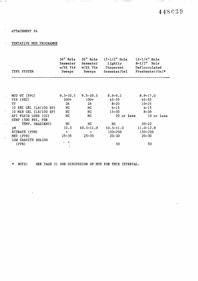
ATTACHMENT 1/4
TENTATIVE MUD PROGRAMME
TYPE SYSTEM
36" HoleSeawaterw/Hi Vis
Sweeps
26" HoleSeawaterw/Hi Vis
Sweeps
17-1/2" HoleLightly
DispersedSeawater/Gel
12-1/4" Hole8-1/2" HoleDeflocculatedFreshwater/Gel*
MUD WT (PPG) 9.5-10.5 9.5-10.5 8.9-9.2 8.9-17.0VIS (SEC) 100+ 100+ 45-55 45-55YV 26 26 8-20 10-2510 SEC GEL (LB/l00 SF) NC NC 6-15 4-1510 MIN GEL (LB/l00 SF) NC NC 15-30 8-30API FLUID LOSS (CC) NC NC 20 or less 10 or lessHTHP (500 PSI, PER
TEMP. GRADIENT) NC NC NC 20-22pH 10.5 10.5-11.0 10.5-11.0 11.0-12.0NITRATE (PPM) ~ 150-250 150-250MBT (PPB) 25-35 25-35 20-30 20-30LOW GRAVITY SOLIDS
(PPB),
50 50
* NOTE: SEE PAGE 21 FOR DISCUSSION OF MUD FOR THIS INTERVAL.

--------- ------
448{>lO
ATTACHMENT 115
TENTATIVE CASING PROGRAMME
SETTING DEPTH (RKB)
HOLE SECTION
WT
GRADE
30"± 641'
ML-TD
1.0" WALL
B
20"± 1,326'
ML-TD
94 PPF
B
13-3/8"± 5,728'
ML-TD
72 PPF
N-80
9-5/8"± 10,500'
ML-TD
53.5 PPF
N-80
7"± 14,043'
± 10,200' Tn
29 PPF
N-80
CONN D.Q. QUIK STAB D.Q. QUIK STABTHREAD
D.Q. NO CROSSBUTT BUTT BUTT
The following is a recommended practice for proper casing hanger landoutand measurement.
1. Secure a length of steel 0.092 wire to the outer barrel of theslip joint. Space out the wire through the rig floor as near tothe rotary as possiale. Secure tied off line in a safe place.
2. RIH with the casing hanger landing string and latch into wearbushing. Function pipe ram on painted joint for surfacemeasurement. Mark landing string and 0.092 wire on rig floor. POHwith wear bushing.
3. Calculate proper surface measurement differential between 0.092wire and marked landing joint for casing hanger landout.
4. RIH with casing and land casing hanger in wellhead. Check forproper 0.092 wire/landing joint measurement on rig floor. Functionpipe ram on painted joint for surface calculation of casing hangerlanding depth.
5. Cement casing as per program.
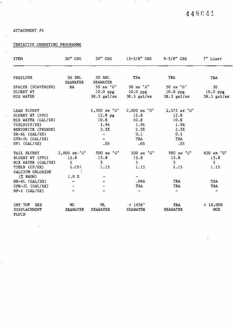
ATTACHMENT 1/6
TENTATIVE CEMENTING PROGRAMME
ITEM 30" CSG 20" CSG 13-3/8" CSG 9-5/8" CSG 7" Liner
PREFLUSH 50 BBL 50 BBL TBA TBA TBASEAWATER SEAWATER
SPACER (SCAVENGER) NA 50 sx 'G' 50 sx 'G' 50 sx 'G' 30SLURRY WT 10.0 ppg 10.0 ppg 10.0 ppg 10.0 ppgMIX WATER 38.3 gal/sx 38.3 gal/sx 38.3 gal/sx 38.3 gal/sx
LEAD SLURRY 1,500 sx 'G' 2,000 sx 'G' 2,575 sx 'G'SLURRY WT (PPG) 12.8 pg 12.8 12.8MIX WATER (GAL/SX) 10.8 10.8 10.8YIELD (CF/SX) 1.94 1.94 1.94BENTONITE (PREHYD) 2.5% 2.5% 2.5%HR-6L (GAL/SX) 0.1 0.1CFR-2L (GAL/SX) TBA TBANfl (GAL/SX) .05 .05 .05
TAIL SLURRY 2,000 sx.-'G' 500 sx 'G' 500 sx 'G' 500 sx ' G' 620 sx 'G'SLURRY WI (PPG) 15.8 15.8 15.8 15.8 15.8MIX WATER (GAL/SX) 5 5 5 5 5YIELD (CF/SX) 1.·15~ 1.15 1.15 1.15 1.15CALCIUM CHLORIDE
(% BWOW) LOXHR-6L (GAL/SX) .066 TBA TBACFR-2L (GAL/SX) TBA TBA TBANF-1 (GAL/SX)
CMT TOP RKB ML ML ± 1056' TBA ± 10,000DISPLACEMENT SEAWATER SEAWATER SEAWATER SEAWATER MUDFLUID

ATTACHMENT 1/7
TENTATIVE LOGGING PROGRAMME
17-1/2" HOLE
RUN III ISF-BHC-GR-SP-CAL (GR TO ML)
12-1/4" HOLE & 8-1/2" HOLE
RUN III ISF-BHC-GR-SP-CAL
RUN 1/2 LDT-CNT
RUN 1/3 HDT (1,326'-5,768' IF REQUIRED)
RUN 1/4 VSP (OPTIONAL)
RUN 1/5 CST (1,326'-5,768' IF REQUIRED)
NOTES:
1- Provision- w~ll be made to run RFT if required.

ATTACHMENT 118
PLUG REQUIREMENTS FOR P & A
Application
Uncased Hole
CementTop of Cmt. Bottom of Cmt.
Equipment & Remarks
Oil & GasZones
Fresh WaterZones
WorkableMinerals
Cased Hole
w/Open HoleBeloww/Open HoleBelow
w/Open HoleBelow &Possible LostCirc.
Open Perfs
100' Above Zone
100' Above Zone
300' Above Zone
100' Above Shoe50' AboveRetainer
50' AboveBridge Plug
100' Be low Zone
100' Below Zone
300' Below Zone
100' Below Shoe
100' Be low Shoe
Top of BridgePlug
No Cmtg. Equip. Reqd.
No Cmtg. Equip. Reqd.
Contact Director ofMines for Definitionof Workable Minerals
No Cmtg. Equip. Reqd.Cmt. Retainer 100'to 50' Above Shoe.
Permanent BridgePlug 0' to 100'Above Shoe
Cmt Plug 100' AboveTop ofInterval
w/Bridge Plug 50' Above B.P.
100' BelowBottom ofInterval
Top of B.P.
No Cmtg. Equip. Reqd.
Bridge Plug 0'-150'Above Interval Note:Perfs must beisolated from Below
Mise
Casing Stubs 100' Above 100' BelowCasing Casing
Liners 100' Above 100' AboveLiner Top Liner Top
Annular Space As Reqd. As Reqd.
Surface Plug 0'-150' Variable(inside Below Sea Floorstring)
Retainer Optional
Retainer Optional
Not Reqd If Space NotOpen to Uncased HoleMust Be at Least150' Long

ATTACHMENT II 9
RECOMMENDED HYDRAULICS
26" HOLE 17-1/2' 'HOLE 12-1/4" HOLE
----_._--
448G44
8-1/2" HOLE
Maximum SurfacePressureFlowrateJets
AV's (DC/DP)HHP/sq in
2200 psi±1240 GPM3 x 22
50/47 Ft/Min1.3
3000 psi±850 GPM3 x 16, C-14(TFA = .75)86/74 Ft/Min
2.3
3000 psi±560 GPM2 x 12, 13, C-ll(TFA = .444)159/110 Ft/Min
3.9
3000 psi± 350 GPM12-13-14(TFA = 0.38)237/182 ft/min
4.1

ATTACHMENT II 10
TENTATIVE B.H.A.PROGRAM
36" and 26" Hole
Type SliekMax. O.D. 8"Survey Type Toteo
8" Monels Nonerequired
Float Sub Yes wIrequired Weep hole
Junk Sub NIA
17 1/2", 12-1/4", 8-112" Hole
60 Ft. pendulum8"
Single shot andmulti-shot
1
Yes wIWeep hole
Prior to Coring
NOTE: 26" Stabilizer will be available on rig and to be run as required.

J )
5cm
...0 ..... '
.,.
...
5
0'..... ••·
T/14P
.;......
I.
...............ee.,..._-·-.-...·-e-..._.·--.-_ ....- ....-.-....· .. -. _---· -- .......................................· .......---....----
....
...

ATIACHMENT # 12
448C47
•Ama P!alb:Iian C'.aIl.-r-.--.....---5cm
PELICAN-' WELL PROGNOSIS
N:TUAL Pll£OlCTEO0 - ,.
~.." l.'" - ...-.. -
~ !_...... - ...to j.. -" !
-~ - ...-......::: ~---~
-N- -..- ~ •
0 ... -• z
"...v- 0
"...
.....- ... -~
..... •.. ~...- .~
c- ...... ~
::t:~ .....- ....... z~-~
...~.. ... Ml_
C ..,,- 0 cv ..
,-,.- -- "'-•..;., ...- :; ,.tD ... .....
~
0...- vC~...•z v- •...~~- ...
c ....-I I
.'.
.-
loG OIAMONG III lPOCMU1n.
7Ht
lASS IASIN. AUSUALIA
PfUCAN-S PIOONOSIS
TNIC-U SHOf POINT 2~O
-- ,1'-- ,- ..·..u,..... ~....~ .......... ... ~.

ATTACHMENT II 13
TENATIVE SAMPLE COLLECTION
DEPTH
410.3 m - 1653.0 m(1346 - 5423 ft)
1653.0 m - 1767.3 m(5423 - 5798 ft)
1767.3 m - 4289.5 m(5798 - 14,073 ft)
. ..
FREQUENCY
10m(32.8 ft)
5 m(16.4 ft)
10 m(32.8 ft)
3 m( 9.8 ft)
9 m(29.5 ft)
------ ~~-~~~
448C48
DESCRIPTION
6 sets washed and dried2 sets wet composite.cloth bag
6 sets washed and dried
2 sets wet composite,cloth bag
6 sets washed and dried
2 sets wet composite.cloth bag
1 set wet composite,canned


