An Atom-Probe Tomographic Study of Arc Welds in a Multi-Component High-Strength Low-Alloy Steel ALLEN H. HUNTER, JEFFREY D. FARREN, JOHN N. DUPONT, and DAVID N. SEIDMAN An experimental plate steel with the composition Fe-1.39Cu-2.7Ni-0.58Al-0.48Mn-0.48Si- 0.065Nb-0.05C (wt pct) or alternatively Fe-1.43Cu-2.61Ni-1.21Al-0.48Mn-0.98Si-0.039Nb- 0.23C at. pct has been recently produced at Northwestern University for use in Naval hull and deck applications—it is designated NUCu-140. To understand the microstructural changes occurring in NUCu-140 steel after gas-metal arc welding (GMAW), a detailed study of the heat- affected and fusion zones was performed throughout the weld cross section using micro- hardness, metallographic, chemical, and atom-probe tomographic analyses. Local-electrode atom-probe (LEAP) tomography was employed to measure the morphology and compositions of Cu-rich precipitates from each region. The mean radius, number density, volume fraction, and compositions of the precipitates, as well as the interfacial concentration profiles, are measured. The Cu precipitates dissolve partially from the heat-affected zone (HAZ) thermal cycle, and freshly formed sub-nanometer radius Cu-rich precipitates nucleate in both the HAZ and fusion zone (FZ) during cooling; however, the precipitation of Cu during cooling in the HAZ and FZ is not sufficient to restore the lost strength. The precipitation in the FZ is reduced compared to the HAZ due to a mismatched Cu composition of the weld. Multi-pass welding is suggested to restore strength in the GMAW sample by promoting Cu precipitate nucleation and growth in the HAZ and FZ. DOI: 10.1007/s11661-012-1518-5 ȑ The Minerals, Metals & Materials Society and ASM International 2012 I. INTRODUCTION HIGH-STRENGTH low-alloy (HSLA) steels repre- sent an important class of alloys that are used for a variety of structural applications. Modern HSLA steels, such as HSLA-100, contain a low carbon concentration of < 0.05 wt pct, for both simplified welding and enhanced low-temperature toughness, and they achieve their strength through precipitation strengthening. Using appropriate heat treatments, the HSLA steels easily achieve yield strengths of > 690 MPa (100 ksi), while maintaining ductility and fracture toughness. [1] Recently, several variations of HSLA steels have been developed at Northwestern University for direct substi- tution of existing HY60, HY100, and HSLA-100 steels used currently in naval applications. [2–12] These alloys, designated as NUCu-X, where X refers to the alloy yield strength in ksi, include NUCu-70, NUCu-140, and NUCu-170 steels. NUCu-70 is fabricated via hot rolling and the composition is designed to co-precipitate NbC and Cu-rich precipitates during air cooling. In addition to Nb and Cu, Ni is added to reduce hot-shortness cracking during hot rolling caused by insoluble Cu, [13] Mn is added for solid-solution strengthening and to getter S in MnS inclusions, and Si is added for additional solid-solution strengthening. [5–12] NUCu-70 is classified under ASTM Standard A710 as alloy ‘‘Grade B’’ [14] and is currently utilized in bridge con- struction. [8] To increase the yield strength of NUCu-70 above 70 ksi, additional Ni, Al, and Nb are added to the composition to increase both the volume fraction of precipitates and the precipitation strengthening poten- tial. The alloy, designated as NUCu-140, is solution treated and aged for 2 hours to achieve the required yield strength. [2–4] The Cu precipitation strengthening of the NUCu-X series of alloys has an additional benefit of increasing the low-temperature toughness compared to Cu precipitate-free alloys (e.g., HSLA-65). The Cu precipitates increase the dislocation activation volume by approximately a factor of three and subsequently reduce the temperature dependence of the flow stress, leading to improved toughness at low temperatures. [15] A third NUCu composition has an increased yield strength of 170 ksi, achieved by increasing the Cu concentration to 2.09 wt pct. [4,16–18] NUCu-170 dis- plays, however, a significantly reduced toughness, < 14 J (10 ft-lbs) at 253 K (20 ŶC), which is attributed to its high P concentration. [19] Current research at Northwestern University focuses on further develop- ment of the NUCu-140 composition, which will directly compete with HSLA-100 and HSLA-115 Naval steels. A large number of analytical techniques are employed for studying precipitation in Fe-Cu and Fe-Cu-Ni alloys, spanning several decades of research. Some examples of ALLEN H. HUNTER, Ph.D. Candidate, and DAVID N. SEIDMAN, Walter P. Murphy Professor, are with Northwestern University, Evanston, IL. Contact e-mail: [email protected]JEFFREY D. FARREN, Ph.D. Candidate, and JOHN N. DUPONT, Professor, are with Lehigh University, Bethlehem, PA. Manuscript submitted February 23, 2012. Article published online November 10, 2012 METALLURGICAL AND MATERIALS TRANSACTIONS A VOLUME 44A, APRIL 2013—1741
Transcript
An Atom-Probe Tomographic Study of Arc Weldsin a Multi-Component High-Strength Low-Alloy Steel
ALLEN H. HUNTER, JEFFREY D. FARREN, JOHN N. DUPONT,and DAVID N. SEIDMAN
An experimental plate steel with the composition Fe-1.39Cu-2.7Ni-0.58Al-0.48Mn-0.48Si-0.065Nb-0.05C (wt pct) or alternatively Fe-1.43Cu-2.61Ni-1.21Al-0.48Mn-0.98Si-0.039Nb-0.23C at. pct has been recently produced at Northwestern University for use in Naval hull anddeck applications—it is designated NUCu-140. To understand the microstructural changesoccurring in NUCu-140 steel after gas-metal arc welding (GMAW), a detailed study of the heat-affected and fusion zones was performed throughout the weld cross section using micro-hardness, metallographic, chemical, and atom-probe tomographic analyses. Local-electrodeatom-probe (LEAP) tomography was employed to measure the morphology and compositionsof Cu-rich precipitates from each region. The mean radius, number density, volume fraction,and compositions of the precipitates, as well as the interfacial concentration profiles, aremeasured. The Cu precipitates dissolve partially from the heat-affected zone (HAZ) thermalcycle, and freshly formed sub-nanometer radius Cu-rich precipitates nucleate in both the HAZand fusion zone (FZ) during cooling; however, the precipitation of Cu during cooling in theHAZ and FZ is not sufficient to restore the lost strength. The precipitation in the FZ is reducedcompared to the HAZ due to a mismatched Cu composition of the weld. Multi-pass welding issuggested to restore strength in the GMAW sample by promoting Cu precipitate nucleation andgrowth in the HAZ and FZ.
DOI: 10.1007/s11661-012-1518-5� The Minerals, Metals & Materials Society and ASM International 2012
I. INTRODUCTION
HIGH-STRENGTH low-alloy (HSLA) steels repre-sent an important class of alloys that are used for avariety of structural applications. Modern HSLA steels,such as HSLA-100, contain a low carbon concentrationof <0.05 wt pct, for both simplified welding andenhanced low-temperature toughness, and they achievetheir strength through precipitation strengthening.Using appropriate heat treatments, the HSLA steelseasily achieve yield strengths of >690 MPa (100 ksi),while maintaining ductility and fracture toughness.[1]
Recently, several variations of HSLA steels have beendeveloped at Northwestern University for direct substi-tution of existing HY60, HY100, and HSLA-100 steelsused currently in naval applications.[2–12] These alloys,designated as NUCu-X, where X refers to the alloy yieldstrength in ksi, include NUCu-70, NUCu-140, andNUCu-170 steels. NUCu-70 is fabricated via hot rollingand the composition is designed to co-precipitate NbCand Cu-rich precipitates during air cooling. In additionto Nb and Cu, Ni is added to reduce hot-shortnesscracking during hot rolling caused by insoluble Cu,[13]
Mn is added for solid-solution strengthening and togetter S in MnS inclusions, and Si is added foradditional solid-solution strengthening.[5–12] NUCu-70is classified under ASTM Standard A710 as alloy‘‘Grade B’’[14] and is currently utilized in bridge con-struction.[8] To increase the yield strength of NUCu-70above 70 ksi, additional Ni, Al, and Nb are added to thecomposition to increase both the volume fraction ofprecipitates and the precipitation strengthening poten-tial. The alloy, designated as NUCu-140, is solutiontreated and aged for 2 hours to achieve the requiredyield strength.[2–4] The Cu precipitation strengthening ofthe NUCu-X series of alloys has an additional benefit ofincreasing the low-temperature toughness compared toCu precipitate-free alloys (e.g., HSLA-65). The Cuprecipitates increase the dislocation activation volumeby approximately a factor of three and subsequentlyreduce the temperature dependence of the flow stress,leading to improved toughness at low temperatures.[15]
A third NUCu composition has an increased yieldstrength of 170 ksi, achieved by increasing the Cuconcentration to 2.09 wt pct.[4,16–18] NUCu-170 dis-plays, however, a significantly reduced toughness,<14 J (10 ft-lbs) at 253 K (�20 �C), which is attributedto its high P concentration.[19] Current research atNorthwestern University focuses on further develop-ment of the NUCu-140 composition, which will directlycompete with HSLA-100 and HSLA-115 Naval steels.A large number of analytical techniques are employed
for studying precipitation in Fe-Cu and Fe-Cu-Ni alloys,spanning several decades of research. Some examples of
ALLENH.HUNTER,Ph.D.Candidate, andDAVIDN.SEIDMAN,WalterP.MurphyProfessor, arewithNorthwesternUniversity,Evanston,IL. Contact e-mail: [email protected] JEFFREY D.FARREN, Ph.D. Candidate, and JOHN N. DUPONT, Professor, arewith Lehigh University, Bethlehem, PA.
Manuscript submitted February 23, 2012.Article published online November 10, 2012
METALLURGICAL AND MATERIALS TRANSACTIONS A VOLUME 44A, APRIL 2013—1741
these methods include transmission electron microscopy(TEM),[20–29] atom-probe field-ionmicroscopy (APFIM),atom-probe tomography (APT),[23,30–34] Mossbauerspectroscopy,[35] small-angle neutron scattering (SA-NS),[23,34,36–41] EXAFS,[42–45] positron annihilation,[46]
and coincidence broadening Doppler spectroscopy.[47]
Additionally,molecular dynamics simulations,[48–50] first-principles calculations,[51] and thermodynamic calcula-tions[52] are utilized to study precipitation inFe-Cu alloys.These experiments on binary and ternary alloys provide afoundation for analyzing more complex multi-compo-nent NUCu alloys. Recent research on NUCu steelsdemonstrates an appreciable increase in strength withlittle loss in toughness and ductility, achieved by aging at723 K or 823 K (500 �C or 550 �C), following a solutiontreatment at 1173 K (900 �C).[19] This simple and cost-effective thermal treatment, producing high strength andhigh toughness, makes these alloys extremely desirablefor plate applications. The most popular fabricationmethod for structural plate applications is fusion weld-ing, and only limited research has been performedon NUCu-X steels to determine appropriate weldingparameters.[53,54]
Our goal is to develop an understanding of themicrostructural changes in NUCu-X steels, resultingfrom standard fusion welding fabrication. A commonapproach to analyze a material’s weldability is to usethermal simulations that match the temperature–timeprofiles of various regions of a weld’s heat-affected zone(HAZ). Weld simulations are used because of thedifficulty of extracting useful data from specific regionsof a weld cross section, where the different weld regionscan be extremely close together. The simulationapproach permits bulk material properties, such astensile strength and impact toughness, which correspondwith local regions of a weld, to be readily measured. Thedesign of such an experiment divides the weld into threedistinct regions for steels: (a) the base metal (BM),(b) the HAZ, and (c) the fusion zone (FZ). The HAZ isthen sub-divided into four sub-regions: (1) a temperedzone, where transformation to c-austenite (f.c.c.) doesnot occur; (2) an intercritical region, where partialtransformation to c-austenite occurs; (3) a fine-grainedregion, where full transformation to austenite (f.c.c.)occurs, but austenite grain growth is minimal; and (4) acoarse-grained region, where full austenite (f.c.c.) trans-formation and significant coarsening of c-austeniteoccur. The variation in c-austenite grain size results ina variety of microstructural types, including bainite,martensite, acicular ferrite, and Widmanstatten ferrite,depending on the local grain size and cooling rate. TheseHAZ regions are classified by the ferrite-to-austenitetransformation, which is well suited for plain C steels,but not necessarily appropriate for advanced precipita-tion-strengthened alloys. These simulated samples maynot be appropriate for analyzing the complicateddissolution and reprecipitation of Cu and metal-carbideprecipitates, which provide significant strengthening inthe NUCu steels. Recent advances in sample prepara-tion, notably the use of dual-beam focused-ion beam(FIB) microscopy methods, have made site-specificanalyses of weld regions possible without requiring
simulated samples. By utilizing a site-specific approach,the potential issue of matching a simulated thermal cycleto the actual weld thermal history is obviated. The goalof this investigation is to determine the effects on themicrostructure and nanostructure of NUCu-140 steel,following a typical gas-metal arc-weld (GMAW) cycle.The use of dual-beam FIB microscopy sample extractionpermits APT analyses of the different weld regions. Theresults are used to assess the weldability of NUCu-140,and to aid in development of weld simulations,employed for modeling precipitation strengthening inNUCu-140 and similar composition welds.
II. EXPERIMENTAL METHODS
A. Material Details
The NUCu-140 plate material was produced byCANMET-MTL (Ottawa, Ontario, Canada) by vacuum-induction melting and cast into 12.7 cm 9 15.3 cm 925.4 cm (5¢¢ 9 6¢¢ 9 10¢¢) ingots. The ingots were homog-enized at 1423 K (1150 �C) for 3 hours and hot rolled atapproximately 1223 K (950 �C). After one pass, the plateswere rotated 90 deg (cross-rolled) and further reduced to1.3-cm (0.5¢¢) thickness using multiple passes and then aircooled to room temperature. Rectangular plates measur-ing 30.5 cm 9 35.6 cm (12¢¢ 9 14¢¢) were cut from eachplate, solutionized at 1173 K (900 �C) for 1 hour, waterquenched to room temperature, agedat 823 K (550 �C) for2 hours, and then air cooled to room temperature.Chemical analysis of the NUCu-140 plate was performedby Stork Climax Research Services (Wixom, MI) usingglow discharge optical emission spectrometry for allelements except C, S, N, and O, in accordance with ISOstandards, ISO-14707:200E—first edition (2000-08-15).The C, S, N, and O concentrations were determined usingthe Leco method, ASTM standard E1019-03. The exper-imental GMAW electrode, denoted EXP2, was manufac-tured by Lincoln Electric Company (Cleveland, OH). Thewire had a diameter of 1.14 mm (0.045¢¢) and containedseveral differentmetal andmetal alloy powders within aFesheath. The EXP2 filler wire composition was designed toproduce an identically matching composition to theNUCu-140 steel after weld deposition using the GMAWprocess. The composition of the EXP2 filler metal wasdeterminedbydepositingaminimum12.7-mm(0.5¢¢)-thicklayer of fillermaterial usingmultipleweldpasses onto a testcoupon. The minimum thickness of the deposited weldlayer insures that the composition of theweld surface is notsignificantly diluted frommixing with the test coupon. Thesurface of the weld was machined flat and its chemicalcomposition was measured using an OBLF OSG 750Optical Emission Spectrometer, and the C and S concen-trations were determined using a LECO CS-600 C&SAnalyzer.
B. Weld Sample Preparation
The surface of an aged NUCu-140 plate was milled toremove surface scale and a GMAW bead-on-plate weldwas fabricated parallel to the rolling primary rolling
1742—VOLUME 44A, APRIL 2013 METALLURGICAL AND MATERIALS TRANSACTIONS A
direction. The weld was made under an ultrahigh purityargon gas cover, using an arc power of 7280 W, anelectrode travel speed of 4.2 mm s�1, and a heat input of1733 J mm�1.
C. Metallographic Preparation
The GMAW sample was cut perpendicular to theweld line to reveal the weld cross section and mounted ina thermosetting resin. A section of the EXP2 filler wirewas mounted in an electrically conductive thermosettingresin and ground to expose the wire core. Both sampleswere ground using silicon carbide abrasives, roughpolished with diamond abrasives, and final polishedwith 0.05-lm colloidal silica. The GMAW sample wasetched with 2 pct Nital (2 vol. pct nitric acid in meth-anol) to reveal the microstructural features, while theEXP2 filler wire was analyzed in the as-polishedcondition. A series of low-magnification optical imageswas recorded of the GMAW sample using a stereoscopeand manually assembled into a montage image. Anoptical image of the EXP2 filler wire was recorded usingan Olympus PMG-3 metallurgical microscope.
D. Microhardness Testing
The microhardness of the as-received NUCu-140plate and GMAW sample was measured after polishingand etching using a Struers Duramin tester with aVickers diamond indenter. Impressions were made usinga 500-g load and 15-seconds dwell time, in accordancewith ASTM Standard E384-10e1.[55] A commercialmicrohardness test block was measured prior to testingto verify proper functioning of the microhardness tester.The microhardness of the NUCu-140 plate steel wasdetermined from an average of 48 indentations, and theerror was determined as ±r: the standard deviation ofthe impression values. A microhardness traverse wasperformed across the GMAW sample to measure theextent of HAZ regions, and the traverse was performedparallel to and at a depth of 500 lm from the plate’ssurface. Impressions were made at intervals of 500 lm inthe BM, which was located far from the weld fusion line.Staggered impressions were made at 125- and 250-lmintervals in the HAZ and FZ regions, respectively, tomeasure more accurately the local microhardnesschanges. The standard deviation of three adjacentimpressions was used to estimate the error in each weldregion.
E. Scanning Electron Microscopy and Energy DispersiveX-Ray Analysis
Metallographic and compositional analyses of theGMAW and EXP2 filler wire samples were performedusing a Hitachi S-3400N-II scanning electron micro-scope (SEM), equipped with an Oxford INCA X-ACTenergy dispersive x-ray spectrometer (EDS). Images ofthe microstructure were recorded using the secondaryelectron signal. Local chemical compositions of theGMAW sample were measured by scanning the electronbeam across 25 9 25 lm2 regions of the sample and
recording the resulting X-ray spectrum. Chemical com-positions in the EXP2 filler wire were measured bypositioning the electron beam directly on individualparticles within the wire’s core cross section. A compo-sition map was also recorded from the EXP2 filler wirecore by scanning the electron beam across the sampleand quantifying the EDS spectrum at each individualpixel. The resulting map consisted of 1024 9 368 pixels,with an image/chemical spatial resolution of 1.27 lmpixel�1. The chemical compositions for the individualspectra were determined using the INCA softwarepackage, which was calibrated with internal standards.
F. Dual-Beam Focused-Ion Beam MicroscopeSpecimen Preparation
A FEI Helios Nanolab microscope with SEM andFIB capabilities was utilized to extract and prepare APTsamples from the weld regions. Five regions were chosenfor APT analyses based on features of the micro-hardness traverse, and are labeled as BM, heat-affectedzone 1 (HAZ1), heat-affected zone 2 (HAZ2), fusionzone 1 (FZ1), and fusion zone 2 (FZ2). The procedurefor FIB ‘‘liftout’’ sample preparation has been previ-ously reported[56] and this research used identicalmethods. The individually sharpened tips were sepa-rated by a minimum of 3 lm from the next closestanalysis location within the liftout, and multiple liftoutswere used to sample each region. Therefore, the com-bination of multiple APT analyses from one region ofthe weld was able to probe large volumes of material,comparable to other techniques such as EDS. Initialmilling was performed using 30 keV Ga+ ions, typicallywith ion currents ranging from 0.28 to 28 pA, to extractand shape each sample into a microtip with an endradius of curvature of 100 to 300 nm. Removal of the Ptcover layer and final tip sharpening were performed byimaging the microtip with 5 to 8 kV Ga+ ions for a fewminutes. Each tip was sharpened to produce an endradius of 20 to 30 nm, which is suitable for APTanalysis.
G. Atom-Probe Tomography
APT was performed using a local-electrodeatom-probe (LEAP) tomograph—a LEAP 40009 Sitomograph (Cameca Scientific Instruments (Madison,WI)). Specimens were dissected by field evapora-tion, atom-by-atom and atomic plane-by-atomic plane,employing a picosecond ultraviolet (UV) laser (wave-length = 355 nm) at a pulse repetition rate of1000 kHz. The samples were analyzed at a specimentemperature of 50 K in a vacuum of £5 9 10�11 Torr.Laser pulse energies of 45 to 50 pJ pulse�1 and anaverage evaporation rate of 1.0 pct were utilized todissect a specimen. The data were recorded and recon-structed in three dimensions (3-D) using the IVAS 3.4software program (Cameca Scientific Instruments).Copper precipitates were detected in each reconstructionand analyzed using the envelope method employing thefollowing parameters: (1) the maximum Cu-Cu separa-tion distance DMax, ranged from 0.54 to 1.07 nm; (2) the
METALLURGICAL AND MATERIALS TRANSACTIONS A VOLUME 44A, APRIL 2013—1743
minimum required Cu atoms per cluster, NMin, wasdetermined by comparing each dataset to a randomizeddataset with a matching composition and ranged from 7to 83 Cu atoms, the minimum order parameter, whichspecifies the number of Cu nearest neighbors requiredfor a cluster, was set at 5; and (3) the envelope anderosion parameters were set equal to DMax for eachreconstruction. An unusually wide range of DMax
parameters was required for this analysis since partialdissolution of Cu precipitates in the HAZ resulted inlarge variations in Cu-Cu maximum separation dis-tances within the precipitates, depending on the regionof the weld analyzed. Using only one set of parametersresulted in erroneously splitting Cu precipitates intosmall fragments during the analysis if DMax was toosmall, or excessive inclusion of matrix atoms if DMax wastoo large. The appropriate values for each reconstruc-tion were found by visually examining the output of theanalyses and determining the smallest DMax values thatwould not dissect Cu precipitates into multiples. Afterrunning the envelope script, the resulting Cu precipitatestatistics were exported from IVAS and analyzed todetermine the mean radius, hRCui, number density, NCu
V ,and volume fraction of Cu precipitates, /Cu. hRCui wasdetermined using the spherical equivalent radius,[17] tominimize errors in the measurement of hRCui, caused byreconstruction distortions. The radius of each precipitate,RCu, is given by
RCu ¼ 3Nppt
4pqthg
� �13
; ½1�
where Nppt is the total number of detected atoms with-in each precipitate, qth is the theoretic atomic densityof the precipitate (assumed to be identical to b.c.c.a-Fe, 84.3 atom nm�3), and g is the detection efficiencyof the specific LEAP tomograph used, taken to be0.50. Error estimates are determined using the stan-dard deviation of hRCui for each sample. The value of/Cu is determined by
/Cu ¼ Nprecip
Ntotal½2�
where Nprecip is the sum of all atoms contained in theCu precipitates within the analyzed volume and Ntotal
is the total number of atoms in the reconstructed vol-ume. Error estimates were determined using countingstatistics, where r ¼
ffiffiffiffiffiffiffiffiffiffiffiffiffiNprecip
p=Ntotal. The value of NCu
Vwas determined employing
NCuV ¼
NqthgNtotal
½3�
where N is the number of measured precipitates in thereconstructed volume. Error estimates were deter-mined using counting statistics, where r ¼
ffiffiffiNp
qthgNtotal
. Tomeasure the effects of the weld cycle on the interfacialcomposition of the Cu precipitates, proximity histo-grams were employed.[57] We assume that partiallydissolved Cu precipitates coexist with small freshlyprecipitated precipitates in some regions of the HAZ.To measure only the dissolving precipitates and not
newly precipitating ones it is necessary to distinguishbetween the two types. This is accomplished by apply-ing a 20 at. pct Cu isoconcentration surface to eachdataset with a 1-nm voxel size and a 3-nm delocaliza-tion length. These parameters for the isoconcentrationsurfaces are found to be effective at including the Cuprecipitates in the BM region and also the largest pre-cipitates observed in the HAZ1 and HAZ2 regions,while excluding the smallest, newly formed Cu precipi-tates in the HAZ1 and HAZ2 regions. Proximity his-tograms were employed to measure the compositionas a function of distance from each isoconcentrationsurface. The proximity histograms are generated usinga 0.10-nm bin width, with the measurement rangingfrom the center of the precipitates to 10 nm outwardfrom the isoconcentration surfaces. The proximity his-togram data from each individual 3-D reconstructionwere combined to produce a single average proximityhistogram representative of the entire weld region. Toquantify interfacial segregation, the relative interfacialexcess was calculated for each interface using theproximity histogram profile. Cahn’s formalism,[58]
adapted for interfaces with an arbitrary geometry[57,59]
is used for the calculation because the result is inde-pendent of the position of the so-called Gibbs dividinginterface. The excess, calculated by specifying twocomponents, 1 and 2, which serve to reduce the allow-able degrees of freedom to zero, is given by
Ni
N1N2
¼ Ni½ � �N1½ � Na
i Nb2 �Nb
i Na2
� �� N2½ � Na
i Nb1 �Nb
i Na1
� �
Na1N
b2 �Nb
1Na2
½4�
where Ni½ � is the excess quantity for the interface andNa
i and Nbi are the excess quantities of the a- or
b-phase regions, respectively. The formulas for calcu-lating Ni½ �, Na
i , and Nbi are given by
Ni½ � ¼ qDxXpm¼1
cmi ½5�
where q is the reconstructed atomic density (84.3 atomnm�3), Dx is the bin width of the proximity histo-gram, and cmi is the atomic fraction of element i ineach histogram bin. The range of summation used forthe calculation of Ni½ � is chosen to include completelythe interfacial region of the proximity histogram, whilethe ranges of summation used to calculate Na
i and Nbi
are chosen to be contained completely within the a- orb-phase regions of the histogram, respectively. Thecomponents i = 1, 2 have an excess of zero since theyserve as the reference elements; therefore, elementswere chosen that are not segregated at the interface(Fe and Cu are used for the Cu-precipitate interface,Fe and C for the carbon-rich film interfaces). Cahn’sformalism is advantageous when used with the prox-imity histogram; it can be employed with interfaces ofany convexity, the precise location of the interface
1744—VOLUME 44A, APRIL 2013 METALLURGICAL AND MATERIALS TRANSACTIONS A
need not be specified, and the values of ci can be readdirectly and summed from the proximity histogramdata without further data analysis.
III. RESULTS
A. Bulk Chemical Analysis of NUCu-140 and EXP2Filler Metal
The bulk chemical analysis of NUCu-140 and theEXP2 filler metal test coupon is listed in Table I, inat. pct and wt pct. For reference, the target compositionrequested from CANMET for NUCu-140 is given(wt pct). The concentrations of all elements except Cuare within acceptable ranges for the NUCu-140 steel.The Cu concentration, which is approximately0.3 wt pct higher than previously investigated NUCu-140 heats, may affect comparisons to previous investi-gations of NUCu-140.[2–4] The composition of the EXP2filler metal test coupon is very similar to the NUCu-140plate composition, and the concentrations of all ele-ments are equal to or slightly greater than in NUCu-140.These variations are small and do not affect significantlythe mechanical properties of the filler metal, comparedto the NUCu-140 plate. 0.02 wt pct Cr is detected inNUCU-140 and is thought to be a contaminant result-ing from processing, while no Cr is detected in the EXP2filler metal test coupon. This small Cr concentrationshould not affect the mechanical properties of the alloy.
B. Identification of Weld Heat-Affected Zone
A low-magnification montage of the GMAW sampleafter etching with 2 pct Nital is displayed in Fig-ure 1(a) with its microhardness traverse in Figure 1(b).To permit direct comparison, the montage is scaled tomatch exactly the distance axis of the microhardnesstraverse. Areas of the weld subjected to higher magnifi-cation SEM analysis are labeled A to F and indicated inFigures 1(a) and (b), while the five locations analyzed byLEAP tomography are only indicated inFigure 1(b). Fivedistinct microstructural regions are observed by stereo-scopic analysis and the boundaries of these microstruc-tures correspond to features observed in themicrohardness traverse. The first region of the weldcorresponds to 0 to 12.875 mm in the microhardnesstraverse and comprises the BM region of the weld. Thereis little variation in microhardness and the region has aminimum microhardness of 267 ± 8 HV, a maximum of285 ± 5 HV, and an average of 278 ± 8 HV, which is
similar to the microhardness of the NUCu-140 plate,286 ± 13 HV. This is not surprising since the BM regionis not subjected to significant heating during welding andshould be reflective of the NUCu-140 plate material inboth strength and microstructure. The second region ofthe traverse corresponds to 12.875 to 13.625 mm in themicrohardness traverse. Themicrostructure in this regiondisplays a banded appearance not observed in otherregions when viewed at low magnification. The micro-hardness decreases from left to right across this portion ofthe weld HAZ approximately linearly. This region has amaximum microhardness of 281 ± 8 HV near the left-hand side, which is essentially the NUCU-140 BM, and aminimum microhardness of 229 ± 8 HV on the right-hand side. The position where the microhardnessdecreases from the BM value, 12.875 mm, indicates theboundary of the weld HAZ as determined by micro-hardness. The third identified region of the weld corre-sponds to 13.625 to 14.25 mm on the microhardnesstraverse. The microhardness is uniform across the regionwith a minimum of 229 ± 8 HV, a maximum of232 ± 4 HV, and an average of 230 ± 5 HV. The fourthdistinct region of the weld corresponds to 14.25 to15.25 mm on the microhardness traverse. The micro-hardness increases from left to right in this region with theminimum microhardness, 231 ± 2 HV, measured at theleft-hand side and the maximum microhardness,250 ± 5 HV, measured at the right-hand side. Theincrease in microhardness from left to right is approxi-mately linear with distance. The fifth and final region ofthe weld corresponds to 15.25 to 22.25 mm in themicrohardness traverse. The microhardness across thisregion is approximately constant and has a minimumvalue of 242 ± 9 HV, amaximumof 249 ± 6 HV, and anaverage of 245 ± 5 HV. This region is clearly theweld FZdue to the obvious protrusion of the weld reinforcementfrom the plate’s surface. Within the weld bead, coarseelongated grains are observed growing away from theNUCu-140 plate. This direction coincides with thesolidification direction in the FZ, which occurs alongh100i-type directions and is aligned opposite to thedirection of heat flow into the BM. The abrupt changein microstructure and microhardness at a 15.25-mmdistance indicates the position of the weld fusion line.
C. Scanning Electron Microscopy
Six regions of the weld, selected for higher magnifica-tion SEM analysis, are displayed in Figures 2(a) through(f). The locations of these images within the weld areidentified in Figure 1 to permit a comparison with other
Table I. Bulk Chemical Compositions of NUCu-140 and EXP2 Filler Wire
METALLURGICAL AND MATERIALS TRANSACTIONS A VOLUME 44A, APRIL 2013—1745
results. The microstructure displayed in Figure 2(a) cor-responds to 3.5 mm in the microhardness traverse and tolocation (A) in Figure 1(a), which is in the BM region ofthe weld. The microstructure consists of equiaxed ferritegrains with precipitates observable within the grains. Themicrostructure displayed in Figure 2(b) corresponds to12.5 mm in themicrohardness traverse and location (B) inFigure 1(a), which is located just outside the HAZ asdetermined by microhardness. This microstructure is
qualitatively identical to Figure 2(a), which further dem-onstrates thatminimal heating and subsequent changes inmicrostructure occurred in this region. The microstruc-ture displayed in Figure 2(c) corresponds to 13.0 mm onthe microhardness traverse and to location (C) inFigure 1(a). The microstructure is located within the firstdiscernible region of the HAZ, which contains abanded structure, observed by optical microscopy. Themicrostructure in this region is qualitatively identical to
Fig. 1—Identification of regions of gas-metal arc weld (GMAW) identified by (a) a stereoscopic montage image of GMAW, polished and etchedin 2 pct nital and (b) by a microhardness traverse across the GMAW sample. Regions of the weld analyzed by LEAP tomography and SEManalysis are indicated (Color figure online).
Fig. 2—SEM micrographs of selected regions of the gas-metal arc-weld (GMAW) traverse. The locations of the images are indicated in Fig. 1(a).The microstructure in each image corresponds to (a) the base metal, (b) just outside the heat-affected zone, (c) the region where the micro-hardness is decreasing, (d) the fine-grain HAZ, (e) the coarse-grained HAZ, and (f) the boundary between the HAZ (left-hand side) and FZ(right-hand side). The fusion line is indicated by the red dotted line in (f). Scale bar length is 50 lm (Color figure online).
1746—VOLUME 44A, APRIL 2013 METALLURGICAL AND MATERIALS TRANSACTIONS A
2(a) and (b) with the exception of the banded appearance,indicating that the increased temperature from the weld isnot affecting the ferrite microstructure. The reduction inmicrohardness in this region and the banding suggest thatthe HAZ thermal cycle is sufficient to affect the strength-ening precipitates, which are not detectable by SEManalysis. Themicrostructure displayed inFigure 2(d) cor-responds to 14.0 mm on the microhardness traverse andto location (D) in Figure 1(a). This microstructure has afiner equiaxed ferrite grain size with respect toFigures 2(a) through (c), which is consistent with thefine-grained zone of the weld; the microstructure com-pletely transforms to austenite on heating and coolsrapidly, which results in a fine grain size with minimalprecipitation. Considering only the ferrite grain structure,the fine grain size should increase themicrohardness in theregion. The coarsening and dissolution of precipitates inthis region most likely cause a large reduction in micro-hardness, which nullifies the increased strength obtainedfrom grain-size refinement. The microstructure displayedin Figure 2(e) corresponds to 14.5 mm on the micro-hardness traverse and to location (E), Figure 1(a). Thismicrostructure has an increased grain size compared toFigures 2(a) through (d), and the morphology of theferrite is more lathlike compared to 2(d). The laths do notappear to cross the prior austenite grain boundaries,indicating that the ferrite laths are formed via a displa-cive transformation.[60] The increased grain size inFigure 2(e) is consistent with the coarse-grained zone ofthe weld, where significant austenite coarsening occursdue to elevated temperatures. The shift in ferrite mor-phology from equiaxed to lathlike is due to the combi-nation of increased prior austenite grain size and a rapidcooling rate in the HAZ. The microstructure displayed inFigure 2(f) corresponds to 15.25 mm on the micro-hardness traverse and to location (E) in Figure 1(a).Figure 2(f) also depicts the position of the fusion bound-ary between the HAZ and the weld FZ, as indicated by adashed red line across the image. The microstructure tothe left of this line is a coarse-grained HAZ and themicrostructure to the right of the line is weld metal.The microstructure to the left side of the fusion line is thecoarsest of any region in the HAZ, consistent with veryhigh temperatures existing adjacent to the fusion line.Similar to 2(e), the coarsened austenite grains transformpredominately into lath ferrite. On the right-hand side ofthe fusion line, the microstructure consists of an equiaxedfine-grain ferrite microstructure.
SEM micrographs of the FZ, obtained at several mmwithin the weld bead, are displayed in Figures 3(a) and(b). The low-magnification image, 3(a), shows that thesolidification structure of the FZ is comprised ofelongated, columnar, prior austenite grains with arelatively high aspect ratio. The direction of elongationcorresponds to the growth direction during solidifica-tion, which is the opposite of the primary direction ofheat flow, into the NUCu-140 plate. The higher mag-nification image displayed in 3(b) demonstrates that theprior austenite grains are further subdivided into ferritelaths, which are aligned with each other and appear tooriginate and terminate at the prior austenite grainboundaries (GBs). The FZ contains evidence of oxide
inclusions which appear as spherical voids in themicrostructure, the result of pullout which occurs duringpolishing. The inclusions do not appear to be confinedto either the ferrite lath or prior austenite grainboundaries. This microstructure is similar to thecoarse-grained zone shown in 2(e) and (f), althoughthe prior austenite grains are elongated in the FZ insteadof equiaxed.
D. Atom-Probe Tomographic CompositionMeasurements
The bulk compositions of each region determined byLEAP tomography are listed in Table II. Variations inchemical compositions are detected in each of the fiveregions due to local compositional fluctuations. Thelargest variations in concentration in the BM, HAZ1,and HAZ2 regions are detected for the Ni, Mn, Si, andCu concentrations. The Ni concentration increases by0.885 at. pct from the BM to the HAZ2 region, which issignificant; the Mn concentration increases by 0.171at. pct, the Si content increases by 0.122 at. pct, and theCu increases by 0.075 at. pct from the BM to HAZ2.Niobium and C concentrations fluctuate among theweld regions, but the measured concentration is affectedby the presence or absence of NbC precipitates in the
Fig. 3—SEM micrographs of the center of weld fusion zone. (a) Thelow-magnification (2509) image shows the elongated grain structureof the weld FZ, which is parallel to the solidification direction.(b) The higher magnification (10009) image shows that the largeelongated grains are comprised of smaller lath ferrite grains andoxide inclusions which appear as voids due to specimen preparation.
METALLURGICAL AND MATERIALS TRANSACTIONS A VOLUME 44A, APRIL 2013—1747
reconstructed LEAP tomographic datasets and themeasurements are not necessarily reflective of the localconcentrations. The chemical compositions in the FZ1and FZ2 regions are similar to each other; only smallvariations of less than 0.1 at. pct are measured in the Cu,Mn, Si, and Nb concentrations and a variation ofapproximately 0.5 at. pct is measured for Ni. Largedifferences in the Cu concentrations are measured,however, when comparing the compositions of the twoFZ regions with the BM, HAZ1, and HAZ2 regions.The two FZ regions contain 0.952 and 1.042 at. pct Cu,while the BM, HAZ1, and HAZ2 regions contain 1.398,1.344, and 1.473 at. pct, respectively. This indicates thatthe weld FZ contains 0.40 to 0.5 at. pct less Cu than theNUCu-140 plate, which is a significant amount of Cufor this composition. A small concentration of Cr,approximately 0.025 at. pct, is detected in all fiveregions, suggesting that a small amount of Cr may bepresent in the EXP2 filler metal, but is undetected by thebulk chemical analysis, Table I. Hydrogen is detected inall five regions at a concentrations of 1.743 at. pct in theBM, 0.691 at. pct in the HAZ1 region, and at concen-trations of 0.40 to 0.50 at. pct in the HAZ2, FZ1, andFZ2 regions. Hydrogen is a common gas contained inthe LEAP tomograph analysis chamber and a smallamount is always measured during a LEAP tomo-graphic analysis, which is relatively constant for allexperiments. Since a significant trend in H content ismeasured across the weld HAZ into the FZ, weconclude that there is a change in H across theNUCu-140 weld, even though the absolute magnitudeis difficult to determine. The H concentration in the FZis smaller than in the BM, which indicates that theGMAW process used is not introducing significantamounts of H.
E. Copper Precipitate Analysis Using Local-ElectrodeAtom-Probe Tomography
1. Base metalThe three LEAP tomograph reconstructed volumes
taken from the BM region are displayed inFigures 4(a) through (c). In each 3-D reconstruction, alarge number of well-resolved Cu precipitates are
detected, with hRCui = 3.83 ± 1.17 nm. Most of theCu precipitates have a spheroidal or slightly ellipsoidalmorphology. A single NbC precipitate is detected in onereconstruction and two Cu precipitates are located onthe ferrite/NbC interface, Figure 4(a). NCu
V for the BMregion is 1.06 ± 0.10 9 1023 m�3 and /Cu is 3.179 ± 0.003 pct. The morphologies and Cu precipitate measure-ments are consistent with prior studies of Cu precipita-tion in NUCu-140.[2–4]
2. Heat-affected zone 1The seven LEAP tomograph reconstructions from the
HAZ1 region are displayed in Figures 5(a) to (g). Adistinct reduction in hRCui and /Cu is observed due toheating from the weld cycle, but the effect is non-uniform. hRCui for all seven analyzed 3-D reconstruc-tions from the HAZ1 region is 1.36 ± 1.03 nm andhRCui ranges from 0.75 to 1.81 nm for individualreconstructions. NCu
V for all seven HAZ1 reconstructionsis 1.84 ± 0.09 9 1023 m�3 and ranges from 5.52 9 1021
to 5.32 9 1023 m�3 (a 102 variation). /Cu for all seven
Table II. Local Compositions of Weld Regions Measured by Local-Electrode Atom-Probe (LEAP) Tomography:
All Values Are in at. pct
Element Base Metal HAZ 1 HAZ 2 Fusion Zone 1 Fusion Zone 2
Fig. 4—Three-dimensional (3-D) local-electrode atom-probe (LEAP)tomographic reconstructions obtained from the BM region locatedfar from the weld zone. Copper and NbC precipitates are delineatedusing 12 at. pct Cu (red) and 7 at. pct Nb (brown) isoconcentrationsurfaces, respectively. Iron atoms (blue) are displayed to highlightreconstruction morphology. No other phases are detected and allother elements are omitted for clarity. The 3-D reconstructions con-tain (a) 25.8 million, (b) 6.2 million, and (c) 9.5 million total atoms(Color figure online).
1748—VOLUME 44A, APRIL 2013 METALLURGICAL AND MATERIALS TRANSACTIONS A
HAZ1 reconstructions is 0.679 ± 0.001 vol. pct and /Cu
ranges from 0.006 to 2.634 vol. pct. The variations inhRCui, NCu
V , and /Cu in the HAZ1 region demonstratethat dissolution and precipitation of Cu is non-uniform.Even though the Cu precipitates dissolve in the HAZ1region, many small newly formed Cu precipitates aredetected indicating that nucleation of new Cu precipi-tates is occurring within HAZ1, particularly visible inFigures 5(b) and (e). Two of the seven reconstructionscontained NbC precipitates, Figures 5(b) and (c).Unlike the BM region, Cu precipitates were undetectedat the ferrite/NbC interface. Two of the seven recon-structions contain carbon-rich films/plates, where multi-ple Cu precipitates are detected at the ferrite/carboninterface, Figures 5(b) and (c).
3. Heat-affected zone 2The eight LEAP tomographic reconstructions obtained
fromtheHAZ2regionaredisplayed inFigures 6(a) through(h). Similar to HAZ1, variations in the Cu precipitatedensities are observed. The combined hRCui value inHAZ2is 0.81 ± 0.62 nm and hRCui from individual reconstruc-tions ranges from 0.48 to 1.82 nm. For all eight reconstruc-tions, NCu
V is 3.59 ± 0.14 9 1023 m�3, which ranges from1.50 9 1023 to 7.91 9 1023 m�3, within HAZ2. The com-bined volume fraction, /Cu, is 0.299 ± 0.001 pct, rangingfrom 0.022 to 0.962 vol. pct, which is a large variation. One
reconstruction, Figure 6(e), does not contain any detectableCu precipitates, but does contain a single NbC precipitate.NoC-enrichedfilmsaredetected inHAZ2, in contrast to theHAZ1. Both homogenous and heterogeneous nucleation ofCuprecipitates is observed in theHAZ2 region,which likelyoccurred during cooling. Small, newly formed precipitatesare detected in the matrix of several reconstructions,Figures 6(b) and (f), which indicates homogenous nucle-ation. Copper precipitates are detected along a dislocationas evidenced by a linear arrangement of precipitates,Figure 6(c), and Cu precipitates are observed at twoheterophase interfaces, Figure 6(g), indicating heteroge-neous nucleation.
4. Proximity histograms of Cu precipitates
a. Base metal region. Proximity histograms are used tomeasure changes in Cu precipitate interfacial concen-trations, which occur during dissolution. The averageinterfacial concentration profile for the ferrite/Cu inter-faces measured in the BM region is displayed inFigure 7(a). In this measurement, every Cu precipitatedetected by LEAP tomography is included in the
Fig. 5—Three-dimensional (3-D) local-electrode atom-probe (LEAP)tomographic reconstructions obtained from the HAZ1 region. Copperand NbC precipitates are delineated using 4 at. pct Cu (red) and 7 at.pct Nb (brown) isoconcentration surfaces, respectively, and carbon-richfilms are displayed using 10 at. pct C (black) isoconcentration surfaces.Iron atoms (blue) are shown to highlight reconstruction morphology.No other phases are detected and other elements are omitted for clarity.Each 3-D reconstruction contains (a) 16.8 million, (b) 15.0 million,(c) 13.2 million, (d) 7.6 million, (e) 17.9 million, (f) 13.8 million, and(g) 20.2 million total atoms (Color figure online).
Fig. 6—Three-dimensional (3-D) local-electrode atom-probe (LEAP)tomographic reconstructions of samples taken from the HAZ 2region of the weld traverse. Cu precipitates (all reconstructions) arehighlighted using 5 at. pct isoconcentration surfaces (red) and thesingle NbC precipitate (lower right-hand image) observed in thisregion is highlighted with a 3 at. pct Nb isoconcentration surface(brown). Fe atoms (blue) are displayed to highlight the reconstructedvolumes. No other phases are detected and all other elements areomitted for visual clarity. Each reconstruction contains (a) 1.8 million,(b) 18.1 million, (c) 7.3 million, (d) 5.3 million, (e) 8.2 million, (f)6.2 million, (g) 14.4 million, and (h) 13.2 million total atoms (Colorfigure online).
METALLURGICAL AND MATERIALS TRANSACTIONS A VOLUME 44A, APRIL 2013—1749
concentration profile. The Cu precipitate core compositionis determined by averaging the 1.0-nm plateau region atthe center of the core and is 72.21 Cu, 15.72 Fe, 5.45 Ni,
4.17 Al, 1.29 Mn, 0.34 Si, 0.034 C, 0.21 Nb, 0.0098 Cr,and 0.41 H at. pct. The BM Cu precipitate cores areenriched significantly in Cu with an Fe concentration of
Fig. 7—Proximity histograms across Cu-precipitate ferrite/Cu interfaces, delineated using 20 at. pct isoconcentration surfaces measured in the(a) base metal, (b) heat-affected Zone 1, and (c) heat-affected zone 2 regions. Only the largest precipitates are measured in each region, showingthe effect of dissolution on the interface and core concentrations (Color figure online).
1750—VOLUME 44A, APRIL 2013 METALLURGICAL AND MATERIALS TRANSACTIONS A
15.72 at. pct. Nickel, Al, and Mn segregate at the ferrite/Cu interface in the BM region; the peak Ni concentra-tion 10.07 at. pct is, however, approximately 0.5 nmfurther from the Cu core than the peaks of Al (5.50 at.pct) and Mn (2.00 at. pct). Segregation of Ni, Al, andMn at the ferrite/Cu interface has been measured inprior research on NUCu-X alloys, and eventually theyform a B2 phase at the interface.[18] Niobium and H alsosegregate at this interface. The relative excess of eachelement is determined using Fe and Cu as the referenceelements and are given by 11.866 Ni, 6.553 Al,2.482 Mn, 0.350 Si, 0.258 C. 0.892 Nb, 0.531 H, and�0.007 Cr (atom nm�2). The positive values for Ni, Al,Mn, Si, C, Nb, and H demonstrate that these elementsare thermodynamically favored to segregate, therebyreducing the interfacial free energy.
b. Heat-affected zone 1 region. Proximity histogramconcentration profiles for the HAZ1 region are displayedinFigure 7(b).Only the largestCuprecipitates detected inthe HAZ1 region by LEAP tomography are included inthe profile since the 20 at. pct isoconcentration surfaceused for this measurement excludes the small, newlyformed precipitates. Unlike the BM precipitate concen-tration profile, a definitive plateau is not detected withinthe Cu precipitate core. The center 1.0-nm region of theprofile is averaged to determine the composition forcomparison with the BM cores. Similar to the BM, thecores of the precipitates are enriched in Cu and containsome Fe. The core composition is 81.64 Cu, 14.42 Fe,1.36 Ni, 1.22 Al, 0.94 Mn, 0.043 Si, 0.043 C, 0.014 Nb,0.00 Cr, and 0.16 H at. pct, which is similar to the BMregion, but displays higher concentrations of Cu, Si, C,and Nb and lower concentrations of Fe, Ni, Al, Mn, Cr,and H. Nickel, Al, and Mn are found to segregate at thematrix/Cu-precipitate interface as in theBM,but the peakconcentrations are only 5.32 Ni, 2.44 Al, and 1.64 Mn at.pct. As with the BM profile, the peak concentration of Nidoes not correspond to the location of the Mn and Alpeaks, but is offset by 0.40 nm. The relative Gibbsianexcess of each element is determined using Fe and Cu asreference elements, and the excesses are 5.591 Ni,2.827 Al, 1.044 Mn, 0.138 Si, 0.038 C, 0.195 Nb,�0.190 H, and 0.000 Cr (atom nm�2). The excess valuesof Ni, Al, and Mn for the HAZ1 ferrite/Cu interface arereduced in magnitude compared with the BM interface,but are still positive. At higher temperatures, the thermo-dynamic driving force for interfacial segregation isreduced, and this is reflected by the reduced magnitudeof the relative interfacial excesses measured in the HAZ1compared to the BM region. This is due to the highertemperature achieved in the HAZ1 relative to the BM asthermodynamic segregation decreases with increasingtemperature. The reduction in relative excesses in HAZ1demonstrates that it achieved temperatures higher thanthe BM region, aged at 823 K (550 �C), but the exacttemperature cannot be determined.
c. Heat-affected zone 2 region. Proximity histogramconcentration profiles for the HAZ2 region are dis-played in Figure 7(c). Similar to HAZ1 profile, only the
largest Cu precipitates are included due to the use of 20at. pct isoconcentration surfaces. There is no obviousplateau region in the Cu precipitate core, and the center1.0-nm portion of the profile is used to determine thecomposition. The Cu precipitate core composition is66.45Cu-24.90Fe-4.39Ni-2.41Al-1.11Mn-0.36Si-0.045C-0.015Nb-0.00Cr-0.13H at. pct. The Cu precipitatescontain a reduced Cu and higher Fe concentrationcompared with the BM and HAZ1 regions. The coresalso contain significantly higher Ni, Al, and Mnconcentrations, compared with the HAZ1 region, butthis may be due to a measurement overlap of theinterface and core since the precipitates are very small.Ni, Mn, and Al are found to segregate at the matrix/precipitate interface with peak concentrations of 6.2 Ni,2.95 Al, 1.35 Mn at. pct. Similar to the BM and HAZ1concentration profiles, the peak concentration of Nidoes not coexist with the Mn and Al peaks. The relativeexcess of each element is determined using Fe and Cu asthe reference elements, and the excesses are 4.750 Ni,1.717 Al, 0.779 Mn, 0.100 Si, 0.026 C, 0.123 Nb,�0.006 H, and 0.001 Cr atom nm�2. The magnitudesof the relative excess are further reduced compared toHAZ1 and significantly reduced compared to the BMregion. This indicates a higher peak temperature wasachieved in the HAZ2 region compared to the HAZ1region, although this result is anticipated due to theproximity of HAZ2 to the fusion line.
5. Fusion zone 1The four LEAP tomographic reconstructions from the
FZ1 region are displayed in Figures 8(a) to (d). Very fewCu precipitates are detected within the FZ1 regioncompared to the BM, HAZ1, and HAZ2 regions. hRCuifor the entire FZ1 region is 0.86 ± 0.51 nm and hRCui forindividual datasets ranges from 0.49 to 0.99 nm. NCu
V forall four reconstructions is 0.60 ± 0.08 9 1023 m�3, rang-ing from 0.23 9 1023 to 0.76 9 1023 m�3, and /Cu is0.036 ± 0.001 vol. pct, which ranges from 0.002 to 0.062vol. pct. One of the four analyzed reconstructions doesnot contain any detectable Cu precipitates. Themeasuredvalues for the FZ1 region compared with the BM, HAZ1,and HAZ2 regions indicate that very little precipitationhas occurred. Since this region is in the FZ and formedfrom the liquid state, any detected Cu precipitates musthave formed during cooling. This is in contrast to theHAZ1 and HAZ2 regions, where some of the Cuprecipitates partially dissolved and others precipitatedduring cooling, and this is reflected in the variability of theCu measurements, which are more uniform in the FZ.Based on the spatial distribution, we conclude thathomogenous nucleation is suppressed in this region andheterogeneous nucleation is the predominant nucleationmechanism. A majority of the Cu precipitates detected inthis region are located on a single heterophase interface,Figure 8(a), and only a few precipitates are detectedwithin the matrix, Figures 8(b) and (c). The tendency forheterogeneous nucleation is increased due to a combina-tion of rapid cooling of the weld bead and a reduced Cusupersaturation, which implies a reduced driving force forprecipitation relative to the BM, HAZ1, and HAZ2regions, where increased homogenous nucleation was
METALLURGICAL AND MATERIALS TRANSACTIONS A VOLUME 44A, APRIL 2013—1751
observed. Neither NbC nor the other carbon-rich phasesare detected in the FZ1 reconstructions.
6. Fusion zone 2The five LEAP tomographic reconstructions of the
FZ2 region are displayed in Figures 9(a) through (e).Similar to the FZ1, very few Cu precipitates aredetected. hRCui is 0.60 ± 0.26 nm and ranges from0.55 to 0.65 nm; NCu
V for all five reconstructions is0.90 ± 0.14 9 1023 m�3, which varies from 0.80 9 1023
to 1.78 9 1023 m�3; and /Cu is 0.014 ± 0.001 pct andranges from 0.014 to 0.036 vol. pct. Two of the fivereconstructions, Figures 9(d) and (e), do not contain Cuprecipitates. hRCui and /Cu are slightly less thanmeasured in the FZ1 region and NCu
V is slightly higher,which indicates a larger driving force (supersaturation)for precipitate nucleation and a reduced precipitategrowth rate, both of which can be explained by localfluctuations in cooling rate within the FZ. Like the FZ1region, all detected Cu precipitates must have formedduring cooling and the variability in Cu precipitatemeasurements is reduced compared to the HAZ1 andHAZ2 regions. No other phases, e.g., NbC, are detectedby LEAP tomography. Table III and Figure 10 sum-marize the results for all five analyzed regions.
F. Energy Dispersive X-Ray SpectroscopicChemical Analysis
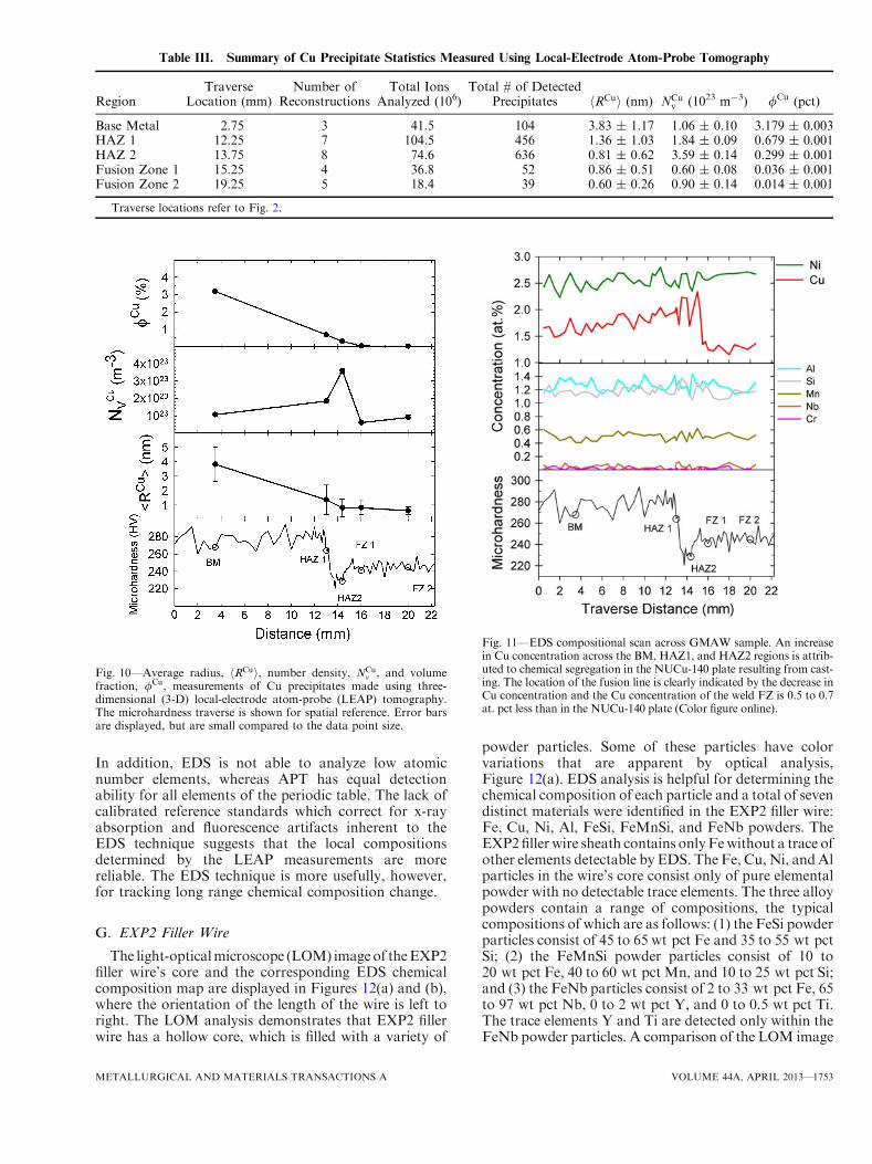
To confirm the local composition measurements fromthe LEAP tomographic analysis, an EDS compositionaltraverse is utilized and the results are displayed inFigure 11. EDS analysis is not able to detect or measurelow concentration elements or elements with atomicnumbers Z< 6. In the GMAW sample, the EDS
analysis was able to measure concentrations for Fe,Cu, Ni, Al, Mn, Si, Nb, and Cr. The concentrations ofeach element are approximately uniform across theNUCu-140 plate and the HAZ regions, with theexception of Cu which is found to increase in concen-tration across the HAZ, with the highest concentrationmeasured in the HAZ adjacent to the fusion line. Thedifference in Cu concentration is approximately 0.9 at.pct between the BM and HAZ edge, just adjacent to thefusion line. Between 15.25 and 15.50 mm on thetraverse, the Cu concentration decreases 0.7 at. pct,and then stays approximately constant through the FZ.The decrease in concentration corresponds to thelocation of the fusion line determined by both micro-hardness and metallographic analyses. The EDS resultsagree with the LEAP tomographic measurements, whichdemonstrate that the FZ contains approximately 0.5 at.pct less Cu than the BM, HAZ1, and HAZ2 regions.The EDS measurements do not exhibit significantchemical segregation in the weld FZ at the mm lengthscale, although there may be micro-segregation on a lmlength scale, which is undetected by EDS analysis.Excellent agreement between EDS and LEAP tomogra-phy is found for the difference in compositions betweenthe BM, HAZ, and FZ regions, even though thesampled volume is smaller for APT than EDS. Thereis, however, disagreement between the absolute compo-sitions of the regions when measured by LEAP tomog-raphy and EDS. The EDS compositional measurementsare based on factory calibrations and are most likelypoorly suited for specific compositional determinations.
Fig. 8—Three-dimensional (3-D) local-electrode atom-probe (LEAP)tomographic reconstructions of samples taken from the Fusion Zone1 (FZ1) region of the weld traverse. Cu precipitates are highlightedusing 5 at. pct Cu (red) isoconcentration surfaces. Fe atoms (blue)are displayed to highlight the reconstructed volumes. No other pha-ses are detected and other elements are omitted for visual clarity.Each reconstruction contains (a) 20.0 million, (b) 7.8 million,(c) 7.3 million, and (d) 1.8 million total ions (Color figure online).
Fig. 9—Three-dimensional (3-D) local-electrode atom-probe (LEAP)tomographic reconstructions of samples taken from the fusion zone2 (FZ2) region of the weld traverse. Cu precipitates are highlightedusing 4 at. pct Cu (red) isoconcentration surfaces. Fe atoms (blue)are displayed to highlight the reconstructed volumes. No other pha-ses are detected and all other elements are omitted for visual clarity.Each 3-D reconstruction contains (a) 7.9 million, (b) 1.9 million,(c) 5.5 million, (d) 1.4 million, and (e) 1.6 million total ions(Color figure online).
1752—VOLUME 44A, APRIL 2013 METALLURGICAL AND MATERIALS TRANSACTIONS A
In addition, EDS is not able to analyze low atomicnumber elements, whereas APT has equal detectionability for all elements of the periodic table. The lack ofcalibrated reference standards which correct for x-rayabsorption and fluorescence artifacts inherent to theEDS technique suggests that the local compositionsdetermined by the LEAP measurements are morereliable. The EDS technique is more usefully, however,for tracking long range chemical composition change.
G. EXP2 Filler Wire
The light-opticalmicroscope (LOM) imageof theEXP2filler wire’s core and the corresponding EDS chemicalcomposition map are displayed in Figures 12(a) and (b),where the orientation of the length of the wire is left toright. The LOM analysis demonstrates that EXP2 fillerwire has a hollow core, which is filled with a variety of
powder particles. Some of these particles have colorvariations that are apparent by optical analysis,Figure 12(a). EDS analysis is helpful for determining thechemical composition of each particle and a total of sevendistinct materials were identified in the EXP2 filler wire:Fe, Cu, Ni, Al, FeSi, FeMnSi, and FeNb powders. TheEXP2filler wire sheath contains onlyFewithout a trace ofother elements detectable by EDS. The Fe, Cu, Ni, andAlparticles in the wire’s core consist only of pure elementalpowder with no detectable trace elements. The three alloypowders contain a range of compositions, the typicalcompositions of which are as follows: (1) the FeSi powderparticles consist of 45 to 65 wt pct Fe and 35 to 55 wt pctSi; (2) the FeMnSi powder particles consist of 10 to20 wt pct Fe, 40 to 60 wt pct Mn, and 10 to 25 wt pct Si;and (3) the FeNb particles consist of 2 to 33 wt pct Fe, 65to 97 wt pct Nb, 0 to 2 wt pct Y, and 0 to 0.5 wt pct Ti.The trace elements Y and Ti are detected only within theFeNb powder particles. A comparison of the LOM image
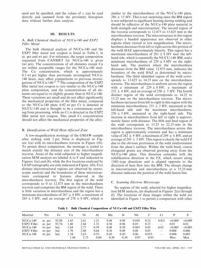
Table III. Summary of Cu Precipitate Statistics Measured Using Local-Electrode Atom-Probe Tomography
Fig. 10—Average radius, hRCui, number density, NCuv , and volume
fraction, /Cu, measurements of Cu precipitates made using three-dimensional (3-D) local-electrode atom-probe (LEAP) tomography.The microhardness traverse is shown for spatial reference. Error barsare displayed, but are small compared to the data point size.
Fig. 11—EDS compositional scan across GMAW sample. An increasein Cu concentration across the BM, HAZ1, and HAZ2 regions is attrib-uted to chemical segregation in the NUCu-140 plate resulting from cast-ing. The location of the fusion line is clearly indicated by the decrease inCu concentration and the Cu concentration of the weld FZ is 0.5 to 0.7at. pct less than in the NUCu-140 plate (Color figure online).
METALLURGICAL AND MATERIALS TRANSACTIONS A VOLUME 44A, APRIL 2013—1753
with the EDS elemental map, Figure 12(b), permits astraightforward identification. In the LOM image, the Fesheath andFeparticles are light gray in color andcomprisethemajority of the imaged area. Cu exists as both particlesand as a film and has a dark reddish-orange color in theLOM image. The Ni particles are a lighter shade of graythan the Fe material in the LOM image, have spheroidalmorphologies, and someappear tobe crackedandbroken.The FeSi and FeSiMn particles are each similarly coloredand are both slightly darker than the Fe sheath, LOMimage; the FeSi particles are multi-sided polygonal par-ticles; and the FeMnSi phase is a thin elongated film. TheAl material is a bright white, LOM image, and is also anelongated film. The FeNb particles are difficult to observeusing LOM due to their small size; however, the EDSanalysis demonstrates that they consist of small spheroidalparticles. This analysis demonstrates that the core of theEXP2filler wire is inhomogeneous anda poor distributionof alloy particles within the Fe sheath may cause compo-sitional fluctuations in the deposited weld. This mayexplain the discrepancy between the bulk compositionmeasured on the EXP2 filler metal test coupon and thechemical composition of the GMAW cross section mea-sured by EDS and LEAP tomography, Table II andFigure 11.
H. Carbon-Rich Films Detected in Heat-Affected Zone
Two of the reconstructions taken from HAZ1,Figures 5(b) and (c), contain carbon-rich films. Increased
magnification images of the two specific reconstructionsare displayed in Figures 13(a) and (b). In Figure 13(a), acarbon-rich film is observed, which traverses the entireLEAP tomographic reconstruction. For purposes of thisanalysis, the two sides of the film are identified as upper(U)-side and lower (L)-side, based on the orientationindicated in Figure 13(a). A NbC precipitate is detectedwholly within the carbon-rich film and a second NbC isdetected immediately adjacent to the U-side ferrite/carbon interface of the film, but wholly contained withinthe ferrite matrix. Cu precipitates are located on both U-and L-sides of the carbon-rich film, both at the ferrite/carbon interfaces and within the ferrite. Three large Cuprecipitates are detected on the U-side of the carbon-richfilm, wholly within the ferrite matrix, and have anellipsoidal morphology. More than 100 smaller, spheroi-dal Cuprecipitates are detected in the ferritematrix on theL-side of the carbon-rich film; a large number are locatedjust adjacent to the L-side ferrite/carbon interface. Thereare no Cu precipitates detected within the carbon-richfilm. The U-side ferrite/carbon interface is not flat, butconsists of several step-like features. Contrastingly, theL-side ferrite/carbon interface is nearly planar and hasonly a slight curvature. The reason for the difference inprofile between the L-side and U-side is not known. Theconcentration profiles of theU-side andL-side Fe/carboninterfaces are determined using proximity histogramsbased on 1.0 at. pct C isoconcentration surfaces and aredisplayed in Figures 14(a) and (b). Prior to the analysis,Cu and NbC precipitates are ‘‘removed’’ from the 3-D
Fig. 12—Metallographic and EDS chemical analysis of the EXP2 filler wire core. The axis of the wire corresponds to right to left. (a) The colorlight-optical microscopy (LOM) image identifies individual core precipitates based on size, shape, and color and (b) the corresponding energydispersive X-ray spectroscopy (EDS) chemical map identifies the particles by composition. The colors in the legend correspond to the EDS maponly. A total of seven unique materials are identified within the filler wire, consisting of Fe, Ni, Al, and Cu metals and FeSi, FeSiMn, and FeNballoy powders (Color figure online).
1754—VOLUME 44A, APRIL 2013 METALLURGICAL AND MATERIALS TRANSACTIONS A
reconstruction using 6.0 and 1.5 at. pct isoconcentrationsurfaces, respectively. After generating the profile, theinterface position is assumed to be the inflection point ofthe C profile and the distances shown in each profile arethen based on that interface position. Figure 14(a) dis-plays the concentration profilesmeasured from theU-sideFe/carbon interface; Ni, Al, Si, and Nb are segregated atthe interface, while a large depletion of Fe and a slight
depletion of H and Mn are observed. The concentrationprofile of the L-side Fe/carbon interface is displayed inFigure 14(b). The L-side interface does not exhibit thesame segregation behavior as the U-side interface; Ni, Al,and Si are only slightly segregated. Surprisingly, a largeenrichment of Mn is measured approximately 3 nm fromthe L-side Fe/carbon interface and is wholly containedwithin the carbon film. The composition of the carbon
Fig. 13—Three-dimensional (3-D) local-electrode atom-probe (LEAP) tomographic reconstructions of carbon-rich phases detected in the HAZ1region employing LEAP tomography. Cu precipitates are highlighted using 4 at. pct isoconcentration surfaces (red), NbC precipitates by 7 at.pct Nb isoconcentration surfaces (brown), and C films by 10 at. pct C isoconcentration surfaces (black). The carbon-rich phase is observed as(a) a film in one reconstruction and (b) as separate plate-shaped precipitates in a second reconstruction. Cu precipitates are detected on theFe/carbon interfaces and within the ferrite matrix of both reconstructions. In (a), the upper (U)- and lower (L)-sides of the carbon-rich film arelabeled for clarity (Color figure online).
Fig. 14—Proximity histograms measured from the (a) upper side (U) and (B) lower side (L) of the Fe/carbon interfaces from the HAZ1 recon-struction displayed in Fig. 13(a). Prior to the analysis, Cu and NbC precipitates are identified and ‘‘removed’’ using 6 at. pct Cu and 1.5 at. pctNb isoconcentration surfaces, respectively. Ni, Si, Al, and Cu are strongly segregated at the U-side interface and only weakly segregated at theL-side interface. Mn was enriched near the L-side interface, approximately 3 nm within the carbon-rich film. The metal/carbon ratio of thisphase is approximately 6:1 (Color figure online).
METALLURGICAL AND MATERIALS TRANSACTIONS A VOLUME 44A, APRIL 2013—1755
film is determined by averaging the plateau regions ofeach histogram concentration profile several nanometerswithin the carbon-rich film. The resulting compositionsdiffer slightly depending onwhich interface is utilized, andthe carbon-rich film composition is 81.41Fe-14.77C-0.07Cu-1.37Ni-0.05Al-1.00Mn-0.08Si-0.05Nb-0.03Cr-0.85H at. pct when measured from the U-side interfaceand 80.07Fe-15.11C-0.11Cu-1.53Ni-0.06Al-1.60Mn-0.09Si-0.05Nb-0.04Cr-0.99H at. pct whenmeasured fromthe L-side interface. Both concentration measurementsare similar for all elements except Mn, which is signif-icantly increased at the L-side interface. The compositionof the Fe matrix can be similarly determined, and is92.67Fe-0.66Cu-2.95Ni-0.80Al-0.35Mn-1.15Si-0.10Nb-0.35C-0.01Cr-0.70H at. pct measured from the U-sideferrite/carbon interface and 90.74Fe-0.80Cu-3.57Ni-0.86Al-0.43Mn-1.10Si-0.13Nb-0.70C-0.02Cr-1.24H at. pctmeasured from the L-side ferrite/carbon interface. The Fematrix on the L-side contains increased concentrations ofCu, Ni, Al, Mn, Nb, C, Cr, and H and a decreasedconcentration of Fe and Si relative to the U-side. Thesecond reconstruction from theHAZ1 region is displayedin Figure 13(b). In contrast with the Figure 13(a), thereconstruction contains two plate-shaped carbon-richphases instead of a carbon-rich film. The sides of eachplate are approximately parallel and step-like features arenot observed. Portions of the plate edges are also observedin the reconstructed volume. Spheroidal Cu precipitatesare observed at the ferrite/carbon interfaces in addition tosmall radii spheroidal Cu precipitates detected in thematrix. The concentration profiles of the carbon-richplate Fe/carbon interfaces are nearly identical to theprofiles of the L-side interface displayed in Fig-ure 14(b) and are omitted for brevity.
IV. DISCUSSION
A. Bulk Chemical Compositions Across Weld
The location of the fusion line is at 15.25 mm in thetraverse distance, Figure 1(b), determined by micro-hardness, SEM metallography, and EDS analysis. Thisindicates that concentrations measured at positions<15.25 mm in the hardness traverse represent theoriginal NUCu-140 plate concentrations, which arenot believed to be inter-mixed with weld metal orsignificantly affected by elements diffusing across thefusion line. Concentrations measured at positions>15.25 mm represent a mixture of NUCu-140 platematerial and EXP2 filler metal. The fluctuations inNUCu-140 plate concentrations measured by both EDSand LEAP tomography are likely the result of chemicalsegregation, which originated in the NUCu-140 plateduring ingot casting.[13] The combination of homogeni-zation and hot rolling applied to the ingots reduces boththe magnitude and wavelength of the concentrationfluctuations, but complete homogenization is difficultand impractical. The concentration fluctuations mea-sured in the FZ by EDS and LEAP tomography areattributed to inter-dendritic segregation, which occurs inthe FZ during solidification. The rapid solidification rateof the FZ results, however, in a finer inter-dendritic
spacing and concentration wavelengths of a reducedlength scale than in the NUCu-140 plate. Of greaterinterest is the concentration mismatch between theNUCu plate material and the weld FZ with respect toCu. Both LEAP tomographic and EDS chemical anal-yses demonstrate that the Cu concentration in the weldFZ is approximately 0.40 to 0.50 at. pct less than in theNUCu-140 plate. The Cu concentration in the FZ isreduced to the extent that minimal precipitation occursduring cooling, even though precipitation is measured inthe HAZ2 region immediately adjacent to the FZ. Thenucleation kinetics of Cu precipitates in the weld FZ areaffected by concentration differences since the drivingforce for nucleation depends on Cu super-saturation inthe Fe matrix. Even if precipitation of Cu was possiblein the FZ during the rapid cooling of the weld,calculations predict a 16 pct decrease in the peak strengthattainable when the Cu concentration is reduced from 1.4to 1.0 at. pct.[61] The most obvious reason for the lowerCu concentration of the weld is a mismatched fillercomposition. In a welding study of HSLA-100 steel, afiller metal was utilized that contained less Cu than theBMin aGMAW,and the resultingweldFZ contained lessCu than the BM due to dilution.[62] This conclusion,however, is in direct contradiction with the bulk compo-sition measured on the EXP2 filler metal test coupon,Table I, which indicates that the EXP2 fillermetal depositshould match the NUCu-140 plate composition. Assum-ing that each measured concentration in this research isaccurate, then the only possible explanation is that theEXP2 filler metal is not deposited with a uniformcomposition. As demonstrated in Figure 12, the EXP2filler wire core is comprised of many different materials,which do not necessarily have a uniform distribution. Forexample, only one Cu powder particle and more than tenNi powder particles are observed, Figure 12, even thoughthe target Ni concentration in NUCu-140 is approxi-mately twice the Cu content. We hypothesize that thealloy powders in the EXP2 filler wire are not uniformlydistributed, resulting in inconsistent deposition, leadingto conflicting compositional measurements. Furtheranalyses of the EXP2 filler wire, EXP2 filler metal testcoupon, or additional GMAW samples may confirm thishypothesis.
B. Loss of Strength in the Heat-Affected Zone
In many steels such as the HY alloys, which containsignificant C levels, the HAZ is increased in strengthrelative to the BM and FZ due to the formation ofuntempered martensite, which is often brittle and delete-rious due to the resulting mechanical properties. In theNUCu-140 GMAW, the HAZ is softened due to dissolu-tion of the Cu precipitates, which is also a problem for theweld strength. Tensile tests have been recently conductedonNUCu-140 welds, which show plastic deformation andeventual failure concentrated in the softened HAZ.[53]
Therefore, the goal of future research is to improve thestrengthof theHAZ tomatch theBMandFZregions. TheLEAP tomographic analyses show that the HAZ hashRCui and/Cu values less than theBMregion, whileNCu
V isslightly increased, and these Cu precipitate measurements
1756—VOLUME 44A, APRIL 2013 METALLURGICAL AND MATERIALS TRANSACTIONS A
should correspond to an under-aged condition in a non-welded sample. Post-weld heating could be used, there-fore, to increase hRCui and /Cu and decrease NCu
V toimprove the strength of the HAZ, assuming the treatmentdoes not weaken the BM. Coarsening studies performedon NUCu-140 demonstrate that appreciable strength isnot lost until 16 hours of aging, while peak strength isreached in less than 1 hour of aging at 723 K (500 �C).[2]Some coarsening of Cu precipitates is inevitable, but thelong times required for strength reduction at 723 K(500 �C) suggest that restrengthening of the HAZ ispossible, while minimizing the loss of strength in the BM.Post-weld heating would, however, significantly increasethe fabrication cost and complexity of large structures. Analternativemethod to improve strength is to use additionalweld passes to reheat the HAZ and FZ. Recently, thismulti-pass welding approach has been successfully dem-onstratedusing simulatedwelds, and strengthwas restoredwithin the weld FZ of a precipitation-strengthened alloycontaining both Cu andM2C carbide precipitates.[63] TheNUCu-140 composition in this study does not containM2C carbides, but an increase in strength frommulti-passwelding should also be possible.
C. Carbon-Rich Films Detectedin the Heat-Affected Zone
The carbon-rich films detected in the HAZ1 region arecomplex in both chemical composition and morphology.To conclusively identify a phase, both the crystal struc-ture and composition are required, and unfortunatelyAPT analysis is unable to determine crystal structure.Based on the composition and morphology, however, wecan attempt to compare these results to other experimentswhich did determine crystal structure. The chemicalcomposition and interfacial concentration profiles ofboth the carbon-rich film, Figure 13(a), and carbon-richplates, Figure 13(b), are nearly identical and we concludethat both represent the same phase with two differentmorphologies. The simplest classification of the carbon-rich phase is Fe3C (cementite), which ideally has a Cconcentration of 25 at. pct, although prior investigationsby APT analysis demonstrate that the measured Cconcentration is typically less. The C concentration inthe unknown phase in the HAZ1 region has a metal-to-carbon ratio ranging from5.5 to 6. If this structure is Fe3C(cementite), then the C concentration would be extremelysmall. Another possible classification of the C-rich phaseis retained austenite. However, due to the large Cconcentration in the film, a classification as a carbide ismore probable. The measured stoichiometry of theunknown phase suggests that a M6C stoichiometriccarbide is more appropriate. Such carbides, designatedg-carbides, exist as equilibrium phases in certain steels,which contain significant concentrations of Mo, W, andCo, and have a globular morphology.[64] Neither theNUCu-140 plate nor the EXP2 filler metal compositionscontain Mo, W, or Co, and the morphology of theunknown phase is obviously not globular, which elimi-nates the possibility that the unknown carbon-rich phaseis the g-carbide. It is possible, however, that the unknownphase represents a non-equilibrium metastable carbon
structure. In prior research, metastable carbides whichformed near room temperature in quenched martensitewere analyzed by APT and the measured C concentrationwas similar to that in this investigation. The authorssuggested the possibility of a striated carbide structurecomposed of C-rich and C-poor regions.[65] The literatureindicates two candidate metastable carbide structures,both of which form during the early stages of tempering inhigh-C martensitic steels. The first structure, identifiedusing APT analysis, has a crystal structure correspondingto Fe16C2 and has a C concentration in the range 10 to 15at. pct.[66,67] The metal-C ratio of such a structure wouldbe 8:1, which is smaller than that measured for theunknown phase. The second possible metastable carbide,identified using TEM diffraction and Mossbauer spec-troscopy studies, has a carbon-multiplet structure. Themultiplet structure contains alternatingC-rich andC-pooratomic planes and the overall structure has a C concen-tration of 14.3 at. pct, corresponding precisely to an Fe6Cstoichiometry, and 6:1 metal-to-C ratio.[68] Additionally,this second carbide structure has been observed with aplate-like morphology, which is consistent with ourobservations of the unknown phase. While absolutestructural classification is not possible based on this data,we hypothesize that this carbon-multiplet structure wasformed in the HAZ1 region under non-equilibriumconditions resulting from the weld thermal cycle.
V. SUMMARY AND CONCLUSIONS
1. An experimental EXP2 filler wire has been devel-oped and used for gas-metal arc welding (GMAW)of an experimental Cu precipitation-strengthenedalloy, NUCu-140. On an experimental GMAWsample, the locations of the base metal (BM), heat-affected zone (HAZ), and fusion zone (FZ) areidentified using metallography, microhardness mea-surements, energy dispersive spectroscopic (EDS)chemical analysis, and local-electrode atom-probe(LEAP) tomographic analysis. The HAZ is foundto be softened relative to BM due to Cu precipitatedissolution.
2. The radius, volume fraction, and number density ofCu precipitates are measured in five regions of theGMAW using LEAP tomography. Both the radiusand volume fraction decrease significantly from theBM to the HAZ due to dissolution. An increase innumber density from BM to the HAZ is measureddue to nucleation of Cu precipitates during cooling.Minimal precipitate nucleation and growth are mea-sured in the FZ due to a reduced Cu super-satura-tion relative to the HAZ. Multi-pass welding isproposed as a potential scheme for nucleating and/or growing Cu precipitates in the HAZ and FZ toimprove strength. Post-weld heating is also possible,but significantly increases fabrication costs.
3. The interfacial concentration profiles of the dissolv-ing Cu precipitates are measured in the BM andHAZ regions and their interfacial excesses aredetermined. The amount of segregation of Ni, Al,and Mn is reduced in the HAZ compared to the
METALLURGICAL AND MATERIALS TRANSACTIONS A VOLUME 44A, APRIL 2013—1757
BM region due to the increased temperature anddissolution of the precipitates.
4. The compositions of the BM, HAZ, and FZ aremeasured using LEAP tomography and EDS chem-ical analysis. A slight increase in Cu concentration,0.5 at. pct, is measured from the BM to the HAZdue to chemical segregation in the NUCu-140 plateresulting from the casting process. A decrease in Cuconcentration of 0.7 at. pct is measured at thefusion line, and the FZ contains 0.4 to 0.5 at. pctless Cu than the NUCu-140 plate. The mismatch inCu concentration is attributed to a non-uniformcomposition in the weld filler wire.
5. An unknown carbon-rich phase, not previouslyobserved by LEAP analysis, is identified in theHAZ of the GMAW sample by LEAP tomography.The unknown phase is detected as both a thin filmand as plate-shaped precipitates and it contains 14.0to 15.0 at. pct C. The interfacial concentration pro-files are determined. Comparing the compositionand morphology of the unknown phase to the ex-tant literature suggests that an Fe6C carbon-multi-plet metastable carbide structure may be present.
ACKNOWLEDGMENTS
This research was funded by the Office of NavalResearch under grants N00014-09-1-0361 and N00014-07-1-0331, Dr. W. W. Mullins, grant monitor. LEAPtomographic measurements were performed at theNorthwestern University Center for Atom-ProbeTomography (NUCAPT). The LEAP tomography sys-tem was purchased with funding from NSF-MRI grantDMR-0420532, with initial funding from ONR-DURIPgrant N00014-0400798, and with funding for upgradesfrom N00014-0610539 and N00014-0910781. Theauthors thank Dr. Dieter Isheim for managingNUCAPT, helpful discussions, and assistance with thisproject. DNS thanks Prof. Emeritus M. E. Fine for gen-erously introducing him to the subject of NU-Cu steels,which he developed over many years at NorthwesternUniversity.
vol. 90 (2), pp. 34–41.2. R.P. Kolli, R.M. Wojes, S. Zaucha, and D.N. Seidman: Int.
J. Mater. Res., 2008, vol. 99 (5), pp. 513–27.3. S. Vaynman, D. Isheim, R.P. Kolli, S.P. Bhat, D.N. Seidman, and
M.E. Fine: Metall. Mater. Trans. A, 2008, vol. 39A, pp. 363–73.4. D. Isheim, R.P. Kolli, M.E. Fine, and D.N. Seidman: Scripta
Mater., 2006, vol. 55 (1), pp. 35–40.5. M.S. Gagliano and M.E. Fine: CALPHAD, 2001, vol. 25 (2),
pp. 207–16.6. M.S. Gagliano and M.E. Fine: CALPHAD, 2004, vol. 35A (8),
pp. 2323–29.7. S. Vaynman, M.E. Fine, and S.P. Bhat: Proceedings from the
Materials Science and Technology 2004 Conference, AIST andTMS, Warrendale, PA, 2004, pp. 417–21.
8. S. Vaynman, M.E. Fine, C. Hahin, N. Biondolillo and C. Crosby:Modern Steel Const., March, 2007.
9. S. Vaynman, M.E. Fine, R.I. Asfahani, D.M. Bormet, and C.Hahin: Microalloyed Steels 2002-Proceedings from the Materials
Solutions Conference 2002, ASM International, Columbus, OH,2002, pp. 43–48.
10. S. Vaynman andM.E. Fine: International Symposium on Steel for Fab-ricated Structures, AIST and ASM, Cincinnati, OH, 1999, pp. 59–66.
11. S. Vaynman, I.J. Uslander, and M.E. Fine: 39th MechanicalWorking and Steel Processing Conference Proceedings, ISS,Indianapolis, IN, 1997, pp. 1183–19.
12. S. Vaynman, M.E. Fine, G. Ghosh, and S.P. Bhat: ‘‘Materials forthe New Millennium’’ Proceedings of the Fourth Materials Engi-neering Conference, ASCE, New York, NY, 1996, pp. 1551–60.
13. G. Krauss: Steels: Processing, Structure, and Performance, ASMInternational, Materials Park, Ohio, 2005, pp. 385–87.
14. ASTM Standard A710-02: Standard Specification for Precipitation-Strengthened Low-Carbon Nickel-Copper-Chromium-Molybdenum-Columbium Alloy Structural Steel Plates, 2007.
15. S. Vaynman, M.E. Fine, S. Lee, and H.D. Espinosa: ScriptaMater., 2006, vol. 55 (4), pp. 351–54.
17. R.P. Kolli and D.N. Seidman: Microsc. Microanal., 2007, vol. 13(4), pp. 272–84.
18. R.P. Kolli, Z. Mao, D.N. Seidman, and D.T. Keane: Appl. Phys.Lett., 2007, vol. 91, p. 241903.
19. R.P. Kolli: Ph.D. Thesis, 2007, Northwestern University.20. E. Hornbogen and R.C. Glenn: Trans. Metall. Soc. AIME, 1960,
vol. 218 (6), pp. 1064–70.21. E. Hornbogen: Acta Metall., 1962, vol. 10, pp. 525–33.22. E. Hornbogen: Acta Metall., 1962, vol. 10, pp. 1187–89.23. G.M. Worrall, J.T. Buswell, C.A. English, M.G. Hetherington,
and G.D.W. Smith: J. Nucl. Mater., 1987, vol. 148 (1), pp. 107–14.24. G.R. Speich and R.A. Oriani: Trans. Metall. Soc. AIME, 1965,
vol. 233 (4), pp. 623–31.25. P.J. Othen, M.L. Jenkins, G.D.W. Smith, and W.J. Phythian:
Philos. Mag. Lett., 1991, vol. 64 (6), pp. 383–91.26. P.J. Othen, M.L. Jenkins, and G.D.W. Smith: Proceedings of the
International Conference on Martensitic Transformations,ICOMAT, California, 1992, pp. 527–32.
27. P.J. Othen, M.L. Jenkins, and G.D.W. Smith: Philos. Mag. A,1994, vol. 70 (1), pp. 1–24.
28. H.R. Habibi-Bajguirani and M.L. Jenkins: Philos. Mag. Lett.,1996, vol. 73 (4), pp. 155–62.
29. S. Lozano-Perez, M.L. Jenkins, and J.M. Titchmarsh: Philos.Mag. Lett., 2006, vol. 86 (6), pp. 367–74.
30. S.R. Goodman, S.S. Brenner, and J.R. Low: Metall. Trans. A,1973, vol. 4A, pp. 2363–69.
31. S.R. Goodman, S.S. Brenner, and J.R. Low: Metall Trans. A,1973, vol. 4A, pp. 2371–78.
32. M.W. Lui and I. Lemay: Metall. Trans. A, 1974, vol. 5A,pp. 1510–11.
33. A. Cerezo, C.R.M. Grovenor, M.G. Hetherington, W. Sha, B.A.Shollock, and G.D.W. Smith: Mater. Charact., 1990, vol. 25 (1),pp. 143–56.
34. K. Osamura, T. Yamamoto, T. Ujihara, H. Okuda, and M.Furusaka: Ann. Phys. (Paris), 1995, vol. 20 (1), pp. 3–10.
35. S.K. Lahiri, D. Chandra, L.H. Schwartz, and M.E. Fine: Trans.Metall. Soc. AIME, 1969, vol. 245 (9), pp. 1865–68.
36. M.A. Sokolov, S. Spooner, G.R. Odette, B.D. Wirth, and G.E.Lucas: 18th International Symposium on Effects of Radiation onMaterials, ASTM, Hyannis, MA, 1999, pp. 333–45.
37. J.T. Buswell, E.A. Little, and R.N. Sinclair: Nucl. Energy Br. Nucl.Energy Soc., 1998, vol. 37 (6), pp. 387–97.
38. F. Maury, N. Lorenzelli, and C.H. Denovion: J. Nucl. Mater.,1991, vol. 183 (3), pp. 217–20.
39. K. Osamura, H. Okuda, K. Asano, M. Furusaka, K. Kishida, andF. Kurosawa: IX International Conference on Small Angle Scat-tering, Saclay, France, 1993, pp. 317–20.
40. K. Osamura, H. Okuda, M. Takashima, K. Asano, and M.Furusaka: Mater. Trans., JIM, 1993, vol. 34 (4), pp. 305–11.
41. K. Osamura, H. Okuda, S. Ochiai, M. Takashima, K. Asano, M.Furusaka, K. Kishida, and F. Kurosawa: ISIJ Int., 1994,vol. 34 (4), pp. 359–65.
42. F. Maury, N. Lorenzelli, C.H. Denovion, and P. Lagarde: ScriptaMetall. Mater., 1991, vol. 25 (8), pp. 1839–44.
43. S. Pizzini, K.J. Roberts, W.J. Phythian, C.A. English, and G.N.Greaves: Philos. Mag. Lett., 1990, vol. 61 (4), pp. 223–29.
1758—VOLUME 44A, APRIL 2013 METALLURGICAL AND MATERIALS TRANSACTIONS A
44. W.J. Phythian, A.J.E. Foreman, C.A. English, J.T. Buswell, M.Hetherington, K. Roberts, and S. Pizzini: Effects of Radiation onMaterials : 15th International Symposium, ASTM, Nashville, TN,1992, pp. 131–50.
45. A.B. Edwards, K.J. Roberts, S. Pizzini, and W.J. Phythian: Philos.Mag. A, 1999, vol. 79 (6), pp. 1295–319.
46. P. Asoka-Kumar, B.D. Wirth, P.A. Sterne, R.H. Howell, andG.R. Odette: Philos. Mag. Lett., 2002, vol. 82 (11), pp. 609–15.
47. K. Verheyen, M. Jardin, and A. Almazouzi: J. Nucl. Mater., 2006,vol. 351 (1–3), pp. 209–15.
48. J.J. Blackstock and G.J. Ackland: Philos. Mag. A, 2001, vol. 81(9), pp. 2127–48.
49. T.Harry andD.J. Bacon:ActaMater., 2002, vol. 50 (1), pp. 195–208.50. T. Harry and D.J. Bacon: Acta Mater., 2002, vol. 50 (1), pp. 209–
22.51. J.Z. Liu, A.V.D. Walle, G. Ghosh, and M. Asta: Phys. Rev. B:
Condens. Matter Mater. Phys., 2005, vol. 72 (14), pp. 1–16.52. E. Kozeschnik: Scripta Mater., 2008, vol. 59 (9), pp. 1018–21.53. J. Farren, A.H. Hunter, D.N. Seidman, C. Robino, E. Kozeschnik,
and J. DuPont: Metall. Mater. Trans. A, 2012, Appeared onlineJuly 4, 2012.
54. B. Leister and J.N. DuPont: Weld. J. (Miami, Fl, U. S.), 2012, inpress.
55. Astm Standard E384-10e1 Standard Test Method for Knoop andVickers Hardness of Materials.
56. D. Isheim, A.H. Hunter, X.J. Zhang, and D.N. Seidman:unpublished research, 2012.
57. O.C. Hellman, J.A. Vandenbroucke, J. Rusing, D. Isheim, andD.N. Seidman: Microsc. Microanal., 2000, vol. 6 (5), pp. 437–44.
58. J.W. Cahn: Interfacial Segregation, American Society for Metals,Chicago, IL, 1977, pp. 3–23.
59. O.C. Hellman and D.N. Seidman: Mater. Sci. Eng., A, 2002,vol. 327 (1), pp. 24–28.
60. H.K.D.H. Bhadeshia and R.W.K. Honeycombe: Steels : Micro-structure and Properties, 3rd, Butterworth-Heinemann, Oxford,U.K., 2006.
61. A. Saha and G.B. Olson: J. Comput-Aided Mater. Des., 2007,vol. 14 (2), pp. 177–200.
62. G. Spanos, D.W. Moon, R.W. Fonda, E.S.K. Menon, and A.G.Fox: Metall. Mater. Trans. A, 2001, vol. 32A, pp. 3043–54.
63. X.H. Yu, J.L. Caron, S.S. Babu, J.C. Lippold, D. Isheim, andD.N. Seidman: Metall. Mater. Trans. A, 2011, vol. 42A, pp. 3669–79.
64. J.R. Davis: Alloying : Understanding the Basics, ASM Interna-tional, Materials Park, OH, 2001, pp. 223–33.
65. C. Zhu, A. Cerezo, and G.D.W Smith: Ultramicroscopy, 2009,vol. 109 (5), pp. 545–52.
66. K.A. Taylor, L. Chang, G.B. Olson, G.D.W. Smith, M. Cohen,and J.B. Vandersande: Metall. Trans. A, 1989, vol. 20A, pp. 2717–37.
67. K.A. Taylor, G.B. Olson, M. Cohen, and J.B. Vandersande:Metall. Trans. A, 1989, vol. 20A, pp. 2749–65.
68. O.N.C. Uwakweh, J.M.R. Genin, and J.F. Silvain: Metall. Trans.A, 1991, vol. 22A, pp. 797–806.
METALLURGICAL AND MATERIALS TRANSACTIONS A VOLUME 44A, APRIL 2013—1759