New York State Division of Mineral Resources Appendix 16 Applicability of NOx RACT Requirements for Natural Gas Production Facilities Draft Supplemental Generic Environmental Impact Statement DEC
Applicability of NOx RACT Requirements for Natural Gas Production Facilities
New York State’s air regulation Part 227-2, Reasonably Available Control Technology (RACT) for Oxides of Nitrogen (NOx), applies to boilers (furnaces) and internal combustion engines at major sources. The requirements of Part 227-2 include emission limits, stack testing, and annual tune-ups, among others. Many facilities whose potential to emit (PTE) air pollutants would make them susceptible to NOx RACT requirements can limit, or “cap”, their emissions using the limits within the New York State Department of Environmental Conservation’s (DEC) Air Emissions Permits applicability thresholds to avoid this regulation. New York State has two different major source thresholds for NOx RACT and permitting. Downstate (in New York City and Nassau, Suffolk, Westchester, Rockland, and Lower Orange Counties) the major source permitting and NOx RACT requirements apply to facilities with a PTE of 25 tons/yr or more of NOx. For the rest of the state (where the majority of natural gas production facilities are anticipated to be located), the threshold is a PTE of 100 tons/yr or more of NOx. If the stationary engines at a natural gas production facility exceed the applicability levels or if the PTE at the facility would classify it as a Major NOx source, the following compliance options are available:
1. Develop a NOx RACT compliance plan and apply for a Title V permit.
2. Limit the facility’s emissions to remain under the NOx RACT applicability levels by applying for one of two New York State Air Emissions permits, depending on how low emissions can be limited.
The permitting options for facilities that wish to limit, or “cap”, their emissions by establishing appropriate permit conditions are described below. New York State’s air regulation Part 201, Permits and Registrations, includes a provision that allows a facility to register if its actual emissions are less than 50% of the applicability thresholds (less than 12.5 tons/yr downstate and less than 50 tons/yr upstate). This permit option is known as “cap by rule” registration. Part 201 also includes a provision that allows a facility to limit its emissions by obtaining a State Facility Permit, if its actual emissions are above the 50% level but below the applicability level (between 12.5 and 25 tons/yr downstate and between 50 and 100 tons/yr upstate). If the facility NOx emissions cannot be capped below the applicablity levels, then the facility should immediately develop a NOx RACT compliance plan. This plan should contain the necessary steps (purchase of equipment and controls, installation of equipment, source testing, submittal of permit application, etc.) and projected completion dates required to bring the facility into compliance. This plan is to be submitted to the appropriate DEC Regional Office as soon as
possible. In this case the facility would also be subject to Title V, and a Title V air permit application must be prepared and submitted.
New York State Division of Mineral Resources
Appendix 17
Applicability of Proposed Revision of 40 CFG Part 63 Subpart ZZZZ (Engine MACT) for
Applicability of Proposed Revision of 40 CFR Part 63 Subpart ZZZZ (Engine MACT) for
Natural Gas Production Facilities
This action proposes to revise 40 CFR Part 63, Subpart ZZZZ, in order to address hazardous air pollutants (HAP) emissions from existing stationary reciprocating internal combustion engines (RICE) located at area sources. A major source of HAP emissions is a stationary source that emits or has the potential to emit any single HAP at a rate of 10 tons or more per year or any combination of HAP at a rate of 25 tons or more per year. An area source of HAP emissions is a source that is not a major source. Available emissions data show that several HAP, which are formed during the combustion process or which are contained within the fuel burned, are emitted from stationary engines. The HAP which have been measured in emission tests conducted on natural gas fired and diesel fired RICE include: 1,1,2,2-tetrachloroethane, 1,3-butadiene, 2,2,4-trimethylpentane, acetaldehyde, acrolein, benzene, chlorobenzene, chloroethane, ethylbenzene, formaldehyde, methanol, methylene chloride, n-hexane, naphthalene, polycyclic aromatic hydrocarbons, polycyclic organic matter, styrene, tetrachloroethane, toluene, and xylene. Metallic HAP from diesel fired stationary RICE that have been measured are: cadmium, chromium, lead, manganese, mercury, nickel, and selenium. Although numerous HAP may be emitted from RICE, only a few account for essentially all of the mass of HAP emissions from stationary RICE. These HAP are: formal- dehyde, acrolein, methanol, and acetaldehyde. EPA is proposing to limit emissions of HAP through emissions standards for formaldehyde for non-emergency four stroke-cycle rich burn (4SRB) engines, and engines less than 50 HP, and through emission standards for carbon monoxide (CO) for all other engines. The applicable emission standards (at 15% oxygen) or management practices for existing RICE located at area sources are as follows:
Subcategory
Emission standards at 15 percent O2, as applicable, or management practice
Except during periods of startup, or malfunction
During periods of startup, or malfunction
Non‐Emergency 4SLB* ≥250HP 9 ppmvd CO or 90% CO reduction 95 ppmvd CO.
Non‐Emergency 4SLB 50‐250HP Change oil and filter every 500 hours; replace spark plugs every 1000 hours; and inspect all hoses and belts every 500 hours and re‐place as necessary.
Change oil and filter every 500 hours; replace spark plugs every 1000 hours; and inspect all hoses and belts every 500 hours and re‐place as necessary.
Non‐Emergency 4SRB** ≥50HP 200 ppbvd formaldehyde or 90% formaldehyde reduction.
2 ppmvd formaldehyde.
Non‐Emergency CI >300HP 4 ppmvd CO or 90% CO reduction 40 ppmvd CO.
Non‐Emergency CI*** 50‐300HP Change oil and filter every 500 hours; inspect air cleaner every 1000 hours; and inspect all hoses and belts every 500 hours and re‐place as necessary.
Change oil and filter every 500 hours; replace spark plugs every 1000 hours; and inspect all hoses and belts every 500 hours and re‐place as necessary.
Non‐Emergency CI <50HP Change oil and filter every 200 hours; replace spark plugs every 500 hours; and inspect all hoses and belts every 500 hours and re‐place as necessary.
Change oil and filter every 200 hours; replace spark plugs every 500 hours; and inspect all hoses and belts every 500 hours and re‐place as necessary.
*4SLB - four stroke-cycle lean burn **4SRB – four stroke-cycle rich burn ***CI – compression ignition Fuel Requirements
In addition to emission standards and management practices, certain stationary CI RICE located at existing area sources are subject to fuel requirements. stationary non-emergency diesel-fueled CI engines greater than 300 HP with a displacement of less than 30 liters per cylinder located at existing area sources must only use diesel fuel meeting the requirements of 40 CFR 80.510(b), which requires that diesel fuel have a maximum sulfur content of 15 ppm and either a minimum cetane index of 40 or a maximum aromatic content of 35 volume percent.
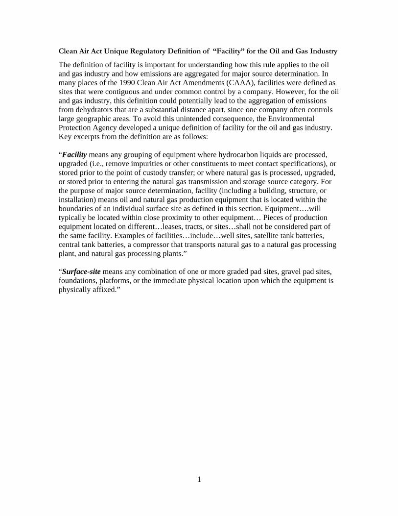
Clean Air Act Unique Regulatory Definition of “Facility” for the Oil and Gas Industry
The definition of facility is important for understanding how this rule applies to the oil and gas industry and how emissions are aggregated for major source determination. In many places of the 1990 Clean Air Act Amendments (CAAA), facilities were defined as sites that were contiguous and under common control by a company. However, for the oil and gas industry, this definition could potentially lead to the aggregation of emissions from dehydrators that are a substantial distance apart, since one company often controls large geographic areas. To avoid this unintended consequence, the Environmental Protection Agency developed a unique definition of facility for the oil and gas industry. Key excerpts from the definition are as follows: “Facility means any grouping of equipment where hydrocarbon liquids are processed, upgraded (i.e., remove impurities or other constituents to meet contact specifications), or stored prior to the point of custody transfer; or where natural gas is processed, upgraded, or stored prior to entering the natural gas transmission and storage source category. For the purpose of major source determination, facility (including a building, structure, or installation) means oil and natural gas production equipment that is located within the boundaries of an individual surface site as defined in this section. Equipment….will typically be located within close proximity to other equipment… Pieces of production equipment located on different…leases, tracts, or sites…shall not be considered part of the same facility. Examples of facilities…include…well sites, satellite tank batteries, central tank batteries, a compressor that transports natural gas to a natural gas processing plant, and natural gas processing plants.” “Surface-site means any combination of one or more graded pad sites, gravel pad sites, foundations, platforms, or the immediate physical location upon which the equipment is physically affixed.”
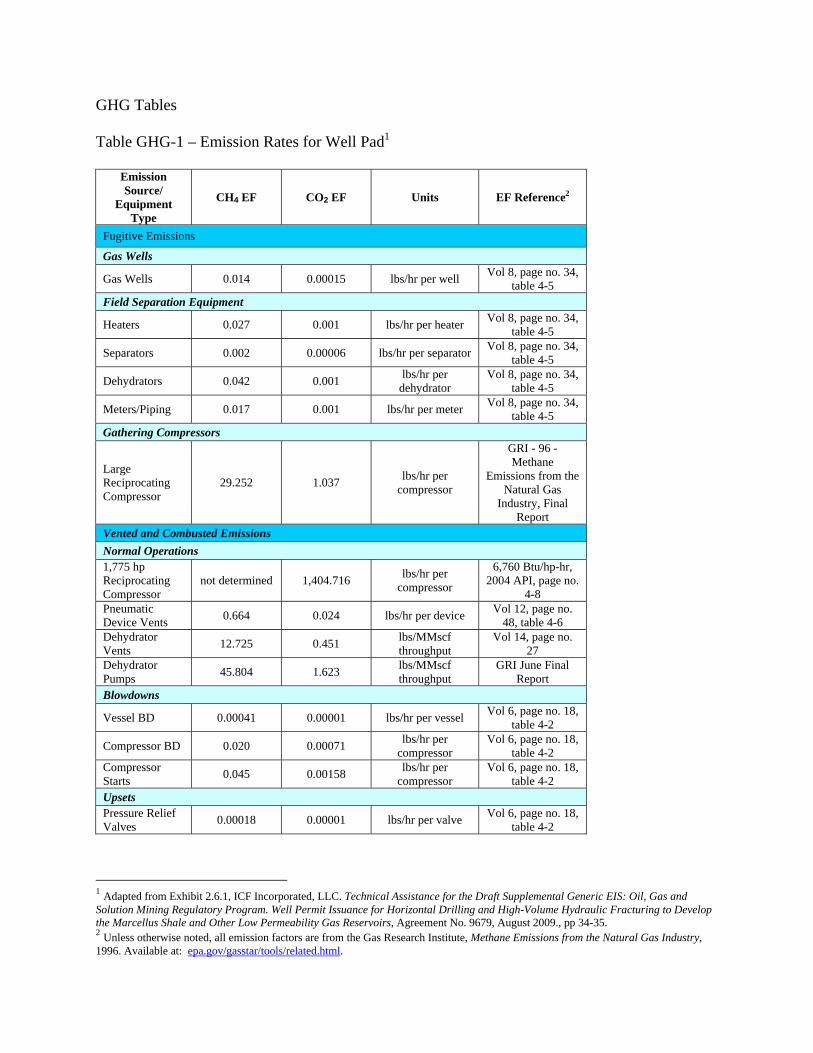
1 Adapted from Exhibit 2.6.1, ICF Incorporated, LLC. Technical Assistance for the Draft Supplemental Generic EIS: Oil, Gas and Solution Mining Regulatory Program. Well Permit Issuance for Horizontal Drilling and High-Volume Hydraulic Fracturing to Develop the Marcellus Shale and Other Low Permeability Gas Reservoirs, Agreement No. 9679, August 2009., pp 34-35. 2 Unless otherwise noted, all emission factors are from the Gas Research Institute, Methane Emissions from the Natural Gas Industry, 1996. Available at: epa.gov/gasstar/tools/related.html.
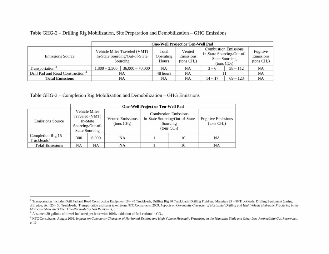
Table GHG-2 – Drilling Rig Mobilization, Site Preparation and Demobilization – GHG Emissions One-Well Project or Ten-Well Pad
Emissions Source Vehicle Miles Traveled (VMT) In-State Sourcing/Out-of-State
Sourcing
Total Operating
Hours
Vented Emissions (tons CH4)
Combustion Emissions In-State Sourcing/Out-of-
State Sourcing (tons CO2)
Fugitive Emissions (tons CH4)
Transportation 3 1,800 – 3,500 36,000 – 70,000 NA NA 3 – 6 58 – 112 NA Drill Pad and Road Construction 4 NA 48 hours NA 11 NA
Total Emissions NA NA NA 14 – 17 69 – 123 NA Table GHG-3 – Completion Rig Mobilization and Demobilization – GHG Emissions One-Well Project or Ten-Well Pad
Completion Rig 15 Truckloads5 300 6,000 NA 1 10 NA
Total Emissions NA NA NA 1 10 NA
3 Transportation includes Drill Pad and Road Construction Equipment 10 – 45 Truckloads, Drilling Rig 30 Truckloads, Drilling Fluid and Materials 25 – 50 Truckloads, Drilling Equipment (casing, drill pipe, etc.) 25 – 50 Truckloads. Transportation estimates taken from NTC Consultants, 2009. Impacts on Community Character of Horizontal Drilling and High Volume Hydraulic Fracturing in the Marcellus Shale and Other Low-Permeability Gas Reservoirs, p. 13. 4 Assumed 20 gallons of diesel fuel used per hour with 100% oxidation of fuel carbon to CO2. 5 NTC Consultants, August 2009. Impacts on Community Character of Horizontal Drilling and High Volume Hydraulic Fracturing in the Marcellus Shale and Other Low-Permeability Gas Reservoirs, p. 13
Table GHG-4 – Well Drilling – GHG Emissions One-Well Project Ten-Well Pad
Emissions Source Total
Operating Hours
Activity Factor
Vented Emissions
(tons CH4)
Combustion Emissions (tons CO2)
Fugitive Emissions
(tons CH4)
Total Operating
Hours
Activity Factor
Vented Emissions
(tons CH4)
Combustion Emissions (tons CO2)
Fugitive Emissions
(tons CH4)
Power Engines6 168 hours 1 NA 94 NA 1680 hours 1 NA 940 NA
Circulating System7 168 hours 1 negligible NA negligible 1680 hours 1 negligible NA negligible
Well Control System8 As needed 1 negligible negligible negligible As
needed 1 negligible negligible negligible
Total Emissions NA NA negligible 94 negligible NA NA negligible 940 negligible
6 Power Engines include rig engines, air compressor engines, mud pump engines and electrical generator engines. Assumed 50 gallons of diesel fuel used per hour with 100% oxidation of fuel carbon to CO2. 7 Circulating system includes mud system piping and valves, mud-gas separator, mud pits or tanks and blooie line for air drilling. 8 Well Control System includes well control piping and valves, BOP, choke manifold and flare line.
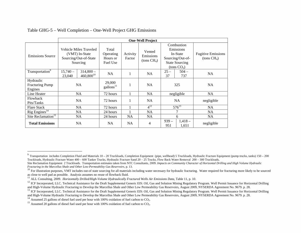
Line Heater NA 72 hours 1 NA negligible NA Flowback Pits/Tanks NA 72 hours 1 NA NA negligible
Flare Stack NA 72 hours 1 412 57613 NA Rig Engines14 NA 24 hours 1 NA 7 NA Site Reclamation15 NA 24 hours NA NA 6 NA
Total Emissions NA NA NA 4 939 – 951
1,418 – 1,651 negligible
9 Transportation includes Completion Fluid and Materials 10 – 20 Truckloads, Completion Equipment (pipe, wellhead) 5 Truckloads, Hydraulic Fracture Equipment (pump trucks, tanks) 150 – 200 Truckloads, Hydraulic Fracture Water 400 – 600 Tanker Trucks, Hydraulic Fracture Sand 20 – 25 Trucks, Flow Back Water Removal 200 – 300 Truckloads, Site Reclamation Equipment 2 Truckloads. Transportation estimates taken from NTC Consultants, 2009. Impacts on Community Character of Horizontal Drilling and High Volume Hydraulic Fracturing in the Marcellus Shale and Other Low-Permeability Gas Reservoirs, p. 13. 10 For illustration purposes, VMT includes out-of state sourcing for all materials including water necessary for hydraulic fracturing. Water required for fracturing more likely to be sourced as close to well pad as possible. Analysis assumes no reuse of flowback fluid. 11 ALL Consulting, 2009. Horizontally Drilled/High-Volume Hydraulically Fractured Wells Air Emissions Data, Table 11, p. 10. 12 ICF Incorporated, LLC. Technical Assistance for the Draft Supplemental Generic EIS: Oil, Gas and Solution Mining Regulatory Program. Well Permit Issuance for Horizontal Drilling and High-Volume Hydraulic Fracturing to Develop the Marcellus Shale and Other Low Permeability Gas Reservoirs, August 2009, NYSERDA Agreement No. 9679. p. 28. 13 ICF Incorporated, LLC. Technical Assistance for the Draft Supplemental Generic EIS: Oil, Gas and Solution Mining Regulatory Program. Well Permit Issuance for Horizontal Drilling and High-Volume Hydraulic Fracturing to Develop the Marcellus Shale and Other Low Permeability Gas Reservoirs, August 2009, NYSERDA Agreement No. 9679. p. 28. 14 Assumed 25 gallons of diesel fuel used per hour with 100% oxidation of fuel carbon to CO2. 15 Assumed 20 gallons of diesel fuel used per hour with 100% oxidation of fuel carbon to CO2.
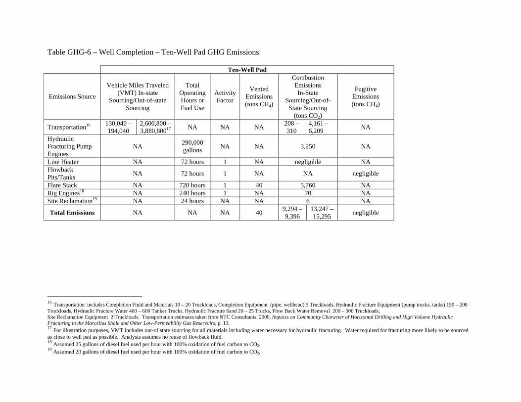
Table GHG-6 – Well Completion – Ten-Well Pad GHG Emissions Ten-Well Pad
Emissions Source
Vehicle Miles Traveled (VMT) In-state
Sourcing/Out-of-state Sourcing
Total Operating Hours or Fuel Use
Activity Factor
Vented Emissions (tons CH4)
Combustion Emissions In-State
Sourcing/Out-of-State Sourcing
(tons CO2)
Fugitive Emissions (tons CH4)
Transportation16 130,040 – 194,040
2,600,800 – 3,880,80017 NA NA NA 208 –
310 4,161 – 6,209 NA
Hydraulic Fracturing Pump Engines
NA 290,000 gallons NA NA 3,250 NA
Line Heater NA 72 hours 1 NA negligible NA Flowback Pits/Tanks NA 72 hours 1 NA NA negligible
Flare Stack NA 720 hours 1 40 5,760 NA Rig Engines18 NA 240 hours 1 NA 70 NA Site Reclamation19 NA 24 hours NA NA 6 NA
Total Emissions NA NA NA 40 9,294 – 9,396
13,247 – 15,295 negligible
16 Transportation includes Completion Fluid and Materials 10 – 20 Truckloads, Completion Equipment (pipe, wellhead) 5 Truckloads, Hydraulic Fracture Equipment (pump trucks, tanks) 150 – 200 Truckloads, Hydraulic Fracture Water 400 – 600 Tanker Trucks, Hydraulic Fracture Sand 20 – 25 Trucks, Flow Back Water Removal 200 – 300 Truckloads, Site Reclamation Equipment 2 Truckloads. Transportation estimates taken from NTC Consultants, 2009. Impacts on Community Character of Horizontal Drilling and High Volume Hydraulic Fracturing in the Marcellus Shale and Other Low-Permeability Gas Reservoirs, p. 13. 17 For illustration purposes, VMT includes out-of state sourcing for all materials including water necessary for hydraulic fracturing. Water required for fracturing more likely to be sourced as close to well pad as possible. Analysis assumes no reuse of flowback fluid. 18 Assumed 25 gallons of diesel fuel used per hour with 100% oxidation of fuel carbon to CO2. 19 Assumed 20 gallons of diesel fuel used per hour with 100% oxidation of fuel carbon to CO2.
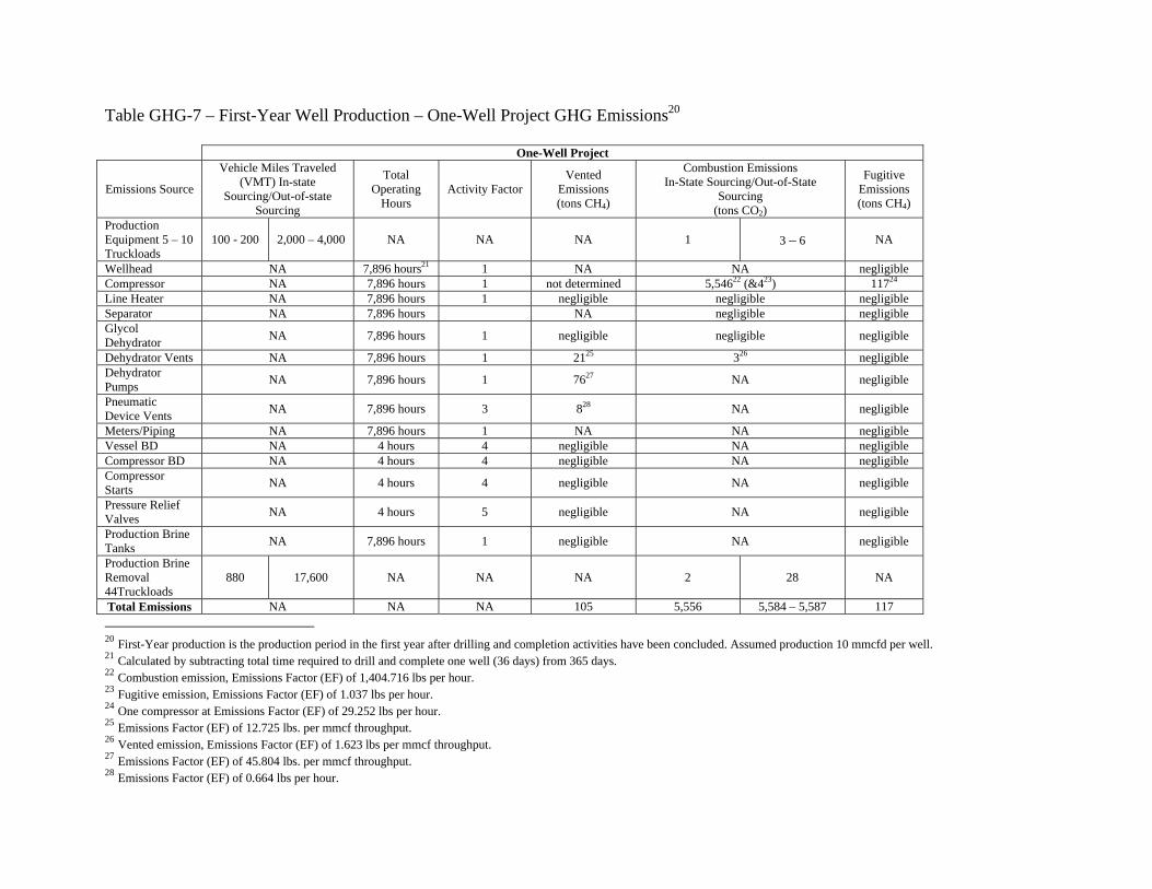
Table GHG-7 – First-Year Well Production – One-Well Project GHG Emissions20 One-Well Project
Wellhead NA 7,896 hours21 1 NA NA negligible Compressor NA 7,896 hours 1 not determined 5,54622 (&423) 11724 Line Heater NA 7,896 hours 1 negligible negligible negligible Separator NA 7,896 hours NA negligible negligible Glycol Dehydrator NA 7,896 hours 1 negligible negligible negligible
Dehydrator Vents NA 7,896 hours 1 2125 326 negligible Dehydrator Pumps NA 7,896 hours 1 7627 NA negligible
Pneumatic Device Vents NA 7,896 hours 3 828 NA negligible
Meters/Piping NA 7,896 hours 1 NA NA negligible Vessel BD NA 4 hours 4 negligible NA negligible Compressor BD NA 4 hours 4 negligible NA negligible Compressor Starts NA 4 hours 4 negligible NA negligible
Pressure Relief Valves NA 4 hours 5 negligible NA negligible
Production Brine Tanks NA 7,896 hours 1 negligible NA negligible
Production Brine Removal 44Truckloads
880 17,600 NA NA NA 2 28 NA
Total Emissions NA NA NA 105 5,556 5,584 – 5,587 117 20 First-Year production is the production period in the first year after drilling and completion activities have been concluded. Assumed production 10 mmcfd per well. 21 Calculated by subtracting total time required to drill and complete one well (36 days) from 365 days. 22 Combustion emission, Emissions Factor (EF) of 1,404.716 lbs per hour. 23 Fugitive emission, Emissions Factor (EF) of 1.037 lbs per hour. 24 One compressor at Emissions Factor (EF) of 29.252 lbs per hour. 25 Emissions Factor (EF) of 12.725 lbs. per mmcf throughput. 26 Vented emission, Emissions Factor (EF) of 1.623 lbs per mmcf throughput. 27 Emissions Factor (EF) of 45.804 lbs. per mmcf throughput. 28 Emissions Factor (EF) of 0.664 lbs per hour.
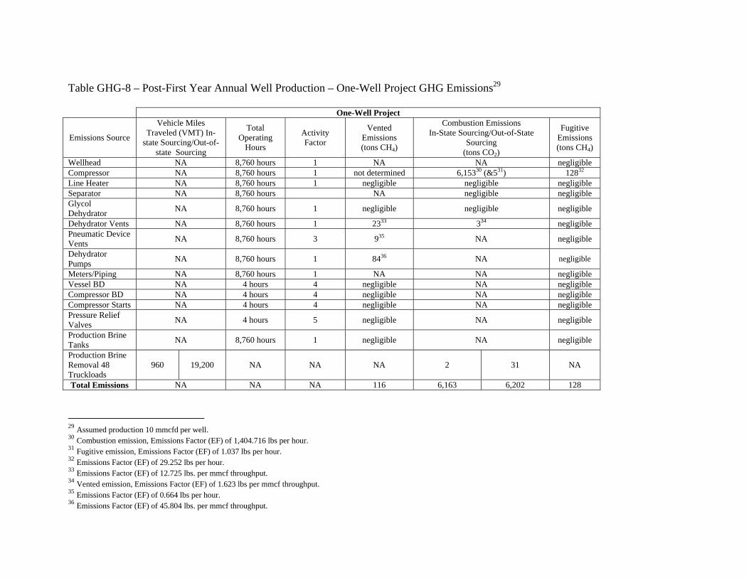
Table GHG-8 – Post-First Year Annual Well Production – One-Well Project GHG Emissions29 One-Well Project
Wellhead NA 8,760 hours 1 NA NA negligible Compressor NA 8,760 hours 1 not determined 6,15330 (&531) 12832 Line Heater NA 8,760 hours 1 negligible negligible negligible Separator NA 8,760 hours NA negligible negligible Glycol Dehydrator NA 8,760 hours 1 negligible negligible negligible
Dehydrator Vents NA 8,760 hours 1 2333 334 negligible Pneumatic Device Vents NA 8,760 hours 3 935 NA negligible
Dehydrator Pumps NA 8,760 hours 1 8436 NA negligible
Meters/Piping NA 8,760 hours 1 NA NA negligible Vessel BD NA 4 hours 4 negligible NA negligible Compressor BD NA 4 hours 4 negligible NA negligible Compressor Starts NA 4 hours 4 negligible NA negligible Pressure Relief Valves NA 4 hours 5 negligible NA negligible
Production Brine Tanks NA 8,760 hours 1 negligible NA negligible
Production Brine Removal 48 Truckloads
960 19,200 NA NA NA 2 31 NA
Total Emissions NA NA NA 116 6,163 6,202 128
29 Assumed production 10 mmcfd per well. 30 Combustion emission, Emissions Factor (EF) of 1,404.716 lbs per hour. 31 Fugitive emission, Emissions Factor (EF) of 1.037 lbs per hour. 32 Emissions Factor (EF) of 29.252 lbs per hour. 33 Emissions Factor (EF) of 12.725 lbs. per mmcf throughput. 34 Vented emission, Emissions Factor (EF) of 1.623 lbs per mmcf throughput. 35 Emissions Factor (EF) of 0.664 lbs per hour. 36 Emissions Factor (EF) of 45.804 lbs. per mmcf throughput.
Table GHG-9 – First-Year Well Production – Ten-Well Pad GHG Emissions37 Ten-Well Pad
Emissions Source
Vehicle Miles Traveled (VMT) In-state
Sourcing/Out-of-state Sourcing
Total Operating Hours Activity Factor Vented Emissions
Wellhead NA 120 hours38 10 NA NA Compressor NA 120 hours 3 not determined 25339 (&140) 641 Line Heater NA 120 hours 3 negligible negligible negligible Separator NA 120 hours 3 NA negligible negligible Glycol Dehydrator NA 120 hours 2 negligible negligible negligible Dehydrator Vents NA 120 hours 142 443 144 negligible Dehydrator Pumps NA 120 hours 145 946 NA negligible Pneumatic Device Vents NA 120 hours 6 147 NA negligible
Meters/Piping NA 120 hours 1 NA NA negligible Vessel BD NA 2 hours 9 negligible NA negligible Compressor BD NA 2 hours 4 negligible NA negligible Compressor Starts NA 2 hours 4 negligible NA negligible Pressure Relief Valves NA 2 hours 19 negligible NA negligible
Production Brine Tanks NA 120 hours 2 negligible NA negligible
Production Brine Removal 40 Truckloads
NA NA NA NA NA NA
Total Emissions NA NA NA 14 256 258 – 261 6
37 First-Year production is the production period in the first year after drilling and completion activities have been concluded. Assumed production 10 mmcfd per well. 38 Calculated by subtracting total time required to drill and complete ten wells (360 days) from 365 days. 39 Combustion emission, Emissions Factor (EF) of 1,404.716 lbs per hour. 40 Fugitive emission, Emissions Factor (EF) of 1.037 lbs per hour. 41 Emissions Factor (EF) of 29.252 lbs per hour. 42 Emissions Factor (EF) based on throughput, not number of units. 43 Emissions Factor (EF) of 12.725 lbs. per mmcf throughput. 44 Vented emission, Emissions Factor (EF) of 1.623 lbs per mmcf throughput. 45 Emissions Factor (EF) based on throughput, not number of units. 46 Emissions Factor (EF) of 45.804 lbs. per mmcf throughput. 47 Emissions Factor (EF) of 0.664 lbs per hour.
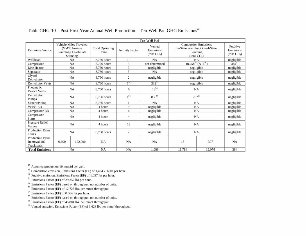
Table GHG-10 – Post-First Year Annual Well Production – Ten-Well Pad GHG Emissions48 Ten-Well Pad
Wellhead NA 8,760 hours 10 NA NA negligible Compressor NA 8,760 hours 3 not determined 18,45849 (&1450) 38451 Line Heater NA 8,760 hours 3 negligible negligible negligible Separator NA 8,760 hours 3 NA negligible negligible Glycol Dehydrator NA 8,760 hours 2 negligible negligible negligible
Dehydrator Vents NA 8,760 hours 152 23253 negligible negligible Pneumatic Device Vents NA 8,760 hours 6 1854 NA negligible
Dehydrator Pumps NA 8,760 hours 155 83656 29757 negligible
Meters/Piping NA 8,760 hours 1 NA NA negligible Vessel BD NA 4 hours 9 negligible NA negligible Compressor BD NA 4 hours 4 negligible NA negligible Compressor Starts NA 4 hours 4 negligible NA negligible
Pressure Relief Valves NA 4 hours 19 negligible NA negligible
Production Brine Tanks NA 8,760 hours 2 negligible NA negligible
Production Brine Removal 480 Truckloads
9,600 192,000 NA NA NA 15 307 NA
Total Emissions NA NA NA 1,086 18,784 19,076 384 48 Assumed production 10 mmcfd per well. 49 Combustion emission, Emissions Factor (EF) of 1,404.716 lbs per hour. 50 Fugitive emission, Emissions Factor (EF) of 1.037 lbs per hour. 51 Emissions Factor (EF) of 29.252 lbs per hour. 52 Emissions Factor (EF) based on throughput, not number of units. 53 Emissions Factor (EF) of 12.725 lbs. per mmcf throughput. 54 Emissions Factor (EF) of 0.664 lbs per hour. 55 Emissions Factor (EF) based on throughput, not number of units. 56 Emissions Factor (EF) of 45.804 lbs. per mmcf throughput. 57 Vented emission, Emissions Factor (EF) of 1.623 lbs per mmcf throughput.
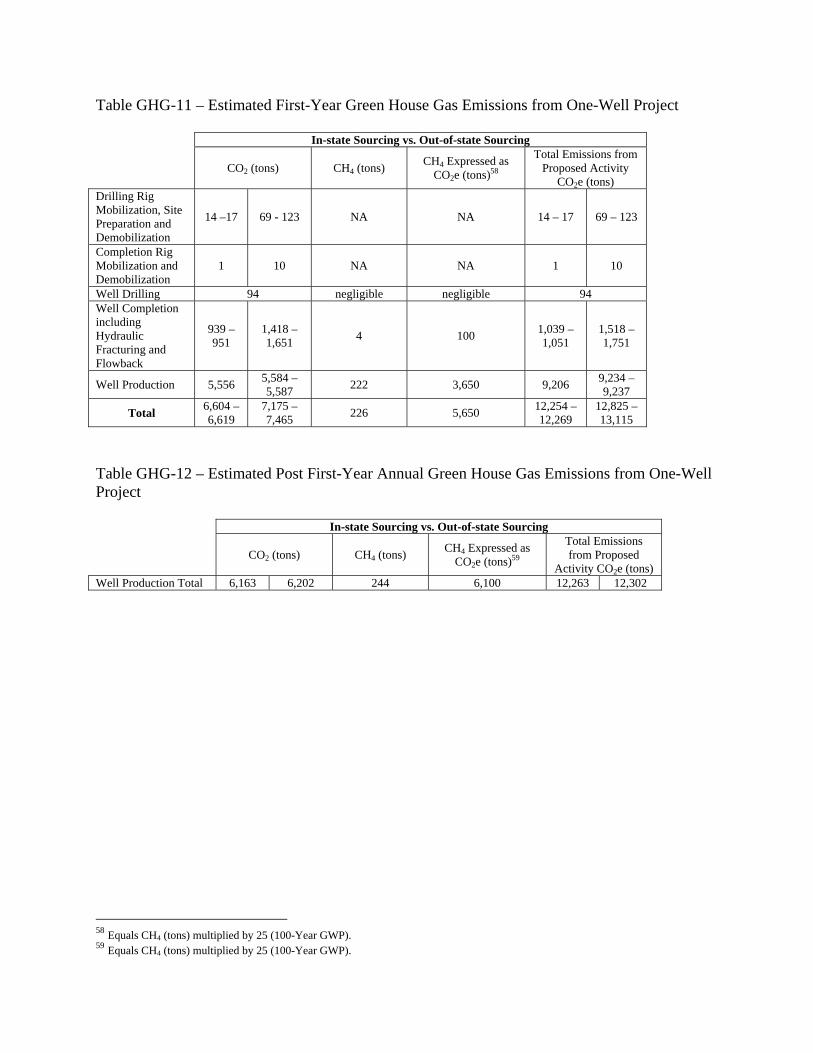
Table GHG-11 – Estimated First-Year Green House Gas Emissions from One-Well Project In-state Sourcing vs. Out-of-state Sourcing
CO2 (tons) CH4 (tons) CH4 Expressed as CO2e (tons)58
Total Emissions from Proposed Activity
CO2e (tons) Drilling Rig Mobilization, Site Preparation and Demobilization
14 –17 69 - 123 NA NA 14 – 17 69 – 123
Completion Rig Mobilization and Demobilization
1 10 NA NA 1 10
Well Drilling 94 negligible negligible 94 Well Completion including Hydraulic Fracturing and Flowback
939 – 951
1,418 – 1,651 4 100 1,039 –
1,051 1,518 – 1,751
Well Production 5,556 5,584 – 5,587 222 3,650 9,206 9,234 –
9,237
Total 6,604 – 6,619
7,175 – 7,465 226 5,650 12,254 –
12,269 12,825 – 13,115
Table GHG-12 – Estimated Post First-Year Annual Green House Gas Emissions from One-Well Project In-state Sourcing vs. Out-of-state Sourcing
CO2 (tons) CH4 (tons) CH4 Expressed as CO2e (tons)59
Total Emissions from Proposed
Activity CO2e (tons) Well Production Total 6,163 6,202 244 6,100 12,263 12,302
58 Equals CH4 (tons) multiplied by 25 (100-Year GWP). 59 Equals CH4 (tons) multiplied by 25 (100-Year GWP).
Table GHG-13 – Estimated First-Year Green House Gas Emissions from Ten-Well Pad In-state Sourcing vs. Out-of-state Sourcing
CO2 (tons) CH4 (tons) CH4 Expressed as CO2e (tons)60
Total Emissions from Proposed Activity CO2e
(tons) Drilling Rig Mobilization, Site Preparation and Demobilization
14 – 17 69 – 123 NA NA 14 – 17 69 – 123
Completion Rig Mobilization and Demobilization
1 10 NA NA 1 10
Well Drilling 940 negligible negligible 940 Well Completion including Hydraulic Fracturing and Flowback
9,294 – 9,396
13,247 – 15,295 40 1,000 10,294 –
10,396 14,247 – 16,295
Well Production 256 258 – 261 20 500 756 758 – 761
Total 10,505 – 10,610
14,524 – 16,629 60 1,500 12,005 –
12,110 16,024 – 18,129
Table GHG-14 – Estimated Post First-Year Annual Green House Gas Emissions from Ten-Well Pad In-state Sourcing vs. Out-of-state Sourcing
CO2 (tons) CH4 (tons) CH4 Expressed as CO2e (tons)61
Total Emissions from Proposed Activity CO2e
(tons) Well Production Total 18,784 19,076 1,470 36,750 55,534 55,826
60 Equals CH4 (tons) multiplied by 25 (100-Year GWP). 61 Equals CH4 (tons) multiplied by 25 (100-Year GWP).
Part B
Sample Calculations for Combustion Emissions
from Mobile Sources
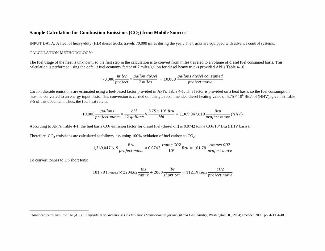
Sample Calculation for Combustion Emissions (CO2) from Mobile Sources1 INPUT DATA: A fleet of heavy-duty (HD) diesel trucks travels 70,000 miles during the year. The trucks are equipped with advance control systems. CALCULATION METHODOLOGY: The fuel usage of the fleet is unknown, so the first step in the calculation is to convert from miles traveled to a volume of diesel fuel consumed basis. This calculation is performed using the default fuel economy factor of 7 miles/gallon for diesel heavy trucks provided API’s Table 4-10.
70,000
7 10,000
Carbon dioxide emissions are estimated using a fuel-based factor provided in API’s Table 4-1. This factor is provided on a heat basis, so the fuel consumption must be converted to an energy input basis. This conversion is carried out using a recommended diesel heating value of 5.75×10⁶ Btu/bbl (HHV), given in Table 3-5 of this document. Thus, the fuel heat rate is:
10,000 42 5.75 10
1,369,047,619
According to API’s Table 4-1, the fuel basis CO2 emission factor for diesel fuel (diesel oil) is 0.0742 tonne CO2/106 Btu (HHV basis). Therefore, CO2 emissions are calculated as follows, assuming 100% oxidation of fuel carbon to CO2:
1,369,047,619 0.0742 2
10 101.78 2
To convert tonnes to US short tons:
101.78 2204.62 2000 112.19 2
1 American Petroleum Institute (API). Compendium of Greenhouse Gas Emissions Methodologies for the Oil and Gas Industry, Washington DC, 2004; amended 2005. pp. 4-39, 4-40.
Well Name and Number: (as shown on NYSDEC-issued well permit) API Number: Well Owner: Planned Frac Commencement Date:
Yes No
Well drilled, cased and cemented in accordance with well permit, or in accordance with revisions approved by the Regional Mineral Resources Manager on the dates listed below and revised wellbore schematic filed in regional Mineral Resources office.
Approval Date & Brief Description of Approved Revision(s) (attach additional sheets if necessary)
All depths where fresh water, brine, oil or gas were encountered or circulation was lost
during drilling operations are recorded on the attached sheet. Additional sheets are attached which describe how any lost circulation zones were addressed.
Enclosed cement bond log verifies top of cement and effective cement bond at least 500
feet above the top of the formation to be fractured or at least 300 feet into the previous casing string. If intermediate casing was used and not cemented to surface, or if intermediate casing was not used and production casing was not cemented to surface, then provide the date of approval by the Department and a brief description of justification.
Approval Date & Brief Description of Justification (attach additional sheets if necessary)
If fracturing operations will be performed down casing, then the pre-fracturing pressure test required by permit conditions will be conducted and fracturing operations will only commence if test is successful. Any unsuccessful test will be reported to the Department and remedial measures will be proposed by the operator and must be approved by the Department prior to further operations.
All other information collected while drilling, listed below, verifies that all observed gas
zones are isolated by casing and cement and that the well is properly constructed and suitable for high-volume hydraulic fracturing.
Date and Brief Description of Information Collected
(attach additional sheets if necessary)
Fracturing products used will be the same products identified in the well permit application materials or otherwise identified and approved by the Department.
I hereby affirm under penalty of perjury that information provided on this form is true to the best of my knowledge and belief. False statements made herein are punishable as a Class A misdemeanor pursuant to Section 210.45 of the Penal Law.
Printed or Typed Name and Title of Authorized Representative Signature, Date INSTRUCTIONS FOR PRE-FRAC CHECKLIST AND CERTIFICATION The completed and signed form must be received by the appropriate Regional office at least 48 hours prior to the commencement of fracturing operations. The operator may conduct fracturing operations provided 1) all items on the checklist are affirmed by a response of “Yes,” 2) the Pre-Frac Checklist And Certification is received by the Department at least 48 hours in advance and 3) all other pre-frac notification requirements are met as specified in permit conditions. The well owner is prohibited from conducting fracturing operations on the well without additional Department review and approval if a response of “No” is provided to any of the items in the pre-frac checklist.
SIGNATURE SECTION
Signature Section - The person signing the Pre-Frac Checklist and Certification must be authorized to do so by the Organizational Report on file with the Division.
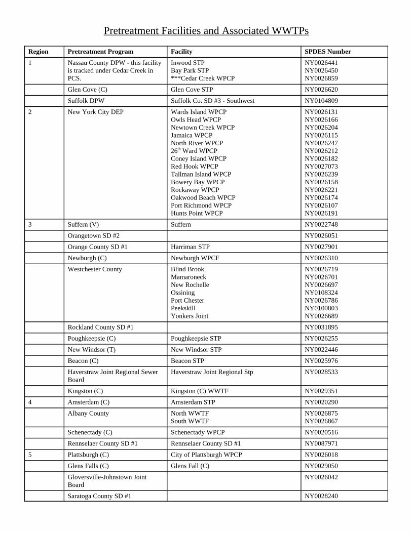
2 New York City DEP Wards Island WPCPOwls Head WPCPNewtown Creek WPCPJamaica WPCPNorth River WPCP26th Ward WPCPConey Island WPCPRed Hook WPCPTallman Island WPCPBowery Bay WPCPRockaway WPCPOakwood Beach WPCPPort Richmond WPCPHunts Point WPCP
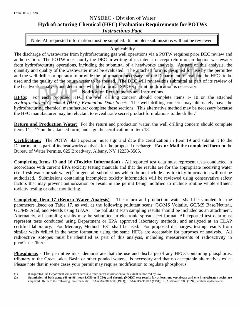
Form HFC (01/09) NYSDEC - Division of Water Hydrofracturing Chemical (HFC) Evaluation Requirements for POTWs Instructions Page
Note: All requested information must be supplied. Incomplete submissions will not be reviewed.
Applicability The discharge of wastewater from hydrofracturing gas well operations via a POTW requires prior DEC review and authorization. The POTW must notify the DEC in writing of its intent to accept return or production wastewater from hydrofracturing operations, including the submittal of a headworks analysis. As part of this analysis, the quantity and quality of the wastewater must be evaluated. The attached form is designed for use by the permittee and the well driller or operator to provide the information necessary for the Department to evaluate the HFCs to be used and the quality of the return water to be treated. The DEC will review this submittal as part of its review of the headworks analysis and determine whether a formal SPDES permit modification is necessary. Notification Requirements and Instructions HFCs: For each proposed HFC, the well drilling concern should complete items 1- 10 on the attached Hydrofracturing Chemical (HFC) Evaluation Data Sheet. The well drilling concern may alternately have the hydrofracturing chemical manufacturer complete these sections. This alternative method may be necessary because the HFC manufacturer may be reluctant to reveal trade secret product formulations to the driller.1 Return and Production Water: For the return and production water, the well drilling concern should complete items 11 – 17 on the attached form, and sign the certification in Item 18. Certification: The POTW plant operator must sign and date the certification in Item 19 and submit it to the Department as part of its headworks analysis for the proposed discharge. Fax or Mail the completed form to the Bureau of Water Permits, 625 Broadway, Albany, NY 12233-3505. Completing Items 10 and 16 (Toxicity Information) - All reported test data must represent tests conducted in accordance with current EPA toxicity testing manuals and that the results are for the appropriate receiving water (i.e. fresh water or salt water).2 In general, submissions which do not include any toxicity information will not be authorized. Submissions containing incomplete toxicity information will be reviewed using conservative safety factors that may prevent authorization or result in the permit being modified to include routine whole effluent toxicity testing or other monitoring. Completing Item 17 (Return Water Analysis) – The return and production water shall be sampled for the parameters listed on Table 17, as well as the following pollutant scans: GC/MS Volatile, GC/MS Base/Neutral, GC/MS Acid, and Metals using GFAA. The pollutant scan sampling results should be included as an attachment. Alternately, all sampling results may be submitted in electronic spreadsheet format. All reported test data must represent tests conducted using Department or EPA approved laboratory methods, and analyzed at an ELAP certified laboratory. For Mercury, Method 1631 shall be used. For proposed discharges, testing results from similar wells drilled in the same formation using the same HFCs are acceptable for purposes of analysis. All radioactive isotopes must be identified as part of this analysis, including measurements of radioactivity in picoCuries/liter. Phosphorus - The permittee must demonstrate that the use and discharge of any HFCs containing phosphorus, tributary to the Great Lakes Basin or other ponded waters, is necessary and that no acceptable alternatives exist. Please note that in some cases your permit may require modification to regulate phosphorus. (1) If requested, the Department will restrict access to trade secret information to the extent authorized by law. (2) Submission of both acute (48 or 96 hour LC50 or EC50) and chronic (NOEC) test results for at least one vertebrate and one invertebrate species are
required. Refer to the following three manuals: EPA/600/4-90/027F (1993); EPA/600/4-91/002 (1994); EPA/600/4-91/003 (1994); or their replacements.
NYSDEC - Division of Water Hydrofracturing Chemical (HFC) Evaluation Data Sheet
Page 1 of 3 TO BE COMPLETED BY DRILLING CONCERN OR HFC CHEMICAL SUPPLIER
Note: All requested information must be supplied. Incomplete submissions will not be reviewed.
1.a. Facility Name: 1.b. Facility Location: 2.a. Date Signed by Facility: 2.b. Date Signed by HFC Mfr: 3.a. HFC Name: 3.b. HFC Manufacturer: 4. HFC Function: 5. Method of onsite storage: 6.a. HFC Daily Dosage to well: average lbs/day = , maximum lbs/day = 7.a. HFC BOD: (lb/lb) - (mg/l) - 7.b. HFC COD: (lb/lb) - (mg/l) - 8.a. Is HFC a NYS registered biocide? 8.b. Registration Number - 9.a. HFC Composition - Ingredients/Impurities (note: ingredients/impurities must total to 100%)
9.b. % 9.c. CAS# 9.d. Injection Concentration
mg/l mg/l mg/l mg/l mg/l mg/l mg/l mg/l mg/l 10. HFC Toxicity Info (most sensitive species) - Attach description of endpoint for each EC50 and LOEC. 10.a. Vertebrate Species
LC50 EC50 Chronic NOEC Chronic LOEC Other -
mg/l mg/l mg/l mg/l
10.b. Invertebrate Species
LC50 EC50 Chronic NOEC Chronic LOEC Other -
mg/l mg/l mg/l mg/l
Form HFC (2/02) NYSDEC - Division of Water Hydrofracturing Chemical (HFC) Evaluation Data Sheet
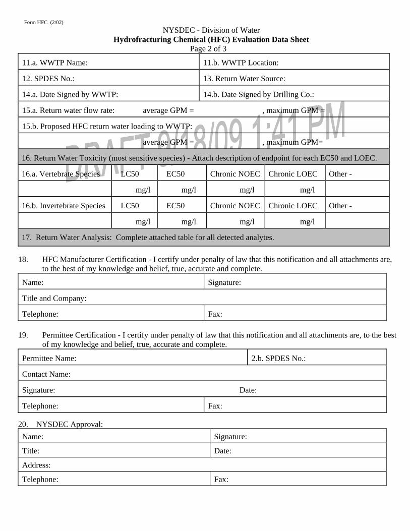
Page 2 of 3 11.a. WWTP Name: 11.b. WWTP Location: 12. SPDES No.: 13. Return Water Source: 14.a. Date Signed by WWTP: 14.b. Date Signed by Drilling Co.: 15.a. Return water flow rate: average GPM = , maximum GPM = 15.b. Proposed HFC return water loading to WWTP: average GPM = , maximum GPM= 16. Return Water Toxicity (most sensitive species) - Attach description of endpoint for each EC50 and LOEC. 16.a. Vertebrate Species
LC50
EC50 Chronic NOEC Chronic LOEC
Other -
mg/l
mg/l mg/l mg/l
16.b. Invertebrate Species
LC50
EC50 Chronic NOEC Chronic LOEC
Other -
mg/l
mg/l mg/l mg/l
17. Return Water Analysis: Complete attached table for all detected analytes.
18. HFC Manufacturer Certification - I certify under penalty of law that this notification and all attachments are, to the best of my knowledge and belief, true, accurate and complete.
Name: Signature: Title and Company: Telephone: Fax:
19. Permittee Certification - I certify under penalty of law that this notification and all attachments are, to the best
of my knowledge and belief, true, accurate and complete. Permittee Name: 2.b. SPDES No.: Contact Name: Signature: Date: Telephone: Fax:
17. Return Water Analysis: Complete the attached table for all analytes detected, and attach the results from the pollutant scans as listed in the instructions. Alternately, this information may be provided on an Excel spreadsheet listing the information in the table below.
WWTP Name: HFC Source: Proposed Start Date:
SPDES No.: NY WWTP Loading Rates, in lb/day Percent Removal Projected Effluent Quality
Parameter
Return Water Concentration
mg/l
Return Water
Loading
Present WWTP Loading
Total
WWTP Loading
Permitted WWTP Loading
Present WWTP
% Removal
Anticipated WWTP % Removal
Maximum Effluent Loading,
lb/day
Maximum Effluent
Concentration mg/l
pH, range, SU
Oil and Grease
Solids, Total Suspended
Solids, Total Dissolved
Chlo ride
Sulfate
Alkalinity, Total (CaCO3)
BOD, 5 day
Chemical Oxygen Demand (COD)
Total Kjeldahl Nitrogen (TKN)
Ammonia, as N
Total Organic Carbon
Phenols, Total
Radium (sum of all isotopes), pCi/l
Thorium, pCi/l
Uranium (sum of all isotopes)
Gross Alpha Radiation, pCi/l
Gross Beta Radiation, pCi/l
Please note that a log listing the date, volume, and source of all wastewater accepted from hydrofracturing activites shall be kept and submitted on a monthly basis as an attachment to the facility’s Discharge Monitoring Report.
TO: Peter Briggs, New York State Department of Environmental Conservation, Mineral Resources
FROM: Jerome Blackman, Natural Gas STAR International DATE: September 1, 2009 RE: Natural Gas Star This memo lists methane emission mitigation options applicable in exploration and production; in reference to your inquiry. Natural Gas STAR Partners have reported a number of voluntary activities to reduce exploration and production methane emissions, and major project types are listed and summarized below and may help focus your research as you review the resources available on the Natural Gas STAR website. In addition to these practices and technologies is an article that lists the same and several more cost effective options for producers to reduce methane emissions. Please refer to the link below. Cost-Effective Methane Emissions Reductions for Small and Midsize Natural Gas Producers www.epa.gov/gasstar/documents/CaseStudy.pdf Reduced Emission Completions Traditionally, “cleaning up” drilled wells, before connecting them to a production sales line, involves producing the well to open pits or tankage where sand, cuttings, and reservoir fluids are collected for disposal and the produced natural gas is vented to the atmosphere. Partners reported using a “green completion” method in which tanks, separators, dehydrators are brought on site to clean up the gas sufficiently for delivery to sales. The result is reducing completion emissions, creating an immediate revenue stream, and less solid waste. Partner Recommended Opportunity from the Natural Gas STAR website: www.epa.gov/gasstar/documents/greencompletions.pdf BP Experience Presentation with Reduced Emission Completions www.epa.gov/gasstar/documents/workshops/2008-annual-conf/smith.pdf Green Completion Presentation from a Tech-Transfer Workshop in 2005 at Houston, TX www.epa.gov/gasstar/documents/workshops/houston-2005/green_c.pdf Optimize Glycol Circulation and Install of Flash Tank Separators in Dehydrator In dehydrators, as triethylene glycol (TEG) absorbs water, it also absorbs methane, other volatile organic compounds (VOCs), and hazardous air pollutants (HAPs). When the TEG is regenerated through heating, absorbed methane, VOCs, and HAPs are vented to the atmosphere with the water, wasting gas and money. Many wells produce gas below the initial design capacity yet
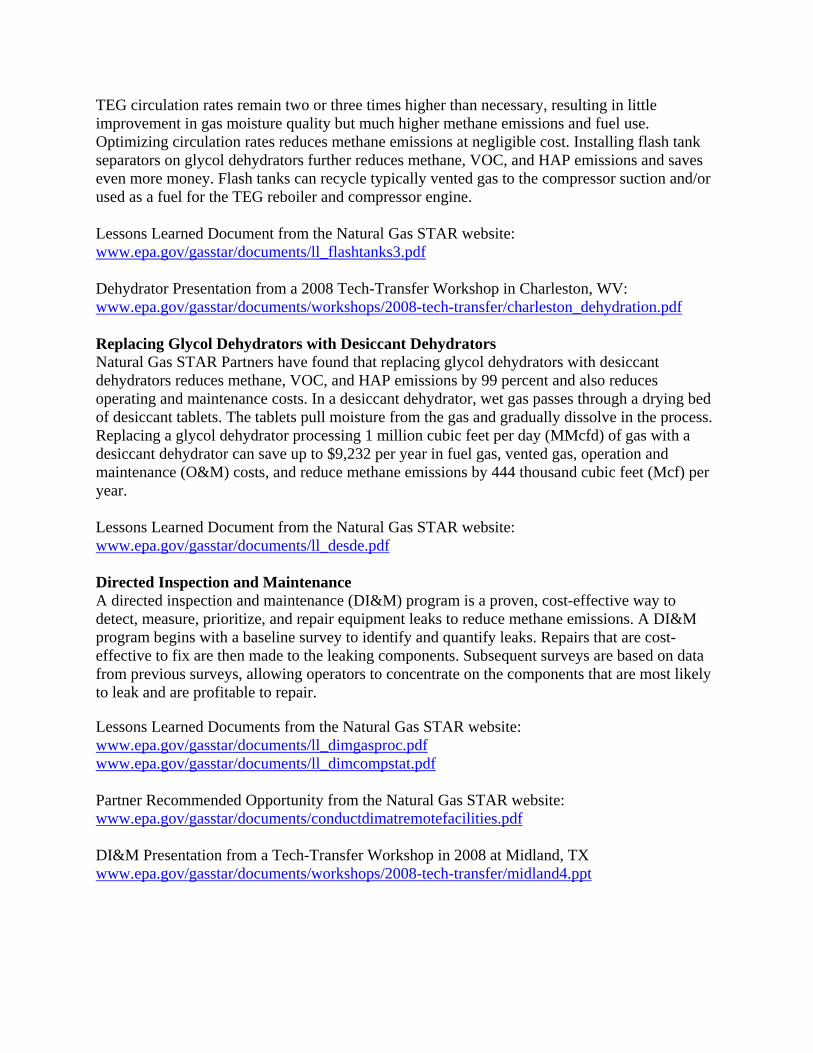
TEG circulation rates remain two or three times higher than necessary, resulting in little improvement in gas moisture quality but much higher methane emissions and fuel use. Optimizing circulation rates reduces methane emissions at negligible cost. Installing flash tank separators on glycol dehydrators further reduces methane, VOC, and HAP emissions and saves even more money. Flash tanks can recycle typically vented gas to the compressor suction and/or used as a fuel for the TEG reboiler and compressor engine. Lessons Learned Document from the Natural Gas STAR website: www.epa.gov/gasstar/documents/ll_flashtanks3.pdf Dehydrator Presentation from a 2008 Tech-Transfer Workshop in Charleston, WV: www.epa.gov/gasstar/documents/workshops/2008-tech-transfer/charleston_dehydration.pdf Replacing Glycol Dehydrators with Desiccant Dehydrators Natural Gas STAR Partners have found that replacing glycol dehydrators with desiccant dehydrators reduces methane, VOC, and HAP emissions by 99 percent and also reduces operating and maintenance costs. In a desiccant dehydrator, wet gas passes through a drying bed of desiccant tablets. The tablets pull moisture from the gas and gradually dissolve in the process. Replacing a glycol dehydrator processing 1 million cubic feet per day (MMcfd) of gas with a desiccant dehydrator can save up to $9,232 per year in fuel gas, vented gas, operation and maintenance (O&M) costs, and reduce methane emissions by 444 thousand cubic feet (Mcf) per year. Lessons Learned Document from the Natural Gas STAR website: www.epa.gov/gasstar/documents/ll_desde.pdf Directed Inspection and Maintenance A directed inspection and maintenance (DI&M) program is a proven, cost-effective way to detect, measure, prioritize, and repair equipment leaks to reduce methane emissions. A DI&M program begins with a baseline survey to identify and quantify leaks. Repairs that are cost-effective to fix are then made to the leaking components. Subsequent surveys are based on data from previous surveys, allowing operators to concentrate on the components that are most likely to leak and are profitable to repair. Lessons Learned Documents from the Natural Gas STAR website: www.epa.gov/gasstar/documents/ll_dimgasproc.pdf www.epa.gov/gasstar/documents/ll_dimcompstat.pdf Partner Recommended Opportunity from the Natural Gas STAR website: www.epa.gov/gasstar/documents/conductdimatremotefacilities.pdf DI&M Presentation from a Tech-Transfer Workshop in 2008 at Midland, TX www.epa.gov/gasstar/documents/workshops/2008-tech-transfer/midland4.ppt
Complete information on the Natural Gas STAR Program is given in USEPA’s web site (http://epa.gov/gasstar/index.html)
• Participation in the program is voluntary.
• Program outreach is provided through the web site, annual national two-day implementation workshop, and sector– or activity – specific technology transfer workshops or webcasts, often with a regional focus (approximately six to nine per year).
• Companies agreeing to join (“Partners”) commit to evaluating Best Management Practices
(BMP) and implementing them when they are cost-effective for the company. In addition, “ …partners are encouraged to identify, implement, and report on other technologies and practices to reduce methane emissions (referred to as Partner Reported Opportunities or PROs ).”
• Best Management Practices are a limited set of reduction measures identified at the initiation
of the program as widely applicable. PROs subsequently reported by partners have increased the number of reduction measures.
• The program provides calculation tools for estimating emissions reductions for BMPs and
PROs, based on the relevant features of the equipment and application.
• Projected emissions reductions for some measures can be estimated accurately and simply; for example, reductions from replacing high-bleed pneumatic devices with low-bleed devices are a simple function of the known bleed rates of the respective devices, and the methane content of the gas. For others, such as those involving inspection and maintenance to detect and repair leaks, emissions reductions are difficult to anticipate because the number and magnitude of leaks is initially unknown or poorly estimated.
• Tools are also provided for estimating the economics of emission reduction measures, as a
function of factors such as gas value, capital costs, and operation and maintenance costs.
• Technical feasibility is variable between measures and is often site- or application- specific. For example, in the Gas STAR Lessons Learned for replacing high-bleed with low-bleed pneumatic devices, it is estimated that “nearly all” high-bleed devices can feasibly be replaced with low-bleed devices. Some specific exceptions are listed, including very large valves requiring fast and/or precise response, commonly on large compressor discharge and bypass controllers.
• Partners report emissions reductions annually, but the individual partner reports are
confidential. Publicly reported data are aggregated nationally, but include total reductions by sector and by emissions reduction measure.
1 New Mexico Environment Department, Oil and Gas Greenhouse Gas Emissions Reductions. December 2007, pp. 19-20.
High prices and high demand for natural gas, have seen the natural gas production industry move into development of the more technologically challenging unconventional gas reserves such as tight sands, shale and coalbed methane. Completion of new wells and re-working (workover) of existing wells in these tight formations typically involve hydraulic fracturing of the reservoir to increase well productivity. Removing the water and excess proppant (generally sand) during completion and well clean-up may result in significant releases of natural gas and methane emissions to the atmosphere (The 40 BCF value is an extension of BP’s venting for well-bore deliquification scaled up for the entire basin. It is not due to well clean-up post fracture stimulation).
Conventional completion of wells (a process that cleans the well bore of drill cuttings and
fluid and fracture stimulation fluids and solids so that the gas has a free path from the reservoir) resulted in gas being either vented or flared. Vented gas resulted in large amounts of methane, volatile organic compounds (VOCs), and hazardous air pollutants (HAPs) emissions being released to the atmosphere, while flared gas resulted in carbon dioxide emissions.
Reduced emissions completions (RECs) – also known as reduced flaring completions or
green completions – is a term used to describe an alternate practice that captures gas produced during well completions and well workovers following hydraulic fracturing. Portable equipment is brought on site to separate the gas from the solids and liquids produced during the completion and process this gas suitably for injection into the sales pipeline. Reduced emissions completions help to mitigate methane, VOC, and HAP emissions during well cleanup and can eliminate or significantly reduce the need for flaring.
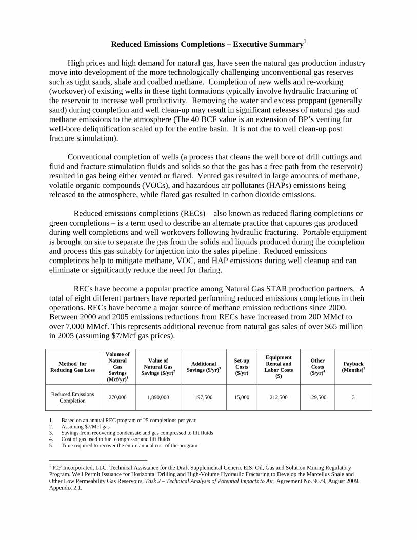
RECs have become a popular practice among Natural Gas STAR production partners. A total of eight different partners have reported performing reduced emissions completions in their operations. RECs have become a major source of methane emission reductions since 2000. Between 2000 and 2005 emissions reductions from RECs have increased from 200 MMcf to over 7,000 MMcf. This represents additional revenue from natural gas sales of over $65 million in 2005 (assuming $7/Mcf gas prices).
1. Based on an annual REC program of 25 completions per year 2. Assuming $7/Mcf gas 3. Savings from recovering condensate and gas compressed to lift fluids 4. Cost of gas used to fuel compressor and lift fluids 5. Time required to recover the entire annual cost of the program
1 ICF Incorporated, LLC. Technical Assistance for the Draft Supplemental Generic EIS: Oil, Gas and Solution Mining Regulatory Program. Well Permit Issuance for Horizontal Drilling and High-Volume Hydraulic Fracturing to Develop the Marcellus Shale and Other Low Permeability Gas Reservoirs, Task 2 – Technical Analysis of Potential Impacts to Air, Agreement No. 9679, August 2009. Appendix 2.1.
New York State Division of Mineral Resources
Appendix 26
Instructions for Using The
On-Line Searchable Database To Locate Drilling Applications
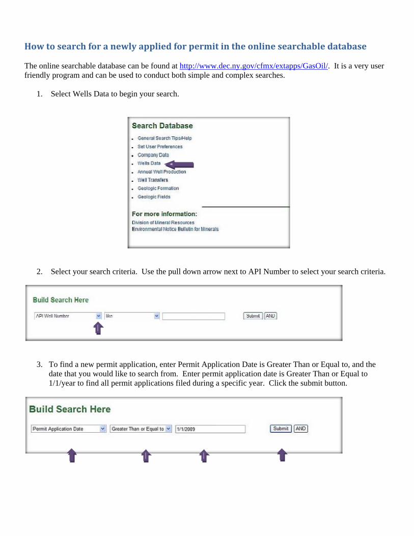
How to search for a newly applied for permit in the online searchable database The online searchable database can be found at http://www.dec.ny.gov/cfmx/extapps/GasOil/. It is a very user friendly program and can be used to conduct both simple and complex searches.
1. Select Wells Data to begin your search.
2. Select your search criteria. Use the pull down arrow next to API Number to select your search criteria.
3. To find a new permit application, enter Permit Application Date is Greater Than or Equal to, and the date that you would like to search from. Enter permit application date is Greater Than or Equal to 1/1/year to find all permit applications filed during a specific year. Click the submit button.
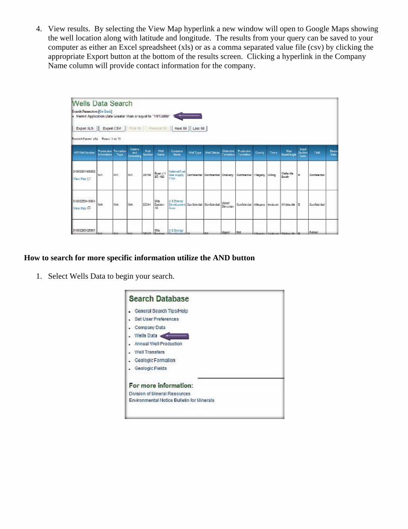
4. View results. By selecting the View Map hyperlink a new window will open to Google Maps showing the well location along with latitude and longitude. The results from your query can be saved to your computer as either an Excel spreadsheet (xls) or as a comma separated value file (csv) by clicking the appropriate Export button at the bottom of the results screen. Clicking a hyperlink in the Company Name column will provide contact information for the company.
How to search for more specific information utilize the AND button
1. Select Wells Data to begin your search.
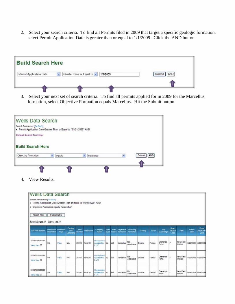
2. Select your search criteria. To find all Permits filed in 2009 that target a specific geologic formation, select Permit Application Date is greater than or equal to 1/1/2009. Click the AND button.
3. Select your next set of search criteria. To find all permits applied for in 2009 for the Marcellus formation, select Objective Formation equals Marcellus. Hit the Submit button.
4. View Results.
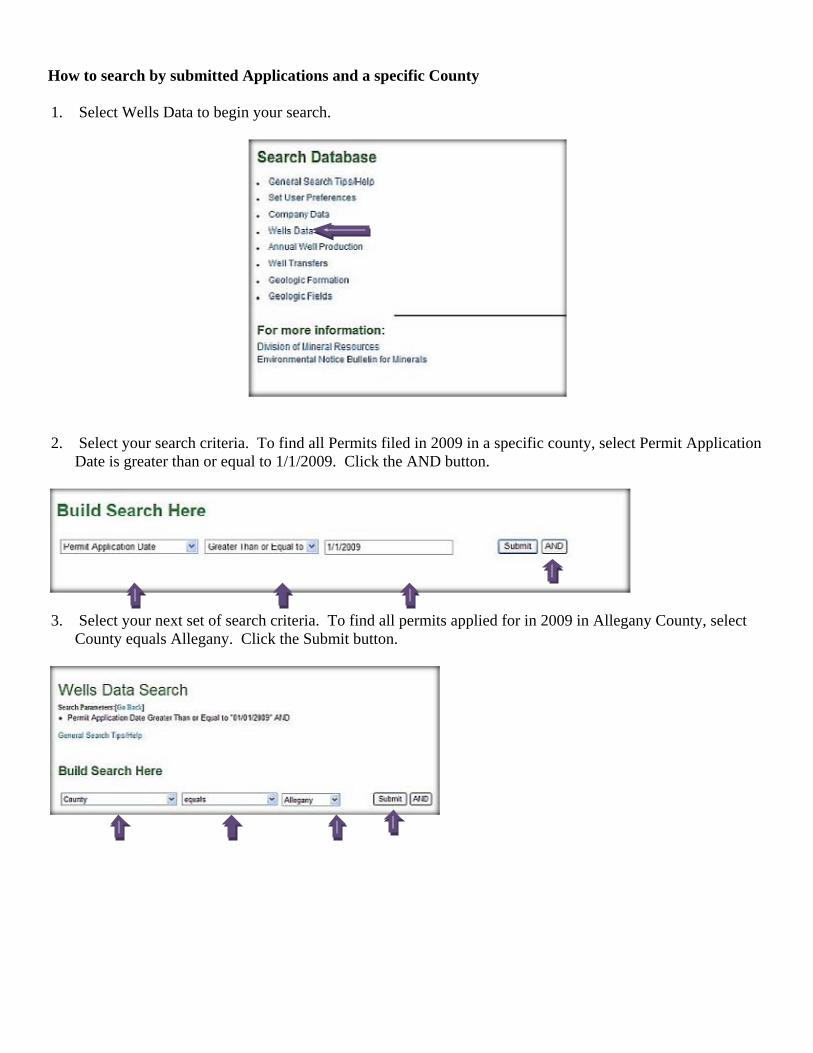
How to search by submitted Applications and a specific County 1. Select Wells Data to begin your search.
2. Select your search criteria. To find all Permits filed in 2009 in a specific county, select Permit Application
Date is greater than or equal to 1/1/2009. Click the AND button.
3. Select your next set of search criteria. To find all permits applied for in 2009 in Allegany County, select