ALASKA LNG PROJECT DOCKET NO. CP17-___-000 RESOURCE REPORT NO. 11 APPENDIX A –ENVIRONMENTAL INFORMATION FOR STRAIN-BASED DESIGN SPECIAL PERMIT DOCUMENT NUMBER DATE: APRIL 14, 2017 REVISION: 0 PUBLIC APPENDIX A ENVIRONMENTAL INFORMATION FOR STRAIN- BASED DESIGN SPECIAL PERMIT
Transcript
ALASKA LNG PROJECT
DOCKET NO. CP17-___-000 RESOURCE REPORT NO. 11
APPENDIX A –ENVIRONMENTAL INFORMATION FOR STRAIN-BASED DESIGN
SPECIAL PERMIT
DOCUMENT NUMBER DATE: APRIL 14, 2017
REVISION: 0
PUBLIC
APPENDIX A ENVIRONMENTAL INFORMATION FOR STRAIN-BASED DESIGN SPECIAL PERMIT
Appendix A
Environmental Information for Strain Based Design Special Permit
The purpose of this enclosure is to augment the National Environmental Policy Act analysis presented in the Alaska LNG Project Federal Energy Regulatory Commission Resource Reports (FERC RR) with information that meets specific U.S. Department of Transportation, Pipeline and Hazardous Materials Safety Administration (PHMSA) requirements for a special permit as described in 49 Code of Federal Regulations (CFR) § 190.341. The Special Permit Conditions for usage of strain-based design and this enclosure are also included together as Appendices A and B to the Alaska LNG FERC Resource Report 11, Reliability and Safety.
I. Purpose and Need Alaska LNG is proposing to build a Mainline pipeline (the pipeline or the Mainline) to transport natural gas to a proposed Liquefied Natural Gas (LNG) facility from a proposed gas treatment plant located on Alaska’s North Slope. The Federal Energy Regulatory Commission (the FERC) is the lead Federal agency. The Federal Department of Transportation’s Pipeline and Hazardous Materials Safety Administration (PHMSA) has authority over the design and operation of natural gas transmission pipelines under 49 CFR Part 192. 49 CFR Part 192 includes specific regulatory requirements for the design, construction, operation, and maintenance of natural gas pipelines to maintain safety. If required, special permits can be granted under 49 CFR §190.341 for proposed deviations from established pipeline standards. PHMSA imposes conditions on the grant of special permits to assure safety and environmental protection in accordance with 49 CFR § 190.341. PHMSA is required to comply with the National Environmental Policy Act (NEPA) in deciding whether to issue the special permit.
Alaska LNG is seeking exemption from the requirements of 49 CFR § 192.103 in regions of discontinuous permafrost. These regions will result in time dependent ground movement, which would require that that pipe be built with heavy walled pipe with sufficient thickness to withstand the external forces of ground freezing and thawing, otherwise known as frost heave and thaw settlement, respectively. While pipelines transporting warm oil (e.g. Trans Alaska Pipeline System: TAPS) can mitigate these forces through an aboveground pipeline, a high pressure gas pipeline built above ground would require prohibitively expensive steel metallurgy to ensure pipeline integrity commensurate to fulfill the requirements of 49 CFR § 192.53 at temperatures as low as -50˚F.
Therefore, Alaska LNG intends to request a Special Permit from PHMSA to allow Strain-Based Design of this segment of the pipeline. Strain-Based Design (SBD) involves enhanced metallurgy and engineering to allow the pipe to deform in the longitudinal direction while maintaining its integrity and safety. SBD is a technology that enables compliance with 49 CFR § 192.53, which requires that materials are “able to maintain the structural integrity of the pipeline under temperature and other environmental conditions that may be anticipated”.
A Special Permit would allow Alaska LNG to design and construct the pipeline using Strain-Based Design for discrete segments of the pipeline. The Special Permit would include conditions
Appendix A
Environmental Information for Strain Based Design Special Permit
to ensure the pipeline has equal or greater safety than a pipeline constructed in accordance with 49 CFR Part 192.
II. Background and Site Description Figure 1 shows the proposed Mainline route from the proposed gas treatment plant located at Prudhoe Bay to the proposed LNG Plant site located on the Kenai Peninsula. The Mainline would be a 42-inch-diameter natural gas pipeline, approximately 807 miles in length, extending from the Alaska LNG’s Gas Treatment Plant (GTP) on the North Slope to the Liquefaction Facility on the shore of Cook Inlet near Nikiski, including an offshore pipeline section crossing Cook Inlet. The onshore pipeline would be a buried pipeline with the exception of short above-ground special design segments, such as aerial water crossings and aboveground fault crossings. As presented in Table 1.3.2-1 of FERC Resource Report 1, the Mainline would originate in the North Slope Borough, traverse the Yukon-Koyukuk Census Area, the Fairbanks North Star Borough, the Denali Borough, the Matanuska-Susitna Borough, and the Kenai Peninsula Borough, and terminate at the Liquefaction Facility. The Mainline’s proposed design has a maximum allowable operating pressure (MAOP) of 2,075 psig.
The Mainline would include several types of aboveground pipeline facilities. The proposed design includes eight compressor stations, four meter stations, multiple pig launching/receiving stations, multiple Mainline block valves (MLBV), and five potential gas interconnection points. A list of compressor stations, heater station, and meter stations is provided in Table 1.3.2-6 of FERC Resource Report 1.
Approximately 36 percent of the Mainline route is collocated within 500 feet of an existing ROW, to include TAPS and other pipelines, highways or major roads, utilities and railroads. Table 1.3.2-2 of FERC Resource Report 1 summarizes collocation of the Mainline route that are within 500 feet of highways, major roads, the Trans-Alaska Pipeline System (TAPS), other pipeline ROWs, utilities, and railroads. The Mainline crosses TAPS 12 times, the TAPS Fuel Gas Line 5 times, and has four railroad crossings. Design of the road and railroad crossings would be validated for applicability of the minimum wall thickness requirements for service loads on crossings in accordance with API RP 1102, using the appropriate design factor for the design class location, and comply with 49 CFR § 192.111. The minimum depth of cover would be four feet for road crossings as specified by the Alaska Administrative Code 17.AAC 15.211 “Underground Facilities” and 10 feet for railroad crossings, as specified in Alaska Railroad Corporation (ARRC) standards below travel surface (this exceeds the 49 CFR § 192.327(a) requirement which requires a minimum of three feet at drainage ditches of public roads and railroads). Site-specific designs for major highway and railroad crossings will be provided in Appendix H of the FERC application. Additional details on roads, railroads, pipelines, utilities, and power lines crossings can be found in FERC Resource Report 8.
Appendix A
Environmental Information for Strain Based Design Special Permit
Aerial crossings on pipeline specific bridges (i.e. bridges that carry only a pipeline) are located at Nenana River at Moody and Lynx Creek. The design factor for the pipeline at aerial crossings will comply with 49 CFR § 192.111.
Pipeline design standards in 49 CFR § 192.5(a)(1) are based on “class location units,” which classify locations based on population density in the vicinity of an existing or proposed pipeline system. The lower the class location (1-4), the higher the design factor used to find the minimum required wall thickness for pressure containment, i.e. the required minimum thickness of the pipe increases as the Class location. 99% of the Mainline route is in Class 1, which is defined as having 10 or fewer buildings intended for human occupancy located within 220 yards on either side of any continuous 1-mile length of pipeline. On the Kenai Peninsula, near Nikiski, there is a Class 2 location that is about 2.6 miles long. Also on the Kenai Peninsula there is a potential Class 3 location as the Mainline nears the LNG Plant. In the Nenana Canyon region of Denali National Park (~MP 536) there is approximately a half a mile of Class 3. Additional details on class locations for the Mainline can be found in FERC Resource Report 11, Section 11.7.
There are 10 potential high consequence areas (HCA) along the Mainline as defined under 49 CFR § 192.903. This includes two HCAs that are based on the aforementioned Class 3 locations. The remaining HCAs are located in Class 1 locations, details of which can be found in FERC Resource Report 11, Section 11.7. In addition, the pipeline route segments that are addressed in this Special Permit for Strain Based Design (the “Strain Based Design segments”) will be incorporated into the integrity management program (IMP), and treated as a covered segment in a high consequence area (HCA) in accordance with 49 CFR Part 192, Subpart O, and the Special Permit Conditions.
The construction right of way (ROW) width will vary depending on the type of terrain, the season of construction, and the ease of access from nearby roads. The permanent ROW width would be 50 feet plus the diameter of the pipeline, i.e. 53-1/2 feet. Greater details on construction ROW can be found in FERC Resource Report 1. The Mainline would be sited on land composed of more than 85 percent federal, State of Alaska, and borough land of various holdings, with the remainder on privately owned land (see Resource Report 8).
The proposed gas pipeline corridor spans five physiographic regions including the Arctic Coastal Plain, Arctic Foothills, Brooks Range, Yukon-Tanana Upland, and Tanana-Kuskokwim Lowland. These regions host a variety of ecosystems including muskeg bogs, spruce upland forest, alpine and Arctic tundra, high brush, and bottomland spruce and poplar forests. The associated ecosystems support a variety of species which include grizzly and black bears, arctic foxes, seals, caribou, moose, small terrestrial mammals, birds, and anadromous fish. A variety of marine mammals inhabit the coastal waters in the Project area, including the bowhead whale, polar bear, beluga whale, ringed seal, bearded seal, Stellar sea lion, harbor seal, ribbon seal and spotted seal. Some of these species are critical subsistence resources for Alaska Native peoples.
Appendix A
Environmental Information for Strain Based Design Special Permit
A detailed description of the Mainline ROW is included in Section 1.3.2.1 of FERC Resource Report 1. Supporting facilities are described in Section 1.3.2.1.3 and temporary construction infrastructure is described in Section 1.3.2.4 of FERC Resource Report 1. Baseline environmental conditions and the analysis of environmental effects resulting from construction and operation of the Mainline are addressed by individual resources as follows:
• Resource Report 2 (Water Use and Quality).
• Resource Report 3 (Fish, Wildlife and Vegetation).
• Resource Report 4 (Cultural Resources)
• Resource Report 5 (Socioeconomics)
• Resource Report 6 (Geological Resources)
• Resource Report 7 (Soils)
• Resource Report 8 (Land Use, Recreation and Aesthetics)
• Resource Report 9 (Air and Noise Quality)
The pipeline will traverse areas potentially subject to geotechnical hazards (geohazards). Broadly defined, a geohazard is a geological and/or environmental condition with the potential to cause distress or damage to civil works. Geohazards of particular interest for the Alaska LNG pipeline are time dependent, such as thaw settlement and frost heave. The geohazard from fault displacement, which is time independent, is not expected to be of concern for strain based design due to the design/construction approach; that is, the active faults on the alignment will be crossed via an aboveground mode designed to allow for fault displacement without exceeding the 0.5% axial strain criteria for strain based design.
Thaw settlement may occur when ice-rich frozen ground temperature increases as a result of the disturbance to the surface vegetative mat and/or an elevated temperature of the pipeline, causing ground subsidence as the soil melts. The melting of previously permanently frozen (permafrost), ice-rich (i.e., contains ice in excess of the volume required to fill the pore space in an unfrozen state) soils results in soil consolidation or settlement, the magnitude of which is dependent on the type of soil and ice content. The settlement displacement divided by the initial thickness of the frozen soil layer which is thawed is denoted as “thaw strain”.
Frost heave occurs as a result of ice lens formation from freezing of the previously unfrozen soil beneath the pipe. As the chilled pipe extracts heat from the unfrozen soil, a frost bulb develops around the pipe. The interface between the unfrozen soil and the frost bulb is the frost front. Capillary action between the ice and water at the soil pore-scale causes water to be drawn to the
Appendix A
Environmental Information for Strain Based Design Special Permit
frost front during the freezing process, forming discrete ice-lenses within the frost bulb around the pipe. The volumetric expansion of the soil within the frost bulb from the discrete ice lenses causes an upward displacement of the frost bulb and the pipe itself. Frost heave requires three simultaneous conditions:
1. availability of groundwater for ice lens formation at the frost front;
2. an unfrozen "frost susceptible” soil; and
3. a cold pipe (below 30ºF) capable of advancing the frost bulb beneath the soil.
Frost susceptible soils are fine-grained silt and clay soils which freeze over a temperature range below the freezing point of water (32°F) and as such develop water suction at the frost front. Granular sand and gravel soils are not frost heave susceptible because these soils develop only minimal suction at the frost front due to relatively large pore size. Natural soils that are already frozen are not considered frost susceptible for pipeline design because water migration in frozen soils is negligible. However, for purposes of evaluating heave potential, all soils in the discontinuous zone are conservatively assumed to be unfrozen.
Frost heave and thaw settlement are not intrinsic threats to pipe integrity. Pipe integrity concerns arise when the displacement from the soil movement is not uniform along the pipeline, such as when a heaving segment of pipe is adjacent to a non-heaving segment, and the pipe has to bend to conform to this differential displacement. Differing amounts of settlement/heave displacement along the alignment may then cause longitudinal bending in the pipe resulting in strains in excess of 0.5% (the pipe material’s yield strength, which is defined at 0.5% strain). The potential displacement caused by these conditions can be addressed through the use of the use of SBD, heavier walled pipe, an above-ground pipeline, route avoidance, soil remediation or other mitigative mode as appropriate for the route segment and local conditions. Soils that are only seasonally frozen (the near surface soil layers freeze during winter along the entire pipeline alignment) will not cause displacement of the bottom of the pipe ditch and thus will not affect pipe longitudinal bending.
Alaska LNG and PHMSA recognize that the presence of discontinuous permafrost between MP 180 and MP 570 could potentially result in thaw settlement (for a frozen segment subjected to surface disturbance and/or a warm pipe in soils with high thaw strains) or frost heave (for a thawed segment with a chilled pipe in soils with high frost susceptibility) causing longitudinal pipe strains in excess of 0.5%. 49 CFR Part 192.103 states: “Pipe must be designed with sufficient wall thickness, or must be installed with adequate protection, to withstand anticipated external pressures and loads that will be imposed on the pipe after installation.” Alaska LNG is proposing to design, install, and operate the pipeline for identified segments that could pose an integrity threat in the discontinuous permafrost region using an SBD approach. The SBD approach would add specific material specifications, testing and acceptance protocols, and additional requirements for construction and operations that will provide adequate protection to
Appendix A
Environmental Information for Strain Based Design Special Permit
account for these strains from settlement or heave, in lieu of a heavy walled pipe or other mitigation alternatives. Because current regulations do not exist for the use of SBD a Special Permit would be required. SBD includes factors and conditions to ensure the design and safety considerations described under 49 CFR §§ 192.103, 192.105, 192.111, 192.112, 192.317, 192.328 and 192.619.
III. Alternatives For PHMSA’s environmental assessment pursuant to NEPA, the “No Action” alternative reflects a pipeline design that would not require issuance of a Special Permit. The Proposed Action alternative reflects Alaska LNG’s SBD for which a Special Permit with conditions would be issued.
An applicant requesting a Special Permit from PHMSA has the option of building a pipeline which would not require PHMSA to issue a Special Permit. This would require the design, construction, and operation of a pipeline in compliance with Part 192 and would not be subject to longitudinal bending that results in pipe longitudinal strains above 0.5%. The two alternatives are described below.
a. No Action Alternative – Construct the pipeline using engineering and construction techniques to mitigate the longitudinal bending resulting from pipe displacement. In lieu of SBD, one or a combination of two or more of the following techniques would be employed to mitigate the thaw settlement geohazard:
i. Belowground (burial) using extra heavy wall pipe (~1.000-inch in thickness) – This would be considered the primary alternative option. Heavy wall pipe allows the pipe to resist soil movement and conform more gradually to differential displacement of the ditch bottom. This technique could be employed in areas where the heavy wall pipe can be demonstrated to withstand strains resulting from permafrost related geohazards, where the lateral extent of the permafrost is limited, and where the depth to a stable soil strata is greater than practical for complete removal and replacement of the overlaying soils, or other areas considered practical. Heavy-walled pipe is not favored due to its increased cost, challenges with pipe handling and welding.
ii. Removal and replacement of thaw unstable material – This technique (over excavation) would be employed only in areas where very high soil movements due to thaw settlement or frost heave in near surface soils are evident, such as massive ice directly under the ditch. This mitigating approach could be combined with option (i), i.e. installation of heavy-walled pipe. The problematic soils would be removed and replaced with imported stable materials. This would require deeper and wider trenches than would be necessary with a SBD pipeline, and would also require the mining and importation of additional select fill material to backfill the trench below the pipe and disposal of the removed
Appendix A
Environmental Information for Strain Based Design Special Permit
material. This technique is of limited value since the magnitude of soil movement required to cause high pipe strains implies a required excavation depth in normal soils of over ten feet below ditch bottom.
iii. Installation of thermosyphons - In some areas, free-standing vertical pipes that extract
heat from the subsurface could be employed to stabilize in situ frozen segments or create new frozen segments dependent on the site specific requirements. These “thermosyphons” are passive heat exchangers that employ natural convection to chill the subsurface soils, and have been successfully used on the existing Trans Alaska Pipeline System (TAPS) to stabilize the frozen soil in potential thaw settlement areas. Although thermosyphons are inactive during the summer, they can act to cool the ground during the winter enough to where, in the summer, the ground remains frozen. They can also be employed to “pre-freeze” soils of potential frost heave segments, thus avoiding potential deleterious effects of an operating chilled pipeline. Similar to above-ground pipeline installation, the installation of thermosyphons is not generally favored because of visual impacts, potential disruption of animal migration and movement, safety and security concerns associated with exposed aboveground section of the thermosyphon, and the increased cost of installation.
iv. Aboveground installation – This technique requires installation of support structures to
elevate the pipeline a sufficient height above the ground surface to limit thermal interaction between the pipe and the soil. This technique might be employed in areas where heavy wall pipe is not sufficient to reduce the longitudinal bending of the pipe to acceptable levels, and the depth to a stable soil strata is greater than practical for complete removal and replacement of the problematic soils, or in other areas considered practical. Above-ground pipeline installation is not favored because of the increased cost of installation (vertical support members), visual impacts, potential disruption of animal migration and movement, pipeline safety and security concerns associated with exposed pipe, operational challenges handling large volumes of hydrocarbon liquid drop-out, and advanced line pipe steel technology to obtain suitable mechanical properties at -50˚F.
For purposes of the impact analysis, it is assumed that substantial segments of the pipeline would be built belowground with additional heavy walled pipe. Further, it is also assumed that design, and construction mitigation measures would be employed, along with strain remediation during operation as practical/necessary.
b. Proposed Action Alternative – Design, construct, operate, and maintain the pipeline in compliance with the Special Permit conditions, which will ensure that the pipeline will continue to function effectively and safely, even if thaw settlement or frost heave and
Appendix A
Environmental Information for Strain Based Design Special Permit
consequent longitudinal bending in excess of 0.5% would occur. The SBD Special Permit conditions will require specific materials, engineering, construction, and operations and maintenance (O&M) procedures for mitigation where pipe displacement due to thaw settlement or frost heave result in longitudinal bending strains which exceed allowed limits (0.5%) in the specified SBD segments.
i. Explain what the special permit application asks for.
Because PHMSA’s current regulations do not address strain based design, additional conditions are warranted to address anticipated external loads, and/or route hazards, that could cause a pipe to move or sustain longitudinal loads that require consideration of high strains. Such additional conditions are contemplated under 49 CFR § 192.103 and 49 CFR § 192.317. Alaska LNG requests that PHMSA issue a Special Permit to incorporate the additional conditions.
The Special Permit application covers the use of strain based design and assessment (SBDA) to address longitudinal bending of the pipe due to permanent ground deformations. For the proposed action, the time dependent geohazards that requires the use of SBD are thaw settlement and frost heave. The pipeline would be constructed of 42-inch diameter API 5L Grade X-70 pipe with a minimum wall thickness of 0.862-inch used in all segments identified as requiring SBD. For an MAOP of 2,075 psi, the wall thickness corresponds to a design factor of 0.72.
The use of SBD techniques would supplement the requirements of 49 CFR Part 192, which does not address longitudinal loadings above 0.5% such as those resulting from permanent ground deformations. Since SBD is not covered by 49 CFR Part 192 or any pipeline standards, additional conditions are warranted to address these loadings.
ii. Cite regulation(s) for which special permit is sought in accordance with 49 CFR § 190.341:
49 C.F.R. §§ 192.53, 192.103 and 192.317
iii. Explain/summarize how the design/operation/maintenance of the pipeline operating under the SP would differ from the pipeline in the no action alternative.
In addition to applicable requirements under 49 CFR Part 192, a pipeline utilizing SBD would be subject to more rigorous materials testing, construction, and O&M monitoring requirements defined in the SBD special permit conditions and specifications and procedures developed by Alaska LNG. As part of the design phase, Alaska LNG will further develop their preliminary material specifications which address the requirements
Appendix A
Environmental Information for Strain Based Design Special Permit
of high strain behavior and perform additional material testing, including additional full scale tests, to establish tensile and compressive strain capacities for the pipeline material procured as per the developed Material Specifications. During the construction phase, Alaska LNG will complete comprehensive construction and weld procedure qualifications and non-destructive testing of all welds that augment the pre-qualification work performed to date and presented to PHMSA. Additionally, an extensive Quality Assurance and Quality Control program for pipe installation, with emphasis on girth welds, 100% nondestructive examination (NDE) of all girth welds, and records of all field welding is required. During the operation phase, Alaska LNG will implement comprehensive monitoring to identify potential high strain conditions and implement appropriate corrective action, as required, to ensure the safe operation of the pipeline. Additional detail on the requirements for design, construction, and operation is provided in Section VII of this document and the Special Permit Conditions.
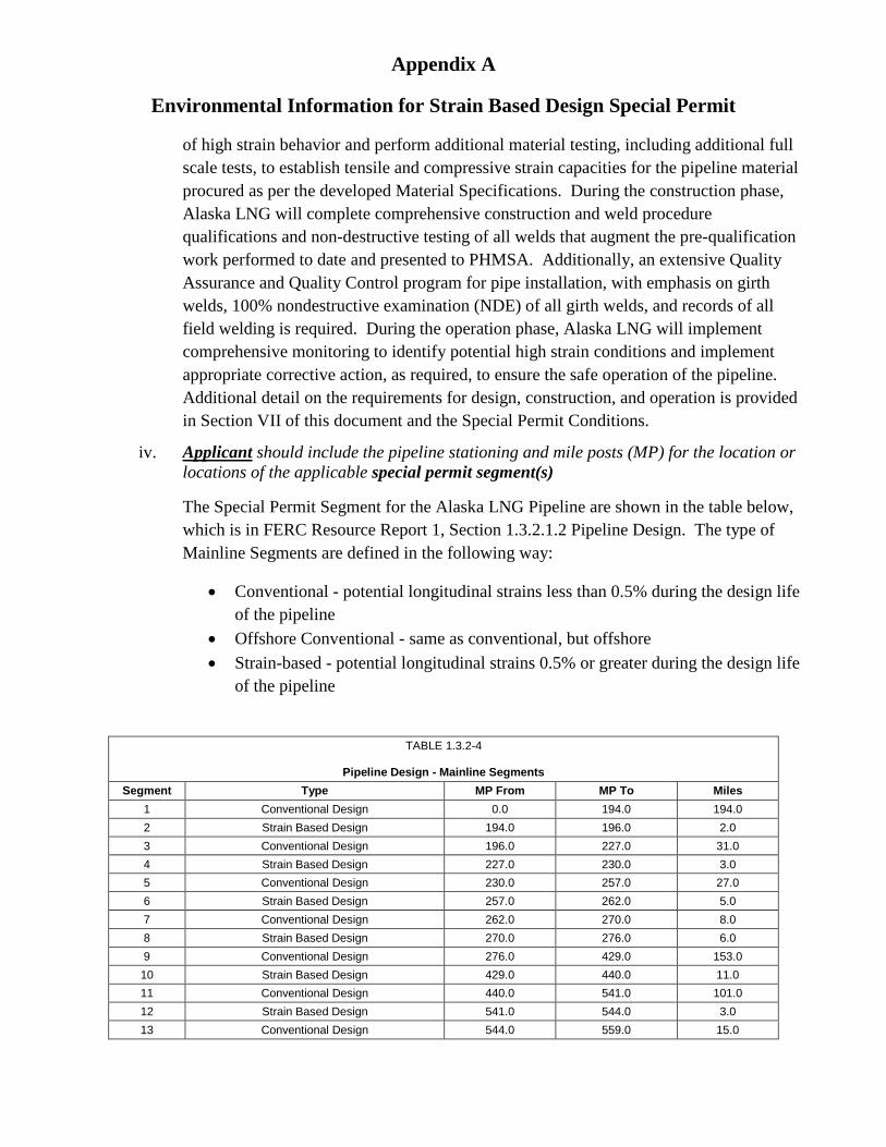
iv. Applicant should include the pipeline stationing and mile posts (MP) for the location or locations of the applicable special permit segment(s)
The Special Permit Segment for the Alaska LNG Pipeline are shown in the table below, which is in FERC Resource Report 1, Section 1.3.2.1.2 Pipeline Design. The type of Mainline Segments are defined in the following way:
• Conventional - potential longitudinal strains less than 0.5% during the design life of the pipeline
• Offshore Conventional - same as conventional, but offshore • Strain-based - potential longitudinal strains 0.5% or greater during the design life
of the pipeline
TABLE 1.3.2-4
Pipeline Design - Mainline Segments Segment Type MP From MP To Miles
Additional mitigation measures are addressed in Section VII of this document and the Special Permit Conditions.
IV. Environmental Impacts of Proposed Action and Alternatives a. Describe how a small and large leak/rupture to the pipeline could impact safety and the
environment/human health. The following consideration of the potential impacts of small and large pipelines leaks/ruptures to the environment, and human health, apply equally to the proposed action and primary no-action alternatives, given that they both have a below-ground design basis.
i. Any discussion of the consequence of a leak or rupture must be put into the context of its probability. For the following reasons, it is highly unlikely that a leak or rupture occurring in the SBD segments will impact the environment or human health:
a) Remoteness of the pipeline route. More than 99% of the Mainline route is in Class 1 location (801.0 miles of 806.6 miles). The frequency of incidents is significantly less for pipelines in Class 1 locations than in Class 2, 3 or 4 [see Table 3. in Eiber 20001].
b) Resilience to third party mechanical damage - Given the remoteness of the pipeline and the high thickness of the pipeline, there is very low risk of mechanical damage. However, fracture mechanics calculations have shown that the SBD pipe is very resistant to fracture, capable of withstanding a through wall thickness puncture of greater than 7” in length without rupturing. If rupture did occur, the SBD pipe will be designed to prevent a propagating fracture in accordance with the requirements of 49 CFR § 192.112.
c) Very low probability of corrosion damage -The Mainline will be transporting a dry, LNG specification gas, which contains no significant quantities of the species required to cause corrosion: water (<0.1 lbs/MMSCF), CO2 (<50 ppmv) and H2S
1 Eiber, R., McGehee, W., Hopkins, P., Smith, T., Diggory, I., Goodfellow, G., Baldwin, T. R. and McHugh, D. 2000. Valve Spacing Basis for Gas Transmission Pipelines. Pipeline Research Council International, PRCI Report PR 249 9728. January.
Appendix A
Environmental Information for Strain Based Design Special Permit
(≤4 ppmv). With these low impurity contents, a corrosive liquid water phase will not form inside the pipeline. Therefore, the probability of internal corrosion is minimal. To ensure the integrity of the pipeline, the in line inspection program will comply with the robust requirements of 49 CFR § 192.620. External corrosion will be mitigated by using a high integrity coating with a cathodic protection system.
d) Compliance with Alternative MAOP requirements - The entire Mainline will be operated and maintained per 49 CFR § 192.620, which establishes the most rigorous operational requirements in 49 CFR 192. Additionally, more than 615 miles of the total Mainline length, to include Alternative MAOP and SBD segments, will also comply with 49 CFR §§ 192.112 and 192.328, which establish the most rigorous design and construction requirements, respectively, in 49 CFR 192.
ii. A small leak from a buried pipeline would result in a gradual release of gas, with the total amount of gas being released dependent on the time it takes for the leak to be detected and fixed. Small leaks would primarily be identified through mass balance systems incorporated in gas pipeline control. Gas from a small leak would permeate through the backfill material (soil) before dissipating into the air. Small pipeline leaks may result in some impacts to, or loss of, surrounding vegetation. This localized browning of vegetation can facilitate identification of small underground leaks during right of way inspection, which will be performed at intervals not exceeding 45 days, but a least 12 times each calendar year (per 49 CFR § 192.620(d)(4)). Other visual techniques are available including inspection of snow pack (seasonal).
iii. A rupture would result in the rapid release of a large volume of natural gas resulting in significant damage to the pipeline and would create a trench or crater in the immediate vicinity of the rupture. If an ignition source is present, an intense fire or explosion would result. The extent of the damage due to the fire caused from a rupture would depend on the extent of the combustible materials in the vicinity of the rupture, and local environmental conditions. The probability for personnel injury and property damage is relatively small for this largely remote pipeline and decreases as distance from the rupture increases. As the pipeline will be sectionalized with mainline block valves, the gas released during a rupture scenario would be limited to the inventory between valves. The spacing between the block valves is the subject of a Transmission Line Valve Spacing Special Permit. This Special Permit includes automatic shut-off valves and remote controlled valves for line break detection and automatic valve closure. Large ruptures would be easily detectable through monitoring of pressure and flow conditions at pipeline facilities.
b. Submit an explanation of delta/difference in safety and possible effects to the environment between the 49 CFR Part 192 baseline (Code baseline) and usage of the special permit conditions for strain based design mitigation measures.
Appendix A
Environmental Information for Strain Based Design Special Permit
i. For the purposes of this assessment, Alaska LNG assumes that the No Action alternative and the Proposed Action alternative would both be below-ground design, with the exception of the noted above-ground segments at water crossings and faults – these aboveground segments would be unchanged under the No Action and Proposed Action alternatives.
The anticipated differences in effects for individual resources between the No Action alternative and the Proposed Action alternative are discussed below. The differences are generally negligible because both alternatives are premised on below-ground design and installation. The environmental impact and mitigation considerations for buried pipelines are listed here in summary form.
• Visual impacts would be limited to the linear cleared corridor (apart from above-ground sections at select water and fault crossings). Revegetation similar to adjacent vegetation types would be promoted in disturbed areas outside of the permanent ROW. Vegetation type and density within the permanent ROW would be subject to pipeline integrity and inspection requirements.
• Smaller footprint required for associated aboveground facilities.
• Construction ROW wider due to need for excavation safety requirements and for storage of trench spoil material during construction
• More initial wetland impacts due to trenching, but partially offset by restoration efforts to facilitate wetlands restoration where permanent fill is not required
• The route has soil types that have a high susceptibility to erosion, which could occur as a result of both the ROW regrading and ditching. The Alaska LNG Upland Erosion Control, Revegetation and Maintenance Plan, Winter & Permafrost Construction Plan and Restoration Plan will provide mitigation strategies to reduce the potential for erosion and sedimentation.
• The potential for aufeis formation in stream crossings would be mitigated by both the operating procedures and Project design documents.
• The Project would have design, construction and operating procedures/ practices that would implement permafrost Best Management Practices (BMPs) to reduce impacts the pipeline ditching, backfill, and construction would have on the permafrost.
• No above-ground obstructions allows for continued free passage of wildlife
• No barriers to all-terrain vehicles or snow machine traffic, where authorized on the ROW.
Appendix A
Environmental Information for Strain Based Design Special Permit
FERC RR 10 (Section 10.4.5.1) contains a detailed comparative analysis of above-ground and below-ground design alternatives. Further detailed information and analysis of the environmental impacts of a buried pipeline are contained in the FERC Resource Reports and are referenced accordingly, where applicable in the following analyses of the difference in environmental impacts between the Project action and no-action alternatives. The basis for the FERC Resource Reports is the Proposed Action Alternative. However, the associated environmental impact analysis is also applicable to the No Action alternative, given both alternatives are based on below ground design and installation, and both follow an identical route.
1. Human Health and Safety
Given that both alternatives have a below ground design basis, there is negligible difference in human health and safety impacts between the No Action and Proposed Action alternatives. A buried pipeline has the advantage of being less likely to be damaged by:
• Heavy equipment being transported cross country, especially under winter whiteout conditions;
• Intentional or unintentional bullet strikes such as happened to the Trans-Alaska Pipeline in 20012;
Avalanches in the high narrow valleys of the Alaska Range Crossing The pipeline route through the permafrost areas is extremely remote, with human use consisting primarily of subsistence and recreational hunting and related activities. As such, the potential for people to be impacted by a gas release and potential subsequent explosion and fire is low.
Pipeline design and operational safety is covered in detail in FERC Resource Report 11 (Reliability and Safety).
2. Air Quality
There would be no significant difference in emissions between the No Action and Proposed Action alternatives. The majority of heavy equipment required for construction in either alternative will be the same, including equipment such as brushers and bulldozers for the clearing and leveling of the ROW, trucks for transporting pipe, and sidebooms and welding trucks for pipe placement and welding. Increases in the haul loads of the heavier pipe during construction, and increased time for welding of the thicker pipe during construction, would be required for the No-Action alternative although this is not likely to significantly increase overall emissions. O&M activities to
Environmental Information for Strain Based Design Special Permit
maintain the pipeline for the No Action and Proposed Action alternatives would require similar equipment and personnel.
Detailed description of air emissions from pipeline construction and operations are contained in FERC Resource Report 9 (Air and Noise Quality).
3. Aesthetics
There would be no difference in visual effects between the No Action and Proposed Action alternatives. Visual effects from both would be limited to the ROW clearance, which would be less obvious with winter snow cover.
Analysis of potential impacts to aesthetics, and associated mitigations, from a below ground pipeline are considered in FERC Resource Report 8 (Land Use, Recreation and Aesthetics).
4. Biological Resources (including vegetation, wetlands, and wildlife).
There would be no difference in impacts to vegetation, wetlands and wildlife between the between the No Action and Proposed Action alternatives. Both alternatives will be below ground and follow the same route.
FERC Resource Report 3, (Fish, Wildlife and Vegetation), contains descriptions of vegetation and wildlife resources, and potential impacts associated with the Mainline route. FERC Resource Report 2 contains a detailed analysis of wetlands affected by the Mainline route, and mitigation of impacts.
5. Climate Change
There would be no difference in emissions of greenhouse gases between the No Action and Proposed Action alternatives. The No Action and Proposed Action alternatives would both require activity by fossil fuel-burning equipment for ground clearance, transportation of construction materials and employees, and stringing of the pipeline itself.
FERC Resource Report 9 (Air and Noise Quality) discusses Greenhouse gas emissions from the Project.
6. Cultural Resources
There would be no difference in the effect on Cultural Resources between the No Action and Proposed Action Alternatives. Construction activities have the potential to affect cultural resources. Ground-clearing activities under both cases would be similar. FERC is conducting the Section 106 consultation process with stakeholders. This process will lead to the development of a Programmatic Agreement that would address management
Appendix A
Environmental Information for Strain Based Design Special Permit
and recovery of known cultural resources, as well as any discovered during project implementation. The Programmatic Agreement would apply to both the No Action and Proposed Action alternatives to mitigate effects on these resources. FERC Resource Report 6, (Cultural Resources), addresses cultural resources affected by the Project, and associated mitigations.
7. Environmental Justice
Since both pipeline designs would be sited in the same footprint, there would be no difference in effects on the environment resulting from construction or operation of the pipeline between the No Action and Proposed Action alternatives.
8. Geology, Soils and Mineral Resources
There would be minimal difference in the effect on Geology, Soils, and Mineral Resources between the No Action and Proposed Action Alternatives. Construction activities have the potential to affect soils in a localized manner, with minimal effect on regional geology or mineral resources. Construction activities that could contribute to erosion include clearing and grading, excavation trenching, stockpile management, backfilling, and the development of gravel pads. Most erosion effects are effectively managed through the use of erosion and sediment control measures, including:
• The use of winter construction in areas of inundated and frozen ground conditions;
• Use of settlement basins, silt fences, and other Best Management Practices (BMP) for storm water control;
• Use of engineered flow diversions and slope breakers to control water flow on slopes and around water courses; and
• Installation of trench breakers to address storm and groundwater flow through the trench backfill or during construction.
Operations and maintenance activities along the pipeline right-of-way, performed to meet 49 CFR Part 192 would be similar for the No Action and Proposed Action alternatives. All O&M excavations would be conducted as authorized under the applicable ROW authorization. As the land management agencies responsible for lands along the pipeline route, ROWs would be issued by one, or both, of the Bureau of Land Management and Alaska Department of Natural Resources. All excavations and other applicable activities would be permitted through the appropriate Federal and State agencies for both of these alternatives. Both alternatives would have similar impacts on soil resources.
Appendix A
Environmental Information for Strain Based Design Special Permit
FERC Resource Report 7 (Soils), contains a more detailed discussion of impacts to soils and erosion resulting from the pipeline construction and the potential mitigation measures to address those impacts. FERC also has a standard Upland Erosion Control, Revegetation and Maintenance Plan, to which the Alaska LNG Project has proposed alternative measures that will be subject to FERC approval.
9. Indian Trust Assets
No Indian Trust Assets or Native allotments are located within the pipeline route.
10. Land Use, Subsistence, and Recreation
There would be no difference in the effect on Land Use, Subsistence, and Recreation between the No Action and Proposed Action Alternatives. During construction, land use in the form of subsistence activities and recreation for both alternatives could be altered in the immediate vicinity of activities. The pipeline’s remote location, combined with the relatively small width of the ROW, would generally limit the extent of displacement by users to the active construction zones. Construction activities would be timed to avoid potential use conflicts with the portions of the trail used during the annual Iditarod sled-dog race.
After construction the ROW would be graded and revegetated to a stable condition in accordance with the FERC approved Alaska LNG Upland Erosion Control, Revegetation and Maintenance Plan; Alaska LNG Wetland & Waterbody Construction & Mitigation Procedures; and the associated Alaska LNG Project Restoration Plan . No long term linear access along the pipeline alignment is proposed. However, under either alternative, PHMSA regulations will require that the pipeline ROW is brushed to prevent the growth of large vegetation over and around the pipeline to maintain a clearly defined ROW.
FERC Resource Report 8 (Land Use, Recreation and Aesthetics) considers potential effects to land use and recreation activities. FERC Resource Report 5 (Socioeconomics) considers potential impacts to subsistence.
11. Noise
There would be no difference in Noise Impacts between the No Action and Proposed Action Alternatives. Impacts would generally be limited to the sounds of construction equipment operations. Human use of the area is transient and limited, resulting in a relatively short duration of effect (transiting the area). Wildlife could also be affected by construction-related noise. Noise related to operation of the pipeline itself would primarily result from operation of compressor and heater stations and periodic ROW maintenance and inspection activities. Compression requirements are the same for both
Appendix A
Environmental Information for Strain Based Design Special Permit
alternatives, so there is no change to the number of compressor and heater stations and the associated noise profile.
FERC Resource Report 9 (Air and Noise Quality) contains a detailed discussion of noise impacts associated with pipeline construction and operation.
12. Water Resources
There would be no difference in impacts to water resources between the No Action and the Proposed Action Alternatives. For both alternatives, stabilization techniques, including gravel blankets, riprap, gabions, or geosynthetics, would be used to stabilize the channel bed and stream banks at stream crossings. The majority of rivers and streams along the pipeline route would be crossed by an open-cut method during winter months; during these months the flows of rivers and streams are lowest, and disturbance of the channel and stream bank can be minimized. Burial depths for crossings have been based on site specific calculations to avoid the potential for scour. Watercourse crossing methods for each watercourse crossing are the same for both alternatives.
FERC Resource Report 2 (Water Use and Quality) contains a detailed discussion regarding the management of water during construction and operation of the pipeline, as well as impacts to ground, surface water flow, and quality resulting from the construction and operation of the pipeline.
c. Describe safety protections provided by the special permit conditions.
i. What factors were considered to ensure the conditions are adequate to protect against waiving protections, (maximum pipe strength limitations), of the code.
Once the potential for settlement and heave have been quantified, an appropriate pipe grade and wall thickness must be selected to safely withstand the longitudinal strain that may result. Specific test work requirements for the selection and production of the pipe will be established to ensure that the steel is of appropriate quality. Specific training, monitoring and testing requirements will be established for welding during construction. Specific requirements for monitoring through operations will be established to ensure that any longitudinal strains that exceed those contemplated in the design are identified and mitigated in a timely manner. These are discussed in more detail in Section VII.
Over the full operational life of the pipeline the Special Permit will require extensive evaluation of the potential for time dependent ground movement, such as thaw settlement and frost heave.
ii. What are the safety and environmental risks from usage of strain based design that need to be protected against?
Appendix A
Environmental Information for Strain Based Design Special Permit
The safety and environmental risks associated with the Proposed Action would result from change to permafrost and wetland conditions, leading to a leak or rupture of the pipeline and the subsequent release of gas and possible explosion or fire. The use of SBD as outlined in the Special Permit will ensure that the pipeline is designed, constructed, maintained, and operated in a way that avoids failure. Fracture mechanics calculations have shown that the SBD pipe is very resistant to fracture, capable of withstanding a through wall thickness puncture of greater than 7” in length without rupturing. If rupture did occur, the SBD pipe will be designed to prevent a propagating fracture in accordance with the requirements of 49 CFR § 192.112.
d. Explain the basis for the particular set of alternative mitigation measures used in the special permit conditions. Explain whether the measures will ensure that a level of safety and environmental protection equivalent to compliance with existing regulations is maintained.
The basis for the mitigation measures is the expectation that some segments of the pipeline may experience thaw settlement or frost heave after construction, resulting in longitudinal strain on the pipe that exceeds 0.5%. To address this expectation, the mitigation measures require the quantification of the maximum amount of thaw settlement and frost heave possible, the selection of an appropriate pipe grade and wall thickness, use of steel of an appropriate quality, and ongoing O&M procedures to deal with increases of the pipeline longitudinal strain. Additional welding procedure and welder qualification, as well as enhanced welding quality during construction, will be employed to ensure sufficient weld strength to deal with the longitudinal strain. Monitoring requirements during operation are established to ensure that the longitudinal strain does not exceed that contemplated in design, while mitigation requirements are established in the event that does happen.
The use of the above measures helps to ensure that no significant environmental impact will result from the use of SBD. Rather, it is anticipated that fewer pipeline remediation activities will be required during the design life, thereby reducing the future disturbance of the pipeline route during operation.
e. Discuss how the special permit would affect the risk or consequences of a pipeline leak, rupture, or failure (positive, negative, or none). This would include how the special permits preventative and mitigation measures (conditions), would affect the consequences and socioeconomic impacts of a pipeline leak, rupture, or failure.
The Special Permit will allow for burial of the pipeline in areas that may be susceptible to high magnitudes of thaw settlement or frost heave, which could lead to increased longitudinal strain on the pipeline and ultimately failure if appropriate mitigation is not in place. The conditions imposed by the Special Permit result in a pipeline that is designed, constructed, and operated in such a way that thaw settlement and frost heave will not lead to pipeline failure. The
Appendix A
Environmental Information for Strain Based Design Special Permit
consequences of a pipeline failure would be similar under either the Proposed Action or the No Action alternative.
f. Discuss any effects on pipeline longevity and reliability such as life-cycle and periodic maintenance including integrity management. Discuss any technical innovations as well.
Full implementation of the conditions in the Special Permit will ensure that there are no overall impacts on pipeline longevity and reliability. Implementation of the conditions will impose additional requirements for pipeline integrity management, monitoring, and periodic maintenance.
Requirements for design include:
• The development of an overall SBD Plan that addresses all aspects of the pipeline’s life cycle including design, materials, construction, and operations and maintenance (O&M);
• Comprehensive material testing of the pipe, and welds, to include both small scale and full scale compression and tension tests;
• The development and implementation of written material, design, construction, and O&M specifications and procedures; and
• Engineering critical assessments.
Requirements for construction include:
• Expanded welding procedure and welder qualification requirements; • Expanded testing requirements for welds; • Running a high resolution deformation tool through all SBD segments; • Expanded grounding and cathodic protection requirements; and • Development of a ROW monitoring program.
Requirements for O&M include:
• Development of O&M procedures for all operating parameters that have an effect on compliance with the Special Permit;
• Monitoring and determination of pipeline strain demand and specified timelines for remediation;
• Remedial action for coating disbondment; • Interference current control; • Integration and analysis of integrity data; and • Expanded requirements for the reporting and certification including both technical; and
management oversight.
g. Discuss how the special permit would impact human safety.
Appendix A
Environmental Information for Strain Based Design Special Permit
The Special Permit should improve human safety by allowing for burial of the pipeline in permafrost areas without pipeline failure resulting from thaw settlement or frost heave. Burial of the pipeline reduces the potential for pipeline failure resulting from human actions or other natural causes, thereby reducing the overall likelihood of failure and the potential for injury from the resulting release of gas.
h. Discuss whether the special permit would affect land use planning.
By allowing for burial of the pipeline, the Special Permit should provide for flexibility in land use planning. Burial will reduce visual impacts associated with the line and reduce the potential for human caused damage to the pipeline.
i. Discuss any pipeline facility, public infrastructure, safety impacts and/or environmental impacts associated with implementing the special permit. In particular, discuss how any environmentally sensitive areas could be impacted.
Implementation of the Special Permit will not affect any pipeline facilities, public infrastructure, or environmentally sensitive areas.
V. Consultation and Coordination
a. Please list the name, title and company of any person involved in the preparation of this document.
Preparers: Alaska LNG LLC – Rick Noecker (PHMSA Filing Coordinator), Mario Macia (Pipeline Technology Lead), Patrick McAlister (Pipeline Design Lead), Norm Scott (ERL Advisor); Michael Baker International – Keith Meyer (Senior Pipeline Advisor)
b. Please provide names and contact information for any person or entity you know will be impacted by the special permit. PHMSA may perform appropriate public scoping. The applicant’s assistance in identifying these parties will speed the process considerably.
Cook Inlet Region, Inc. Jason Brune Sr. Director, Land and Resources PO Box 93330 Anchorage AK 99509 (907) 263-5104 Bureau of Land Management Earle Williams Chief, Branch of realty and Conveyance Services BLM Alaska State Office222 W. 7th Avenue #13 Anchorage
Appendix A
Environmental Information for Strain Based Design Special Permit
AK 99513-7504 (907) 271-5762 Alaska Department of Natural Resources Jason Walsh State Pipeline Coordinator 3651 Penland Parkway Anchorage AK 99508 (907) 269-6419 Alaska Dept. of Transportation & Public Facilities David T Bloom Gasline Liaison 2301 Peger Road Fairbanks AK 99709 (907) 451-5497
c. If you have engaged in any stakeholder or public communication regarding this request, please include information regarding this contact.
Alaska LNG has been active in stakeholder engagement throughout Alaska. As well, Federal, State, and Local agency engagement is ongoing. In 2015 and 2016, Alaska LNG held one-on-one as well as multiagency engagement meetings to cover pipeline design construction and routing. Included in the multiagency meetings were presentations and discussions related to permafrost management from pipeline construction and operation.
PHMSA has participated in scoping and public outreach lead by FERC related to the Alaska LNG FERC Resource Reports. Details of the public outreach, which included both members of tribal entities and the general public, are provided in Sections 1.9 and 5.1 of the FERC Resource Reports.
VI. Bibliography Applicant to document information submitted, if they consulted a book, website, or other document to answer the question, please provide a citation. See footnote.
VII. Conditions: Example of what special permit (SP) conditions address
Appendix A
Environmental Information for Strain Based Design Special Permit
a. If Applicant plans to use strain based design, detail the use of strain based design and the procedures/conditions to be included in a special permit application to address frost heave, thaw settlement, and other geotechnical issues associated with the arctic or sub-arctic.
Alaska LNG proposes to use SBD to specifically address thaw settlement and frost heave as discussed in Section II, and will apply to PHMSA for a Special Permit as described in Section III (b) (i). To accommodate Alaska LNG’s request, PHMSA identified the series of Special Permit conditions described below.
b. The special permit submittal should explain how Applicant will develop and monitor strain based design from a quality assurance standpoint as follows:
1. Materials – specifications for steel strength, pipe dimensions pipe toughness, steel strength, qualification and manufacturing tests, and steel and pipe mill quality inspections.
a. What Regulatory Code and industry standards will be used for steel and pipe qualifications?
The Alaska LNG pipeline in SBD segments will be constructed of line pipe meeting the requirements of API 5L, Grade X70M, PSL2, and will comply with the additional design requirements for steel pipe using alternative MAOP as given in 49 CFR § 192.112. In addition, Alaska LNG will develop a pipe material specification to ensure consistent material properties are used for material testing, strain capacity modeling, welding procedures, and strain demand limits. The Pipe Material Specification for use in SBD segments will include the requirements contained in Attachment A to the Special Permit Conditions.
b. Will Applicant conduct a small scale and full scale testing program for steel, pipe, girth welds, and anomalies (such as corrosion anomalies) to determine tensile strain capacity or limits?
Alaska LNG will conduct small-scale and full-scale tests on line pipe and welds representative of those that will be used to construct the pipeline. The full-scale tests will be used to confirm the validity of strain capacity models. Test results in combination with the models will be used to determine strain capacity limits. The strain capacity limits will consider the variations of pipes and girth welds for expected production pipe, double jointing welds, field welds, tie-in welds and repair welds.
Strain capacity of pipe with anomalies, such as corrosion anomalies, will be evaluated using finite element analysis, a numerical method used to model pipe structural behavior with a computer. The models considering corrosion anomalies will be validated with full-scale tests.
c. What design safety factor will be used for test program results?
Appendix A
Environmental Information for Strain Based Design Special Permit
The safety factor for the tensile strain demand limit is 1.667: i.e., the tensile strain demand limit is the tensile strain capacity calculated using the procedures described by Tang, et al., divided by the dimensionless safety factor of 1.667.
The safety factor for the compressive strain demand limit is 1.25. However, a safety factor of 1.11 may be used for Class 1 locations that (a) are not in the right-of-way for an aboveground pipeline, (b) are not in the right-of-way for a designated interstate, freeway, expressway, or other principal 4-lane arterial roadway, or (c) contain less than two buildings within a potential impact circle (as defined in § 192.903), that have human occupancy of more than 50 days in a 12-month period. The compressive strain demand limit is the compressive strain capacity calculated using project-specific compressive strain capacity models, which are based on finite element analysis, divided by the compressive strain capacity safety factor. The test program results will be used to validate the compressive strain capacity model. Alaska LNG may propose an alternate safety factor, in which case, the proposed safety factor shall be reviewed by an independent third party and PHMSA. Alaska LNG will implement the alternate safety factor only if no objection is received from PHMSA.
d. What will be the test sample size?
The final test sample sizes are not yet established. To date, 10 full-scale tension tests and 10 full-scale bend tests have been performed on NPS42 sample pipes. Full-scale tension tests consist of two or more pipe pieces welded together pulled in tension. Internal pressure is typically applied to the specimen, and the welds may contain intentionally introduced flaws and high-low misalignment. Similarly, full scale bend tests are performed on internally pressurized pipe, with or without a girth weld and associated flaws and high-low misalignment. The tests performed to date have been reviewed by DNV GL, acting in the capacity of independent third party reviewer, and confirm the suitability of the tensile and compressive strain capacity models performed by Alaska LNG. Additional tests may be performed in the future to evaluate repair welds, additional pipe manufacturers, anomalies or an alternate pipe diameter, if the design of the pipeline changes.
Additionally, comprehensive small-scale testing has been performed on NPS42 pipe samples produced by three manufacturers and on mechanized mainline welds and tie-in welds. Additional testing may be performed to evaluate additional pipe manufacturers and welding procedures. In addition, before final production of project line pipe, the selected manufacturer will perform manufacturing procedure qualification tests as required by Appendix A of the Special Permit. Conditions and project weld procedures will be subject to full weld qualification testing to the requirements of API 1104 and project specifications.
As required by Condition 3 of the Permit Conditions, Additional details on test sample size will be submitted to PHMSA and an independent third party reviewer as part of Element 1 of Alaska LNG’s Strain Based Design Plan.
e. What tests will be conducted during manufacturing?
Appendix A
Environmental Information for Strain Based Design Special Permit
The tests required during pipe manufacturing are presented in Appendix A, Table A-3 of the Special Permit Conditions (reproduced below).
Appendix A
Environmental Information for Strain Based Design Special Permit
Special Permit Appendix A, Table A-3: Test and Requirements
Items Frequency NOTE 3 Number, location and
orientation of specimen (See Note 4)
Pipe BodyNOTE 1
Chemical composition product analysis 1/heat 1
Pipe body transverse tensile 1/lot NOTE 2 1 Pipe body longitudinal tensile
(aged) 1/lot 1 (90°, longitudinal)
Charpy impact - pipe body transverse 1 set of 3 specimens 1 set of 3 specimens
DWTT 2 2
Weld
Welded joint tensile 1 1 Guided root bending 1 1 Guided face bending 1 1 Charpy impact - weld 1 set of 3 specimens 1 set of 3 specimens Charpy impact - HAZ 1 set of 3 specimens 1 set of 3 specimens
Macro 1 1 Vickers hardness Per API 5L Per API 5L
Hydrostatic pressure test Each pipe Visual Each pipe
Dimension Each pipe NDT Each pipe
NOTE 1: For helical seam pipe the samples must be taken mid-way between the weld seam. NOTE 2: A lot is defined as 100 pipes, or per heat, or as per API 5L, whichever is less. NOTE 3: Testing frequency and test type must meet both Table A-3 and API 5L criteria. NOTE 4: Location and orientation must comply with API 5L, if not specified otherwise.
f. How often will tests during manufacturing be conducted – per heat3? i. Testing frequencies for each test are outlined in Appendix A, Table A-3 of the Special
Permit Conditions (see table above). ii. In addition, manufacturing procedure qualification tests will be conducted on pipe from
two heats of steel as follows:
Two pipes per heat will be tested for:
1. Chemical analysis;
2. Longitudinal and hoop tensile tests in the as-received condition;
3 Typical heat sizes used by steel mills will result in 35-45 Alaska LNG Mainline pipes
Appendix A
Environmental Information for Strain Based Design Special Permit
3. Longitudinal tensile tests of pipe body in the aged condition;
4. Longitudinal compression tests of pipe body in the aged condition;
5. Tensile Test of seam weld in the as-received condition;
6. Charpy impact test (pipe body transverse, weld and HAZ), at the specified temperature;
7. DWTT, at the specified temperature;
8. Vickers Hardness traverse across seam weld;
9. Guided bend test; and
One (1) pipe from each heat will be tested as follows:
1. Metallography of pipe body;
2. Visual inspection and dimensions;
3. Nondestructive inspection;
4. Hydrostatic test at an applied hoop stress corresponding to 100% SMYS;
5. Single Edge Notch Tension (SENT) tests or Crack Tip Opening Displacement
(CTOD) tests of pipe body to measure tearing resistance curves;
6. For information only, Charpy transition curve of the pipe body in the aged condition, as determined via the Charpy V-Notch (CVN) impact test
2. Material Test Program – What types of small scale and full scale testing, design and material specifications qualifications are needed for the project including girth welds and anomaly effects?
Small-scale tests of pipe will consist of those listed in VII(1)e for production testing and VII(1) f for manufacturing procedure qualification testing. Small-scale tests of girth welds will consist of the test required for weld procedure qualification according to American Petroleum Institute (API) Standard 1104, Welding of Pipelines and Related Facilities in addition to the following supplemental tests:
1. All weld metal tensile tests; 2. CTOD; 3. SENT tests.
Full-scale tests to assess compressive strain capacity will consist of pressurized bend tests and will include plain pipe tests, tests of pipes with girth welds with a range of high-low misalignment, and tests of pipes with cold bends (i.e. field bends).
Full-scale tests to assess tensile strain capacity will consist of pressurized tension tests including girth welds with flaws and high-low misalignment.
Appendix A
Environmental Information for Strain Based Design Special Permit
Project-specific line pipe material and girth weld specifications specify the type and number of small-scale tests required to qualify the pipe manufacturing procedure(s) and girth welding procedures.
The Alaska LNG design approach for strain capacity will be qualified by confirming the applicability of tensile and compressive strain capacity models with full-scale tests on sample materials procured to Alaska LNG specifications. Similarly, finite element models addressing the effects of anomalies on strain capacity will be validated with full-scale tests.
a. How will the remaining wall strength calculations be validated?
Because the Alaska LNG pipeline will utilize high integrity corrosion coatings and utilize a cathodic protection system that complies with Condition 13 of the Special Permit Conditions, it is anticipated that wall loss anomalies will be infrequent on this pipeline. Similarly, even within the special permit segments, the length of pipeline that is expected to experience strains over 0.5% is anticipated to be limited. Therefore, the overlap of strain and a wall loss anomaly is anticipated to be a rare event. For the majority of cases where wall loss anomalies are detected and strain is not present, remaining wall strength calculations will be performed according to ASME/ANSI B31G, in compliance with 49 CFR §192.485. In the unlikely event that wall loss anomalies occur in a location with longitudinal strains that exceed 0.5%, the effect of strain on remaining strength will be accounted for using procedures approved by PHMSA in accord with the Special Permit Conditions. O&M procedures for remaining wall strength calculations accounting for strain will be developed based on results of the material testing program, finite element analysis of the anomaly, and available PHMSA research on the effects of anomaly wall loss under combined pipeline loadings. Should PHMSA research indicate additional tests are required for the effects of anomalies, Alaska LNG will provide the required tests, finite element analysis, and O&M procedures for the special permit segments.
b. How will steel and girth weld strength variability be accounted for in the design? i. Design calculations will be performed for a range of steel and girth weld strengths using
the results of the project material testing program; ii. During operations, site specific assessments of strain capacity will be based on the best
known information on the pipe and weld strength for the location where strain is occurring. Information sources that will be utilized will include the pipe production data for the specific pipe manufacturer and weld qualification data for the type of weld experiencing strain. Where a range of data is available, conservative selections will be used as input to the tensile and compressive strain capacity models.
3. Geotechnical Test Program
A project-specific geotechnical test program has been conducted to characterize the subsurface route conditions. Additionally, geotechnical results from other Alaskan geotechnical field programs that share a similar route have also been collated into the project Geographic Information System (GIS). These additional field programs include
Appendix A
Environmental Information for Strain Based Design Special Permit
those conducted by Trans-Alaska Pipeline System (TAPS), the Alaska Natural Gas Transportation System (ANGTS), the Alaska Pipeline Project (APP), and the Alaska Stand Alone Pipeline (ASAP). Collectively, these results have been used to quantify the magnitude and extents of frost heave and thaw settlement geohazards and to estimate the resultant strain demand.
a. Where and how many geotechnical tests will be conducted? Over 9,000 geotechnical investigation locations comprising approximately 38,000 laboratory tests have been conducted.
• ASAP – 1,883 boreholes and 4,445 laboratory tests available to Alaska LNG which includes borehole data from the Alaska Department of Transportation and Public Facilities (DOTPF);
• In addition, the project is utilizing publically available ANGTS geotechnical alignment sheets that include the soil types and landform types with depth along the alignment based on borehole data, water table depths, and terrain units, among other information.
It is noted that ASAP, TAPS, APP and ANGTS utilized similar routing north of Fairbanks.
Additionally, geotechnical characterization along the route included Light Detection and Ranging (LiDAR), aerial photography, seismic trenching, and terrain unit mapping.
b. What are engineering parameters for tests? The main engineering parameters related to the tests include Unified Soil Classification, dry density, moisture content, and thermal state (during borehole logging).
c. What are examples of how pipe will be designed: above ground, heavier wall thickness, or maximum strain?
As described in Section III above – Alternative installation modes to the base case of burial of the X80 grade line-pipe, which follow the Alternative MAOP provisions of 49 CFR 192 could include the following installation modes: buried heavier wall thickness pipe, removal and replacement of frost heave/thaw unstable materials, trenchless technologies, soil stabilization using measures such as thermosyphons, or a combination of these methods.
Appendix A
Environmental Information for Strain Based Design Special Permit
The Proposed Alternative will be designed using strain based design techniques allowing the pipe to experience strains beyond 0.5%, but with strains limited to specified percentages of the material strain capacity established based on actual material testing. The target values of the material strain capacities are based on the engineering assessment of the magnitude of pipe displacements due to ditch heave or thaw settlement along the alignment, using the soil index values from the samples recovered from the field geotechnical investigations.
4. Design and Construction – design procedures, specifications, design factors, and inspection including pipe and weld misalignment.
a. What are the temperature effects on strain based design loads and tensile strain capacity? i. The temperature differential that the pipeline material experiences, due to the difference
between the temperatures of the subsurface at construction tie-in to the operating temperature of the product, causes a mechanical stress (strain) that all pipelines routinely account for in design calculations, and which Alaska LNG includes in all pipeline strain determinations along the route. To illustrate the magnitude of this added strain, an example is: for a tie-in temperature at -10 degrees Fahrenheit and for a maximum operating temperature of 80 degrees Fahrenheit, the temperature difference of 90 degrees Fahrenheit from the tie-in temperature to the operating temperature results in an added strain magnitude of about 0.06%.
ii. The effects of ground surface disturbance on the ROW, operating pipeline temperature, and climate after construction may cause thaw of permafrost below the pipe, largely due to the increase of heat energy entering the ground from the construction disturbance on the ROW. Consolidation of the thawed soils may in turn cause an overall decrease in soil volume and settlement of the pipe ditch bottom. The magnitude of the thaw depth beneath the pipe, along with the associated settlement of the soil within this thaw depth depends on the geomechanical and geothermal properties of the subsurface, which in turn depend on the properties of the subsurface found from the geotechnical field investigations as discussed in Response #3 above. The Alaska LNG FERC Resource Reports discuss ditch displacement and notes that the designs and measures, best management practices, and erosion and sediment control measures are expected to reduce permafrost impacts during construction and operation.
iii. The effect of the climate and pipeline operating temperature on the subsurface below the
pipe after construction may cause freezing of unfrozen soil beneath the pipe, largely due to the effects of the chilled pipeline. Freezing of the subsurface soils may in turn cause water migration to the frost front and resultant upward displacement of the pipe ditch bottom. The magnitude of associated heave of the soil within the frozen bulb of soil
Appendix A
Environmental Information for Strain Based Design Special Permit
around the pipe depends on the geomechanical and geothermal properties of the subsurface, which in turn depends on the properties of the subsurface found from the geotechnical field investigations as discussed in Response #3 above. The Alaska LNG FERC RRs discuss ditch displacement and notes that the designs and measures, best management practices, and erosion and sediment control measures are expected to reduce frost heave impacts during construction and operation. Temperature does not affect the tensile strain capacity based on the predictive equations for tensile strain capacity. The requirement in Condition 7(a)i of the Special Permit Conditions that pipe and welds operate on the upper shelf ensures that the strain capacity is independent of temperature.
b. What is the effect of longitudinal loads on MAOP (72% SMYS) operational hoop pressures – do strain based longitudinal loads add to hoop stress, if so how much?
The hoop stress evaluated as per Barlow’s equation, which is the basis for the design formula for steel pipe (49 CFR § 192.105), is unaffected by longitudinal behavior. Barlow’s equation is derived from first principles of equilibrium, and does not rely on principles of compatibility for its derivation. A consequence of the derivation is that actions in the longitudinal direction do not affect the hoop stress evaluation.
c. What is the effect of steel strength, weld property, and wall loss due to corrosion on the strain capacity of pipe under longitudinal and hoop stresses?
i. Alaska LNG intends to utilize critical assessment procedures, predictive equations, and models for calculating tensile and compressive strain capacity in the SBD segments during their life cycle based upon PHMSA research guidance documentation.4
ii. Generally, the approach used by Alaska LNG for the evaluation of wall loss due to corrosion is that the effect of longitudinal strain must be technically considered in the presence of metal wall loss or other anomalies. Metal loss must be maintained below 20% of the pipe wall thickness, (see Special Permit Condition 18), and pressure failure ratios maintained in accordance with Condition 23, when the longitudinal strain magnitude exceeds 0.5%. Anomalies greater than 20% wall loss, and up to 40% wall loss, may be allowed in SBD segments with longitudinal strains over 0.5% strain.
4 Tang, H, Panico, M, Fairchild, DP, Crapps, JM, Cheng, W (2014). “Strain Capacity Prediction of Strain-Based Design
Pipelines” Proc. of 10th Int'l Pipeline Conf., Calgary, Alberta, Canada, and Tang, H., Fairchild, D.P., Cheng, W., Kan, W., Cook, M.F., Macia, M.L., 2014, “Development of Surface Flaw Interaction Rules for Strain-based Design Pipelines”, Proc. 24th Int'l Soc.Offshore and Polar Eng. Conf., Busan, S. Korea.
Appendix A
Environmental Information for Strain Based Design Special Permit
However, these anomalies must be evaluated with O&M Procedures based upon a destructive test program, finite element analysis, or a combination of the two methods. The effects of pipe wall loss or corrosion is currently being addressed by ongoing research sponsored by PHMSA, and Alaska LNG will utilize those results as they become available. The results of the PHMSA research could require Alaska LNG to conduct further tests on the effect of pipe wall loss or corrosion on longitudinal strains.
d. What will be the safety factor used for longitudinal stresses – will these stresses be over 100% SMYS? If so what safety factor will be used and what are the expected strain design factors?
The intent of the SBD approach is to accommodate longitudinal stresses in excess of 100% SMYS. The safety factors to be applied are discussed in Section VII(b)(1)(c) above.
e. What construction inspection procedures and processes will be in-place to ensure geotechnical limits for strain based design are not exceeded during construction?
Longitudinal stress and strain during construction will be calculated based upon the anticipated pipe ditch installation procedure. Alaska LNG will specify pipe lifting and lowering-in practices, ditch depths, lift heights, number of lift points, and spacing between lift points as part of the construction quality assurance procedures. The intent of the construction specifications is to ensure that the pipe stress during pipeline installation remains below 100% SMYS, and as further defined in 49 CFR Part 192 and the Special Permit conditions.
f. How many and what types of geotechnical tests need to be conducted along the right-of-way in areas where strain based design will be implemented?
Geotechnical testing for ROW has been conducted along the SBD segment(s). For types of geotechnical tests see Section VII (b)(3)(a) above. As required for further design verification, such as to address route alignment changes resulting from environmental consultation during the FERC Resource Report review, additional geotechnical testing for ROW would be implemented according to the project protocols used for previous testing.
g. How will the pipeline be cathodically protected during construction to ensure anomalies do not jeopardize strain based design and integrity management?
The Special Permit does not require that the pipeline be cathodically protected during construction, but that cathodic protection be provided within one year of backfilling. Prior to installation, the pipe is only subject to atmospheric corrosion mechanisms, which are significantly less pronounced than those experienced in a buried environment. Atmospheric corrosion will be negligible during the time between pipe production and construction due to the application of a high-quality corrosion coating (fusion-bonded
Appendix A
Environmental Information for Strain Based Design Special Permit
epoxy and/or three layer polyethylene) to the exposed exterior surface. For segments where a permanent sacrificial anode system is not installed at the time of construction, a temporary sacrificial anode system will be installed to protect the pipeline before startup of the permanent CP system.
h. How will the pipeline be checked before and/or after construction to ensure low strength pipe has not been installed?
Each pipe joint will undergo hydrostatic pressure testing as part of the Production Testing requirements at the line pipe mill (see Table A-3 above). Additionally, all SBD pipeline segments will be hydrotested, see Section VII(4)(K) below.
i. Will all girth welds be non-destructively tested to ensure strain based design is applicable? Due to the pipeline high operating pressures, will all girth welds be non-destructively tested?
All girth welds along the length of the SBD segment will be non-destructively tested in accordance with 49 CFR Part 192 and the Part 192 referenced edition of API Standard 1104 – “Welding of Pipelines and Related Facilities”.
j. Due to the high operating pressures of the pipeline, will the pipeline have Charpy impact values that arrest a running fracture, if so, how will the pipe toughness be designed to limit this operating failure effect?
The pipeline will be designed to self-arrest a running ductile fracture per the requirements of 49 CFR § 192.112. The pipeline will be constructed of materials operating on the upper shelf of the brittle-ductile transition as demonstrated by results of drop weight tear testing (DWTT) analysis. Minimum values, as specified by a Charpy V-notch (CVN) impact test will be specified to ensure self-arrest of a running fracture.
k. What will be the minimum pressure test factors used: for Class 1, 2 and 3 locations, compressor stations, and major river crossings?
All pressure tests will be conducted in accordance with 49 CFR Part 192, Subpart J and 49 CFR §192.620 for segments that will be operated using Alternative Maximum Allowable Operating Pressure, which includes the SBD segments. Compressor stations, regulator stations, and meter stations would be pressure tested to 1.5 times MAOP in accordance with 49 CFR § 192.505(b) and 49 CFR § 192.620(a)(2)(ii).
5. Operations and Maintenance (O&M) – monitoring for frost heave, thaw settlement, and other atypical earth movement issues associated with the arctic or sub-arctic;
a. The methodology for determining stress and strain.
Alaska LNG will develop and implement a strain demand monitoring program that will focus on use of an in-line inspection (ILI) tool to evaluate changes in curvature of the pipeline. The curvature change, from which pipe strain can be directly calculated, is a
Appendix A
Environmental Information for Strain Based Design Special Permit
direct assessment of the longitudinal bending that the pipe is undergoing. By comparing the results from successive ILI runs, the strain growth rate can be calculated to calibrate the required frequency of future ILI runs. Strain Demand prediction tools will be maintained and calibrated during pipeline operating life to support ILI data and strain mitigation planning. Additional details on the reporting and remediation requirements are specified in Condition 17 of the Special Permit Conditions reproduced below.
b. What will be the timing of inspections and remediation procedures, if not developed, when will procedures be developed?
i. Inspections will be conducted utilizing a geospatial pipeline mapping ILI tool. Per the SBD Conditions, the tool must be run not later than the end of pipeline start-up and once each calendar year, but not to exceed intervals of fifteen (15) months per ILI tool runs. Alternatively, after the first three (3) tool runs, the timing of future tool runs may be determined by comparing the rate of increase of in site-specific strain demand with the remaining margin between site-specific strain demand and site-specific strain demand limit. Alternatively, a different ILI schedule can be proposed for review by an independent third party engineering expert and PHMSA. ALASKA LNG may implement the alternate schedule if no objection to the proposed alternate schedule is received from PHMSA.
ii. The SBD Conditions require remediation once a strain demand condition of greater than or equal to 75% of the strain demand limit is discovered. This equates to a safety factor of 2.22 (the specified safety factor of 1.667 divided by the 75% limit when remediation is required) on tensile strain capacity and 1.47 (1.10/0.75) to 1.67 (1.25/0.75) on compressive strain capacity. See Section VII(b)(1)(c) for more information on safety factors. See “Table 3” below, which is excerpted from SBD Special Permit Condition 17 Monitoring and Determination of Pipeline Strain Demand.
iii. Remediation procedures will be developed during final design and before Pipeline Start-up.
Appendix A
Environmental Information for Strain Based Design Special Permit
Strain Demand Magnitude that Triggers Action Action Required
Level Strain Demand
1
Greater than 0.5% longitudinal strain and less than 75% of strain demand limit.
Monitor.
2
Equal to or greater than 75% of strain demand limit and less than 90% of strain demand limit.
Monitor. Develop site specific strain growth rate and corresponding remediation plan to ensure strain demand limit is not reached during Operational Life. The remediation plan must be implemented within one (1) year of the date of discovery, or prior to the date when the strain demand limit is expected to be exceeded, whichever is sooner.
3 Equal to or greater than 90% of strain demand limit/
Report to PHMSA Regional Director within 5 days of discovery. Develop remediation plan and submit to PHMSA within 30 days of discovery. The remediation plan is to be implemented within one (1) year of the date of discovery, or 90 days prior to the date when the strain demand limit is expected to be exceeded, whichever is sooner.
c. Has a temperature study been conducted on maximum operational temperatures and permafrost effects, if so findings? What criteria will be used to determine whether or how long it is safe to operate the pipeline if chillers are inoperable?
The route temperature envelope (minimum to maximum gas pipeline discharge temperatures) has been developed using pipeline hydraulic analytical techniques that incorporate the effect of the subsurface condition along the route. Temperature effects beneath the pipeline are evaluated throughout the design life to determine the effects on permafrost utilizing hydraulics and soil thermal models. Pipeline strain calculations take maximum and minimum operating temperatures into account when determining strain demand along the pipeline, doing so utilizing the results of the extensive geotechnical investigations. The intent of the SBD approach to pipeline design is to account for potential thaw settlement and frost heave areas all along the route.
Potential upset conditions during the operational life, such as inoperable chillers or coolers, are examined using these same analytical techniques. The criteria for determination of the permissible duration of an upset condition are the same as used to determine the acceptability of long-term effects – i.e., the pipeline strain in strain based
Appendix A
Environmental Information for Strain Based Design Special Permit
design segments conform to the Conditions of the Special Permit. Pipeline strain criteria is the same for both upset conditions and long-term effects of pipeline operation. Typically, strain accumulation is a long term effect due to geothermal conditions, so long-term operations are the primary driver in understanding segments that require strain-based design.
d. How will maximum temperature compressor station temperatures be maintained to ensure permafrost melt will not affect pipe buoyancy and add additional stresses to the pipe?
The intent of the SBD approach for pipeline design is to account for potential thaw settlement and any ditch displacement in permafrost areas. In continuous permafrost areas, the pipeline is designed to operate below freezing, utilizing gas to gas exchangers and aerial coolers at the compressor stations to ensure the discharge gas remains below the specified outlet temperature. The temperature of the natural gas will further decrease with distance from the compressor station due to the Joule-Thomson effect5.
How will the pipeline be chilled between installation and first gas to prevent permafrost degradation?
The pipeline will not be chilled between installation and first gas. The intent of the SBD approach to pipeline design is to account for potential thaw settlement in permafrost areas during this period in the design life assessment. Frost heave would not be expected during the dormant period since the heat sink of the chilled pipeline is not realized until startup.
6. Integrity Management – Assessment timing for baseline assessments and re-assessments taking into account usage of SBD and MAOP.
a. How will the engineering evaluations for anomaly assessment be validated and applied during integrity assessments for tensile strain based design?
O & M procedures will be developed based on results of the material testing program, as well as available PHMSA research on the effects of anomaly wall loss under combined pipeline loadings used to evaluate anomalies during engineering evaluations. The procedure will be supplied to PHMSA in an O&M Plan for review six months before the start of pipeline Operations as outlined in the SBD special permit.
b. What design factors will be used for maximum longitudinal strain loads, before remediation?
The SBD Conditions require remediation once a strain demand condition of greater than or equal to 75% of the strain demand limit is discovered. This equates to a safety factor
5 The Joule-Thomson effect is the change in temperature of a fluid upon expansion (i.e., pressure decrease) in a steady flow process involving no heat transfer nor work (i.e., at constant enthalpy).
Appendix A
Environmental Information for Strain Based Design Special Permit
of 2.22 (the specified safety factor of 1.667 divided by the 75% limit when remediation is required) on tensile strain capacity and 1.47 (1.10/0.75) to 1.67 (1.25/0.75) on compressive strain capacity. See Section VII(b)(C) for more information on safety factors.
c. What are integrity assessment timing intervals for tensile strain based design assessments?
Integrity assessments associated with SBD will be conducted utilizing a geospatial pipeline mapping ILI tool. Per the SBD Conditions, the tool must be run not later than the end of Pipeline Start-Up and once each calendar year, not to exceed fifteen (15) months per each ILI assessment. Alternatively, Alaska LNG can propose a strain demand monitoring approach in the SBD Plan, Element III, that takes into account as-built site specific information, for review and approval by PHMSA. After start-up, the justification for any alternative interval must be provided to PHMSA Director, Western Region, or PHMSA project designee, for review and Alaska LNG must receive a “no objection” from PHMSA prior to extending Mapping ILI tool run interval.
Appendix A
Environmental Information for Strain Based Design Special Permit