74
Appendix E Modelling Report

Appendix E
Modelling Report
Langley Modelling and Economics v4 1
Technical note
Project: Langley Station and Access Improvements
To: Slough Borough Council
Subject: Modelling and Economics From: Atkins
Date: 8 Nov 2016 cc:
1. Introduction
1.1. Background Atkins has been appointed by Slough Borough Council (SBC) to consider modifications to the Station Road / Waterside Drive signalised junction in order to support the business case for improving the Langley Station area. The junction provides access to the Langley Station car park and the overall scheme is to improve station facilities and access for non-car modes and, as such, Atkins have looked to identify junction improvements that encompass non-car modes as well as improving the performance of the junction.
In order to support the proposals, Atkins has developed a base LinSig model of the junction. This technical note details the existing conditions at the junction informed by traffic survey data and provides details of the calibrated base, and proposed, LinSig models.
1.2. Report structure The structure for the remainder of the report is as follows:
Section 2 outlines the existing situation
Section 3 presents the validated base LinSig model
Section 4 presents the results of the operation of the junction with the proposed modifications
Section 5 details the operation of the network opening and future years
Section 6 outlines the economic analysis undertaken to inform the business case of impacts on highway users.
2. Existing situation
2.1. Study Location The junction at Langley Station is a signalised junction with four approaches. The junction is located to the west of Slough, approximately 11km northwest of Heathrow Airport. The junction provides a link between Station Road to the north and south, Waterside Drive to the west, and Langley Station car park to the east (referred to as Station Approach in this report). Station Road provides a link to the wider strategic network, including access to the M4 and the M25. The location of the junction is illustrated in Figure 1.
The signal equipment on site is approaching its design life and will require updating in the near future. Although the site is equipped with vehicle actuation, the southbound indicative green-arrow (for right-turners) operates every cycle regardless of whether there is demand on not, reducing capacity from the network.
There is no indication that the junction is unsafe for drivers or non-motorised users. There has been one recorded accident in the three year period to April 2016, which involved a motorcyclist skidding due to failing to pay attention to conditions,

Langley Modelling and Economics v4 2
Technical note Figure 1. Extent of modelled area
Source: Contains Ordinance Survey Data Crown Copyright and Database Rights 2016
2.2. Traffic conditions
2.2.1. Introduction Two-day traffic surveys were commissioned to obtain traffic data for developing a base LinSig traffic model. The surveys were undertaken by Tracsis Plc on Tuesday 10th and Wednesday 11th May 2016, both of which were considered ‘neutral’ days and therefore representative days for the survey. The time period assessed was between 07:00 and 19:00 hours in order to identify the AM Peak and PM Peak hours for developing the base LinSig model.
Fully classified traffic counts were recorded on all four approaches and the video recordings were provided by the survey company along with the recorded traffic counts. The footage from the video recordings was reviewed to calibrate the traffic model.
2.2.2. Traffic flows The traffic flows were reviewed across the two survey days and the day with the highest flows was identified as Tuesday 10th May 2016 with a total of 15,726 Passenger Car Units (PCUs), compared to Wednesday 11th May 2016 with a total of 15,259 PCUs. As such, the data from Tuesday 10th May formed the basis of the analysis to allow for a robust worst case assessment.
Table 1, Table 2 and Table 3 and present the traffic flows in PCUs on each of the arms during the AM, Inter Peak and PM Peak hours of the selected assessment day. These matrices were produced from the traffic survey data and coded into the base LinSig model, which utilises signal timing data obtained from video survey observations.

Langley Modelling and Economics v4 3
Technical note Table 1. AM Peak Traffic Flow Matrix in PCUs (Tuesday 10th May)
Travelling To
Approach From A – Station Road
North B – Station Approach
C – Station Road South
D- Waterside Drive Total
A – Station Road north 0 28 544 72 644
B – Station Approach 23 0 71 4 97
C – Station Road south 447 69 0 148 663
D – Waterside Drive 32 6 73 0 111
TOTAL 502 103 688 223 1515
Table 2. Inter Peak Traffic Flow Matrix in PCUs (Tuesday 10th May)
Travelling To
Approach From A – Station Road
North B – Station Approach
C – Station Road South
D- Waterside Drive Total
A – Station Road north 0 25 424 34 483
B – Station Approach 24 0 36 1 61
C – Station Road south 489 34 0 74 596
D – Waterside Drive 25 1 79 0 105
TOTAL 537 60 540 109 1245
Table 3. PM Peak Traffic Flow Matrix in PCUs (Tuesday 10th May)
Travelling To
Approach From A – Station Road
North B – Station Approach
C – Station Road South
D- Waterside Drive Total
A – Station Road north 0 32 448 18 498
B – Station Approach 43 0 75 6 124
C – Station Road south 491 50 1 72 615
Langley Modelling and Economics v4 4
Technical note Travelling To
Approach From A – Station Road
North B – Station Approach
C – Station Road South
D- Waterside Drive Total
D – Waterside Drive 79 1 142 0 222
TOTAL 613 84 666 96 1459
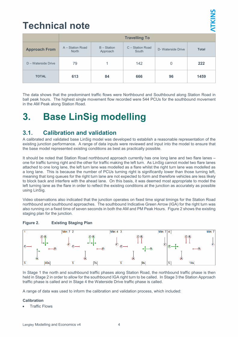
The data shows that the predominant traffic flows were Northbound and Southbound along Station Road in ball peak hours. The highest single movement flow recorded were 544 PCUs for the southbound movement in the AM Peak along Station Road.
3. Base LinSig modelling
3.1. Calibration and validation A calibrated and validated base LinSig model was developed to establish a reasonable representation of the existing junction performance. A range of data inputs were reviewed and input into the model to ensure that the base model represented existing conditions as best as practically possible.
It should be noted that Station Road northbound approach currently has one long lane and two flare lanes – one for traffic turning right and the other for traffic making the left turn. As LinSig cannot model two flare lanes attached to one long lane, the left turn lane was modelled as a flare whilst the right turn lane was modelled as a long lane. This is because the number of PCUs turning right is significantly lower than those turning left, meaning that long queues for the right turn lane are not expected to form and therefore vehicles are less likely to block back and interfere with the ahead lane. On this basis, it was deemed most appropriate to model the left turning lane as the flare in order to reflect the existing conditions at the junction as accurately as possible using LinSig.
Video observations also indicated that the junction operates on fixed time signal timings for the Station Road northbound and southbound approaches. The southbound Indicative Green Arrow (IGA) for the right turn was also running on a fixed time of seven seconds in both the AM and PM Peak Hours. Figure 2 shows the existing staging plan for the junction.
Figure 2. Existing Staging Plan
In Stage 1 the north and southbound traffic phases along Station Road, the northbound traffic phase is then held in Stage 2 in order to allow for the southbound IGA right turn to be called. In Stage 3 the Station Approach traffic phase is called and in Stage 4 the Waterside Drive traffic phase is called.
A range of data was used to inform the calibration and validation process, which included:
Calibration
Traffic Flows

Langley Modelling and Economics v4 5
Technical note - Origin Destination classified counts – the movements were coded into the LinSig model and the lane
based assignment tool imbedded in LinSig was then used to allocate flows to the corresponding lanes. - Lane SAT flows were geometrically calculated using the RR67 formula.
Signal Timings - Average Green time surveys – the traffic survey videos were used to derive an average green time for
each of the approaches; - Cycle time surveys – the cycle times were extracted from the Traffic Signal Specifications obtained
from SBC and cross checked against the video surveys; and - Under-utilised green time (UGT) – this corresponded to the number of seconds within a signal cycle
where saturation flow was not achieved, despite the presence of stop line demand. In order to analyse the UGT at selected lanes of the junction, time at start of green, time at start of full demand, time at end of full demand, time at end of green and time at end of amber were recorded along with a classified count of each PCU type that passed the stop line during and after high demand.
A summary of the observed data used for model calibration is shown in Table 4.
Table 4. Summary of Calibration Data
Approach
AM PM
Observed Cycle Time
Observed Green Time
Observed UGT
Observed Cycle Time
Observed Green Time
Observed UGT
Arm A – Station Road north
90
52 5
91
52 3
Arm A – Station Road north Indicative Right
7 - 7 -
Arm C – Station Road south
40 1 40 2
Validation
Operational performance indicators - Degree of Saturation (DoS) surveys – the DoS provides an indication of the level of spare capacity left
on a lane and whether this has been exceeded. The DoS on selected lanes was surveyed using the video surveys; and
- Mean Maximum Queue surveys – observational queue data was not available from the survey however this is not considered a critical component of network validation for LINSIG models.
The DoS was used as the primary validation parameter as it is considered the most robust approach to show that the calibrated model results accurately reflected the observed on-street junction performance.
3.2. Base model results This section summaries the results of the base LinSig modelling.
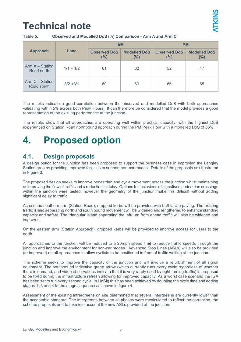
The base LinSig model DoS for Station Road northbound and southbound approaches (Arms A and C) are presented in Table 5. The AM Peak was modelled with a cycle time of 90 seconds whilst the PM Peak was modelled with a cycle time of 91 seconds. These cycle times were derived from observations from the high mast video surveys. Video footage was only available to observe the northbound and southbound Station Road approaches which were the most heavily used at the junction. As such, Arms B and D were not included in the analysis, however the flows on these approaches were low in comparison to the two major approaches of Station Road.
The table below shows a comparison between the observed and modelled DoS and demonstrates that the model provides a reasonable representation of the existing operation of the junction. The lanes with the highest flows on each of the approaches have been validated to an observed DoS. It should be noted that where flares are present, lane results have been combined with the associated long lane that feeds them.
Langley Modelling and Economics v4 6
Technical note Table 5. Observed and Modelled DoS (%) Comparison - Arm A and Arm C
Approach Lane
AM PM
Observed DoS (%)
Modelled DoS (%)
Observed DoS (%)
Modelled DoS (%)
Arm A – Station Road north
1/1 + 1/2 61 62 52 47
Arm C – Station Road south
3/2 +3/1 60 63 66 65
The results indicate a good correlation between the observed and modelled DoS with both approaches validating within 5% across both Peak Hours. It can therefore be considered that the model provides a good representation of the existing performance at the junction.
The results show that all approaches are operating well within practical capacity, with the highest DoS experienced on Station Road northbound approach during the PM Peak Hour with a modelled DoS of 66%.
4. Proposed option
4.1. Design proposals A design option for the junction has been proposed to support the business case in improving the Langley Station area by providing improved facilities to support non-car modes. Details of the proposals are illustrated in Figure 3.
The proposed design seeks to improve pedestrian and cycle movement across the junction whilst maintaining or improving the flow of traffic and a reduction in delay. Options for inclusions of signalised pedestrian crossings within the junction were tested, however the geometry of the junction make this difficult without adding significant delay to traffic.
Across the southern arm (Station Road), dropped kerbs will be provided with buff tactile paving. The existing traffic island separating north and south bound movement will be widened and lengthened to enhance standing capacity and safety. The triangular island separating the left-turn from ahead traffic will also be widened and improved.
On the eastern arm (Station Approach), dropped kerbs will be provided to improve access for users to the north.
All approaches to the junction will be reduced to a 20mph speed limit to reduce traffic speeds through the junction and improve the environment for non-car modes. Advanced Stop Lines (ASLs) will also be provided (or improved) on all approaches to allow cyclists to be positioned in front of traffic waiting at the junction.
The scheme seeks to improve the capacity of the junction and will involve a refurbishment of all signal equipment. The southbound indicative green arrow (which currently runs every cycle regardless of whether there is demand, and video observations indicate that it is very rarely used by right turning traffic) is proposed to be fixed during the infrastructure refresh allowing for improved capacity. As a worst case scenario the IGA has been set to run every second cycle. In LinSig this has been achieved by doubling the cycle time and adding stages 1, 3 and 4 to the stage sequence as shown in figure 4.
Assessment of the existing intrergreens on site determined that several intergreens are currently lower than the acceptable standard. The intergreens between all phases were recalculated to reflect the correction, the scheme proposals and to take into account the new ASLs provided at the junction.

Langley Modelling and Economics v4 7
Technical note Figure 3. Proposed Langley Station and Access Improvements scheme
Figure 4. Proposed Staging Plan

Langley Modelling and Economics v4 8
Technical note 4.2. Base year modelling output comparison
4.2.1. Modelling outputs Table 6 provides a comparison of the DoS results between the base LinSig model and the proposed model across the four approaches and identified Peak Hours.
Table 6. DoS comparison of base and proposed models (2016 base year)
Approach Lane
AM Inter peak PM
Base Model
DoS (%)
Proposed Model
DoS (%)
Base Model DoS (%)
Proposed Model DoS
(%)
Base Model DoS (%)
Proposed Model DoS
(%)
Arm A – Station Road
north 1/1 + 1/2 62 54 38 40 47 46
Arm B – Station
Approach 2/1 47 59 37 37 46 63
Arm C – Station Road
south
3/1 11 12 5 5 5 5
3/2+3/3 60 45 48 46 65 54
Arm D – Waterside
Drive 4/2+4/1 25 45 49 49 54 61
Total network delay (pcu/hr)
9.66 7.67 5.97 5.95 10.67 10.13
The results indicate that the removal of the indicative green arrow reduces the amount of total network delay in the junction. All approaches in all time periods are forecast to operate within practical capacity.
The greatest impact will be in the AM peak with delay reduced by 2.26 pcu/hrs.
5. Future year modelling
5.1. Background growth For the purposes of estimating the economic impact (on transport users) of the scheme two future year scenarios were tested:
2018 – opening year
2028 – future year
And two model scenarios:
Do minimum – existing network plus background growth
Do something – proposed network plus background growth plus additional demand
Background growth for the network has been calculated using TEMPRO 7. The TEMPRO areas considered for uplifting the 2011 base year matrix are:
Regional/County: SE England, Berkshire, Slough, South Bucks

Langley Modelling and Economics v4 9
Technical note Authority: Slough, South Buckinghamshire
Local (MSOA): Slough 010, Slough 013, Slough 014. South Bucks 005, South Bucks 008
TEMPRO growth factors were obtained for the considered areas, for 2016 to 2018 and from 2018 to 2026 and for AM, interpeak and PM peak periods.
Since TEMPRO takes only population and employment changes into account and not external factors such as the changing costs of travel, changing values of time, or changes in trip lengths, NTM AF15 has also been used to forecast traffic growth. This approach is in line with TAG Unit M4, Section 9.
The principle is that general traffic growth forecasts (from NTM) are adjusted to local housing and employment growth forecasts (using TEMPRO factors), applying the following formula:
Adjusted local peak period growth factor = NTM average day traffic growth factor x (TEMPRO peak period trip growth factor / TEMPRO average day trip growth factor).
TEMPRO peak period growth factors are shown in Table 7. The full TEMPRO calculations are provided in Appendix A.
Table 7. TEMPRO background growth factors
Base year Future year TEMPRO Factor
AM peak IP PM peak
2016 2018 1.022981 1.026291 1.022841
2016 2028 1.143353 1.170431 1.145215
5.2. Scheme related growth The Langley Station and Access Improvement scheme is primarily a public realm scheme. At present the junction is not congested for prolonged periods, and the modelling detailed above shows sufficient spare capacity. It is unlikely therefore that there is any supressed demand which would chose to use the route because of the proposals themselves.
However, the scheme does involve the promotion of additional parking on a neighbouring road. It is understood that much of the existing pay and display parking on Waterside Drive is under-utilised (site surveys showed peak occupancy to be 30% of capacity) there to be despite there being evidence the station car park is at capacity on a daily basis.
The signage relating to the parking controls on Waterside Drive states that cars can park for a maximum of 8 hours and may be preventing potential commuters using the spaces, before continuing their journey by rail. However, the actual charged period for the spaces is 9am to 5pm (i.e. 8 hours) and users would actually be free to park either side of that period.
It is anticipated that with clearer information and signage users would be willing to use the parking on Waterside Drive. These potential users could be:
existing rail users who either don’t currently drive
existing rail users who park informally on Station Approach (which will be discouraged in proposals for the scheme)
or new users resulting from increased rail demand
There is the potential for 21 additional cars to park on Waterside Drive were all spaces to be taken up. As a worst case scenario it has been assumed that the proposed scheme leads to the take up of all 21 spaces, and that each user parks in the morning peak hour and leaves in the PM peak hour. These trips have been
Langley Modelling and Economics v4 10
Technical note distributed according to existing proportions (which shows 66% from/to south and 34% from/to the north in both peaks.
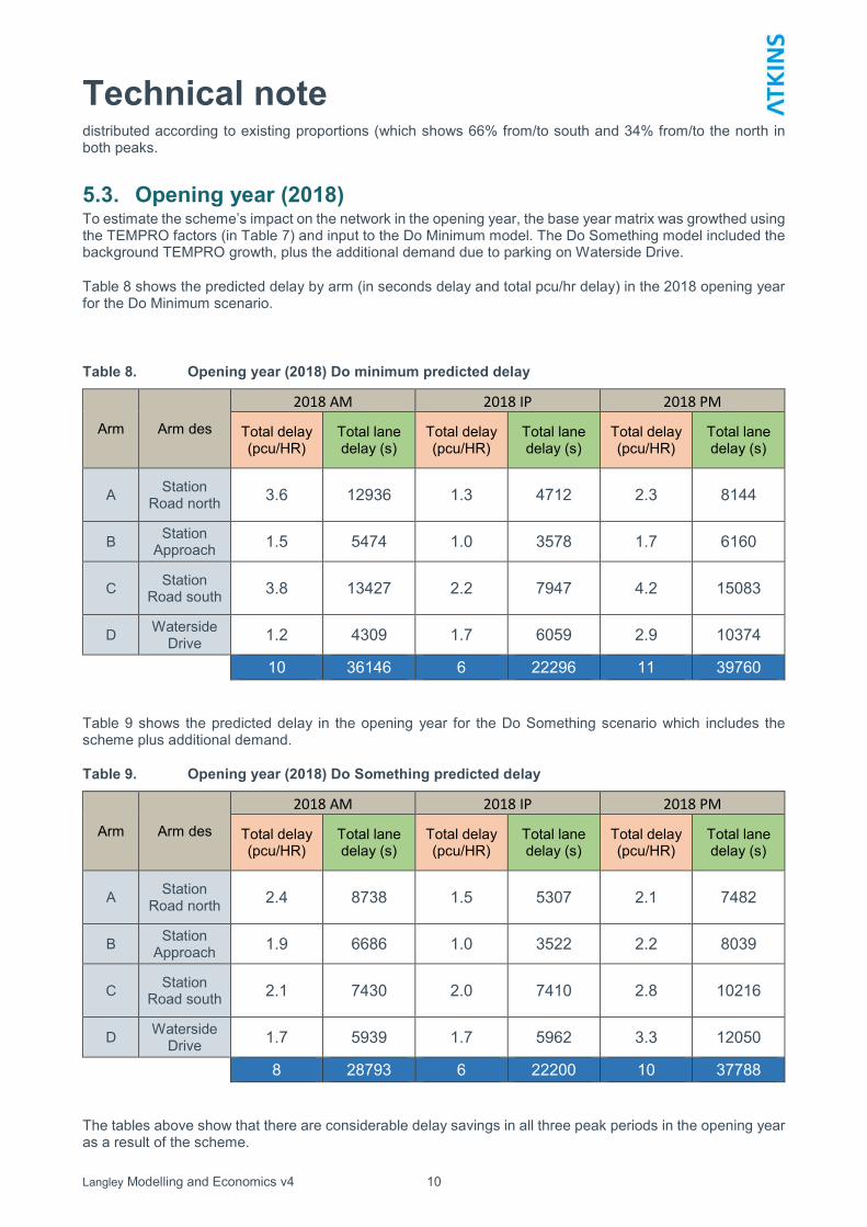
5.3. Opening year (2018) To estimate the scheme’s impact on the network in the opening year, the base year matrix was growthed using the TEMPRO factors (in Table 7) and input to the Do Minimum model. The Do Something model included the background TEMPRO growth, plus the additional demand due to parking on Waterside Drive.
Table 8 shows the predicted delay by arm (in seconds delay and total pcu/hr delay) in the 2018 opening year for the Do Minimum scenario.
Table 8. Opening year (2018) Do minimum predicted delay
Arm Arm des
2018 AM 2018 IP 2018 PM
Total delay (pcu/HR)
Total lane delay (s)
Total delay (pcu/HR)
Total lane delay (s)
Total delay (pcu/HR)
Total lane delay (s)
A Station
Road north 3.6 12936 1.3 4712 2.3 8144
B Station
Approach 1.5 5474 1.0 3578 1.7 6160
C Station
Road south 3.8 13427 2.2 7947 4.2 15083
D Waterside
Drive 1.2 4309 1.7 6059 2.9 10374
10 36146 6 22296 11 39760
Table 9 shows the predicted delay in the opening year for the Do Something scenario which includes the scheme plus additional demand.
Table 9. Opening year (2018) Do Something predicted delay
Arm Arm des
2018 AM 2018 IP 2018 PM
Total delay (pcu/HR)
Total lane delay (s)
Total delay (pcu/HR)
Total lane delay (s)
Total delay (pcu/HR)
Total lane delay (s)
A Station
Road north 2.4 8738 1.5 5307 2.1 7482
B Station
Approach 1.9 6686 1.0 3522 2.2 8039
C Station
Road south 2.1 7430 2.0 7410 2.8 10216
D Waterside
Drive 1.7 5939 1.7 5962 3.3 12050
8 28793 6 22200 10 37788
The tables above show that there are considerable delay savings in all three peak periods in the opening year as a result of the scheme.

Langley Modelling and Economics v4 11
Technical note 5.4. Future year (2028) The Do Minimum and Do Something networks were also run for a further future year (2028).
Table 10 shows the predicted delay by arm (in seconds delay and total pcu/hr delay) in the 2028 future year for the Do Minimum scenario.
Table 10. Future year (2028) Do minimum predicted delay
Arm Arm des
2028 AM 2028 IP 2028 PM
Total delay (pcu/HR)
Total lane delay (s)
Total delay (pcu/HR)
Total lane delay (s)
Total delay (pcu/HR)
Total lane delay (s)
A Station
Road north 4.5 16118 1.6 5763 2.7 9707
B Station
Approach 1.7 6294 1.2 4146 2.0 7143
C Station
Road south 4.6 16479 2.7 9791 5.2 18747
D Waterside
Drive 1.3 4839 2.0 7198 3.4 12141
12 43730 8 26899 13 47738
Table 11 shows the predicted delay in the opening year for the Do Something scenario which includes the scheme plus additional demand.
Table 11. Opening year (2018) Do Something predicted delay
Arm Arm des
2018 AM 2018 IP 2018 PM
Total delay (pcu/HR)
Total lane delay (s)
Total delay (pcu/HR)
Total lane delay (s)
Total delay (pcu/HR)
Total lane delay (s)
A Station
Road north 3.0 10639 1.8 6498 2.6 9364
B Station
Approach 2.2 7997 1.1 4083 2.6 9187
C Station
Road south 2.5 8910 2.5 9118 3.6 12990
D Waterside
Drive 1.9 6795 2.0 7076 3.8 13776
10 34341 7 26774 13 45318
6. Economic calculations
6.1. Methodology The outputs of the LinSig modelling exercise described in the preceding sections have been used to estimate the likely economic benefit which will be realised by implementing the highway element of the Langley Station and Access Improvements scheme.

Langley Modelling and Economics v4 12
Technical note In keeping with the proportional approach prescribed for smaller LEP funded schemes, a full TUBA based economic appraisal has not been undertaken. Instead, user time benefits and disbenefits associated with the changes to the junction have been captured using a spreadsheet model assessment based upon the delay outputs of the transport model.
The steps taken to determine a Present Value of Benefit associated solely with the journey time impact on transport users is described below.
Step 1 – annualisation of impacts
The tables in Section 5 provide the peak hour anticipated delays at the junction in the Do Minimum and Do Something scenarios for 2018 and 2028 future years. The benefits for the AM and PM peak hours and the IP period have then been annualised using a factor of 253 to provide an annual benefit in pcu/hrs.
Step 2 – split by journey purpose
Journey purpose splits have been taken from the WebTAG databook (Summer 2016) table A1.3.4.
Business – 16.4%
Commuter – 31%
Leisure – 52.5%
Business trips were further split by mode (Car/LGV/OGV) to account for the differences in Value of Time and occupancy. This split was based on the traffic composition observed in the traffic survey undertaken by Tracsis Plc.
Therefore the journey purpose split used is:
Business/Car – 6.87%
Business/LGV – 6.75%
Business/OGV – 2.78%
Commuter – 31%
Leisure - 52.5%
Step 3 – calculation of benefits by purpose
Journey time benefits for each purpose group have been then monetized using WebTAG’s Value of Time (WebTAG databook (Summer 2016), table A1.3.2), and multiplied by an occupancy factor taken from the WebTAG databook (Summer 2016, table A1.3.3). Finally, benefits are discounted to 2010 using discount rates taken from the WebTAG databook (Summer 2016, table A1.1.1).
The overall Present Value Benefits (in 2010 prices, discounted to 2010) are £183,916 PV.
7. Conclusions
The removal of the Indicative Green Arrow for southbound right-turners from the signal method of control has a positive impact on delays and the overall operation of the junction. This is despite adding or improving Advance Stop Lines for cyclists, and increasing intergreen times to meet standard guidance.
The issue of the IGA being called every cycle has been resolved, and has (as a worst case scenario) been set to run every second cycle. Only a small number of vehicles were observed to turn right into Waterside Drive, and these very rarely used the IGA to clear the junction. Although the number of right turning PCUs is

Langley Modelling and Economics v4 13
Technical note higher in the AM Peak, they are comparable to the right turning vehicles on the opposing northbound approach which operates as a give-way approach.
The reduction in delay at the junction is shown to produce an improvement in performance in both operational and economic terms.

Langley Modelling and Economics v4
Technical note
Appendix A – TEMPRO Factors

TEMPRO 2016_2018
Growth Factor _Weekday AM Peak Period Growth Factor _Average Day Growth Factor _NTM
Area Description All purposes Area Description All purposes
Level Name Origin Destination Level Name Origin Destination Level Area Local Growth FigureAdjusted Growth Factor
GB GB 1.0167 1.0167 GB GB 1.0174 1.0174
Region SE 1.0181 1.0178 Region SE 1.0186 1.0187 Region SE 1.0302 1.0295
County Berkshire 1.0189 1.0181 County Berkshire 1.0193 1.0193 County Berkshire 1.0309 1.0301
Authority Slough 1.0173 1.0171 Authority Slough 1.0172 1.0172 Authority Slough 1.0288 1.0288
E02003416 Slough 010 1.0145 1.0138 E02003416 Slough 010 1.0146 1.0147 E02003416 Slough 010 1.0262 1.0257
E02003419 Slough 013 1.0183 1.0209 E02003419 Slough 013 1.0207 1.0203 E02003419 Slough 013 1.0321 1.0312
E02003420 Slough 014 1.0157 1.0173 E02003420 Slough 014 1.0169 1.0166 E02003420 Slough 014 1.0283 1.0281
Authority South Bucks 1.0022 0.9991 Authority South Bucks 1.0022 1.0027 Authority South Bucks 1.0139 1.0120
E02003692 South Bucks 005 1.0015 0.9983 E02003692 South Bucks 005 1.0005 1.0012 E02003692 South Bucks 005 1.0122 1.0113
E02003695 South Bucks 008 1.0004 0.9973 E02003695 South Bucks 008 1.0015 1.002 E02003695 South Bucks 008 1.0131 1.0102
Average Growth 1.0124 1.0116 1.0129 1.0130 1.0240 1.0230
Growth Factor _Weekday PM Peak Period Growth Factor _Average Day Growth Factor _NTM
Area Description All purposes Area Description All purposes
Level Name Origin Destination Level Name Origin Destination Level Area Local Growth FigureAdjusted Growth Factor
GB GB 1.0163 1.0163 GB GB 1.0174 1.0174
Region SE 1.0175 1.0177 Region SE 1.0186 1.0187 Region SE 1.0302 1.0292
County Berkshire 1.0179 1.0184 County Berkshire 1.0193 1.0193 County Berkshire 1.0309 1.0297
Authority Slough 1.0165 1.0165 Authority Slough 1.0172 1.0172 Authority Slough 1.0288 1.0281
E02003416 Slough 010 1.0132 1.014 E02003416 Slough 010 1.0146 1.0147 E02003416 Slough 010 1.0262 1.0251
E02003419 Slough 013 1.0212 1.0185 E02003419 Slough 013 1.0207 1.0203 E02003419 Slough 013 1.0321 1.0314
E02003420 Slough 014 1.0168 1.0149 E02003420 Slough 014 1.0169 1.0166 E02003420 Slough 014 1.0283 1.0274
Authority South Bucks 0.9991 1.0028 Authority South Bucks 1.0022 1.0027 Authority South Bucks 1.0139 1.0123
E02003692 South Bucks 005 0.9971 1.0014 E02003692 South Bucks 005 1.0005 1.0012 E02003692 South Bucks 005 1.0122 1.0106
E02003695 South Bucks 008 0.9985 1.0021 E02003695 South Bucks 008 1.0015 1.002 E02003695 South Bucks 008 1.0131 1.0117
Average Growth 1.0114 1.0123 1.0129 1.0130 1.0240 1.0228
Growth Factor _Weekday IP Peak Period Growth Factor _Average Day Growth Factor _NTM
Area Description All purposes Area Description All purposes
Level Name Origin Destination Level Name Origin Destination Level Area Local Growth FigureAdjusted Growth Factor
GB GB 1.0197 1.0197 GB GB 1.0174 1.0174
Region SE 1.0211 1.0211 Region SE 1.0186 1.0187 Region SE 1.0302 1.0327
County Berkshire 1.0221 1.0221 County Berkshire 1.0193 1.0193 County Berkshire 1.0309 1.0337
Authority Slough 1.0189 1.019 Authority Slough 1.0172 1.0172 Authority Slough 1.0288 1.0305
E02003416 Slough 010 1.017 1.017 E02003416 Slough 010 1.0146 1.0147 E02003416 Slough 010 1.0262 1.0286
E02003419 Slough 013 1.0231 1.0227 E02003419 Slough 013 1.0207 1.0203 E02003419 Slough 013 1.0321 1.0345
E02003420 Slough 014 1.0185 1.018 E02003420 Slough 014 1.0169 1.0166 E02003420 Slough 014 1.0283 1.0298
Authority South Bucks 1.0047 1.0051 Authority South Bucks 1.0022 1.0027 Authority South Bucks 1.0139 1.0163
E02003692 South Bucks 005 1.0026 1.0029 E02003692 South Bucks 005 1.0005 1.0012 E02003692 South Bucks 005 1.0122 1.0142
E02003695 South Bucks 008 1.0045 1.0051 E02003695 South Bucks 008 1.0015 1.002 E02003695 South Bucks 008 1.0131 1.0162
Average Growth 1.0152 1.0153 1.0129 1.0130 1.0240 1.0263

TEMPRO 2016_2028
Growth Factor _Weekday AM Peak Period Growth Factor _Average Day Growth Factor _NTM
Area Description All purposes Area Description All purposes
Level Name Origin Destination Level Name Origin Destination Level Area Local Growth FigureAdjusted Growth Factor
GB GB 1.0929 1.0929 GB GB 1.0995 1.0995
Region SE 1.0946 1.0957 Region SE 1.1041 1.1042 Region SE 1.17454458 1.1650
County Berkshire 1.1062 1.0943 County Berkshire 1.1094 1.1095 County Berkshire 1.18018248 1.1704
Authority Slough 1.1073 1.0908 Authority Slough 1.1053 1.1055 Authority Slough 1.17587427 1.1691
E02003416 Slough 010 1.0991 1.0809 E02003416 Slough 010 1.0983 1.0992 E02003416 Slough 010 1.16880031 1.1595
E02003419 Slough 013 1.114 1.1017 E02003419 Slough 013 1.1179 1.1169 E02003419 Slough 013 1.18863933 1.1785
E02003420 Slough 014 1.0978 1.0872 E02003420 Slough 014 1.0956 1.0954 E02003420 Slough 014 1.1653431 1.1622
Authority South Bucks 1.0264 1.041 Authority South Bucks 1.0445 1.0462 Authority South Bucks 1.11199581 1.0996
E02003692 South Bucks 005 1.0242 1.0383 E02003692 South Bucks 005 1.0396 1.0416 E02003692 South Bucks 0051.10694298 1.0970
E02003695 South Bucks 008 1.0142 1.0332 E02003695 South Bucks 008 1.0363 1.0382 E02003695 South Bucks 0081.1033794 1.0890
Average Growth 1.0777 1.0756 1.0851 1.0856 1.1529 1.1434
Growth Factor _Weekday PM Peak Period Growth Factor _Average Day Growth Factor _NTM
Area Description All purposes Area Description All purposes
Level Name Origin Destination Level Name Origin Destination Level Area Local Growth FigureAdjusted Growth Factor
GB GB 1.0927 1.0927 GB GB 1.0995 1.0995
Region SE 1.0962 1.0956 Region SE 1.1041 1.1042 Region SE 1.17454458 1.1658
County Berkshire 1.0974 1.1058 County Berkshire 1.1094 1.1095 County Berkshire 1.18018248 1.1718
Authority Slough 1.0932 1.1053 Authority Slough 1.1053 1.1055 Authority Slough 1.17587427 1.1693
E02003416 Slough 010 1.0845 1.1003 E02003416 Slough 010 1.0983 1.0992 E02003416 Slough 010 1.16880031 1.1620
E02003419 Slough 013 1.1084 1.1151 E02003419 Slough 013 1.1179 1.1169 E02003419 Slough 013 1.18863933 1.1826
E02003420 Slough 014 1.0875 1.0943 E02003420 Slough 014 1.0956 1.0954 E02003420 Slough 014 1.1653431 1.1604
Authority South Bucks 1.0388 1.0339 Authority South Bucks 1.0445 1.0462 Authority South Bucks 1.11199581 1.1024
E02003692 South Bucks 005 1.0334 1.0304 E02003692 South Bucks 005 1.0396 1.0416 E02003692 South Bucks 0051.10694298 1.0977
E02003695 South Bucks 008 1.0333 1.025 E02003695 South Bucks 008 1.0363 1.0382 E02003695 South Bucks 0081.1033794 1.0948
Average Growth 1.0765 1.0798 1.0851 1.0856 1.1529 1.1452
Growth Factor _Weekday IP Peak Period Growth Factor _Average Day Growth Factor _NTM
Area Description All purposes Area Description All purposes
Level Name Origin Destination Level Name Origin Destination Level Area Local Growth FigureAdjusted Growth Factor
GB GB 1.1139 1.1139 GB GB 1.0995 1.0995
Region SE 1.1223 1.1221 Region SE 1.1041 1.1042 Region SE 1.17454458 1.1937
County Berkshire 1.127 1.1273 County Berkshire 1.1094 1.1095 County Berkshire 1.18018248 1.1990
Authority Slough 1.1197 1.1205 Authority Slough 1.1053 1.1055 Authority Slough 1.17587427 1.1915
E02003416 Slough 010 1.1133 1.1153 E02003416 Slough 010 1.0983 1.0992 E02003416 Slough 010 1.16880031 1.1853
E02003419 Slough 013 1.1342 1.1334 E02003419 Slough 013 1.1179 1.1169 E02003419 Slough 013 1.18863933 1.2061
E02003420 Slough 014 1.1081 1.1091 E02003420 Slough 014 1.0956 1.0954 E02003420 Slough 014 1.1653431 1.1793
Authority South Bucks 1.0636 1.0632 Authority South Bucks 1.0445 1.0462 Authority South Bucks 1.11199581 1.1312
E02003692 South Bucks 005 1.057 1.0561 E02003692 South Bucks 005 1.0396 1.0416 E02003692 South Bucks 0051.10694298 1.1239
E02003695 South Bucks 008 1.0563 1.0566 E02003695 South Bucks 008 1.0363 1.0382 E02003695 South Bucks 0081.1033794 1.1238
Average Growth 1.1015 1.1018 1.0851 1.0856 1.1529 1.1704

Langley Modelling and Economics v4
Technical note
Appendix B – Do Minimum LinSig outputs

Full Input Data And Results
Full Input Data And Results User and Project Details
Project: Langley Station Business Case
Title: Base and do minimum scenarios
Location:
File name: LinSig Model - Langley Station Base Model.lsg3x
Author:
Company:
Address:
Notes:
Network Layout Diagram

Full Input Data And Results
Phase Diagram
A
BC
D
E
F
Phase Input Data
Phase Name Phase Type Assoc. Phase Street Min Cont Min
A Traffic 7 7
B Traffic 7 7
C Ind. Arrow B 4 4
D Traffic 7 7
E Traffic 7 7
F Dummy R/A 7 7

Full Input Data And Results
Phase Intergreens Matrix
Starting Phase
Terminating Phase
A B C D E F
A - - 5 5 5 2
B - - - 5 5 2
C 5 - - 5 5 2
D 5 5 5 - 5 2
E 5 5 5 5 - 2
F 3 3 3 3 3 -
Phases in Stage
Stage No. Phases in Stage
1 A B
2 B C
3 D
4 E
Stage Diagram
A
BC
DE
F
1 Min >= 7
A
BC
DE
F
2 Min >= 4
A
BC
DE
F
3 Min >= 7
A
BC
DE
F
4 Min >= 7
Phase Delays
Term. Stage Start Stage Phase Type Value Cont value
There are no Phase Delays defined
Prohibited Stage Change
To Stage
From Stage
1 2 3 4
1 5 5 5
2 5 5 5
3 5 5 5
4 5 5 5

Full Input Data And Results
Give-Way Lane Input Data
Junction: Unnamed Junction
Lane Movement
Max Flow when
Giving Way (PCU/Hr)
Min Flow when
Giving Way (PCU/Hr)
Opposing Lane
Opp. Lane Coeff.
Opp. Mvmnts.
Right Turn Storage (PCU)
Non-Blocking Storage (PCU)
RTF Right Turn Move up (s)
Max Turns in Intergreen
(PCU)
1/2 (Station Road (Southbound) )
8/1 (Right) 1439 0 3/2 1.09 All 2.00 - 0.50 2 2.00
3/1 (Station Road (Northbound))
8/1 (Left) 1439 0 1/2 1.09 All
- - - - - 2/1 1.09 To 8/1 (Ahead)
3/3 (Station Road (Northbound))
6/1 (Right) 1439 0 1/1 1.09 All 4.00 - 0.50 4 3.00

Full Input Data And Results
Lane Input Data
Junction: Unnamed Junction
Lane Lane Type
Phases Start Disp.
End Disp.
Physical Length (PCU)
Sat Flow Type
Def User Saturation
Flow (PCU/Hr)
Lane Width
(m) Gradient
Nearside Lane
Turns Turning Radius
(m)
1/1 (Station Road (Southbound) )
U B 2 3 60.0 Geom - 3.00 0.00 Y
Arm 6 Left
40.00
Arm 7 Ahead
Inf
1/2 (Station Road (Southbound) )
O B C 2 3 3.5 Geom - 2.50 0.00 Y Arm 8 Right
40.00
2/1 (Station
Approach) U D 2 3 60.0 Geom - 3.25 0.00 Y
Arm 5 Right
40.00
Arm 7 Left
45.00
Arm 8 Ahead
Inf
3/1 (Station Road (Northbound))
O 2 3 6.1 Geom - 4.00 0.00 Y Arm 8 Left
50.00
3/2 (Station Road (Northbound))
U A 2 3 60.0 Geom - 2.70 0.00 Y Arm 5 Ahead
Inf
3/3 (Station Road (Northbound))
O A 2 3 3.8 Geom - 2.70 0.00 Y Arm 6 Right
40.00
4/1 (Waterside
Drive) U E 2 3 7.0 Geom - 2.70 0.00 Y
Arm 5 Left
30.00
Arm 6 Ahead
Inf
4/2 (Waterside
Drive) U E 2 3 60.0 Geom - 2.70 0.00 Y
Arm 7 Right
50.00
5/1 U 2 3 60.0 Inf - - - - - -
6/1 U 2 3 60.0 Inf - - - - - -
7/1 U 2 3 60.0 Inf - - - - - -
8/1 U 2 3 60.0 Inf - - - - - -
Scenario 1: 'AM Peak' (FG1: 'AM Peak', Plan 1: 'Network Control Plan 1')
Stage Sequence Diagram
A
B
1 Min: 7
5 40s
BC
2 Min: 4
5 7s
D
3 Min: 7
5 9s
E
4 Min: 7
5 14s Stage Timings
Stage 1 2 3 4
Duration 40 7 9 14
Change Point 0 45 57 71

Full Input Data And Results
Signal Timings Diagram
0
0
10
10
20
20
30
30
40
40
50
50
60
60
70
70
80
80
90
90
Time in cycle (sec)
Phases
1 5 : 40
0
2 5 : 7
45
3 5 : 9
57
4 5 : 14
71
F F
E E
D D
C C
B B
A A

Full Input Data And Results
Network Results
Item Lane Description Lane Type
Controller Stream
Position In Filtered Route
Full Phase Arrow Phase
Num Greens
Total Green (s)
Arrow Green (s)
Demand Flow (pcu)
Sat Flow (pcu/Hr)
Capacity (pcu)
Deg Sat (%)
Network - - N/A - - - - - - - - 62.3%
Unnamed Junction
- - N/A - - - - - - - - 62.3%
1/1+1/2 Station Road
(Southbound) Left Ahead Right
U+O N/A N/A B C 1 52 7 644 1911:1798 918+116 62.3 : 62.3%
2/1 Station Approach Right Left Ahead
U N/A N/A D 1 9 - 98 1878 209 47.0%
3/1 Station Road
(Northbound) Left O N/A N/A - - - - 148 1956 1358 10.9%
3/2+3/3 Station Road (Northbound) Ahead Right
U+O N/A N/A A 1 40 - 516 1885:1817 752+116 59.5 : 59.5%
4/2+4/1 Waterside Drive Left Ahead Right
U N/A N/A E 1 14 - 111 1830:1809 293+153 24.9 : 24.9%
5/1 U N/A N/A - - - - 502 Inf Inf 0.0%
6/1 U N/A N/A - - - - 103 Inf Inf 0.0%
7/1 U N/A N/A - - - - 688 Inf Inf 0.0%
8/1 U N/A N/A - - - - 224 Inf Inf 0.0%

Full Input Data And Results
Item Arriving (pcu) Leaving (pcu)
Turners In Gaps (pcu)
Turners When Unopposed (pcu)
Turners In Intergreen (pcu)
Uniform Delay (pcuHr)
Rand + Oversat Delay (pcuHr)
Storage Area Uniform Delay (pcuHr)
Total Delay (pcuHr)
Av. Delay Per PCU (s/pcu)
Max. Back of Uniform Queue (pcu)
Rand + Oversat Queue (pcu)
Mean Max Queue (pcu)
Network - - 234 53 2 7.1 2.2 0.3 9.7 - - - -
Unnamed Junction
- - 234 53 2 7.1 2.2 0.3 9.7 - - - -
1/1+1/2 644 644 62 9 2 2.5 0.8 0.1 3.4 19.2 10.7 0.8 11.5
2/1 98 98 - - - 1.0 0.4 - 1.5 53.7 2.3 0.4 2.7
3/1 148 148 104 44 0 0.0 0.1 - 0.1 1.5 0.0 0.1 0.1
3/2+3/3 516 516 69 0 0 2.6 0.7 0.2 3.5 24.6 8.9 0.7 9.6
4/2+4/1 111 111 - - - 1.0 0.2 - 1.2 37.7 1.6 0.2 1.7
5/1 502 502 - - - 0.0 0.0 - 0.0 0.0 0.0 0.0 0.0
6/1 103 103 - - - 0.0 0.0 - 0.0 0.0 0.0 0.0 0.0
7/1 688 688 - - - 0.0 0.0 - 0.0 0.0 0.0 0.0 0.0
8/1 224 224 - - - 0.0 0.0 - 0.0 0.0 0.0 0.0 0.0
C1 PRC for Signalled Lanes (%): 44.4 Total Delay for Signalled Lanes (pcuHr): 9.59 Cycle Time (s): 90 PRC Over All Lanes (%): 44.4 Total Delay Over All Lanes(pcuHr): 9.66

Full Input Data And Results Scenario 2: 'PM Peak' (FG2: 'PM Peak', Plan 1: 'Network Control Plan 1')
Stage Sequence Diagram
A
B
1 Min: 7
5 40s
BC
2 Min: 4
5 7s
D
3 Min: 7
5 12s
E
4 Min: 7
5 12s Stage Timings
Stage 1 2 3 4
Duration 40 7 12 12
Change Point 6 51 63 80
Signal Timings Diagram
0
0
10
10
20
20
30
30
40
40
50
50
60
60
70
70
80
80
90
90
Time in cycle (sec)
Phases
1 5 : 40
6
2 5 : 7
51
3 5 : 12
63
4 5 : 12
80
F F
E E
D D
C C
B B
A A

Full Input Data And Results
Network Results
Item Lane Description Lane Type
Controller Stream
Position In Filtered Route
Full Phase Arrow Phase
Num Greens
Total Green (s)
Arrow Green (s)
Demand Flow (pcu)
Sat Flow (pcu/Hr)
Capacity (pcu)
Deg Sat (%)
Network - - N/A - - - - - - - - 65.1%
Unnamed Junction
- - N/A - - - - - - - - 65.1%
1/1+1/2 Station Road
(Southbound) Left Ahead Right
U+O N/A N/A B C 1 52 7 498 1910:1798 1017+38 47.2 : 47.2%
2/1 Station Approach Right Left Ahead
U N/A N/A D 1 12 - 124 1878 268 46.2%
3/1 Station Road
(Northbound) Left O N/A N/A - - - - 72 1956 1413 5.1%
3/2+3/3 Station Road (Northbound) Ahead Right
U+O N/A N/A A 1 40 - 541 1885:1817 754+77 65.1 : 65.1%
4/2+4/1 Waterside Drive Left Ahead Right
U N/A N/A E 1 12 - 222 1830:1796 261+147 54.3 : 54.3%
5/1 U N/A N/A - - - - 613 Inf Inf 0.0%
6/1 U N/A N/A - - - - 83 Inf Inf 0.0%
7/1 U N/A N/A - - - - 665 Inf Inf 0.0%
8/1 U N/A N/A - - - - 96 Inf Inf 0.0%

Full Input Data And Results
Item Arriving (pcu) Leaving (pcu)
Turners In Gaps (pcu)
Turners When Unopposed (pcu)
Turners In Intergreen (pcu)
Uniform Delay (pcuHr)
Rand + Oversat Delay (pcuHr)
Storage Area Uniform Delay (pcuHr)
Total Delay (pcuHr)
Av. Delay Per PCU (s/pcu)
Max. Back of Uniform Queue (pcu)
Rand + Oversat Queue (pcu)
Mean Max Queue (pcu)
Network - - 117 22 0 8.1 2.4 0.1 10.7 - - - -
Unnamed Junction
- - 117 22 0 8.1 2.4 0.1 10.7 - - - -
1/1+1/2 498 498 15 2 0 1.7 0.4 0.0 2.2 15.8 7.5 0.4 7.9
2/1 124 124 - - - 1.2 0.4 - 1.7 48.2 2.9 0.4 3.3
3/1 72 72 52 20 0 0.0 0.0 - 0.0 1.3 0.0 0.0 0.0
3/2+3/3 541 541 50 0 0 3.0 0.9 0.1 4.0 26.6 10.3 0.9 11.2
4/2+4/1 222 222 - - - 2.2 0.6 - 2.8 45.4 3.3 0.6 3.9
5/1 613 613 - - - 0.0 0.0 - 0.0 0.0 0.0 0.0 0.0
6/1 83 83 - - - 0.0 0.0 - 0.0 0.0 0.0 0.0 0.0
7/1 665 665 - - - 0.0 0.0 - 0.0 0.0 0.0 0.0 0.0
8/1 96 96 - - - 0.0 0.0 - 0.0 0.0 0.0 0.0 0.0
C1 PRC for Signalled Lanes (%): 38.2 Total Delay for Signalled Lanes (pcuHr): 10.64 Cycle Time (s): 91 PRC Over All Lanes (%): 38.2 Total Delay Over All Lanes(pcuHr): 10.67
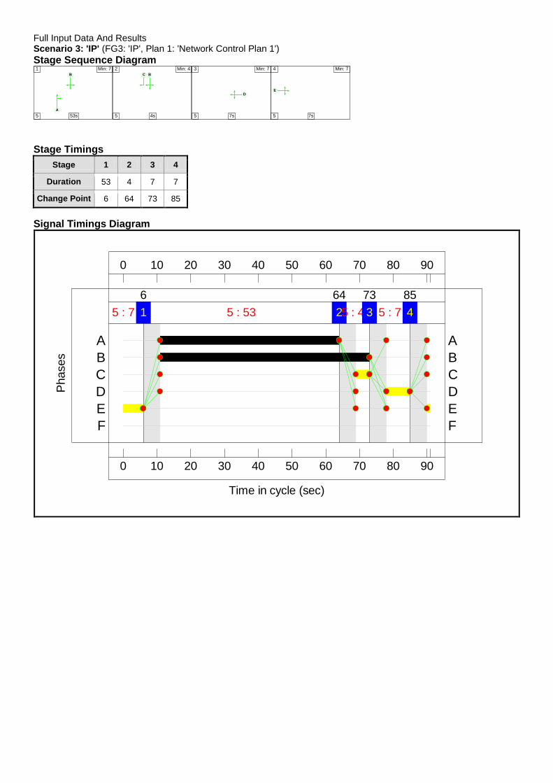
Full Input Data And Results Scenario 3: 'IP' (FG3: 'IP', Plan 1: 'Network Control Plan 1')
Stage Sequence Diagram
A
B
1 Min: 7
5 53s
BC
2 Min: 4
5 4s
D
3 Min: 7
5 7s
E
4 Min: 7
5 7s Stage Timings
Stage 1 2 3 4
Duration 53 4 7 7
Change Point 6 64 73 85
Signal Timings Diagram
0
0
10
10
20
20
30
30
40
40
50
50
60
60
70
70
80
80
90
90
Time in cycle (sec)
Phases
1 5 : 53
6
25 : 4
64
3 5 : 7
73
45 : 7
85
F F
E E
D D
C C
B B
A A

Full Input Data And Results
Network Results
Item Lane Description Lane Type
Controller Stream
Position In Filtered Route
Full Phase Arrow Phase
Num Greens
Total Green (s)
Arrow Green (s)
Demand Flow (pcu)
Sat Flow (pcu/Hr)
Capacity (pcu)
Deg Sat (%)
Network - - N/A - - - - - - - - 49.1%
Unnamed Junction
- - N/A - - - - - - - - 49.1%
1/1+1/2 Station Road
(Southbound) Left Ahead Right
U+O N/A N/A B C 1 62 4 483 1911:1798 1179+89 38.1 : 38.1%
2/1 Station Approach Right Left Ahead
U N/A N/A D 1 7 - 61 1875 165 37.0%
3/1 Station Road
(Northbound) Left O N/A N/A - - - - 74 1956 1402 5.3%
3/2+3/3 Station Road (Northbound) Ahead Right
U+O N/A N/A A 1 53 - 523 1885:1817 1024+71 47.8 : 47.8%
4/2+4/1 Waterside Drive Left Ahead Right
U N/A N/A E 1 7 - 105 1830:1799 161+53 49.1 : 49.1%
5/1 U N/A N/A - - - - 538 Inf Inf 0.0%
6/1 U N/A N/A - - - - 60 Inf Inf 0.0%
7/1 U N/A N/A - - - - 539 Inf Inf 0.0%
8/1 U N/A N/A - - - - 109 Inf Inf 0.0%

Full Input Data And Results
Item Arriving (pcu) Leaving (pcu)
Turners In Gaps (pcu)
Turners When Unopposed (pcu)
Turners In Intergreen (pcu)
Uniform Delay (pcuHr)
Rand + Oversat Delay (pcuHr)
Storage Area Uniform Delay (pcuHr)
Total Delay (pcuHr)
Av. Delay Per PCU (s/pcu)
Max. Back of Uniform Queue (pcu)
Rand + Oversat Queue (pcu)
Mean Max Queue (pcu)
Network - - 122 20 1 4.3 1.6 0.1 6.0 - - - -
Unnamed Junction
- - 122 20 1 4.3 1.6 0.1 6.0 - - - -
1/1+1/2 483 483 30 3 1 0.9 0.3 0.0 1.3 9.4 5.1 0.3 5.4
2/1 61 61 - - - 0.7 0.3 - 1.0 56.4 1.4 0.3 1.7
3/1 74 74 58 16 0 0.0 0.0 - 0.0 1.4 0.0 0.0 0.0
3/2+3/3 523 523 34 0 0 1.6 0.5 0.0 2.1 14.5 7.3 0.5 7.7
4/2+4/1 105 105 - - - 1.1 0.5 - 1.6 55.7 1.9 0.5 2.4
5/1 538 538 - - - 0.0 0.0 - 0.0 0.0 0.0 0.0 0.0
6/1 60 60 - - - 0.0 0.0 - 0.0 0.0 0.0 0.0 0.0
7/1 539 539 - - - 0.0 0.0 - 0.0 0.0 0.0 0.0 0.0
8/1 109 109 - - - 0.0 0.0 - 0.0 0.0 0.0 0.0 0.0
C1 PRC for Signalled Lanes (%): 83.3 Total Delay for Signalled Lanes (pcuHr): 5.95 Cycle Time (s): 91 PRC Over All Lanes (%): 83.3 Total Delay Over All Lanes(pcuHr): 5.97

Full Input Data And Results Scenario 4: 'AM 2018' (FG4: 'AM 2018', Plan 1: 'Network Control Plan 1')
Stage Sequence Diagram
A
B
1 Min: 7
5 40s
BC
2 Min: 4
5 7s
D
3 Min: 7
5 9s
E
4 Min: 7
5 14s Stage Timings
Stage 1 2 3 4
Duration 40 7 9 14
Change Point 0 45 57 71
Signal Timings Diagram
0
0
10
10
20
20
30
30
40
40
50
50
60
60
70
70
80
80
90
90
Time in cycle (sec)
Phases
1 5 : 40
0
2 5 : 7
45
3 5 : 9
57
4 5 : 14
71
F F
E E
D D
C C
B B
A A

Full Input Data And Results
Network Results
Item Lane Description Lane Type
Controller Stream
Position In Filtered Route
Full Phase Arrow Phase
Num Greens
Total Green (s)
Arrow Green (s)
Demand Flow (pcu)
Sat Flow (pcu/Hr)
Capacity (pcu)
Deg Sat (%)
Network - - N/A - - - - - - - - 63.9%
Unnamed Junction
- - N/A - - - - - - - - 63.9%
1/1+1/2 Station Road
(Southbound) Left Ahead Right
U+O N/A N/A B C 1 52 7 660 1911:1798 917+116 63.9 : 63.9%
2/1 Station Approach Right Left Ahead
U N/A N/A D 1 9 - 101 1878 209 48.4%
3/1 Station Road
(Northbound) Left O N/A N/A - - - - 151 1956 1356 11.1%
3/2+3/3 Station Road (Northbound) Ahead Right
U+O N/A N/A A 1 40 - 528 1885:1817 751+117 60.8 : 60.8%
4/2+4/1 Waterside Drive Left Ahead Right
U N/A N/A E 1 14 - 114 1830:1808 293+153 25.6 : 25.6%
5/1 U N/A N/A - - - - 514 Inf Inf 0.0%
6/1 U N/A N/A - - - - 106 Inf Inf 0.0%
7/1 U N/A N/A - - - - 705 Inf Inf 0.0%
8/1 U N/A N/A - - - - 229 Inf Inf 0.0%

Full Input Data And Results
Item Arriving (pcu) Leaving (pcu)
Turners In Gaps (pcu)
Turners When Unopposed (pcu)
Turners In Intergreen (pcu)
Uniform Delay (pcuHr)
Rand + Oversat Delay (pcuHr)
Storage Area Uniform Delay (pcuHr)
Total Delay (pcuHr)
Av. Delay Per PCU (s/pcu)
Max. Back of Uniform Queue (pcu)
Rand + Oversat Queue (pcu)
Mean Max Queue (pcu)
Network - - 240 54 2 7.3 2.4 0.4 10.1 - - - -
Unnamed Junction
- - 240 54 2 7.3 2.4 0.4 10.1 - - - -
1/1+1/2 660 660 63 9 2 2.6 0.9 0.1 3.6 19.6 10.9 0.9 11.8
2/1 101 101 - - - 1.1 0.5 - 1.5 54.2 2.4 0.5 2.8
3/1 151 151 106 45 0 0.0 0.1 - 0.1 1.5 0.0 0.1 0.1
3/2+3/3 528 528 71 0 0 2.7 0.8 0.2 3.7 25.0 9.2 0.8 10.0
4/2+4/1 114 114 - - - 1.0 0.2 - 1.2 37.8 1.6 0.2 1.8
5/1 514 514 - - - 0.0 0.0 - 0.0 0.0 0.0 0.0 0.0
6/1 106 106 - - - 0.0 0.0 - 0.0 0.0 0.0 0.0 0.0
7/1 705 705 - - - 0.0 0.0 - 0.0 0.0 0.0 0.0 0.0
8/1 229 229 - - - 0.0 0.0 - 0.0 0.0 0.0 0.0 0.0
C1 PRC for Signalled Lanes (%): 40.9 Total Delay for Signalled Lanes (pcuHr): 9.99 Cycle Time (s): 90 PRC Over All Lanes (%): 40.9 Total Delay Over All Lanes(pcuHr): 10.05

Full Input Data And Results Scenario 5: 'PM 2018' (FG5: 'PM 2018', Plan 1: 'Network Control Plan 1')
Stage Sequence Diagram
A
B
1 Min: 7
5 40s
BC
2 Min: 4
5 7s
D
3 Min: 7
5 12s
E
4 Min: 7
5 12s Stage Timings
Stage 1 2 3 4
Duration 40 7 12 12
Change Point 6 51 63 80
Signal Timings Diagram
0
0
10
10
20
20
30
30
40
40
50
50
60
60
70
70
80
80
90
90
Time in cycle (sec)
Phases
1 5 : 40
6
2 5 : 7
51
3 5 : 12
63
4 5 : 12
80
F F
E E
D D
C C
B B
A A

Full Input Data And Results
Network Results
Item Lane Description Lane Type
Controller Stream
Position In Filtered Route
Full Phase Arrow Phase
Num Greens
Total Green (s)
Arrow Green (s)
Demand Flow (pcu)
Sat Flow (pcu/Hr)
Capacity (pcu)
Deg Sat (%)
Network - - N/A - - - - - - - - 66.6%
Unnamed Junction
- - N/A - - - - - - - - 66.6%
1/1+1/2 Station Road
(Southbound) Left Ahead Right
U+O N/A N/A B C 1 52 7 509 1910:1798 1017+37 48.3 : 48.3%
2/1 Station Approach Right Left Ahead
U N/A N/A D 1 12 - 127 1878 268 47.3%
3/1 Station Road
(Northbound) Left O N/A N/A - - - - 74 1956 1413 5.2%
3/2+3/3 Station Road (Northbound) Ahead Right
U+O N/A N/A A 1 40 - 553 1885:1817 754+77 66.6 : 66.6%
4/2+4/1 Waterside Drive Left Ahead Right
U N/A N/A E 1 12 - 227 1830:1796 261+148 55.5 : 55.5%
5/1 U N/A N/A - - - - 627 Inf Inf 0.0%
6/1 U N/A N/A - - - - 85 Inf Inf 0.0%
7/1 U N/A N/A - - - - 680 Inf Inf 0.0%
8/1 U N/A N/A - - - - 98 Inf Inf 0.0%

Full Input Data And Results
Item Arriving (pcu) Leaving (pcu)
Turners In Gaps (pcu)
Turners When Unopposed (pcu)
Turners In Intergreen (pcu)
Uniform Delay (pcuHr)
Rand + Oversat Delay (pcuHr)
Storage Area Uniform Delay (pcuHr)
Total Delay (pcuHr)
Av. Delay Per PCU (s/pcu)
Max. Back of Uniform Queue (pcu)
Rand + Oversat Queue (pcu)
Mean Max Queue (pcu)
Network - - 120 23 0 8.4 2.5 0.1 11.0 - - - -
Unnamed Junction
- - 120 23 0 8.4 2.5 0.1 11.0 - - - -
1/1+1/2 509 509 15 2 0 1.8 0.5 0.0 2.3 16.0 7.6 0.5 8.1
2/1 127 127 - - - 1.3 0.4 - 1.7 48.5 2.9 0.4 3.4
3/1 74 74 54 20 0 0.0 0.0 - 0.0 1.3 0.0 0.0 0.0
3/2+3/3 553 553 51 0 0 3.1 1.0 0.1 4.2 27.1 10.5 1.0 11.5
4/2+4/1 227 227 - - - 2.3 0.6 - 2.9 45.7 3.4 0.6 4.0
5/1 627 627 - - - 0.0 0.0 - 0.0 0.0 0.0 0.0 0.0
6/1 85 85 - - - 0.0 0.0 - 0.0 0.0 0.0 0.0 0.0
7/1 680 680 - - - 0.0 0.0 - 0.0 0.0 0.0 0.0 0.0
8/1 98 98 - - - 0.0 0.0 - 0.0 0.0 0.0 0.0 0.0
C1 PRC for Signalled Lanes (%): 35.2 Total Delay for Signalled Lanes (pcuHr): 11.01 Cycle Time (s): 91 PRC Over All Lanes (%): 35.2 Total Delay Over All Lanes(pcuHr): 11.03

Full Input Data And Results Scenario 6: 'IP 2018' (FG6: 'IP 2018', Plan 1: 'Network Control Plan 1')
Stage Sequence Diagram
A
B
1 Min: 7
5 53s
BC
2 Min: 4
5 4s
D
3 Min: 7
5 7s
E
4 Min: 7
5 7s Stage Timings
Stage 1 2 3 4
Duration 53 4 7 7
Change Point 6 64 73 85
Signal Timings Diagram
0
0
10
10
20
20
30
30
40
40
50
50
60
60
70
70
80
80
90
90
Time in cycle (sec)
Phases
1 5 : 53
6
25 : 4
64
3 5 : 7
73
45 : 7
85
F F
E E
D D
C C
B B
A A

Full Input Data And Results
Network Results
Item Lane Description Lane Type
Controller Stream
Position In Filtered Route
Full Phase Arrow Phase
Num Greens
Total Green (s)
Arrow Green (s)
Demand Flow (pcu)
Sat Flow (pcu/Hr)
Capacity (pcu)
Deg Sat (%)
Network - - N/A - - - - - - - - 50.3%
Unnamed Junction
- - N/A - - - - - - - - 50.3%
1/1+1/2 Station Road
(Southbound) Left Ahead Right
U+O N/A N/A B C 1 62 4 496 1911:1798 1178+89 39.1 : 39.1%
2/1 Station Approach Right Left Ahead
U N/A N/A D 1 7 - 63 1875 165 38.2%
3/1 Station Road
(Northbound) Left O N/A N/A - - - - 76 1956 1401 5.4%
3/2+3/3 Station Road (Northbound) Ahead Right
U+O N/A N/A A 1 53 - 537 1885:1817 1024+71 49.0 : 49.0%
4/2+4/1 Waterside Drive Left Ahead Right
U N/A N/A E 1 7 - 108 1830:1798 161+54 50.3 : 50.3%
5/1 U N/A N/A - - - - 553 Inf Inf 0.0%
6/1 U N/A N/A - - - - 62 Inf Inf 0.0%
7/1 U N/A N/A - - - - 553 Inf Inf 0.0%
8/1 U N/A N/A - - - - 112 Inf Inf 0.0%

Full Input Data And Results
Item Arriving (pcu) Leaving (pcu)
Turners In Gaps (pcu)
Turners When Unopposed (pcu)
Turners In Intergreen (pcu)
Uniform Delay (pcuHr)
Rand + Oversat Delay (pcuHr)
Storage Area Uniform Delay (pcuHr)
Total Delay (pcuHr)
Av. Delay Per PCU (s/pcu)
Max. Back of Uniform Queue (pcu)
Rand + Oversat Queue (pcu)
Mean Max Queue (pcu)
Network - - 125 20 1 4.5 1.6 0.1 6.2 - - - -
Unnamed Junction
- - 125 20 1 4.5 1.6 0.1 6.2 - - - -
1/1+1/2 496 496 31 3 1 0.9 0.3 0.0 1.3 9.5 5.4 0.3 5.7
2/1 63 63 - - - 0.7 0.3 - 1.0 56.8 1.5 0.3 1.8
3/1 76 76 59 17 0 0.0 0.0 - 0.0 1.4 0.0 0.0 0.0
3/2+3/3 537 537 35 0 0 1.7 0.5 0.0 2.2 14.6 7.6 0.5 8.1
4/2+4/1 108 108 - - - 1.2 0.5 - 1.7 56.1 1.9 0.5 2.4
5/1 553 553 - - - 0.0 0.0 - 0.0 0.0 0.0 0.0 0.0
6/1 62 62 - - - 0.0 0.0 - 0.0 0.0 0.0 0.0 0.0
7/1 553 553 - - - 0.0 0.0 - 0.0 0.0 0.0 0.0 0.0
8/1 112 112 - - - 0.0 0.0 - 0.0 0.0 0.0 0.0 0.0
C1 PRC for Signalled Lanes (%): 78.8 Total Delay for Signalled Lanes (pcuHr): 6.17 Cycle Time (s): 91 PRC Over All Lanes (%): 78.8 Total Delay Over All Lanes(pcuHr): 6.20

Full Input Data And Results Scenario 7: 'AM 2028' (FG7: 'AM 2028', Plan 1: 'Network Control Plan 1')
Stage Sequence Diagram
A
B
1 Min: 7
5 40s
BC
2 Min: 4
5 7s
D
3 Min: 7
5 9s
E
4 Min: 7
5 14s Stage Timings
Stage 1 2 3 4
Duration 40 7 9 14
Change Point 0 45 57 71
Signal Timings Diagram
0
0
10
10
20
20
30
30
40
40
50
50
60
60
70
70
80
80
90
90
Time in cycle (sec)
Phases
1 5 : 40
0
2 5 : 7
45
3 5 : 9
57
4 5 : 14
71
F F
E E
D D
C C
B B
A A

Full Input Data And Results
Network Results
Item Lane Description Lane Type
Controller Stream
Position In Filtered Route
Full Phase Arrow Phase
Num Greens
Total Green (s)
Arrow Green (s)
Demand Flow (pcu)
Sat Flow (pcu/Hr)
Capacity (pcu)
Deg Sat (%)
Network - - N/A - - - - - - - - 71.2%
Unnamed Junction
- - N/A - - - - - - - - 71.2%
1/1+1/2 Station Road
(Southbound) Left Ahead Right
U+O N/A N/A B C 1 52 7 736 1911:1798 918+115 71.2 : 71.2%
2/1 Station Approach Right Left Ahead
U N/A N/A D 1 9 - 112 1878 209 53.7%
3/1 Station Road
(Northbound) Left O N/A N/A - - - - 169 1956 1346 12.6%
3/2+3/3 Station Road (Northbound) Ahead Right
U+O N/A N/A A 1 40 - 590 1885:1817 752+116 68.0 : 68.0%
4/2+4/1 Waterside Drive Left Ahead Right
U N/A N/A E 1 14 - 127 1830:1809 293+155 28.3 : 28.3%
5/1 U N/A N/A - - - - 574 Inf Inf 0.0%
6/1 U N/A N/A - - - - 118 Inf Inf 0.0%
7/1 U N/A N/A - - - - 786 Inf Inf 0.0%
8/1 U N/A N/A - - - - 256 Inf Inf 0.0%

Full Input Data And Results
Item Arriving (pcu) Leaving (pcu)
Turners In Gaps (pcu)
Turners When Unopposed (pcu)
Turners In Intergreen (pcu)
Uniform Delay (pcuHr)
Rand + Oversat Delay (pcuHr)
Storage Area Uniform Delay (pcuHr)
Total Delay (pcuHr)
Av. Delay Per PCU (s/pcu)
Max. Back of Uniform Queue (pcu)
Rand + Oversat Queue (pcu)
Mean Max Queue (pcu)
Network - - 267 61 2 8.5 3.1 0.5 12.2 - - - -
Unnamed Junction
- - 267 61 2 8.5 3.1 0.5 12.2 - - - -
1/1+1/2 736 736 70 10 2 3.1 1.2 0.2 4.5 21.9 13.1 1.2 14.3
2/1 112 112 - - - 1.2 0.6 - 1.7 56.2 2.6 0.6 3.2
3/1 169 169 118 51 0 0.0 0.1 - 0.1 1.5 0.0 0.1 0.1
3/2+3/3 590 590 79 0 0 3.1 1.1 0.3 4.5 27.5 10.9 1.1 11.9
4/2+4/1 127 127 - - - 1.1 0.2 - 1.3 38.1 1.8 0.2 2.0
5/1 574 574 - - - 0.0 0.0 - 0.0 0.0 0.0 0.0 0.0
6/1 118 118 - - - 0.0 0.0 - 0.0 0.0 0.0 0.0 0.0
7/1 786 786 - - - 0.0 0.0 - 0.0 0.0 0.0 0.0 0.0
8/1 256 256 - - - 0.0 0.0 - 0.0 0.0 0.0 0.0 0.0
C1 PRC for Signalled Lanes (%): 26.4 Total Delay for Signalled Lanes (pcuHr): 12.08 Cycle Time (s): 90 PRC Over All Lanes (%): 26.4 Total Delay Over All Lanes(pcuHr): 12.15
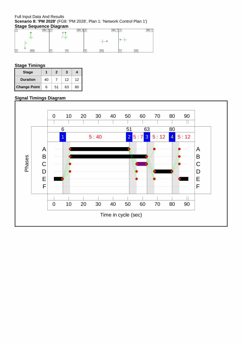
Full Input Data And Results Scenario 8: 'PM 2028' (FG8: 'PM 2028', Plan 1: 'Network Control Plan 1')
Stage Sequence Diagram
A
B
1 Min: 7
5 40s
BC
2 Min: 4
5 7s
D
3 Min: 7
5 12s
E
4 Min: 7
5 12s Stage Timings
Stage 1 2 3 4
Duration 40 7 12 12
Change Point 6 51 63 80
Signal Timings Diagram
0
0
10
10
20
20
30
30
40
40
50
50
60
60
70
70
80
80
90
90
Time in cycle (sec)
Phases
1 5 : 40
6
2 5 : 7
51
3 5 : 12
63
4 5 : 12
80
F F
E E
D D
C C
B B
A A
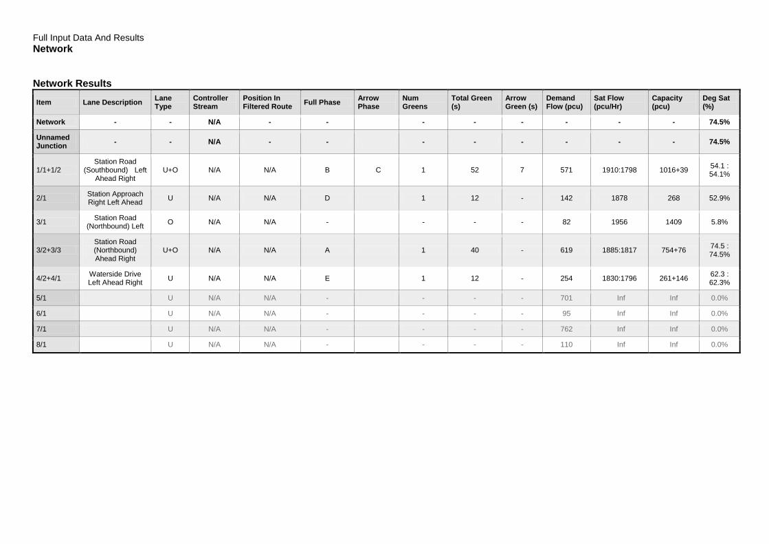
Full Input Data And Results
Network Network Results
Item Lane Description Lane Type
Controller Stream
Position In Filtered Route
Full Phase Arrow Phase
Num Greens
Total Green (s)
Arrow Green (s)
Demand Flow (pcu)
Sat Flow (pcu/Hr)
Capacity (pcu)
Deg Sat (%)
Network - - N/A - - - - - - - - 74.5%
Unnamed Junction
- - N/A - - - - - - - - 74.5%
1/1+1/2 Station Road
(Southbound) Left Ahead Right
U+O N/A N/A B C 1 52 7 571 1910:1798 1016+39 54.1 : 54.1%
2/1 Station Approach Right Left Ahead
U N/A N/A D 1 12 - 142 1878 268 52.9%
3/1 Station Road
(Northbound) Left O N/A N/A - - - - 82 1956 1409 5.8%
3/2+3/3 Station Road (Northbound) Ahead Right
U+O N/A N/A A 1 40 - 619 1885:1817 754+76 74.5 : 74.5%
4/2+4/1 Waterside Drive Left Ahead Right
U N/A N/A E 1 12 - 254 1830:1796 261+146 62.3 : 62.3%
5/1 U N/A N/A - - - - 701 Inf Inf 0.0%
6/1 U N/A N/A - - - - 95 Inf Inf 0.0%
7/1 U N/A N/A - - - - 762 Inf Inf 0.0%
8/1 U N/A N/A - - - - 110 Inf Inf 0.0%

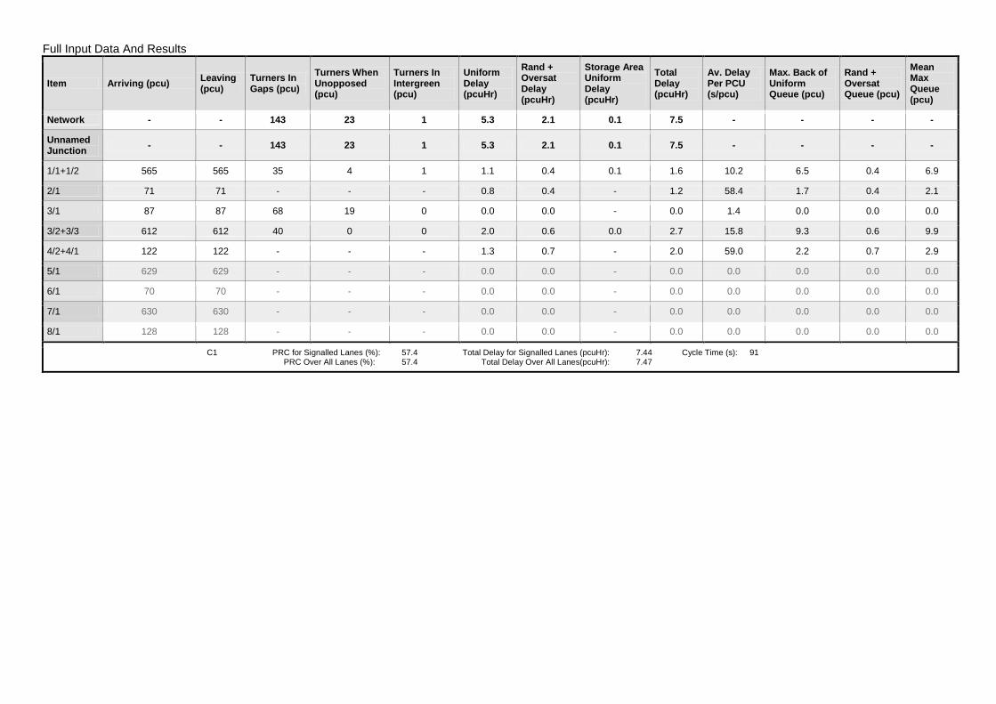
Full Input Data And Results
Item Arriving (pcu) Leaving (pcu)
Turners In Gaps (pcu)
Turners When Unopposed (pcu)
Turners In Intergreen (pcu)
Uniform Delay (pcuHr)
Rand + Oversat Delay (pcuHr)
Storage Area Uniform Delay (pcuHr)
Total Delay (pcuHr)
Av. Delay Per PCU (s/pcu)
Max. Back of Uniform Queue (pcu)
Rand + Oversat Queue (pcu)
Mean Max Queue (pcu)
Network - - 134 25 0 9.7 3.4 0.2 13.3 - - - -
Unnamed Junction
- - 134 25 0 9.7 3.4 0.2 13.3 - - - -
1/1+1/2 571 571 18 3 0 2.1 0.6 0.1 2.7 17.0 9.1 0.6 9.7
2/1 142 142 - - - 1.4 0.6 - 2.0 50.3 3.3 0.6 3.9
3/1 82 82 59 23 0 0.0 0.0 - 0.0 1.4 0.0 0.0 0.0
3/2+3/3 619 619 57 0 0 3.6 1.4 0.1 5.2 30.1 12.5 1.4 14.0
4/2+4/1 254 254 - - - 2.6 0.8 - 3.4 47.8 3.8 0.8 4.7
5/1 701 701 - - - 0.0 0.0 - 0.0 0.0 0.0 0.0 0.0
6/1 95 95 - - - 0.0 0.0 - 0.0 0.0 0.0 0.0 0.0
7/1 762 762 - - - 0.0 0.0 - 0.0 0.0 0.0 0.0 0.0
8/1 110 110 - - - 0.0 0.0 - 0.0 0.0 0.0 0.0 0.0
C1 PRC for Signalled Lanes (%): 20.8 Total Delay for Signalled Lanes (pcuHr): 13.24 Cycle Time (s): 91 PRC Over All Lanes (%): 20.8 Total Delay Over All Lanes(pcuHr): 13.27

Full Input Data And Results Scenario 9: 'IP 2028' (FG9: 'IP 2028', Plan 1: 'Network Control Plan 1')
Stage Sequence Diagram
A
B
1 Min: 7
5 53s
BC
2 Min: 4
5 4s
D
3 Min: 7
5 7s
E
4 Min: 7
5 7s Stage Timings
Stage 1 2 3 4
Duration 53 4 7 7
Change Point 6 64 73 85
Signal Timings Diagram
0
0
10
10
20
20
30
30
40
40
50
50
60
60
70
70
80
80
90
90
Time in cycle (sec)
Phases
1 5 : 53
6
25 : 4
64
3 5 : 7
73
45 : 7
85
F F
E E
D D
C C
B B
A A

Full Input Data And Results
Network Results
Item Lane Description Lane Type
Controller Stream
Position In Filtered Route
Full Phase Arrow Phase
Num Greens
Total Green (s)
Arrow Green (s)
Demand Flow (pcu)
Sat Flow (pcu/Hr)
Capacity (pcu)
Deg Sat (%)
Network - - N/A - - - - - - - - 57.2%
Unnamed Junction
- - N/A - - - - - - - - 57.2%
1/1+1/2 Station Road
(Southbound) Left Ahead Right
U+O N/A N/A B C 1 62 4 565 1911:1798 1178+90 44.6 : 44.6%
2/1 Station Approach Right Left Ahead
U N/A N/A D 1 7 - 71 1875 165 43.1%
3/1 Station Road
(Northbound) Left O N/A N/A - - - - 87 1956 1395 6.2%
3/2+3/3 Station Road (Northbound) Ahead Right
U+O N/A N/A A 1 53 - 612 1885:1817 1024+72 55.9 : 55.9%
4/2+4/1 Waterside Drive Left Ahead Right
U N/A N/A E 1 7 - 122 1830:1798 161+52 57.2 : 57.2%
5/1 U N/A N/A - - - - 629 Inf Inf 0.0%
6/1 U N/A N/A - - - - 70 Inf Inf 0.0%
7/1 U N/A N/A - - - - 630 Inf Inf 0.0%
8/1 U N/A N/A - - - - 128 Inf Inf 0.0%
Full Input Data And Results
Item Arriving (pcu) Leaving (pcu)
Turners In Gaps (pcu)
Turners When Unopposed (pcu)
Turners In Intergreen (pcu)
Uniform Delay (pcuHr)
Rand + Oversat Delay (pcuHr)
Storage Area Uniform Delay (pcuHr)
Total Delay (pcuHr)
Av. Delay Per PCU (s/pcu)
Max. Back of Uniform Queue (pcu)
Rand + Oversat Queue (pcu)
Mean Max Queue (pcu)
Network - - 143 23 1 5.3 2.1 0.1 7.5 - - - -
Unnamed Junction
- - 143 23 1 5.3 2.1 0.1 7.5 - - - -
1/1+1/2 565 565 35 4 1 1.1 0.4 0.1 1.6 10.2 6.5 0.4 6.9
2/1 71 71 - - - 0.8 0.4 - 1.2 58.4 1.7 0.4 2.1
3/1 87 87 68 19 0 0.0 0.0 - 0.0 1.4 0.0 0.0 0.0
3/2+3/3 612 612 40 0 0 2.0 0.6 0.0 2.7 15.8 9.3 0.6 9.9
4/2+4/1 122 122 - - - 1.3 0.7 - 2.0 59.0 2.2 0.7 2.9
5/1 629 629 - - - 0.0 0.0 - 0.0 0.0 0.0 0.0 0.0
6/1 70 70 - - - 0.0 0.0 - 0.0 0.0 0.0 0.0 0.0
7/1 630 630 - - - 0.0 0.0 - 0.0 0.0 0.0 0.0 0.0
8/1 128 128 - - - 0.0 0.0 - 0.0 0.0 0.0 0.0 0.0
C1 PRC for Signalled Lanes (%): 57.4 Total Delay for Signalled Lanes (pcuHr): 7.44 Cycle Time (s): 91 PRC Over All Lanes (%): 57.4 Total Delay Over All Lanes(pcuHr): 7.47

Langley Modelling and Economics v4
Technical note
Appendix C – Do Something LinSig outputs

Full Input Data And Results Full Input Data And Results User and Project Details
Project: Langley Station and Access Improvements
Title: Do Something models
Location:
File name: LIN-5149496-DS-002.lsg3x
Author:
Company:
Address:
Notes:
Network Layout Diagram
Unnamed Junction
Arm
1 -
Sta
tio
n R
oad
(S
out h
boun
d)
1
2
1/1
1/2
Arm 2 - Station Approach
1 2/1
Arm
3 - S
t atio
n R
oad
(North
bou
nd)
1 2
3
3/1
3/2
3/3
Arm 4 - Waterside Drive
1
2
4/1
4/2
Arm
5 -
15/1
Arm 6 -
16/1
Arm
7 -
17
/1
Arm 8 -
1 8/1
A
B
C
D

Full Input Data And Results
Phase Diagram
Phase Input Data
Phase Name Phase Type Assoc. Phase Street Min Cont Min
A Traffic 7 7
B Traffic 7 7
C Ind. Arrow B 4 4
D Traffic 7 7
E Traffic 7 7
F Dummy R/A 7 7
A
BC
D
E
F

Full Input Data And Results
Phase Intergreens Matrix
Starting Phase
Terminating Phase
A B C D E F
A - - 5 8 7 2
B - - - 5 8 2
C 8 - - 5 8 2
D 5 5 5 - 5 2
E 7 7 7 8 - 2
F 3 3 3 3 3 -
Phases in Stage
Stage No. Phases in Stage
1 A B
2 B C
3 D
4 E
Stage Diagram
Phase Delays
Term. Stage Start Stage Phase Type Value Cont value
There are no Phase Delays defined
Prohibited Stage Change
To Stage
From Stage
1 2 3 4
1 5 8 8
2 8 5 8
3 5 5 5
4 7 7 8
A
BC
DE
F
1 Min >= 7
A
BC
DE
F
2 Min >= 4
A
BC
DE
F
3 Min >= 7
A
BC
DE
F
4 Min >= 7

Full Input Data And Results Give-Way Lane Input Data
Junction: Unnamed Junction
Lane Movement
Max Flow when
Giving Way (PCU/Hr)
Min Flow when
Giving Way (PCU/Hr)
Opposing Lane
Opp. Lane Coeff.
Opp. Mvmnts.
Right Turn Storage (PCU)
Non-Blocking Storage (PCU)
RTF Right Turn Move up (s)
Max Turns in Intergreen
(PCU)
1/2 (Station Road (Southbound) )
8/1 (Right) 1439 0 3/2 1.09 All 2.00 - 0.50 2 2.00
3/1 (Station Road (Northbound))
8/1 (Left) 1439 0 1/2 1.09 All
- - - - - 2/1 1.09 To 8/1 (Ahead)
3/3 (Station Road (Northbound))
6/1 (Right) 1439 0 1/1 1.09 All 4.00 - 0.50 4 3.00

Full Input Data And Results Lane Input Data
Junction: Unnamed Junction
Lane Lane Type
Phases Start Disp.
End Disp.
Physical Length (PCU)
Sat Flow Type
Def User Saturation
Flow (PCU/Hr)
Lane Width
(m) Gradient
Nearside Lane
Turns Turning Radius
(m)
1/1 (Station Road (Southbound)
)
U B 2 3 60.0 Geom - 3.00 0.00 Y
Arm 6 Left
40.00
Arm 7 Ahead
Inf
1/2 (Station Road (Southbound)
)
O B C 2 3 3.5 Geom - 2.50 0.00 Y Arm 8 Right
40.00
2/1 (Station
Approach) U D 2 3 60.0 Geom - 3.25 0.00 Y
Arm 5 Right
40.00
Arm 7 Left
45.00
Arm 8 Ahead
Inf
3/1 (Station Road (Northbound))
O 2 3 6.1 Geom - 4.00 0.00 Y Arm 8 Left
50.00
3/2 (Station Road (Northbound))
U A 2 3 60.0 Geom - 2.70 0.00 Y Arm 5 Ahead
Inf
3/3 (Station Road (Northbound))
O A 2 3 3.8 Geom - 2.70 0.00 Y Arm 6 Right
40.00
4/1 (Waterside
Drive) U E 2 3 7.0 Geom - 2.70 0.00 Y
Arm 5 Left
30.00
Arm 6 Ahead
Inf
4/2 (Waterside
Drive) U E 2 3 60.0 Geom - 2.70 0.00 Y
Arm 7 Right
50.00
5/1 U 2 3 60.0 Inf - - - - - -
6/1 U 2 3 60.0 Inf - - - - - -
7/1 U 2 3 60.0 Inf - - - - - -
8/1 U 2 3 60.0 Inf - - - - - -
Scenario 4: 'AM 2018' (FG4: 'AM 2018', Plan 1: 'Network Control Plan 1')
Stage Sequence Diagram
A
B
1 Min: 7
7 50s
BC
2 Min: 4
5 4s
D
3 Min: 7
5 7s
E
4 Min: 7
5 7sA
B
1 Min: 7
7 56s
D
3 Min: 7
8 7s
E
4 Min: 7
5 7s

Full Input Data And Results
Stage Timings
Stage 1 2 3 4 1 3 4
Duration 50 4 7 7 56 7 7
Change Point 0 57 66 78 90 153 168
Signal Timings Diagram
0
0
10
10
20
20
30
30
40
40
50
50
60
60
70
70
80
80
90
90
100
100
110
110
120
120
130
130
140
140
150
150
160
160
170
170
180
180
Time in cycle (sec)
Pha
ses
1 7 : 50
0
2 5 : 4
57
3 5 : 7
66
4 5 : 7
78
1 7 : 56
90
3 8 : 7
153
4 5 : 7
168
F FE E
D D
C CB B
A A

Full Input Data And Results
Network Results
Item Lane Description Lane Type
Controller Stream
Position In Filtered Route
Full Phase Arrow Phase
Num Greens
Total Green (s)
Arrow Green (s)
Demand Flow (pcu)
Sat Flow (pcu/Hr)
Capacity (pcu)
Deg Sat (%)
Network - - N/A - - - - - - - - 60.5%
Unnamed Junction
- - N/A - - - - - - - - 60.5%
1/1+1/2 Station Road
(Southbound) Left Ahead Right
U+O N/A N/A B C 2 115 4 667 1911:1798 1057+146 55.4 : 55.4%
2/1 Station Approach Right Left Ahead
U N/A N/A D 2 14 - 101 1878 167 60.5%
3/1 Station Road
(Northbound) Left O N/A N/A - - - - 166 1956 1348 12.3%
3/2+3/3 Station Road (Northbound) Ahead Right
U+O N/A N/A A 2 106 - 528 1885:1817 995+155 45.9 : 45.9%
4/2+4/1 Waterside Drive Left Ahead Right
U N/A N/A E 2 14 - 114 1830:1808 163+85 46.1 : 46.1%
5/1 U N/A N/A - - - - 514 Inf Inf 0.0%
6/1 U N/A N/A - - - - 106 Inf Inf 0.0%
7/1 U N/A N/A - - - - 705 Inf Inf 0.0%
8/1 U N/A N/A - - - - 251 Inf Inf 0.0%

Full Input Data And Results
Item Arriving (pcu) Leaving (pcu)
Turners In Gaps (pcu)
Turners When Unopposed (pcu)
Turners In Intergreen (pcu)
Uniform Delay (pcuHr)
Rand + Oversat Delay (pcuHr)
Storage Area Uniform Delay (pcuHr)
Total Delay (pcuHr)
Av. Delay Per PCU (s/pcu)
Max. Back of Uniform Queue (pcu)
Rand + Oversat Queue (pcu)
Mean Max Queue (pcu)
Network - - 269 47 2 5.5 2.3 0.2 8.0 - - - -
Unnamed Junction
- - 269 47 2 5.5 2.3 0.2 8.0 - - - -
1/1+1/2 667 667 77 4 1 1.7 0.6 0.1 2.4 13.1 9.2 0.6 9.8
2/1 101 101 - - - 1.1 0.7 - 1.9 66.2 2.4 0.7 3.2
3/1 166 166 123 43 0 0.0 0.1 - 0.1 1.5 0.0 0.1 0.1
3/2+3/3 528 528 70 0 1 1.4 0.4 0.1 2.0 13.6 7.2 0.4 7.6
4/2+4/1 114 114 - - - 1.2 0.4 - 1.7 52.1 1.8 0.4 2.2
5/1 514 514 - - - 0.0 0.0 - 0.0 0.0 0.0 0.0 0.0
6/1 106 106 - - - 0.0 0.0 - 0.0 0.0 0.0 0.0 0.0
7/1 705 705 - - - 0.0 0.0 - 0.0 0.0 0.0 0.0 0.0
8/1 251 251 - - - 0.0 0.0 - 0.0 0.0 0.0 0.0 0.0
C1 PRC for Signalled Lanes (%): 48.8 Total Delay for Signalled Lanes (pcuHr): 7.92 Cycle Time (s): 180 PRC Over All Lanes (%): 48.8 Total Delay Over All Lanes(pcuHr): 7.99

Full Input Data And Results Scenario 5: 'PM 2018' (FG5: 'PM 2018', Plan 1: 'Network Control Plan 1')
Stage Sequence Diagram
Stage Timings
Stage 1 2 3 4 1 3 4
Duration 45 4 7 11 49 10 12
Change Point 6 58 67 79 95 151 169
Signal Timings Diagram
A
B
1 Min: 7
7 45s
BC
2 Min: 4
5 4s
D
3 Min: 7
5 7s
E
4 Min: 7
5 11sA
B
1 Min: 7
7 49s
D
3 Min: 7
8 10s
E
4 Min: 7
5 12s
0
0
10
10
20
20
30
30
40
40
50
50
60
60
70
70
80
80
90
90
100
100
110
110
120
120
130
130
140
140
150
150
160
160
170
170
180
180
Time in cycle (sec)
Pha
ses
1 7 : 45
6
2 5 : 4
58
3 5 : 7
67
4 5 : 11
79
1 7 : 49
95
3 8 : 10
151
4 5 : 12
169
F FE E
D D
C CB B
A A

Full Input Data And Results
Network Results
Item Lane Description Lane Type
Controller Stream
Position In Filtered Route
Full Phase Arrow Phase
Num Greens
Total Green (s)
Arrow Green (s)
Demand Flow (pcu)
Sat Flow (pcu/Hr)
Capacity (pcu)
Deg Sat (%)
Network - - N/A - - - - - - - - 64.1%
Unnamed Junction
- - N/A - - - - - - - - 64.1%
1/1+1/2 Station Road
(Southbound) Left Ahead Right
U+O N/A N/A B C 2 103 4 509 1910:1798 1049+38 46.8 : 46.8%
2/1 Station Approach Right Left Ahead
U N/A N/A D 2 17 - 127 1878 198 64.1%
3/1 Station Road
(Northbound) Left O N/A N/A - - - - 74 1956 1413 5.2%
3/2+3/3 Station Road (Northbound) Ahead Right
U+O N/A N/A A 2 94 - 553 1885:1817 914+93 54.9 : 54.9%
4/2+4/1 Waterside Drive Left Ahead Right
U N/A N/A E 2 23 - 250 1830:1796 254+143 63.0 : 63.0%
5/1 U N/A N/A - - - - 635 Inf Inf 0.0%
6/1 U N/A N/A - - - - 85 Inf Inf 0.0%
7/1 U N/A N/A - - - - 695 Inf Inf 0.0%
8/1 U N/A N/A - - - - 98 Inf Inf 0.0%

Full Input Data And Results
Item Arriving (pcu) Leaving (pcu)
Turners In Gaps (pcu)
Turners When Unopposed (pcu)
Turners In Intergreen (pcu)
Uniform Delay (pcuHr)
Rand + Oversat Delay (pcuHr)
Storage Area Uniform Delay (pcuHr)
Total Delay (pcuHr)
Av. Delay Per PCU (s/pcu)
Max. Back of Uniform Queue (pcu)
Rand + Oversat Queue (pcu)
Mean Max Queue (pcu)
Network - - 118 24 1 7.6 2.8 0.1 10.5 - - - -
Unnamed Junction
- - 118 24 1 7.6 2.8 0.1 10.5 - - - -
1/1+1/2 509 509 17 1 0 1.6 0.4 0.0 2.1 14.7 7.6 0.4 8.1
2/1 127 127 - - - 1.4 0.9 - 2.2 63.3 3.1 0.9 3.9
3/1 74 74 51 23 0 0.0 0.0 - 0.0 1.3 0.0 0.0 0.0
3/2+3/3 553 553 50 0 1 2.1 0.6 0.1 2.8 18.3 9.1 0.6 9.7
4/2+4/1 250 250 - - - 2.5 0.8 - 3.3 48.2 3.8 0.8 4.6
5/1 635 635 - - - 0.0 0.0 - 0.0 0.0 0.0 0.0 0.0
6/1 85 85 - - - 0.0 0.0 - 0.0 0.0 0.0 0.0 0.0
7/1 695 695 - - - 0.0 0.0 - 0.0 0.0 0.0 0.0 0.0
8/1 98 98 - - - 0.0 0.0 - 0.0 0.0 0.0 0.0 0.0
C1 PRC for Signalled Lanes (%): 40.5 Total Delay for Signalled Lanes (pcuHr): 10.47 Cycle Time (s): 180 PRC Over All Lanes (%): 40.5 Total Delay Over All Lanes(pcuHr): 10.50

Full Input Data And Results Scenario 6: 'IP 2018' (FG6: 'IP 2018', Plan 1: 'Network Control Plan 1')
Stage Sequence Diagram
Stage Timings
Stage 1 2 3 4 1 3 4
Duration 50 4 7 7 56 7 7
Change Point 6 63 72 84 96 159 174
Signal Timings Diagram
A
B
1 Min: 7
7 50s
BC
2 Min: 4
5 4s
D
3 Min: 7
5 7s
E
4 Min: 7
5 7sA
B
1 Min: 7
7 56s
D
3 Min: 7
8 7s
E
4 Min: 7
5 7s
0
0
10
10
20
20
30
30
40
40
50
50
60
60
70
70
80
80
90
90
100
100
110
110
120
120
130
130
140
140
150
150
160
160
170
170
180
180
Time in cycle (sec)
Pha
ses
1 7 : 50
6
2 5 : 4
63
3 5 : 7
72
4 5 : 7
84
1 7 : 56
96
3 8 : 7
159
45 : 7
174
F FE E
D D
C CB B
A A

Full Input Data And Results
Network Results
Item Lane Description Lane Type
Controller Stream
Position In Filtered Route
Full Phase Arrow Phase
Num Greens
Total Green (s)
Arrow Green (s)
Demand Flow (pcu)
Sat Flow (pcu/Hr)
Capacity (pcu)
Deg Sat (%)
Network - - N/A - - - - - - - - 49.8%
Unnamed Junction
- - N/A - - - - - - - - 49.8%
1/1+1/2 Station Road
(Southbound) Left Ahead Right
U+O N/A N/A B C 2 115 4 496 1911:1798 1133+86 40.7 : 40.7%
2/1 Station Approach Right Left Ahead
U N/A N/A D 2 14 - 63 1875 167 37.8%
3/1 Station Road
(Northbound) Left O N/A N/A - - - - 76 1956 1401 5.4%
3/2+3/3 Station Road (Northbound) Ahead Right
U+O N/A N/A A 2 106 - 537 1885:1817 1055+74 47.6 : 47.6%
4/2+4/1 Waterside Drive Left Ahead Right
U N/A N/A E 2 14 - 108 1830:1798 163+54 49.8 : 49.8%
5/1 U N/A N/A - - - - 553 Inf Inf 0.0%
6/1 U N/A N/A - - - - 62 Inf Inf 0.0%
7/1 U N/A N/A - - - - 553 Inf Inf 0.0%
8/1 U N/A N/A - - - - 112 Inf Inf 0.0%
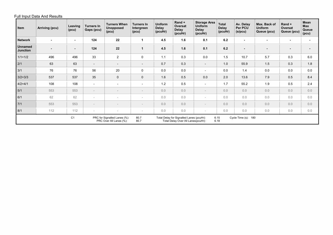
Full Input Data And Results
Item Arriving (pcu) Leaving (pcu)
Turners In Gaps (pcu)
Turners When Unopposed (pcu)
Turners In Intergreen (pcu)
Uniform Delay (pcuHr)
Rand + Oversat Delay (pcuHr)
Storage Area Uniform Delay (pcuHr)
Total Delay (pcuHr)
Av. Delay Per PCU (s/pcu)
Max. Back of Uniform Queue (pcu)
Rand + Oversat Queue (pcu)
Mean Max Queue (pcu)
Network - - 124 22 1 4.5 1.6 0.1 6.2 - - - -
Unnamed Junction
- - 124 22 1 4.5 1.6 0.1 6.2 - - - -
1/1+1/2 496 496 33 2 0 1.1 0.3 0.0 1.5 10.7 5.7 0.3 6.0
2/1 63 63 - - - 0.7 0.3 - 1.0 55.9 1.5 0.3 1.8
3/1 76 76 56 20 0 0.0 0.0 - 0.0 1.4 0.0 0.0 0.0
3/2+3/3 537 537 35 0 0 1.6 0.5 0.0 2.0 13.6 7.9 0.5 8.4
4/2+4/1 108 108 - - - 1.2 0.5 - 1.7 55.2 1.9 0.5 2.4
5/1 553 553 - - - 0.0 0.0 - 0.0 0.0 0.0 0.0 0.0
6/1 62 62 - - - 0.0 0.0 - 0.0 0.0 0.0 0.0 0.0
7/1 553 553 - - - 0.0 0.0 - 0.0 0.0 0.0 0.0 0.0
8/1 112 112 - - - 0.0 0.0 - 0.0 0.0 0.0 0.0 0.0
C1 PRC for Signalled Lanes (%): 80.7 Total Delay for Signalled Lanes (pcuHr): 6.15 Cycle Time (s): 180 PRC Over All Lanes (%): 80.7 Total Delay Over All Lanes(pcuHr): 6.18

Full Input Data And Results Scenario 7: 'AM 2028' (FG7: 'AM 2028', Plan 1: 'Network Control Plan 1')
Stage Sequence Diagram
Stage Timings
Stage 1 2 3 4 1 3 4
Duration 50 4 7 7 56 7 7
Change Point 0 57 66 78 90 153 168
Signal Timings Diagram
A
B
1 Min: 7
7 50s
BC
2 Min: 4
5 4s
D
3 Min: 7
5 7s
E
4 Min: 7
5 7sA
B
1 Min: 7
7 56s
D
3 Min: 7
8 7s
E
4 Min: 7
5 7s
0
0
10
10
20
20
30
30
40
40
50
50
60
60
70
70
80
80
90
90
100
100
110
110
120
120
130
130
140
140
150
150
160
160
170
170
180
180
Time in cycle (sec)
Pha
ses
1 7 : 50
0
2 5 : 4
57
3 5 : 7
66
4 5 : 7
78
1 7 : 56
90
3 8 : 7
153
4 5 : 7
168
F FE E
D D
C CB B
A A

Full Input Data And Results
Network Results
Item Lane Description Lane Type
Controller Stream
Position In Filtered Route
Full Phase Arrow Phase
Num Greens
Total Green (s)
Arrow Green (s)
Demand Flow (pcu)
Sat Flow (pcu/Hr)
Capacity (pcu)
Deg Sat (%)
Network - - N/A - - - - - - - - 67.1%
Unnamed Junction
- - N/A - - - - - - - - 67.1%
1/1+1/2 Station Road
(Southbound) Left Ahead Right
U+O N/A N/A B C 2 115 4 744 1911:1798 1058+146 61.8 : 61.8%
2/1 Station Approach Right Left Ahead
U N/A N/A D 2 14 - 112 1878 167 67.1%
3/1 Station Road
(Northbound) Left O N/A N/A - - - - 185 1956 1338 13.8%
3/2+3/3 Station Road (Northbound) Ahead Right
U+O N/A N/A A 2 106 - 590 1885:1817 995+154 51.3 : 51.3%
4/2+4/1 Waterside Drive Left Ahead Right
U N/A N/A E 2 14 - 127 1830:1809 163+86 51.0 : 51.0%
5/1 U N/A N/A - - - - 574 Inf Inf 0.0%
6/1 U N/A N/A - - - - 118 Inf Inf 0.0%
7/1 U N/A N/A - - - - 786 Inf Inf 0.0%
8/1 U N/A N/A - - - - 280 Inf Inf 0.0%

Full Input Data And Results
Item Arriving (pcu) Leaving (pcu)
Turners In Gaps (pcu)
Turners When Unopposed (pcu)
Turners In Intergreen (pcu)
Uniform Delay (pcuHr)
Rand + Oversat Delay (pcuHr)
Storage Area Uniform Delay (pcuHr)
Total Delay (pcuHr)
Av. Delay Per PCU (s/pcu)
Max. Back of Uniform Queue (pcu)
Rand + Oversat Queue (pcu)
Mean Max Queue (pcu)
Network - - 300 52 2 6.3 2.9 0.3 9.5 - - - -
Unnamed Junction
- - 300 52 2 6.3 2.9 0.3 9.5 - - - -
1/1+1/2 744 744 85 4 1 2.0 0.8 0.1 3.0 14.3 10.9 0.8 11.7
2/1 112 112 - - - 1.2 1.0 - 2.2 71.4 2.7 1.0 3.7
3/1 185 185 137 48 0 0.0 0.1 - 0.1 1.6 0.0 0.1 0.1
3/2+3/3 590 590 78 0 1 1.7 0.5 0.2 2.4 14.6 8.4 0.5 9.0
4/2+4/1 127 127 - - - 1.4 0.5 - 1.9 53.5 2.0 0.5 2.5
5/1 574 574 - - - 0.0 0.0 - 0.0 0.0 0.0 0.0 0.0
6/1 118 118 - - - 0.0 0.0 - 0.0 0.0 0.0 0.0 0.0
7/1 786 786 - - - 0.0 0.0 - 0.0 0.0 0.0 0.0 0.0
8/1 280 280 - - - 0.0 0.0 - 0.0 0.0 0.0 0.0 0.0
C1 PRC for Signalled Lanes (%): 34.1 Total Delay for Signalled Lanes (pcuHr): 9.46 Cycle Time (s): 180 PRC Over All Lanes (%): 34.1 Total Delay Over All Lanes(pcuHr): 9.54
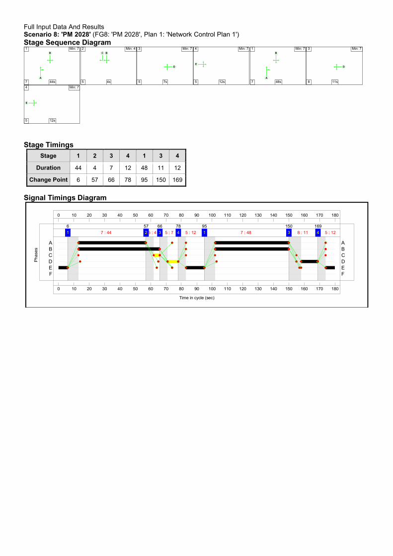
Full Input Data And Results Scenario 8: 'PM 2028' (FG8: 'PM 2028', Plan 1: 'Network Control Plan 1')
Stage Sequence Diagram
Stage Timings
Stage 1 2 3 4 1 3 4
Duration 44 4 7 12 48 11 12
Change Point 6 57 66 78 95 150 169
Signal Timings Diagram
A
B
1 Min: 7
7 44s
BC
2 Min: 4
5 4s
D
3 Min: 7
5 7s
E
4 Min: 7
5 12sA
B
1 Min: 7
7 48s
D
3 Min: 7
8 11s
E
4 Min: 7
5 12s
0
0
10
10
20
20
30
30
40
40
50
50
60
60
70
70
80
80
90
90
100
100
110
110
120
120
130
130
140
140
150
150
160
160
170
170
180
180
Time in cycle (sec)
Pha
ses
1 7 : 44
6
2 5 : 4
57
3 5 : 7
66
4 5 : 12
78
1 7 : 48
95
3 8 : 11
150
4 5 : 12
169
F FE E
D D
C CB B
A A

Full Input Data And Results
Network Results
Item Lane Description Lane Type
Controller Stream
Position In Filtered Route
Full Phase Arrow Phase
Num Greens
Total Green (s)
Arrow Green (s)
Demand Flow (pcu)
Sat Flow (pcu/Hr)
Capacity (pcu)
Deg Sat (%)
Network - - N/A - - - - - - - - 68.1%
Unnamed Junction
- - N/A - - - - - - - - 68.1%
1/1+1/2 Station Road
(Southbound) Left Ahead Right
U+O N/A N/A B C 2 101 4 571 1910:1798 1027+39 53.5 : 53.5%
2/1 Station Approach Right Left Ahead
U N/A N/A D 2 18 - 142 1878 209 68.1%
3/1 Station Road
(Northbound) Left O N/A N/A - - - - 82 1956 1409 5.8%
3/2+3/3 Station Road (Northbound) Ahead Right
U+O N/A N/A A 2 92 - 619 1885:1817 895+91 62.8 : 62.8%
4/2+4/1 Waterside Drive Left Ahead Right
U N/A N/A E 2 24 - 280 1830:1796 264+149 67.7 : 67.7%
5/1 U N/A N/A - - - - 711 Inf Inf 0.0%
6/1 U N/A N/A - - - - 95 Inf Inf 0.0%
7/1 U N/A N/A - - - - 778 Inf Inf 0.0%
8/1 U N/A N/A - - - - 110 Inf Inf 0.0%

Full Input Data And Results
Item Arriving (pcu) Leaving (pcu)
Turners In Gaps (pcu)
Turners When Unopposed (pcu)
Turners In Intergreen (pcu)
Uniform Delay (pcuHr)
Rand + Oversat Delay (pcuHr)
Storage Area Uniform Delay (pcuHr)
Total Delay (pcuHr)
Av. Delay Per PCU (s/pcu)
Max. Back of Uniform Queue (pcu)
Rand + Oversat Queue (pcu)
Mean Max Queue (pcu)
Network - - 132 27 1 8.9 3.5 0.1 12.6 - - - -
Unnamed Junction
- - 132 27 1 8.9 3.5 0.1 12.6 - - - -
1/1+1/2 571 571 20 1 0 2.0 0.6 0.0 2.6 16.4 9.2 0.6 9.8
2/1 142 142 - - - 1.5 1.0 - 2.6 64.7 3.4 1.0 4.5
3/1 82 82 56 26 0 0.0 0.0 - 0.0 1.4 0.0 0.0 0.0
3/2+3/3 619 619 56 0 1 2.6 0.8 0.1 3.6 20.8 11.0 0.8 11.8
4/2+4/1 280 280 - - - 2.8 1.0 - 3.8 49.2 4.3 1.0 5.3
5/1 711 711 - - - 0.0 0.0 - 0.0 0.0 0.0 0.0 0.0
6/1 95 95 - - - 0.0 0.0 - 0.0 0.0 0.0 0.0 0.0
7/1 778 778 - - - 0.0 0.0 - 0.0 0.0 0.0 0.0 0.0
8/1 110 110 - - - 0.0 0.0 - 0.0 0.0 0.0 0.0 0.0
C1 PRC for Signalled Lanes (%): 32.3 Total Delay for Signalled Lanes (pcuHr): 12.56 Cycle Time (s): 180 PRC Over All Lanes (%): 32.3 Total Delay Over All Lanes(pcuHr): 12.59

Full Input Data And Results Scenario 9: 'IP 2028' (FG9: 'IP 2028', Plan 1: 'Network Control Plan 1')
Stage Sequence Diagram
Stage Timings
Stage 1 2 3 4 1 3 4
Duration 50 4 7 7 56 7 7
Change Point 6 63 72 84 96 159 174
Signal Timings Diagram
A
B
1 Min: 7
7 50s
BC
2 Min: 4
5 4s
D
3 Min: 7
5 7s
E
4 Min: 7
5 7sA
B
1 Min: 7
7 56s
D
3 Min: 7
8 7s
E
4 Min: 7
5 7s
0
0
10
10
20
20
30
30
40
40
50
50
60
60
70
70
80
80
90
90
100
100
110
110
120
120
130
130
140
140
150
150
160
160
170
170
180
180
Time in cycle (sec)
Pha
ses
1 7 : 50
6
2 5 : 4
63
3 5 : 7
72
4 5 : 7
84
1 7 : 56
96
3 8 : 7
159
45 : 7
174
F FE E
D D
C CB B
A A
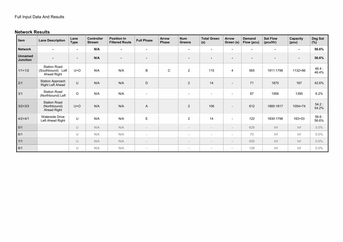
Full Input Data And Results
Network Results
Item Lane Description Lane Type
Controller Stream
Position In Filtered Route
Full Phase Arrow Phase
Num Greens
Total Green (s)
Arrow Green (s)
Demand Flow (pcu)
Sat Flow (pcu/Hr)
Capacity (pcu)
Deg Sat (%)
Network - - N/A - - - - - - - - 56.6%
Unnamed Junction
- - N/A - - - - - - - - 56.6%
1/1+1/2 Station Road
(Southbound) Left Ahead Right
U+O N/A N/A B C 2 115 4 565 1911:1798 1132+86 46.4 : 46.4%
2/1 Station Approach Right Left Ahead
U N/A N/A D 2 14 - 71 1875 167 42.6%
3/1 Station Road
(Northbound) Left O N/A N/A - - - - 87 1956 1395 6.2%
3/2+3/3 Station Road (Northbound) Ahead Right
U+O N/A N/A A 2 106 - 612 1885:1817 1054+74 54.2 : 54.2%
4/2+4/1 Waterside Drive Left Ahead Right
U N/A N/A E 2 14 - 122 1830:1798 163+53 56.6 : 56.6%
5/1 U N/A N/A - - - - 629 Inf Inf 0.0%
6/1 U N/A N/A - - - - 70 Inf Inf 0.0%
7/1 U N/A N/A - - - - 630 Inf Inf 0.0%
8/1 U N/A N/A - - - - 128 Inf Inf 0.0%

Full Input Data And Results
Item Arriving (pcu) Leaving (pcu)
Turners In Gaps (pcu)
Turners When Unopposed (pcu)
Turners In Intergreen (pcu)
Uniform Delay (pcuHr)
Rand + Oversat Delay (pcuHr)
Storage Area Uniform Delay (pcuHr)
Total Delay (pcuHr)
Av. Delay Per PCU (s/pcu)
Max. Back of Uniform Queue (pcu)
Rand + Oversat Queue (pcu)
Mean Max Queue (pcu)
Network - - 141 25 1 5.3 2.1 0.1 7.4 - - - -
Unnamed Junction
- - 141 25 1 5.3 2.1 0.1 7.4 - - - -
1/1+1/2 565 565 38 2 0 1.3 0.4 0.1 1.8 11.5 7.0 0.4 7.4
2/1 71 71 - - - 0.8 0.4 - 1.1 57.5 1.7 0.4 2.0
3/1 87 87 64 23 0 0.0 0.0 - 0.0 1.4 0.0 0.0 0.0
3/2+3/3 612 612 40 0 0 1.9 0.6 0.0 2.5 14.7 9.8 0.6 10.4
4/2+4/1 122 122 - - - 1.3 0.6 - 2.0 58.0 2.2 0.6 2.8
5/1 629 629 - - - 0.0 0.0 - 0.0 0.0 0.0 0.0 0.0
6/1 70 70 - - - 0.0 0.0 - 0.0 0.0 0.0 0.0 0.0
7/1 630 630 - - - 0.0 0.0 - 0.0 0.0 0.0 0.0 0.0
8/1 128 128 - - - 0.0 0.0 - 0.0 0.0 0.0 0.0 0.0
C1 PRC for Signalled Lanes (%): 59.1 Total Delay for Signalled Lanes (pcuHr): 7.40 Cycle Time (s): 180 PRC Over All Lanes (%): 59.1 Total Delay Over All Lanes(pcuHr): 7.43


