CMN; Reviewed:
SPOC 07/23/2014
Solution & Interoperability Test Lab Application Notes
©2014 Avaya Inc. All Rights Reserved.
1 of 50
BTNOASCS1K76SM
Avaya Solution & Interoperability Test Lab
Application Notes for Configuring Avaya Communication
Server 1000E R7.6 with Avaya Aura® Session Manager R6.3
to support BT Global Services NOAS SIP Trunk - Issue 1.0
Abstract
These Application Notes describe the steps to configure Session Initiation Protocol (SIP)
trunking between the BT Global Services NOAS SIP Trunk service and an Avaya SIP enabled
enterprise solution. The Avaya solution consists of Avaya Aura® Session Manager and Avaya
Communication Server 1000E. BT is a member of the DevConnect Service Provider program.
Information in these Application Notes has been obtained through DevConnect compliance
testing and additional technical discussions. Testing was conducted via the DevConnect
Program at the Avaya Solution and Interoperability Test Lab.
CMN; Reviewed:
SPOC 07/23/2014
Solution & Interoperability Test Lab Application Notes
©2014 Avaya Inc. All Rights Reserved.
2 of 50
BTNOASCS1K76SM
1. Introduction These Application Notes describe the steps required to configure Session Initiation Protocol
(SIP) trunking between BT NOAS SIP Trunk Service and an Avaya SIP enabled enterprise
solution. The Avaya solution consists of Avaya Aura® Session Manager and Avaya
Communication Server 1000E connected by TCP to the BT SIP Trunk Service. Customers using
this Avaya SIP-enabled enterprise solution with the BT SIP Trunk Service are able to place and
receive PSTN calls via a dedicated Internet connection and the SIP protocol. This converged
network solution is an alternative to traditional PSTN trunks. This approach normally results in
lower cost for the enterprise.
2. General Test Approach and Test Results The general test approach was to configure a simulated enterprise site using an Avaya SIP
telephony solution consisting of Avaya Aura®
Session Manager and Avaya Communication
Server 1000E. The enterprise site was configured to use the SIP Trunk Service provided by BT,
with all incoming and outgoing PSTN calls via the BT SIP Trunk Service.
DevConnect Compliance Testing is conducted jointly by Avaya and DevConnect members. The
jointly-defined test plan focuses on exercising APIs and/or standards-based interfaces pertinent
to the interoperability of the tested products and their functionalities. DevConnect Compliance
Testing is not intended to substitute full product performance or feature testing performed by
DevConnect members, nor is it to be construed as an endorsement by Avaya of the suitability or
completeness of a DevConnect member’s solution.
2.1. Interoperability Compliance Testing
The interoperability test included the following:
Incoming calls to the enterprise site from the PSTN were routed to the DID numbers
assigned by BT. Incoming PSTN calls were terminated on Digital, Analog and Unistim
telephones at the enterprise site.
Outgoing calls from the enterprise site were completed via BT to PSTN telephones.
Outgoing calls from the enterprise to the PSTN were made from Digital, Analog and
Unistim telephones.
Calls were made using G.729A, and G.711A codecs.
Fax calls to/from a Group 3 fax machine to a PSTN connected fax machine using the
T.38 transmission mode.
DTMF transmission using RFC 2833 with successful IVR menu progression.
User features such as hold and resume, transfer, conference, call forwarding, etc.
Caller ID Presentation and Caller ID Restriction.
Call coverage and call forwarding for endpoints at the enterprise site.
Transmission and response of SIP OPTIONS messages sent by BT requiring an Avaya
response, and SIP OPTIONS sent by Avaya requiring a BT response.
CMN; Reviewed:
SPOC 07/23/2014
Solution & Interoperability Test Lab Application Notes
©2014 Avaya Inc. All Rights Reserved.
3 of 50
BTNOASCS1K76SM
2.2. Test Results
Interoperability testing of the sample configuration was completed with successful results for the
BT SIP Trunk Service with the following observations:
During testing it was observed that when BT NOAS initiates a call-hold, BT NOAS send
a reINVITE with the attribute “SendOnly” in the SDP. The CS1000E correctly responds
with 200OK with the attribute “RecvOnly” in the SDP and RTP is only sent in one
direction, in this case from BT NOAS to the Avaya 11xx/12xx series SIP Phoneset.
However, once call-hold is initiated, RTCP is just sent in one direction from BT NOAS
to the 11xx/12xx series SIP Phoneset. Avaya 11xx/12xx series SIP phonesets do not send
RTCP packets when BT NOAS initiated call-hold using the Media attribute “SendOnly”
in the SDP. BT NOAS expect to receive RTCP from the 11xx/12xx series SIP Phonesets
and have 25 second RTCP timers configured on their SIP MGW. As BT NOAS don’t
receive any RTCP from the 11xx/12xx SIP Phoneset, after 25 seconds, BT NOAS issue a
BYE and the call is torn down. There is currently no fix planned for this issue.
Avaya 11xx and 12xx Series phonesets running SIP firmware are not supported.
As BT does not support SIP UPDATE, the CS1000E default configuration will not allow a
blind transfer to be executed if the parties involved do not support the SIP UPDATE method.
With the installation of plugin 501 on the CS1000E, the blind transfer will be allowed and the
call will be completed. The limitation of this plugin is that no ringback is provided to the
originator of the call for the duration that the destination set is ringing. In addition to plugin
501, it is required that VTRK SU version “cs1000-vtrk-7.65.17.16-15.i386.000.ntl” or
higher be used on all SSG signaling servers to ensure proper operation of the blind transfer
feature. The use of plugin 501 does not restrict the use of the SIP UPDATE method of blind
transfer to other parties that do happen to support the UPATE method, but rather extend
support to those parties that do not
Inbound call hold and resume from PSTN was not tested as the PSTN was unable to
initiate the call-hold due to their environment set-up.
PSTN called party hangup during an active call did not cause the call to drop. The
Communication Server 1000E caller must hangup first, or wait for the PSTN T2ISUP
timer to expire.
Calls to/from SMC 3456 soft clients using unsupported codecs failed, most likely
because the call server was unable to determine the set capabilities, and the SMC 3456
not correctly handling the calls.
No inbound toll free numbers were tested as none were available from the Service
Provider
No Emergency Services numbers tested as test calls to these numbers should be pre-
arranged with the Operator
All unwanted MIME was stripped on outbound calls using the Adaptation Module in
Session Manager
2.3. Support
For technical support on BT products please use the following web link.
http://btbusiness.custhelp.com/app/contact
CMN; Reviewed:
SPOC 07/23/2014
Solution & Interoperability Test Lab Application Notes
©2014 Avaya Inc. All Rights Reserved.
4 of 50
BTNOASCS1K76SM
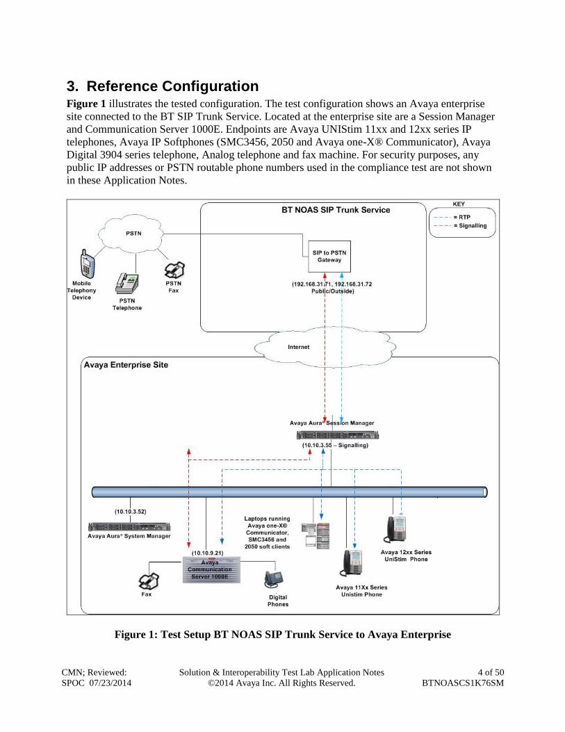
3. Reference Configuration Figure 1 illustrates the tested configuration. The test configuration shows an Avaya enterprise
site connected to the BT SIP Trunk Service. Located at the enterprise site are a Session Manager
and Communication Server 1000E. Endpoints are Avaya UNIStim 11xx and 12xx series IP
telephones, Avaya IP Softphones (SMC3456, 2050 and Avaya one-X® Communicator), Avaya
Digital 3904 series telephone, Analog telephone and fax machine. For security purposes, any
public IP addresses or PSTN routable phone numbers used in the compliance test are not shown
in these Application Notes.
Figure 1: Test Setup BT NOAS SIP Trunk Service to Avaya Enterprise
CMN; Reviewed:
SPOC 07/23/2014
Solution & Interoperability Test Lab Application Notes
©2014 Avaya Inc. All Rights Reserved.
5 of 50
BTNOASCS1K76SM
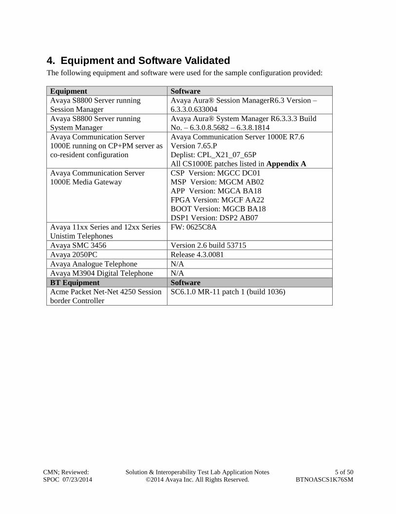
4. Equipment and Software Validated The following equipment and software were used for the sample configuration provided:
Equipment Software
Avaya S8800 Server running
Session Manager
Avaya Aura® Session ManagerR6.3 Version –
6.3.3.0.633004
Avaya S8800 Server running
System Manager
Avaya Aura® System Manager R6.3.3.3 Build
No. – 6.3.0.8.5682 – 6.3.8.1814
Avaya Communication Server
1000E running on CP+PM server as
co-resident configuration
Avaya Communication Server 1000E R7.6
Version 7.65.P
Deplist: CPL_X21_07_65P
All CS1000E patches listed in Appendix A
Avaya Communication Server
1000E Media Gateway
CSP Version: MGCC DC01
MSP Version: MGCM AB02
APP Version: MGCA BA18
FPGA Version: MGCF AA22
BOOT Version: MGCB BA18
DSP1 Version: DSP2 AB07
Avaya 11xx Series and 12xx Series
Unistim Telephones
FW: 0625C8A
Avaya SMC 3456 Version 2.6 build 53715
Avaya 2050PC Release 4.3.0081
Avaya Analogue Telephone N/A
Avaya M3904 Digital Telephone N/A
BT Equipment Software
Acme Packet Net-Net 4250 Session
border Controller
SC6.1.0 MR-11 patch 1 (build 1036)
CMN; Reviewed:
SPOC 07/23/2014
Solution & Interoperability Test Lab Application Notes
©2014 Avaya Inc. All Rights Reserved.
6 of 50
BTNOASCS1K76SM
5. Configure Avaya Communication Server 1000E This section describes the steps required to configure the Avaya Communication Server 1000E
for SIP Trunking service and also the necessary configuration for terminals (digital, analog and
IP phones). SIP trunks are established between Communication Server 1000E and Session
Manager. These SIP trunks carry SIP Signaling associated with BT SIP Trunk Service. For
incoming calls, Session Manager receives SIP messages from the BT Global Services NOAS SIP
Trunk router, through which the BT Global Services NOAS SIP Trunk service directs incoming
SIP messages to Communication Server 1000E (see Figure 1). Once a SIP message arrives at
Communication Server 1000E, further incoming call treatment, such as incoming digit
translations and class of service restrictions may be performed. All outgoing calls to the PSTN
are processed within Communication Server 1000E and may be first subject to outbound features
such as route selection, digit manipulation and class of service restrictions. Once Communication
Server 1000E selects a SIP trunk, the SIP signaling is routed to Session Manager. Session
Manager directs the outbound SIP messages to the Avaya Enterprise router and on to the BT
network. Specific Communication Server 1000E configuration was performed using Element
Manager and the system terminal interface.
Specific CS1000E configuration was performed using Element Manager and the system terminal
interface. The general installation of the CS1000E, System Manager and Session Manager is
presumed to have been previously completed and is not discussed here. Configuration details
will be provided as required to draw attention to changes in default system configurations.
5.1. Logging into the Avaya Communication Server 1000E
Configuration on the CS1000E will be performed by using both an SSH Putty session and the
Avaya Unified Communications Management GUI.
Log in via SSH to the ELAN IP address of the Call Server using a user with correct privileges.
Once logged in, type csconsole, this will take the user into the vxworks shell of the call server.
Next type login, the user will then be asked to login with correct credentials. Once logged in, the
user can then progress to load any overlay.
Log in using the web based Avaya Unified Communications Management GUI. The Avaya
Unified Communications Management GUI may be launched directly via http://<ipaddress>
where the relevant <ipaddress> is the TLAN IP address of the CS1000E.
The following screen shows the login screen. Login with the appropriate credentials.
CMN; Reviewed:
SPOC 07/23/2014
Solution & Interoperability Test Lab Application Notes
©2014 Avaya Inc. All Rights Reserved.
7 of 50
BTNOASCS1K76SM
The Avaya Unified Communications Management Elements page will be used for configuration.
Click on the Element Name corresponding to CS1000E in the Element Type column. In the
abridged screen below, the user would click on the Element Name EM on cs1kvl9.
CMN; Reviewed:
SPOC 07/23/2014
Solution & Interoperability Test Lab Application Notes
©2014 Avaya Inc. All Rights Reserved.
8 of 50
BTNOASCS1K76SM
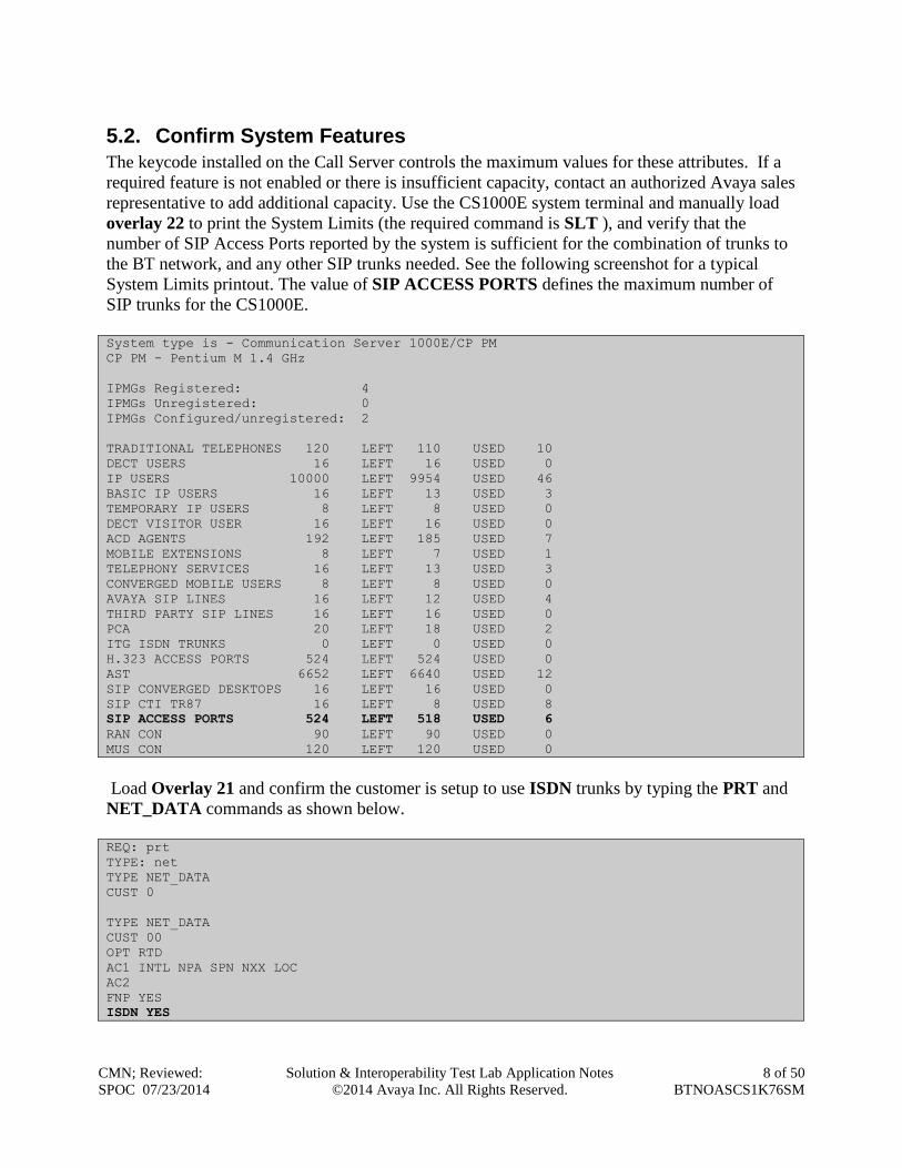
5.2. Confirm System Features
The keycode installed on the Call Server controls the maximum values for these attributes. If a
required feature is not enabled or there is insufficient capacity, contact an authorized Avaya sales
representative to add additional capacity. Use the CS1000E system terminal and manually load
overlay 22 to print the System Limits (the required command is SLT ), and verify that the
number of SIP Access Ports reported by the system is sufficient for the combination of trunks to
the BT network, and any other SIP trunks needed. See the following screenshot for a typical
System Limits printout. The value of SIP ACCESS PORTS defines the maximum number of
SIP trunks for the CS1000E.
System type is - Communication Server 1000E/CP PM
CP PM - Pentium M 1.4 GHz
IPMGs Registered: 4
IPMGs Unregistered: 0
IPMGs Configured/unregistered: 2
TRADITIONAL TELEPHONES 120 LEFT 110 USED 10
DECT USERS 16 LEFT 16 USED 0
IP USERS 10000 LEFT 9954 USED 46
BASIC IP USERS 16 LEFT 13 USED 3
TEMPORARY IP USERS 8 LEFT 8 USED 0
DECT VISITOR USER 16 LEFT 16 USED 0
ACD AGENTS 192 LEFT 185 USED 7
MOBILE EXTENSIONS 8 LEFT 7 USED 1
TELEPHONY SERVICES 16 LEFT 13 USED 3
CONVERGED MOBILE USERS 8 LEFT 8 USED 0
AVAYA SIP LINES 16 LEFT 12 USED 4
THIRD PARTY SIP LINES 16 LEFT 16 USED 0
PCA 20 LEFT 18 USED 2
ITG ISDN TRUNKS 0 LEFT 0 USED 0
H.323 ACCESS PORTS 524 LEFT 524 USED 0
AST 6652 LEFT 6640 USED 12
SIP CONVERGED DESKTOPS 16 LEFT 16 USED 0
SIP CTI TR87 16 LEFT 8 USED 8
SIP ACCESS PORTS 524 LEFT 518 USED 6
RAN CON 90 LEFT 90 USED 0
MUS CON 120 LEFT 120 USED 0
Load Overlay 21 and confirm the customer is setup to use ISDN trunks by typing the PRT and
NET_DATA commands as shown below.
REQ: prt
TYPE: net
TYPE NET_DATA
CUST 0
TYPE NET_DATA
CUST 00
OPT RTD
AC1 INTL NPA SPN NXX LOC
AC2
FNP YES
ISDN YES
CMN; Reviewed:
SPOC 07/23/2014
Solution & Interoperability Test Lab Application Notes
©2014 Avaya Inc. All Rights Reserved.
9 of 50
BTNOASCS1K76SM
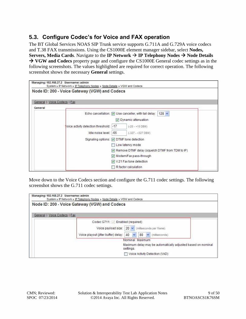
5.3. Configure Codec’s for Voice and FAX operation
The BT Global Services NOAS SIP Trunk service supports G.711A and G.729A voice codecs
and T.38 FAX transmissions. Using the CS1000E element manager sidebar, select Nodes,
Servers, Media Cards. Navigate to the IP Network IP Telephony Nodes Node Details
VGW and Codecs property page and configure the CS1000E General codec settings as in the
following screenshots. The values highlighted are required for correct operation. The following
screenshot shows the necessary General settings.
Move down to the Voice Codecs section and configure the G.711 codec settings. The following
screenshot shows the G.711 codec settings.
CMN; Reviewed:
SPOC 07/23/2014
Solution & Interoperability Test Lab Application Notes
©2014 Avaya Inc. All Rights Reserved.
10 of 50
BTNOASCS1K76SM
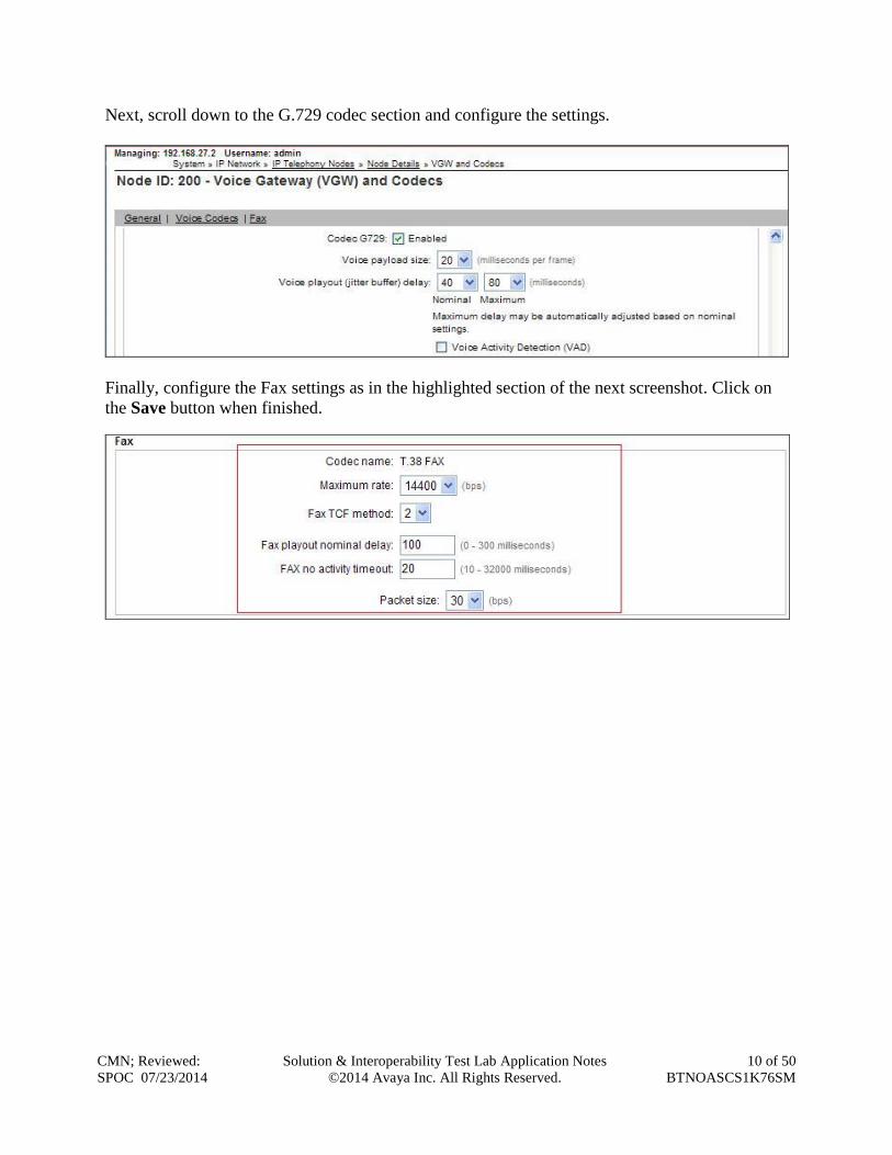
Next, scroll down to the G.729 codec section and configure the settings.
Finally, configure the Fax settings as in the highlighted section of the next screenshot. Click on
the Save button when finished.
CMN; Reviewed:
SPOC 07/23/2014
Solution & Interoperability Test Lab Application Notes
©2014 Avaya Inc. All Rights Reserved.
11 of 50
BTNOASCS1K76SM
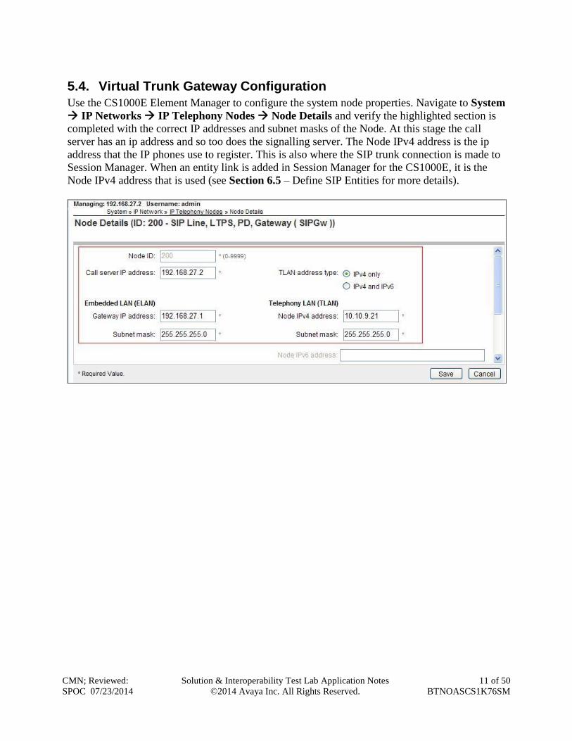
5.4. Virtual Trunk Gateway Configuration
Use the CS1000E Element Manager to configure the system node properties. Navigate to System
IP Networks IP Telephony Nodes Node Details and verify the highlighted section is
completed with the correct IP addresses and subnet masks of the Node. At this stage the call
server has an ip address and so too does the signalling server. The Node IPv4 address is the ip
address that the IP phones use to register. This is also where the SIP trunk connection is made to
Session Manager. When an entity link is added in Session Manager for the CS1000E, it is the
Node IPv4 address that is used (see Section 6.5 – Define SIP Entities for more details).
CMN; Reviewed:
SPOC 07/23/2014
Solution & Interoperability Test Lab Application Notes
©2014 Avaya Inc. All Rights Reserved.
12 of 50
BTNOASCS1K76SM
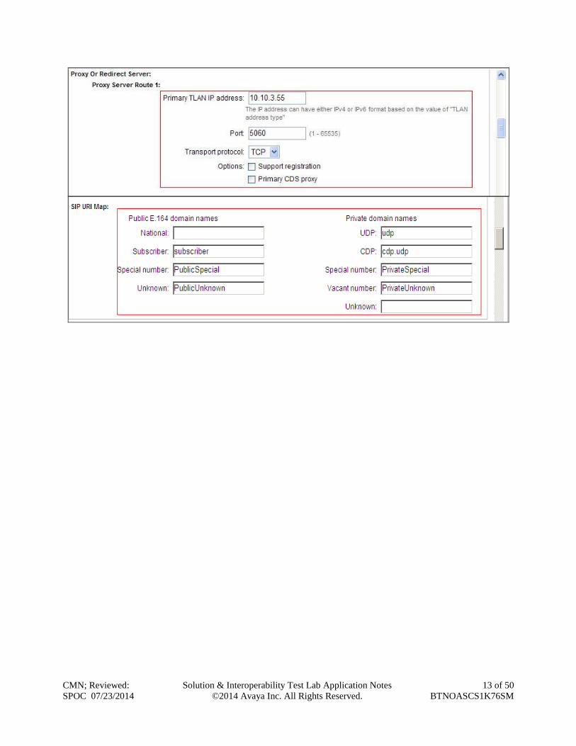
The next two screenshots show the SIP Virtual Trunk Gateway configuration. Navigate to
System IP Networks IP Telephony Nodes Node Details Gateway (SIPGW)
Virtual Trunk Configuration Details and fill in the highlighted areas with the relevant settings.
Vtrk gateway application: Provides option to select Gateway applications. The three
supported modes are SIP Gateway (SIPGw), H.323Gw, and SIPGw and H.323Gw
SIP domain name: The SIP Domain Name is the SIP Service Domain. The SIP Domain
Name configured in the Signaling Server properties must match the SIP Domain
configured in Session Manager, in this case avaya.com
Local SIP port: The Local SIP Port is the port on which the gateway listens. The default
value is 5060
Gateway endpoint name: This field cannot be left blank so a value is needed here. This
field is used when a Network Routing Server is used for registration of the endpoint. In
this network Session Manager is used so any value can be put in here as it will not be
used
Application node ID: This is a unique value that can be alphanumeric and is for the new
Node that is being created, in this case 200
Proxy or Redirect Server: Primary TLAN IP address is the Security Module IP address
of Session Manager. The Transport protocol used for SIP, in this case is TCP
SIP URI Map: Public E.164 - National and Private - Unknown are left blank. All
other fields in the SIP URI Map are left with default values
CMN; Reviewed:
SPOC 07/23/2014
Solution & Interoperability Test Lab Application Notes
©2014 Avaya Inc. All Rights Reserved.
13 of 50
BTNOASCS1K76SM
CMN; Reviewed:
SPOC 07/23/2014
Solution & Interoperability Test Lab Application Notes
©2014 Avaya Inc. All Rights Reserved.
14 of 50
BTNOASCS1K76SM
5.5. Configure Bandwidth Zones
Bandwidth Zones are used for alternate call routing between IP stations and for Bandwidth
Management. SIP trunks require a unique zone, not shared with other resources and best practice
dictates that IP telephones and Media Gateways are all placed in separate zones. In the sample
configuration, SIP trunks use zone 01, IP Telephones use zone 02, amd system defaults were
used for each zone other than the parameter configured for Zone Intent. For SIP Trunks (zone
01), VTRK is configured for Zone Intent. For IP Telephones (zone 02), MO is configured for
Main Office.
Use Element Manager to define bandwidth zones as in the following highlighted example.
Navigate to System IP Network Zones Bandwidth Zones and add new zones as
required.
5.6. Configure Incoming Digit Conversion Table
A limited number of Direct Dial Inwards (DDI) numbers were available. The IDC table was
configured to translate incoming PSTN numbers to four digit local telephone extension numbers.
The digits of the actual PSTN DDI number are obscured for security reasons. The following
screenshot shows the incoming PSTN numbers converted to local extension numbers. These
were altered during testing to map to various Analog, Digital or Unistim telephones depending
on the particular test case being executed.
CMN; Reviewed:
SPOC 07/23/2014
Solution & Interoperability Test Lab Application Notes
©2014 Avaya Inc. All Rights Reserved.
15 of 50
BTNOASCS1K76SM
5.7. Configure SIP Trunks
Communication Server 1000E virtual trunks will be used for all inbound and outbound PSTN
calls to the BT SIP Trunk Service. Six separate steps are required to configure Communication
Server 1000E virtual trunks:-
Configure a D-Channel Handler (DCH); configure using the CS1000E system terminal
and overlay 17
Configure a SIP trunk Route Data Block (RDB); configure using the CS1000E system
terminal and overlay 16
Configure SIP trunk members; configure using the CS1000E system terminal and
overlay 14
Configure a Digit Manipulation Data Block (DGT), configure using the CS1000E system
terminal and overlay 86
Configure a Route List Block (RLB); configure using the CS1000E system terminal and
overlay 86
Configure Co-ordinated Dialling Plan(s) (CDP); configure using the CS1000E system
terminal and overlay 87
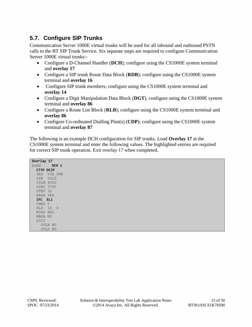
The following is an example DCH configuration for SIP trunks. Load Overlay 17 at the
CS1000E system terminal and enter the following values. The highlighted entries are required
for correct SIP trunk operation. Exit overlay 17 when completed.
Overlay 17 ADAN DCH 1 CTYP DCIP DES VIR_TRK
USR ISLD
ISLM 4000
SSRC 3700
OTBF 32
NASA YES
IFC SL1 CNEG 1
RLS ID 4
RCAP ND2
MBGA NO
H323
OVLR NO
OVLS NO
CMN; Reviewed:
SPOC 07/23/2014
Solution & Interoperability Test Lab Application Notes
©2014 Avaya Inc. All Rights Reserved.
16 of 50
BTNOASCS1K76SM
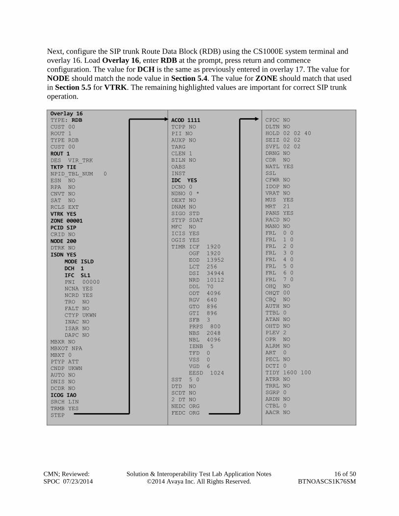
Next, configure the SIP trunk Route Data Block (RDB) using the CS1000E system terminal and
overlay 16. Load Overlay 16, enter RDB at the prompt, press return and commence
configuration. The value for DCH is the same as previously entered in overlay 17. The value for
NODE should match the node value in Section 5.4. The value for ZONE should match that used
in Section 5.5 for VTRK. The remaining highlighted values are important for correct SIP trunk
operation.
Overlay 16 TYPE: RDB
CUST 00
ROUT 1
TYPE RDB
CUST 00
ROUT 1 DES VIR_TRK
TKTP TIE NPID_TBL_NUM 0
ESN NO
RPA NO
CNVT NO
SAT NO
RCLS EXT
VTRK YES ZONE 00001 PCID SIP CRID NO
NODE 200 DTRK NO
ISDN YES MODE ISLD DCH 1 IFC SL1 PNI 00000
NCNA YES
NCRD YES
TRO NO
FALT NO
CTYP UKWN
INAC NO
ISAR NO
DAPC NO
MBXR NO
MBXOT NPA
MBXT 0
PTYP ATT
CNDP UKWN
AUTO NO
DNIS NO
DCDR NO
ICOG IAO SRCH LIN
TRMB YES
STEP
ACOD 1111 TCPP NO
PII NO
AUXP NO
TARG
CLEN 1
BILN NO
OABS
INST
IDC YES DCNO 0
NDNO 0 *
DEXT NO
DNAM NO
SIGO STD
STYP SDAT
MFC NO
ICIS YES
OGIS YES
TIMR ICF 1920
OGF 1920
EOD 13952
LCT 256
DSI 34944
NRD 10112
DDL 70
ODT 4096
RGV 640
GTO 896
GTI 896
SFB 3
PRPS 800
NBS 2048
NBL 4096
IENB 5
TFD 0
VSS 0
VGD 6
EESD 1024
SST 5 0
DTD NO
SCDT NO
2 DT NO
NEDC ORG
FEDC ORG
CPDC NO
DLTN NO
HOLD 02 02 40
SEIZ 02 02
SVFL 02 02
DRNG NO
CDR NO
NATL YES
SSL
CFWR NO
IDOP NO
VRAT NO
MUS YES
MRT 21
PANS YES
RACD NO
MANO NO
FRL 0 0
FRL 1 0
FRL 2 0
FRL 3 0
FRL 4 0
FRL 5 0
FRL 6 0
FRL 7 0
OHQ NO
OHQT 00
CBQ NO
AUTH NO
TTBL 0
ATAN NO
OHTD NO
PLEV 2
OPR NO
ALRM NO
ART 0
PECL NO
DCTI 0
TIDY 1600 100
ATRR NO
TRRL NO
SGRP 0
ARDN NO
CTBL 0
AACR NO
CMN; Reviewed:
SPOC 07/23/2014
Solution & Interoperability Test Lab Application Notes
©2014 Avaya Inc. All Rights Reserved.
17 of 50
BTNOASCS1K76SM
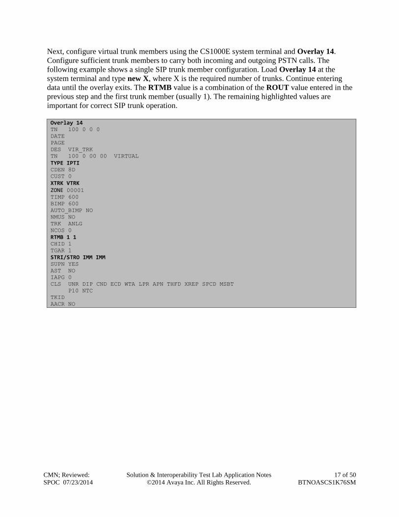
Next, configure virtual trunk members using the CS1000E system terminal and Overlay 14.
Configure sufficient trunk members to carry both incoming and outgoing PSTN calls. The
following example shows a single SIP trunk member configuration. Load Overlay 14 at the
system terminal and type new X, where X is the required number of trunks. Continue entering
data until the overlay exits. The RTMB value is a combination of the ROUT value entered in the
previous step and the first trunk member (usually 1). The remaining highlighted values are
important for correct SIP trunk operation.
Overlay 14 TN 100 0 0 0
DATE
PAGE
DES VIR_TRK
TN 100 0 00 00 VIRTUAL
TYPE IPTI CDEN 8D
CUST 0
XTRK VTRK ZONE 00001 TIMP 600
BIMP 600
AUTO_BIMP NO
NMUS NO
TRK ANLG
NCOS 0
RTMB 1 1 CHID 1
TGAR 1
STRI/STRO IMM IMM SUPN YES
AST NO
IAPG 0
CLS UNR DIP CND ECD WTA LPR APN THFD XREP SPCD MSBT
P10 NTC
TKID
AACR NO
CMN; Reviewed:
SPOC 07/23/2014
Solution & Interoperability Test Lab Application Notes
©2014 Avaya Inc. All Rights Reserved.
18 of 50
BTNOASCS1K76SM
Next, configure a Digit Manipulation data block (DGT) in overlay 86. Load Overlay 86 at the
system terminal and type new. The following example shows the values used. The value for
DMI is the same as when inputting the DMI value during configuration of the Route List Block.
Overlay 86 CUST 0
FEAT dgt
DMI 10 DEL 0
ISPN NO
CTYP NPA
Configure a Route List Block (RLB) in overlay 86. Load Overlay 86 at the system terminal and
type new. The following example shows the values used. The value for ROUT is the same as
previously entered in overlay 16. The RLI value is unique to each RLB.
Overlay 86 CUST 0
FEAT rlb
RLI 10 ELC NO
ENTR 0
LTER NO
ROUT 1 TOD 0 ON 1 ON 2 ON 3 ON
4 ON 5 ON 6 ON 7 ON
VNS NO
SCNV NO
CNV NO
EXP NO
FRL 0
DMI 10
CTBL 0
ISDM 0
FCI 0
FSNI 0
BNE NO
DORG NO
SBOC NRR
PROU 1
IDBB DBD
IOHQ NO
OHQ NO
CBQ NO
ISET 0
NALT 5
MFRL 0
OVLL 0
Next, configure Co-ordinated Dialling Plan(s) (CDP) which users will dial to reach PSTN
numbers. Use the CS1000E system terminal and Overlay 87. The following are some example
CDP entries used. The highlighted RLI value previously configured in overlay 86 is used as the
Route List Index (RLI), this is the default PSTN route to the SIP Trunk service.
TSC 00353
FLEN 0
RRPA NO
RLI 10 CCBA NO
TSC 18
FLEN 0
RRPA NO
RLI 10 CCBA NO
TSC 800
FLEN 0
RRPA NO
RLI 10 CCBA NO
TSC 08
FLEN 0
RRPA NO
RLI 10 CCBA NO
CMN; Reviewed:
SPOC 07/23/2014
Solution & Interoperability Test Lab Application Notes
©2014 Avaya Inc. All Rights Reserved.
19 of 50
BTNOASCS1K76SM
5.8. Configure Analog, Digital and IP Telephones
A variety of telephone types were used during the testing. The following is the configuration for
the Avaya 11xx and 12xx series Unistim IP telephones. Load Overlay 20 at the system terminal
and enter the following values. A unique four digit number is entered for the KEY 00. The value
for CFG_ZONE is the value used in Section 5.5 for IP telephones.
Load Overlay 20 IP Telephone configuration DES 1140
TN 100 0 03 0 VIRTUAL
TYPE 1140
CDEN 8D
CTYP XDLC
CUST 0
NUID
NHTN
CFG_ZONE 00002 CUR_ZONE 00002
ERL 0
ECL 0
FDN 0
TGAR 0
LDN NO
NCOS 0
SGRP 0
RNPG 1
SCI 0
SSU
LNRS 16
XLST
SCPW
SFLT NO
CAC_MFC 0
CLS UNR FBA WTA LPR PUA MTD FNA HTA TDD HFA CRPD
MWA LMPN RMMD SMWD AAD IMD XHD IRD NID OLD VCE DRG1
POD SLKD CCSD SWD LNA CNDA
CFTD SFD MRD DDV CNID CDCA MSID DAPA BFED RCBD
ICDA CDMD LLCN MCTD CLBD AUTR
GPUD DPUD DNDA CFXA ARHD FITD CLTD ASCD
CPFA CPTA ABDD CFHD FICD NAID BUZZ AGRD MOAD
UDI RCC HBTA AHD IPND DDGA NAMA MIND PRSD NRWD NRCD NROD
DRDD EXR0
USMD USRD ULAD CCBD RTDD RBDD RBHD PGND OCBD FLXD FTTC DNDY DNO3 MCBN
FDSD NOVD VOLA VOUD CDMR PRED RECA MCDD T87D SBMD KEM3 MSNV FRA PKCH MUTA MWTD
---continued on next page----
CMN; Reviewed:
SPOC 07/23/2014
Solution & Interoperability Test Lab Application Notes
©2014 Avaya Inc. All Rights Reserved.
20 of 50
BTNOASCS1K76SM
---continued from previous page----
DVLD CROD CROD
CPND_LANG ENG
RCO 0
HUNT 0
LHK 0
PLEV 02
PUID
DANI NO
AST 00
IAPG 1
AACS NO
ITNA NO
DGRP
MLWU_LANG 0
MLNG ENG
DNDR 0
KEY 00 MCR 6000 0 MARP CPND
CPND_LANG ROMAN
NAME IP1140
XPLN 10
DISPLAY_FMT FIRST,LAST
01 MCR 6000 0 CPND
CPND_LANG ROMAN
NAME IP1140
XPLN 10
DISPLAY_FMT FIRST,LAST
02
03 BSY
04 DSP
05
06
07
08
09
10
11
12
13
14
15
16
17 TRN
18 AO6
19 CFW 16
20 RGA
21 PRK
22 RNP
23
24 PRS
25 CHG
26 CPN
CMN; Reviewed:
SPOC 07/23/2014
Solution & Interoperability Test Lab Application Notes
©2014 Avaya Inc. All Rights Reserved.
21 of 50
BTNOASCS1K76SM
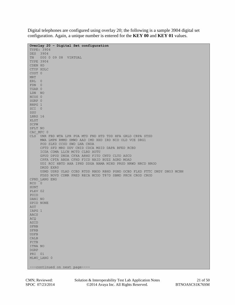
Digital telephones are configured using overlay 20; the following is a sample 3904 digital set
configuration. Again, a unique number is entered for the KEY 00 and KEY 01 values.
Overlay 20 – Digital Set configuration
TYPE: 3904
DES 3904
TN 000 0 09 08 VIRTUAL
TYPE 3904
CDEN 8D
CTYP XDLC
CUST 0
MRT
ERL 0
FDN 0
TGAR 0
LDN NO
NCOS 0
SGRP 0
RNPG 1
SCI 0
SSU
LNRS 16
XLST
SCPW
SFLT NO
CAC_MFC 0
CLS UNR FBD WTA LPR PUA MTD FND HTD TDD HFA GRLD CRPA STSD
MWA LMPN RMMD SMWD AAD IMD XHD IRD NID OLD VCE DRG1
POD SLKD CCSD SWD LNA CNDA
CFTD SFD MRD DDV CNID CDCA MSID DAPA BFED RCBD
ICDA CDMA LLCN MCTD CLBD AUTU
GPUD DPUD DNDA CFXA ARHD FITD CNTD CLTD ASCD
CPFA CPTA ABDA CFHD FICD NAID BUZZ AGRD MOAD
UDI RCC HBTD AHA IPND DDGA NAMA MIND PRSD NRWD NRCD NROD
DRDD EXR0
USMD USRD ULAD CCBD RTDD RBDD RBHD PGND OCBD FLXD FTTC DNDY DNO3 MCBN
FDSD NOVD CDMR PRED RECA MCDD T87D SBMD PKCH CROD CROD
CPND_LANG ENG
RCO 0
HUNT
PLEV 02
PUID
DANI NO
SPID NONE
AST
IAPG 1
AACS
ACQ
ASID
SFNB
SFRB
USFB
CALB
FCTB
ITNA NO
DGRP
PRI 01
MLWU_LANG 0
---continued on next page----
CMN; Reviewed:
SPOC 07/23/2014
Solution & Interoperability Test Lab Application Notes
©2014 Avaya Inc. All Rights Reserved.
22 of 50
BTNOASCS1K76SM
---continued from previous page----
MLNG ENG
DNDR 0
KEY 00 MCR 6066 0 MARP CPND
CPND_LANG ROMAN
NAME Digital Set
XPLN 10
DISPLAY_FMT FIRST,LAST
01 MCR 6066 0 CPND
CPND_LANG ROMAN
NAME Digital Set
XPLN 10
DISPLAY_FMT FIRST,LAST
02 DSP
03 MSB
04
05
06
07
08
09
10
11
12
13
14
15
16
17 TRN
18 AO6
19 CFW 16
20 RGA
21 PRK
22 RNP
23
24 PRS
25 CHG
26 CPN
27 CLT
28 RLT
29
30
31
CMN; Reviewed:
SPOC 07/23/2014
Solution & Interoperability Test Lab Application Notes
©2014 Avaya Inc. All Rights Reserved.
23 of 50
BTNOASCS1K76SM
Analog telephones are also configured using overlay 20; the following example shows an analog
port configured for Plain Ordinary Telephone Service (POTS) and to allow T.38 Fax
transmission. A unique value is entered for DN, this is the extension number. DTN is required if
the telephone uses DTMF dialing. Values FAXA and MPTD configure the port for T.38 Fax
transmissions.
Overlay 20 – Analog Telephone Configuration
DES 500
TN 100 0 00 03
TYPE 500
CDEN 4D
CUST 0
MRT
ERL 00000
WRLS NO
DN 52002
AST NO
IAPG 0
HUNT
TGAR 0
LDN NO
NCOS 0
SGRP 0
RNPG 0
XLST
SCI 0
SCPW
SFLT NO
CAC_MFC 0
CLS UNR DTN FBD XFD WTA THFD FND HTD ONS
LPR XRD AGRD CWD SWD MWD RMMD SMWD LPD XHD SLKD CCSD LND TVD
CFTD SFD MRD C6D CNID CLBD AUTU
ICDD CDMD LLCN EHTD MCTD
GPUD DPUD CFXD ARHD OVDD AGTD CLTD LDTD ASCD SDND
MBXD CPFA CPTA UDI RCC HBTD IRGD DDGA NAMA MIND
NRWD NRCD NROD SPKD CRD PRSD MCRD
EXR0 SHL SMSD ABDD CFHD DNDY DNO3
CWND USMD USRD CCBD BNRD OCBD RTDD RBDD RBHD FAXA CNUD CNAD PGND FTTC
FDSD NOVD CDMR PRED MCDD T87D SBMD PKCH MPTD
PLEV 02
PUID
AACS NO
MLWU_LANG 0
FTR DCFW 4
CMN; Reviewed:
SPOC 07/23/2014
Solution & Interoperability Test Lab Application Notes
©2014 Avaya Inc. All Rights Reserved.
24 of 50
BTNOASCS1K76SM
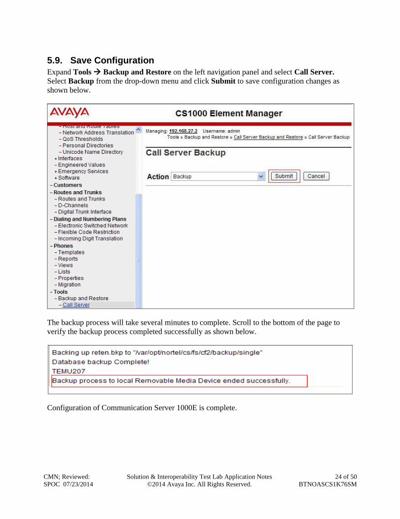
5.9. Save Configuration
Expand Tools Backup and Restore on the left navigation panel and select Call Server.
Select Backup from the drop-down menu and click Submit to save configuration changes as
shown below.
The backup process will take several minutes to complete. Scroll to the bottom of the page to
verify the backup process completed successfully as shown below.
Configuration of Communication Server 1000E is complete.
CMN; Reviewed:
SPOC 07/23/2014
Solution & Interoperability Test Lab Application Notes
©2014 Avaya Inc. All Rights Reserved.
25 of 50
BTNOASCS1K76SM
6. Configuring Avaya Aura® Session Manager This section provides the procedures for configuring Session Manager. Session Manager is
configured via System Manager. The procedures include the following areas:
Log in to Avaya Aura® System Manager.
Administer SIP domain.
Administer SIP Location.
Administer Adaptations.
Administer SIP Entities.
Administer Entity Links.
Administer Routing Policies.
Administer Dial Patterns.
It may not be necessary to create all the items above when creating a connection to the service
provider since some of these items would have already been defined as part of the initial Session
Manager installation. This includes items such as certain SIP domains, locations, SIP entities,
and Session Manager itself. However, each item should be reviewed to verify the configuration.
6.1. Log in to Avaya Aura® System Manager
Access the System Manager using a Web Browser by entering http://<FQDN >/SMGR, where
<FQDN> is the fully qualified domain name of System Manager. Log in using appropriate
credentials (not shown) and the Home tab will be presented with menu options shown below.
CMN; Reviewed:
SPOC 07/23/2014
Solution & Interoperability Test Lab Application Notes
©2014 Avaya Inc. All Rights Reserved.
26 of 50
BTNOASCS1K76SM
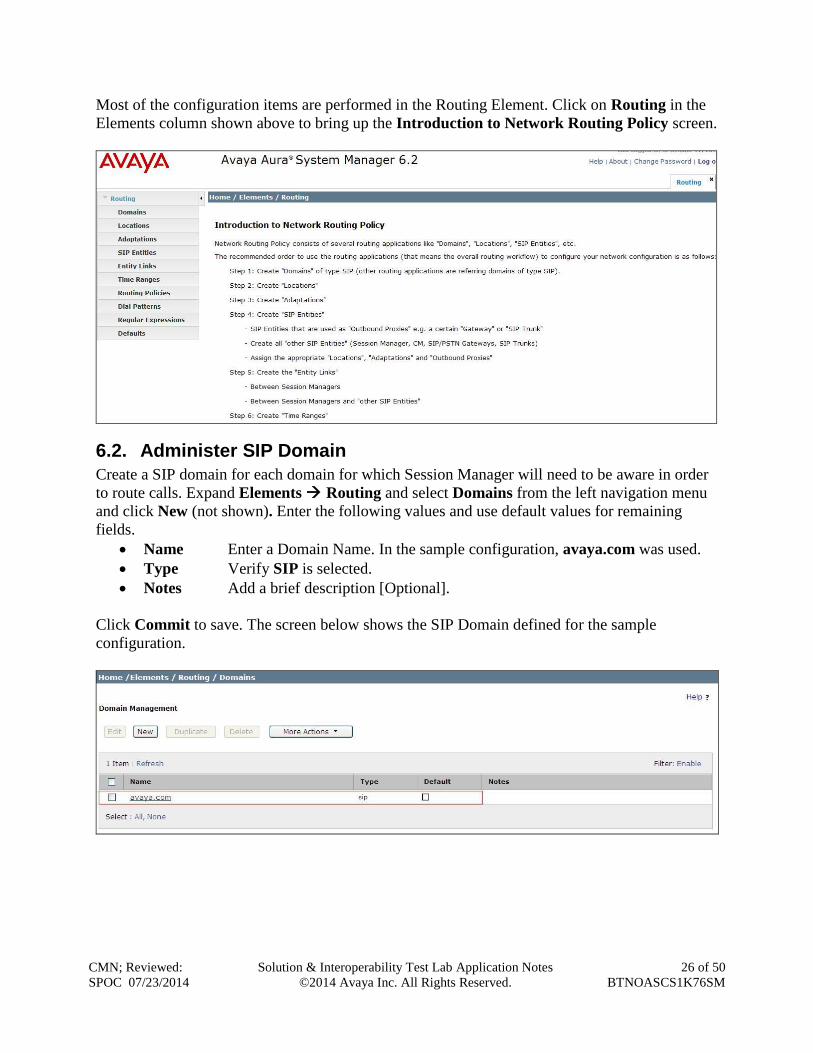
Most of the configuration items are performed in the Routing Element. Click on Routing in the
Elements column shown above to bring up the Introduction to Network Routing Policy screen.
6.2. Administer SIP Domain
Create a SIP domain for each domain for which Session Manager will need to be aware in order
to route calls. Expand Elements Routing and select Domains from the left navigation menu
and click New (not shown). Enter the following values and use default values for remaining
fields.
Name Enter a Domain Name. In the sample configuration, avaya.com was used.
Type Verify SIP is selected.
Notes Add a brief description [Optional].
Click Commit to save. The screen below shows the SIP Domain defined for the sample
configuration.
CMN; Reviewed:
SPOC 07/23/2014
Solution & Interoperability Test Lab Application Notes
©2014 Avaya Inc. All Rights Reserved.
27 of 50
BTNOASCS1K76SM
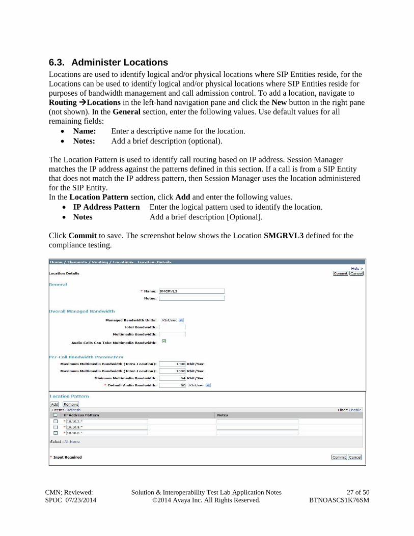
6.3. Administer Locations
Locations are used to identify logical and/or physical locations where SIP Entities reside, for the
Locations can be used to identify logical and/or physical locations where SIP Entities reside for
purposes of bandwidth management and call admission control. To add a location, navigate to
Routing Locations in the left-hand navigation pane and click the New button in the right pane
(not shown). In the General section, enter the following values. Use default values for all
remaining fields:
Name: Enter a descriptive name for the location.
Notes: Add a brief description (optional).
The Location Pattern is used to identify call routing based on IP address. Session Manager
matches the IP address against the patterns defined in this section. If a call is from a SIP Entity
that does not match the IP address pattern, then Session Manager uses the location administered
for the SIP Entity.
In the Location Pattern section, click Add and enter the following values.
IP Address Pattern Enter the logical pattern used to identify the location.
Notes Add a brief description [Optional].
Click Commit to save. The screenshot below shows the Location SMGRVL3 defined for the
compliance testing.
CMN; Reviewed:
SPOC 07/23/2014
Solution & Interoperability Test Lab Application Notes
©2014 Avaya Inc. All Rights Reserved.
28 of 50
BTNOASCS1K76SM
6.4. Administer Adaptations
Adaptations can be used to modify the called and calling party numbers to meet the requirements
of the service. The called party number present in the SIP INVITE Request URI is modified by
the Digit Conversion in the Adaptation. The example below was applied to the BT NOAS SBC
SIP Entities and was used in test to convert numbers being passed between BT NOAS SBC’s and
Session Manager.
To add an adaptation, under the Routing tab select Adaptations on the left hand menu and then
click on the New button (not shown). Under Adaption Details General:
In the Adaptation name field enter an informative name.
In the Module name field click on the down arrow and then select the <click to add
module> entry from the drop down list and type DigitConversionAdapter in the
resulting New Module Name field.
Module parameter MIME =no Strips MIME message bodies on egress from
Session Manager
fromto=true Modifies SIP From and To headers of a message
Scroll down the page and under Digit Conversion for Incoming Calls to SM, click the Add
button and specify the digit manipulation to be performed as follows:
Enter the leading digits that will be matched in the Matching Pattern field.
In the Min and Max fields, set the minimum and maximum digits allowed in the digit
string to be matched.
In the Delete Digits field, enter the number of leading digits to be removed.
In the Insert Digits field, specify the digits to be prefixed to the digit string.
In the Address to modify field, specify the digits to be manipulated by the adaptation. In
this configuration the dialed number is the target so both has been selected.
CMN; Reviewed:
SPOC 07/23/2014
Solution & Interoperability Test Lab Application Notes
©2014 Avaya Inc. All Rights Reserved.
29 of 50
BTNOASCS1K76SM
This will ensure any incoming numbers will have the + symbol and international dialing code
removed before being presented to the Communication Server 1000E.
In the Digit Conversion for Outgoing Calls to SM section, click Add and enter the following
values.
Matching Pattern Enter dialed prefix for calls to SIP endpoints registered to Session
Manager
Min Enter minimum number of digits that must be dialed
Max Enter maximum number of digits that may be dialed
Delete Digits Enter number of digits that may be deleted
Insert Digits Enter number of digits to be added before the dialed number
Address to Modify Select both
This will ensure any destination numbers beginning with 6 with have a specified CLID presented
on outbound calls.
CMN; Reviewed:
SPOC 07/23/2014
Solution & Interoperability Test Lab Application Notes
©2014 Avaya Inc. All Rights Reserved.
30 of 50
BTNOASCS1K76SM
6.5. Administer SIP Entities
A SIP Entity must be added for each SIP-based telephony system supported by a SIP connection
to the Session Manager. To add a SIP Entity, select SIP Entities on the left panel menu and then
click on the New button (not shown). The following will need to be entered for each SIP Entity.
Under General:
In the Name field, enter an informative name
In the FQDN or IP Address field, enter the IP address of Session Manager or the
signalling interface on the connecting system
In the Type field, use Session Manager for a Session Manager SIP entity, Other for a
Communication Server 1000E SIP entity, and SIP Trunk for the Session Border
Controller SIP entity
In the Adaptation field (not available for the Session Manager SIP Entity), select the
appropriate Adaptation from the drop down menu
In the Location field, select the appropriate location from the drop down menu
In the Time Zone field, enter the time zone for the SIP Entity
In this configuration there are three SIP Entities:
Avaya Aura® Session Manager SIP Entity
Avaya Communication Server 1000E SIP Entity
BT NOAS SBC SIP Entities
6.5.1. Avaya Aura® Session Manager SIP Entity
The following screens show the SIP entity for Session Manager. The FQDN or IP Address field
is set to the IP address of the Session Manager SIP signaling interface.
CMN; Reviewed:
SPOC 07/23/2014
Solution & Interoperability Test Lab Application Notes
©2014 Avaya Inc. All Rights Reserved.
31 of 50
BTNOASCS1K76SM
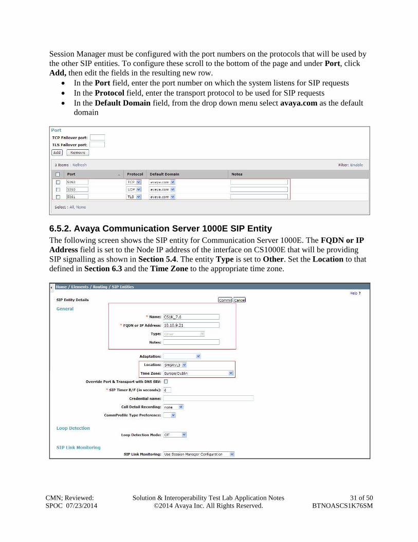
Session Manager must be configured with the port numbers on the protocols that will be used by
the other SIP entities. To configure these scroll to the bottom of the page and under Port, click
Add, then edit the fields in the resulting new row.
In the Port field, enter the port number on which the system listens for SIP requests
In the Protocol field, enter the transport protocol to be used for SIP requests
In the Default Domain field, from the drop down menu select avaya.com as the default
domain
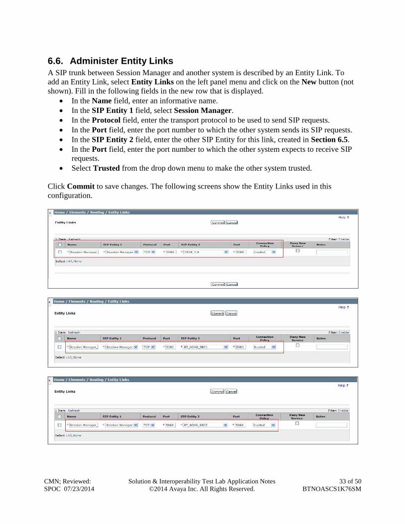
6.5.2. Avaya Communication Server 1000E SIP Entity
The following screen shows the SIP entity for Communication Server 1000E. The FQDN or IP
Address field is set to the Node IP address of the interface on CS1000E that will be providing
SIP signalling as shown in Section 5.4. The entity Type is set to Other. Set the Location to that
defined in Section 6.3 and the Time Zone to the appropriate time zone.
CMN; Reviewed:
SPOC 07/23/2014
Solution & Interoperability Test Lab Application Notes
©2014 Avaya Inc. All Rights Reserved.
32 of 50
BTNOASCS1K76SM
6.5.3. BT NOAS SBC SIP Entities
The following screenshots display the SIP entities for BT NOAS used for routing calls. Two SIP
Entities were used for the two interfaces established so that routing could take place to both BT
NOAS SBCs. The FQDN or IP Address field is set to the IP addresses of the BT NOAS SBC’s.
Set Type to SIP Trunk. Set Adaptation to the one created in Section 6.4. Set the location to
that defined in Section 6.3 and the Time Zone to the appropriate time zone.
CMN; Reviewed:
SPOC 07/23/2014
Solution & Interoperability Test Lab Application Notes
©2014 Avaya Inc. All Rights Reserved.
33 of 50
BTNOASCS1K76SM
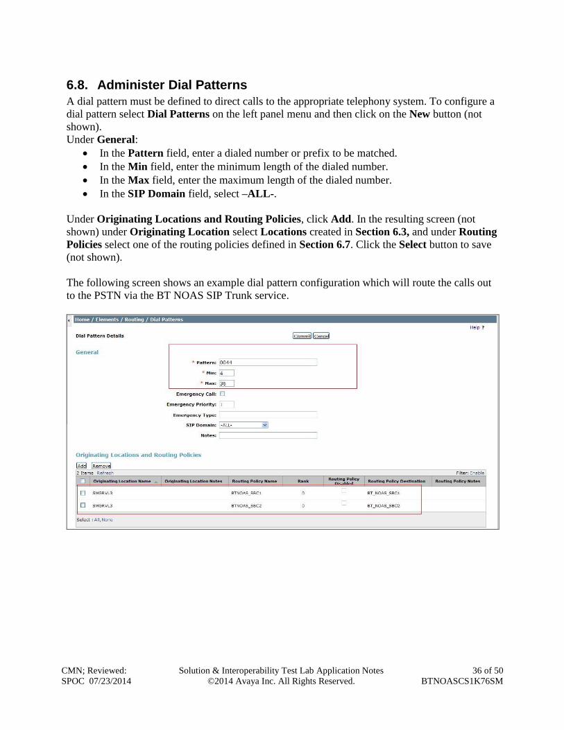
6.6. Administer Entity Links
A SIP trunk between Session Manager and another system is described by an Entity Link. To
add an Entity Link, select Entity Links on the left panel menu and click on the New button (not
shown). Fill in the following fields in the new row that is displayed.
In the Name field, enter an informative name.
In the SIP Entity 1 field, select Session Manager.
In the Protocol field, enter the transport protocol to be used to send SIP requests.
In the Port field, enter the port number to which the other system sends its SIP requests.
In the SIP Entity 2 field, enter the other SIP Entity for this link, created in Section 6.5.
In the Port field, enter the port number to which the other system expects to receive SIP
requests.
Select Trusted from the drop down menu to make the other system trusted.
Click Commit to save changes. The following screens show the Entity Links used in this
configuration.
CMN; Reviewed:
SPOC 07/23/2014
Solution & Interoperability Test Lab Application Notes
©2014 Avaya Inc. All Rights Reserved.
34 of 50
BTNOASCS1K76SM
6.7. Administer Routing Policies
Routing policies must be created to direct how calls will be routed to a system. To add a routing
policy, select Routing Policies on the left panel menu and then click on the New button (not
shown).
Under General:
Enter an informative name in the Name field.
Under SIP Entity as Destination, click Select, and then select the appropriate SIP entity
to which this routing policy applies.
The following screen shows the routing policy for Communication Server 1000E:
The following screenshots display the routing policies for the BT NOAS SBC’s:
CMN; Reviewed:
SPOC 07/23/2014
Solution & Interoperability Test Lab Application Notes
©2014 Avaya Inc. All Rights Reserved.
35 of 50
BTNOASCS1K76SM
CMN; Reviewed:
SPOC 07/23/2014
Solution & Interoperability Test Lab Application Notes
©2014 Avaya Inc. All Rights Reserved.
36 of 50
BTNOASCS1K76SM
6.8. Administer Dial Patterns
A dial pattern must be defined to direct calls to the appropriate telephony system. To configure a
dial pattern select Dial Patterns on the left panel menu and then click on the New button (not
shown).
Under General:
In the Pattern field, enter a dialed number or prefix to be matched.
In the Min field, enter the minimum length of the dialed number.
In the Max field, enter the maximum length of the dialed number.
In the SIP Domain field, select –ALL-.
Under Originating Locations and Routing Policies, click Add. In the resulting screen (not
shown) under Originating Location select Locations created in Section 6.3, and under Routing
Policies select one of the routing policies defined in Section 6.7. Click the Select button to save
(not shown).
The following screen shows an example dial pattern configuration which will route the calls out
to the PSTN via the BT NOAS SIP Trunk service.
CMN; Reviewed:
SPOC 07/23/2014
Solution & Interoperability Test Lab Application Notes
©2014 Avaya Inc. All Rights Reserved.
37 of 50
BTNOASCS1K76SM
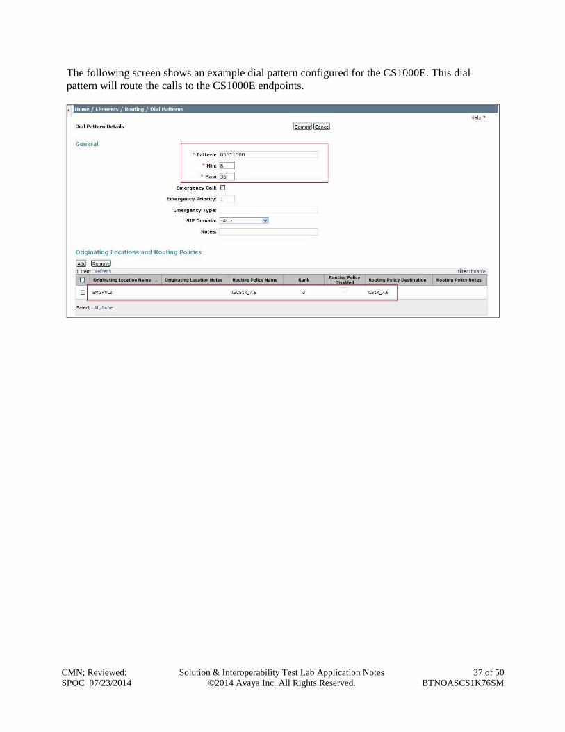
The following screen shows an example dial pattern configured for the CS1000E. This dial
pattern will route the calls to the CS1000E endpoints.
CMN; Reviewed:
SPOC 07/23/2014
Solution & Interoperability Test Lab Application Notes
©2014 Avaya Inc. All Rights Reserved.
38 of 50
BTNOASCS1K76SM
7. BT NOAS Configuration The configuration of the BT NOAS equipment used to support the BT NOAS SIP Trunk service
is outside of the scope of these Application Notes and will not be covered. To obtain further
information on BT equipment and system configuration please contact an authorized BT
representative.
8. Verification Steps This section provides verification steps that may be performed in the field to verify that the
solution is configured properly.
8.1. Avaya Communication Server 1000E Verification
This section illustrates sample verifications that may be performed using the Avaya CS1000E
Element Manager GUI.
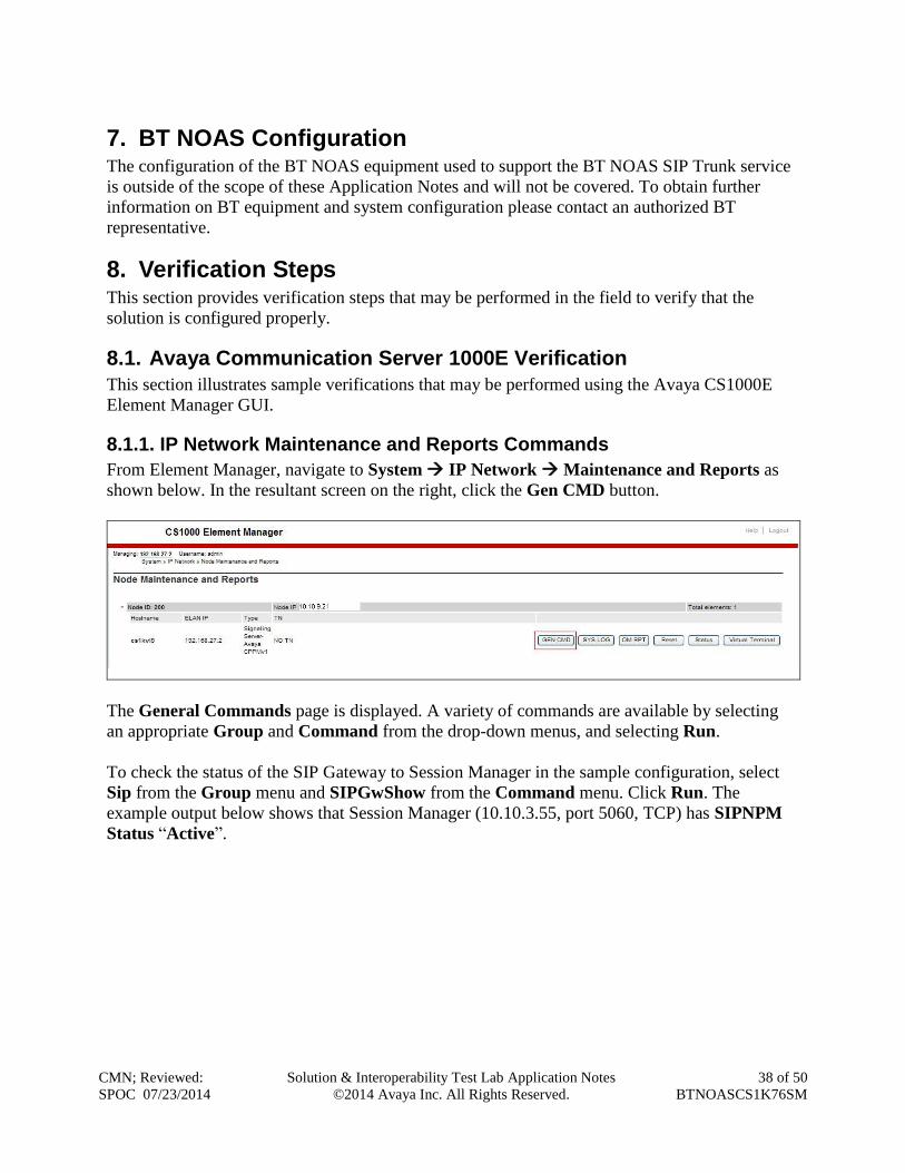
8.1.1. IP Network Maintenance and Reports Commands
From Element Manager, navigate to System IP Network Maintenance and Reports as
shown below. In the resultant screen on the right, click the Gen CMD button.
The General Commands page is displayed. A variety of commands are available by selecting
an appropriate Group and Command from the drop-down menus, and selecting Run.
To check the status of the SIP Gateway to Session Manager in the sample configuration, select
Sip from the Group menu and SIPGwShow from the Command menu. Click Run. The
example output below shows that Session Manager (10.10.3.55, port 5060, TCP) has SIPNPM
Status “Active”.
CMN; Reviewed:
SPOC 07/23/2014
Solution & Interoperability Test Lab Application Notes
©2014 Avaya Inc. All Rights Reserved.
39 of 50
BTNOASCS1K76SM
The following screen shows a means to view IP UniStim telephones. The screen shows the
output of the Command isetShow in Group Iset.
CMN; Reviewed:
SPOC 07/23/2014
Solution & Interoperability Test Lab Application Notes
©2014 Avaya Inc. All Rights Reserved.
40 of 50
BTNOASCS1K76SM
8.2. Verify Avaya Communication Server 1000E Operational Status
Expand System on the left navigation panel and select Maintenance. Select LD 96 - D-Channel
from the Select by Overlay table and the D-Channel Diagnostics function from the Select by
Functionality table as shown below.
Select the Status for D-Channel (STAT DCH) command and click Submit to verify status of
the virtual D-Channel as shown below. Verify the status of the following fields.
APPL_STATUS Verify status is OPER
LINK_STATUS Verify status is EST ACTV
CMN; Reviewed:
SPOC 07/23/2014
Solution & Interoperability Test Lab Application Notes
©2014 Avaya Inc. All Rights Reserved.
41 of 50
BTNOASCS1K76SM
8.3. Verify Avaya Aura® Session Manager Operational Status
8.3.1. Verify Avaya Aura® Session Manager is Operational
Navigate to Elements Session Manager Dashboard (not shown) to verify the overall
system status for Session Manager. Specifically, verify the status of the following fields as
shown below.
Navigate to Elements Session Manager System Status Security Module Status (not
shown) to view more detailed information on the status of the Security Module for the specific
Session Manager. Verify the Status column displays Up as shown below.
CMN; Reviewed:
SPOC 07/23/2014
Solution & Interoperability Test Lab Application Notes
©2014 Avaya Inc. All Rights Reserved.
42 of 50
BTNOASCS1K76SM
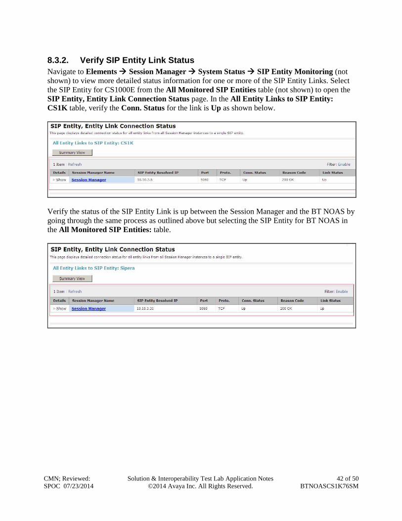
8.3.2. Verify SIP Entity Link Status
Navigate to Elements Session Manager System Status SIP Entity Monitoring (not
shown) to view more detailed status information for one or more of the SIP Entity Links. Select
the SIP Entity for CS1000E from the All Monitored SIP Entities table (not shown) to open the
SIP Entity, Entity Link Connection Status page. In the All Entity Links to SIP Entity:
CS1K table, verify the Conn. Status for the link is Up as shown below.
Verify the status of the SIP Entity Link is up between the Session Manager and the BT NOAS by
going through the same process as outlined above but selecting the SIP Entity for BT NOAS in
the All Monitored SIP Entities: table.
CMN; Reviewed:
SPOC 07/23/2014
Solution & Interoperability Test Lab Application Notes
©2014 Avaya Inc. All Rights Reserved.
43 of 50
BTNOASCS1K76SM
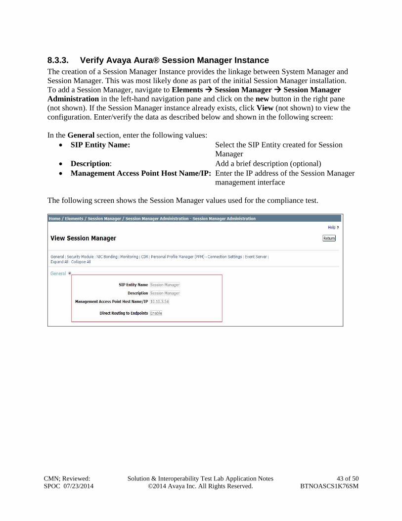
8.3.3. Verify Avaya Aura® Session Manager Instance
The creation of a Session Manager Instance provides the linkage between System Manager and
Session Manager. This was most likely done as part of the initial Session Manager installation.
To add a Session Manager, navigate to Elements Session Manager Session Manager
Administration in the left-hand navigation pane and click on the new button in the right pane
(not shown). If the Session Manager instance already exists, click View (not shown) to view the
configuration. Enter/verify the data as described below and shown in the following screen:
In the General section, enter the following values:
SIP Entity Name: Select the SIP Entity created for Session
Manager
Description: Add a brief description (optional)
Management Access Point Host Name/IP: Enter the IP address of the Session Manager
management interface
The following screen shows the Session Manager values used for the compliance test.
CMN; Reviewed:
SPOC 07/23/2014
Solution & Interoperability Test Lab Application Notes
©2014 Avaya Inc. All Rights Reserved.
44 of 50
BTNOASCS1K76SM
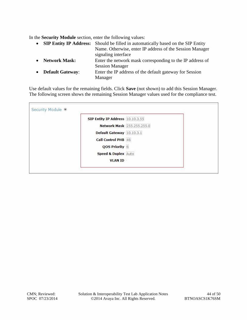
In the Security Module section, enter the following values:
SIP Entity IP Address: Should be filled in automatically based on the SIP Entity
Name. Otherwise, enter IP address of the Session Manager
signaling interface
Network Mask: Enter the network mask corresponding to the IP address of
Session Manager
Default Gateway: Enter the IP address of the default gateway for Session
Manager
Use default values for the remaining fields. Click Save (not shown) to add this Session Manager.
The following screen shows the remaining Session Manager values used for the compliance test.
CMN; Reviewed:
SPOC 07/23/2014
Solution & Interoperability Test Lab Application Notes
©2014 Avaya Inc. All Rights Reserved.
45 of 50
BTNOASCS1K76SM
9. Conclusion These Application Notes describe the configuration necessary to connect Avaya Aura®
Communication Server 1000E R7.6 and Avaya Aura® Session Manager R6.3 to BT NOAS SIP
Trunk service. BT NOAS SIP Trunk service is a SIP-based Voice over IP solution providing
businesses a flexible, cost-saving alternative to traditional hardwired telephony trunks. The
service was successfully tested with a number of observations listed in Section 2.2.
10. References This section references the documentation relevant to these Application Notes. Additional Avaya
product documentation is available at http://support.avaya.com.
[1] Implementing Avaya Aura® Session Manager, Release 6.3
[2] Installing Service Packs for Avaya Aura® Session Manager, Release 6.3
[3] Upgrading Avaya Aura® Session Manager, Release 6.3
[4] Maintaining and Troubleshooting Avaya Aura® Session Manager Release 6.3
[5] Installing and Configuring Avaya Aura® System Platform Release 6.3, June 2013
[6] Implementing Avaya Aura® System Manager Release 6.3, June 2013
[7] Upgrading Avaya Aura® System Manager to 6.3.2, July 2013
[8] Avaya Communication Server 1000E Installation and Commissioning, April 2012,
Document Number NN43041-310.
[9] Feature Listing Reference Avaya Communication Server 1000, November 2010,
Document Number NN43001-111, 05.01.
[10] Linux Platform Base and Applications Installation and Commissioning Avaya
Communication Server 1000, April 2013, Document Number NN43001-315
[11] Unified Communications Management Common Servers Fundamentals Avaya
Communication Server 1000, February 2013, Document Number NN43001-116
[12] Software Input Output Reference – Maintenance Avaya Communication Server 1000,
April 2012, Document Number NN43001-711
[13] Signaling Server IP Line Applications Fundamentals Avaya Communication Server 1000,
October 2011, Document Number NN43001-125
[14] SIP Software for Avaya 1100 Series IP Deskphones-Administration, December 2011,
Document Number NN43170-600
[15] RFC 3261 SIP: Session Initiation Protocol, http://www.ietf.org/
CMN; Reviewed:
SPOC 07/23/2014
Solution & Interoperability Test Lab Application Notes
©2014 Avaya Inc. All Rights Reserved.
46 of 50
BTNOASCS1K76SM
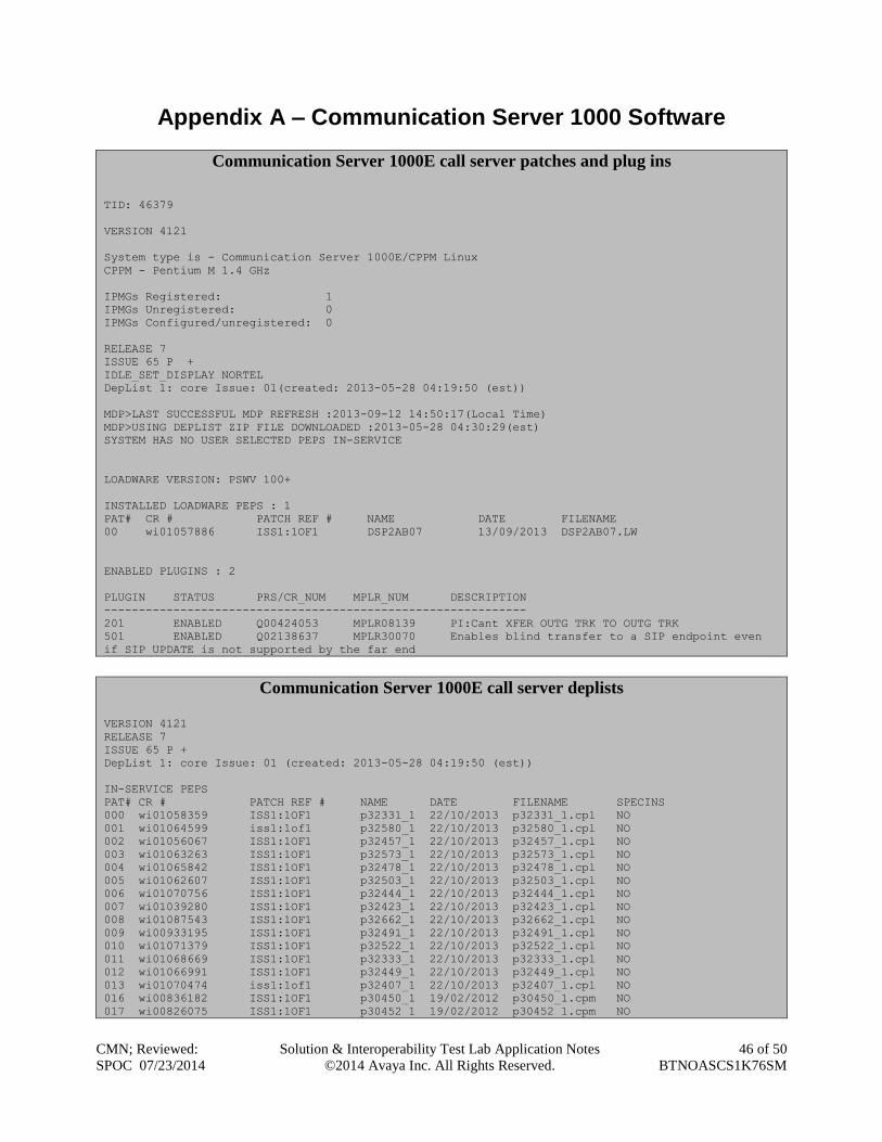
Appendix A – Communication Server 1000 Software
Communication Server 1000E call server patches and plug ins
TID: 46379
VERSION 4121
System type is - Communication Server 1000E/CPPM Linux
CPPM - Pentium M 1.4 GHz
IPMGs Registered: 1
IPMGs Unregistered: 0
IPMGs Configured/unregistered: 0
RELEASE 7
ISSUE 65 P +
IDLE_SET_DISPLAY NORTEL
DepList 1: core Issue: 01(created: 2013-05-28 04:19:50 (est))
MDP>LAST SUCCESSFUL MDP REFRESH :2013-09-12 14:50:17(Local Time)
MDP>USING DEPLIST ZIP FILE DOWNLOADED :2013-05-28 04:30:29(est)
SYSTEM HAS NO USER SELECTED PEPS IN-SERVICE
LOADWARE VERSION: PSWV 100+
INSTALLED LOADWARE PEPS : 1
PAT# CR # PATCH REF # NAME DATE FILENAME
00 wi01057886 ISS1:1OF1 DSP2AB07 13/09/2013 DSP2AB07.LW
ENABLED PLUGINS : 2
PLUGIN STATUS PRS/CR_NUM MPLR_NUM DESCRIPTION
-------------------------------------------------------------
201 ENABLED Q00424053 MPLR08139 PI:Cant XFER OUTG TRK TO OUTG TRK
501 ENABLED Q02138637 MPLR30070 Enables blind transfer to a SIP endpoint even
if SIP UPDATE is not supported by the far end
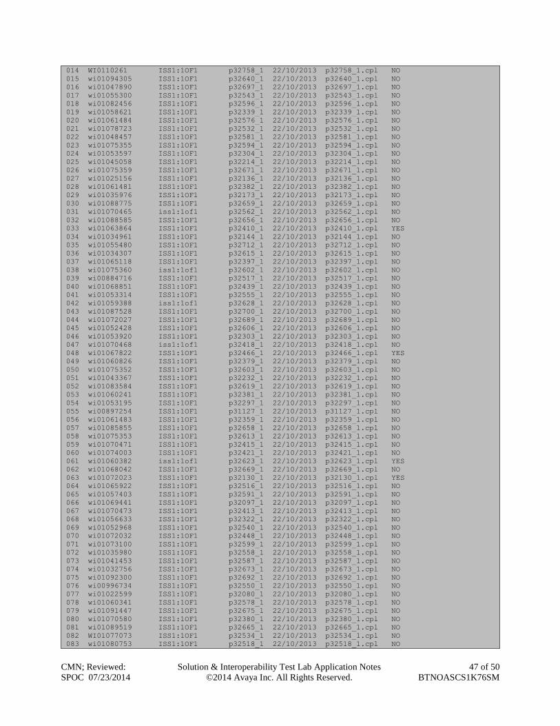
Communication Server 1000E call server deplists
VERSION 4121
RELEASE 7
ISSUE 65 P +
DepList 1: core Issue: 01 (created: 2013-05-28 04:19:50 (est))
IN-SERVICE PEPS
PAT# CR # PATCH REF # NAME DATE FILENAME SPECINS
000 wi01058359 ISS1:1OF1 p32331_1 22/10/2013 p32331_1.cpl NO
001 wi01064599 iss1:1of1 p32580_1 22/10/2013 p32580_1.cpl NO
002 wi01056067 ISS1:1OF1 p32457_1 22/10/2013 p32457_1.cpl NO
003 wi01063263 ISS1:1OF1 p32573_1 22/10/2013 p32573_1.cpl NO
004 wi01065842 ISS1:1OF1 p32478_1 22/10/2013 p32478_1.cpl NO
005 wi01062607 ISS1:1OF1 p32503_1 22/10/2013 p32503_1.cpl NO
006 wi01070756 ISS1:1OF1 p32444_1 22/10/2013 p32444_1.cpl NO
007 wi01039280 ISS1:1OF1 p32423_1 22/10/2013 p32423_1.cpl NO
008 wi01087543 ISS1:1OF1 p32662_1 22/10/2013 p32662_1.cpl NO
009 wi00933195 ISS1:1OF1 p32491_1 22/10/2013 p32491_1.cpl NO
010 wi01071379 ISS1:1OF1 p32522_1 22/10/2013 p32522_1.cpl NO
011 wi01068669 ISS1:1OF1 p32333_1 22/10/2013 p32333_1.cpl NO
012 wi01066991 ISS1:1OF1 p32449_1 22/10/2013 p32449_1.cpl NO
013 wi01070474 iss1:1of1 p32407_1 22/10/2013 p32407_1.cpl NO
016 wi00836182 ISS1:1OF1 p30450_1 19/02/2012 p30450_1.cpm NO
017 wi00826075 ISS1:1OF1 p30452_1 19/02/2012 p30452_1.cpm NO
CMN; Reviewed:
SPOC 07/23/2014
Solution & Interoperability Test Lab Application Notes
©2014 Avaya Inc. All Rights Reserved.
47 of 50
BTNOASCS1K76SM
014 WI0110261 ISS1:1OF1 p32758_1 22/10/2013 p32758_1.cpl NO
015 wi01094305 ISS1:1OF1 p32640_1 22/10/2013 p32640_1.cpl NO
016 wi01047890 ISS1:1OF1 p32697_1 22/10/2013 p32697_1.cpl NO
017 wi01055300 ISS1:1OF1 p32543_1 22/10/2013 p32543_1.cpl NO
018 wi01082456 ISS1:1OF1 p32596_1 22/10/2013 p32596_1.cpl NO
019 wi01058621 ISS1:1OF1 p32339_1 22/10/2013 p32339_1.cpl NO
020 wi01061484 ISS1:1OF1 p32576_1 22/10/2013 p32576_1.cpl NO
021 wi01078723 ISS1:1OF1 p32532_1 22/10/2013 p32532_1.cpl NO
022 wi01048457 ISS1:1OF1 p32581_1 22/10/2013 p32581_1.cpl NO
023 wi01075355 ISS1:1OF1 p32594_1 22/10/2013 p32594_1.cpl NO
024 wi01053597 ISS1:1OF1 p32304_1 22/10/2013 p32304_1.cpl NO
025 wi01045058 ISS1:1OF1 p32214_1 22/10/2013 p32214_1.cpl NO
026 wi01075359 ISS1:1OF1 p32671_1 22/10/2013 p32671_1.cpl NO
027 wi01025156 ISS1:1OF1 p32136_1 22/10/2013 p32136_1.cpl NO
028 wi01061481 ISS1:1OF1 p32382_1 22/10/2013 p32382_1.cpl NO
029 wi01035976 ISS1:1OF1 p32173_1 22/10/2013 p32173_1.cpl NO
030 wi01088775 ISS1:1OF1 p32659_1 22/10/2013 p32659_1.cpl NO
031 wi01070465 iss1:1of1 p32562_1 22/10/2013 p32562_1.cpl NO
032 wi01088585 ISS1:1OF1 p32656_1 22/10/2013 p32656_1.cpl NO
033 wi01063864 ISS1:1OF1 p32410_1 22/10/2013 p32410_1.cpl YES
034 wi01034961 ISS1:1OF1 p32144_1 22/10/2013 p32144_1.cpl NO
035 wi01055480 ISS1:1OF1 p32712_1 22/10/2013 p32712_1.cpl NO
036 wi01034307 ISS1:1OF1 p32615_1 22/10/2013 p32615_1.cpl NO
037 wi01065118 ISS1:1OF1 p32397_1 22/10/2013 p32397_1.cpl NO
038 wi01075360 iss1:1of1 p32602_1 22/10/2013 p32602_1.cpl NO
039 wi00884716 ISS1:1OF1 p32517_1 22/10/2013 p32517_1.cpl NO
040 wi01068851 ISS1:1OF1 p32439_1 22/10/2013 p32439_1.cpl NO
041 wi01053314 ISS1:1OF1 p32555_1 22/10/2013 p32555_1.cpl NO
042 wi01059388 iss1:1of1 p32628_1 22/10/2013 p32628_1.cpl NO
043 wi01087528 ISS1:1OF1 p32700_1 22/10/2013 p32700_1.cpl NO
044 wi01072027 ISS1:1OF1 p32689_1 22/10/2013 p32689_1.cpl NO
045 wi01052428 ISS1:1OF1 p32606_1 22/10/2013 p32606_1.cpl NO
046 wi01053920 ISS1:1OF1 p32303_1 22/10/2013 p32303_1.cpl NO
047 wi01070468 iss1:1of1 p32418_1 22/10/2013 p32418_1.cpl NO
048 wi01067822 ISS1:1OF1 p32466_1 22/10/2013 p32466_1.cpl YES
049 wi01060826 ISS1:1OF1 p32379_1 22/10/2013 p32379_1.cpl NO
050 wi01075352 ISS1:1OF1 p32603_1 22/10/2013 p32603_1.cpl NO
051 wi01043367 ISS1:1OF1 p32232_1 22/10/2013 p32232_1.cpl NO
052 wi01083584 ISS1:1OF1 p32619_1 22/10/2013 p32619_1.cpl NO
053 wi01060241 ISS1:1OF1 p32381_1 22/10/2013 p32381_1.cpl NO
054 wi01053195 ISS1:1OF1 p32297_1 22/10/2013 p32297_1.cpl NO
055 wi00897254 ISS1:1OF1 p31127_1 22/10/2013 p31127_1.cpl NO
056 wi01061483 ISS1:1OF1 p32359_1 22/10/2013 p32359_1.cpl NO
057 wi01085855 ISS1:1OF1 p32658_1 22/10/2013 p32658_1.cpl NO
058 wi01075353 ISS1:1OF1 p32613_1 22/10/2013 p32613_1.cpl NO
059 wi01070471 ISS1:1OF1 p32415_1 22/10/2013 p32415_1.cpl NO
060 wi01074003 ISS1:1OF1 p32421_1 22/10/2013 p32421_1.cpl NO
061 wi01060382 iss1:1of1 p32623_1 22/10/2013 p32623_1.cpl YES
062 wi01068042 ISS1:1OF1 p32669_1 22/10/2013 p32669_1.cpl NO
063 wi01072023 ISS1:1OF1 p32130_1 22/10/2013 p32130_1.cpl YES
064 wi01065922 ISS1:1OF1 p32516_1 22/10/2013 p32516_1.cpl NO
065 wi01057403 ISS1:1OF1 p32591_1 22/10/2013 p32591_1.cpl NO
066 wi01069441 ISS1:1OF1 p32097_1 22/10/2013 p32097_1.cpl NO
067 wi01070473 ISS1:1OF1 p32413_1 22/10/2013 p32413_1.cpl NO
068 wi01056633 ISS1:1OF1 p32322_1 22/10/2013 p32322_1.cpl NO
069 wi01052968 ISS1:1OF1 p32540_1 22/10/2013 p32540_1.cpl NO
070 wi01072032 ISS1:1OF1 p32448_1 22/10/2013 p32448_1.cpl NO
071 wi01073100 ISS1:1OF1 p32599_1 22/10/2013 p32599_1.cpl NO
072 wi01035980 ISS1:1OF1 p32558_1 22/10/2013 p32558_1.cpl NO
073 wi01041453 ISS1:1OF1 p32587_1 22/10/2013 p32587_1.cpl NO
074 wi01032756 ISS1:1OF1 p32673_1 22/10/2013 p32673_1.cpl NO
075 wi01092300 ISS1:1OF1 p32692_1 22/10/2013 p32692_1.cpl NO
076 wi00996734 ISS1:1OF1 p32550_1 22/10/2013 p32550_1.cpl NO
077 wi01022599 ISS1:1OF1 p32080_1 22/10/2013 p32080_1.cpl NO
078 wi01060341 ISS1:1OF1 p32578_1 22/10/2013 p32578_1.cpl NO
079 wi01091447 ISS1:1OF1 p32675_1 22/10/2013 p32675_1.cpl NO
080 wi01070580 ISS1:1OF1 p32380_1 22/10/2013 p32380_1.cpl NO
081 wi01089519 ISS1:1OF1 p32665_1 22/10/2013 p32665_1.cpl NO
082 WI01077073 ISS1:1OF1 p32534_1 22/10/2013 p32534_1.cpl NO
083 wi01080753 ISS1:1OF1 p32518_1 22/10/2013 p32518_1.cpl NO
CMN; Reviewed:
SPOC 07/23/2014
Solution & Interoperability Test Lab Application Notes
©2014 Avaya Inc. All Rights Reserved.
48 of 50
BTNOASCS1K76SM
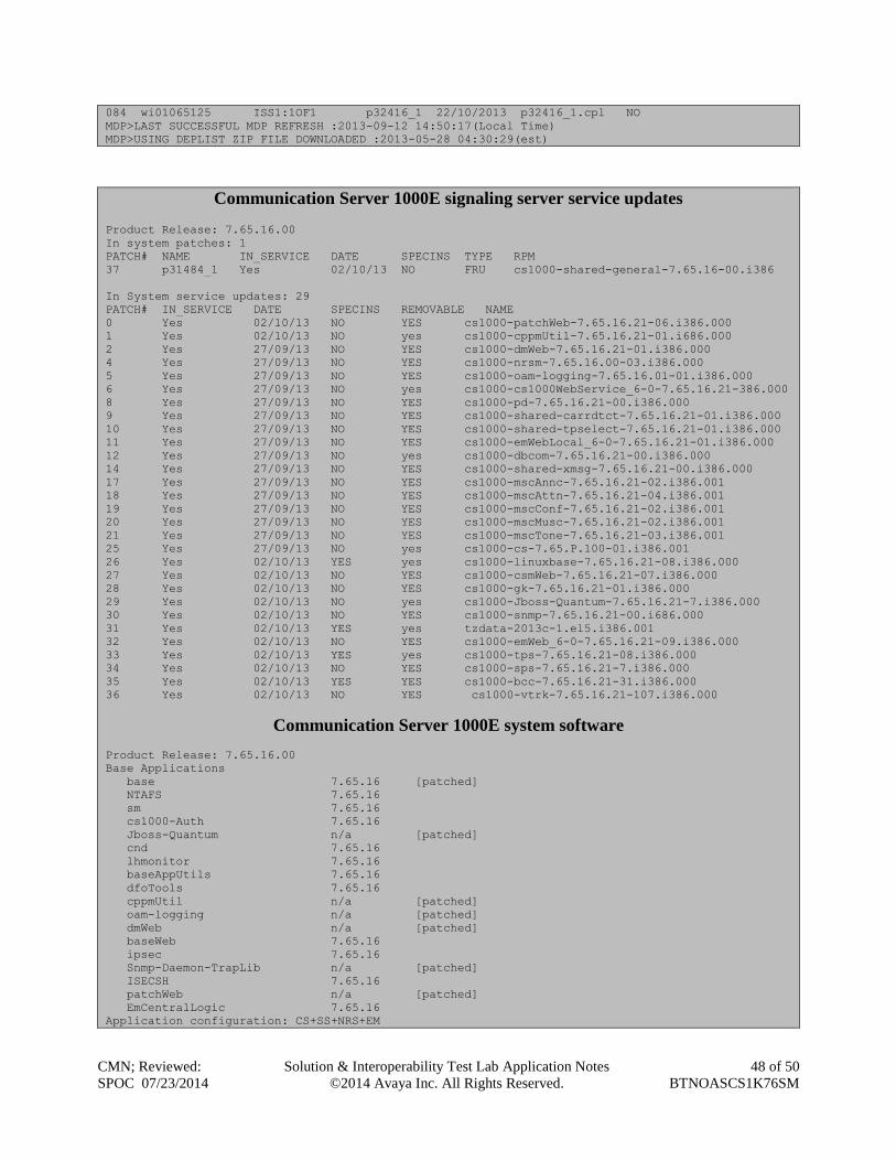
084 wi01065125 ISS1:1OF1 p32416_1 22/10/2013 p32416_1.cpl NO
MDP>LAST SUCCESSFUL MDP REFRESH :2013-09-12 14:50:17(Local Time)
MDP>USING DEPLIST ZIP FILE DOWNLOADED :2013-05-28 04:30:29(est)
Communication Server 1000E signaling server service updates
Product Release: 7.65.16.00
In system patches: 1
PATCH# NAME IN_SERVICE DATE SPECINS TYPE RPM
37 p31484_1 Yes 02/10/13 NO FRU cs1000-shared-general-7.65.16-00.i386
In System service updates: 29
PATCH# IN_SERVICE DATE SPECINS REMOVABLE NAME
0 Yes 02/10/13 NO YES cs1000-patchWeb-7.65.16.21-06.i386.000
1 Yes 02/10/13 NO yes cs1000-cppmUtil-7.65.16.21-01.i686.000
2 Yes 27/09/13 NO YES cs1000-dmWeb-7.65.16.21-01.i386.000
4 Yes 27/09/13 NO YES cs1000-nrsm-7.65.16.00-03.i386.000
5 Yes 27/09/13 NO YES cs1000-oam-logging-7.65.16.01-01.i386.000
6 Yes 27/09/13 NO yes cs1000-cs1000WebService_6-0-7.65.16.21-386.000
8 Yes 27/09/13 NO YES cs1000-pd-7.65.16.21-00.i386.000
9 Yes 27/09/13 NO YES cs1000-shared-carrdtct-7.65.16.21-01.i386.000
10 Yes 27/09/13 NO YES cs1000-shared-tpselect-7.65.16.21-01.i386.000
11 Yes 27/09/13 NO YES cs1000-emWebLocal_6-0-7.65.16.21-01.i386.000
12 Yes 27/09/13 NO yes cs1000-dbcom-7.65.16.21-00.i386.000
14 Yes 27/09/13 NO YES cs1000-shared-xmsg-7.65.16.21-00.i386.000
17 Yes 27/09/13 NO YES cs1000-mscAnnc-7.65.16.21-02.i386.001
18 Yes 27/09/13 NO YES cs1000-mscAttn-7.65.16.21-04.i386.001
19 Yes 27/09/13 NO YES cs1000-mscConf-7.65.16.21-02.i386.001
20 Yes 27/09/13 NO YES cs1000-mscMusc-7.65.16.21-02.i386.001
21 Yes 27/09/13 NO YES cs1000-mscTone-7.65.16.21-03.i386.001
25 Yes 27/09/13 NO yes cs1000-cs-7.65.P.100-01.i386.001
26 Yes 02/10/13 YES yes cs1000-linuxbase-7.65.16.21-08.i386.000
27 Yes 02/10/13 NO YES cs1000-csmWeb-7.65.16.21-07.i386.000
28 Yes 02/10/13 NO YES cs1000-gk-7.65.16.21-01.i386.000
29 Yes 02/10/13 NO yes cs1000-Jboss-Quantum-7.65.16.21-7.i386.000
30 Yes 02/10/13 NO YES cs1000-snmp-7.65.16.21-00.i686.000
31 Yes 02/10/13 YES yes tzdata-2013c-1.el5.i386.001
32 Yes 02/10/13 NO YES cs1000-emWeb_6-0-7.65.16.21-09.i386.000
33 Yes 02/10/13 YES yes cs1000-tps-7.65.16.21-08.i386.000
34 Yes 02/10/13 NO YES cs1000-sps-7.65.16.21-7.i386.000
35 Yes 02/10/13 YES YES cs1000-bcc-7.65.16.21-31.i386.000
36 Yes 02/10/13 NO YES cs1000-vtrk-7.65.16.21-107.i386.000
Communication Server 1000E system software
Product Release: 7.65.16.00
Base Applications
base 7.65.16 [patched]
NTAFS 7.65.16
sm 7.65.16
cs1000-Auth 7.65.16
Jboss-Quantum n/a [patched]
cnd 7.65.16
lhmonitor 7.65.16
baseAppUtils 7.65.16
dfoTools 7.65.16
cppmUtil n/a [patched]
oam-logging n/a [patched]
dmWeb n/a [patched]
baseWeb 7.65.16
ipsec 7.65.16
Snmp-Daemon-TrapLib n/a [patched]
ISECSH 7.65.16
patchWeb n/a [patched]
EmCentralLogic 7.65.16
Application configuration: CS+SS+NRS+EM
CMN; Reviewed:
SPOC 07/23/2014
Solution & Interoperability Test Lab Application Notes
©2014 Avaya Inc. All Rights Reserved.
49 of 50
BTNOASCS1K76SM
Packages:
CS+SS+NRS+EM
Configuration version: 7.65.16-00
cs 7.65.16 [patched]
dbcom 7.65.16.21 [patched]
cslogin 7.65.16
sigServerShare 7.65.16 [patched]
csv 7.65.16
tps 7.65.16.21 [patched]
vtrk 7.65.16.21 [patched]
pd 7.65.16.21 [patched]
sps 7.65.16.21 [patched]
ncs 7.65.16
gk 7.65.16.21 [patched]
nrsm 7.65.16 [patched]
nrsmWebService 7.65.16
managedElementWebService 7.65.16
EmConfig 7.65.16
emWeb_6-0 7.65.16 [patched]
emWebLocal_6-0 7.65.16 [patched]
csmWeb 7.65.16 [patched]
bcc 7.65.16 [patched]
ftrpkg 7.65.16
cs1000WebService_6-0 7.65.16 [patched]
mscAnnc 7.65.16.21 [patched]
mscAttn 7.65.16.21 [patched]
mscConf 7.65.16.21 [patched]
mscMusc 7.65.16.21 [patched]
mscTone 7.65.16.21 [patche
CMN; Reviewed:
SPOC 07/23/2014
Solution & Interoperability Test Lab Application Notes
©2014 Avaya Inc. All Rights Reserved.
50 of 50
BTNOASCS1K76SM
©2014 Avaya Inc. All Rights Reserved.
Avaya and the Avaya Logo are trademarks of Avaya Inc. All trademarks identified by ® and ™
are registered trademarks or trademarks, respectively, of Avaya Inc. All other trademarks are the
property of their respective owners. The information provided in these Application Notes is
subject to change without notice. The configurations, technical data, and recommendations
provided in these Application Notes are believed to be accurate and dependable, but are presented
without express or implied warranty. Users are responsible for their application of any products
specified in these Application Notes.
Please e-mail any questions or comments pertaining to these Application Notes along with the full
title name and filename, located in the lower right corner, directly to the Avaya DevConnect
Program at [email protected].