Application Notes for Configuring Avaya one-X™ Mobile and Avaya Communication Manager with AT&T Mobile Extension and ISDN-PRI Trunks – Issue 1.0
Abstract
These Application Notes describe the steps for configuring Avaya one-X™ Mobile and Avaya Communication Manager with AT&T Mobile Extension and ISDN-PRI trunks. Avaya one-X™ Mobile is an enterprise mobility solution that allows users roaming or otherwise located away from the office to access enterprise telephony and unified communications services. More specifically, users can utilize the Avaya one-X™ Mobile Unified Communication (UC) client application running on their mobile phones to manage the routing of inbound business calls, place outbound business calls, manage corporate voice messages, and search the corporate directory. The AT&T Mobile Extension offer is an integrated solution that provides all the necessary components to enable wireless-PBX integration at the enterprise, including a cost control capability for enterprise wireless usage. The AT&T Mobile Extension offer is based on the combination of enterprise communications products, AT&T wireless handsets, and AT&T wireless enterprise rate plans. AT&T is a member of the Avaya DevConnect Service Provider program. Information in these Application Notes has been obtained through compliance testing and additional technical discussions. Testing was conducted via the DevConnect Program at the Avaya Solution and Interoperability Test Lab.
2. Equipment and Software Validated ...................................................................................... 14 3. Avaya Communication Manager .......................................................................................... 15
3.1. System Parameters ........................................................................................................ 15 3.2. Dial Plan and Feature Access Codes ............................................................................ 19 3.3. Class of Restriction and Class of Service ..................................................................... 21 3.4. ISDN-PRI Trunk........................................................................................................... 23 3.5. PSTN Call Routing ....................................................................................................... 24
1. Introduction These Application Notes describe the steps for configuring Avaya one-X™ Mobile and Avaya Communication Manager with AT&T Mobile Extension and ISDN-PRI trunks. Avaya one-X™ Mobile is an enterprise mobility solution that allows users roaming or otherwise located away from the office to access enterprise telephony and unified communications services. More specifically, users can:
• Manage the routing of inbound business calls1 – Using the Avaya one-X™ Mobile UC client application (running on the mobile phone), users can select the destinations, e.g., office phone, mobile phone, home phone, other landline phones, etc., to which inbound business calls are routed. The users can then answer inbound business calls at any of the selected destinations.
• Place outbound business calls – Using the Avaya one-X™ Mobile UC client application, users can place outbound business calls from any phone, e.g., mobile phone, home phone, other landline phones, etc. Since these business calls are placed through the Avaya Communication Manager, the user’s business number is presented as the calling party number.
• Switch between using the office phone and mobile phone on active calls – Users can move active calls from the office phone to the mobile phone, and vice versa.
Note: SIP phones are not supported in the Avaya one-X™ Mobile solution.
• Manage corporate voice messages – users can view, listen to, save, and delete corporate voice messages from the Avaya one-X™ Mobile UC client application.
• Search the corporate directory – Using the Avaya one-X™ Mobile UC client application, users can search the corporate directory for the contact information of other enterprise users.
The AT&T Mobile Extension offer is an integrated solution that provides all the necessary components to enable wireless-PBX integration at the enterprise, including a cost control capability for enterprise wireless usage. The AT&T Mobile Extension offer is based on the combination of enterprise communications products, AT&T wireless handsets, and AT&T wireless enterprise rate plans, as follows:
• Enterprise PBX – namely, Avaya Communication Manager.
• Enterprise Fixed Mobility Convergence (FMC) components – namely, Avaya one-X™ Mobile and supporting components.
• AT&T certified wireless handset(s).
1 The term “business call” is referred to as a call established through the enterprise voice communications system, i.e., Avaya Communication Manager, as opposed to a direct inbound call to the user’s mobile phone number or an outbound call dialed directly from the user’s mobile phone native dialer.
• AT&T Value-Added Feature for special FMC wireless usage billing.
1.1. Sample Configuration The sample configuration used in these Application Notes is shown in Figure 1. The Avaya one-X™ Mobile solution consists of several components:
• Avaya Communication Manager provides the enterprise voice communications services. In this configuration, Avaya Communication Manager runs on an Avaya S8710 Media Server. This solution is extensible to other Avaya S8xxx Media Servers.
• The Avaya Media Gateway provides the physical interfaces and resources for enterprise voice communications. In this configuration, an Avaya G650 Media Gateway is used. This solution is extensible to other Avaya Media Gateways.
• Avaya Application Enablement (AE) Services provides the Computer Telephony Integration (CTI) interfaces to allow CTI applications such as Avaya one-X™ Mobile to monitor and invoke voice communications services on Avaya Communication Manager.
• Avaya Modular Messaging provides the corporate voice messaging capabilities for enterprise users.
• Avaya one-X™ Mobile interacts with Avaya AE Services to access enterprise voice communications services on Avaya Communication Manager, with Avaya Modular Messaging to access corporate voice messaging services, and with Microsoft Active Directory to access the corporate directory. Avaya one-X™ Mobile may be implemented on a single server or, as in Figure 1, a pair of servers (one internal server inside the corporate firewall, one external server outside the corporate firewall). Consult [1] for further details on the various Avaya one-X™ Mobile topology configurations.
• The Avaya Communication Manager phones are the “office” / “desk” phones used by enterprise users in the office.
• The AT&T mobile phones are the enterprise users’ mobile phones, typically used away the office.
• The external PSTN phones are typically landline phones located away from the office, e.g., home phones, other landline phones, etc. With the Avaya one-X™ Mobile solution, enterprise users may elect to receive their business calls at such phones, as well as use such phones in making outbound business calls.
• Microsoft Active Directory contains the enterprise corporate directory. • A PSTN trunk is used for voice communications between the enterprise and the PSTN.
In this configuration, an ISDN-PRI trunk is used.
1 2 3
4 5 6
7 8 9
* 0 #
AB C DE F
MNOJK LGHI
P QRS WX Y ZTUV
Spea ker Mute Ho ld
Re dial Tran sf er R i ng
6416D+M
M enu Ex i t Prev Next
OKP HONEMESS AGE
CONTACTS MENU CALL LOG
V OLUME
ABC DEF
JKL MNOGHI
1 2 3
4 5 6
TUV WXYZPQRS
7 8 9
*
[
0 #
., @
MUTESPEA KER
HEADSET
FORWARD
COM PACT
COM PACT
COMPACT
COMPACT
COMPACT
COMP ACT
COMP ACT
Figure 1: Sample Avaya one-X™ Mobile with AT&T Mobile Extension Solution Configuration
1.2. Call Flows To understand how the Avaya one-X™ Mobile solution manages outbound and inbound calls, several call flows are described in this section. The first call scenario illustrated in Figure 2 is an inbound PSTN call to an enterprise user enabled with Avaya one-X™ Mobile. The call arrives via a public trunk at Avaya Communication Manager, and due to the Avaya one-X™ Mobile integration, rings all of the endpoints, e.g., office phone, mobile phone, home phone, other landline phones, etc., selected by the user as receive (“Send Calls”) destinations.
1. The inbound PSTN call arrives on Avaya Communication Manager and is routed to an Avaya Communication Manager extension.
2. Since Avaya one-X™ Mobile is monitoring calls (via Avaya AE Services) on the called extension, Avaya one-X™ Mobile is aware of the inbound call and looks up the receive destinations that the Avaya one-X™ Mobile user associated with the called extension has selected for receiving inbound calls. Avaya one-X™ Mobile then instructs Avaya Communication Manager (via Avaya AE Services) to route the call to those receive destinations. In these Application Notes, the calls routed to those receive destinations are referred to as simultaneous ring, or “Simulring”, calls. The called user may then answer the call at a) the office phone; b) the mobile phone; or c) other selected receive destinations. Once the user answers at any one of those destinations, the user is connected to the caller and ringing stops on the other receive destinations.
The second call scenario illustrated in Figure 3 is similar to the first call scenario, except that the call is an internal call from another Avaya Communication Manager phone, e.g., an intra-office call.
1. An Avaya Communication Manager phone calls the office extension of an enterprise user enabled with Avaya one-X™ Mobile.
2. Since Avaya one-X™ Mobile is monitoring calls (via Avaya AE Services) on the called extension, Avaya one-X™ Mobile is aware of the inbound call and looks up the receive destinations that the Avaya one-X™ Mobile user associated with the called extension has selected for receiving inbound calls. Avaya one-X™ Mobile then instructs Avaya Communication Manager (via Avaya AE Services) to route the call to those receive destinations. In these Application Notes, the calls routed to those receive destinations are referred to as simultaneous ring, or “Simulring”, calls. The called user may then answer the call at a) the office phone; b) the mobile phone; or c) other selected receive destinations. Once the user answers at any one of those destinations, the user is connected to the caller and ringing stops on the other receive destinations.
The third call scenario illustrated in Figure 4 is a business call from a user’s mobile phone to a PSTN number, where the call is initiated from the Avaya one-X™ Mobile UC client application running on the user’s mobile phone.
1. Using the Avaya one-X™ Mobile UC client application, the user enters a request to make a business call between the mobile phone and a PSTN number, e.g., a customer’s number. The request is delivered over the Internet via HTTP/HTTPS to Avaya one-X™ Mobile.
2. Avaya one-X™ Mobile decomposes the request into parts. First, Avaya one-X™ Mobile instructs Avaya Communication Manager (via Avaya AE Services) to place a call to the calling user’s mobile phone number. In these Application Notes, this leg of the overall business call is referred to as the “Callback” call. The calling user answers the “Callback” call.
3. Avaya one-X™ Mobile then instructs Avaya Communication Manager (via Avaya AE Services) to place a call to the destination PSTN number. The destination PSTN phone answers.
4. Avaya one-X™ Mobile instructs Avaya Communication Manager to merge the two call legs, thereby connecting the calling user (on the mobile phone) to the destination PSTN phone.
Figure 4: Outbound PSTN Call From Mobile Phone Call Scenario
The fourth call scenario illustrated in Figure 5 is similar to the third call scenario, except that the destination number is another Avaya Communication Manager extension, e.g., another office extension.
1. Using the Avaya one-X™ Mobile UC client application, the user enters a request to make a business call between the mobile phone and another Avaya Communication Manager extension. The request is delivered over the Internet via HTTP/HTTPS to Avaya one-X™ Mobile.
2. Avaya one-X™ Mobile decomposes the request into parts. First, Avaya one-X™ Mobile instructs Avaya Communication Manager (via Avaya AE Services) to place a call to the calling user’s mobile phone number. As in the third call scenario, this leg of the overall business call is referred to as the “Callback” call. The calling user answers the “Callback” call.
3. Avaya one-X™ Mobile then instructs Avaya Communication Manager (via Avaya AE Services) to place a call to the destination extension. The destination extension answers.
4. Avaya one-X™ Mobile instructs Avaya Communication Manager to merge the two call legs, thereby connecting the calling user (on the mobile phone) to the destination extension Note that if the destination extension is also that of another Avaya one-X™ Mobile user, then as in the first call scenario, the called user’s selected receive destinations will simultaneously ring, and the called user may answer the call at his/her office phone, mobile phone, or other selected receive destinations.
OKPHONEMESSAGE
CONTACTS MENU CALL LOG
VOLUME
ABC DEF
JKL MNOGHI
1 2 3
4 5 6
T UV WXYZPQRS
7 8 9
*
[
0 #
.,@
MUTESPEAKER
HEADSET
FORWARD
Figure 5: Outbound Internal Call From Mobile Phone Call Scenario
The fifth call scenario illustrated in Figure 6 is a business call from a user’s landline phone, i.e., not the user’s office or mobile phone, to another PSTN number, where the call is initiated from the Avaya one-X™ Mobile UC client application running on the user’s mobile phone.
1. Using the Avaya one-X™ Mobile UC client application, the user enters a request to make a business call between the user’s landline phone, e.g., home phone, hotel phone, phones in conference rooms, etc., and another PSTN number, e.g., a customer’s number. The request is delivered over the Internet via HTTP/HTTPS to Avaya one-X™ Mobile.
2. Avaya one-X™ Mobile decomposes the request into parts. First, Avaya one-X™ Mobile instructs Avaya Communication Manager (via Avaya AE Services) to place a call to the calling user’s landline phone number. As in the third call scenario, this leg of the overall business call is referred to as the “Callback” call. The calling user answers the “Callback” call.
3. Avaya one-X™ Mobile then instructs Avaya Communication Manager (via Avaya AE Services) to place a call to the destination PSTN number. The destination PSTN phone answers.
4. Avaya one-X™ Mobile instructs Avaya Communication Manager to merge the two call legs, thereby connecting the calling user (on the landline phone) to the destination PSTN phone.
1
PSTNAvaya
Communication Manager
Avaya one-X Mobile
AT&T Mobile Network
Avaya one-X Mobile UC Client on AT&T Mobile
Phone
3
PSTN Phone (Called Party)
Internet
42
3
4
2
PSTN Phone (Calling Party)
Figure 6: Outbound Call From Landline Phone Call Scenario
The sixth call scenario illustrated in Figure 7 is one where an active business call on a user’s office phone is moved to the user’s mobile phone.
1. The user is on an active business call on his/her desk phone. 2. The user then decides to move the call to his/her mobile phone by pressing the “extend
call” button on his/her office phone. Avaya Communication Manager places a call to the user’s mobile phone number. The user answers at the mobile phone.
3. Avaya Communication Manager connects the user to the other party on the call, and the user on-hooks the office phone. The call appearance on the office phone is still available should the user decide to return to the office phone (see seventh call scenario below).
OKPHONEMESSAGE
CONTACTS MENU CALL LOG
VOLUME
ABC DEF
JKL MNOGHI
1 2 3
4 5 6
TUV WXYZPQRS
7 8 9
*
[
0 #
.,@
MUTESPEAKER
HEADSET
FORWARD
Figure 7: Move Call From Office Phone to Mobile Phone Call Scenario
The seventh call scenario illustrated in Figure 8 is one where an active business call on a user’s mobile phone is moved to the user’s office phone.
1. The user is on an active business call on his/her mobile phone. 2. The user then returns to his/her office, and sees that the call is also available on the office
phone. The user presses the corresponding call appearance on his/her office phone, and the office phone is connected to the other party on the call.
3. The user disconnects the mobile phone. If the user decides to move the call back to his/her mobile phone, then the user would have to carry out the sixth call scenario above.
OKPHONEMESSAGE
CONTACTS MENU CALL LOG
VOLUME
ABC DEF
JKL MNOGHI
1 2 3
4 5 6
TUV WXYZPQRS
7 8 9
*
[
0 #
.,@
MUTESPEAKER
HEADSET
FORWARD
Figure 8: Move Active Call From Mobile Phone to Office Phone Call Scenario
3. Avaya Communication Manager This section describes the administration steps for Avaya Communication Manager in support of integration with Avaya one-X™ Mobile. The steps are performed from the Avaya Communication Manager System Access Terminal (SAT) interface. These Application Notes assume that basic Avaya Communication Manager administration has already been performed. Consult [3] for further details if necessary.
3.1. System Parameters This section reviews the Avaya Communication Manager licenses and features that are required for the sample configuration described in these Application Notes. For required licenses that are not enabled in the steps that follow, contact an authorized Avaya account representative to obtain the licenses.
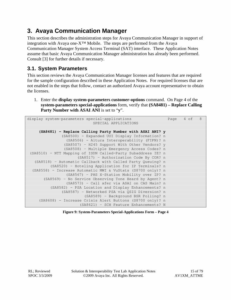
1. Enter the display system-parameters customer-options command. On Page 4 of the system-parameters special-applications form, verify that (SA8481) – Replace Calling Party Number with ASAI ANI is set to “y”.
display system-parameters special-applications Page 4 of 8 SPECIAL APPLICATIONS (SA8481) - Replace Calling Party Number with ASAI ANI? y (SA8500) - Expanded UUI Display Information? n (SA8506) - Altura Interoperability (FIPN)? n (SA8507) - H245 Support With Other Vendors? y (SA8508) - Multiple Emergency Access Codes? n (SA8510) - NTT Mapping of ISDN Called-Party Subaddress IE? n (SA8517) - Authorization Code By COR? n (SA8518) - Automatic Callback with Called Party Queuing? n (SA8520) - Hoteling Application for IP Terminals? n (SA8558) - Increase Automatic MWI & VuStats (S8700 only)? n (SA8567) - PHS X-Station Mobility over IP? n (SA8569) - No Service Observing Tone Heard by Agent? n (SA8573) - Call xfer via ASAI on CAS Main? n (SA8582) - PSA Location and Display Enhancements? n (SA8587) - Networked PSA via QSIG Diversion? n (SA8589) - Background BSR Polling? n (SA8608) - Increase Crisis Alert Buttons (S8700 only)? n (SA8621) - SCH Feature Enhancements? N
Figure 9: System-Parameters Special-Applications Form – Page 4
2. On Page 7 of the system-parameters special-applications form, verify that (SA8931) – Send IE with EC500 Extension Number is set to “y”.
change system-parameters special-applications Page 7 of 8 SPECIAL APPLICATIONS (SA8888) - Per Station Music On Hold? n (SA8889) - Verizon VoiceGenie SIP MIME Message Bodies? n (SA8891) - Verizon VoiceGenie SIP Headers? n (SA8896) - IP Softphone Lamp Control? n (SA8900) - Support for NTT Call Screening? n (SA8904) - Location Based Call Type Analysis? n (SA8911) - Expanded Public Unknown Table? n (SA8917) - LSP Redirect using special coverage point? n (SA8927) - Increase Paging Groups? n (SA8928) - Display Names on Bridged Appearance Labels? n (SA8931) - Send IE with EC500 Extension Number? y (SA8942) - Multiple Unicode Message File Support? n (SA8944) - Multiple Logins for Single IP Address? n (SA8946) - Site Data Expansion? n (SA8957) - PIN Checking for Private Calls? n (SA8958) - Increase BSR Polling/Interflow Pairs to 40000? n (SA8965) - SIP Shuffling with SDP? n (SA8967) - Mask CLI and Station Name for QSIG/ISDN Calls? n (SA8972) - Overwrite Calling Identity? n
Figure 10: System-Parameters Special Applications Form – Page 7
3. Enter the display system-parameters customer-options command. On Page 1 of the system-parameters customer-options form, verify that the Maximum Off-PBX Telephones – EC500 number is sufficient for the number of expected Avaya one-X™ Mobile users (one EC500 license per Avaya one-X™ Mobile user).
display system-parameters customer-options Page 1 of 11 OPTIONAL FEATURES G3 Version: V15 Software Package: Standard Location: 1 RFA System ID (SID): 1 Platform: 6 RFA Module ID (MID): 1 USED Platform Maximum Ports: 44000 286 Maximum Stations: 36000 101 Maximum XMOBILE Stations: 0 0 Maximum Off-PBX Telephones - EC500: 1000 0 Maximum Off-PBX Telephones - OPS: 36000 15 Maximum Off-PBX Telephones - PBFMC: 0 0 Maximum Off-PBX Telephones - PVFMC: 0 0 Maximum Off-PBX Telephones - SCCAN: 0 0
Figure 11: System-Parameters Customer-Options Form – Page 1
4. On Pages 3, 4, and 9 of the system-parameters customer-options form, verify that the bolded fields in the following screenshots are set to “y”.
display system-parameters customer-options Page 3 of 11 OPTIONAL FEATURES Abbreviated Dialing Enhanced List? y Audible Message Waiting? n Access Security Gateway (ASG)? n Authorization Codes? n Analog Trunk Incoming Call ID? y CAS Branch? n A/D Grp/Sys List Dialing Start at 01? y CAS Main? n Answer Supervision by Call Classifier? y Change COR by FAC? n ARS? y Computer Telephony Adjunct Links? y ARS/AAR Partitioning? y Cvg Of Calls Redirected Off-net? y ARS/AAR Dialing without FAC? y DCS (Basic)? y ASAI Link Core Capabilities? y DCS Call Coverage? y ASAI Link Plus Capabilities? y DCS with Rerouting? y Async. Transfer Mode (ATM) PNC? n Async. Transfer Mode (ATM) Trunking? n Digital Loss Plan Modification? y ATM WAN Spare Processor? n DS1 MSP? n ATMS? n DS1 Echo Cancellation? y Attendant Vectoring? y
Figure 12: System-Parameters Customer-Options Form – Page 3
display system-parameters customer-options Page 4 of 11 OPTIONAL FEATURES Emergency Access to Attendant? y IP Stations? y Enable 'dadmin' Login? y Enhanced Conferencing? y ISDN Feature Plus? y Enhanced EC500? y ISDN/SIP Network Call Redirection? y Enterprise Survivable Server? n ISDN-BRI Trunks? y Enterprise Wide Licensing? n ISDN-PRI? y ESS Administration? n Local Survivable Processor? n Extended Cvg/Fwd Admin? y Malicious Call Trace? n External Device Alarm Admin? n Media Encryption Over IP? n Five Port Networks Max Per MCC? n ode Code for Centralized Voice Mail? n Flexible Billing? n Forced Entry of Account Codes? n Multifrequency Signaling? y Global Call Classification? n Multimedia Call Handling (Basic)? y Hospitality (Basic)? y Multimedia Call Handling (Enhanced)? y Hospitality (G3V3 Enhancements)? n Multimedia IP SIP Trunking? n IP Trunks? y IP Attendant Consoles? n
Figure 13: System-Parameters Customer-Options Form – Page 4
display system-parameters customer-options Page 9 of 11 ASAI ENHANCED FEATURES Adjunct Routing? y CTI Stations? y Increased Adjunct Route Capacity? n Phantom Calls? y ASAI PROPRIETARY FEATURES Agent States? n
Figure 14: System-Parameters Customer-Options Form – Page 9
5. On Page 10 of the system-parameters customer-options form, verify that there are sufficient IP_API_A licenses.
display system-parameters customer-options Page 10 of 11 MAXIMUM IP REGISTRATIONS BY PRODUCT ID Product ID Rel. Limit Used IP_API_A : 1000 0 IP_API_B : 1000 0 IP_API_C : 1000 0
Figure 15: System-Parameters Customer-Options Form – Page 10
6. Enter the change system-parameters features command. On Page 4 of the system-parameters features form, set Trunk-to-Trunk Transfer to “all”.
change system-parameters features Page 1 of 17 FEATURE-RELATED SYSTEM PARAMETERS Self Station Display Enabled? n Trunk-to-Trunk Transfer: all Automatic Callback - No Answer Timeout Interval (rings): 3 Call Park Timeout Interval (minutes): 10 Off-Premises Tone Detect Timeout Interval (seconds): 20 AAR/ARS Dial Tone Required? y Music/Tone on Hold: none Music (or Silence) on Transferred Trunk Calls? no DID/Tie/ISDN/SIP Intercept Treatment: attd Internal Auto-Answer of Attd-Extended/Transferred Calls: transferred Automatic Circuit Assurance (ACA) Enabled? n Abbreviated Dial Programming by Assigned Lists? n Auto Abbreviated/Delayed Transition Interval (rings): 2 Protocol for Caller ID Analog Terminals: Bellcore Display Calling Number for Room to Room Caller ID Calls? n
Figure 16: System-Parameters Features Form – Page 1
3.2. Dial Plan and Feature Access Codes This section briefly describes the dial plan requirements and feature access codes for the configuration described in these Application Notes.
1. Enter the change dialplan analysis command to provision the dial plan. Note the following dialed strings administered in Figure 17:
• 3-digit dial access codes (indicated with a Call Type of “dac”) beginning with the digits “1” – Trunk Access Codes (TACs) defined for trunk groups in this configuration conform to this format. • 5-digit extensions (indicated with a Call Type of “ext”) beginning with the digit “2” – extensions for stations, CTI ports, CTI links, voicemail access, etc. in this configuration conform to this format. • Single-digit (“9”) and 3-digit (“*” and “#”) feature access codes (indicated with a Call Type of “fac”) – These dialed strings will be interpreted as Feature Access Codes (FACs). In this configuration, “9” is used as the user-dialed prefix for outbound calls to the PSTN, and 3-digit codes beginning with “*” and “#” are used by Avaya one-X™ Mobile to invoke features described in the next step.
display dialplan analysis Page 1 of 12 DIAL PLAN ANALYSIS TABLE Location: all Percent Full: 2 Dialed Total Call Dialed Total Call Dialed Total Call String Length Type String Length Type String Length Type 1 3 dac 2 5 ext 8 1 fac 9 1 fac * 3 fac # 3 fac
Figure 17: Dialplan Analysis Form
2. Enter the change feature-access-codes command. On Pages 1, 2, and 3 of the feature-access-codes form, provision access codes that are valid under the administered dial plan in Step 1 for the following features: • Auto Route Selection (ARS) - Access Code 1 – In this configuration, ARS is used for routing calls to the PSTN, and the access code (“9” in Figure 18) entered here is used as the user-dialed prefix for outbound calls. See Section 3.5.1 for further details on outbound call routing administration. • EC500 Self-Administration Access Code – Avaya one-X™ Mobile uses this FAC to provision a mapping in Avaya Communication Manager between a user’s office extension and the user’s mobile phone number. • Enhanced EC500 Activation and Deactivation - Avaya one-X™ Mobile uses this FAC on a per call basis to activate/deactivate “Simulring” calls to a user’s mobile phone number.
• Send All Calls Activation and Deactivation - Avaya one-X™ Mobile uses this FAC to activate/deactivate the sending of a user’s inbound calls to call coverage, i.e., to the user’s corporate voice mailbox.
change feature-access-codes Page 3 of 9 FEATURE ACCESS CODE (FAC) Leave Word Calling Send A Message: Leave Word Calling Cancel A Message: Limit Number of Concurrent Calls Activation: Deactivation: Malicious Call Trace Activation: Deactivation: Meet-me Conference Access Code Change: PASTE (Display PBX data on Phone) Access Code: Personal Station Access (PSA) Associate Code: Dissociate Code: Per Call CPN Blocking Code Access Code: Per Call CPN Unblocking Code Access Code: Priority Calling Access Code: Program Access Code: Refresh Terminal Parameters Access Code: Remote Send All Calls Activation: Deactivation: Self Station Display Activation: Send All Calls Activation: *80 Deactivation: #80 Station Firmware Download Access Code:
Figure 20: Feature-Access-Codes Form – Page 3
3.3. Class of Restriction and Class of Service This section briefly discusses the Class of Restriction (COR) and Class of Service (COS) used in this configuration. In general, COR and COS are used to define and restrict call and feature privileges. Note that there can be different customer reasons and strategies in administering and assigning various Classes of Restriction and Classes of Service in actual deployments, but that is beyond the scope of these Application Notes. Consult [4] for further details. For simplicity, a single COR and single COS is used throughout this configuration. Enter the change cor r command, where r is the number of an unused Class of Restriction. On Page 1 of the cor form, assign an FRL (Facility Restriction Level) between 0 and 7, with 0 being the least restrictive, and set Calling Party Restriction and Called Party Restriction to “none”. For simplicity, an FRL of 0 is used in this configuration.
change cor 1 Page 1 of 23 CLASS OF RESTRICTION COR Number: 1 COR Description: FRL: 0 APLT? y Can Be Service Observed? y Calling Party Restriction: none Can Be A Service Observer? y Called Party Restriction: none Partitioned Group Number: 1 Forced Entry of Account Codes? n Priority Queuing? n Direct Agent Calling? y Restriction Override: none Facility Access Trunk Test? n Restricted Call List? n Can Change Coverage? n Access to MCT? y Fully Restricted Service? n Group II Category For MFC: 7 Hear VDN of Origin Annc.? y Send ANI for MFE? n Add/Remove Agent Skills? n MF ANI Prefix: Automatic Charge Display? n Hear System Music on Hold? y PASTE (Display PBX Data on Phone)? n Can Be Picked Up By Directed Call Pickup? y Can Use Directed Call Pickup? y Group Controlled Restriction: inactive
Figure 21: COR Form – Page 1 COS 1 is used in this configuration (may vary according to customer requirements). Consult [3] for descriptions of the COS feature permissions. change cos Page 1 of 2 CLASS OF SERVICE 0 1 2 3 4 5 6 7 8 9 10 11 12 13 14 15 Auto Callback n y y n y n y n y n y n y n y n Call Fwd-All Calls n y n y y n n y y n n y y n n y Data Privacy n y n n n y y y y n n n n y y y Priority Calling n y n n n n n n n y y y y y y y Console Permissions n y n n n n n n n n n n n n n n Off-hook Alert n n n n n n n n n n n n n n n n Client Room n n n n n n n n n n n n n n n n Restrict Call Fwd-Off Net n n y y y y y y y y y y y y y y Call Forwarding Busy/DA n y n n n n n n n n n n n n n n Personal Station Access (PSA) n n n n n n n n n n n n n n n n Extended Forwarding All n y n n n n n n n n n n n n n n Extended Forwarding B/DA n y n n n n n n n n n n n n n n Trk-to-Trk Transfer Override n y n n n n n n n n n n n n n n QSIG Call Offer Originations n n n n n n n n n n n n n n n n Contact Closure Activation n n n n n n n n n n n n n n n n
3.4. ISDN-PRI Trunk In this configuration, an ISDN-PRI trunk is used for both inbound Direct Inward Dialing (DID) calls from, and outbound calls to, the PSTN. Since the ISDN-PRI trunk administration can vary according to customer needs and the ISDN-PRI trunk service offered in a given locale, consult [3] for details on ISDN-PRI trunk administration options. This section briefly describes the administration options relevant to this configuration. Enter the change trunk-group t command, where t is the number of an ISDN-PRI trunk group. On Pages 2 and 3 of the trunk-group form, set the bolded fields in Figure 23 and Figure 24 to the values shown.
change trunk-group 99 Page 2 of 21 Group Type: isdn TRUNK PARAMETERS Codeset to Send Display: 6 Codeset to Send National IEs: 6 Max Message Size to Send: 260 Charge Advice: none Supplementary Service Protocol: a Digit Handling (in/out): enbloc/enbloc Trunk Hunt: cyclical Digital Loss Group: 13 Incoming Calling Number - Delete: Insert: Format: Bit Rate: 1200 Synchronization: async Duplex: full Disconnect Supervision - In? y Out? y Answer Supervision Timeout: 0 Administer Timers? n CONNECT Reliable When Call Leaves ISDN? n
Figure 23: Trunk-Group Form – Page 2 change trunk-group 99 Page 3 of 21 TRUNK FEATURES ACA Assignment? n Measured: none Wideband Support? n Internal Alert? n Maintenance Tests? y Data Restriction? n NCA-TSC Trunk Member: Send Name: y Send Calling Number: y Used for DCS? n Send EMU Visitor CPN? n Suppress # Outpulsing? n Format: public Outgoing Channel ID Encoding: preferred UUI IE Treatment: service-provider Replace Restricted Numbers? n Replace Unavailable Numbers? n Send Connected Number: y Network Call Redirection: none Hold/Unhold Notifications? y Send UUI IE? y Modify Tandem Calling Number? n Send UCID? n Send Codeset 6/7 LAI IE? y Ds1 Echo Cancellation? n Apply Local Ringback? n US NI Delayed Calling Name Update? n Show ANSWERED BY on Display? y Network (Japan) Needs Connect Before Disconnect? n
3.5. PSTN Call Routing This section describes the steps for administering outbound and inbound PSTN call routing on Avaya Communication Manager. In this configuration, each user is assigned a DID number as shown in Table 2. Note that these Application Notes uses North American (10-digit numbers with a leading “1” as the country code where necessary) numbering in all calling and called number examples that follow.
User Extension User DID (Business Number) 20001 732-552-2747 20002 732-552-2748 20003 732-552-2749 20004 732-552-2948
Table 2: User Extension and User DID Association
3.5.1. Outbound Calls This section describes the steps for administering the routing of outbound calls to the PSTN. In this configuration, ARS is used to route outbound calls via the ISDN-PRI trunk described in Section 3.4 to the PSTN. Outbound call routing is used in the following situations: • Calls placed by an Avaya Communication Manager phone (e.g., an office phone) to PSTN phone numbers. • “Simulring” calls to receive (“Send Calls”) destinations, e.g., mobile phone, home phone, other landline phones, etc., selected by an Avaya one-X™ Mobile user for inbound business calls. • “Callback” calls from Avaya Communication Manager to the phone, e.g., mobile phone, home phone, other landline phone, etc., selected by an Avaya one-X™ Mobile user for originating a call.
1. Enter the change ars digit-conversion x command. In the ars digit-conversion form, provision entries as shown in bold in Figure 25. The first entry matches dialed 10-digit numbers that are in the “home” area code of the enterprise office, i.e., same area code as the DID / business numbers assigned to the enterprise office, and directs such calls to be then handled by ARS routing without any modification to the dialed 10-digit numbers. Note that this entry varies according to the customer location. The second entry prefixes a leading “1” to all other dialed 10-digit numbers and directs such calls to be then handled by ARS routing.
change ars digit-conversion x Page 1 of 2 ARS DIGIT CONVERSION TABLE Location: all Percent Full: 1 Matching Pattern Min Max Del Replacement String Net Conv ANI Req 732 10 10 0 ars n n x 10 10 0 1 ars n n
2. Enter the change ars analysis d command, where d is any digit(s). In the ars digit-
conversion form, provision an entry for each PSTN destination as follows: • Dialed String – Enter the leading digits of a dialed PSTN destination, e.g., 1 followed by the destination area code. • Total Min and Max – Enter “11”. • Route Pattern – Enter the number of an unused route pattern. • Call Type – Enter “fnpa”. Note: Enterprise users, by habit, accident, or other reasons, might still dial a leading “1” to all PSTN destinations, even destination numbers in the “home” area code of the enterprise office. For that reason, an entry to cover this case should also be provisioned as above. In addition, provision another entry to cover the case where enterprise users dial PSTN destinations in the “home” area code of the enterprise office without a leading “1”. For this entry, set Dialed String to the leading digits of the dialed PSTN destination, e.g., the “home” area code, Total Min and Max to “10”, Route Pattern to the same route pattern as above, and Call Type to “hnpa”.
change ars analysis 1732 Page 2 of 2 ARS DIGIT ANALYSIS TABLE Location: all Percent Full: 2 Dialed Total Route Call Node ANI String Min Max Pattern Type Num Reqd 1732 11 11 99 hnpa n 1908 11 11 99 fnpa n 1404 11 11 99 fnpa n 732 10 10 99 hnpa n
Figure 26: ARS Analysis Form
In Figure 26, entries are shown for outbound calls to 732-xxx-xxxx, 1-732-xxx-xxxx, 1-908-xxx-xxxx and 1-404-xxx-xxxxx. Typical deployments generally require additional entries, or the use of less exact or wildcard matching strings, to cover all permitted PSTN destination numbers, but that is beyond the scope of these Application Notes. Ensure that there are entries to cover all permitted PSTN destination numbers, including those of the mobile phones and other receive destinations. Consult [3] and [4] for further information on ARS administration.
3. Enter the change route-pattern r command, where r is the route pattern entered in Step
2. Provision an entry as follows: • Grp No - Enter the number of the ISDN-PRI trunk group described in Section 3.4. • FRL - Enter the minimum Facility Restriction Level necessary to use this trunk group, with 0 being the least restrictive. Set this FRL to a value less than or equal to the FRL of the COR administered in Section 3.3 and assigned to the stations in Section 3.9 Step 1. • Pfx Mrk – Enter “1”.
change route-pattern 99 Page 1 of 3 Pattern Number: 99 Pattern Name: Out to PSTN SCCAN? n Secure SIP? n Grp FRL NPA Pfx Hop Toll No. Inserted DCS/ IXC No Mrk Lmt List Del Digits QSIG Dgts Intw 1: 99 0 1 n user 2: n user 3: n user 4: n user 5: n user 6: n user
Figure 27: Route-Pattern Form
4. Enter the change public-unknown numbering 0 command to specify the calling party numbers sent on outbound calls on the ISDN-PRI trunk. In the public-unknown numbering form, provision an entry as follows: • Ext Len - enter the extension length, e.g., “5” since 5-digit extensions are used in this configuration. • For deployments where users’ extensions and users’ business numbers share a common suffix2, enter enough leading digits to identify a user extension range for Ext Code. In addition, enter enough prefix digits for CPN Prefix to form the business numbers, i.e., the CPN Prefix will be prefixed to the extension to form the complete business number. Note that this entry would then be valid for multiple users, i.e., those in the same extension range. For example, if a deployment uses extensions 31xxx and business numbers 212-553-1xxx, then set Ext Code to “31” and CPN Prefix to “21255” or “121255” (depending on whether 10- or 11-digit calling party numbers are to be sent). As another example, if a deployment uses extensions 31xxx and business numbers 212-550-1xxx, then set Ext Code to “31” and CPN Prefix to “212550” or “1212550” (the “0” overwrites the “3”). • For deployments where users’ extensions and users’ business numbers do not share a common suffix, as in Figure 28, enter a user’s entire extension for Ext Code, and enter the user’s business number for CPN Prefix. Note that this entry would then be valid for a single user, and as such, additional similar entries must be configured for all other users. • Trk Grp(s) - Enter the number of the ISDN-PRI trunk group described in Section 3.4. • Total CPN Len - Enter the total length of the calling party number to be sent. Provision as many entries as necessary to cover all user extensions / extension ranges.
2 For example:
• Extensions 31xxx and business number 732-553-1xxx share a common suffix 31xxx. • Extensions 31xxx and business number 732-550-1xxx share a common suffix 1xxx. • Extensions 31xxx and business number 732-531-xxx0 do NOT share a common suffix.
change public-unknown-numbering 0 Page 1 of 2 NUMBERING - PUBLIC/UNKNOWN FORMAT Total Ext Ext Trk CPN CPN Len Code Grp(s) Prefix Len Total Administered: 63 5 20001 99 7325522747 10 Maximum Entries: 9999 5 20002 99 7325522748 10 5 20003 99 7325522749 10 5 20004 99 7325522948 10
Figure 28: Public-Unknown Numbering Form
3.5.2. Inbound Calls This section describes the steps for administering the routing of inbound DID calls to Avaya Communication Manager extensions. Once a DID call is routed to an extension, if that extension is also that of an Avaya one-X™ Mobile user, then Avaya one-X™ Mobile instructs Avaya Communication Manager to route the call to all of the receive (“Send Calls”) destinations selected by the user. For the receive destinations that are in the PSTN (e.g., mobile and/or landlines), those calls are routed according to the outbound call routing described in Section 3.5.1. The procedures for which a user specifies and selects receive destinations is described in the one-X™ Mobile User Guides [7], [8], and [9]. In this configuration, inbound calls from the PSTN arrive via the ISDN-PRI trunk described in Section 3.4. Enter the change inc-call-handling-trmt trunk-group t command, where t is the number of the trunk group described in Section 3.4, to specify how the called party numbers on inbound calls on the ISDN-PRI trunk are to be interpreted. In the inc-call-handling-trmt trunk-group form, provision an entry as follows: • Called Len – Enter the total number of digits in the called party number. • For deployments where users’ extensions and users’ business numbers share a common suffix, enter enough leading digits to uniquely match a business number range for Called Number. In addition, for Del, enter the total number of leading business number digits that need to be deleted in order to arrive at the common suffix, and for Insert, if necessary enter the leading digit(s) to be prefixed to the suffix in order to arrive at the extension. Note that this entry would then be valid for multiple business numbers, i.e., those in the same business number range. For example, if a deployment uses business numbers 212-553-1xxx and extensions 31xxx, then set Called Number to “2125531” and Del to “5”. As another example, if a deployment uses business numbers 212-550-1xxx and extensions 31xxx, then set Called Number to “2125501”, Del to “6”, and Insert to “3”. • For deployments where users’ extensions and users’ business numbers do not share a common suffix, as in Figure 29, enter a user’s business number for Called Number, the total number of digits in the business number for Del, and the user’s extension for Insert. Note that this entry would then be valid for a single business number, and as such, additional similar entries must be configured for every other business number. Provision as many entries as necessary to cover all users’ business numbers / number ranges.
change inc-call-handling-trmt trunk-group 99 Page 1 of 30 Service/ Called Called Del Insert Per Call Night Feature Len Number CPN/BN Serv public-ntwrk 10 7328522747 10 20001 public-ntwrk 10 7328522748 10 20002 public-ntwrk 10 7328522749 10 20003 public-ntwrk 10 7328522948 10 20004
Figure 29: Inc-Call-Handling-Trmt Trunk-Group Form
3.6. CTI Connection with Avaya AE Services This section describes the steps for the administering the Avaya Communication Manager side of a CTI connection with Avaya AE Services.
1. Enter the add cti-link c command, where c is the number of an unused CTI link. On Page 1 of the cti-link form, provision the following: • Extension – Enter an unused extension valid under the administered dial plan. • Type – Set to “ADJ-IP”. • COR – Set to the Class of Restriction administered in Section 3.3.
add cti-link 1 Page 1 of 3 CTI LINK CTI Link: 1 Extension: 29901 Type: ADJ-IP COR: 1 Name:
Figure 30: CTI-Link Form – Page 1
2. Enter the list node-names command and note the Node Name and IP address of a C-LAN board that has IP connectivity to the Avaya AE Services server.
list node-names Page 1 NODE NAMES Type Name IP Address IP clan 10.160.179.112 IP clan-01a08 10.160.179.108 IP crossfire 10.160.179.114 IP default 0.0.0.0 IP medpro-hw11 10.160.179.116 IP procr 10.160.179.103
Figure 31: Node-Names Form
3. Enter the change ip-services command. On Page 1 of the ip-services form, provision an entry as shown in Figure 32. Note that Local Node is the Node Name of a C-LAN board noted in Step 2. For Avaya media gateways without C-LAN boards, enter “procr”.
change ip-services Page 1 of 4 IP SERVICES Service Enabled Local Local Remote Remote Type Node Port Node Port AESVCS y clan-01a08 8765
Figure 32: IP-Services Form – Page 1
4. On Page 4 of the ip-services form, provision an entry as shown in Figure 33. Note that
the AE Services Server value must match the hostname of the Avaya AE Services server and the Password must match the password provisioned on the Avaya AE Services Switch Connection in Section 4 Step 2.
change ip-services Page 4 of 4 AE Services Administration Server ID AE Services Password Enabled Status Server 1: aes1 aespassword123 y
Figure 33: IP-Services Form – Page 4
3.7. Voicemail In this configuration, Avaya Modular Messaging is used as the enterprise voice messaging platform. The integration of Avaya Communication Manager with Avaya Modular Messaging is beyond the scope of these Application Notes. Consult http://support.avaya.com/japple/css/japple?PAGE=Product&temp.productID=151670 for further information.
3.8. Configuration Set Enter the change off-pbx-telephone configuration-set o command, where o is the number of an unused configuration set, and set the bolded fields in Figure 34 to the values shown. change off-pbx-telephone configuration-set 2 Page 1 of 1 CONFIGURATION SET: 2 Configuration Set Description: AT&T 1XM w/ ConfAnsw Calling Number Style: network CDR for Origination: phone-number CDR for Calls to EC500 Destination? y Fast Connect on Origination? n Post Connect Dialing Options: dtmf Cellular Voice Mail Detection: timed (seconds): 1 Barge-in Tone? n Calling Number Verification? y Call Appearance Selection for Origination: primary-first Confirmed Answer? y Timeout (seconds): 10
Figure 34: Off-PBX-Telephone Configuration-Set Form
3.9. Configuration for Avaya one-X™ Mobile Users This section describes the steps for enabling Avaya Communication Manager stations (users) with Avaya one-X™ Mobile functionality. The steps assume existing stations, though for new stations, the commands below are simply “add” rather than “change” commands. Consult [3] for further information on administering new stations in Avaya Communication Manager.
1. Enter the change station e command, where e is the office extension of a user to be enabled with Avaya one-X™ Mobile. On Page 1 of the station form, ensure that a Coverage Path is assigned (e.g., “1” in Figure 35 below). Coverage paths are typically used to allow inbound calls to a station to be redirected to other extensions, e.g., voicemail, when the station does not answer. The administration of call coverage is beyond the scope of these Application Notes. Consult [3] and [4] for further details.
change station 20001 Page 1 of 5 STATION Extension: 20001 Lock Messages? n BCC: 0 Type: 4610 Security Code: * TN: 1 Port: S00054 Coverage Path 1: 1 COR: 1 Name: Abby M. Eatontown Coverage Path 2: COS: 1 Hunt-to Station: STATION OPTIONS Time of Day Lock Table: Loss Group: 19 Personalized Ringing Pattern: 1 Message Lamp Ext: 20001 Speakerphone: 2-way Mute Button Enabled? y Display Language: english Survivable GK Node Name: Survivable COR: internal Media Complex Ext: Survivable Trunk Dest? y IP SoftPhone? n Customizable Labels? y
Figure 35: Station Form – Page 1
2. On Page 2 of the station form, consider the following. The default Restrict Last Appearance of “y” reserves one call appearance for outbound calls only; in other words, if all but one call appearance is occupied, the remaining call appearance may be used for outbound calling only. Setting Restrict Last Appearance to “n” allows the remaining appearance to be used for other calls, such as inbound calls. The decision to change this setting from the default is a customer preference.
change station 20001 Page 2 of 5 STATION FEATURE OPTIONS LWC Reception: spe Auto Select Any Idle Appearance? n LWC Activation? y Coverage Msg Retrieval? y LWC Log External Calls? n Auto Answer: none CDR Privacy? n Data Restriction? n Redirect Notification? y Idle Appearance Preference? n Per Button Ring Control? n Bridged Idle Line Preference? n Bridged Call Alerting? n Restrict Last Appearance? y Active Station Ringing: single EMU Login Allowed? n H.320 Conversion? n Peration CPN - Send Calling Number? Service Link Mode: as-needed Multimedia Mode: enhanced MWI Served User Type: sip-adjunct Display Client Redirection? n Select Last Used Appearance? n Coverage After Forwarding? s Multimedia Early Answer? n Direct IP-IP Audio Connections? y Emergency Location Ext: 20001 Always Use? n IP Audio Hairpinning? n
Figure 36: Station Form – Page 2
3. On Pages 4 (and/or 5 if necessary) of the station form, provision at least five “call-appr” buttons and one “extend-call” button. Provision an additional “call-appr” button if Restrict Last Appearance in Step 2 is set to “y”.
change station 20001 Page 4 of 5 STATION SITE DATA Room: Headset? n Jack: Speaker? n Cable: Mounting: d Floor: Cord Length: 0 Building: Set Color: ABBREVIATED DIALING List1: List2: List3: BUTTON ASSIGNMENTS 1: call-appr 5: call-appr 2: call-appr 6: call-appr 3: call-appr 7: extnd-call 4: call-appr 8:
Figure 37: Station Form – Page 4
4. Enter the change off-pbx-telephone station-mapping e command, where e is the local extension of the user modified in Steps 1 - 3. On Page 1 of the off-pbx-telephone
station-mapping form, set the bolded fields to the values shown in Figure 38. Note that the Config Set is the configuration set configured in Section 3.8. Phone Number may be configured with the user’s mobile phone number or left blank if the number is not yet known (Avaya one-X™ Mobile will automatically provision this number after the user enters a mobile phone number in Avaya one-X™ Mobile Web (see [6]).
change off-pbx-telephone station-mapping 20001 Page 1 of 2 STATIONS WITH OFF-PBX TELEPHONE INTEGRATION Station Application Dial CC Phone Number Trunk Config Extension Prefix Selection Set 20001 EC500 - ars 2
Figure 38: Off-PBX-Telephone Station-Mapping Form – Page 1
5. On Page 2 of the off-pbx-telephone station-mapping form, set the bolded fields in Figure 39 to the values shown.
change off-pbx-telephone station-mapping 20001 Page 2 of 2 STATIONS WITH OFF-PBX TELEPHONE INTEGRATION Station Call Mapping Calls Bridged Location Exten Limit Mode Allowed Calls sion 20001 2 both all both
Figure 39: Off-PBX –Telephone Station-Mapping Form – Page 2
6. Repeat Steps 1 – 4 for each user to be enabled with Avaya one-X™ Mobile.
3.10. Allow SAT Access for Avaya one-X™ Mobile 1. Launch a web browser, enter http://<IP address of Avaya Communication Manager
server> in the URL, and log in with the appropriate credentials. Click on “Launch Maintenance Web Interface”.
Figure 40: Avaya Communication Manager Web Interface
4. Avaya Application Enablement (AE) Services This section describes the administration steps for Avaya Application Enablement (AE) Services in support of integration with Avaya one-X™ Mobile. These Application Notes assume that basic Avaya AE Services administration has already been performed. Consult [5] for further details if necessary.
4.1. Licensed Features This section reviews the Avaya AE Services licensed features that are required for the sample configuration described in these Application Notes. For required licenses that are not enabled in the steps that follow, contact an authorized Avaya account representative to obtain the licenses.
1. Launch a web browser, enter https://<IP address of Avaya AE Services server/WebLM/index.jsp> in the URL, and log in with the appropriate credentials.
2. In the left pane, click on Licensed Products Application_Enablement and verify that the following features are licensed: • Application Enablement Connections (VALUE_AEC_CONNECTIONS) • TSAPI Version (VALUE_TSAPI_VERSION) • Application Enablement Connections Version (VALUE_AEC_VERSION) • TSAPI Simultaneous Users (VALUE_TSAPI_USERS) • CVLAN Version (VALUE_CVLAN_VERSION) • Product Notes (VALUE_NOTES)
4.2. DMCC and JTAPI Users This section describes the steps for administering the DMCC and JTAPI user accounts to be used by Avaya one-X™ Mobile. 1. Launch a web browser, enter https://<IP address of Avaya AE Services
server/MVAP/index.jsp> in the URL, and log in with the appropriate credentials. In the left pane, click on User Management.
2. In the left pane, click on User Management Add User. In the Add User page, enter
values for the required fields (marked with asterisks) and set CTI User to “Yes”. Scroll down to the bottom of the page and click on “Apply”. This user will be used by Avaya one-X™ Mobile in Section 7.2.2 Step 3 for DMCC purposes.
Figure 47: Add User Page
3. Repeat Step 2 to create another user. This user will be used by Avaya one-X™ Mobile in
Section 7.2.2 Step 3 for JTAPI purposes.
4. Click on OAM Home in the upper right corner of the page to return to the Avaya AE Services OAM home page.
4.3. Enabling DMCC Ports This section describes the steps for enabling the Avaya AE Services server ports to allow Avaya one-X™ Mobile to access the DMCC service On Avaya AE Services.
1. In the left pane, click on CTI OAM Administration.
Figure 49: AE Services OAM Home Page
2. In the left pane, click on Administration Network Configuration Ports. In the
Ports page, in the DMCC Server Ports section, enable Unencrypted Port 4721 and Encrypted Port 4722. Scroll down to the bottom page and click on “Apply Changes”.
3. In the Apply Changes to Port Properties page, click on “Apply” to confirm the
changes.
Figure 51: Apply Changes to Port Properties Page
4.4. Switch Connections and CTI Connections This section describes the steps for the administering the Avaya AE Services side of a CTI connection with Avaya Communication Manager.
1. In the left pane, click on Administration Switch Connections. In the Switch Connections page, enter a descriptive name in the textbox and click on “Add Connection”. A Switch Connection on Avaya AE Services defines a connection to an Avaya Communication Manager.
Figure 52: Switch Connections Page
2. In the Set Password page, enter a password for Switch Password and Confirm Switch
Password. The password must match the password configured on the Avaya Communication Manager ip-services form in Section 3.6 Step 4. Click on “Apply”.
Figure 53: Set Password Page
3. After returning to the Switch Connections page, select the radio button corresponding to
the Switch Connection administered in Steps 1 - 2, and click on “Edit CLAN IPs”.
4. In the Edit CLAN IPs page, enter the IP address of the Avaya Communication Manager
C-LAN board enabled with AESVCS in Section 3.6 Steps 2 - 3, and click on “Add Name or IP”.
Figure 55: Edit CLAN IPs Page
5. In the left pane, click on Administration CTI Link Admin TSAPI Links. In the
TSAPI Links page, click on “Add Link”.
Figure 56: TSAPI Links Page
6. In the Add / Edit TSAPI Links page, provision the following fields and click on “Apply
Changes”: • Link – Select any unused link number. • Switch Connection – Select the Switch Connection administered in Steps 1 - 2. • Switch CTI Link Number – Select the number of the Avaya Communication
Manager CTI link administered in Section 3.6 Step 1.
7. In the Apply Changes to Link page, click on “Apply” to confirm the changes.
Figure 58: Apply Changes to Link Page
4.5. Security Database This section describes the steps for administering Avaya AE Services security database privileges.
1. In the left pane, click on Administration Security Database SDB Control. In the SDB Control for DMCC and TSAPI page, check the Enable SDB Service, JTAPI, and Telephony Service checkbox, and click on “Apply Changes”.
Figure 59: SDB Control for DMCC and TSAPI Page
2. In the left pane, click on Administration Security Database CTI Users List
All Users. In the CTI Users page, select the DMCC user administered in Section 4.2 Step 2 and click on “Edit”.
5. Repeat Steps 2 - 4 for the JTAPI user administered in Section 4.2 Step 3.
4.6. [Optional] Dial Plan Settings This section describes the administration of Avaya AE Services Dial Plan rules that Avaya one-X™ Mobile can use to convert users’ LDAP telephone numbers to users’ extensions when importing users into Avaya one-X™ Mobile (see Section 7.4). However, SKIP this section if either of the following is true: 1) The customer elects to use the Avaya one-X™ Mobile algorithm described in Section 7.2.5
Step 4 to convert users’ LDAP telephone numbers to users’ extensions. 2) The users’ extensions and the users’ LDAP telephone numbers do NOT share a common
suffix, i.e., do NOT have common trailing digits. For example: o Extensions 31xxx and LDAP telephone numbers +17325531xxx share a common
suffix 31xxx. Therefore, this section may be implemented for this set of extensions and LDAP telephone numbers.
o Extensions 31xxx and LDAP telephone numbers +17325501xxx share a common suffix 1xxx. Therefore, this section may be implemented for this set of extensions and LDAP telephone numbers.
o Extensions 31xxx and LDAP telephone numbers +1732531xxx0 do NOT share a common suffix. Therefore, this section must be skipped for this set of extensions and LDAP telephone numbers.
1. In the left pane, click on Administration Dial Plan Switch Administration. In
the Switch Dial Plan Administration, select the radio button corresponding to the Switch Connection administered in Section 4.4 Steps 1 - 2 and click on “Detail”.
Figure 63: Switch Dial Plan Administration Page
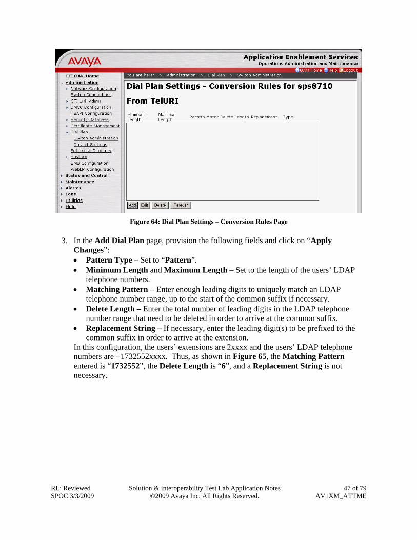
2. In the Dial Plan Settings – Conversion Rules page, in the From TelURI section, click on “Add”.
Figure 64: Dial Plan Settings – Conversion Rules Page
3. In the Add Dial Plan page, provision the following fields and click on “Apply
Changes”: • Pattern Type – Set to “Pattern”. • Minimum Length and Maximum Length – Set to the length of the users’ LDAP
telephone numbers. • Matching Pattern – Enter enough leading digits to uniquely match an LDAP
telephone number range, up to the start of the common suffix if necessary. • Delete Length – Enter the total number of leading digits in the LDAP telephone
number range that need to be deleted in order to arrive at the common suffix. • Replacement String – If necessary, enter the leading digit(s) to be prefixed to the
common suffix in order to arrive at the extension. In this configuration, the users’ extensions are 2xxxx and the users’ LDAP telephone numbers are +1732552xxxx. Thus, as shown in Figure 65, the Matching Pattern entered is “1732552”, the Delete Length is “6”, and a Replacement String is not necessary.
As another example, if the users’ extensions are 31xxx and the users’ LDAP telephone numbers are +17325501xxx, then the Matching Pattern can be “17325501”, the Delete Length is “7”, and the Replacement String is “3”.
4. In the Add Dial Plan confirmation page, click on “Apply” to confirm the changes.
Figure 66: Add Dial Plan – Confirmation Page
5. Repeat Steps 2- 4 as necessary to administer Avaya AE Services Dial Plan rules to cover
all users’ LDAP telephone number ranges.
4.7. SMS Consult [2] for the administration steps to allow Avaya one-X™ Mobile to access the SMS interface on the Avaya AE Services server.
4.8. Restart Avaya AE Services Server In the left pane, click on Maintenance Service Controller. In the Service Controller page, click on “Restart AE Server”.
5. Avaya Modular Messaging with MSS This section describes the administration steps for Avaya Modular Messaging with Message Storage Server (MSS) in support of integration with Avaya one-X™ Mobile. These Application Notes assume that basic Avaya Modular Messaging administration, including user voice mailboxes, has already been performed. These Application Notes also assume that the Avaya Modular Messaging servers (MAS and MSS) and the Avaya one-X™ Mobile server(s) utilize a common timing reference, e.g., an NTP server. Consult http://support.avaya.com/japple/css/japple?PAGE=Product&temp.productID=151670 for further details if necessary.
1. Launch a web browser, enter https://<IP address of Avaya MSS Server> in the URL, and log in with the appropriate credentials. In the left pane under Messaging Administration, click on System Administration. In the Administer System Attribute and Ports page, provision the following fields and click on “Save”: • LDAP Port – Set to “Authenticated or Anonymous”. • IMAP4 Port – Use the default port “143” and set to “Enabled”. • IMAP4 SSL Port – Use the default port “993” and set to “Enabled”. • SMTP Port – Use the default port “25” and set to “Enabled”.
Figure 68: Administer System Attribute and Ports Page
2. In the left pane under Messaging Administration, click on Trusted Server. In the
Manage Trusted Servers page, click on “Add a New Trusted Server”.
3. In the Add Trusted Server page, provision the following and click on “Save”:
• Trusted Server Name – Enter a descriptive name. This name must match the Trusted Server Name provisioned in the Avaya one-X™ Mobile Voicemail Profile in Section 7.2.3 Steps 1 - 2.
• Password and Confirm Password – This password must match the Trusted Server Password provisioned in the Avaya one-X™ Mobile Voicemail Profile in Section 7.2.3 Steps 1 - 2.
• Machine Name / IP Address – Enter the IP address of the internal Avaya one-X™ Mobile server.
• Service Name – Enter “Edge”. • LDAP Access Allowed and IMAP4 Super User Access Allowed – Set to “yes”. • LDAP Connection Security – Set to “No encryption required”. • IMAP4 Super User Connection Security – Set to “Must use SSL or encrypted
6. Microsoft Active Directory In this configuration, Microsoft Active Directory is used as the LDAP server. This section describes the administration of users’ business numbers, and extensions if necessary, in Microsoft Active Directory.
1. On the Microsoft Active Directory server, launch the Active Directory Users and Computers snap-in. Right-click on a user account and select Properties. In the user’s Properties window, enter the user’s DID number as an E.164-formatted number in the Telephone number textbox. In addition, if the user’s extension and the user’s DID number do NOT share a common suffix, then click on “Other”. Otherwise, click on “OK” and skip the remaining steps in this section.
Figure 71: User Properties Window
2. In the Phone Number (Others) window, enter the user’s extension in the New Value
7. Avaya one-X™ Mobile This section describes the administration steps for Avaya one-X™ Mobile integration with Avaya Communication Manager, Avaya AE Services, and Avaya Modular Messaging with MSS. These Application Notes assume that basic Avaya one-X™ Mobile installation and administration has already been performed. Consult [1] and [2] for further details if necessary.
7.1. Licenses Launch a web browser, enter https://<IP Address of internal Avaya one-X™ Mobile server>/Admin in the URL, and log in with the appropriate credentials. Select the Status tab, and verify that there are sufficient licenses. If not, contact an authorized Avaya account representative to obtain the licenses.
Figure 74: Status Tab
7.2. Profiles This section describes the steps for creating profiles on Avaya one-X™ Mobile. The profiles are used for integration with LDAP servers, Avaya Communication Manager, Avaya AE Services, and Avaya Modular Messaging.
7.2.1. Provisioning Profile A Provisioning Profile defines the parameters for importing user information from an LDAP server.
1. Select the Avaya Setup Setup Profiles Provisioning Profile tab, and click on “New Provisioning Profile”.
2. In the New Provisioning Profile page, click on “Show Advanced Settings” and
provision the following: • Profile Name – Enter a descriptive profile name. • Ldap Search Type – Select the appropriate LDAP type. In this configuration,
“Active Directory” is used. • LDAP User DN – Enter the LDAP Distinguished Name (DN) of a user with
permissions to search the LDAP directory. For example, in this configuration, “cn=Administrator,cn=users,dc=spdevcon,dc=com” is entered.
• LDAP Hostname – Enter the IP address of the LDAP server. • LDAP Port Number – Enter the LDAP server port, typically “389”. • LDAP Password – Enter the password of the LDAP user above. • LDAP Base DN – Enter the base search DN. For example, in this configuration,
“cn= users,dc=spdevcon,dc=com” is entered. • Extension – If the users’ extensions and the users’ LDAP telephone numbers do
NOT share a common suffix, i.e., do NOT have common trailing digits, set to the LDAP attribute that contains the extension information. For example, in this configuration, the Active Directory attribute “otherTelephone” (see Section 6 Step 2) is entered. Otherwise, leave the default “telephoneNumber” as entered.
• First Name – Enter the LDAP attribute corresponding to the user’s first name. For Active Directory, enter “givenName”.
7.2.2. CTI Profile A CTI Profile defines the parameters for connecting to the Avaya AE Services server and Avaya Communication Manager to manage inbound and outbound calls for Avaya one-X™ Mobile users.
1. Select the Avaya Setup Setup Profiles CTI Profile tab, and click on “New CTI Profile”.
7.2.3. Voicemail Profile A Voicemail Profile defines the parameters for connecting to the Avaya Modular Messaging MSS server to retrieve corporate voice mailbox information for Avaya one-X™ Mobile users.
1. Select the Avaya Setup Setup Profiles Voicemail Profile tab, and click on “New Voicemail Profile”.
2. In the New Voicemail Profile page, provision the following and click on “Save”:
• Profile Name – Enter a descriptive profile name. • Profile Type – Select the appropriate Avaya Modular Messaging integration. In this
configuration, “Modular Messaging with MSS” is used. • Voicemail Platform Hostname – Enter the IP address of the Avaya MSS server. • IMAP Port – Enter the IMAP4 SSL port provisioned in Section 5 Step 1. • Trusted Server Name and Trusted Server Password – Enter the Trusted Server
Name and Password provisioned in Section 5 Steps 2 - 3. • LDAP User DN – Enter the LDAP DN of the Trusted Server Name above. For
example, in this configuration, “cn=1XMINT,dc=Avaya” is entered, where “1XMINT” is the Trusted Server Name above.
• LDAP Hostname – Enter the IP address of the Avaya MSS server. • LDAP Port Number – Enter “389”. • LDAP Password – Enter the same password as Trusted Server Password above. • LDAP Base DN – Enter “ou=People,dc=Avaya”. • Voicemail Mailbox ID Source – Set to “Extension”.
3. In the New Corporate Directory Profile page, click on “Show Advanced Settings” and
provision the following: • Profile Name – Enter a descriptive profile name. • Ldap Search Type – Select the appropriate LDAP type. In this configuration,
“Active Directory” is used. • LDAP User DN – Enter the LDAP Distinguished Name (DN) of a user with
permissions to search the LDAP directory. For example, in this configuration, “cn=Administrator,cn=users,dc=spdevcon,dc=com” is entered.
• LDAP Hostname – Enter the IP address of the LDAP server. • LDAP Port Number – Enter the LDAP server port, typically “389”. • LDAP Password – Enter the password of the LDAP user above. • Corporate Directory Search Base DN – Enter the base search DN. For example, in
this configuration, “cn= users,dc=spdevcon,dc=com” is entered. • Extension – If the users’ extensions and the users’ LDAP telephone numbers do
NOT share a common suffix, i.e., do NOT have common trailing digits, set to the LDAP attribute that contains the extension information. For example, in this configuration, the Active Directory attribute “otherTelephone” (see Section 6 Step 2) is entered. Otherwise, leave the default “telephoneNumber” as entered.
• First Name – Enter the LDAP attribute corresponding to the user’s first name. For Active Directory, enter “givenName”.
7.2.5. Class of Service A Class of Service aggregates the aforementioned profiles along with several additional settings. Each Avaya one-X™ Mobile user is assigned to a Class of Service.
1. Select the Avaya Setup Setup Profiles Class of Service tab, and click on “New Class of Service”.
2. In the New Class of Service Profile page, provision the following:
• Class of Service Name – Enter a descriptive name. • Provisioning Profile – Set to the Provisioning Profile administered in Section 7.2.1. • Voicemail Profile – Set to the Voicemail Profile administered in Section 7.2.3. • Corporate Directory Profile – Set to the Corporate Directory Profile administered in
Section 7.2.4. • CTI Profile – Set to the CTI Profile administered in Section 7.2.2. • Require DTMF (Dual Tone Multi-Frequency) during Callback via PBX –
3. Scroll down to the bottom of the page and for End user website server URL, enter
“http://<IP Address of External Avaya one-X™ Mobile server“. If necessary, check the Is this a secure server (https) checkbox. Click on “Show Advanced Settings”.
Figure 86: New Class of Service Profile Page – Continued
4. Continuing in the New Class of Service Profile page, provision the following and click
on “Save”: • Determine Extensions from – If the users’ extensions and the users’ LDAP
telephone numbers do NOT share a common suffix, i.e., do NOT have common trailing digits, set to “From LDAP extension attribute” as shown in Figure 87. If the users’ extensions are suffixes of the users’ LDAP telephone numbers, then set to “10 digit phone number manually” as shown in Figure 88 and Figure 89.
• Other LDAP Attribute Source Profiles fields – Set to “Provisioning Profile”.
Figure 87: New Class of Service Profile Page – Continued
• Automatically using DMCC – Appears if Determine Extensions from is set to “10 digit phone number manually”. Select this if the customer elects to use Avaya AE Services Dial Plan rules to convert Avaya one-X™ Mobile users’ LDAP telephone numbers to users’ extensions (see Section 4.6).
Figure 88: New Class of Service Profile Page - Continued
• Determine algorithmically – Appears if Determine Extensions from is set to “10 digit phone number manually”. Select this the customer elects to NOT use Avaya AE Services Dial Plan rules to convert Avaya one-X™ Mobile users’ LDAP telephone numbers to users’ extensions (see Section 4.6). This option can be used if there is only a single LDAP telephone number range.
• Number of leading digits to strip from phone number – Appears if Determine algorithmically is selected (see Figure 89). Enter the total number of leading digits in the LDAP telephone number range that need to be deleted in order to arrive at the common suffix.
• Apply Prefix to resulting numbers – Appears if Determine algorithmically is selected (see Figure 89). Enter the leading digit(s) to be prefixed to the common suffix in order to arrive at the extension.
Figure 89: New Class of Service Profile Page – Continued
7.3. CTI Ports Avaya one-X™ Mobile uses CTI stations (ports) on Avaya Communication Manager in “Callback” and “Simulring” calls.
1. Select the Avaya Setup CTI Resources CTI Ports tab, and click on “Create New Directory Range”.
Figure 90: CTI Ports Tab
2. In the CTI Ports – New Directory Range page, provision the following and click on
“Save”: • Directory Number Range – Enter a range of extensions that is valid under the
administered dial plan in Avaya Communication Manager (see Section 3.2 Step 1). • Class of Service – Set to the Avaya one-X™ Mobile Class of Service administered in
Section 7.2.5. • Switch Class of Restriction – Set to the Avaya Communication Manager Class of
Restriction (COR) administered in Section 3.3. • Switch Class of Service – Set to the Avaya Communication Manager Class of
7.4. Import Users This section describes the steps for importing users into the Avaya one-X™ Mobile database.
1. Select the Avaya Setup Users Import Users tab and provision the following: • Class of Service – Set to the Avaya one-X™ Mobile Class of Service administered in
Section 7.2.5. • Filter – Enter an LDAP search filter string, for example, “cn=*a*” searches for users
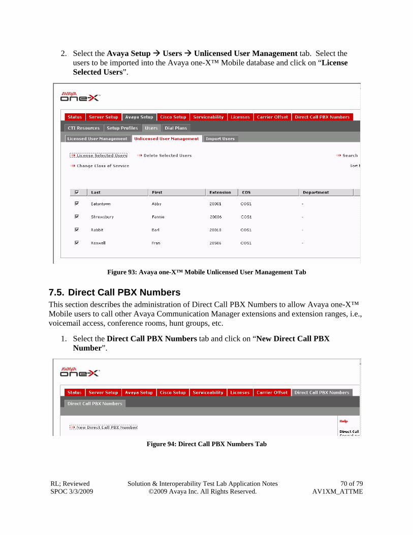
2. Select the Avaya Setup Users Unlicensed User Management tab. Select the users to be imported into the Avaya one-X™ Mobile database and click on “License Selected Users”.
Figure 93: Avaya one-X™ Mobile Unlicensed User Management Tab
7.5. Direct Call PBX Numbers This section describes the administration of Direct Call PBX Numbers to allow Avaya one-X™ Mobile users to call other Avaya Communication Manager extensions and extension ranges, i.e., voicemail access, conference rooms, hunt groups, etc.
1. Select the Direct Call PBX Numbers tab and click on “New Direct Call PBX Number”.
2. In the New Direct Call PBX Number page, provision the following and click on “Save”: • Switch HostName – Set to the IP address of the Avaya Communication Manager
server. • Leading String - Enter enough leading digits to match an Avaya Communication
Manager extension or extension range. • Digit Count – Enter the number of digits in the Avaya Communication Manager
extension or extension range.
Figure 95: Avaya one-X™ Mobile New Direct Call PBX N umber Page
8. Interoperability Compliance Testing The interoperability compliance testing focused on verifying inbound and outbound call flows, as well as Avaya one-X™ Mobile UC client features such as inbound call management, Visual Voicemail, corporate directory (e.g., LDAP) searches, and click-to-call.
8.1. General Test Approach A simulated enterprise site consisting of an Avaya one-X™ Mobile solution with ISDN-PRI trunking as described in Section 1.1 was configured and used during testing. The main test objectives were to verify the following features and functionality:
• Inbound business calls, whether from an external PSTN caller or internal (office) caller, to an Avaya one-X™ Mobile user ring all of the user’s selected receive (“Send Calls”) destinations (e.g., office phone, mobile phone, home phone, other landline phones, etc.). Upon answer at any one of the receive destinations, the called user is connected to the caller, and ringing stops on the other receive destinations. • Using the Avaya one-X™ Mobile UC client application (running on the mobile phone), an Avaya one-X™ Mobile user establishes outbound business calls from the mobile phone to other internal (office) extensions and external PSTN numbers. • Using the Avaya one-X™ Mobile UC client application, an Avaya one-X™ Mobile user establishes outbound business calls from any phone other than the mobile phone (e.g., home phone, other landline phones, etc.) to other internal (office) extensions or external PSTN numbers. • An Avaya one-X™ Mobile user moves an active business call from the office phone to the mobile phone, and vice versa. • Inbound business calls that are not answered at any of an Avaya one-X™ Mobile user’s selected receive destinations are sent to the user’s corporate voice mailbox. • Using the Avaya one-X™ Mobile UC client application, an Avaya one-X™ Mobile user elects to allow inbound calls only from selected parties (“VIPs”) and block all others (“Non-VIPs”). Subsequent inbound calls from VIPs ring all of the user’s selected receive destinations, and inbound calls from Non-VIPs are sent directly to the user’s corporate voice mailbox. • Using the Avaya one-X™ Mobile UC client application, an Avaya one-X™ Mobile user searches the corporate directory (LDAP) for other users’ contact information. • An Avaya one-X™ Mobile user’s new and saved voice messages as shown in the Avaya one-X™ Mobile UC client application are consistent with the user’s corporate voice mailbox (Avaya Modular Messaging), and the user is able to view, listen to, save, and delete the messages in any order using the Avaya one-X™ Mobile UC client application. Note: The Avaya one-X™ Mobile UC client application does not include zero-length voice messages in the new and saved voice messages lists. • An Avaya one-X™ Mobile user “clicks-to-call” other internal (office) extensions and external PSTN numbers from the Avaya one-X™ Mobile UC client application call log, corporate directory search results, and Visual Voicemail inboxes. • When an Avaya one-X™ Mobile user executes a call from within the Avaya one-X™ Mobile UC client application, the digits entered by the user are inspected for a match
against a list of emergency access numbers. If a match is found by the one-X™ Mobile UC client software, the call is redirected to the mobile phone’s native dialer. The emergency call is then made from the mobile phone’s native dialer to the AT&T wireless network, and ultimately delivered to a Public Safety Answering Point (PSAP). Since the emergency call is originated from the mobile phone's native dialer, the PSAP receives the user's mobile phone number, rather than the user's office/business number, as the originator of the call.
8.2. Test Results The test objectives of Section 8.1 were verified. Note that this configuration requires Update 16732 for Avaya Communication Manager release 5.1.1. Subsequent releases of Avaya Communication Manager are expected to incorporate this update within the primary release.
9. Verification Steps 9.1. Verification Tests The following steps may be used to verify the configuration:
1. In the Avaya Communication Manager SAT interface, enter the status aesvcs interface command. Verify that there is an entry where Local Node is the Node Name entered in the ip-services from in Section 3.6 Step 3, and for that entry, verify that the interface is Enabled and the Status is “listening”.
status aesvcs interface AE SERVICES INTERFACE STATUS Local Node Enabled? Number of Status Connections clan-01a08 yes 1 listening
Figure 96: Status AESVCS Interface
2. Enter the status aesvcs link command. Verify that there is an entry where: • AE Services server is the hostname of the Avaya AE Services server. • Srvr is the Server ID of the Avaya AE Services server entered in the ip-services form in Section 3.6 Step 4. • Link is the number of the CTI link administered in Section 3.6 Step 1. For that entry, verify Remote IP is the IP address of the Avaya AE Services server and Local Node is the Node Name entered in the ip-services from in Section 3.6 Step 3.
status aesvcs link AE SERVICES LINK STATUS Srvr/ AE Services Remote IP Remote Local Node Msgs Msgs Link Server Port Sent Rcvd 01/01 aes1 12.160.179.115 33045 clan-01a08 207 193
3. Enter the status aesvcs cti-link command. Verify that there is an entry where CTI Link is the number of the CTI link administered in Section 3.6 Step 1 and AE Services Server is the hostname of the Avaya AE Services server. For that entry, verify that Mnt Busy is “no” and the Service State is “established”.
status aesvcs cti-link AE SERVICES CTI LINK STATUS CTI Version Mnt AE Services Service Msgs Msgs Link Busy Server State Sent Rcvd 1 4 no aes1 established 15 15
Figure 98: Status AESVCS CTI-Link
4. Enter the list monitored-station command. Verify that there are entries for each office extension of the Avaya one-X™ Mobile users, as well as entries for at least two of the CTI Port extensions administered in Section 7.3. Verify that for each of those entries, Association 1 CTI Link is the number of the CTI link administered in Section 3.6 Step 1.
list monitored-station Page 1 MONITORED STATION Station Association 1 Association 2 Association 3 Association 4 Ext CTI Link CRV CTI Link CRV CTI Link CRV CTI Link CRV ------- ------------- ------------- ------------- ------------- 20001 1 14 20002 1 26 20003 1 23 20004 1 22 29037 1 30 29038 1 16
Figure 99: List Monitored-Station
5. In the left pane of the Avaya AE Services CTI OAM Administration web interface, click on Status and Control Switch Conn Summary. In the Switch Connections Summary page, verify that the Conn State of the Switch Connection administered in Section 4.4 Steps 1 - 2 is “Talking”.
Figure 100: Switch Connections Summary Page
6. In the left pane, click on Status and Control Services Summary. In the Services
Summary page, select the TSAPI Service radio button and click on “Details”.
Figure 101: Services Summary Page
7. In the TSAPI Link Details page, verify that the Conn Status of the TSAPI Link
administered in Section 4.4 Steps 5 - 7 is “Talking”, and click on “User Status”.
8. In the CTI User Status page, verify that the JTAPI user administered in Section 4.2 Step
3 has an “Open” stream.
Figure 103: CTI User Status Page
9. Place inbound calls to an Avaya one-X™ Mobile user and verify that all of the user’s
selected receive destinations ring. Answer the calls, verify two-way talkpath, and verify that the calls remain stable for several minutes and disconnect properly.
10. Use the Avaya one-X™ Mobile UC client application to place outbound calls from an Avaya one-X™ Mobile user’s phones (mobile phone, home phone, other landline phones, etc.). Answer the calls, verify two-way talkpath, and verify that the calls remain stable for several minutes and disconnect properly.
11. Leave voice messages on an Avaya one-X™ Mobile user’s corporate voice mailbox and
verify that the user’s Avaya one-X™ Mobile UC client application correctly displays the number of new voice messages.
12. Use the Avaya one-X™ Mobile UC client application to view, listen to, save, and delete
voice messages, and verify that Avaya Modular Messaging is updated accordingly. Perform the same functions on Avaya Modular Messaging and verify that the Avaya one-X™ Mobile UC client application is updated accordingly.
9.2. Troubleshooting Tools The Avaya Communication Manager “list trace station”, “list trace tac”, “status station”, and/or “status trunk-group” commands are helpful diagnostic tools to verify correct operation and to troubleshoot problems. MST (Message Sequence Trace) diagnostic traces (performed by Avaya support) can be helpful in understanding the specific interoperability issues.
10. Support AT&T customers can get support for AT&T Mobile Extension by calling (888) 334-3787 or (800) 331-0500. Avaya customers may obtain documentation and support for Avaya products by visiting http://support.avaya.com. The “Connect with Avaya” section provides the worldwide support directory. In the United States, (866) GO-AVAYA (866-462-8292) provides access to overall sales and service support menus. Customers may also use specific numbers (provided on http://support.avaya.com) to directly access specific support and consultation services based upon their Avaya support agreements.
11. Conclusion These Application Notes described the steps for configuring Avaya one-X™ Mobile and Avaya Communication Manager with AT&T Mobile Extension and ISDN-PRI trunks. Avaya one-X™ Mobile is an enterprise mobility solution that allows users roaming or otherwise located away from the office to access enterprise telephony and unified communications services. The AT&T Mobile Extension offer is an integrated solution that provides all the necessary components to enable wireless-PBX integration at the enterprise, including a cost control capability for enterprise wireless usage. The AT&T Mobile Extension offer is based on the combination of enterprise communications products, AT&T wireless handsets, and AT&T wireless enterprise rate plans. The sample configuration shown in these Application Notes is representative of a basic enterprise customer configuration and is intended to provide configuration guidance to
supplement other Avaya product documentation. It is based upon formal interoperability compliance testing as part of the Avaya DevConnect Service Provider program.
12. References The Avaya product documentation is available at http://support.avaya.com unless otherwise noted. [1] Avaya one-X™ Mobile Installation Guide, Issue 2, December 2008, Document Number 18-
602135 [2] Avaya one-X™ Mobile Integration, Administration, and Maintenance Guide, Issue 2,
December 2008, Document Number 18-602153 [3] Administrator Guide for Avaya Communication Manager, Issue 4, January 2008, Document
Number 03-300509 [4] Feature Description and Implementation for Avaya Communication Manager, Issue 6,
January 2008, Document Number 555-245-205 [5] Avaya MultiVantage Application Enablement Services Administration and Maintenance
Guide Release 4.2, Issue 10, May 2008, Document Number 02-300357 [6] Avaya one-X™ Mobile Web User Guide, Issue 2, December 2008, Document Number 18-
602150 [7] Avaya one-X™ Mobile User Guide for iPhone, Issue 2, December 2008, Document Number
18-602788 [8] Avaya one-X™ Mobile User Guide for RIM BlackBerry, Issue 2, December 2008, Document
Number 18-602148 [9] Avaya one-X™ Mobile User Guide for Windows Mobile, Issue 2, December 2008, Document