Configuring SIP Trunks between Avaya Aura™ Session Manager Release 6.0, Avaya Aura™ Communication Manager Evolution Server Release 6.0, and Avaya IP Office Release 6.0 – Issue 1.0
Abstract
These Application Notes present a sample configuration for a network that uses Avaya Aura™ Session Manager Release 6.0 to connect Avaya Aura™ Communication Manager Evolution Server Release 6.0 and Avaya IP Office Release 6.0 using SIP trunks. Session Initiated Protocol (SIP) is a standard based communication protocol capable of supporting voice, video, instant messaging and other multi-media communication. These Application Notes will outline a solution for using SIP as a trunk protocol between Avaya Aura™ Session Manager, Avaya Aura™ Communication Manager and Avaya IP Office.
5 Configure Avaya Aura™ Communication Manager Evolution Server ........................ 19 5.1 Verify Communication Manager License ...................................................................... 19 5.2 Configure System Parameters Features .......................................................................... 20 5.3 Configure IP Node Names ............................................................................................. 21 5.4 Configure IP Interface for C-LAN ................................................................................. 21 5.5 Configure IP Codec Sets and Network Regions ............................................................ 22 5.6 Configure SIP Signaling Group and Trunk Group ......................................................... 22
5.6.1 SIP Signaling Group ............................................................................................... 22 5.6.2 SIP Trunk Group ..................................................................................................... 23
5.7 Configure Route Pattern ................................................................................................. 24 5.8 Configure Private Numbering ........................................................................................ 25 5.9 Administer Dial Plan and AAR Analysis ....................................................................... 25 5.10 Save Translation ......................................................................................................... 26
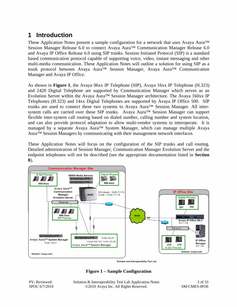
1 Introduction These Application Notes present a sample configuration for a network that uses Avaya Aura™ Session Manager Release 6.0 to connect Avaya Aura™ Communication Manager Release 6.0 and Avaya IP Office Release 6.0 using SIP trunks. Session Initiated Protocol (SIP) is a standard based communication protocol capable of supporting voice, video, instant messaging and other multi-media communication. These Application Notes will outline a solution for using SIP as a trunk protocol between Avaya Aura™ Session Manager, Avaya Aura™ Communication Manager and Avaya IP Office. As shown in Figure 1, the Avaya 96xx IP Telephone (SIP), Avaya 16xx IP Telephone (H.323) and 2420 Digital Telephone are supported by Communication Manager which serves as an Evolution Server within the Avaya Aura™ Session Manager architecture. The Avaya 160xx IP Telephones (H.323) and 14xx Digital Telephones are supported by Avaya IP Office 500. SIP trunks are used to connect these two systems to Avaya Aura™ Session Manager. All inter-system calls are carried over these SIP trunks. Avaya Aura™ Session Manager can support flexible inter-system call routing based on dialed number, calling number and system location, and can also provide protocol adaptation to allow multi-vendor systems to interoperate. It is managed by a separate Avaya Aura™ System Manager, which can manage multiple Avaya Aura™ Session Managers by communicating with their management network interfaces. These Application Notes will focus on the configuration of the SIP trunks and call routing. Detailed administration of Session Manager, Communication Manager Evolution Server and the endpoint telephones will not be described (see the appropriate documentation listed in Section 8).
2 Equipment and Software Validated The following equipment and software were used for the sample configuration provided:
Hardware Component Software Version
Avaya S8800 Server Avaya Aura™ Session Manager Release 6.0 Avaya Aura™ System Manager, Release 6.0
Avaya S8800 Servers with G650 Media Gateway Avaya Aura™ Communication Manager Release 6.0 Avaya 9630 IP Telephone (H.323) ha1608b1011.bin Avaya 9630 IP Telephone (SIP) 2.6.7.2a Avaya 2420 Digital Telephone NA Avaya IP Office Server (500 V2) Release 6.0 Avaya 14xx Digital Telephones NA Avaya 16xx IP Telephone (H.323) ha1608ual_2110.bin
3 Configure Avaya IP Office This section provides the procedures for configuring Avaya IP Office. The procedures include the following areas: Verify IP Office license Obtain LAN IP address Configure Network Topology Administer SIP Registrar Administer Codec Preference Administer SIP Trunk Administer Short Code Configure Incoming Call Route Configure Users SIP Names
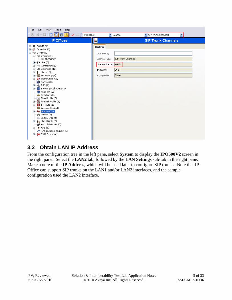
3.1 Verify IP Office License From a PC running the Avaya IP Office Manager application, select Start > Programs > IP Office > Manager to launch the Manager application. Select the proper IP Office system, and log in with the appropriate credentials. The Avaya IP Office Manager screen is displayed. From the configuration tree in the left pane, select License > SIP Trunk Channels to display the SIP Trunk Channels screen in the right pane. Verify that the License Status is “Valid”. If there is insufficient capacity or a required feature is not enabled, contact an authorized Avaya sales representative to make the appropriate changes.
3.2 Obtain LAN IP Address From the configuration tree in the left pane, select System to display the IPO500V2 screen in the right pane. Select the LAN2 tab, followed by the LAN Settings sub-tab in the right pane. Make a note of the IP Address, which will be used later to configure SIP trunks. Note that IP Office can support SIP trunks on the LAN1 and/or LAN2 interfaces, and the sample configuration used the LAN2 interface.
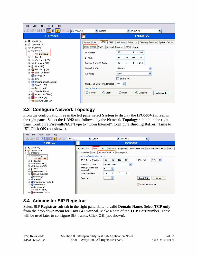
3.3 Configure Network Topology From the configuration tree in the left pane, select System to display the IPO500V2 screen in the right pane. Select the LAN2 tab, followed by the Network Topology sub-tab in the right pane. Configure Firewall/NAT Type to “Open Internet”. Configure Binding Refresh Time to “5”. Click OK (not shown).
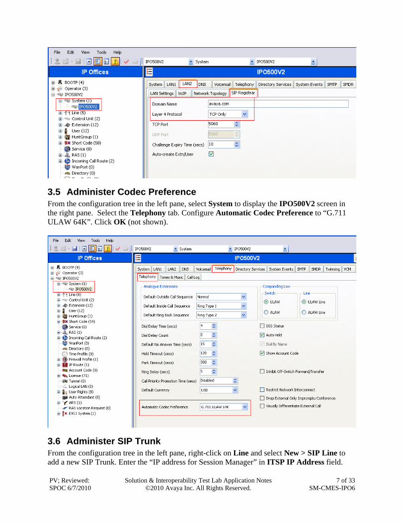
3.4 Administer SIP Registrar Select SIP Registrar sub-tab in the right pane. Enter a valid Domain Name. Select TCP only from the drop down menu for Layer 4 Protocol. Make a note of the TCP Port number. These will be used later to configure SIP trunks. Click OK (not shown).
3.5 Administer Codec Preference From the configuration tree in the left pane, select System to display the IPO500V2 screen in the right pane. Select the Telephony tab. Configure Automatic Codec Preference to “G.711 ULAW 64K”. Click OK (not shown).
3.6 Administer SIP Trunk From the configuration tree in the left pane, right-click on Line and select New > SIP Line to add a new SIP Trunk. Enter the “IP address for Session Manager” in ITSP IP Address field.
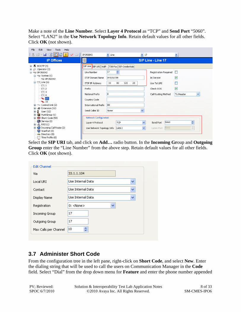
Make a note of the Line Number. Select Layer 4 Protocol as “TCP” and Send Port “5060”. Select “LAN2” in the Use Network Topology Info. Retain default values for all other fields. Click OK (not shown).
Select the SIP URI tab, and click on Add… radio button. In the Incoming Group and Outgoing Group enter the “Line Number” from the above step. Retain default values for all other fields. Click OK (not shown).
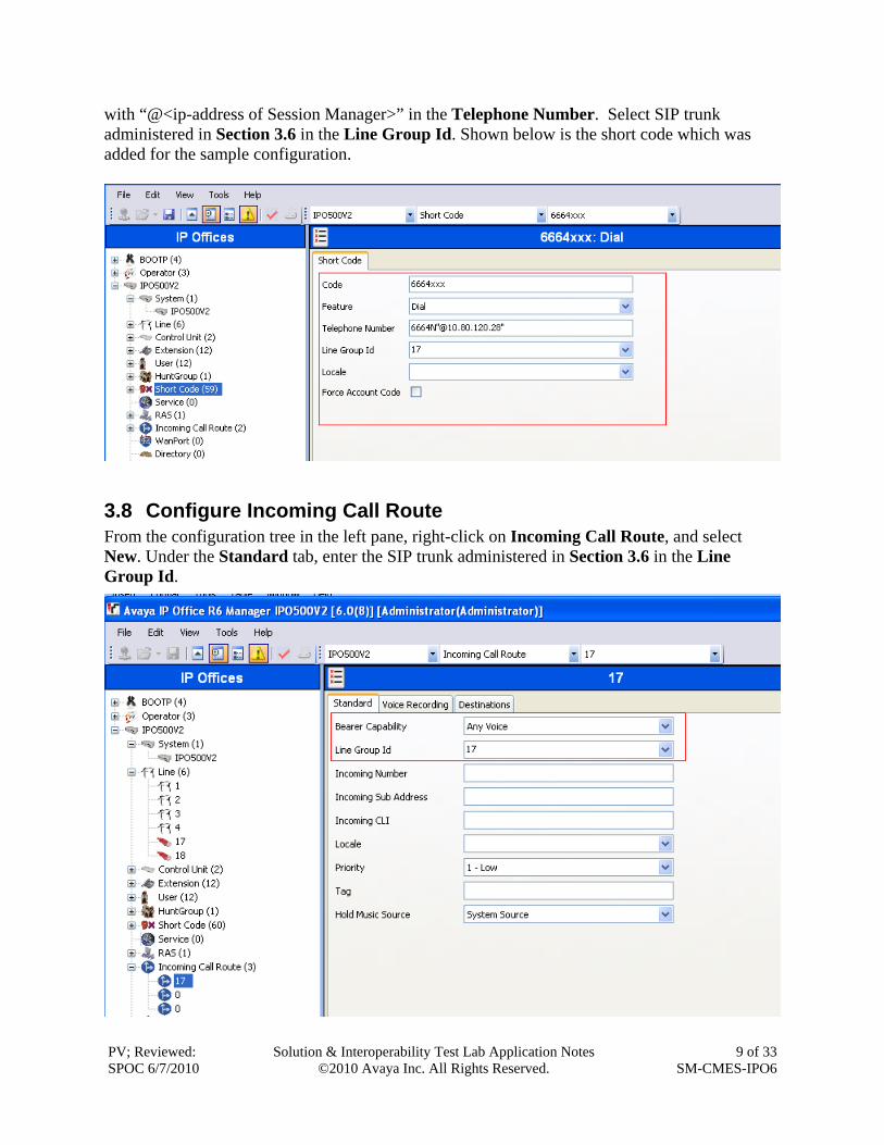
3.7 Administer Short Code From the configuration tree in the left pane, right-click on Short Code, and select New. Enter the dialing string that will be used to call the users on Communication Manager in the Code field. Select “Dial” from the drop down menu for Feature and enter the phone number appended
with “@<ip-address of Session Manager>” in the Telephone Number. Select SIP trunk administered in Section 3.6 in the Line Group Id. Shown below is the short code which was added for the sample configuration.
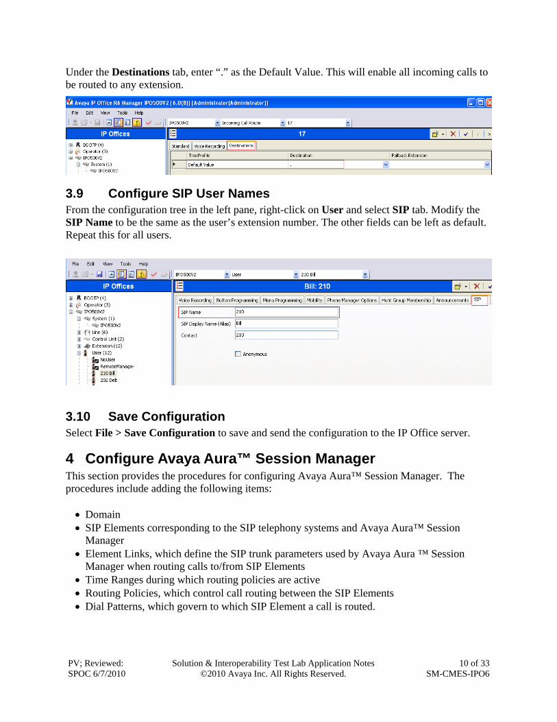
3.8 Configure Incoming Call Route From the configuration tree in the left pane, right-click on Incoming Call Route, and select New. Under the Standard tab, enter the SIP trunk administered in Section 3.6 in the Line Group Id.
Under the Destinations tab, enter “.” as the Default Value. This will enable all incoming calls to be routed to any extension.
3.9 Configure SIP User Names From the configuration tree in the left pane, right-click on User and select SIP tab. Modify the SIP Name to be the same as the user’s extension number. The other fields can be left as default. Repeat this for all users.
3.10 Save Configuration Select File > Save Configuration to save and send the configuration to the IP Office server.
4 Configure Avaya Aura™ Session Manager This section provides the procedures for configuring Avaya Aura™ Session Manager. The procedures include adding the following items: Domain SIP Elements corresponding to the SIP telephony systems and Avaya Aura™ Session
Manager Element Links, which define the SIP trunk parameters used by Avaya Aura ™ Session
Manager when routing calls to/from SIP Elements Time Ranges during which routing policies are active Routing Policies, which control call routing between the SIP Elements Dial Patterns, which govern to which SIP Element a call is routed.
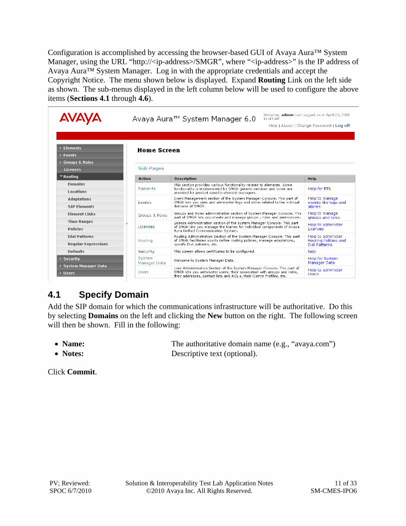
Configuration is accomplished by accessing the browser-based GUI of Avaya Aura™ System Manager, using the URL “http://<ip-address>/SMGR”, where “<ip-address>” is the IP address of Avaya Aura™ System Manager. Log in with the appropriate credentials and accept the Copyright Notice. The menu shown below is displayed. Expand Routing Link on the left side as shown. The sub-menus displayed in the left column below will be used to configure the above items (Sections 4.1 through 4.6).
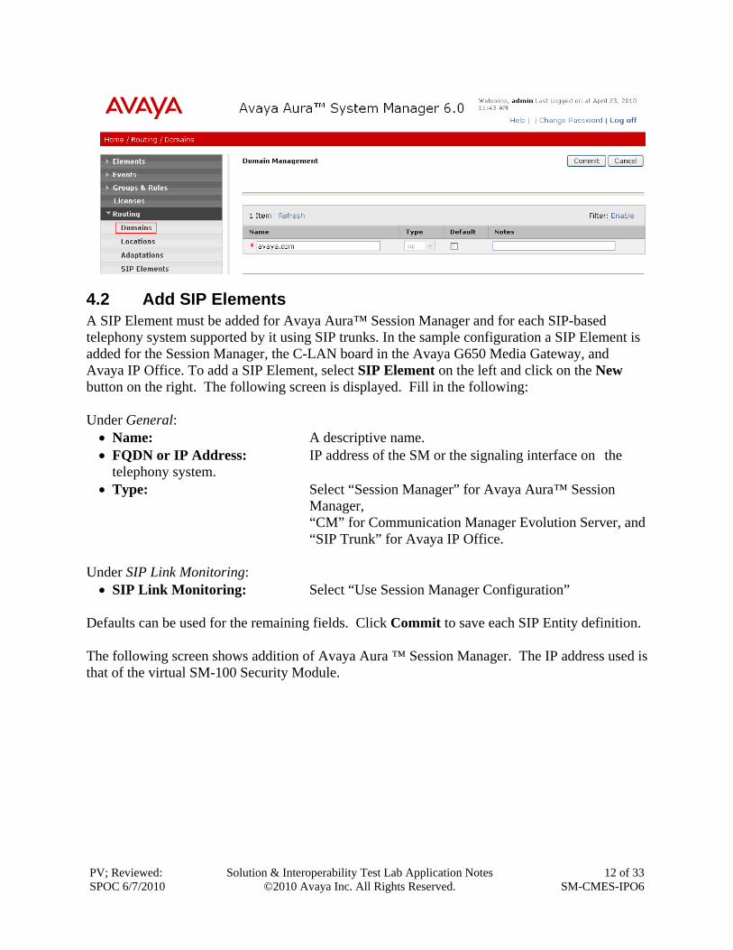
4.1 Specify Domain Add the SIP domain for which the communications infrastructure will be authoritative. Do this by selecting Domains on the left and clicking the New button on the right. The following screen will then be shown. Fill in the following: Name: The authoritative domain name (e.g., “avaya.com”) Notes: Descriptive text (optional).
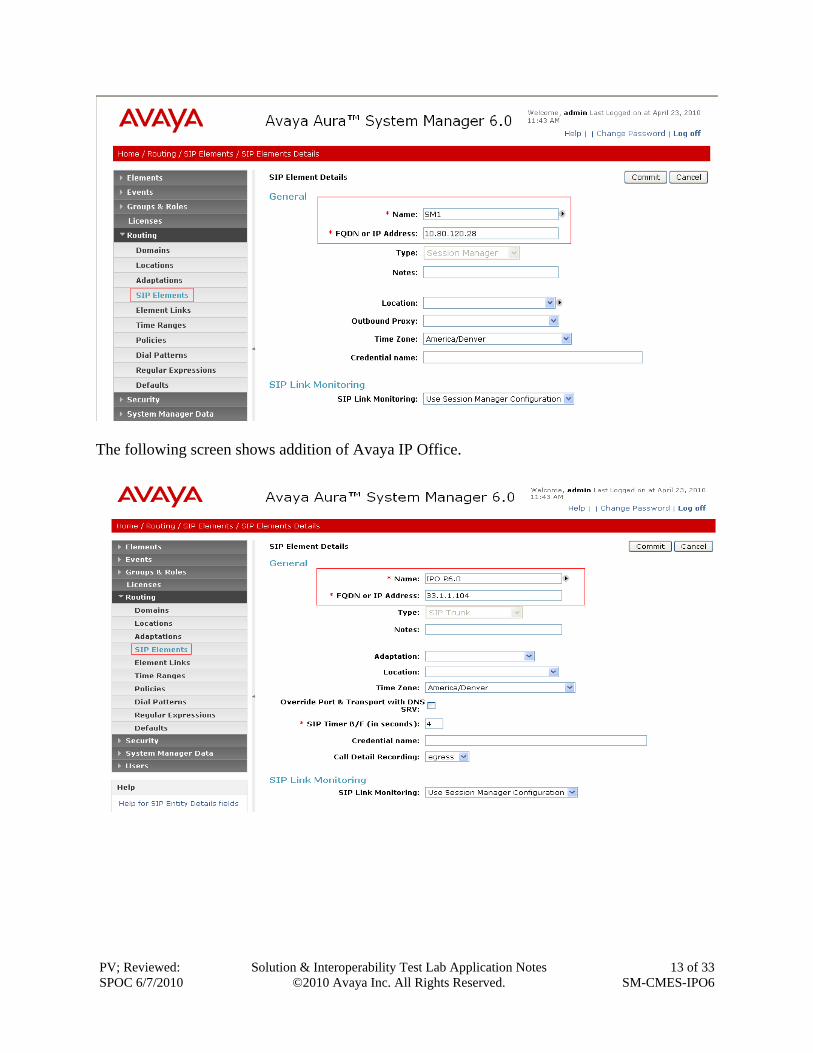
4.2 Add SIP Elements A SIP Element must be added for Avaya Aura™ Session Manager and for each SIP-based telephony system supported by it using SIP trunks. In the sample configuration a SIP Element is added for the Session Manager, the C-LAN board in the Avaya G650 Media Gateway, and Avaya IP Office. To add a SIP Element, select SIP Element on the left and click on the New button on the right. The following screen is displayed. Fill in the following: Under General: Name: A descriptive name. FQDN or IP Address: IP address of the SM or the signaling interface on the
telephony system. Type: Select “Session Manager” for Avaya Aura™ Session
Manager, “CM” for Communication Manager Evolution Server, and
“SIP Trunk” for Avaya IP Office. Under SIP Link Monitoring: SIP Link Monitoring: Select “Use Session Manager Configuration”
Defaults can be used for the remaining fields. Click Commit to save each SIP Entity definition. The following screen shows addition of Avaya Aura ™ Session Manager. The IP address used is that of the virtual SM-100 Security Module.
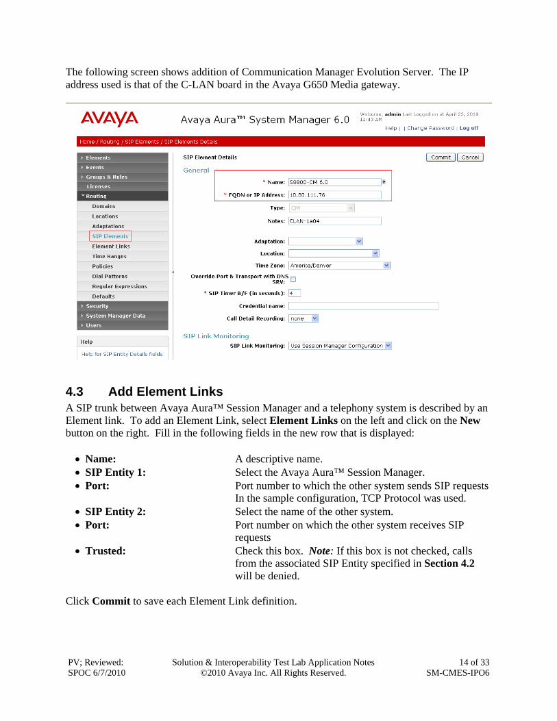
The following screen shows addition of Communication Manager Evolution Server. The IP address used is that of the C-LAN board in the Avaya G650 Media gateway.
4.3 Add Element Links A SIP trunk between Avaya Aura™ Session Manager and a telephony system is described by an Element link. To add an Element Link, select Element Links on the left and click on the New button on the right. Fill in the following fields in the new row that is displayed: Name: A descriptive name. SIP Entity 1: Select the Avaya Aura™ Session Manager. Port: Port number to which the other system sends SIP requests In the sample configuration, TCP Protocol was used. SIP Entity 2: Select the name of the other system. Port: Port number on which the other system receives SIP
requests Trusted: Check this box. Note: If this box is not checked, calls
from the associated SIP Entity specified in Section 4.2 will be denied.
Click Commit to save each Element Link definition.
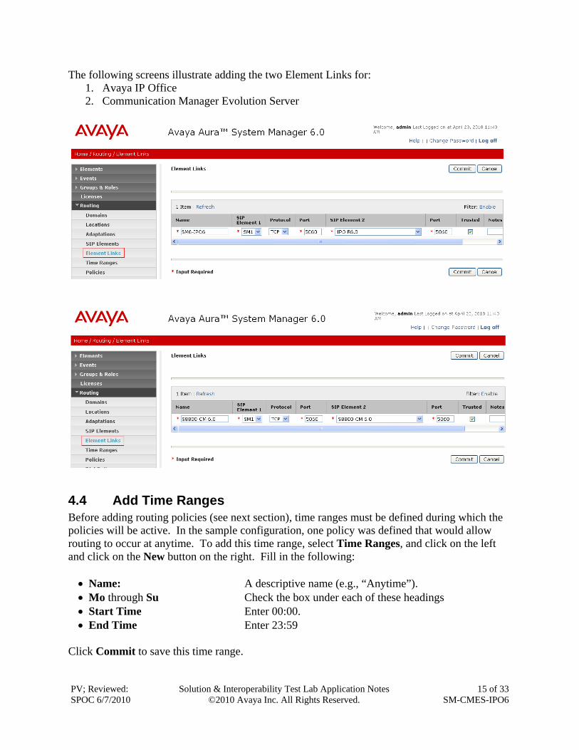
The following screens illustrate adding the two Element Links for: 1. Avaya IP Office 2. Communication Manager Evolution Server
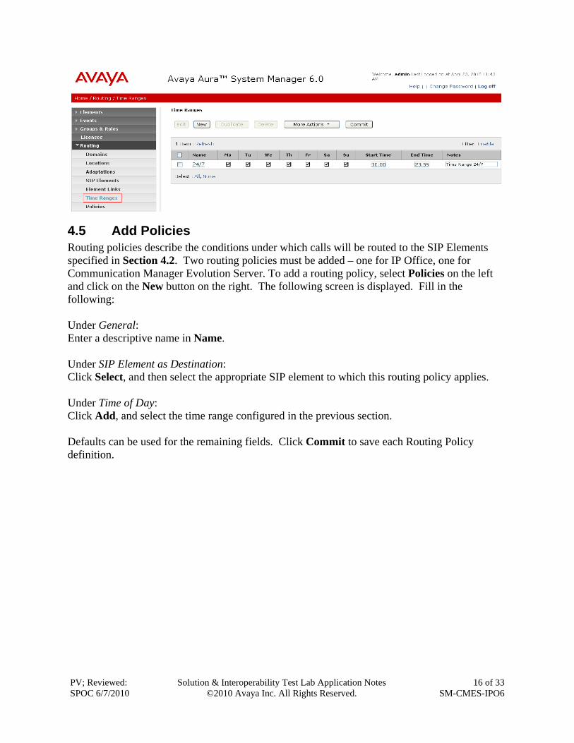
4.4 Add Time Ranges Before adding routing policies (see next section), time ranges must be defined during which the policies will be active. In the sample configuration, one policy was defined that would allow routing to occur at anytime. To add this time range, select Time Ranges, and click on the left and click on the New button on the right. Fill in the following: Name: A descriptive name (e.g., “Anytime”). Mo through Su Check the box under each of these headings Start Time Enter 00:00. End Time Enter 23:59
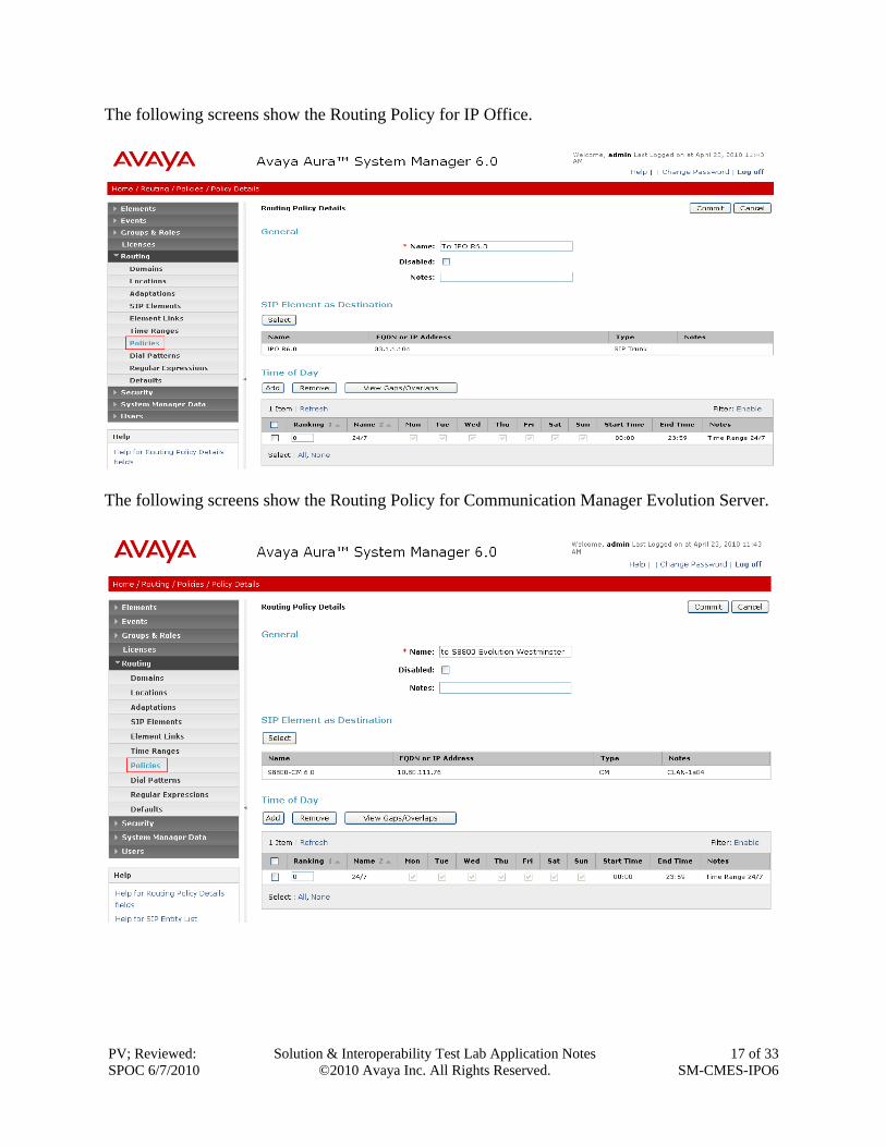
4.5 Add Policies Routing policies describe the conditions under which calls will be routed to the SIP Elements specified in Section 4.2. Two routing policies must be added – one for IP Office, one for Communication Manager Evolution Server. To add a routing policy, select Policies on the left and click on the New button on the right. The following screen is displayed. Fill in the following: Under General: Enter a descriptive name in Name. Under SIP Element as Destination: Click Select, and then select the appropriate SIP element to which this routing policy applies. Under Time of Day: Click Add, and select the time range configured in the previous section. Defaults can be used for the remaining fields. Click Commit to save each Routing Policy definition.
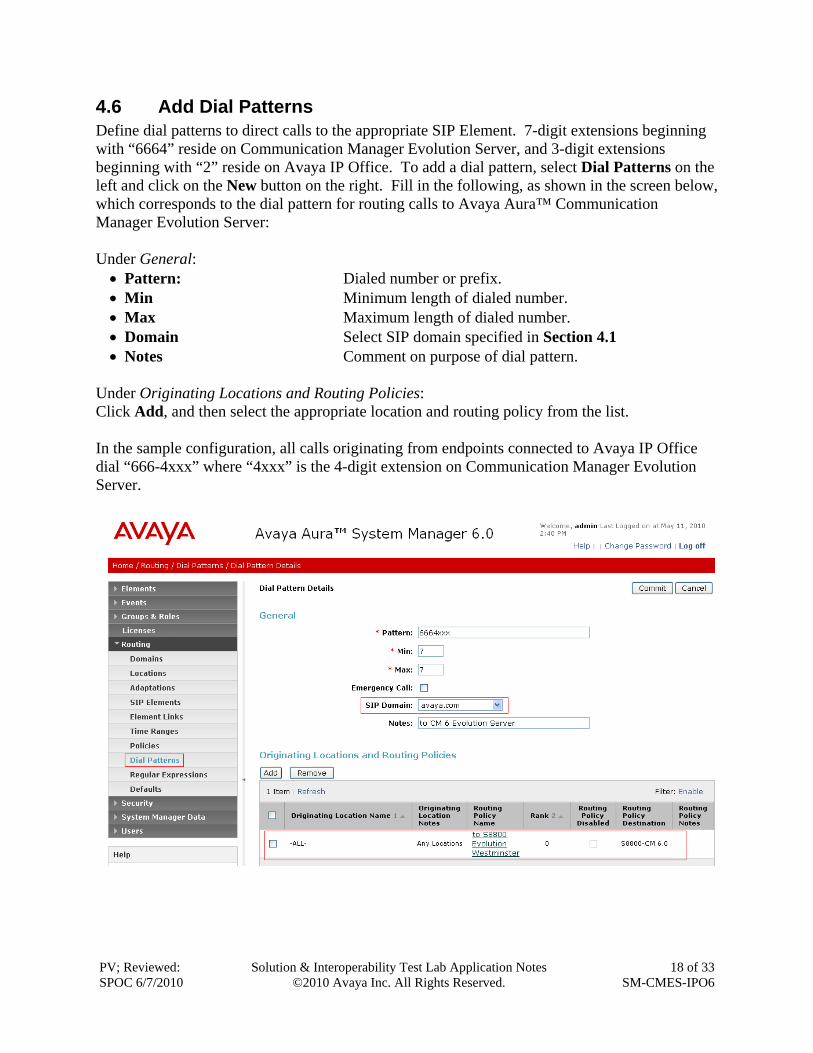
4.6 Add Dial Patterns Define dial patterns to direct calls to the appropriate SIP Element. 7-digit extensions beginning with “6664” reside on Communication Manager Evolution Server, and 3-digit extensions beginning with “2” reside on Avaya IP Office. To add a dial pattern, select Dial Patterns on the left and click on the New button on the right. Fill in the following, as shown in the screen below, which corresponds to the dial pattern for routing calls to Avaya Aura™ Communication Manager Evolution Server: Under General: Pattern: Dialed number or prefix. Min Minimum length of dialed number. Max Maximum length of dialed number. Domain Select SIP domain specified in Section 4.1 Notes Comment on purpose of dial pattern.
Under Originating Locations and Routing Policies: Click Add, and then select the appropriate location and routing policy from the list. In the sample configuration, all calls originating from endpoints connected to Avaya IP Office dial “666-4xxx” where “4xxx” is the 4-digit extension on Communication Manager Evolution Server.
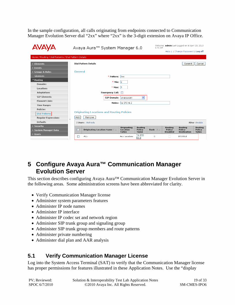
In the sample configuration, all calls originating from endpoints connected to Communication Manager Evolution Server dial “2xx” where “2xx” is the 3-digit extension on Avaya IP Office.
5 Configure Avaya Aura™ Communication Manager Evolution Server
This section describes configuring Avaya Aura™ Communication Manager Evolution Server in the following areas. Some administration screens have been abbreviated for clarity. Verify Communication Manager license Administer system parameters features Administer IP node names Administer IP interface Administer IP codec set and network region Administer SIP trunk group and signaling group Administer SIP trunk group members and route patterns Administer private numbering Administer dial plan and AAR analysis
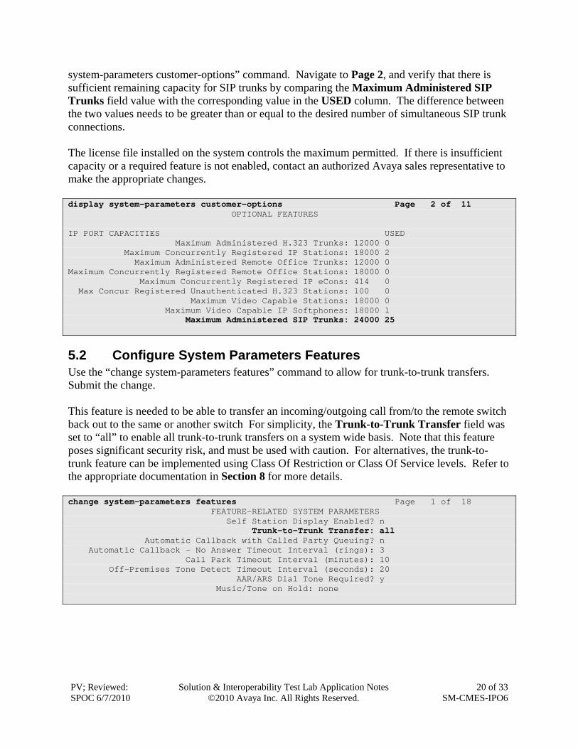
5.1 Verify Communication Manager License Log into the System Access Terminal (SAT) to verify that the Communication Manager license has proper permissions for features illustrated in these Application Notes. Use the “display
system-parameters customer-options” command. Navigate to Page 2, and verify that there is sufficient remaining capacity for SIP trunks by comparing the Maximum Administered SIP Trunks field value with the corresponding value in the USED column. The difference between the two values needs to be greater than or equal to the desired number of simultaneous SIP trunk connections. The license file installed on the system controls the maximum permitted. If there is insufficient capacity or a required feature is not enabled, contact an authorized Avaya sales representative to make the appropriate changes. display system-parameters customer-options Page 2 of 11 OPTIONAL FEATURES IP PORT CAPACITIES USED Maximum Administered H.323 Trunks: 12000 0 Maximum Concurrently Registered IP Stations: 18000 2 Maximum Administered Remote Office Trunks: 12000 0 Maximum Concurrently Registered Remote Office Stations: 18000 0 Maximum Concurrently Registered IP eCons: 414 0 Max Concur Registered Unauthenticated H.323 Stations: 100 0 Maximum Video Capable Stations: 18000 0 Maximum Video Capable IP Softphones: 18000 1 Maximum Administered SIP Trunks: 24000 25
5.2 Configure System Parameters Features Use the “change system-parameters features” command to allow for trunk-to-trunk transfers. Submit the change. This feature is needed to be able to transfer an incoming/outgoing call from/to the remote switch back out to the same or another switch For simplicity, the Trunk-to-Trunk Transfer field was set to “all” to enable all trunk-to-trunk transfers on a system wide basis. Note that this feature poses significant security risk, and must be used with caution. For alternatives, the trunk-to-trunk feature can be implemented using Class Of Restriction or Class Of Service levels. Refer to the appropriate documentation in Section 8 for more details. change system-parameters features Page 1 of 18 FEATURE-RELATED SYSTEM PARAMETERS Self Station Display Enabled? n Trunk-to-Trunk Transfer: all Automatic Callback with Called Party Queuing? n Automatic Callback - No Answer Timeout Interval (rings): 3 Call Park Timeout Interval (minutes): 10 Off-Premises Tone Detect Timeout Interval (seconds): 20 AAR/ARS Dial Tone Required? y Music/Tone on Hold: none
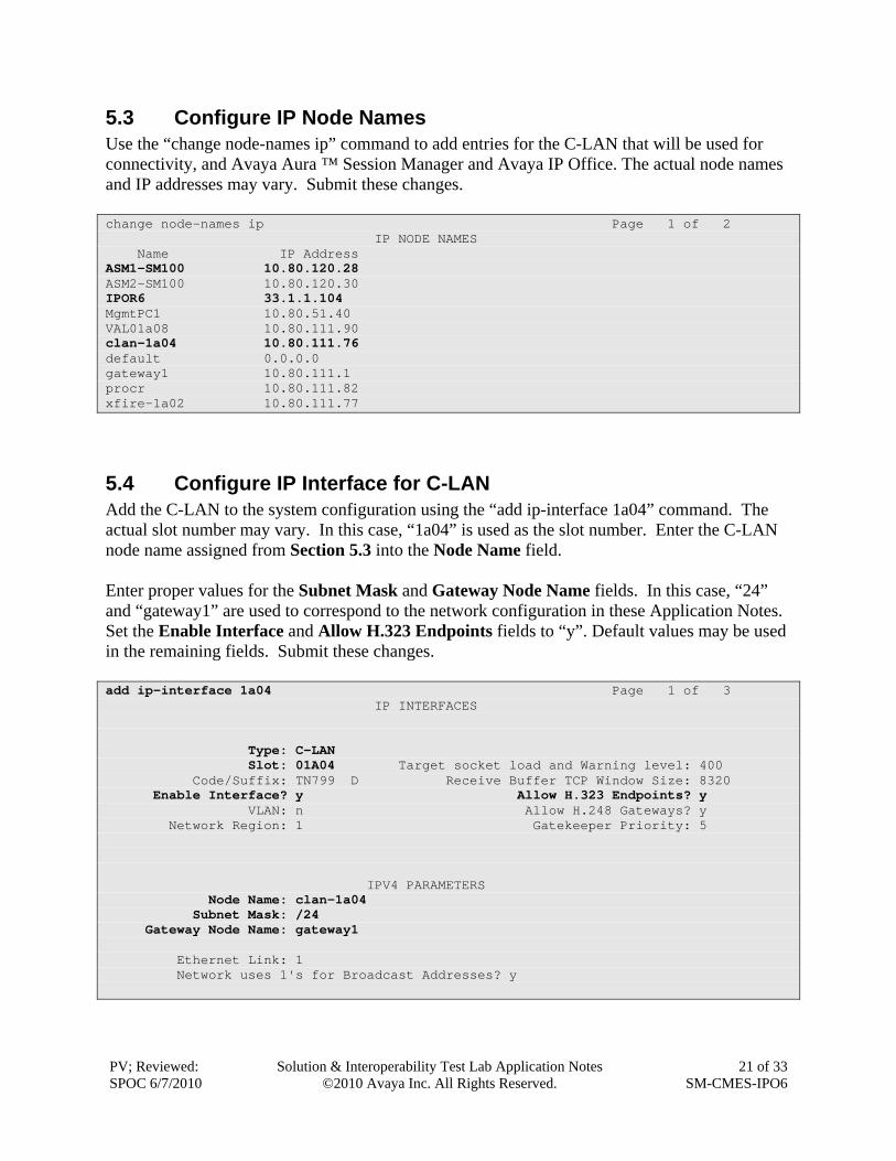
5.3 Configure IP Node Names Use the “change node-names ip” command to add entries for the C-LAN that will be used for connectivity, and Avaya Aura ™ Session Manager and Avaya IP Office. The actual node names and IP addresses may vary. Submit these changes. change node-names ip Page 1 of 2 IP NODE NAMES Name IP Address ASM1-SM100 10.80.120.28 ASM2-SM100 10.80.120.30 IPOR6 33.1.1.104 MgmtPC1 10.80.51.40 VAL01a08 10.80.111.90 clan-1a04 10.80.111.76 default 0.0.0.0 gateway1 10.80.111.1 procr 10.80.111.82 xfire-1a02 10.80.111.77
5.4 Configure IP Interface for C-LAN Add the C-LAN to the system configuration using the “add ip-interface 1a04” command. The actual slot number may vary. In this case, “1a04” is used as the slot number. Enter the C-LAN node name assigned from Section 5.3 into the Node Name field. Enter proper values for the Subnet Mask and Gateway Node Name fields. In this case, “24” and “gateway1” are used to correspond to the network configuration in these Application Notes. Set the Enable Interface and Allow H.323 Endpoints fields to “y”. Default values may be used in the remaining fields. Submit these changes. add ip-interface 1a04 Page 1 of 3 IP INTERFACES Type: C-LAN Slot: 01A04 Target socket load and Warning level: 400 Code/Suffix: TN799 D Receive Buffer TCP Window Size: 8320 Enable Interface? y Allow H.323 Endpoints? y VLAN: n Allow H.248 Gateways? y Network Region: 1 Gatekeeper Priority: 5 IPV4 PARAMETERS Node Name: clan-1a04 Subnet Mask: /24 Gateway Node Name: gateway1 Ethernet Link: 1 Network uses 1's for Broadcast Addresses? y
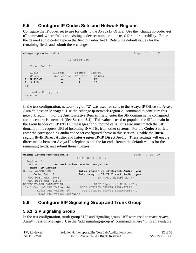
5.5 Configure IP Codec Sets and Network Regions Configure the IP codec set to use for calls to the Avaya IP Office. Use the “change ip-codec-set n” command, where “n” is an existing codec set number to be used for interoperability. Enter the desired audio codec type in the Audio Codec field. Retain the default values for the remaining fields and submit these changes. change ip-codec-set 2 Page 1 of 2 IP Codec Set Codec Set: 2 Audio Silence Frames Packet Codec Suppression Per Pkt Size(ms) 1: G.711MU n 2 20 2: G.729 n 2 20 3: Media Encryption 1: none
In the test configuration, network region “2” was used for calls to the Avaya IP Office via Avaya Aura ™ Session Manager. Use the “change ip-network-region 2” command to configure this network region. For the Authoritative Domain field, enter the SIP domain name configured for this enterprise network (See Section 3.4). This value is used to populate the SIP domain in the From header of SIP INVITE messages for outbound calls. It is also must match the SIP domain in the request URI of incoming INVITEs from other systems. For the Codec Set field, enter the corresponding audio codec set configured above in this section. Enable the Intra-region IP-IP Direct Audio, and Inter-region IP-IP Direct Audio. These settings will enable direct media between Avaya IP telephones and the far end. Retain the default values for the remaining fields, and submit these changes. change ip-network-region 2 Page 1 of 19 IP NETWORK REGION Region: 2 Location: 1 Authoritative Domain: avaya.com Name: IP Phones MEDIA PARAMETERS Intra-region IP-IP Direct Audio: yes Codec Set: 2 Inter-region IP-IP Direct Audio: yes UDP Port Min: 2048 IP Audio Hairpinning? n UDP Port Max: 16585 DIFFSERV/TOS PARAMETERS RTCP Reporting Enabled? y Call Control PHB Value: 46 RTCP MONITOR SERVER PARAMETERS Audio PHB Value: 46 Use Default Server Parameters? y Video PHB Value: 26change
5.6 Configure SIP Signaling Group and Trunk Group
5.6.1 SIP Signaling Group In the test configuration, trunk group “10” and signaling group “10” were used to reach Avaya Aura™ Session Manager. Use the “add signaling-group n” command, where “n” is an available
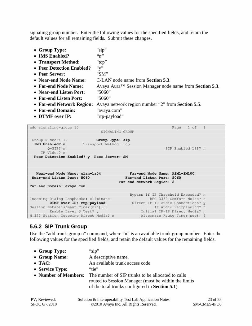
signaling group number. Enter the following values for the specified fields, and retain the default values for all remaining fields. Submit these changes. Group Type: “sip” IMS Enabled? “n” Transport Method: “tcp” Peer Detection Enabled? “y” Peer Server: “SM” Near-end Node Name: C-LAN node name from Section 5.3. Far-end Node Name: Avaya Aura™ Session Manager node name from Section 5.3. Near-end Listen Port: “5060” Far-end Listen Port: “5060” Far-end Network Region: Avaya network region number “2” from Section 5.5. Far-end Domain: “avaya.com” DTMF over IP: “rtp-payload”
add signaling-group 10 Page 1 of 1 SIGNALING GROUP Group Number: 10 Group Type: sip IMS Enabled? n Transport Method: tcp Q-SIP? n SIP Enabled LSP? n IP Video? n Peer Detection Enabled? y Peer Server: SM Near-end Node Name: clan-1a04 Far-end Node Name: ASM1-SM100 Near-end Listen Port: 5060 Far-end Listen Port: 5060 Far-end Network Region: 2 Far-end Domain: avaya.com Bypass If IP Threshold Exceeded? n Incoming Dialog Loopbacks: eliminate RFC 3389 Comfort Noise? n DTMF over IP: rtp-payload Direct IP-IP Audio Connections? y Session Establishment Timer(min): 3 IP Audio Hairpinning? n Enable Layer 3 Test? y Initial IP-IP Direct Media? n H.323 Station Outgoing Direct Media? n Alternate Route Timer(sec): 6
5.6.2 SIP Trunk Group Use the “add trunk-group n” command, where “n” is an available trunk group number. Enter the following values for the specified fields, and retain the default values for the remaining fields. Group Type: “sip” Group Name: A descriptive name. TAC: An available trunk access code. Service Type: “tie” Number of Members: The number of SIP trunks to be allocated to calls routed to Session Manager (must be within the limits of the total trunks configured in Section 5.1).
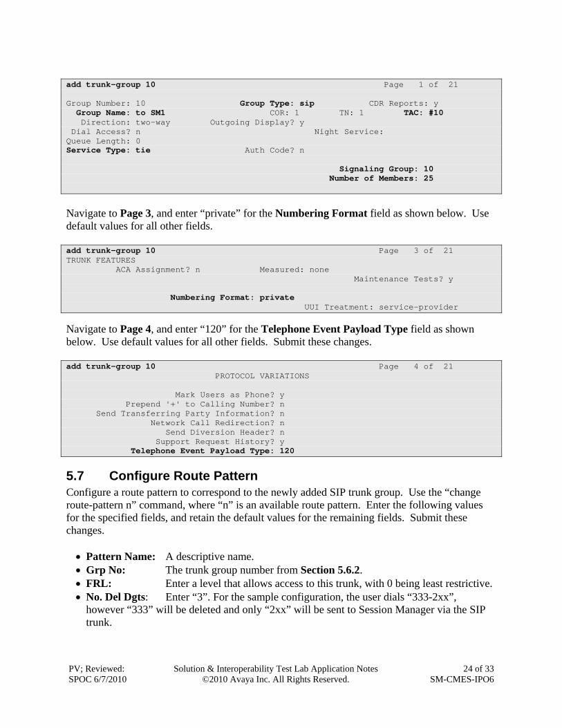
add trunk-group 10 Page 1 of 21 Group Number: 10 Group Type: sip CDR Reports: y Group Name: to SM1 COR: 1 TN: 1 TAC: #10 Direction: two-way Outgoing Display? y Dial Access? n Night Service: Queue Length: 0 Service Type: tie Auth Code? n Signaling Group: 10 Number of Members: 25
Navigate to Page 3, and enter “private” for the Numbering Format field as shown below. Use default values for all other fields. add trunk-group 10 Page 3 of 21 TRUNK FEATURES ACA Assignment? n Measured: none Maintenance Tests? y Numbering Format: private UUI Treatment: service-provider
Navigate to Page 4, and enter “120” for the Telephone Event Payload Type field as shown below. Use default values for all other fields. Submit these changes. add trunk-group 10 Page 4 of 21 PROTOCOL VARIATIONS Mark Users as Phone? y Prepend '+' to Calling Number? n Send Transferring Party Information? n Network Call Redirection? n Send Diversion Header? n Support Request History? y Telephone Event Payload Type: 120
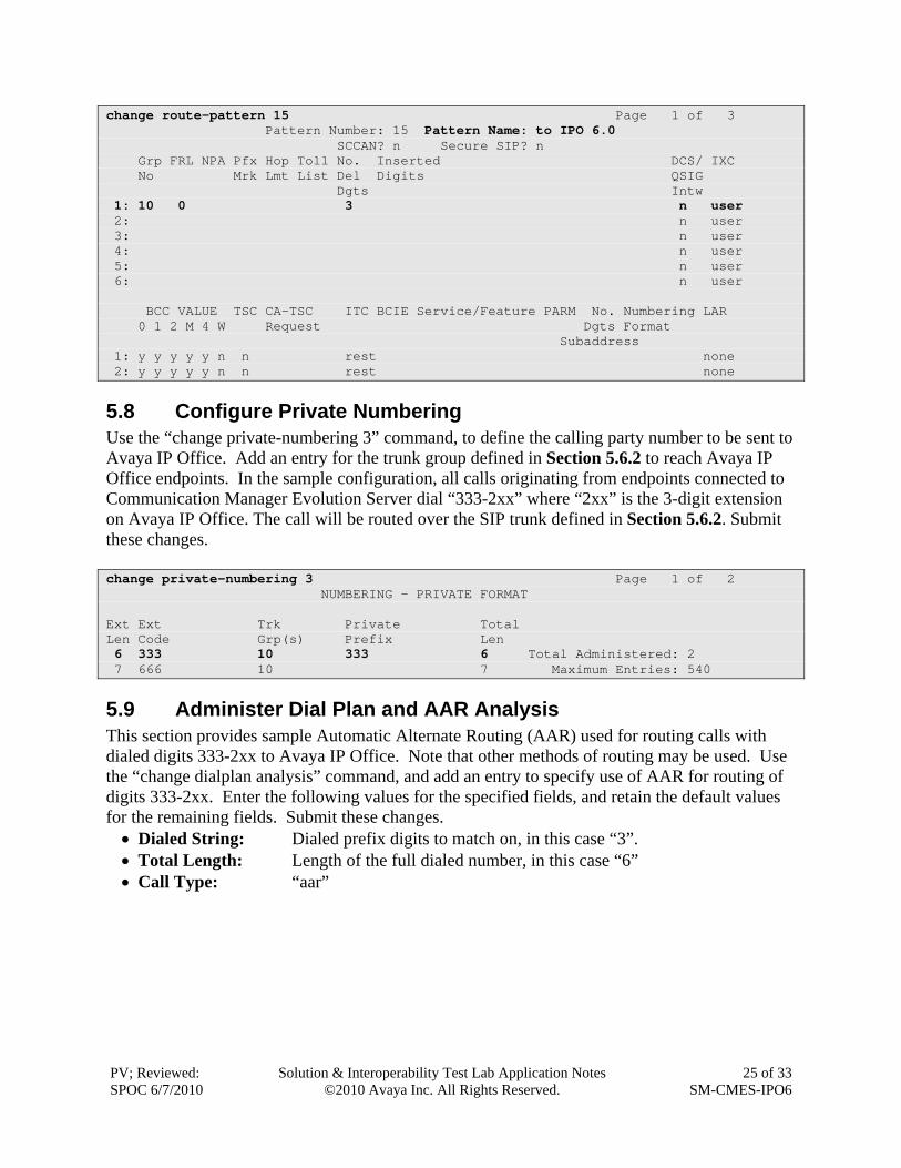
5.7 Configure Route Pattern Configure a route pattern to correspond to the newly added SIP trunk group. Use the “change route-pattern n” command, where “n” is an available route pattern. Enter the following values for the specified fields, and retain the default values for the remaining fields. Submit these changes. Pattern Name: A descriptive name. Grp No: The trunk group number from Section 5.6.2. FRL: Enter a level that allows access to this trunk, with 0 being least restrictive. No. Del Dgts: Enter “3”. For the sample configuration, the user dials “333-2xx”,
however “333” will be deleted and only “2xx” will be sent to Session Manager via the SIP trunk.
change route-pattern 15 Page 1 of 3 Pattern Number: 15 Pattern Name: to IPO 6.0 SCCAN? n Secure SIP? n Grp FRL NPA Pfx Hop Toll No. Inserted DCS/ IXC No Mrk Lmt List Del Digits QSIG Dgts Intw 1: 10 0 3 n user 2: n user 3: n user 4: n user 5: n user 6: n user BCC VALUE TSC CA-TSC ITC BCIE Service/Feature PARM No. Numbering LAR 0 1 2 M 4 W Request Dgts Format Subaddress 1: y y y y y n n rest none 2: y y y y y n n rest none
5.8 Configure Private Numbering Use the “change private-numbering 3” command, to define the calling party number to be sent to Avaya IP Office. Add an entry for the trunk group defined in Section 5.6.2 to reach Avaya IP Office endpoints. In the sample configuration, all calls originating from endpoints connected to Communication Manager Evolution Server dial “333-2xx” where “2xx” is the 3-digit extension on Avaya IP Office. The call will be routed over the SIP trunk defined in Section 5.6.2. Submit these changes. change private-numbering 3 Page 1 of 2 NUMBERING - PRIVATE FORMAT Ext Ext Trk Private Total Len Code Grp(s) Prefix Len 6 333 10 333 6 Total Administered: 2 7 666 10 7 Maximum Entries: 540
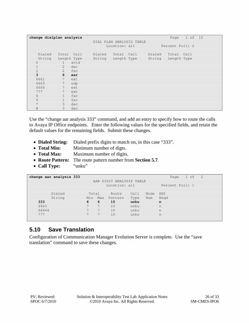
5.9 Administer Dial Plan and AAR Analysis This section provides sample Automatic Alternate Routing (AAR) used for routing calls with dialed digits 333-2xx to Avaya IP Office. Note that other methods of routing may be used. Use the “change dialplan analysis” command, and add an entry to specify use of AAR for routing of digits 333-2xx. Enter the following values for the specified fields, and retain the default values for the remaining fields. Submit these changes. Dialed String: Dialed prefix digits to match on, in this case “3”. Total Length: Length of the full dialed number, in this case “6” Call Type: “aar”
change dialplan analysis Page 1 of 12 DIAL PLAN ANALYSIS TABLE Location: all Percent Full: 2 Dialed Total Call Dialed Total Call Dialed Total Call String Length Type String Length Type String Length Type 0 1 attd 1 2 dac 2 2 fac 3 6 aar 6661 7 ext 6663 7 udp 6664 7 ext 777 7 ext 8 1 fac 9 1 fac * 3 dac # 3 dac
Use the “change aar analysis 333” command, and add an entry to specify how to route the calls to Avaya IP Office endpoints. Enter the following values for the specified fields, and retain the default values for the remaining fields. Submit these changes. Dialed String: Dialed prefix digits to match on, in this case “333”. Total Min: Minimum number of digts. Total Max: Maximum number of digits. Route Pattern: The route pattern number from Section 5.7. Call Type: “unku”
change aar analysis 333 Page 1 of 2 AAR DIGIT ANALYSIS TABLE Location: all Percent Full: 1 Dialed Total Route Call Node ANI String Min Max Pattern Type Num Reqd 333 6 6 15 unku n 6663 7 7 10 unku n 66644 7 7 10 unku n 777 7 7 10 unku n
5.10 Save Translation Configuration of Communication Manager Evolution Server is complete. Use the “save translation” command to save these changes.
6 Verification Steps This section provides the tests that can be performed on Avaya IP Office, Communication Manager and Session Manager to verify proper configuration of these systems.
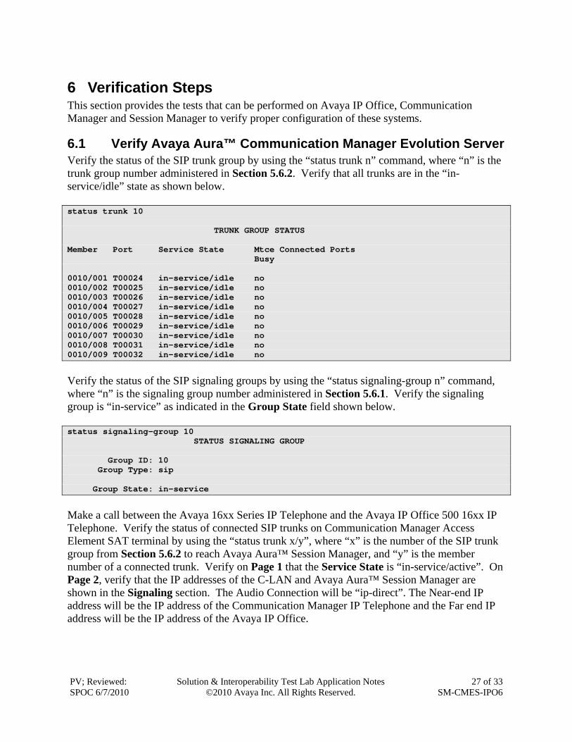
6.1 Verify Avaya Aura™ Communication Manager Evolution Server Verify the status of the SIP trunk group by using the “status trunk n” command, where “n” is the trunk group number administered in Section 5.6.2. Verify that all trunks are in the “in-service/idle” state as shown below. status trunk 10 TRUNK GROUP STATUS Member Port Service State Mtce Connected Ports Busy 0010/001 T00024 in-service/idle no 0010/002 T00025 in-service/idle no 0010/003 T00026 in-service/idle no 0010/004 T00027 in-service/idle no 0010/005 T00028 in-service/idle no 0010/006 T00029 in-service/idle no 0010/007 T00030 in-service/idle no 0010/008 T00031 in-service/idle no 0010/009 T00032 in-service/idle no
Verify the status of the SIP signaling groups by using the “status signaling-group n” command, where “n” is the signaling group number administered in Section 5.6.1. Verify the signaling group is “in-service” as indicated in the Group State field shown below. status signaling-group 10 STATUS SIGNALING GROUP Group ID: 10 Group Type: sip Group State: in-service
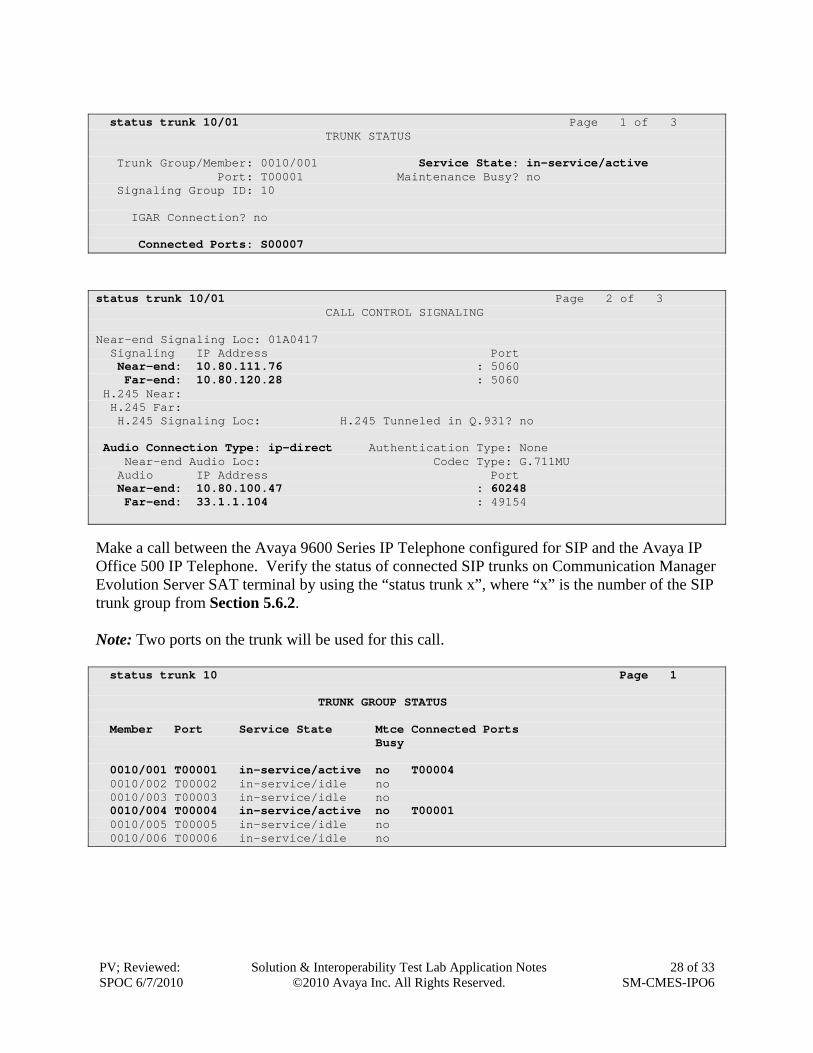
Make a call between the Avaya 16xx Series IP Telephone and the Avaya IP Office 500 16xx IP Telephone. Verify the status of connected SIP trunks on Communication Manager Access Element SAT terminal by using the “status trunk x/y”, where “x” is the number of the SIP trunk group from Section 5.6.2 to reach Avaya Aura™ Session Manager, and “y” is the member number of a connected trunk. Verify on Page 1 that the Service State is “in-service/active”. On Page 2, verify that the IP addresses of the C-LAN and Avaya Aura™ Session Manager are shown in the Signaling section. The Audio Connection will be “ip-direct”. The Near-end IP address will be the IP address of the Communication Manager IP Telephone and the Far end IP address will be the IP address of the Avaya IP Office.
status trunk 10/01 Page 1 of 3 TRUNK STATUS Trunk Group/Member: 0010/001 Service State: in-service/active Port: T00001 Maintenance Busy? no Signaling Group ID: 10 IGAR Connection? no Connected Ports: S00007
status trunk 10/01 Page 2 of 3 CALL CONTROL SIGNALING Near-end Signaling Loc: 01A0417 Signaling IP Address Port Near-end: 10.80.111.76 : 5060 Far-end: 10.80.120.28 : 5060 H.245 Near: H.245 Far: H.245 Signaling Loc: H.245 Tunneled in Q.931? no Audio Connection Type: ip-direct Authentication Type: None Near-end Audio Loc: Codec Type: G.711MU Audio IP Address Port Near-end: 10.80.100.47 : 60248 Far-end: 33.1.1.104 : 49154
Make a call between the Avaya 9600 Series IP Telephone configured for SIP and the Avaya IP Office 500 IP Telephone. Verify the status of connected SIP trunks on Communication Manager Evolution Server SAT terminal by using the “status trunk x”, where “x” is the number of the SIP trunk group from Section 5.6.2. Note: Two ports on the trunk will be used for this call. status trunk 10 Page 1 TRUNK GROUP STATUS Member Port Service State Mtce Connected Ports Busy 0010/001 T00001 in-service/active no T00004 0010/002 T00002 in-service/idle no 0010/003 T00003 in-service/idle no 0010/004 T00004 in-service/active no T00001 0010/005 T00005 in-service/idle no 0010/006 T00006 in-service/idle no
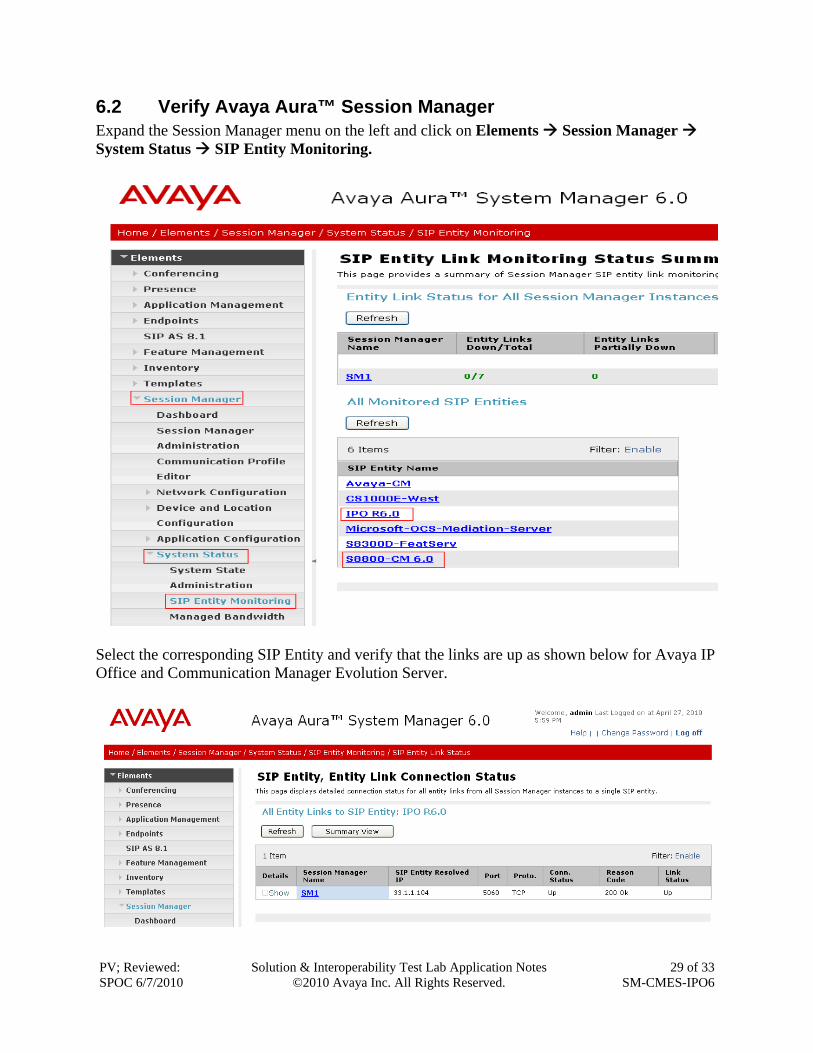
6.2 Verify Avaya Aura™ Session Manager Expand the Session Manager menu on the left and click on Elements Session Manager System Status SIP Entity Monitoring.
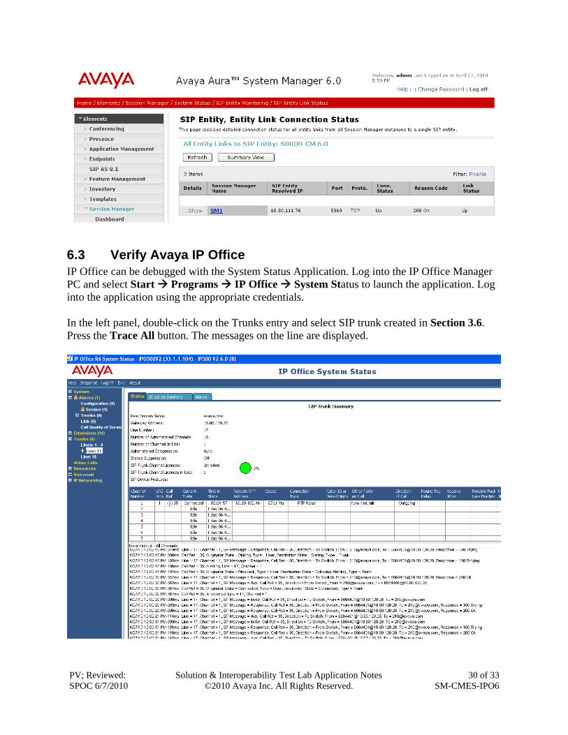
Select the corresponding SIP Entity and verify that the links are up as shown below for Avaya IP Office and Communication Manager Evolution Server.
6.3 Verify Avaya IP Office IP Office can be debugged with the System Status Application. Log into the IP Office Manager PC and select Start Programs IP Office System Status to launch the application. Log into the application using the appropriate credentials. In the left panel, double-click on the Trunks entry and select SIP trunk created in Section 3.6. Press the Trace All button. The messages on the line are displayed.
6.4 Verification Scenarios Verification scenarios for the configuration described in these Application Notes included the following:
1. Basic calls with direct media shuffling (G.711, G.729)
2. Supplementary Calling Features
a. Hold
b. Consultative Hold
c. Call Waiting
d. Attended Transfer
e. Unattended Transfer
f. Call Forward All
g. Conference
Proper display of the calling and called party name and number information was verified for all calls.
7 Conclusion These Application Notes describe how to configure a sample configuration for a network that uses Avaya Aura™ Session Manager Release 6.0 to connect Avaya Aura™ Communication Manager Evolution Server 6.0 and Avaya IP Office Release 6.0 using SIP trunks. Interoperability testing included verification of successful bi-directional calls among several types of endpoints with various features including transfer, and conference.
8 Additional References This section references the product documentation relevant to these Application Notes. Session Manager: [1] Avaya Aura™ Session Manager Overview, Doc ID 03-603323, available at http://support.avaya.com. [2] Installing and Administering Avaya Aura™ Session Manager, Doc ID 03-603324, available at http://support.avaya.com. [3] Maintaining and Troubleshooting Avaya Aura™ Session Manager, Doc ID 03-603325, available at http://support.avaya.com. Communication Manager: [4] SIP Support in Avaya Aura™ Communication Manager Running on Avaya S8xxx
Servers, Doc ID 555-245-206, May 2009, available at http://support.avaya.com.