33
AS/NZS 2492:2007 Australian/New Zealand Standard ™ Cross-linked polyethylene (PE-X) pipes for pressure applications AS/NZS 2492:2007 Accessed by UNIVERSITY OF SOUTH AUSTRALIA on 04 Jun 2008
AS/NZS 2492:2007
Australian/New Zealand Standard™
Cross-linked polyethylene (PE-X) pipes
for pressure applications
AS
/N
ZS
2
49
2:2
00
7
Acc
esse
d by
UN
IVE
RS
ITY
OF
SO
UT
H A
US
TR
ALI
A o
n 04
Jun
200
8
AS/NZS 2492:2007
This Joint Australian/New Zealand Standard was prepared by Joint Technical
Committee PL-006, Polyolefin Pipe Systems. It was approved on behalf of the
Council of Standards Australia on 8 June 2007 and on behalf of the Council of
Standards New Zealand on 9 March 2007.
This Standard was published on 31 July 2007.
The following are represented on Committee PL-006:
AUSTAP
Certification Interests (Australia)
CSIRO Manufacturing and Infrastructure Technology
Energy Networks Association
Engineers Australia
Master Plumbers, Gasfitters and Drainlayers New Zealand
New Zealand Water and Waste Association
Plastics Industry Pipe Association of Australia
Plastics New Zealand
Water Services Association of Australia
Keeping Standards up-to-date
Standards are living documents which reflect progress in science, technology and
systems. To maintain their currency, all Standards are periodically reviewed, and
new editions are published. Between editions, amendments may be issued.
Standards may also be withdrawn. It is important that readers assure themselves
they are using a current Standard, which should include any amendments which
may have been published since the Standard was purchased.
Detailed information about joint Australian/New Zealand Standards can be found by
visiting the Standards Web Shop at www.standards.com.au or Standards New
Zealand web site at www.standards.co.nz and looking up the relevant Standard in
the on-line catalogue.
Alternatively, both organizations publish an annual printed Catalogue with full
details of all current Standards. For more frequent listings or notification of
revisions, amendments and withdrawals, Standards Australia and Standards New
Zealand offer a number of update options. For information about these services,
users should contact their respective national Standards organization.
We also welcome suggestions for improvement in our Standards, and especially
encourage readers to notify us immediately of any apparent inaccuracies or
ambiguities. Please address your comments to the Chief Executive of either
Standards Australia or Standards New Zealand at the address shown on the back
cover.
This Standard was issued in draft form for comment as DR 05364.
Acc
esse
d by
UN
IVE
RS
ITY
OF
SO
UT
H A
US
TR
ALI
A o
n 04
Jun
200
8

AS/NZS 2492:2007
Australian/New Zealand Standard™
Cross-linked polyethylene (PE-X) pipes
for pressure applications
COPYRIGHT
© Standards Australia/Standards New Zealand
All rights are reserved. No part of this work may be reproduced or copied in any form or by
any means, electronic or mechanical, including photocopying, without the written
permission of the publisher.
Jointly published by Standards Australia, GPO Box 476, Sydney, NSW 2001 and Standards
New Zealand, Private Bag 2439, Wellington 6020
ISBN 0 7337 8289 2
Originated as AS 2492—1981.
Second edition 1994.
Jointly revised and designated AS/NZS 2492:2007.
Acc
esse
d by
UN
IVE
RS
ITY
OF
SO
UT
H A
US
TR
ALI
A o
n 04
Jun
200
8

AS/NZS 2492:2007 2
PREFACE
This Standard was prepared by the Joint Standards Australia/Standards New Zealand
Committee PL-006, Polyolefin Pipe Systems, to supersede, in part, AS 2492—1994, Cross-
linked polyethylene (PE-X) pipe for hot and cold water applications, which is withdrawn.
The objective of this Standard is to provide a standard specification for manufacturers and
purchasers of cross-linked polyethylene pipes to be used in pressure applications.
The objective of this revision is to revise the Australian Standard and issue it as a joint
Australian/New Zealand Standard. This revision extends the product applications to general
pressure, including fuel gas, and includes sizes up to DN 1000.
This Standard is based on the latest ISO documents for gas and water applications and,
where appropriate, the principles of AS/NZS 4130 Polyethylene (PE) pipes for pressure
applications and AS/NZS 4131, Polyethylene (PE) compounds for pressure pipes and
fittings have been followed. One exception is the inclusion of the optional addition of
pigment or carbon black masterbatch during extrusion. Appendix A incorporates increased
BRT frequency related to use of the option.
The overall service (design) coefficient of 1.25, taken from ISO 12162, Thermoplastics
materials for pipes and fittings for pressure applications—Classification and designation—
Overall service (design) coefficient, has been applied to establish the hydrostatic design
stress.
The requirements for resistance to slow crack growth and rapid crack propagation are
intended to facilitate the use of PE-X pipes for fuel gas at pressures up to 16 bar and for
general pressure applications without special granular bedding.
The means for demonstrating compliance with this Standard (Appendix A) have been
included for minimum sampling and testing frequency plans to include batch release tests,
process verification tests and type tests requirements, to simplify and improve product
quality verification.
The terms ‘normative’ and ‘informative’ have been used in this Standard to define the
application of the appendix to which they apply. A ‘normative’ appendix is an integral part
of a Standard, whereas an ‘informative’ appendix is only for information and guidance.
Statements expressed in mandatory terms in notes to tables and figures are deemed to be
requirements of this Standard.
Notes to text contain information and guidance. They are not an integral part of the
Standard.
Acc
esse
d by
UN
IVE
RS
ITY
OF
SO
UT
H A
US
TR
ALI
A o
n 04
Jun
200
8
3 AS/NZS 2492:2007
CONTENTS
Page
FOREWORD.............................................................................................................................. 4
SECTION 1 SCOPE AND GENERAL
1.1 SCOPE ........................................................................................................................ 5
1.2 MEANS FOR DEMONSTRATING COMPLIANCE.................................................. 5
1.3 APPLICATION ........................................................................................................... 5
1.4 REFERENCED DOCUMENTS .................................................................................. 5
1.5 DEFINITIONS ............................................................................................................ 5
1.6 MARKING .................................................................................................................. 7
SECTION 2 MATERIALS
2.1 BASE MATERIAL...................................................................................................... 9
2.2 TECHNICAL FILE ..................................................................................................... 9
2.3 PERFORMANCE........................................................................................................ 9
2.4 MATERIAL CLASSIFICATION ................................................................................ 9
2.5 REPROCESSABLE MATERIAL.............................................................................. 11
2.6 SURFACE COATINGS AND STRIPES ................................................................... 12
SECTION 3 PIPES
3.1 FREEDOM FROM DEFECTS .................................................................................. 13
3.2 EFFECT ON FLUID OTHER THAN WATER AND FUEL GAS ............................ 13
3.3 EFFECT ON WATER ............................................................................................... 13
3.4 COLOUR................................................................................................................... 13
3.5 OPACITY.................................................................................................................. 14
3.6 PRESSURE CLASSIFICATION............................................................................... 14
3.7 DIMENSIONS........................................................................................................... 14
3.8 MECHANICAL PROPERTIES................................................................................. 14
3.9 PHYSICAL PROPERTIES........................................................................................ 15
APPENDICES
A MEANS FOR DEMONSTRATING COMPLIANCE WITH THIS STANDARD ..... 20
B OPERATING CONDITIONS FOR PE-X 80 PIPES USED FOR CONVEYANCE
OF HOT AND COLD WATER WITHIN BUILDINGS............................................ 25
C REFERENCED DOCUMENTS ................................................................................ 26
Acc
esse
d by
UN
IVE
RS
ITY
OF
SO
UT
H A
US
TR
ALI
A o
n 04
Jun
200
8
AS/NZS 2492:2007 4
FOREWORD
This Standard describes pipes in terms of dimensional requirements, PE-X material, and
PN rating.
Appendix B tabulates operating parameters for PE-X pipes when used for the conveyance of
hot and cold water within buildings. These parameters are taken from ISO 15875-2, Plastics
piping systems for hot and cold water installations—Crosslinked polyethylene
(PE-X), Part 2: Pipes, along with the pressure test requirements for PE-X 80. Other test
requirements are taken from ISO 14531-1, Plastics pipes and fittings—Crosslinked
polyethylene (PE-X) pipe systems for the conveyance of gaseous fuels—Metric series—
Specifications, Part 1: Pipes.
In this Standard, there is a partial pressure limitation for liquefied petroleum gas (LPG).
The aim of this limitation is to prevent the formation of aliphatic hydrocarbon liquids under
normal service conditions and subsequent deleterious effects on the long-term performance
of the pipe. At a partial pressure of 300 kPa absolute, the dewpoint for a typical propane
LPG is below 0°C. The designer of a cross-linked polyethylene reticulation system should
be aware that if service temperatures lower than this are likely to occur or if LPG
containing significant quantities of butane gases are to be reticulated, the partial pressure
limitation must be revised to avoid condensation of hydrocarbon liquids.
Acc
esse
d by
UN
IVE
RS
ITY
OF
SO
UT
H A
US
TR
ALI
A o
n 04
Jun
200
8

5 AS/NZS 2492:2007
COPYRIGHT
STANDARDS AUSTRALIA/STANDARDS NEW ZEALAND
Australian/New Zealand Standard
Cross-linked polyethylene (PE-X) pipes for pressure applications
S E C T I O N 1 S C O P E A N D G E N E R A L
1.1 SCOPE
This Standard specifies requirements for cross-linked polyethylene pipes for the
conveyance of fluids under pressure. Such fluids include, but are not restricted to, water,
wastewater, slurries, compressed air, and fuel gas. Fuel gas includes natural gas, liquefied
petroleum gas (LPG) in the vapour phase and LPG/air mixtures. The partial pressure of the
LPG is not to exceed 300 kPa absolute.
Pipes intended for the transmission of fuel gas are hereinafter referred to as ‘gas pipes’ and
are not be operated at pressures above 1600 kPa gauge.
1.2 MEANS FOR DEMONSTRATING COMPLIANCE
Compliance with this Standard shall be demonstrated in accordance with Appendix A.
1.3 APPLICATION
This Standard does not apply to gas pipes for use with petroleum liquids, including liquid
LPG and liquid pentane, or with manufactured or mixed gas distribution systems, which
may contain more than 1% aromatics by volume, unless resistance to aromatic constituents
has been demonstrated, as required in Clause 2.3.
Pipes that do not contain carbon black in compliance with this Standard are not intended for
extended exposure in direct sunlight.
PE-X pipe is suitable for use at temperatures up to 100°C as described in Appendix B;
however, continuous long-term operation should be between −50°C and +70°C.
The test requirements specified in this Standard may be achieved by alternative test
methods if such methods can be shown to provide equal or greater accuracy than those
specified herein. In all cases of dispute, the methods specified in this Standard shall be
considered the reference test methods.
1.4 REFERENCED DOCUMENTS
The documents referred to in this Standard are listed in Appendix C:
1.5 DEFINITIONS
For the purpose of this Standard, the definitions given in AS/NZS 3500.0 and those below
apply.
Acc
esse
d by
UN
IVE
RS
ITY
OF
SO
UT
H A
US
TR
ALI
A o
n 04
Jun
200
8
AS/NZS 2492:2007 6
COPYRIGHT
1.5.1 Liquefied petroleum gas (LPG)
A hydrocarbon fluid composed predominantly of any of the following hydrocarbons or
mixtures of all or any of them: propane (C3H
8), propylene (C
3H
6), butane (C
4H
10) or
butylenes (C4H
8) (see Note 1).
NOTES:
1 Unless specifically stated otherwise, any reference to ‘propane’, ‘butane’, or similar means
the commercial grade of that product.
2 The characteristics of the various LP gases, either pure or commercial grades, together with
methods for their determination, are given in the ALPGA publication ‘Liquefied Petroleum
Gas—Specifications and Test Methods’.
1.5.2 Nominal outside diameter (DN)
Numerical designation of size, which is common to all components in a thermoplastics
piping system other than flanges and components designated by thread size.
NOTES:
1 It is a convenient round number for reference purposes.
2 The nominal outside diameter expressed in millimetres is the minimum mean outside diameter
(dem.min
) defined in Clause 1.5.4.
1.5.3 Mean outside diameter (dem
)
Value of the outer circumference of the pipe at any cross-section divided by π, rounded up
to the nearest 0.1 mm.
NOTE: The value for π taken to be 3.142.
1.5.4 Minimum mean outside diameter (dem.min
)
Minimum value of the mean outside diameter of the pipe specified for a given nominal
outside diameter.
1.5.5 Maximum mean outside diameter (dem.max
)
Maximum value of the mean outside diameter of the pipe specified for a given nominal
outside diameter.
1.5.6 Out-of-roundness (ovality)
Difference between the measured maximum outside diameter and the measured minimum
outside diameter in the same cross-sectional plane of the pipe.
1.5.7 Nominal wall thickness (en)
Wall thickness, in millimetres, tabulated in ISO 4065, corresponding to the minimum wall
thickness at any point (ey min
).
1.5.8 Wall thickness at any point (ey)
Measured wall thickness at any point around the circumference of the pipe.
1.5.9 Minimum wall thickness (ey min
)
Minimum permissible value of the wall thickness (ey) at any point around the circumference
of the pipe.
1.5.10 Standard dimension ratio SDR
Ratio of the nominal outside diameter of the pipe to its nominal wall thickness,
SDR = dn/e
n.
Acc
esse
d by
UN
IVE
RS
ITY
OF
SO
UT
H A
US
TR
ALI
A o
n 04
Jun
200
8

7 AS/NZS 2492:2007
COPYRIGHT
1.5.11 Cross-linked polyethylene (PE-X)
Structures within the polyethylene polymer chains that are interconnected by chemical
bonds to create a three-dimensional polymer network.
NOTE: The properties of the three-dimensional structure ensure that it is not possible to melt or
dissolve the polymer. The extent of cross-linking is related to the mass of insoluble material
remaining following solvent extraction and can be determined by measurement of the gel content.
1.5.12 Base material
Physical blend of non-cross-linked polyethylene(s) and additives formulated to facilitate
conversion to PE-X during the production of pipe to meet the requirements of this Standard.
1.5.13 Lower confidence limit of the predicted hydrostatic strength (σLPL
)
Quantity with the dimension of stress, which represents the 97.5% lower confidence limit of
the predicted hydrostatic strength at a temperature θ and a time t in water.
NOTE: It is denoted as σLPL
=σθ, t, 0.975
.
1.5.14 Long-term hydrostatic strength (σLTHS
)
Quantity, with the dimensions of stress, which represents the predicted mean strength at a
temperature (θ ) and time (t) in water.
1.5.15 Minimum required strength (MRS)
Value of σLPL
at a temperature of 20ºC and a time of 50 years [σ(20°C, 50 years, 0.975)],
rounded down to the nearest lower value of the R10 or R20 series as specified in ISO 3 and
ISO 497, depending on the value of σLPL
.
1.5.16 Nominal pressure (PN)
A numerical designation used for reference purposes, related to the mechanical
characteristics of the component of a piping system. For plastics piping systems conveying
water it corresponds to the maximum continuous operating pressure in bar, which can be
sustained with water at 20°C, based on the minimum design coefficient.
1.5.17 Overall service (design) coefficient (C)
Overall coefficient, with a value greater than 1, that takes into consideration service
conditions as well as properties of the components of a piping system other than those
represented in σLPL
.
NOTE: ISO 12162 specifies a minimum permissible service (design) coefficient of 1.25 for PE-X
pipes.
1.6 MARKING
Marking details shall be legibly printed or formed directly on the pipe. Marking of pipes
shall not initiate cracks or other types of failure and, with normal storage, weathering and
processing, and the permissible method of installation and use, legibility shall be
maintained for the life of the pipes.
Letters shall be of a minimum height of 3 mm for pipes up to and including nominal outside
diameter 32 mm, and 5 mm for larger sizes.
Marking shall be repeated at intervals such that the distance between markings is not
greater than 1 m. Marking shall show the following:
(a) Manufacturer’s name or registered trademark.
(b) For gas pipes, nominal diameter and SDR, in the form ‘DN 25 SDR 9 GAS’, as
appropriate.
(c) For pipes other than gas pipes, nominal diameter, classification and SDR, in the form
‘DN 25 PN 16 SDR 9’.
Acc
esse
d by
UN
IVE
RS
ITY
OF
SO
UT
H A
US
TR
ALI
A o
n 04
Jun
200
8
AS/NZS 2492:2007 8
COPYRIGHT
(d) PE-X material classification number in the form ‘PE-X* 100’, as appropriate, where
‘*’ represents material cross-linked by—
(i) peroxide—PE-Xa
(ii) silane—PE-Xb
(iii) electron beam—PE-Xc
(e) Date of manufacture in the form ‘070515’, i.e., the 15th of May, 2007, as appropriate.
(f) Identification of the place of manufacture.
(g) The number of this Standard, i.e., AS/NZS 2492.
NOTES:
1 The manufacturer’s code is acceptable, e.g., F1.
2 For specific applications additional marking may be required as specified in the relevant
installation code.
3 Manufacturers making a statement of compliance with this Australian/New Zealand Standard
on a product, packaging, or promotional material related to that product are advised to ensure
that such compliance is capable of being verified.
Examples of mandatory marking:
TRADE MARK DN 25 PN 16 SDR 9 PE-Xa 100 040515 F1 AS/NZS 2492.
Acc
esse
d by
UN
IVE
RS
ITY
OF
SO
UT
H A
US
TR
ALI
A o
n 04
Jun
200
8
9 AS/NZS 2492:2007
COPYRIGHT
S E C T I O N 2 M A T E R I A L S
2.1 BASE MATERIAL
2.1.1 General
Base material used in the manufacture of pipes, which meets the performance requirements
described in Clause 2.3, shall be cross-linked by the peroxide (PE-Xa), silane (PE-Xb) or
electron beam (PE-Xc) cross-linking process or, subject to consultation with the pipeline
operator, by another process.
The base material shall be fully compounded prior to extrusion, with the exception of–
(a) those additions necessary for the acceleration of cross-linking;
(b) the optional addition of pigment or carbon black masterbatch; and
(c) PE-Xa, where all materials are blended in powder form prior to extrusion.
The addition of pigment or carbon black masterbatch during extrusion shall not be an option
for cross-linkable pipes, i.e., those that achieve the degree of cross-linking during or after
installation.
2.1.2 Carbon black
When determined in accordance with ISO 6964, black polyethylene compounds shall
contain 2.25 ± 0.25% by mass of carbon black.
When determined in accordance with ASTM D3849 or equivalent, the average particle size
of carbon black shall be in the range of 10 to 25 nm.
When determined in accordance with AS/NZS 1462.27, the toluene extract of carbon black
shall be not greater than 0.1%.
NOTE: Type P carbon blacks are known to be capable of meeting this requirement.
2.2 TECHNICAL FILE
The manufacturer of the pipe shall maintain the availability of a technical file (generally
confidential) with all relevant material data to prove the conformity of pipes to this
Standard. It shall include all the results of type testing. Any change in the materials used,
which is likely to affect the product quality and performance, shall require a reassessment
of material performance against the requirements of this Standard.
2.3 PERFORMANCE
PE-X shall conform to the performance requirements given in Tables 1 and 2 when tested in
the form of pipe. Conformity shall be demonstrated by the pipe manufacturer and shall
relate to one source of base material and associated pipe manufacturing method.
2.4 MATERIAL CLASSIFICATION
2.4.1 General
Classification testing and evaluation shall be undertaken in accordance with ISO 1167 (or
AS 1462.6), ISO 12162, and ISO 9080 (or AS/NZS 1462.29), plus specific additional
requirements for PE-X 80 detailed in Clause 2.4.3.
Acc
esse
d by
UN
IVE
RS
ITY
OF
SO
UT
H A
US
TR
ALI
A o
n 04
Jun
200
8
AS/NZS 2492:2007 10
COPYRIGHT
2.4.2 Predictive relationship
The test data generated (pipe stress applied and failure time), covering the temperature
range 20°C to 100°C, shall be used to derive the following predictive relationship between
the long-term hydrostatic strength (σLTHS
), failure time and temperature:
logt = A + BlogσLTHS
/θ + C/θ + DlogσLTHS
. . . E(1)
where
θ = temperature, in Kelvin
t = time, in hours
σL = long-term hydrostatic strength, in megapascals
A, B, C, and D are coefficients determined from experimental data.
The relationships between time, stress and temperature thus derived shall be used to obtain
the value of one unknown when the other two variables are known.
2.4.3 Additional requirements for PE-X 80
For PE-X 80 pipes, the values of A, B, C, and D obtained from testing and evaluation in
accordance with ISO 9080 or AS/NZS 1462.29 shall be −105.8618, −18506.15, 57895.49,
and −24.7997 respectively, or other values that yield higher stress.
NOTE: Appendix B provides specific examples of operating conditions for PE-X 80 pipes.
2.4.4 Provisional qualification
Prior to establishment of classification, provisional qualification as PE-X 80 may be
afforded to products that meet the 1000 h, 95°C hydrostatic strength requirements for
PE-X 100 (see Note). Similarly, provisional qualification may be afforded to PE-X 100
products that meet the 1000 h, 95°C hydrostatic strength requirements for PE-X 125.
However, provisional qualification shall not be afforded to PE-X 125 products.
NOTE: Mechanical properties of pipes are specified in Table 3.3.
Acc
esse
d by
UN
IVE
RS
ITY
OF
SO
UT
H A
US
TR
ALI
A o
n 04
Jun
200
8
11 AS/NZS 2492:2007
COPYRIGHT
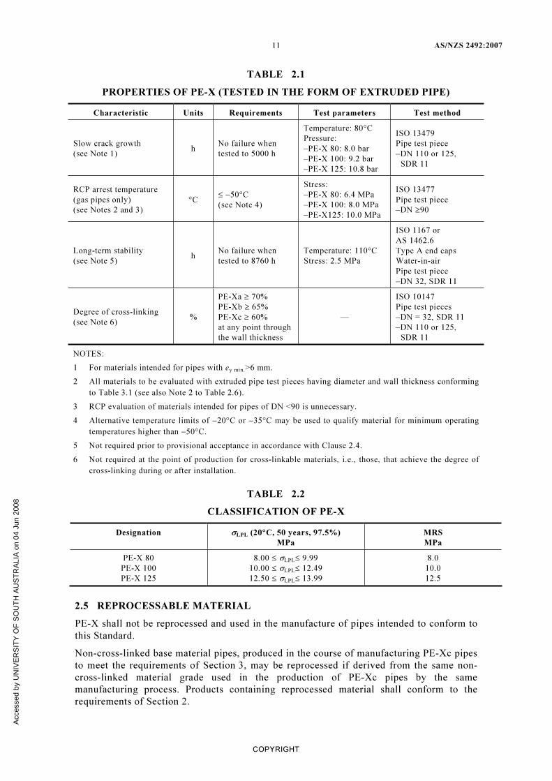
TABLE 2.1
PROPERTIES OF PE-X (TESTED IN THE FORM OF EXTRUDED PIPE)
Characteristic Units Requirements Test parameters Test method
Slow crack growth
(see Note 1)
h
No failure when
tested to 5000 h
Temperature: 80°C
Pressure:
–PE-X 80: 8.0 bar
–PE-X 100: 9.2 bar
–PE-X 125: 10.8 bar
ISO 13479
Pipe test piece
–DN 110 or 125,
SDR 11
RCP arrest temperature
(gas pipes only)
(see Notes 2 and 3)
°C
≤ −50°C
(see Note 4)
Stress:
–PE-X 80: 6.4 MPa
–PE-X 100: 8.0 MPa
–PE-X125: 10.0 MPa
ISO 13477
Pipe test piece
–DN ≥90
Long-term stability
(see Note 5)
h
No failure when
tested to 8760 h
Temperature: 110°C
Stress: 2.5 MPa
ISO 1167 or
AS 1462.6
Type A end caps
Water-in-air
Pipe test piece
–DN 32, SDR 11
Degree of cross-linking
(see Note 6)
%
PE-Xa ≥ 70%
PE-Xb ≥ 65%
PE-Xc ≥ 60%
at any point through
the wall thickness
—
ISO 10147
Pipe test pieces
–DN = 32, SDR 11
–DN 110 or 125,
SDR 11
NOTES:
1 For materials intended for pipes with ey min.
>6 mm.
2 All materials to be evaluated with extruded pipe test pieces having diameter and wall thickness conforming
to Table 3.1 (see also Note 2 to Table 2.6).
3 RCP evaluation of materials intended for pipes of DN <90 is unnecessary.
4 Alternative temperature limits of −20°C or −35°C may be used to qualify material for minimum operating
temperatures higher than −50°C.
5 Not required prior to provisional acceptance in accordance with Clause 2.4.
6 Not required at the point of production for cross-linkable materials, i.e., those, that achieve the degree of
cross-linking during or after installation.
TABLE 2.2
CLASSIFICATION OF PE-X
Designation σLPL
(20°C, 50 years, 97.5%)
MPa
MRS
MPa
PE-X 80
PE-X 100
PE-X 125
8.00 ≤ σLPL
≤ 9.99
10.00 ≤ σLPL
≤ 12.49
12.50 ≤ σLPL
≤ 13.99
8.0
10.0
12.5
2.5 REPROCESSABLE MATERIAL
PE-X shall not be reprocessed and used in the manufacture of pipes intended to conform to
this Standard.
Non-cross-linked base material pipes, produced in the course of manufacturing PE-Xc pipes
to meet the requirements of Section 3, may be reprocessed if derived from the same non-
cross-linked material grade used in the production of PE-Xc pipes by the same
manufacturing process. Products containing reprocessed material shall conform to the
requirements of Section 2.
Acc
esse
d by
UN
IVE
RS
ITY
OF
SO
UT
H A
US
TR
ALI
A o
n 04
Jun
200
8

AS/NZS 2492:2007 12
COPYRIGHT
2.6 STRIPES AND JACKETS
2.6.1 General
Materials used for external jackets or stripes, e.g., for colour-coded end use identification
systems, shall comply with Clause 2.1.
2.6.2 Cohesive resistance
Jacketed and striped pipe of any diameter shall be tested in accordance with ISO 13954.
Decohesion between jacket or stripe and parent pipe shall not occur over more than 30% of
the socket fusion zone as defined in AS/NZS 4129.
NOTE: It is recognized that ISO 13954 relates to diameters 90 and above; however, for the
purpose of this Standard, it is also to be applied for smaller diameters.
Acc
esse
d by
UN
IVE
RS
ITY
OF
SO
UT
H A
US
TR
ALI
A o
n 04
Jun
200
8
13 AS/NZS 2492:2007
COPYRIGHT
S E C T I O N 3 P I P E S
3.1 FREEDOM FROM DEFECTS
3.1.1 General
Defects shall not affect the performance or function of the pipe in service. Pipes shall not
have any blisters, voids, burnt particles or heat marks. When grooves, wrinkles, rippling,
dents or projections are present, the pipe shall comply with the dimensional requirements of
Table 3.1. Where defects are present and the product is submitted for acceptance, the
manufacturer shall be able to demonstrate its conformance to this Standard.
The defects described above cannot be completely quantified. Where the presence, size or
frequency of any of these are considered to be of concern, arrangements should be made
between the purchaser/approving authority/certifying body (as appropriate), and the
manufacturer. This may be achieved by the provision of acceptable type samples or
methods of test.
3.1.2 Pipe ends
Pipe ends shall not have any chips, burrs or rough edges and shall be nominally square.
3.1.3 Cleanliness
Pipes shall be internally clean and free from swarf and other manufacturing debris.
3.2 EFFECT ON FLUID OTHER THAN WATER AND FUEL GAS
Where fluids other than water and fuel gas are to be conveyed, the effect on the fluid shall
be established by reference to the pipe manufacturer.
3.3 EFFECT ON WATER
This Clause is not applicable to pipes intended for conveyance of fuel gas.
Blue and purple pipes shall comply with AS/NZS 4020 with a scaling factor of 1.
3.4 COLOUR
3.4.1 General
Yellow, purple and blue pipes, stripes and jackets shall meet the colour requirements of
Clauses 3.4.2 to 3.4.4, respectively.
NOTE: Information on the RAL colour range may be obtained from RAL Deutsches Institut für
Gütesicherung und Kennzeichnung e.V., www.ral.de.
Colour requirements for products of other colours shall be as agreed between the purchaser
and the manufacturer.
3.4.2 Yellow (gas)
The colour of yellow stripes or jackets shall be as follows:
(a) PE-X 80, no darker than RAL 1018.
(b) PE-X 100 and PE-X 125, no lighter than RAL 1033.
3.4.3 Blue (drinking water)
The colour of blue stripes or jackets shall be as follows:
(a) PE-X 80, no darker than RAL 5012.
(b) PE-X 100 and PE-X 125, no lighter than RAL 5005.
Acc
esse
d by
UN
IVE
RS
ITY
OF
SO
UT
H A
US
TR
ALI
A o
n 04
Jun
200
8

AS/NZS 2492:2007 14
COPYRIGHT
3.4.4 Purple (recycled water)
The colour of purple pipes, stripes and jackets shall be purple neither lighter than
RAL 310 70 15, nor darker than RAL 330 40 40 or RAL 310 50 30.
3.5 NUMBER AND COVERAGE OF STRIPES (IF ANY)
Striped pipes shall have a minimum number of four stripes.
For pipes DN <280, not less than 15% of the external pipe surface shall be covered by the
striping material.
For pipes DN ≥280 and DN <630, the percentage coverage shall be not less than 10% of the
external pipe surface.
For pipes DN ≥630, the coverage shall be not less than 8% of the external pipe surface.
3.6 OPACITY
Pipes for drinking water based applications shall not transmit more than 0.2% of visible
light when tested in accordance with ISO 7686.
3.7 PRESSURE CLASSIFICATION
Pipes for applications other than gas are classified in terms of the nominal pressure rating
(PN) at material service temperature of 20°C, as follows:
PN 8 Nominal working pressure of 0.80 MPa
PN 10 Nominal working pressure of 1.00 MPa
PN 12.5 Nominal working pressure of 1.25 MPa
PN 16 Nominal working pressure of 1.60 MPa
PN 20 Nominal working pressure of 2.00 MPa
PN 25 Nominal working pressure of 2.50 MPa
Pipes for gas applications are classified according to SDR.
Standard dimension ratios for pipes made from PE-X 80, PE-X 100, and PE-X 125
compounds are given in Table 3.2.
3.8 DIMENSIONS
3.8.1 Diameter and wall thickness
The thickness at any point shall not fall below the minimum specified in Table 3, as
appropriate to the DN and SDR, and the average thickness shall not exceed the maximum
specified. When measured at a distance not less than 5% of DN from the cut end of the
pipe, in accordance with AS/NZS 1462.1, the mean outside diameter (Dm
) shall comply
with the requirements of Tables 3.1(A), 3.1(B) and 3.1(C).
3.8.2 Coiled pipe
The internal diameter for a coil of pipe shall be such that kinking is prevented.
3.8.3 Out of roundness
Ovality requirements shall apply at the time of manufacture and before coiling.
3.9 MECHANICAL PROPERTIES
Pipes shall conform to the mechanical performance requirements given in Table 3.3.
Acc
esse
d by
UN
IVE
RS
ITY
OF
SO
UT
H A
US
TR
ALI
A o
n 04
Jun
200
8

15 AS/NZS 2492:2007
COPYRIGHT
3.10 PHYSICAL PROPERTIES
When tested in accordance with the methods given in Table 3.4 using the parameters
specified, pipes shall conform to the requirements in Table 3.4.
TABLE 3.1(A)
DIMENSIONS OF PIPES—SDR 17 AND SDR 13.6
millimetres
SDR 17 SDR 13.6
Mean outside
diameter
(dem
)
Wall thickness
(T)
Mean inside
diameter
(DI)
Wall thickness
(T)
Mean inside
diameter
(DI)
Nominal
outside
diameter
(DN)
Min. Max.
Maximum
out-of-
roundness
Min. Max. Min. Max. Min. Max. Min. Max.
16
20
25
16.0
20.0
25.0
16.3
20.3
25.3
1.2
1.2
1.2
—
—
1.6
—
—
1.9
—
—
21.2
—
—
22.1
—
1.6
1.9
—
1.9
2.2
—
16.2
20.6
—
17.1
21.5
32
40
50
32.0
40.0
50.0
32.3
40.4
50.5
1.3
1.4
1.4
1.9
2.2
3.0
2.2
2.8
3.4
27.6
34.4
43.2
28.5
35.6
44.5
2.4
3.0
3.7
2.8
3.4
4.2
26.4
33.2
41.6
27.5
34.4
43.1
63
75
90
63.0
75.0
90.0
63.6
75.7
90.9
1.5
1.6
1.8
3.8
4.5
5.4
4.3
5.1
6.1
54.4
64.8
77.8
56.0
66.7
80.1
4.7
5.5
6.6
5.3
6.2
7.4
52.4
62.6
75.2
54.2
64.7
77.7
110
125
140
110.0
125.0
140.0
111.0
126.2
141.3
2.2
2.5
2.8
6.6
7.4
8.3
7.4
8.3
9.3
95.2
108.4
121.4
97.8
111.4
124.7
8.1
9.2
10.3
9.1
10.3
11.5
91.8
104.4
117.0
94.8
107.8
120.7
160
180
200
160.0
180.0
200.0
161.5
181.7
201.8
3.2
3.6
4.0
9.5
10.7
11.9
10.6
11.9
13.2
138.8
156.2
173.6
142.5
160.3
178.0
11.8
13.3
14.7
13.1
14.8
16.3
133.8
150.4
167.4
137.9
155.1
172.4
225
250
280
225.0
250.0
280.0
227.1
252.3
282.6
4.5
5.0
9.8
13.4
14.8
16.6
14.9
16.4
18.4
195.2
217.2
243.2
200.3
222.7
249.4
16.6
18.4
20.6
18.4
20.4
22.8
188.2
209.2
234.4
193.9
215.5
241.4
315
355
400
315.0
355.0
400.0
317.9
358.2
403.6
11.1
12.5
14.0
18.7
21.1
23.7
20.7
23.4
26.2
273.6
306.2
347.6
280.5
316.0
356.2
23.2
26.1
29.4
25.7
28.9
32.5
263.6
297.2
335.0
271.5
306.0
344.8
450
500
560
450.0
500.0
560.0
454.1
504.5
565.0
15.6
17.5
19.6
26.7
29.6
33.2
29.5
32.7
36.7
391.0
434.6
486.6
400.7
445.3
498.7
33.1
36.8
41.2
36.6
40.6
45.5
376.8
418.8
469.0
387.9
430.9
482.7
630
710
800
630.0
710.0
800.0
635.7
716.4
807.2
22.1
24.9
28.0
37.3
42.1
47.4
41.2
46.5
52.3
547.6
617.0
695.4
561.1
632.2
712.4
46.3
52.2
58.8
51.1
57.6
64.8
527.8
594.8
670.4
543.1
612.0
689.6
900
1000
900.0
1000.0
908.1
1009.0
31.5
35.0
53.5
59.3
59.0
65.4
782.2
869.2
801.1
890.4
—
—
—
—
—
—
—
—
Acc
esse
d by
UN
IVE
RS
ITY
OF
SO
UT
H A
US
TR
ALI
A o
n 04
Jun
200
8

AS/NZS 2492:2007 16
COPYRIGHT
TABLE 3.1(B)
DIMENSIONS OF PIPES—SDR 11 AND SDR 9
millimetres
SDR 11 SDR 9
Mean outside
diameter
(dem
)
Wall thickness
(T)
Mean inside
diameter
(DI)
Wall thickness
(T)
Mean inside
diameter
(DI)
Nominal
outside
diameter
(DN)
Min. Max.
Maximum
out-of-
roundness
Min. Max. Min. Max. Min. Max. Min. Max.
16
20
25
16.0
20.0
25.0
16.3
20.3
25.3
1.2
1.2
1.2
—
1.9
2.3
—
2.2
2.7
—
15.6
19.6
—
16.5
20.7
2.0
2.3
2.8
2.3
2.7
3.2
11.4
14.6
18.6
12.3
15.7
19.7
32
40
50
32.0
40.0
50.0
32.3
40.4
50.5
1.3
1.4
1.4
2.9
3.7
4.6
3.3
4.2
5.2
25.4
31.6
39.6
26.5
33.0
41.2
3.6
4.5
5.6
4.1
5.1
6.3
23.8
29.8
37.4
25.1
31.4
39.3
63
75
90
63.0
75.0
90.0
63.6
75.7
90.9
1.5
1.6
1.8
5.8
6.8
8.2
6.5
7.6
9.2
50.0
59.8
71.6
52.0
62.1
74.5
7.1
8.4
10.1
8.0
9.4
11.3
47.0
56.2
67.4
49.4
58.9
70.7
110
125
140
110.0
125.0
140.0
111.0
126.2
141.3
2.2
2.5
2.8
10.0
11.4
12.7
11.1
12.7
14.1
87.8
99.6
111.8
91.0
103.4
115.9
12.3
14.0
15.7
13.7
15.5
17.4
82.6
94.0
105.2
86.4
98.2
109.9
160
180
200
160.0
180.0
200.0
161.5
181.7
201.8
3.2
3.6
4.0
14.6
16.4
18.2
16.2
18.2
20.2
127.6
143.6
159.6
132.3
148.9
165.4
17.9
20.1
22.4
19.8
22.3
24.8
120.4
135.4
150.4
125.7
141.5
157.0
225
250
280
225.0
250.0
280.0
227.1
252.3
282.6
4.5
5.0
9.8
20.5
22.7
25.4
22.7
25.1
28.1
179.6
199.8
223.8
186.1
206.9
231.8
25.1
27.9
31.3
27.8
30.8
34.6
169.4
188.4
210.8
176.9
196.5
220.0
315
355
400
315.0
355.0
400.0
317.9
358.2
403.6
11.1
12.5
14.0
28.6
32.2
36.3
31.6
35.6
40.1
251.8
283.8
319.8
260.7
293.8
331.0
35.2
39.6
44.7
38.9
43.7
49.3
237.2
267.6
301.4
247.5
279.0
314.2
450
500
560
450.0
500.0
560.0
454.1
504.5
565.0
15.6
17.5
19.6
40.9
45.4
50.8
45.1
50.1
56.0
359.8
399.8
448.0
372.3
413.7
463.5
50.2
—
—
55.4
—
—
339.2
—
—
353.7
—
—
630
710
800
630.0
710.0
800.0
635.7
716.4
807.2
22.1
24.9
28.0
57.2
—
—
63.1
—
—
503.8
—
—
521.3
—
—
—
—
—
—
—
—
—
—
—
—
—
—
900
1000
900.0
1000.0
908.1
1009.0
31.5
35.0
—
—
—
—
—
—
—
—
—
—
—
—
—
—
—
—
Acc
esse
d by
UN
IVE
RS
ITY
OF
SO
UT
H A
US
TR
ALI
A o
n 04
Jun
200
8

17 AS/NZS 2492:2007
COPYRIGHT
TABLE 3.1(C)
DIMENSIONS OF PIPES—SDR 7.4
millimetres
SDR 7.4 Mean outside
diameter
(dem
)
Wall thickness
(T)
Mean inside
diameter
(DI)
Nominal
outside
diameter
(DN)
Min. Max.
Maximum
out-of-
roundness
Min. Max. Min. Max.
16
20
25
16.0
20.0
25.0
16.3
20.3
25.3
1.2
1.2
1.2
2.2
2.8
3.5
2.6
3.2
4.0
10.8
13.6
17.0
11.9
14.7
18.3
32
40
50
32.0
40.0
50.0
32.3
40.4
50.5
1.3
1.4
1.4
4.4
5.5
6.9
5.0
6.2
7.7
22.0
27.6
34.6
23.5
29.4
36.7
63
75
90
63.0
75.0
90.0
63.6
75.7
90.9
1.5
1.6
1.8
8.6
10.3
12.3
9.6
11.5
13.7
43.8
52.0
62.6
46.4
55.1
66.3
110
125
140
110.0
125.0
140.0
111.0
126.2
141.3
2.2
2.5
2.8
15.1
17.1
19.2
16.8
19.0
21.3
76.4
87.0
97.4
80.8
92.0
102.9
160
180
200
160.0
180.0
200.0
161.5
181.7
201.8
3.2
3.6
4.0
21.9
24.6
27.3
24.2
27.2
30.2
111.6
125.6
139.6
117.7
132.5
147.2
225
250
280
225.0
250.0
280.0
227.1
252.3
282.6
4.5
5.0
9.8
30.8
34.2
38.3
34.0
37.8
42.3
157.0
174.4
195.4
165.5
183.9
206.0
315
355
400
315.0
355.0
400.0
317.9
358.2
403.6
11.1
12.5
14.0
43.0
48.5
54.6
47.4
53.5
60.2
220.2
248.0
279.9
231.9
261.2
294.45
450
500
560
450.0
500.0
560.0
454.1
504.5
565.0
15.6
17.5
19.6
61.5
—
—
67.8
—
—
314.4
—
—
331.1
—
—
630
710
800
630.0
710.0
800.0
635.7
716.4
807.2
22.1
24.9
28.0
—
—
—
—
—
—
—
—
—
—
—
—
900
1000
900.0
1000.0
908.1
1009.0
31.5
35.0
—
—
—
—
—
—
—
—
TABLE 3.2
STANDARD DIMENSION RATIOS (SDRs)
Compound PN 8 PN 10 PN 12.5 PN 16 PN 20 PN 25
PE-X 80
PE-X 100
PE-X 125
17
—
—
13.6
17
—
11
13.6
17
9
11
13.6
7.4
9
11
—
7.4
—
Acc
esse
d by
UN
IVE
RS
ITY
OF
SO
UT
H A
US
TR
ALI
A o
n 04
Jun
200
8

AS/NZS 2492:2007 18
COPYRIGHT
TABLE 3.3
MECHANICAL PROPERTIES OF PIPES
Characteristic Units Requirements Test parameters Test method
No failure when tested
to 1000 h
(see Note 1)
Temperature: 20°C
Stress:
–PE-X 80: 8.3 Mpa
–PE-X 100: 10.4 Mpa
–PE-X 125: 13.0 MPa
No failure when tested
to 165 h
Temperature: 95°C
Stress:
–PE-X 80: 4.6 Mpa
–PE-X 100: 4.8 Mpa
–PE-X 125: 6.0 MPa
No failure when tested
to 1000 h
Temp: 95°C
Stress:
–PE-X 80: 4.4 Mpa
–PE-X 100: 4.7 Mpa
–PE-X 125: 5.9 MPa
Hydrostatic strength h
No failure when tested
to 1 h
Temperature 95°C
Stress: PE-X 80: 4.8 MPa
ISO 1167 or
AS 1462.6
Type A end caps
Water-in-water
Elongation at break % ≥ 350% —
ISO 6259-1,
ISO 6259-3
RCP arrest
temperature
(gas pipes only)
(see Note 2)
°C
≤ −50°C
(see Note 3)
Stress:
–PE-X 0: 6.4 Mpa
–PE-X 00: 8.0 Mpa
–PE-X 25: 10.0 MPa
ISO 13477
Slow crack growth
(see Note 4)
h
No failure when tested
to 5000 h
Temperature: 80°C
Pressure (see Note 5):
–PE-X 80: 8.0 bar
–PE-X 100: 9.2 bar
–PE-X 125: 10.8 bar
ISO 13479
NOTES:
1 Conducting tests at 20°C for 100 h at a stress level agreed between the manufacturer and pipeline
operator is permissible if correlation with 1000 h data can be demonstrated.
2 For pipes of dn≥90 mm. Testing is only required for gas pipes and when the wall thickness of the pipe is
greater than the wall thickness of the pipe used in the rapid crack propagation test on the PE-X compound
(see Note to Table 2.1). Tests shall be carried out on the thickest walled pipe in the manufacturer’s range.
For large diameter thick walled pipe, ISO 13478 may be used.
3 Alternative temperatures of −20°C or −35°C may be used to qualify material for minimum operating
temperatures higher than −50°C.
4 For pipes of en >6 mm, for quality control, conducting tests for 165 h at 95°C and a pressure agreed
between the manufacturer and pipeline operator is permissible if correlation with 80°C data can be
demonstrated.
5 The test pressures stated are for SDR 11 pipes. Guidance regarding test pressures for pipes of other SDR
values is given in ISO 13479.
Acc
esse
d by
UN
IVE
RS
ITY
OF
SO
UT
H A
US
TR
ALI
A o
n 04
Jun
200
8

19 AS/NZS 2492:2007
COPYRIGHT
TABLE 3.4
PHYSICAL PROPERTIES OF PIPES
Characteristic Units Requirements Test
parameters
Test method
Degree of cross-
linking (see
Note 1)
%
Manufacturer’s declared value
(≥60 but ≤90)
ISO 10147
(see Note 2)
Carbon black or
pigment
dispersion (see
Note 3)
—≤Grade 3
Rating of appearance A1, A2, A3 or B
ISO 18553
Thermal
stability
min. ≥20
200°C
(see Note 4)
ISO/TR 10837
Resistance to
weathering
(see Note 5)
—
As indicated by change in:
–Thermal stability (see Note 6)
–95°C hydrostatic strength
–Elongation at break
E ≥3.5 GJ/m2
ISO 14531-1,
Annex C
Longitudinal
reversion
%
≤3%
No change in appearance
110°C ISO 2505
NOTES:
1 Not required at the point of production for cross-linkable materials, i.e., those that achieve the degree of
cross-linking during or after installation.
2 Test pieces of radial thickness 0.1 mm shall be used for measurement of degree of cross-linking. They
shall be taken from the outer and inner pipe surfaces and the mid-wall position.
3 Only pipe layers with pigmentation should be used for grade classification.
4 Testing at 210°C is permissible if correlation with 200°C data can be demonstrated. In cases of dispute,
testing shall be carried out at 200°C.
5 Not applicable to the following:
(a) Carbon black pigmented pipes or external layers where the carbon content is greater than 2% when
determined in accordance with ISO 6964.
(b) Internal pipe surfaces.
6 Test pieces shall be taken from the outer pipe surface after preparation for fusion jointing either by
scraping to remove a layer 0.2 mm thick or by removal of the protective surface coating, as appropriate.
Acc
esse
d by
UN
IVE
RS
ITY
OF
SO
UT
H A
US
TR
ALI
A o
n 04
Jun
200
8

AS/NZS 2492:2007 20
COPYRIGHT
APPENDIX A
MEANS FOR DEMONSTRATING COMPLIANCE WITH THIS STANDARD
(Normative)
A1 SCOPE
This Appendix sets out two means by which compliance with this has to be demonstrated by
a manufacturer as follows:
(a) The use of a product certification scheme.
(b) The use of a minimum sampling and testing frequency plan.
A2 RELEVANCE
The long-term performance of pipeline systems is critical to the operating efficiency of
water and gas agencies in terms of operating licences and customer contracts. The long-
term performance of plumbing systems is similarly critical to the durability of building
infrastructure, protection of public health and safety and protection of the environment.
A3 DEFINITIONS
A3.1 Acceptable quality level (AQL)
When a continuous series of lots or batches is considered, the quality level which, for the
purpose of sampling inspection, is the limit of a satisfactory process average
(see AS 1199.1).
NOTE: The designation of an AQL does not imply that a manufacturer has the right knowingly to
supply any non-conforming unit of product.
A3.2 Batch
Schedule of pipes, all of the same nominal diameter, wall thickness and marking,
manufactured from the same material or compound on the same machine.
NOTE: The batch is defined and identified by the pipe manufacturer.
A3.3 Batch release test (BRT)
A test performed on a sample from the batch or lot, to confirm conformance to the
requirements of this Standard before the batch can be released.
A3.4 Inspection level
The relationship between the batch or lot size and the sample size (see AS 1199.1).
A3.5 Lot
A clearly identifiable subdivision of a batch for inspection purposes.
A3.6 New material formulation
Any of the following changes:
(a) Change of polymer, that is—
(i) change of supplier,
(ii) change of polymerization, or
(iii) change of chemical properties of comonomers.
Acc
esse
d by
UN
IVE
RS
ITY
OF
SO
UT
H A
US
TR
ALI
A o
n 04
Jun
200
8

21 AS/NZS 2492:2007
COPYRIGHT
(b) Change of additive package (e.g. pigments, antioxidants), that is—
(i) change of amount greater than ± 30% of individual additive;
(ii) change of chemical properties; or
(iii) change of nature of additive.
A3.7 Process verification test (PVT)
A test performed on a sample at specific intervals, to confirm conformance to the
requirements of this Standard before further batches can be released.
A3.8 Sample
One or more units of product drawn from a batch or lot, selected at random without regard
to quality.
NOTE: The number of units of product in the sample is the sample size.
A3.9 Sampling plan
A specific plan that gives the number of samples and the frequency of inspection or testing.
A3.10 Type test (TT)
A test performed on a sample to confirm conformance to the requirements of this Standard
before any batches can be released.
A4 PRODUCT CERTIFICATION
The purpose of product certification is to provide independent assurance of the claim by the
manufacturer that products comply with this Standard.
The certification scheme shall meet the criteria described in SA HB 18.28/SANZ HB 18.28
(ISO/IEC Guide 28) in that, as well as full type testing from independently sampled
production and subsequent verification of conformance, it requires the manufacturer to
maintain effective planning to control production.
The certification scheme serves to indicate that the products consistently conform to the
requirements of this Standard.
Product certification shall be conducted by a certification body accredited by the Joint
Accreditation System for Australia and New Zealand (JAS-ANZ) or by another certification
body that is acceptable to JAS-ANZ.
The frequency of the sampling and testing plan, as detailed in Paragraph A5, shall be used
by the certifying body for product compliance auditing. However, where the manufacturer
can demonstrate adequate process control to the certifying body, the frequency of sampling
and testing nominated in the manufacturer’s quality and/or documented procedures shall
take precedence for the purpose of product certification.
A5 MINIMUM SAMPLING AND TESTING FREQUENCY PLAN
A5.1 General
Table A1 sets out the minimum sampling and testing frequency plan for a manufacturer to
demonstrate compliance of product(s) to this Standard.
Acc
esse
d by
UN
IVE
RS
ITY
OF
SO
UT
H A
US
TR
ALI
A o
n 04
Jun
200
8
AS/NZS 2492:2007 22
COPYRIGHT
A5.2 Retesting
In the event of a test failure, the products manufactured since the previous test(s)
conforming to the requirements outlined in Table A1 shall be quarantined as a batch. A
further set of samples shall be selected randomly from the quarantined batch using a
sampling plan to AS 1199.1 for an acceptable quality level (AQL) of 2.5 and an inspection
level of S3, unless otherwise specified. If the retest requirements are met, the batch may be
released and compliance with this Standard for the quarantined batch may be claimed.
Should a failure occur on retesting, then the quarantined batch shall be rejected and claims
and/or marking indicating compliance to this Standard shall be suspended until the cause of
the failure has been identified and corrected.
A5.3 Rejection after test
In the event of a quarantined batch being rejected after retesting in accordance with the
procedures set out in Paragraph A5.2, it may be subjected to 100% testing for the failed
requirement(s), and only those items found to comply may be claimed and/or marked as
complying with this Standard.
Acc
esse
d by
UN
IVE
RS
ITY
OF
SO
UT
H A
US
TR
ALI
A o
n 04
Jun
200
8
23 AS/NZS 2492:2007
COPYRIGHT
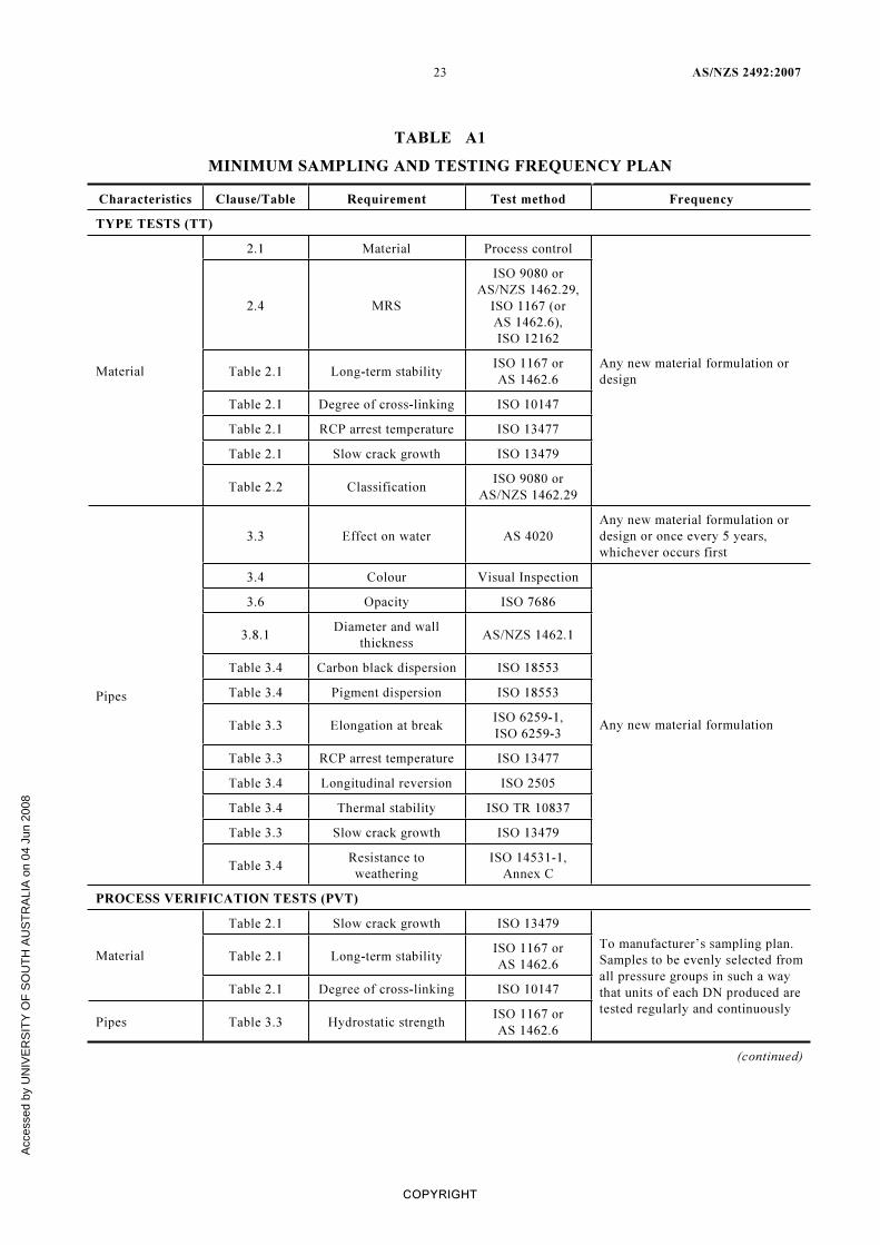
TABLE A1
MINIMUM SAMPLING AND TESTING FREQUENCY PLAN
Characteristics Clause/Table Requirement Test method Frequency
TYPE TESTS (TT)
2.1 Material Process control
2.4 MRS
ISO 9080 or
AS/NZS 1462.29,
ISO 1167 (or
AS 1462.6),
ISO 12162
Table 2.1 Long-term stability
ISO 1167 or
AS 1462.6
Table 2.1 Degree of cross-linking ISO 10147
Table 2.1 RCP arrest temperature ISO 13477
Table 2.1 Slow crack growth ISO 13479
Material
Table 2.2 Classification
ISO 9080 or
AS/NZS 1462.29
Any new material formulation or
design
3.3 Effect on water AS 4020
Any new material formulation or
design or once every 5 years,
whichever occurs first
3.4 Colour Visual Inspection
3.6 Opacity ISO 7686
3.8.1
Diameter and wall
thickness
AS/NZS 1462.1
Table 3.4 Carbon black dispersion ISO 18553
Table 3.4 Pigment dispersion ISO 18553
Table 3.3 Elongation at break
ISO 6259-1,
ISO 6259-3
Table 3.3 RCP arrest temperature ISO 13477
Table 3.4 Longitudinal reversion ISO 2505
Table 3.4 Thermal stability ISO TR 10837
Table 3.3 Slow crack growth ISO 13479
Pipes
Table 3.4
Resistance to
weathering
ISO 14531-1,
Annex C
Any new material formulation
PROCESS VERIFICATION TESTS (PVT)
Table 2.1 Slow crack growth ISO 13479
Table 2.1 Long-term stability
ISO 1167 or
AS 1462.6
Material
Table 2.1 Degree of cross-linking ISO 10147
Pipes Table 3.3 Hydrostatic strength
ISO 1167 or
AS 1462.6
To manufacturer’s sampling plan.
Samples to be evenly selected from
all pressure groups in such a way
that units of each DN produced are
tested regularly and continuously
(continued)
Acc
esse
d by
UN
IVE
RS
ITY
OF
SO
UT
H A
US
TR
ALI
A o
n 04
Jun
200
8

AS/NZS 2492:2007 24
COPYRIGHT
Characteristics Clause/Table Requirement Test method Frequency
BATCH RELEASE TESTS (BRT)
Table 3.4 Pigment dispersion ISO 18553
Table 3.4 Carbon black dispersion ISO 18553
One per batch of compound, or one
per 4 h where pigment or carbon
black masterbatch is added
Table 3.4 Degree of cross-linking ISO 10147
One per 24 h per machine where
pigment or carbon black
masterbatch is added
Table 3.3
Hydrostatic strength at
165 h
Hydrostatic strength at
1 h
ISO 1167 or
AS 1462.6
Table 3.4 Longitudinal reversion ISO 2505
One per week per machine or one
per batch, whichever is the lesser
pipe quantity
Table 3.4 Thermal stability ISO TR 10837 One per batch
3.1 Freedom from defects Visual Inspection One per 4 h
3.4 Colour
Compare pipe
colour to reference
samples of
specified colour
limits by visual
inspection
One per batch of compound
3.8.1
Diameter and wall
thickness
AS 1462.1
One per hour, or start and end of
coil
3.8.2 Coiled pipe ID Visual inspection One per 4 h
Pipes
3.8.3 and
Tables 3.1(A),
3.1(B) and
3.1(C)
Out of roundness AS/NZS 1462.1* One per 4 h
Marking 1.6 Marking Visual Inspection One per 4 h
* May also be tested by attributes (e.g., go and no-go gauges)
TABLE A1 (continued)
Acc
esse
d by
UN
IVE
RS
ITY
OF
SO
UT
H A
US
TR
ALI
A o
n 04
Jun
200
8

25 AS/NZS 2492:2007
COPYRIGHT
APPENDIX B
OPERATING CONDITIONS FOR PE-X 80 PIPES USED FOR CONVEYANCE OF
HOT AND COLD WATER WITHIN BUILDINGS
(Informative)
This Appendix provides data derived from ISO 15875 in order to facilitate selection of
appropriate pipe for the application.
For continuous service temperature of 20°C, design stress is 7.6 Mpa; for 60°C, design
stress is 4.75 Mpa; and for 70°C, design stress is 4.26 MPa.
For continuous service temperatures in excess of 70°C, life beyond 50 years should not be
assumed; however, brief excursions to temperatures up to 100°C may be permissible.
For example, ISO 15875-1 provides for 49 years at 70°C, plus one year at 80°C, plus 100 h
at 95°C.
For particular circumstances, reference should be made to the manufacturer.
A design based on the maximum operating temperature is regarded as conservative and an
advantage may be gained from an analysis that incorporates Miner’s Rule (ISO 13760).
TABLE B1
DATA FOR PIPE SELECTION
Working pressure (MPa)
Continuous
service
temperature
°C
SDR 7.4 SDR 9 SDR 11 SDR 13.6 SDR 17
20
60
70
2.00
1.50
1.33
1.60
1.19
1.09
1.25
0.95
0.88
1.00
0.75
0.69
0.80
0.59
0.54
Acc
esse
d by
UN
IVE
RS
ITY
OF
SO
UT
H A
US
TR
ALI
A o
n 04
Jun
200
8

AS/NZS 2492:2007 26
COPYRIGHT
APPENDIX C
REFERENCED DOCUMENTS
(Informative)
AS
1199 Sampling procedures for inspection by attributes
1199.1 Sampling schemes indexed by acceptance quality limit (AQL) for lot-by-lot
inspection
AS/NZS
1462 Methods of test for plastics pipes and fittings
1462.1 Method 1: Method for determining the dimensions of pipes and fittings
1462.6 Method 6: Method for hydrostatic pressure testing of pipes
1462.27 Method 27: Determination of toluene extract of carbon black
1462.29 Method 29: Plastics piping and ducting systems—Determination of the long-
term hydrostatic strength of thermoplastics materials in pipe form by
extrapolation (ISO 9080:2003, MOD)
3500 Plumbing and drainage
3500.0 Part 0: Glossary of terms
4020 Testing of products for use in contact with drinking water
4129 Fittings for polyethylene (PE) pipes for pressure applications
ISO
3 Preferred numbers—Series of preferred numbers
497 Guide to the choice of series of preferred numbers and of series containing
more rounded values of preferred numbers
1167 Thermoplastics pipes for the conveyance of fluids—Resistance to internal test
pressure—Test Method
2505 Thermoplastic pipes—Longitudinal reversion—Test method and parameters
4065 Thermoplastic pipes—Universal wall thickness table
6259 Thermoplastics pipes—Determination of tensile properties
6259-1 Part 1: General test method
6259-3 Part 3: Polyolefin pipes
6964 Polyolefin pipes and fittings—Determination of carbon black content by
calcination and pyrolysis—Test method and basic specification
7686 Plastics pipes and fittings—Determination of opacity
9080 Plastics piping and ducting systems—Determination of the long-term
hydrostatic strength of thermoplastics materials in pipe form by extrapolation
10147 Pipes and fittings made from crosslinked polyethylene (PE-X)—Estimation of
the degree of crosslinking by determination of the gel content
12162 Thermoplastics materials for pipes and fittings for pressure applications—
Classification and designation—Overall service (design) coefficient
Acc
esse
d by
UN
IVE
RS
ITY
OF
SO
UT
H A
US
TR
ALI
A o
n 04
Jun
200
8
27 AS/NZS 2492:2007
COPYRIGHT
ISO
13477 Thermoplastics pipes for the conveyance of fluids—Determination of resistance
to rapid crack propagation (RCP)—Small-scale steady-state test (S4 test)
13478 Thermoplastics pipes for the conveyance of fluids—Determination of resistance
to rapid crack propagation (RCP)—Full scale test
13479 Polyolefin pipes for the conveyance of fluids—Determination of resistance to
crack propagation—Test method for slow crack growth on notched pipes (notch
test)
13760 Plastics pipes for the conveyance of fluids under pressure—Miner’s rule—
Calculation method for cumulative damage
13954 Plastics pipes and fittings—Peel decohesion test for polyethylene (PE)
electrofusion assemblies of nominal outside diameter greater than or equal to
90 mm
14531 Plastics pipes and fittings—Crosslinked polyethylene (PE-X) pipe systems for
the conveyance of gaseous fuels—Metric series—Specifications
14531-1 Part 1: Pipes
14531-2 Part 2: Fittings for heat-fusion jointing
15875 Plastics piping systems for hot and cold water installations—Crosslinked
polyethylene (PE-X)
15875-1 Part 1: General
18553 Method for the assessment of the degree of pigment or carbon black dispersion
in polyolefin pipes, fittings and compounds
TR 10837 Determination of the thermal stability of polyethylene (PE) for use in gas pipes
and fittings
SA/SANZ
HB 18 Conformity assessment
HB 18.28 Guide 28: Guidance on third-party certification system, for products
ASTM
D3849 Standard test method for carbon black—Morphological characterization of
carbon black using electron microscopy
Acc
esse
d by
UN
IVE
RS
ITY
OF
SO
UT
H A
US
TR
ALI
A o
n 04
Jun
200
8

AS/NZS 2492:2007 28
NOTES
Acc
esse
d by
UN
IVE
RS
ITY
OF
SO
UT
H A
US
TR
ALI
A o
n 04
Jun
200
8

Standards Australia
Standards Australia is an independent company, limited by guarantee, which prepares and publishes
most of the voluntary technical and commercial standards used in Australia. These standards are
developed through an open process of consultation and consensus, in which all interested parties are
invited to participate. Through a Memorandum of Understanding with the Commonwealth
government, Standards Australia is recognized as Australia’s peak national standards body.
Standards New Zealand
The first national Standards organization was created in New Zealand in 1932. The Standards
Council of New Zealand is the national authority responsible for the production of Standards.
Standards New Zealand is the trading arm of the Standards Council established under the Standards
Act 1988.
Australian/New Zealand Standards
Under a Memorandum of Understanding between Standards Australia and Standards New Zealand,
Australian/New Zealand Standards are prepared by committees of experts from industry,
governments, consumers and other sectors. The requirements or recommendations contained
in published Standards are a consensus of the views of representative interests and also take
account of comments received from other sources. They reflect the latest scientific and industry
experience. Australian/New Zealand Standards are kept under continuous review after publication
and are updated regularly to take account of changing technology.
International Involvement
Standards Australia and Standards New Zealand are responsible for ensuring that the Australian
and New Zealand viewpoints are considered in the formulation of international Standards and that
the latest international experience is incorporated in national and Joint Standards. This role is vital
in assisting local industry to compete in international markets. Both organizations are the national
members of ISO (the International Organization for Standardization) and IEC (the International
Electrotechnical Commission).
Visit our web sites
www.standards.org.au www.standards.co.nz
www.standards.com.au
Acc
esse
d by
UN
IVE
RS
ITY
OF
SO
UT
H A
US
TR
ALI
A o
n 04
Jun
200
8
GPO Box 476 Sydney NSW 2001
Administration
Phone (02) 9237 6000
Fax (02) 9237 6010
Email [email protected]
Customer Service
Phone 1300 65 46 46
Fax 1300 65 49 49
Email [email protected]
Internet www.standards.org.au
Level 10 Radio New Zealand House
155 The Terrace Wellington 6001
(Private Bag 2439 Wellington 6020)
Phone (04) 498 5990
Fax (04) 498 5994
Customer Services (04) 498 5991
Information Service (04) 498 5992
Email [email protected]
Internet www.standards.co.nz
ISBN 0 7337 8289 2 Printed in Australia
Acc
esse
d by
UN
IVE
RS
ITY
OF
SO
UT
H A
US
TR
ALI
A o
n 04
Jun
200
8

This page has been left intentionally blank.
Acc
esse
d by
UN
IVE
RS
ITY
OF
SO
UT
H A
US
TR
ALI
A o
n 04
Jun
200
8


