32
Translation of the original manual Assembly- and Operating Manual SKE Swivel Unit

Translation of the original manual
Assembly- and Operating ManualSKESwivel Unit

Imprint
2 06.00 | SKE | Assembly- and Operating Manual | en | 389407
ImprintCopyright:This manual is protected by copyright. The author is SCHUNK GmbH & Co. KG. All rightsreserved.
Technical changes:We reserve the right to make alterations for the purpose of technical improvement.
Document number: 389407
Version: 06.00 | 23/02/2021 | en
Dear Customer,thank you for trusting our products and our family-owned company, the leadingtechnology supplier of robots and production machines.Our team is always available to answer any questions on this product and other solutions.Ask us questions and challenge us. We will find a solution!Best regards,Your SCHUNK team
Customer ManagementTel. +49-7133-103-2500Fax [email protected]
Please read the operating manual in full and keep it close to the product.

Table of Contents
Table of Contents1 General.................................................................................................................... 4
1.1 About this manual ................................................................................................ 41.1.1 Presentation of Warning Labels ............................................................... 41.1.2 Applicable documents .............................................................................. 5
1.2 Warranty .............................................................................................................. 51.3 Scope of delivery .................................................................................................. 51.4 Accessories ........................................................................................................... 5
1.4.1 Sensors ..................................................................................................... 52 Basic safety notes ................................................................................................... 6
2.1 Intended use......................................................................................................... 62.2 Not intended use.................................................................................................. 62.3 Constructional changes ........................................................................................ 62.4 Spare parts ........................................................................................................... 62.5 Ambient conditions and operating conditions ..................................................... 72.6 Personnel qualification......................................................................................... 72.7 Personal protective equipment............................................................................ 82.8 Notes on safe operation ....................................................................................... 82.9 Transport .............................................................................................................. 82.10 Malfunctions......................................................................................................... 92.11 Disposal ................................................................................................................ 92.12 Fundamental dangers........................................................................................... 9
2.12.1 Protection during handling and assembly .............................................. 102.12.2 Protection during commissioning and operation ................................... 102.12.3 Protection against dangerous movements............................................. 112.12.4 Protection against electric shock............................................................ 11
2.13 Notes on particular risks..................................................................................... 123 Technical Data ....................................................................................................... 134 Assembly ................................................................................................................ 14
4.1 Connections........................................................................................................ 144.1.1 Mechanical connection........................................................................... 144.1.2 Pneumatic connection............................................................................ 15
4.2 Gripper assembly................................................................................................ 174.3 Other grippers .................................................................................................... 184.4 Mounting the sensor .......................................................................................... 19
4.4.1 Inductive proximity switch IN 40 ............................................................ 204.4.2 Inductive proximity switch IN 80 ............................................................ 22
5 Maintenance and care ............................................................................................ 256 Translation of original declaration of incorporation ................................................ 26
6.1 Annex to Declaration of Incorporation............................................................... 27
306.00 | SKE | Assembly- and Operating Manual | en | 389407

General
4 06.00 | SKE | Assembly- and Operating Manual | en | 389407
1 General1.1 About this manual
This manual contains important information for a safe andappropriate use of the product.This manual is an integral part of the product and must be keptaccessible for the personnel at all times.Before starting work, the personnel must have read andunderstood this operating manual. Prerequisite for safe working isthe observance of all safety instructions in this manual.Illustrations in this manual are provided for basic understandingand may differ from the actual product design.In addition to these instructions, the documents listed underApplicable documents [} 5] are applicable.
1.1.1 Presentation of Warning Labels
To make risks clear, the following signal words and symbols areused for safety notes.
DANGERDanger for persons!Non-observance will inevitably cause irreversible injury or death.
WARNINGDangers for persons!Non-observance can lead to irreversible injury and even death.
CAUTIONDangers for persons!Non-observance can cause minor injuries.
CAUTIONMaterial damage!Information about avoiding material damage.
General
1.1.2 Applicable documents
• General terms of business *• Catalog data sheet of the purchased product *• Assembly and operating manuals of the accessories *The documents marked with an asterisk (*) can be downloaded onour homepage schunk.com
1.2 WarrantyIf the product is used as intended, the warranty is valid for 24months from the ex-works delivery date under the followingconditions:• Observe the specified maintenance and lubrication intervals• Observe the ambient conditions and operating conditionsParts touching the workpiece and wear parts are not included inthe warranty.
1.3 Scope of deliveryThe scope of delivery includes• Swivel Unit SKE in the version ordered• 2 One-way restrictors• Brackets for proximity switches
1.4 AccessoriesA wide range of accessories are available for this productFor information regarding which accessory articles can be usedwith the corresponding product variants, see catalog data sheet.
1.4.1 SensorsOverview of the compatible sensors
Designation TypeInductive proximity switches IN
• Exact type designation of the compatible sensors see catalog.• Information on handling sensors is available at schunk.com or
from SCHUNK contact persons.
506.00 | SKE | Assembly- and Operating Manual | en | 389407

Basic safety notes
6 06.00 | SKE | Assembly- and Operating Manual | en | 389407
2 Basic safety notes2.1 Intended use
The product may only be used for swiveling permissibleattachment parts or workpieces.• The product may only be used within the scope of its technical
data, Technical Data [} 13].• When implementing and operating components in safety-
related parts of the control systems, the basic safety principlesin accordance with DIN EN ISO 13849-2 apply. The proven safetyprinciples in accordance with DIN EN ISO 13849-2 also apply tocategories 1, 2, 3 and 4.
• The product is intended for installation in a machine/system.The applicable guidelines must be observed and complied with.
• The product is intended for industrial and industry-oriented use.• Appropriate use of the product includes compliance with all
instructions in this manual.
2.2 Not intended useIt is not intended use if the product is used, for example, as apressing tool, stamping tool, lifting gear, guide for tools, cuttingtool, clamping device or a drilling tool.• Any utilization that exceeds or differs from the appropriate use
is regarded as misuse.
2.3 Constructional changesImplementation of structural changesBy conversions, changes, and reworking, e.g. additional threads,holes, or safety devices can impair the functioning or safety of theproduct or damage it.• Structural changes should only be made with the written
approval of SCHUNK.
2.4 Spare partsUse of unauthorized spare partsUsing unauthorized spare parts can endanger personnel anddamage the product or cause it to malfunction.• Use only original spare parts or spares authorized by SCHUNK.

Basic safety notes
2.5 Ambient conditions and operating conditionsRequired ambient conditions and operating conditionsIncorrect ambient and operating conditions can make the productunsafe, leading to the risk of serious injuries, considerable materialdamage and/or a significant reduction to the product's life span.• Make sure that the product is used only in the context of its
defined application parameters, Technical Data [} 13].
2.6 Personnel qualificationInadequate qualifications of the personnelIf the personnel working with the product is not sufficientlyqualified, the result may be serious injuries and significantproperty damage.• All work may only be performed by qualified personnel.• Before working with the product, the personnel must have read
and understood the complete assembly and operating manual.• Observe the national safety regulations and rules and general
safety instructions.The following personal qualifications are necessary for the variousactivities related to the product:
Trained electrician Due to their technical training, knowledge and experience, trainedelectricians are able to work on electrical systems, recognize andavoid possible dangers and know the relevant standards andregulations.
Qualified personnel Due to its technical training, knowledge and experience, qualifiedpersonnel is able to perform the delegated tasks, recognize andavoid possible dangers and knows the relevant standards andregulations.
Instructed person Instructed persons were instructed by the operator about thedelegated tasks and possible dangers due to improper behaviour.
Service personnel ofthe manufacturer
Due to its technical training, knowledge and experience, servicepersonnel of the manufacturer is able to perform the delegatedtasks and to recognize and avoid possible dangers.
706.00 | SKE | Assembly- and Operating Manual | en | 389407
Basic safety notes
8 06.00 | SKE | Assembly- and Operating Manual | en | 389407
2.7 Personal protective equipmentUse of personal protective equipmentPersonal protective equipment serves to protect staff againstdanger which may interfere with their health or safety at work.• When working on and with the product, observe the
occupational health and safety regulations and wear therequired personal protective equipment.
• Observe the valid safety and accident prevention regulations.• Wear protective gloves to guard against sharp edges and
corners or rough surfaces.• Wear heat-resistant protective gloves when handling hot
surfaces.• Wear protective gloves and safety goggles when handling
hazardous substances.• Wear close-fitting protective clothing and also wear long hair in
a hairnet when dealing with moving components.
2.8 Notes on safe operationIncorrect handling of the personnelIncorrect handling and assembly may impair the product's safetyand cause serious injuries and considerable material damage.• Avoid any manner of working that may interfere with the
function and operational safety of the product.• Use the product as intended.• Observe the safety notes and assembly instructions.• Do not expose the product to any corrosive media. This does
not apply to products that are designed for specialenvironments.
• Eliminate any malfunction immediately.• Observe the care and maintenance instructions.• Observe the current safety, accident prevention and
environmental protection regulations regarding the product'sapplication field.
2.9 TransportHandling during transportIncorrect handling during transport may impair the product'ssafety and cause serious injuries and considerable materialdamage.• When handling heavy weights, use lifting equipment to lift the
product and transport it by appropriate means.• Secure the product against falling during transportation and
handling.• Stand clear of suspended loads.
Basic safety notes
2.10 MalfunctionsBehavior in case of malfunctions• Immediately remove the product from operation and report the
malfunction to the responsible departments/persons.• Order appropriately trained personnel to rectify the
malfunction.• Do not recommission the product until the malfunction has
been rectified.• Test the product after a malfunction to establish whether it still
functions properly and no increased risks have arisen.
2.11 DisposalHandling of disposalThe incorrect handling of disposal may impair the product's safetyand cause serious injuries as well as considerable material andenvironmental harm.• Follow local regulations on dispatching product components for
recycling or proper disposal.
2.12 Fundamental dangersGeneral• Observe safety distances.• Never deactivate safety devices.• Before commissioning the product, take appropriate protective
measures to secure the danger zone.• Disconnect power sources before installation, modification,
maintenance, or calibration. Ensure that no residual energyremains in the system.
• If the energy supply is connected, do not move any parts byhand.
• Do not reach into the open mechanism or movement area ofthe product during operation.
906.00 | SKE | Assembly- and Operating Manual | en | 389407
Basic safety notes
10 06.00 | SKE | Assembly- and Operating Manual | en | 389407
2.12.1 Protection during handling and assembly
Incorrect handling and assemblyIncorrect handling and assembly may impair the product's safetyand cause serious injuries and considerable material damage.• Have all work carried out by appropriately qualified personnel.• For all work, secure the product against accidental operation.• Observe the relevant accident prevention rules.• Use suitable assembly and transport equipment and take
precautions to prevent jamming and crushing.Incorrect lifting of loadsFalling loads may cause serious injuries and even death.• Stand clear of suspended loads and do not step into their
swiveling range.• Never move loads without supervision.• Do not leave suspended loads unattended.
2.12.2 Protection during commissioning and operation
Falling or violently ejected componentsFalling and violently ejected components can cause serious injuriesand even death.• Take appropriate protective measures to secure the danger
zone.• Never step into the danger zone during operation.

Basic safety notes
2.12.3 Protection against dangerous movements
Unexpected movementsResidual energy in the system may cause serious injuries whileworking with the product.• Switch off the energy supply, ensure that no residual energy
remains and secure against inadvertent reactivation.• Never rely solely on the response of the monitoring function to
avert danger. Until the installed monitors become effective, itmust be assumed that the drive movement is faulty, with itsaction being dependent on the control unit and the currentoperating condition of the drive. Perform maintenance work,modifications, and attachments outside the danger zonedefined by the movement range.
• To avoid accidents and/or material damage, human access tothe movement range of the machine must be restricted. Limit/prevent accidental access for people in this area due throughtechnical safety measures. The protective cover and protectivefence must be rigid enough to withstand the maximum possiblemovement energy. EMERGENCY STOP switches must be easilyand quickly accessible. Before starting up the machine orautomated system, check that the EMERGENCY STOP system isworking. Prevent operation of the machine if this protectiveequipment does not function correctly.
2.12.4 Protection against electric shock
Possible electrostatic energyComponents or assembly groups may become electrostaticallycharged. When the electrostatic charge is touched, the dischargemay trigger a shock reaction leading to injuries.• The operator must ensure that all components and assembly
groups are included in the local potential equalisation inaccordance with the applicable regulations.
• While paying attention to the actual conditions of the workingenvironment, the potential equalisation must be implementedby a specialist electrician according to the applicableregulations.
• The effectiveness of the potential equalisation must be verifiedby executing regular safety measurements.
1106.00 | SKE | Assembly- and Operating Manual | en | 389407

Basic safety notes
12 06.00 | SKE | Assembly- and Operating Manual | en | 389407
2.13 Notes on particular risks
DANGERRisk of fatal injury from suspended loads!Falling loads can cause serious injuries and even death.• Stand clear of suspended loads and do not step within their
swiveling range.• Never move loads without supervision.• Do not leave suspended loads unattended.• Wear suitable protective equipment.
WARNINGRisk of injury from objects falling and being ejected!Falling and ejected objects during operation can lead to seriousinjury or death.• Take appropriate protective measures to secure the danger
zone.
WARNINGRisk of injury due to unexpected movements!If the power supply is switched on or residual energy remains inthe system, components can move unexpectedly and causeserious injuries.• Before starting any work on the product: Switch off the power
supply and secure against restarting.• Make sure, that no residual energy remains in the system.
WARNINGRisk of injury from sharp edges and corners!Sharp edges and corners can cause cuts.• Use suitable protective equipment.

Technical Data
3 Technical Data
SKE 18 SKE 22 SKE 40 SKE 55Torque [Nm] 0.4 0.75 5.0 9.0Angle of rotation [°] 90.0End position adjustability[°] 5.0IP rating 30Weight [kg] 0.13 0.2 0.92 1.95Cycle time (1 x nominal angle ofrotation) without attached load [s]
0.5 0.8 1.0 1.5
Air consumption per cycle (2 x nominal angle) [cm3]
10.0 20.0 100.0 160.0
Nominal working pressure [bar] 4.0Min. pressure [bar] 1.0Max. pressure [bar] 6.0Diameter hose connection [mm] 4.0Min. ambient temperature [°C] 5.0Max. ambient temperature [°C] 50.0Repeatability [mm] 0.03Noise emission [dB(A)] ≤ 70
More technical data is included in the catalog data sheet.Whichever is the latest version.
1306.00 | SKE | Assembly- and Operating Manual | en | 389407
Assembly
14 06.00 | SKE | Assembly- and Operating Manual | en | 389407
4 Assembly4.1 Connections
4.1.1 Mechanical connection
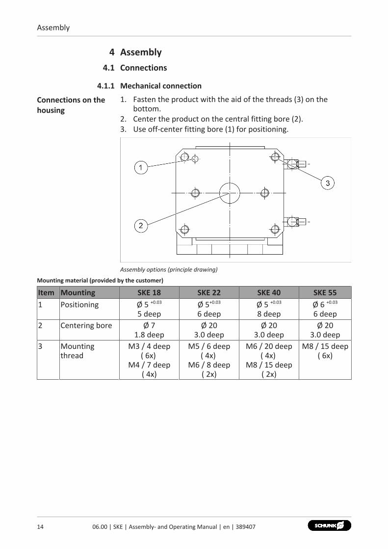
Connections on thehousing
1. Fasten the product with the aid of the threads (3) on thebottom.
2. Center the product on the central fitting bore (2).3. Use off-center fitting bore (1) for positioning.
Assembly options (principle drawing)
Mounting material (provided by the customer)
Item Mounting SKE 18 SKE 22 SKE 40 SKE 551 Positioning Ø 5 +0.03
5 deepØ 5+0.03
6 deepØ 5 +0.03
8 deepØ 6 +0.03
6 deep2 Centering bore Ø 7
1.8 deepØ 20
3.0 deepØ 20
3.0 deepØ 20
3.0 deep3 Mounting
threadM3 / 4 deep
( 6x) M4 / 7 deep
( 4x)
M5 / 6 deep( 4x)
M6 / 8 deep( 2x)
M6 / 20 deep( 4x)
M8 / 15 deep( 2x)
M8 / 15 deep( 6x)

Assembly
4.1.2 Pneumatic connection
WARNINGRisk of injury due to moving parts!Rotating components and/or components moving linearly maycause severe injuries.• Do not interfere with moving parts during operation.• Wear protective equipment.
NOTE• Observe the requirements for the compressed air supply,
Technical Data [} 13].• In case of compressed air loss (cutting off the energy line), the
components lose their dynamic effects and do not remain in asecure position. However, the use of a SDV-P pressuremaintenance valve is recommended in this case in order tomaintain the dynamic effect for some time. Product variantsare also offered with mechanical gripping force via springs,which also ensure a minimum clamping force in the event of apressure drop.
NOTEThe air connections are equipped with one-way flow controlvalves.The optimal swiveling speed is achieved by adjusting the swivelingtime on the exhaust air throttles.Fine adjustment must be carried out on the fully assembledsystem. Never operate the swivel unit without the one-way flowcontrol valves mounted. Do not go below the specified swivelingtime.
CAUTIONMaterial damage due to too high swiveling speed!If the swiveling speed is too high, the assembly will bedecelerated abruptly by the shock absorber and will continue tooscillate until reaching the end position. This will overload theshock absorber and may cause damage to it.• Adjust the swiveling speed in a way, that the movement
decelerate smoothly in the end position.
1506.00 | SKE | Assembly- and Operating Manual | en | 389407
Assembly
16 06.00 | SKE | Assembly- and Operating Manual | en | 389407
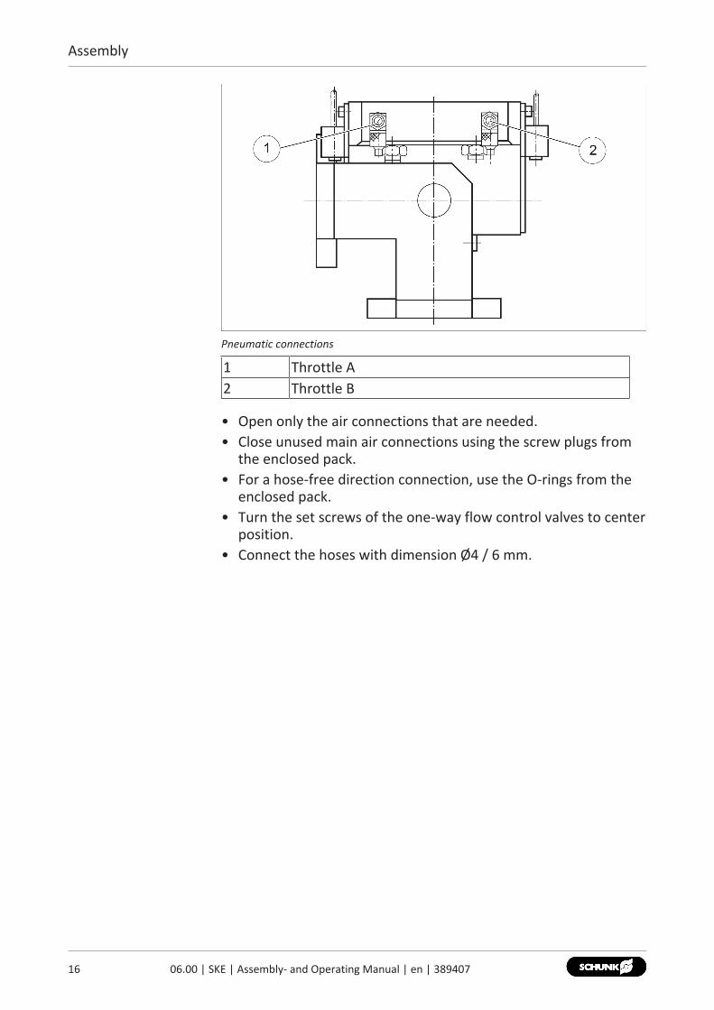
Pneumatic connections
1 Throttle A2 Throttle B
• Open only the air connections that are needed.• Close unused main air connections using the screw plugs from
the enclosed pack.• For a hose-free direction connection, use the O-rings from the
enclosed pack.• Turn the set screws of the one-way flow control valves to center
position.• Connect the hoses with dimension Ø4 / 6 mm.

Assembly
4.2 Gripper assemblyOne or two grippers can be mounted on the swivel unit (1).1. Remove the adapter plates (2) to facilitate installation.2. Fasten gripper(s) to adapter plates (2) with screws.
IMPORTANT! Make sure that the screw heads do notprotrude. Note: The grippers can be mounted centrally on theadapter plate either parallel or vertical to the swivel axis.✓ Observe the tightening torque.
3. Fasten the adapter plates (2) with screws (3).✓ Observe the tightening torque.
Gripper fasteningscrew dimension
Usable grippers and dimensions of fastening screws
Type Gripper type/fastening screw dimension (DIN EN ISO 4762)
SKE 18 RHL 0 / M3 RH 901 / M3 RH 901 ST 10 /M3
SKE 22 RH 801 / M3 RH 905 / M4 RH 907 / M4SKE 40 RH 806 KP / M4 RH 925 / M5 -SKE 55 RH 940 / M6 - -
Tightening torque Tightening torque, fastening screws, gripper/adapter plate
Type Fastening screwdimensionDIN EN ISO 4762, 10.9
Tightening torque [Nm]
SKE 18 M2.5 0.9SKE 22 M3 1.6SKE 40 M4 3.8SKE 55 M5 7.5
1706.00 | SKE | Assembly- and Operating Manual | en | 389407
Assembly
18 06.00 | SKE | Assembly- and Operating Manual | en | 389407
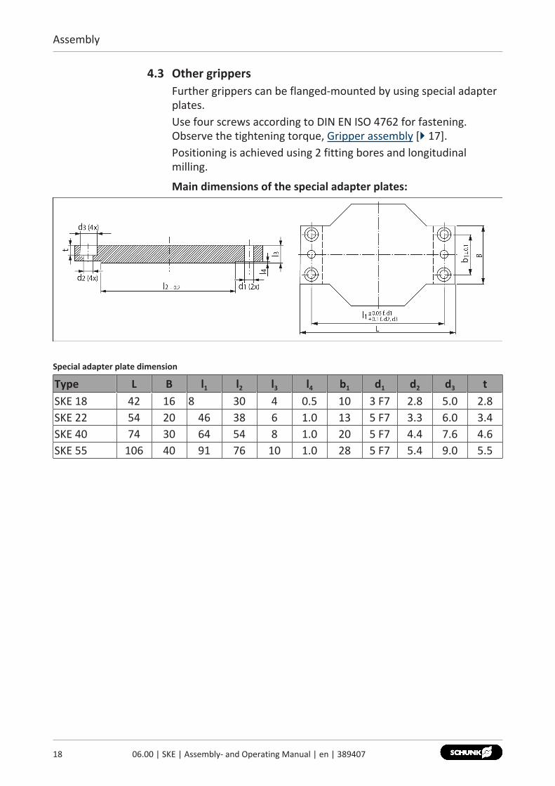
4.3 Other grippersFurther grippers can be flanged-mounted by using special adapterplates.Use four screws according to DIN EN ISO 4762 for fastening.Observe the tightening torque, Gripper assembly [} 17].Positioning is achieved using 2 fitting bores and longitudinalmilling.
Main dimensions of the special adapter plates:
Special adapter plate dimension
Type L B l1 l2 l3 l4 b1 d1 d2 d3 tSKE 18 42 16 8 30 4 0.5 10 3 F7 2.8 5.0 2.8SKE 22 54 20 46 38 6 1.0 13 5 F7 3.3 6.0 3.4SKE 40 74 30 64 54 8 1.0 20 5 F7 4.4 7.6 4.6SKE 55 106 40 91 76 10 1.0 28 5 F7 5.4 9.0 5.5

Assembly
4.4 Mounting the sensor
NOTEObserve the assembly and operating manual of the sensor formounting and connecting.
The product is equipped for the use of sensors.• For the exact type designations of suitable sensors, please see
the catalog data sheet.• For technical data for the suitable sensors, see Assembly and
Operating Manual and catalog data sheet.– The Assembly and Operating Manual and catalog data sheet
are included in the scope of delivery for the sensors and areavailable at schunk.com.
• Information on handling sensors is available at schunk.com orfrom SCHUNK contact persons.
1906.00 | SKE | Assembly- and Operating Manual | en | 389407
Assembly
20 06.00 | SKE | Assembly- and Operating Manual | en | 389407
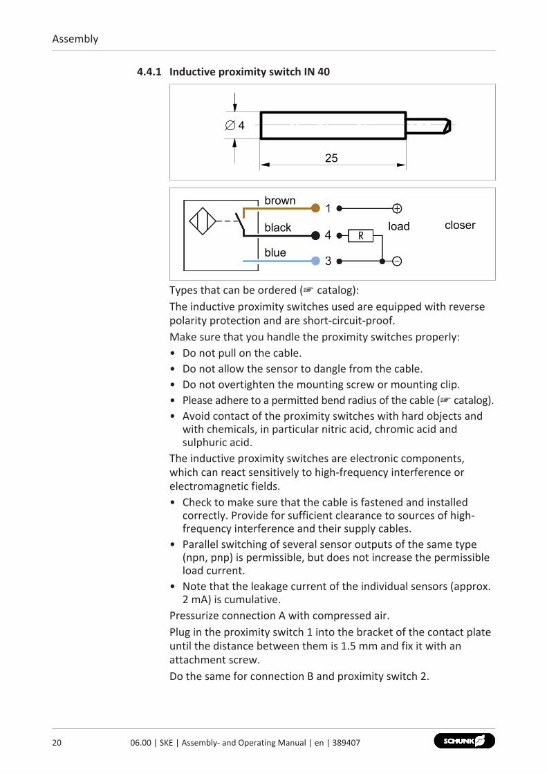
4.4.1 Inductive proximity switch IN 40
4
25
brown
black
blue
load closer
Types that can be ordered (☞ catalog):The inductive proximity switches used are equipped with reversepolarity protection and are short-circuit-proof.Make sure that you handle the proximity switches properly:• Do not pull on the cable.• Do not allow the sensor to dangle from the cable.• Do not overtighten the mounting screw or mounting clip.• Please adhere to a permitted bend radius of the cable (☞ catalog).• Avoid contact of the proximity switches with hard objects and
with chemicals, in particular nitric acid, chromic acid andsulphuric acid.
The inductive proximity switches are electronic components,which can react sensitively to high-frequency interference orelectromagnetic fields.• Check to make sure that the cable is fastened and installed
correctly. Provide for sufficient clearance to sources of high-frequency interference and their supply cables.
• Parallel switching of several sensor outputs of the same type(npn, pnp) is permissible, but does not increase the permissibleload current.
• Note that the leakage current of the individual sensors (approx.2 mA) is cumulative.
Pressurize connection A with compressed air.Plug in the proximity switch 1 into the bracket of the contact plateuntil the distance between them is 1.5 mm and fix it with anattachment screw.Do the same for connection B and proximity switch 2.

Assembly
Proximity switch forSKE 18
Proximity switch for SKE 18
1 Bracket2 Attachment screw (DIN 912 M2.5 x 6)3 Contact plate4 Proximity switch 25 Proximity switch 16 Connection A7 Connection B
2106.00 | SKE | Assembly- and Operating Manual | en | 389407
Assembly
22 06.00 | SKE | Assembly- and Operating Manual | en | 389407
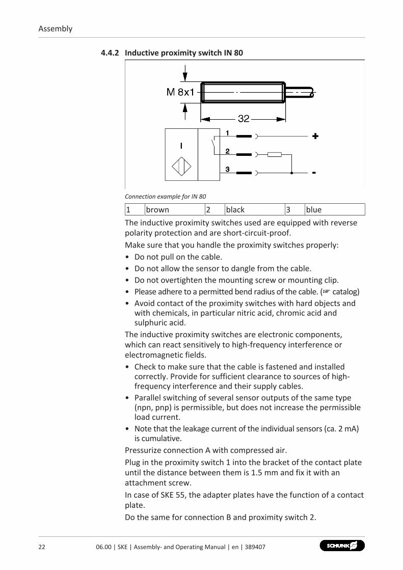
4.4.2 Inductive proximity switch IN 80
Connection example for IN 80
1 brown 2 black 3 blueThe inductive proximity switches used are equipped with reversepolarity protection and are short-circuit-proof.Make sure that you handle the proximity switches properly:• Do not pull on the cable.• Do not allow the sensor to dangle from the cable.• Do not overtighten the mounting screw or mounting clip.• Please adhere to a permitted bend radius of the cable. (☞ catalog)• Avoid contact of the proximity switches with hard objects and
with chemicals, in particular nitric acid, chromic acid andsulphuric acid.
The inductive proximity switches are electronic components,which can react sensitively to high-frequency interference orelectromagnetic fields.• Check to make sure that the cable is fastened and installed
correctly. Provide for sufficient clearance to sources of high-frequency interference and their supply cables.
• Parallel switching of several sensor outputs of the same type(npn, pnp) is permissible, but does not increase the permissibleload current.
• Note that the leakage current of the individual sensors (ca. 2 mA)is cumulative.
Pressurize connection A with compressed air.Plug in the proximity switch 1 into the bracket of the contact plateuntil the distance between them is 1.5 mm and fix it with anattachment screw.In case of SKE 55, the adapter plates have the function of a contactplate.Do the same for connection B and proximity switch 2.

Assembly
Proximity switch forSKE 22
Proximity switch for SKE 22
1 Bracket2 Attachment screw (DIN 912 M3 x 8)3 Control cam4 Proximity switch 25 Proximity switch 16 Connection A7 Connection B
Proximity switch forSKE 40
Proximity switch for SKE 40
2306.00 | SKE | Assembly- and Operating Manual | en | 389407
Assembly
24 06.00 | SKE | Assembly- and Operating Manual | en | 389407
1 Bracket2 Attachment screw (DIN 912 M3 x 8)3 Contace plate4 Proximity switch 25 Proximity switch 16 Connection A7 Connection B
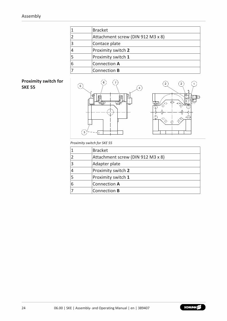
Proximity switch forSKE 55
Proximity switch for SKE 55
1 Bracket2 Attachment screw (DIN 912 M3 x 8)3 Adapter plate4 Proximity switch 25 Proximity switch 16 Connection A7 Connection B

Maintenance and care
5 Maintenance and careThe swivel unit is maintenance-free.If the product gets dirty, wipe it carefully with a soft cloth. Do notuse solvents.
2506.00 | SKE | Assembly- and Operating Manual | en | 389407

Translation of original declaration of incorporation
26 06.00 | SKE | Assembly- and Operating Manual | en | 389407
6 Translation of original declaration of incorporationin terms of the Directive 2006/42/EG, Annex II, Part 1.B of the European Parliament and ofthe Council on machinery.
Manufacturer/Distributor
SCHUNK GmbH & Co. KG Spann- und Greiftechnik Bahnhofstr. 106 – 134 D-74348 Lauffen/Neckar
We hereby declare that on the date of the declaration the following partly completedmachine complied with all basic safety and health regulations found in the directive2006/42/EC of the European Parliament and of the Council on machinery. The declarationis rendered invalid if modifications are made to the product.
Product designation: Swivel Unit / SKE / pneumaticID number 0351100 ... 0351106
The partly completed machine may not be put into operation until conformity of themachine into which the partly completed machine is to be installed with the provisions ofthe Machinery Directive (2006/42/EC) is confirmed.
Applied harmonized standards, especially:
EN ISO 12100:2010 Safety of machinery - General principles for design -Risk assessment and risk reduction
The manufacturer agrees to forward on demand the relevant technical documentation forthe partly completed machinery in electronic form to national authorities.The relevant technical documentation according to Annex VII, Part B, belonging to thepartly completed machinery, has been created.
Person authorized to compile the technical documentation: Robert Leuthner, Address: see manufacturer's address
Lauffen/Neckar, February 2021 p.p. Ralf Winkler; Head of Technology & Engineering,
Mechanics Gripping Systems

Translation of original declaration of incorporation
6.1 Annex to Declaration of Incorporationaccording 2006/42/EG, Annex II, No. 1 B
1.Description of the essential health and safety requirements pursuant to 2006/42/EC,Annex I that are applicable and that have been fulfilled with:
Product designation Swivel UnitType designation SKEID number 0351100 ... 0351106
To be provided by the System Integrator for the overall machine ⇓Fulfilled for the scope of the partly completed machine ⇓
Not relevant ⇓
1.1 Essential Requirements1.1.1 Definitions X1.1.2 Principles of safety integration X1.1.3 Materials and products X1.1.4 Lighting X1.1.5 Design of machinery to facilitate its handling X1.1.6 Ergonomics X1.1.7 Operating positions X1.1.8 Seating X
1.2 Control Systems1.2.1 Safety and reliability of control systems X1.2.2 Control devices X1.2.3 Starting X1.2.4 Stopping X1.2.4.1 Normal stop X1.2.4.2 Operational stop X1.2.4.3 Emergency stop X1.2.4.4 Assembly of machinery X1.2.5 Selection of control or operating modes X1.2.6 Failure of the power supply X
1.3 Protection against mechanical hazards1.3.1 Risk of loss of stability X1.3.2 Risk of break-up during operation X1.3.3 Risks due to falling or ejected objects X1.3.4 Risks due to surfaces, edges or angles X1.3.5 Risks related to combined machinery X1.3.6 Risks related to variations in operating conditions X
2706.00 | SKE | Assembly- and Operating Manual | en | 389407

Translation of original declaration of incorporation
28 06.00 | SKE | Assembly- and Operating Manual | en | 389407
1.3 Protection against mechanical hazards1.3.7 Risks related to moving parts X1.3.8 Choice of protection against risks arising from moving parts X1.3.8.1 Moving transmission parts X1.3.8.2 Moving parts involved in the process X1.3.9 Risks of uncontrolled movements X
1.4 Required characteristics of guards and protective devices1.4.1 General requirements X1.4.2 Special requirements for guards X1.4.2.1 Fixed guards X1.4.2.2 Interlocking movable guards X1.4.2.3 Adjustable guards restricting access X1.4.3 Special requirements for protective devices X
1.5 Risks due to other hazards1.5.1 Electricity supply X1.5.2 Static electricity X1.5.3 Energy supply other than electricity X1.5.4 Errors of fitting X1.5.5 Extreme temperatures X1.5.6 Fire X1.5.7 Explosion X1.5.8 Noise X1.5.9 Vibrations X1.5.10 Radiation X1.5.11 External radiation X1.5.12 Laser radiation X1.5.13 Emissions of hazardous materials and substances X1.5.14 Risk of being trapped in a machine X1.5.15 Risk of slipping, tripping or falling X1.5.16 Lightning X
1.6 Maintenance1.6.1 Machinery maintenance X1.6.2 Access to operating positions and servicing points X1.6.3 Isolation of energy sources X1.6.4 Operator intervention X1.6.5 Cleaning of internal parts X

Translation of original declaration of incorporation
1.7 Information1.7.1 Information and warnings on the machinery X1.7.1.1 Information and information devices X1.7.1.2 Warning devices X1.7.2 Warning of residual risks X1.7.3 Marking of machinery X1.7.4 Instructions X1.7.4.1 General principles for the drafting of instructions X1.7.4.2 Contents of the instructions X1.7.4.3 Sales literature X
The classification from Annex 1 is to be supplemented from hereforward.
2 Supplementary essential health and safety requirements for certaincategories of machinery
X
2.1 Foodstuffs machinery and machinery for cosmetics or pharmaceuticalproducts
X
2.2 Portable hand-held and/or guided machinery X2.2.1 Portable fixing and other impact machinery X2.3 Machinery for working wood and material with similar physical
characteristicsX
3 Supplementary essential health and safety requirements to offsethazards due to the mobility of machinery
X
4 Supplementary essential health and safety requirements to offsethazards due to lifting operations
X
5 Supplementary essential health and safety requirements for machineryintended for underground work
X
6 Supplementary essential health and safety requirements for machinerypresenting particular hazards due to the lifting of persons
X
2906.00 | SKE | Assembly- and Operating Manual | en | 389407


Translation of the original manual
SCHUNK GmbH & Co. KGSpann- und GreiftechnikBahnhofstr. 106 – 134D-74348 Lauffen/NeckarTel. +49-7133-103-0Fax [email protected]
Folgen Sie uns I Follow us02
-202
1
© 2
021
SCHU
NK
GmbH
& C
o. K
G
06.0
0 |
SKE
| As
sem
bly-
and
Ope
ratin
g M
anua
l | e
n |
3894
07


