54
AutoCad Basic Tutorial
| Date post: | 16-Jul-2015 |
| Category: |
Education |
| Upload: | julio-alcaraz-evaristo |
| View: | 908 times |
| Download: | 15 times |
AutoCad Basic Tutorial
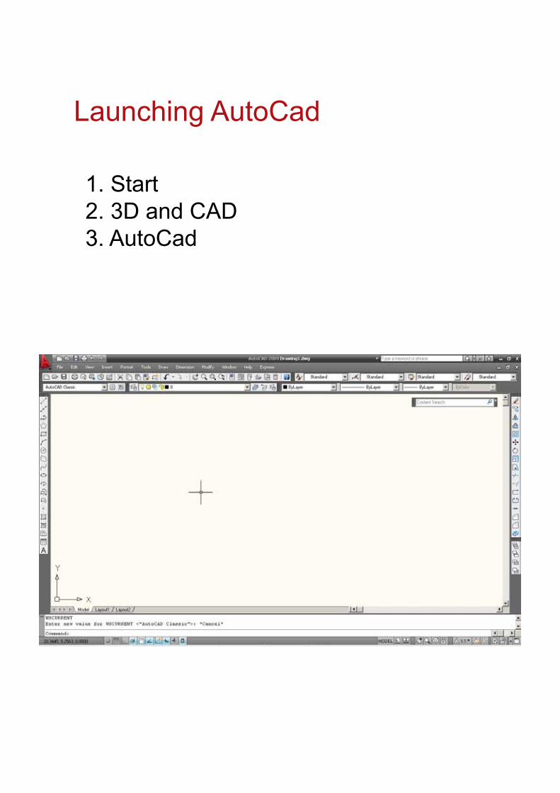
Launching AutoCad
1. Start2. 3D and CAD3. AutoCad
Typing CommandsTyping a Command
All AutoCAD commands can be typed in at the command line. Many commands also have one
or two letter aliases that can also be typed as shortcuts to the commands.
1. Type the desired command at the command prompt.
Command : LINE
or
2. Type the command’s alias. Command: L
3. Press ENTER/Space to end.
4. Type an option at the command prompt.
TIP: Many AutoCAD commands require you to press ENTER to complete the command. You know you are no
longer in an AutoCAD command when you see a blank command line.
Reissuing the Last Command
The last used AutoCAD command can be re-entered by one of the following three methods
of ENTER. The ENTER key on the keyboard will always act as ENTER, the SPACEBAR and
RIGHT MOUSE will act as enter most of the time (exceptions include placing TEXT).
1. Press the ENTER key on the keyboard
or
2. Press the Space bar on the keyboard.
or
3. Click the right mouse button.
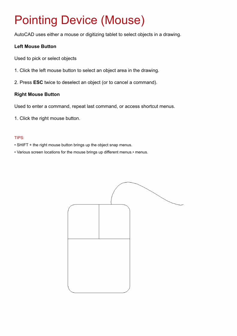
Pointing Device (Mouse)AutoCAD uses either a mouse or digitizing tablet to select objects in a drawing.
Left Mouse Button
Used to pick or select objects
1. Click the left mouse button to select an object area in the drawing.
2. Press ESC twice to deselect an object (or to cancel a command).
Right Mouse Button
Used to enter a command, repeat last command, or access shortcut menus.
1. Click the right mouse button.
TIPS:
• SHIFT + the right mouse button brings up the object snap menus.
• Various screen locations for the mouse brings up different menus.• menus.
5.2 PAN
Shifts the location of a view.
1. Choose View, Pan.
or
2. Click the Pan icon.
or
3. Type PAN from the command prompt.
Command: PAN or P
TIPS:
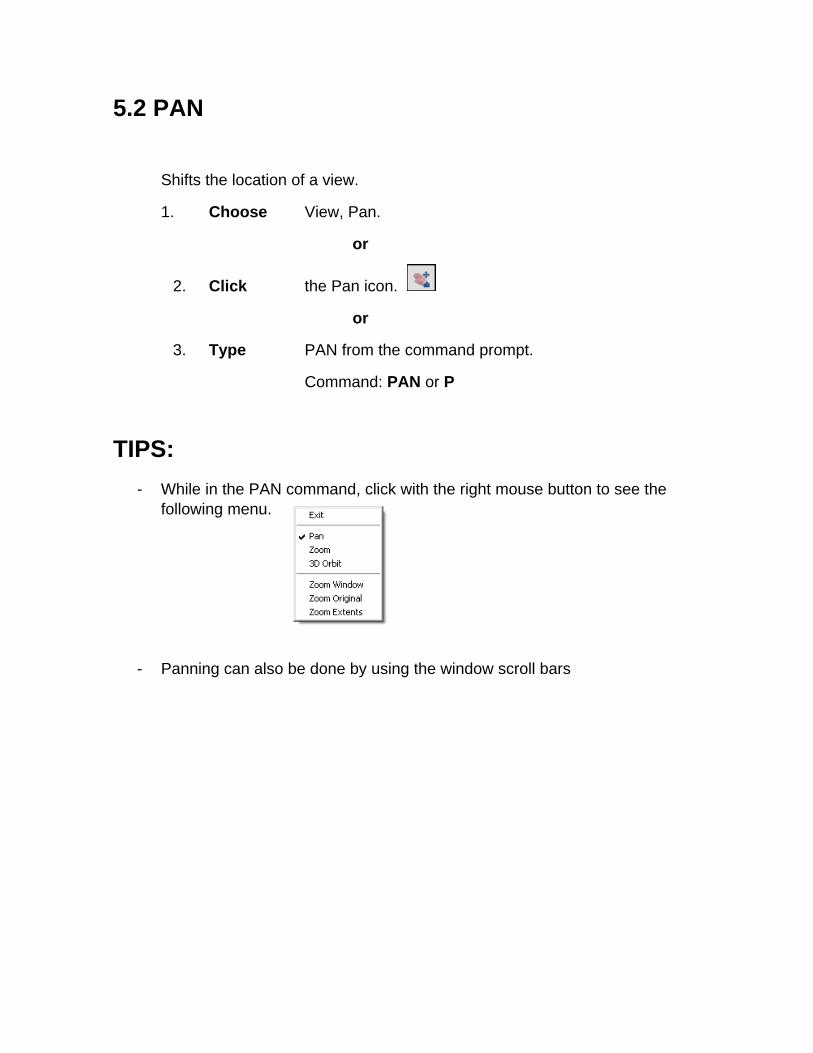
- While in the PAN command, click with the right mouse button to see the following menu.
- Panning can also be done by using the window scroll bars
5.1 ZOOM
Increases or decreases the apparent size of objects in the current viewport
1. Choose View, Zoom.
or 2. Click a Zoom icon.
or 3. Type ZOOM at the command prompt.
Command: Zoom or Z
4. Type One of the following zoom options: The following are basic zoom options: All Places entire drawing (all visible layers) on
display at once. Forces a regeneration. Extents Displays current drawing content as large as possible. Previous Restores previous view. Window Designates rectangular area to be drawn as large as
possible.
Number Magnification relative to ZOOM All display Number X Magnification relative to current display (1X) Center Specifies center point and new display height. Dynamic Permits you to pan a box representing the viewing
screen around the entire generated portion of the drawing and enlarge or shrink it.
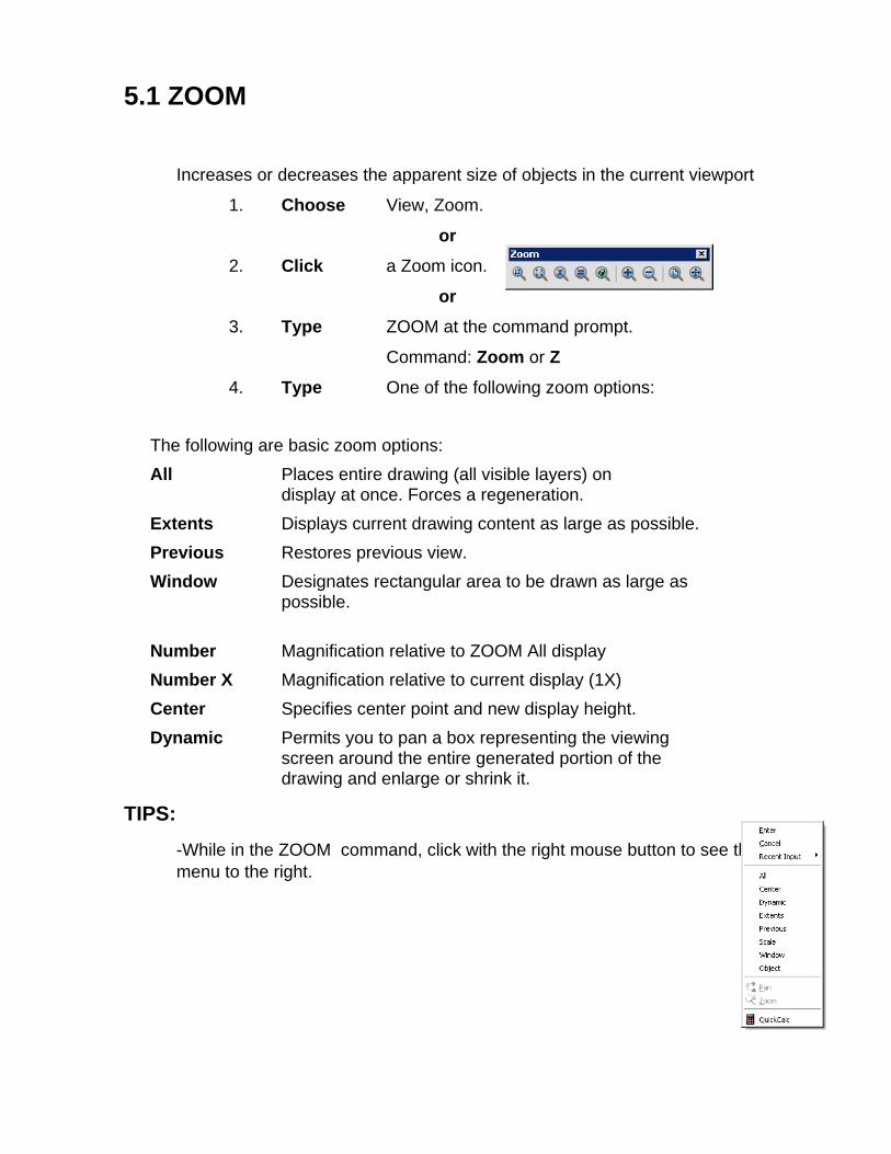
TIPS: -While in the ZOOM command, click with the right mouse button to see the menu to the right.
2.2 Creating a New Drawing NEW Command
Creates a new drawing file.
1. Choose File, New.
or
2. Press CTRL + N
or
3. Click the New icon.
or
4. Type NEW at the Command prompt.
Command: NEW
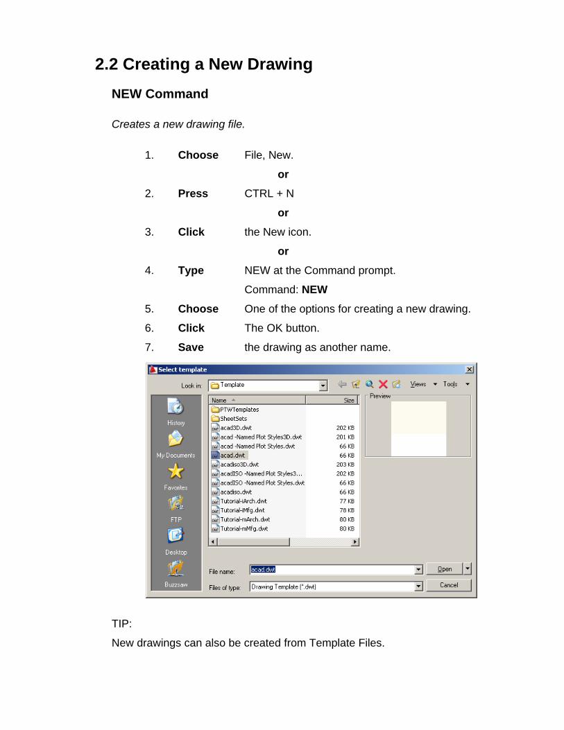
5. Choose One of the options for creating a new drawing.
6. Click The OK button.
7. Save the drawing as another name.
TIP:
New drawings can also be created from Template Files.
1.11 Undo and Redo
Reverses the last action.
1. Choose Edit, Undo.
or
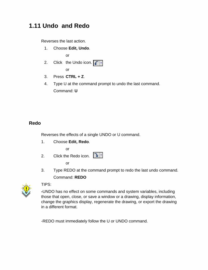
2. Click the Undo icon.
or
3. Press CTRL + Z.
4. Type U at the command prompt to undo the last command.
Command: U
Redo
Reverses the effects of a single UNDO or U command.
1. Choose Edit, Redo.
or
2. Click the Redo icon.
or
3. Type REDO at the command prompt to redo the last undo command.
Command: REDO
TIPS:
-UNDO has no effect on some commands and system variables, including those that open, close, or save a window or a drawing, display information, change the graphics display, regenerate the drawing, or export the drawing in a different format.
-REDO must immediately follow the U or UNDO command.
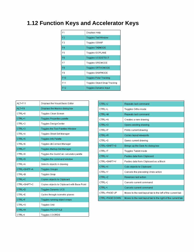
1.12 Function Keys and Accelerator Keys
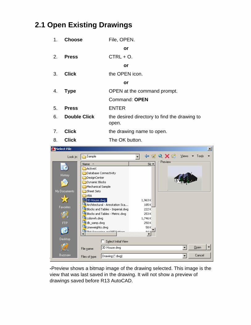
2.1 Open Existing Drawings
1. Choose File, OPEN.
or 2. Press CTRL + O.
or 3. Click the OPEN icon.
or 4. Type OPEN at the command prompt.
Command: OPEN
5. Press ENTER
6. Double Click the desired directory to find the drawing to open.
7. Click the drawing name to open.
8. Click The OK button.
TIP:
-Preview shows a bitmap image of the drawing selected. This image is the view that was last saved in the drawing. It will not show a preview of drawings saved before R13 AutoCAD.
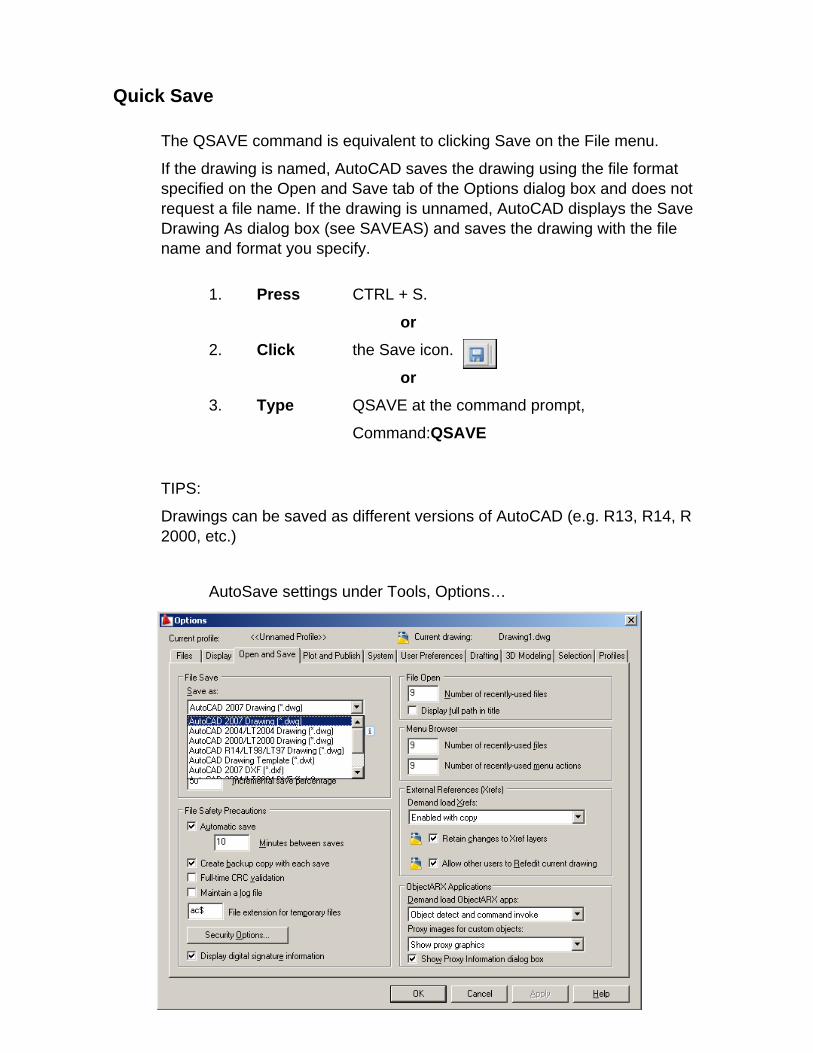
Quick Save
The QSAVE command is equivalent to clicking Save on the File menu.
If the drawing is named, AutoCAD saves the drawing using the file format specified on the Open and Save tab of the Options dialog box and does not request a file name. If the drawing is unnamed, AutoCAD displays the Save Drawing As dialog box (see SAVEAS) and saves the drawing with the file name and format you specify.
1. Press CTRL + S.
or 2. Click the Save icon.
or 3. Type QSAVE at the command prompt,
Command:QSAVE
TIPS:
Drawings can be saved as different versions of AutoCAD (e.g. R13, R14, R 2000, etc.)
AutoSave settings under Tools, Options…
Useful Commands
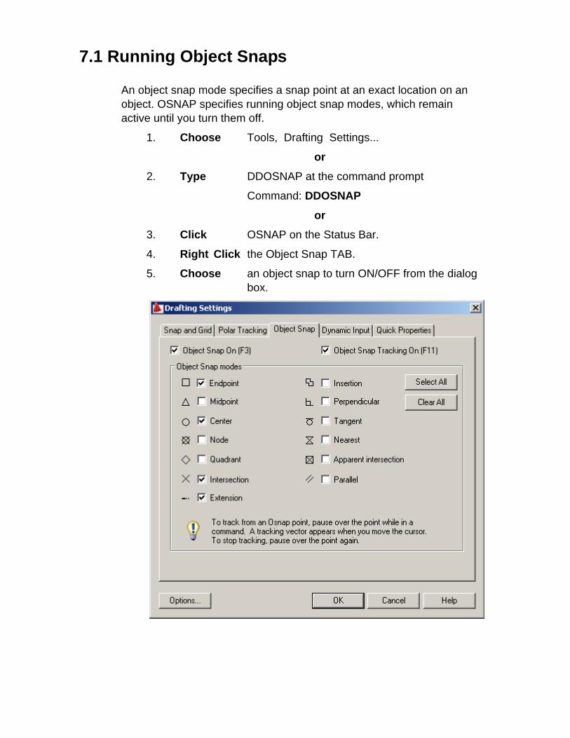
7.1 Running Object Snaps
An object snap mode specifies a snap point at an exact location on an object. OSNAP specifies running object snap modes, which remain active until you turn them off.
1. Choose Tools, Drafting Settings...
or
2. Type DDOSNAP at the command prompt
Command: DDOSNAP
or 3. Click OSNAP on the Status Bar.
4. Right Click the Object Snap TAB.
5. Choose an object snap to turn ON/OFF from the dialog box.
AutoCAD 2D Tutorial
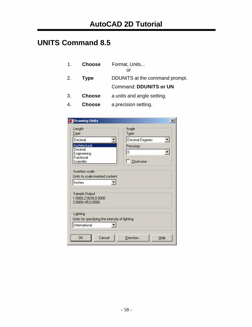
UNITS Command 8.5
1. Choose Format, Units... or
2. Type DDUNITS at the command prompt.
Command: DDUNITS or UN 3. Choose a units and angle setting. 4. Choose a precision setting.
- 58 -
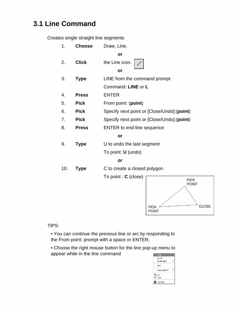
3.1 Line Command
Creates single straight line segments
1. Choose Draw, Line.
or
2. Click the Line icon.
or
3. Type LINE from the command prompt
Command: LINE or L
4. Press ENTER
5. Pick From point: (point)
6. Pick Specify next point or [Close/Undo]:(point)
7. Pick Specify next point or [Close/Undo]:(point)
8. Press ENTER to end line sequence
or
9. Type U to undo the last segment
To point: U (undo)
or 10. Type C to create a closed polygon
To point : C (close)
TIPS:
• You can continue the previous line or arc by responding to the From point: prompt with a space or ENTER.
• Choose the right mouse button for the line pop-up menu to appear while in the line command
AutoCAD 2D Tutorial
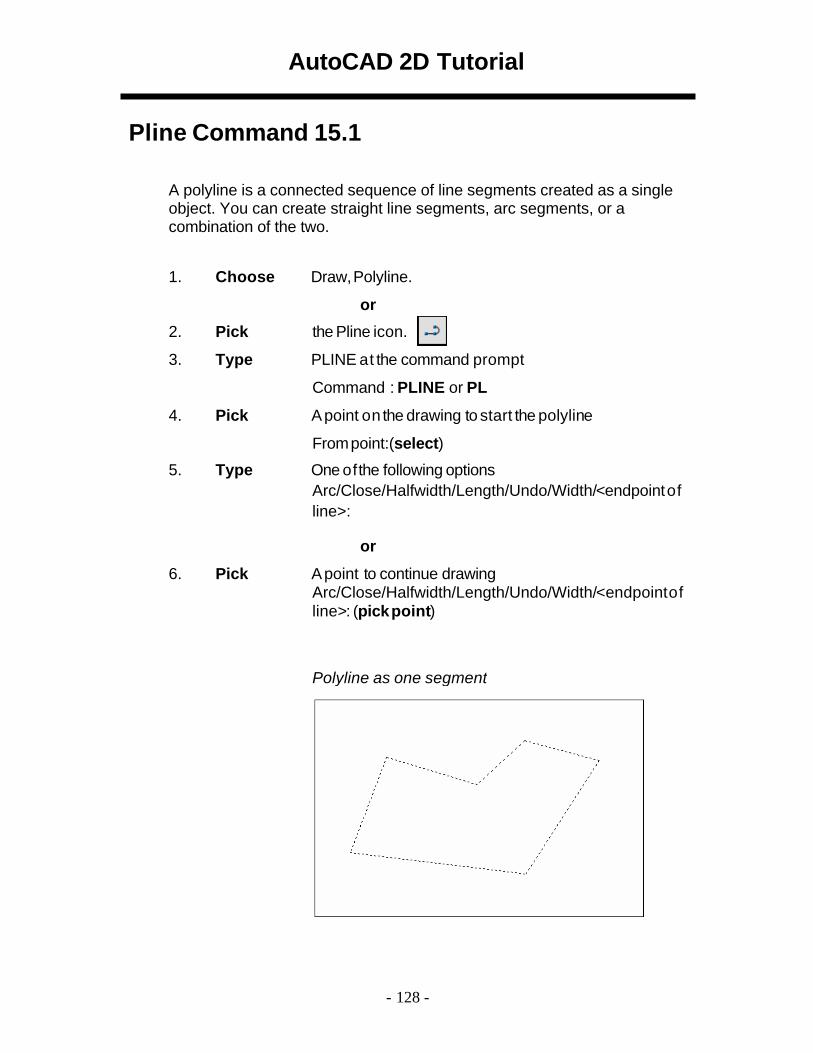
Pline Command 15.1
A polyline is a connected sequence of line segments created as a single object. You can create straight line segments, arc segments, or a combination of the two.
1. Choose Draw,Polyline.
or 2. Pick the Pline icon. 3. Type PLINE at the command prompt
Command : PLINE or PL 4. Pick A point on the drawing to start the polyline
From point:(select) 5. Type One of the following options
Arc/Close/Halfwidth/Length/Undo/Width/<endpoint of line>:
or
6. Pick A point to continue drawing Arc/Close/Halfwidth/Length/Undo/Width/<endpoint of line>: (pick point)
Polyline as one segment
- 128 -
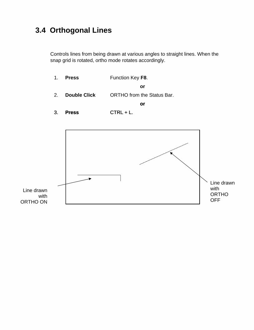
3.4 Orthogonal Lines
Controls lines from being drawn at various angles to straight lines. When the snap grid is rotated, ortho mode rotates accordingly.
1. Press Function Key F8.
or 2. Double Click ORTHO from the Status Bar.
or or 3. Press CTRL + L. 3. Press CTRL + L.
Line drawn with
ORTHO ON
Line drawn with ORTHO OFF
AutoCAD 2D Tutorial
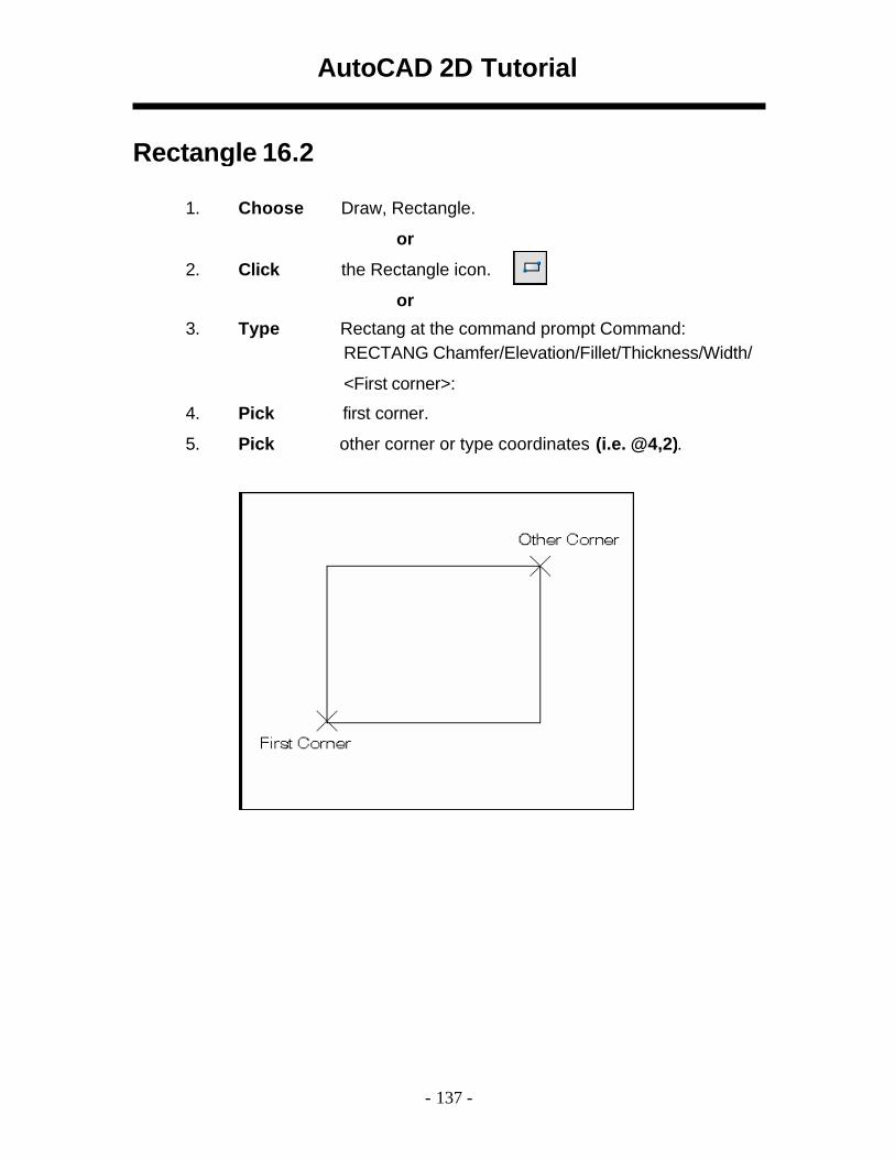
Rectangle 16.2
1. Choose Draw, Rectangle.
or 2. Click the Rectangle icon.
or 3. Type Rectang at the command prompt Command:
RECTANG Chamfer/Elevation/Fillet/Thickness/Width/
<First corner>: 4. Pick first corner. 5. Pick other corner or type coordinates (i.e. @4,2).
- 137 -
3.6 Circles
Circle Command
1. Choose Draw, Circle.
or 2. Click the Circle icon.
or 3. Type CIRCLE at the command prompt.
Command: CIRCLE
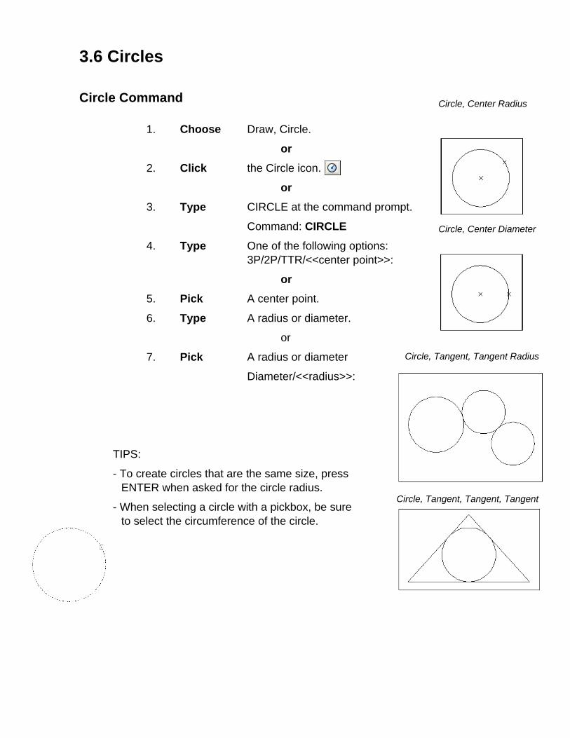
4. Type One of the following options: 3P/2P/TTR/<<center point>>:
Circle, Center Radius
Circle, Center Diameter
Circle, Tangent, Tangent Radius
Circle, Tangent, Tangent, Tangent
or 5. Pick A center point.
6. Type A radius or diameter.
or
7. Pick A radius or diameter
Diameter/<<radius>>:
TIPS:
- To create circles that are the same size, press ENTER when asked for the circle radius.
- When selecting a circle with a pickbox, be sure to select the circumference of the circle.
3.7 Arc Command
1. Choose Draw, Arc.
or
2. Click the Arc icon.
or
3. Type ARC at the command prompt
Command: ARC
4. Draw One of the arcs.
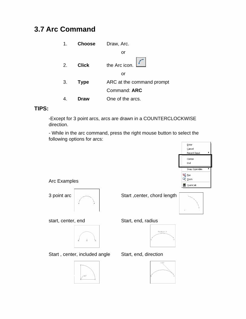
TIPS: -Except for 3 point arcs, arcs are drawn in a COUNTERCLOCKWISE direction.
- While in the arc command, press the right mouse button to select the following options for arcs:
Arc Examples
3 point arc Start ,center, chord length
start, center, end Start, end, radius
Start , center, included angle Start, end, direction
AutoCAD 2D Tutorial
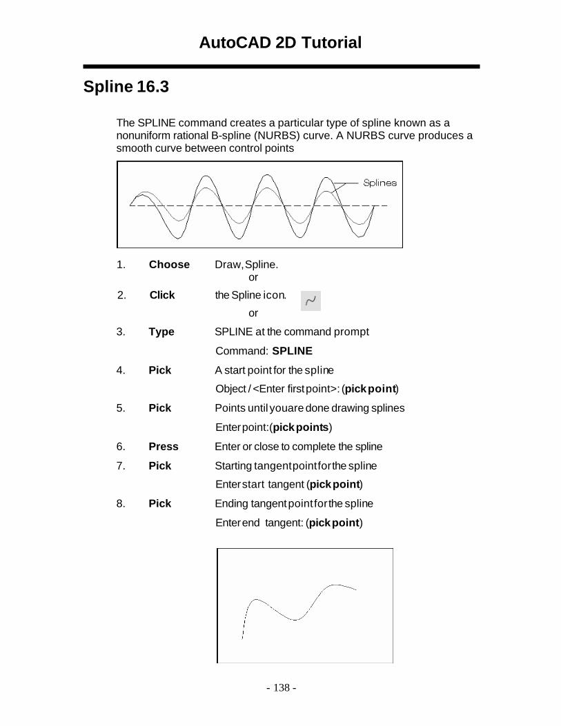
Spline 16.3
The SPLINE command creates a particular type of spline known as a nonuniform rational B-spline (NURBS) curve. A NURBS curve produces a smooth curve between control points
1. Choose Draw, Spline. or
2. Click the Spline icon. or
3. Type SPLINE at the command prompt
Command: SPLINE 4. Pick A start point for the spline
Object / <Enter first point>: (pick point) 5. Pick Points until youare done drawing splines
Enter point:(pick points) 6. Press Enter or close to complete the spline 7. Pick Starting tangent point for the spline
Enter start tangent (pick point) 8. Pick Ending tangent point for the spline
Enter end tangent: (pick point)
- 138 -

Editing
AutoCAD 2D Tutorial
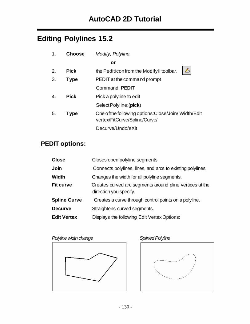
Editing Polylines 15.2
1. Choose Modify, Polyline.
or 2. Pick the Pedit icon from the Modify II toolbar. 3. Type PEDIT at the comma nd prompt
Command: PEDIT 4. Pick Pick a polyline to edit
Select Polyline:(pick)
5. Type One of the following options:Close/Join/ Width/Edit vertex/FitCurve/Spline/Curve/
Decurve/Undo/eXit
PEDIT options:
Close Closes open polyline segments Join Connects polylines, lines, and arcs to existing polylines. Width Changes the width for all polyline segments. Fit curve Creates curved arc segments around pline vertices at the
direction you specify. Spline Curve Creates a curve through control points on a polyline. Decurve Straightens curved segments. Edit Vertex Displays the following Edit Vertex Options:
Polyline width change SplinedPolyline
- 130 -
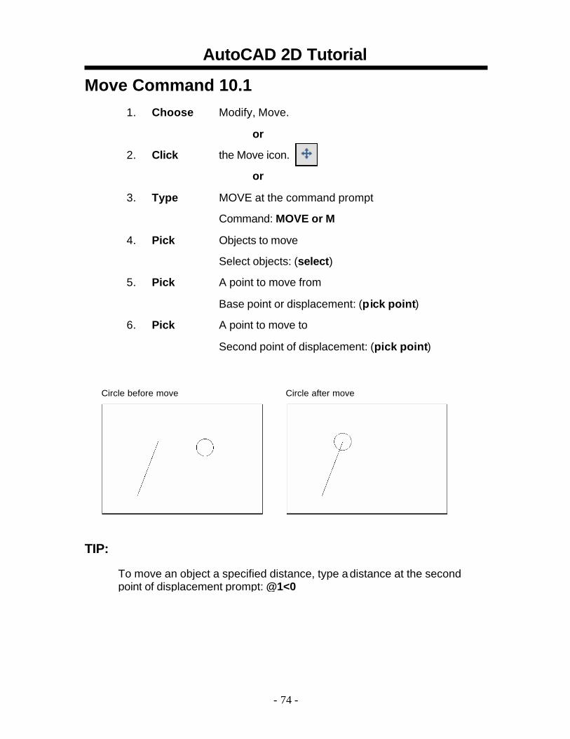
AutoCAD 2D Tutorial Move Command 10.1
1. Choose Modify, Move.
or 2. Click the Move icon.
or 3. Type MOVE at the command prompt
Command: MOVE or M 4. Pick Objects to move
Select objects: (select) 5. Pick A point to move from
Base point or displacement: (pick point) 6. Pick A point to move to
Second point of displacement: (pick point)
Circle before move Circle after move
TIP:
To move an object a specified distance, type a distance at the second point of displacement prompt: @1<0
- 74 -
AutoCAD 2D Tutorial
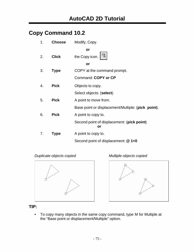
Copy Command 10.21. Choose Modify, Copy.
or 2. Click the Copy icon.
or
3. Type COPY at the command prompt.
Command: COPY or CP 4. Pick Objects to copy.
Select objects: (select) 5. Pick A point to move from.
Base point or displacement/Multiple: (pick point). 6. Pick A point to copy to.
Second point of displacement: (pick point) or
7. Type A point to copy to.
Second point of displacement: @ 1<0
Duplicate objects copied Multiple objects copied
TIP:
• To copy many objects in the same copy command, type M for Multiple at the “Base point or displacement/Multiple” option.
- 75 -
AutoCAD 2D Tutorial
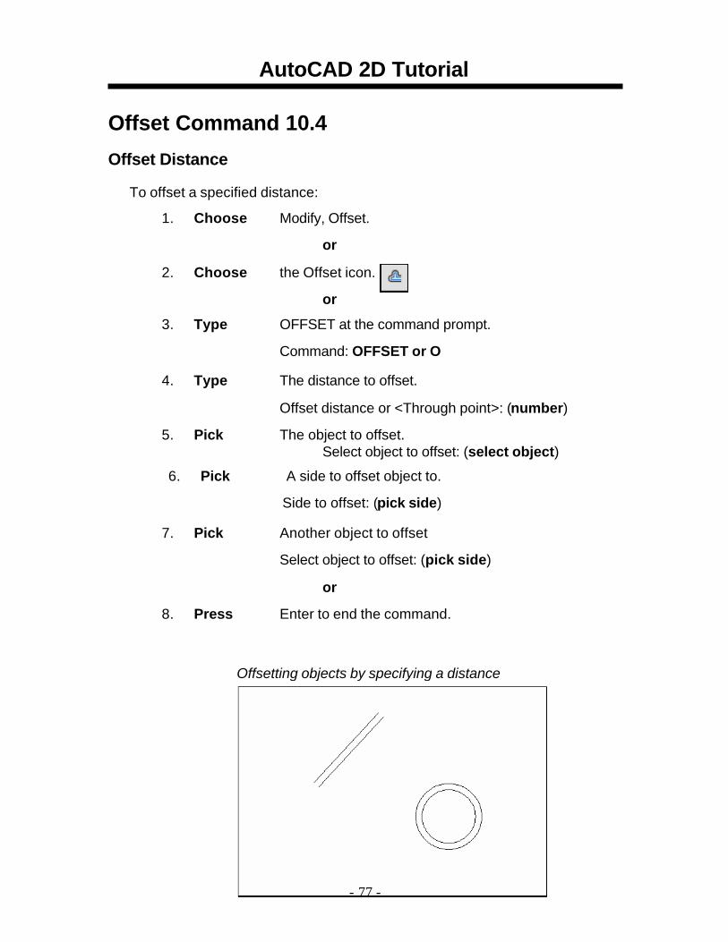
Offset Command 10.4 Offset Distance
To offset a specified distance:
1. Choose Modify, Offset.
or
2. Choose the Offset icon.
or
3. Type OFFSET at the command prompt.
Command: OFFSET or O
4. Type The distance to offset.
Offset distance or <Through point>: (number)
5. Pick The object to offset. Select object to offset: (select object)
6. Pick A side to offset object to.
Side to offset: (pick side)
7. Pick Another object to offset
Select object to offset: (pick side)
or
8. Press Enter to end the command.
Offsetting objects by specifying a distance
- 77 -
AutoCAD 2D Tutorial
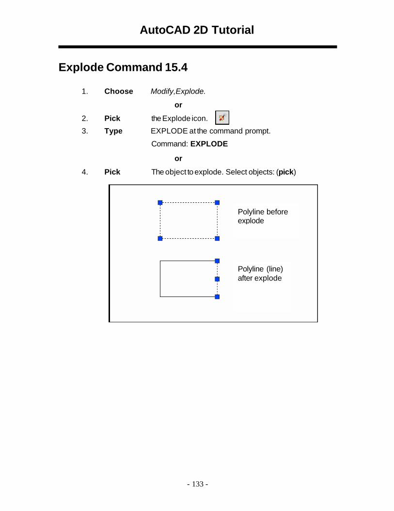
Explode Command 15.4
1. Choose Modify,Explode.
or 2. Pick the Explode icon. 3. Type EXPLODE at the command prompt.
Command: EXPLODE
or 4. Pick The object toexplode. Select objects: (pick)
Polyline before explode
Polyline (line) after explode
- 133 -
AutoCAD 2D Tutorial
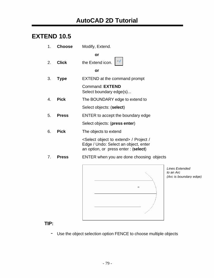
EXTEND 10.5 1. Choose Modify, Extend.
or 2. Click the Extend icon.
or 3. Type EXTEND at the command prompt
Command: EXTEND Select boundary edge(s)...
4. Pick The BOUNDARY edge to extend to
Select objects: (select) 5. Press ENTER to accept the boundary edge
Select objects: (press enter) 6. Pick The objects to extend
<Select object to extend> / Project / Edge / Undo: Select an object, enter an option, or press enter : (select)
7. Press ENTER when you are done choosing objects
Lines Extended to an Arc (Arc is boundary edge)
TIP:
- Use the object selection option FENCE to choose multiple objects
- 79 -
AutoCAD 2D Tutorial
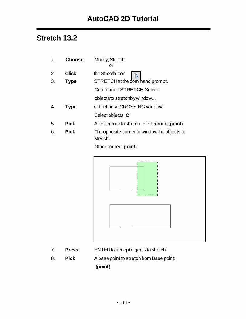
Stretch 13.2
1. Choose Modify, Stretch. or
2. Click the Stretch icon. 3. Type STRETCHat the command prompt.
Command : STRETCH Select
objects to stretchby window... 4. Type C to choose CROSSING window
Select objects: C 5. Pick A first corner to stretch. First corner: (point) 6. Pick The opposite corner to window the objects to
stretch.
Other corner: (point)
7. Press ENTERto acceptobjects to stretch. 8. Pick A base point to stretch from Base point:
(point)
- 114 -
AutoCAD 2D Tutorial
9. Pick A point tostretch to Newpoint: (point)
or 10. Type A distance to stretch. Newpoint: @1<0
TIP:
The Stretch command must use a CROSSING window or aCROSSING POLYGON window.
- 115 -
AutoCAD 2D Tutorial
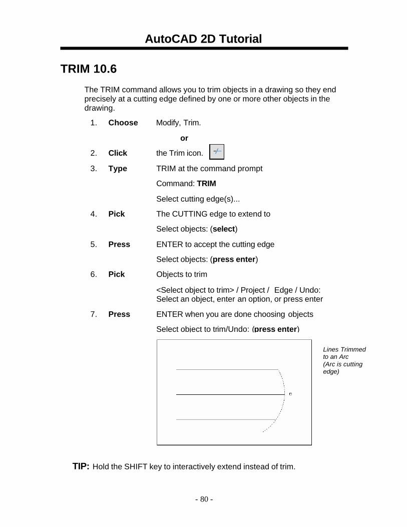
TRIM 10.6 The TRIM command allows you to trim objects in a drawing so they end precisely at a cutting edge defined by one or more other objects in the drawing.
1. Choose Modify, Trim.
or
2. Click the Trim icon.
3. Type TRIM at the command prompt
Command: TRIM
Select cutting edge(s)...
4. Pick The CUTTING edge to extend to
Select objects: (select)
5. Press ENTER to accept the cutting edge
Select objects: (press enter)
6. Pick Objects to trim
<Select object to trim> / Project / Edge / Undo: Select an object, enter an option, or press enter
7. Press ENTER when you are done choosing objects
Select object to trim/Undo: (press enter)
Lines Trimmed to an Arc (Arc is cutting edge)
TIP: Hold the SHIFT key to interactively extend instead of trim.
- 80 -
AutoCAD 2D Tutorial
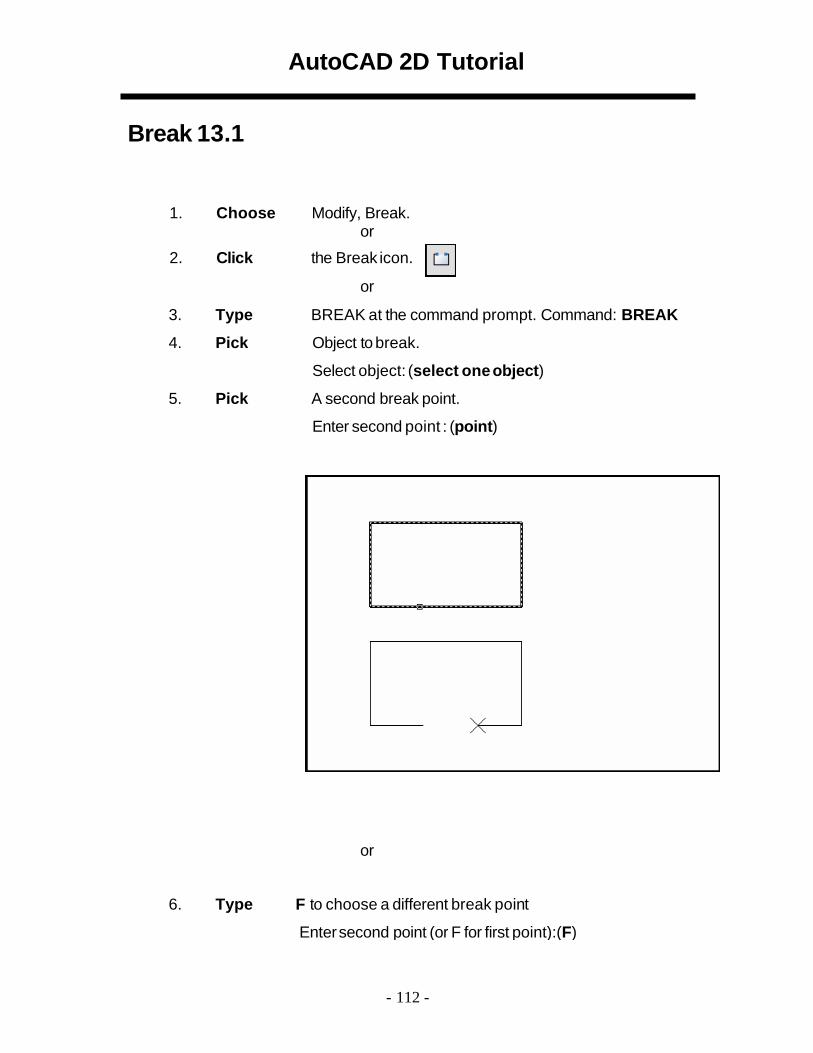
Break 13.1
1. Choose Modify, Break. or
2. Click the Break icon.
or 3. Type BREAK at the command prompt. Command: BREAK 4. Pick Object to break.
Select object: (select one object) 5. Pick A second break point.
Enter second point : (point)
or
6. Type F to choose a different break point
Entersecond point (or F for first point):(F)
- 112 -
AutoCAD 2D Tutorial
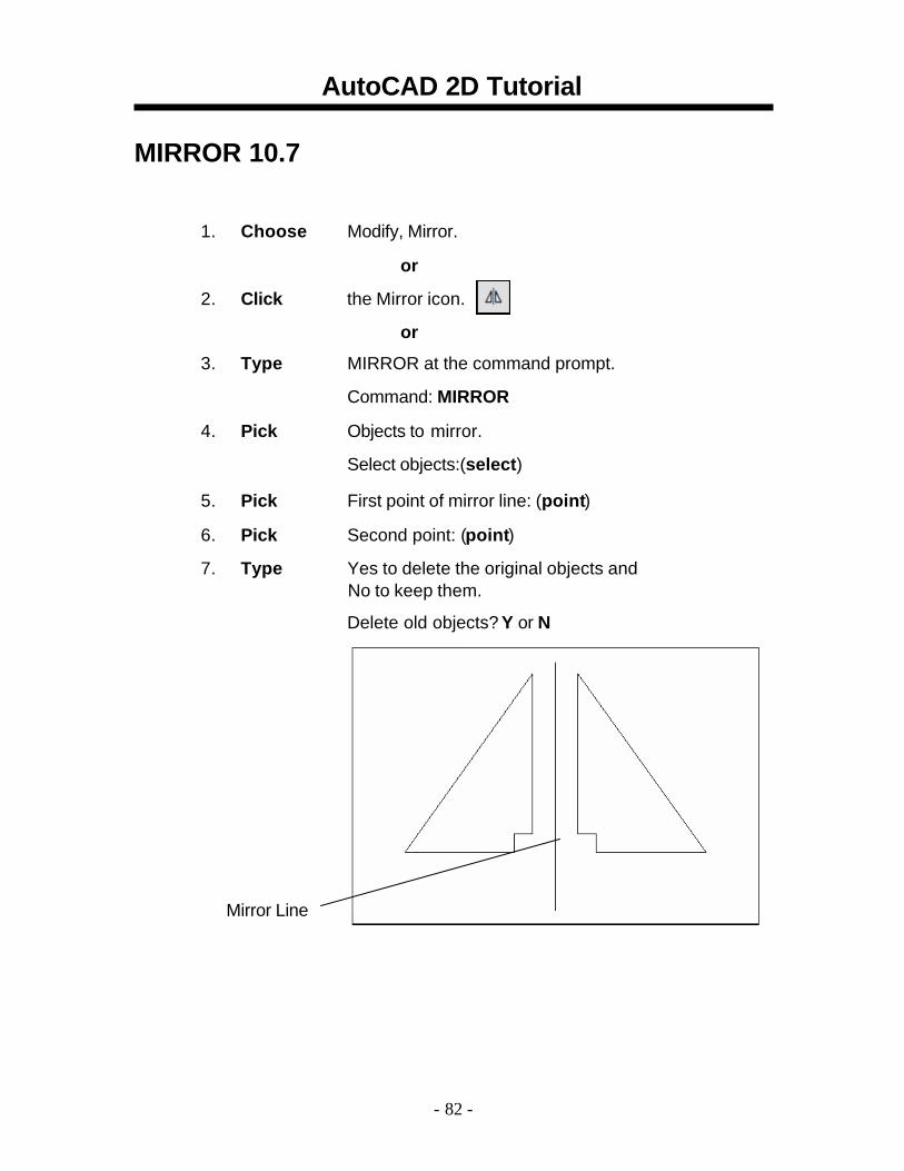
MIRROR 10.7
1. Choose Modify, Mirror.
or 2. Click the Mirror icon.
or
3. Type MIRROR at the command prompt.
Command: MIRROR
4. Pick Objects to mirror.
Select objects:(select) 5. Pick First point of mirror line: (point) 6. Pick Second point: (point) 7. Type Yes to delete the original objects and
No to keep them.
Delete old objects? Y or N
Mirror Line
- 82 -
AutoCAD 2D Tutorial
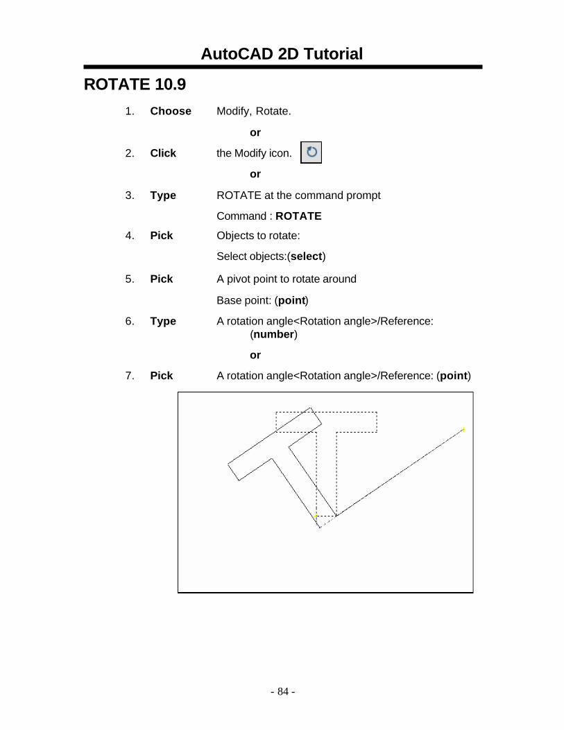
ROTATE 10.9 1. Choose Modify, Rotate.
or 2. Click the Modify icon.
or 3. Type ROTATE at the command prompt
Command : ROTATE
4. Pick Objects to rotate:
Select objects:(select) 5. Pick A pivot point to rotate around
Base point: (point) 6. Type A rotation angle<Rotation angle>/Reference:
(number)
or 7. Pick A rotation angle<Rotation angle>/Reference: (point)
- 84 -
AutoCAD 2D Tutorial
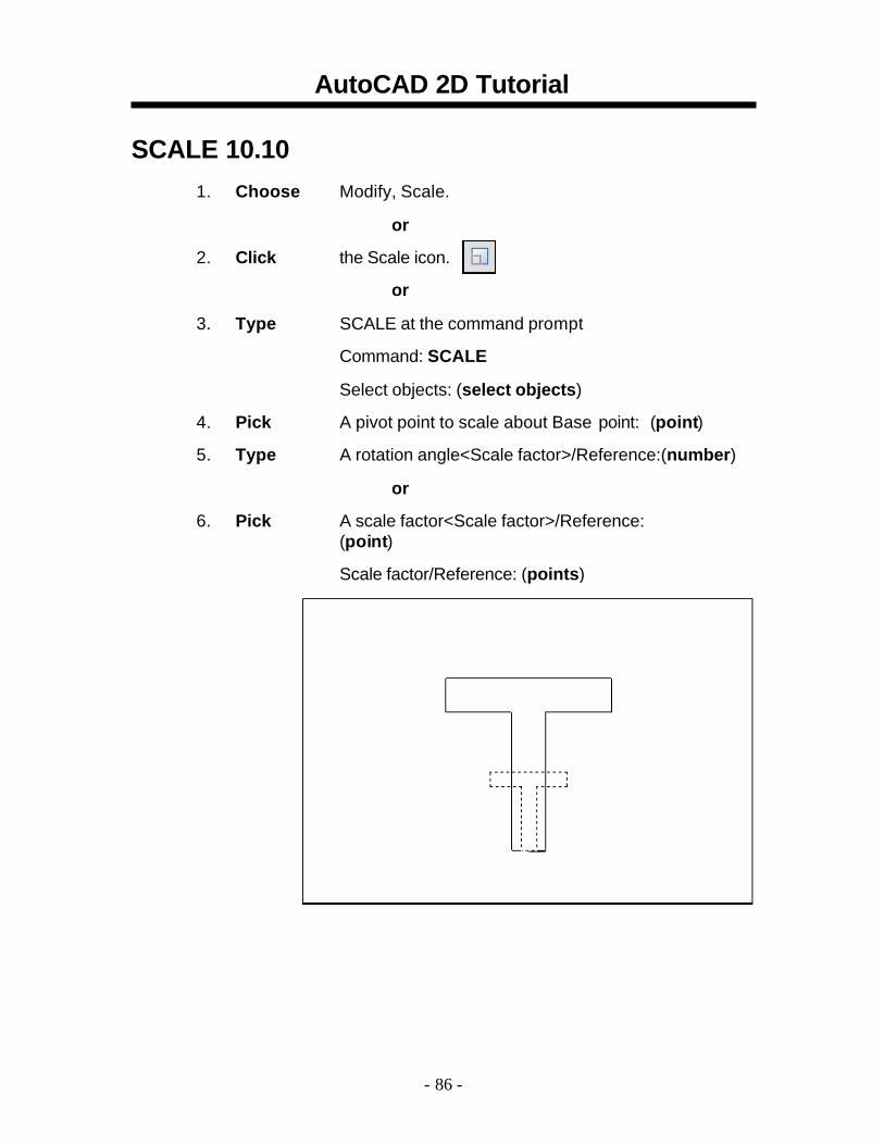
SCALE 10.10 1. Choose Modify, Scale.
or 2. Click the Scale icon.
or 3. Type SCALE at the command prompt
Command: SCALE
Select objects: (select objects) 4. Pick A pivot point to scale about Base point: (point) 5. Type A rotation angle<Scale factor>/Reference:(number)
or 6. Pick A scale factor<Scale factor>/Reference:
(point)
Scale factor/Reference: (points)
- 86 -

AutoCAD 2D Tutorial Text Command 11.1 Text
Creates a single-line text object
1. Type TEXT at the command prompt
Command: TEXT
or
2. Pick the Single Line Text icon from the Text Toolbar.
3. Pick A start point
Justify/Style/<Start Point>: (point)
or
4. Type J to change the justification or S to change the text style.
5. Type A text height
Height <default>: (type value or pick two points)
6. Type A rotation angle
Rotation angle <default>: (angle or point)
7. Type A text string
Text: (type text string)
8. Press enter to exit the Text: prompt.
DTEXT (Dynamic Text)
Creates a single-line text object, showing the text dynamically on the screen as it is entered. 1. Choose Draw, Text, Single Line Text.
or 2. Type DTEXT at the command prompt
Command : DTEXT 3. Follow the steps 3-8 from above.
- 89 -
Layers
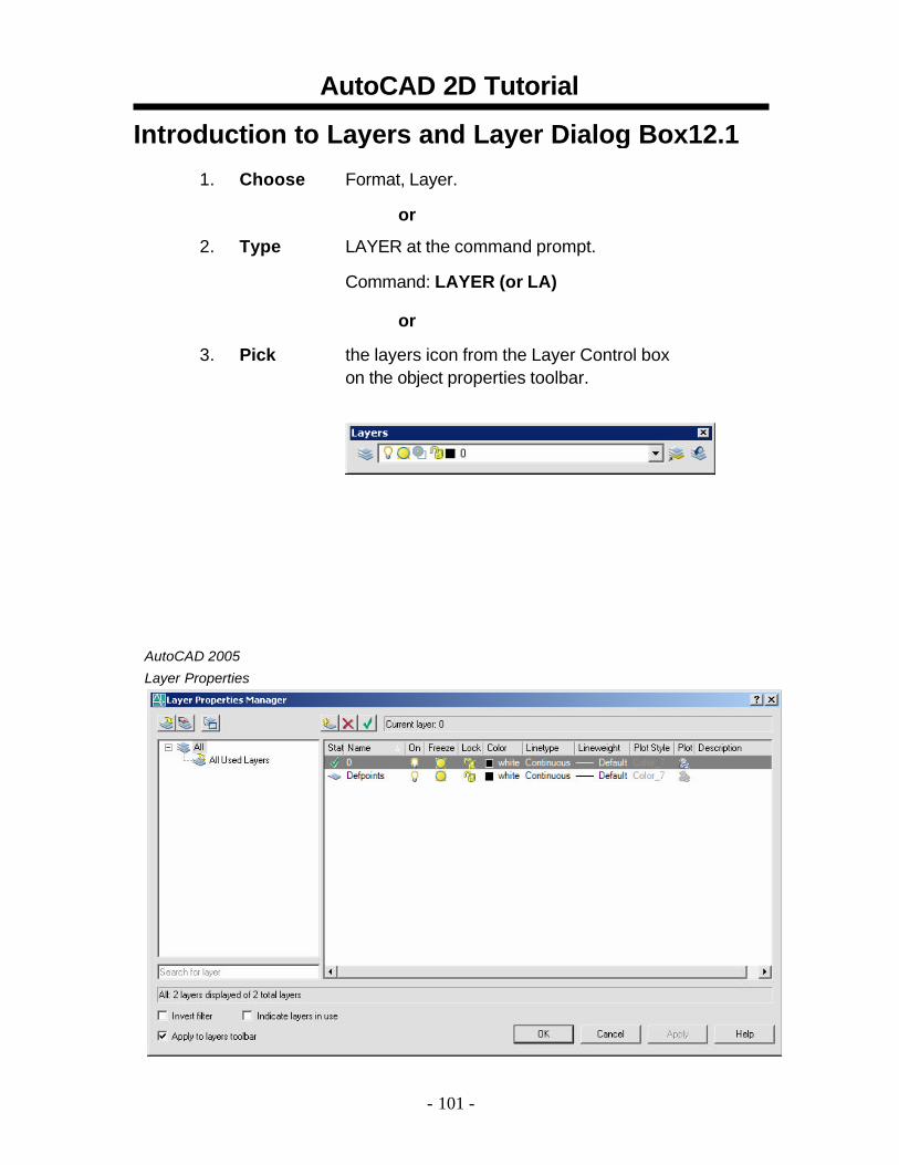
AutoCAD 2D Tutorial Introduction to Layers and Layer Dialog Box12.1
1. Choose Format, Layer.
or
2. Type LAYER at the command prompt.
Command: LAYER (or LA)
or
3. Pick the layers icon from the Layer Control box on the object properties toolbar.
AutoCAD 2005
Layer Properties
- 101 -
AutoCAD 2D Tutorial Layer Options 12.2
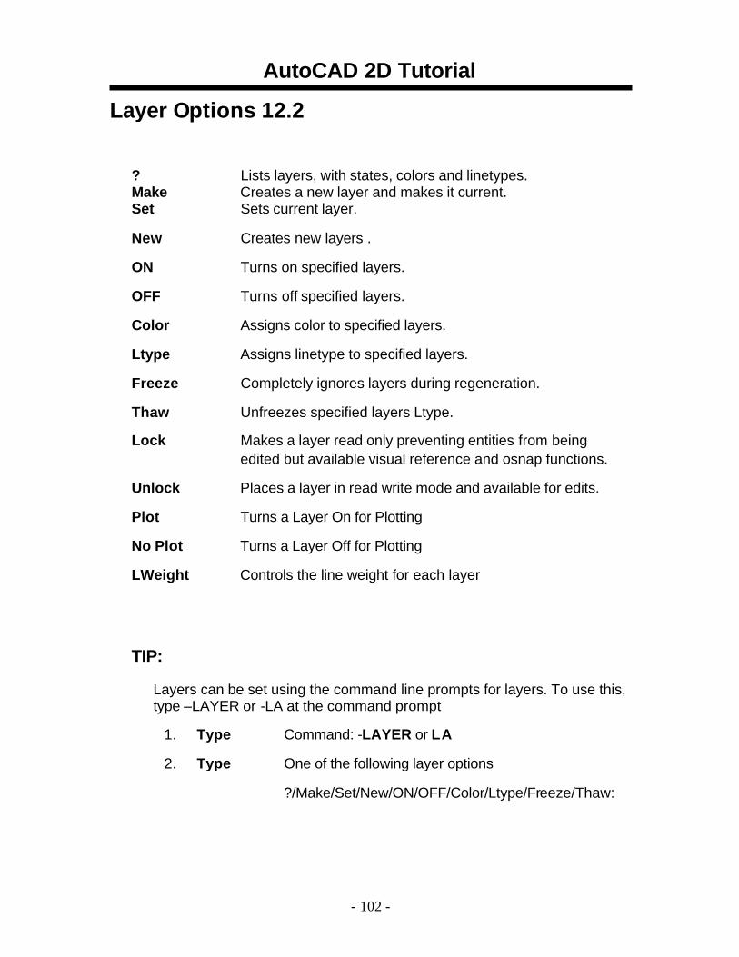
? Lists layers, with states, colors and linetypes. Make Creates a new layer and makes it current. Set Sets current layer. New Creates new layers . ON Turns on specified layers. OFF Turns off specified layers. Color Assigns color to specified layers. Ltype Assigns linetype to specified layers. Freeze Completely ignores layers during regeneration. Thaw Unfreezes specified layers Ltype.
Lock Makes a layer read only preventing entities from being edited but available visual reference and osnap functions.
Unlock Places a layer in read write mode and available for edits. Plot Turns a Layer On for Plotting No Plot Turns a Layer Off for Plotting LWeight Controls the line weight for each layer
TIP:
Layers can be set using the command line prompts for layers. To use this, type –LAYER or -LA at the command prompt
1. Type Command: -LAYER or LA
2. Type One of the following layer options
?/Make/Set/New/ON/OFF/Color/Ltype/Freeze/Thaw:
- 102 -
AutoCAD 2D Tutorial
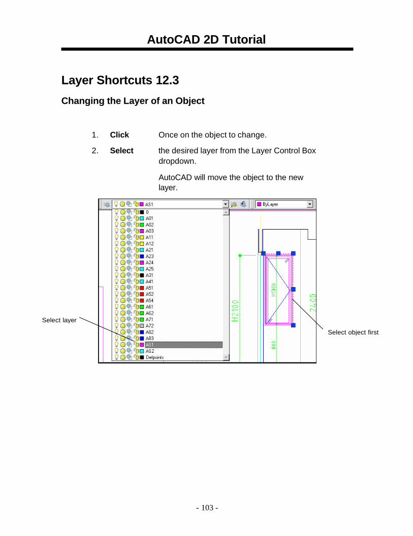
Layer Shortcuts 12.3 Changing the Layer of an Object
1. Click Once on the object to change.
2. Select the desired layer from the Layer Control Box dropdown.
AutoCAD will move the object to the new layer.
Select layer
Select object first
- 103 -

Colours + Line Weights

AutoCAD 2D Tutorial Color Command 12.6
1. Choose Format, Color.
or
2. Type DDCOLOR at the command prompt.
Command: DDCOLOR or COL
or 3. Choose Color on the Object Properties toolbar and then
select a color from the list or select Other to display the Select Color dialog box.
TIP:
These settings ignore the current layer settings for color. By Layer
If you enter bylayer, new objects assume the color of the layer upon which they are drawn.
By Block
If you enter byblock, AutoCAD draws new objects in the default color (white or black, depending on your configuration) until they are grouped into a block. When the block is inserted in the drawing, the objects in the bloc k inherit the current setting of the COLOR command.
- 107 -
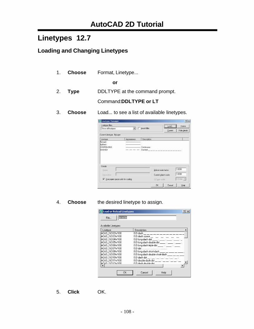
AutoCAD 2D Tutorial Linetypes 12.7 Loading and Changing Linetypes
1. Choose Format, Linetype...
or
2. Type DDLTYPE at the command prompt.
Command:DDLTYPE or LT 3. Choose Load... to see a list of available linetypes.
4. Choose the desired linetype to assign.
5. Click OK.
- 108 -
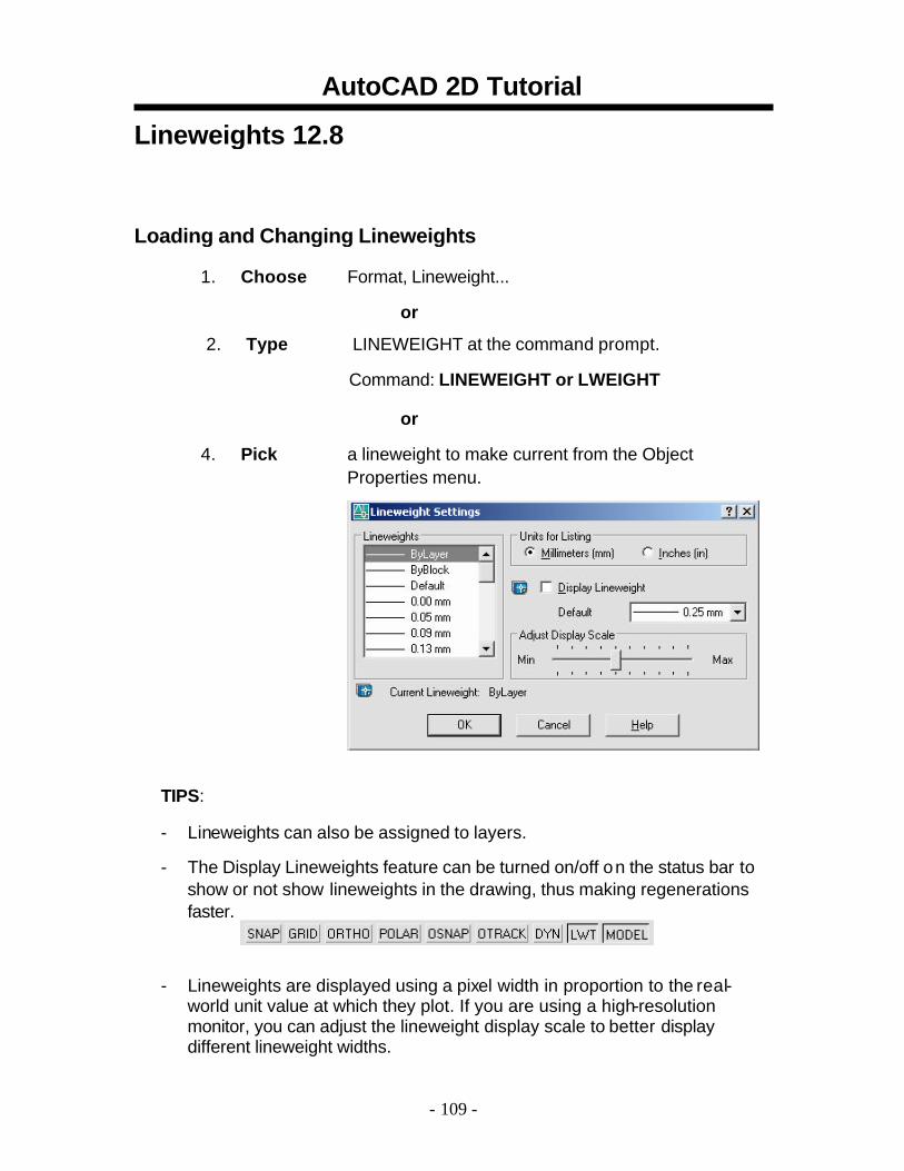
AutoCAD 2D Tutorial Lineweights 12.8
Loading and Changing Lineweights
1. Choose Format, Lineweight...
or
2. Type LINEWEIGHT at the command prompt.
Command: LINEWEIGHT or LWEIGHT
or 4. Pick a lineweight to make current from the Object
Properties menu.
TIPS:
- Lineweights can also be assigned to layers. - The Display Lineweights feature can be turned on/off o n the status bar to
show or not show lineweights in the drawing, thus making regenerations faster.
- Lineweights are displayed using a pixel width in proportion to the real-world unit value at which they plot. If you are using a high-resolution monitor, you can adjust the lineweight display scale to better display different lineweight widths.
- 109 -
AutoCAD 2D Tutorial
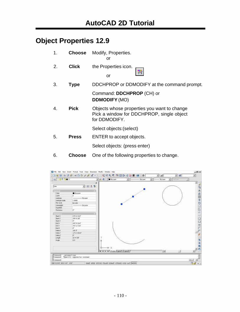
Object Properties 12.91. Choose Modify, Properties.
or
2. Click the Properties icon.
or
3. Type DDCHPROP or DDMODIFY at the command prompt.
Command: DDCHPROP (CH) or DDMODIFY (MO)
4. Pick Objects whose properties you want to change
Pick a window for DDCHPROP, single object for DDMODIFY.
Select objects:(select)
5. Press ENTER to accept objects.
Select objects: (press enter) 6. Choose One of the following properties to change.
- 110 -

Other Useful Functions
AutoCAD 2D Tutorial
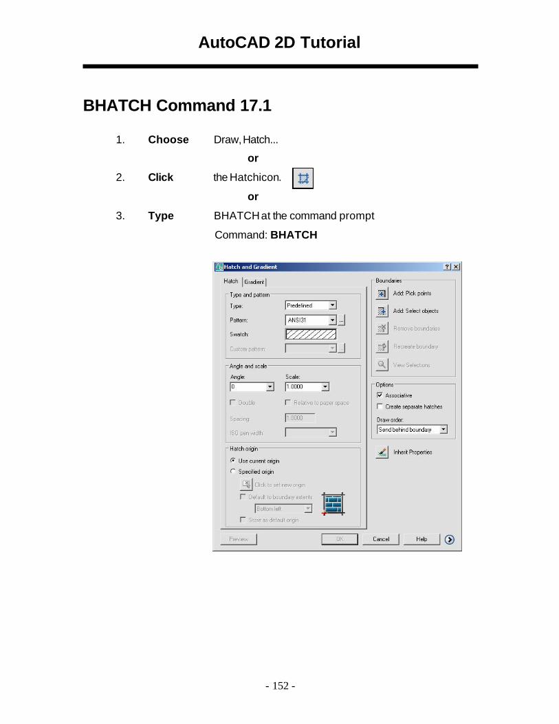
BHATCH Command 17.1
1. Choose Draw,Hatch...
or 2. Click the Hatchicon.
or 3. Type BHATCH at the command prompt
Command: BHATCH
- 152 -
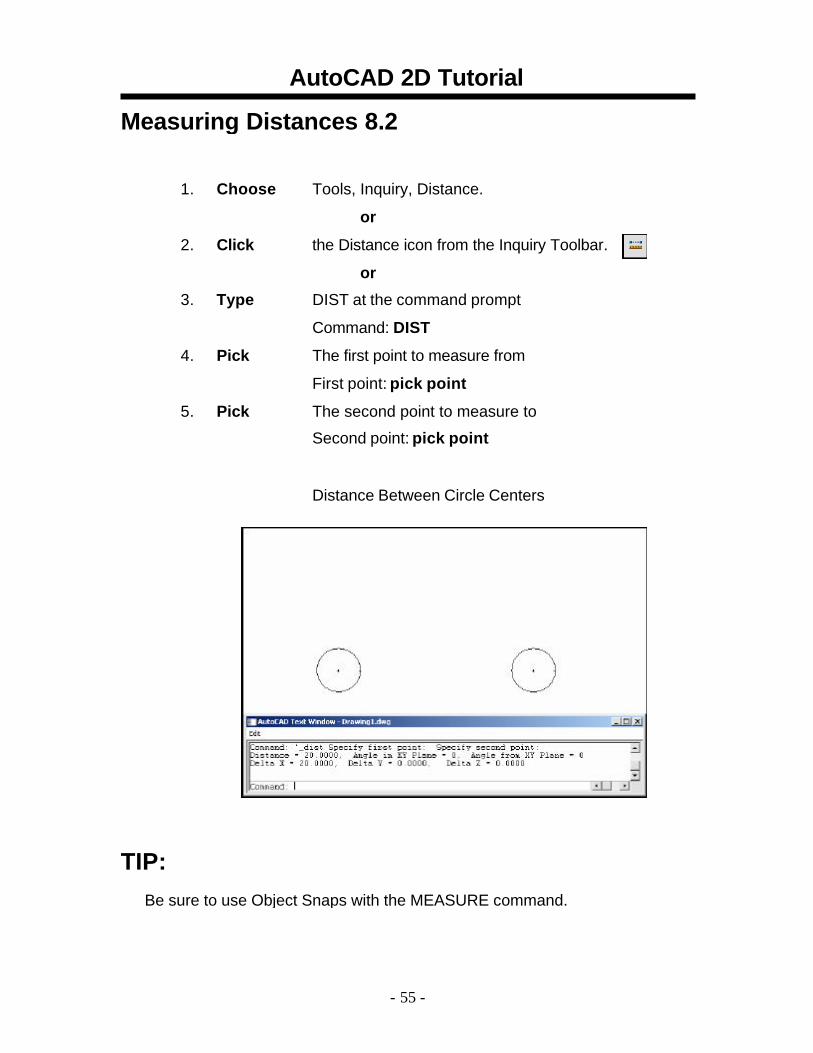
AutoCAD 2D Tutorial Measuring Distances 8.2
1. Choose Tools, Inquiry, Distance.
or 2. Click the Distance icon from the Inquiry Toolbar.
or 3. Type DIST at the command prompt
Command: DIST 4. Pick The first point to measure from
First point: pick point 5. Pick The second point to measure to
Second point: pick point
Distance Between Circle Centers
TIP: Be sure to use Object Snaps with the MEASURE command.
- 55 -

AutoCAD 2D Tutorial
Linear Dimensions 26.1
1 . Choose Dimension, Linear.
or 2 . Click the Linear Dimension command from the toolbar.
or3 . Type DIM at the command prompt.
Command: DIM
Dim: HOR or VER
- 223 -
AutoCAD 2D Tutorial
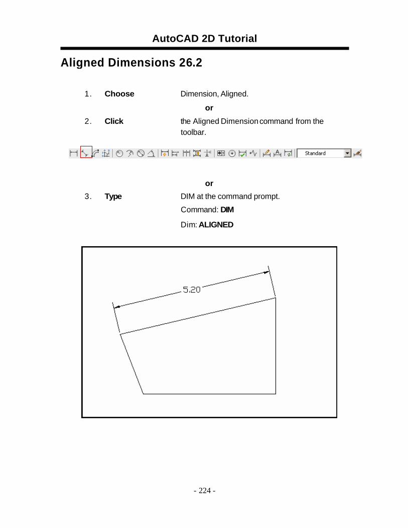
Aligned Dimensions 26.2
1 . Choose Dimension, Aligned.
or 2 . Click the Aligned Dimension command from the
toolbar.
or3 . Type DIM at the command prompt.
Command: DIM
Dim: ALIGNED
- 224 -
AutoCAD 2D Tutorial
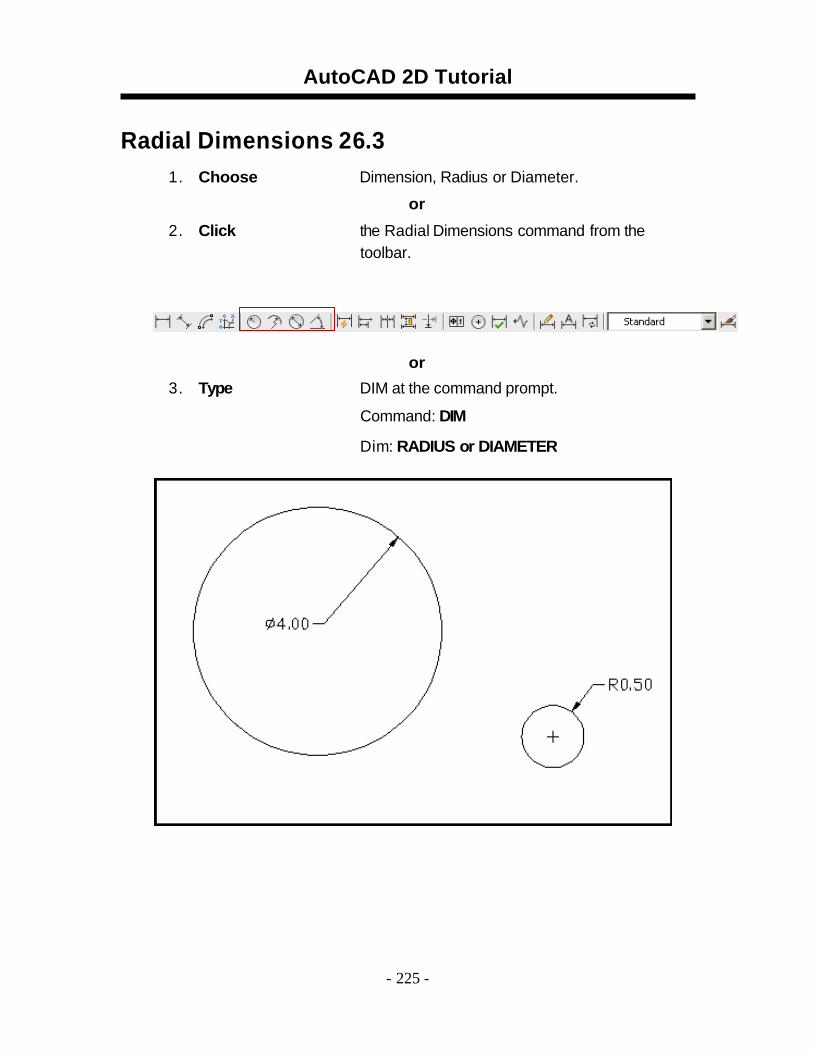
Radial Dimensions 26.31 . Choose Dimension, Radius or Diameter.
or 2 . Click the Radial Dimensions command from the
toolbar.
or3 . Type DIM at the command prompt.
Command: DIM
Dim: RADIUS or DIAMETER
- 225 -
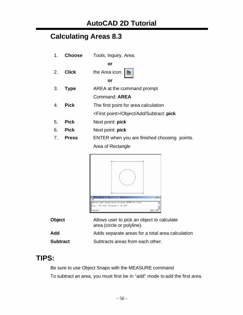
AutoCAD 2D Tutorial Calculating Areas 8.3
1. Choose Tools, Inquiry, Area.
or 2. Click the Area icon.
or 3. Type AREA at the command prompt
Command: AREA 4. Pick The first point for area calculation
<First point>/Object/Add/Subtract: pick 5. Pick Next point: pick 6. Pick Next point: pick 7. Press ENTER when you are finished choosing points.
Area of Rectangle
Object Allows user to pick an object to calculate area (circle or polyline).
Add Adds separate areas for a total area calculation Subtract Subtracts areas from each other.
TIPS:
Be sure to use Object Snaps with the MEASURE command
To subtract an area, you must first be in “add” mode to add the first area.
- 56 -
AutoCAD 2D Tutorial
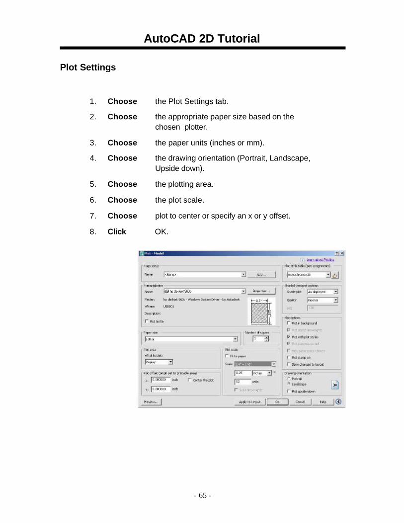
Plot Settings
1. Choose the Plot Settings tab.
2. Choose the appropriate paper size based on the chosen plotter.
3. Choose the paper units (inches or mm).
4. Choose the drawing orientation (Portrait, Landscape, Upside down).
5. Choose the plotting area. 6. Choose the plot scale. 7. Choose plot to center or specify an x or y offset. 8. Click OK.
- 65 -
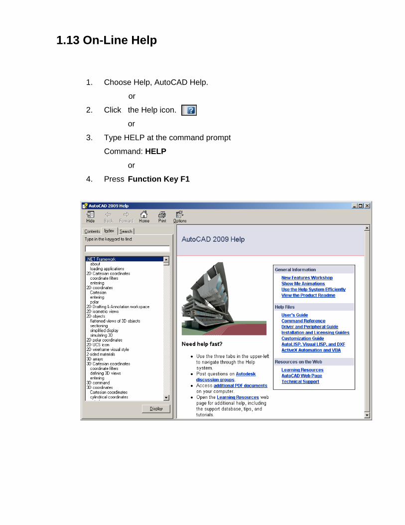
1.13 On-Line Help
1. Choose Help, AutoCAD Help.
or
2. Click the Help icon.
or
3. Type HELP at the command prompt
Command: HELP
or
4. Press Function Key F1


