BLRT Automac Bond , Loop & Joint Resistance Test System 200Hz Version APPROVED by The Boeing Company Approved alternave to the LRT Loop Resistance Tester (906-10246-3; 906-10247-3; 906-10276-3) Suitable for non-explosive environments
Transcript
BLRTAutomatic Bond , Loop & JointResistance Test System
200Hz VersionAPPROVED by The Boeing Company
Approved alternative to the LRT Loop Resistance Tester
(906-10246-3; 906-10247-3; 906-10276-3)
Suitable for non-explosive environments
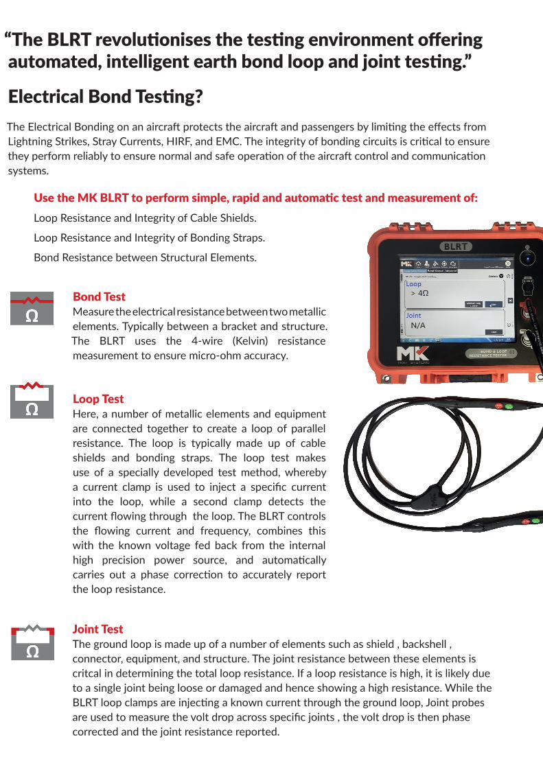
“The BLRT revolutionises the testing environment offering automated, intelligent earth bond loop and joint testing.”
Electrical Bond Testing? The Electrical Bonding on an aircraft protects the aircraft and passengers by limiting the effects from Lightning Strikes, Stray Currents, HIRF, and EMC. The integrity of bonding circuits is critical to ensure they perform reliably to ensure normal and safe operation of the aircraft control and communication systems.
Use the MK BLRT to perform simple, rapid and automatic test and measurement of: Loop Resistance and Integrity of Cable Shields.
Loop Resistance and Integrity of Bonding Straps.
Bond Resistance between Structural Elements.
Bond Test Measure the electrical resistance between two metallic elements. Typically between a bracket and structure. The BLRT uses the 4-wire (Kelvin) resistance measurement to ensure micro-ohm accuracy.
Loop Test Here, a number of metallic elements and equipment are connected together to create a loop of parallel resistance. The loop is typically made up of cable shields and bonding straps. The loop test makes use of a specially developed test method, whereby a current clamp is used to inject a specific current into the loop, while a second clamp detects the current flowing through the loop. The BLRT controls the flowing current and frequency, combines this with the known voltage fed back from the internal high precision power source, and automatically carries out a phase correction to accurately report the loop resistance.
Joint Test The ground loop is made up of a number of elements such as shield , backshell , connector, equipment, and structure. The joint resistance between these elements is critcal in determining the total loop resistance. If a loop resistance is high, it is likely due to a single joint being loose or damaged and hence showing a high resistance. While the BLRT loop clamps are injecting a known current through the ground loop, Joint probes are used to measure the volt drop across specific joints , the volt drop is then phase corrected and the joint resistance reported.
BLRT Features and Benefits
Lightweight and Robust• Single operator use• Battery powered and truly portable• Weight <7Kg• Size 35cm x 30cm x 15cm
Automatic• Integrated Computer complete with MK BLRT
Software • Automate the test process, saving time and
gaining efficiency• Paperless process• On screen graphical Operator guidance• Simple Touchscreen control• User Login and Access control• Automatic Pass and Fail of measured value• Automatic logging and upload of test results• Guarantees Traceability by User, UUT,
Measured result
Active Probes and Clamps• Push button control enables full test control
from the probes and loop clamps• LED pass fail indication on probes and loop
clamps improves test efficiency• Integrated lights on probes for testing in
dark areas• Various probe and clamp formats and
sizes available
Reliable and Accurate• Integrated Self Test and Validation toolset• Automatical validates system performance
during test and after clamp or probe change
Application and Benefit example A leading Aircraft Engine manufacturer had the following test process issues:
SituationEngineers testing in different ways- impacting test result conformityTesting taking too longManual (pen and paper) data capture introducing test data errorsFull traceability not in placeSolutionEnsured all engineers test in the same way, through on-screen test guide.Reduced a 2 engineer process to a single engineer and reduce testing times by 80%Automates test result data capture and uploads test results on completion.Ensures full traceability and test data integrity.Test Required 171 Loop Resistance measurements692 Joint Resistance measurements82 Bond Resistance measurementsResult: 32 man hour testing time reduced to 4 hours
For local Sales and Support contacts worldwide www.mktest.com
MK Test Systems Ltd (UK) Orchard Court. West Buckland. Taunton TA21 9LE England
• Carrying handle and optional harness • Soft-start current source prevents arcing• On-screen instructions • Auto and manual modes • Wireless data upload & download
• USB port (when data adapter fitted)• Network Port (when data adapter fitted)• Active Probes & Clamps- no need to touch the screen• Pass Fail Status indication on Probes and Clamps
BOND TEST MEASUREMENT (DC)- OPTION- Only applies when fittedCurrent (DC) up to 10A (10% accuracy)Resistance Range 0.2mΩ to 2ΩResistance resolution 0.1mΩResistance Accuracy ±(1% of reading ±0.2mΩ) @ 10ALOOP TEST MEASUREMENT Range 1 Range 2 Range 3 Range 4Mode 1 Arms (constant current) 1 Arms (constant current) 0.2 Vrms (constant voltage) 0.2 Vrms (constant voltage)Frequency 1kHz 1kHz 1kHz 1kHzLoop Resistance Range 1mΩ to 50mΩ 51mΩ to 200mΩ 201mΩ to 2000mΩ 2001mΩ to 4000mΩResistance Resolution 0.1mΩ 0.1mΩ 0.1mΩ 0.1mΩResistance Accuracy ±(2% of reading +0.5mΩ) ±(2% of reading +0.5mΩ) ±(5% of reading +0.5mΩ) ±(10% of reading +0.5mΩ)JOINT TEST MEASUREMENT Range 1 Range 2 Range 3 Range 4Mode 1Arms (constant current) 1Arms (constant current) 0.2 Vrms (constant voltage) 0.2 Vrms (constant voltage)Frequency 1kHz 1kHz 1kHz 1kHzApplied Loop Resistance Range 1mΩ to 50mΩ 51mΩ to 200mΩ 201mΩ to 2000mΩ 2001mΩ to 4000mΩJoint Resistance Range 0.5mΩ to 50mΩ 0.05mΩ* (@51mΩ Loop) to 200mΩ 0.50mΩ* (@201mΩ Loop) to 2000mΩ 5.00mΩ* (@2001mΩ Loop) to 4000mΩResistance Resolution 0.01mΩ 0.01mΩ 0.01mΩ 0.01mΩResistance Accuracy ±(5% of reading +0.5mΩ) ±(5% of reading +0.25% of loop) ±(5% of reading +0.25% of loop) ±(10% of reading +0.25% of loop)
*To determine lowest measurable joint resistance for a given loop use: Joint(low)= Loop resistance x Percentage shown
LOW JOINT INDICATIONMode Autoranging (max 1Arms)Frequency 200HzApplied Loop Resistance Range 0.5mΩ to 40mΩJoint resistance Range up to 0.05mΩResistance Resolution n/aResistance Accuracy System reports “<0.05mΩ” for measurable joints below 0.05mΩ