20
AUXILIARY VIEWS Technical Drawing Stuarts Draft High School
| Date post: | 18-Dec-2015 |
| Category: |
Documents |
| Upload: | tracey-pearson |
| View: | 281 times |
| Download: | 3 times |
AUXILIARY VIEWS
Technical DrawingStuarts Draft High
School
Introduction
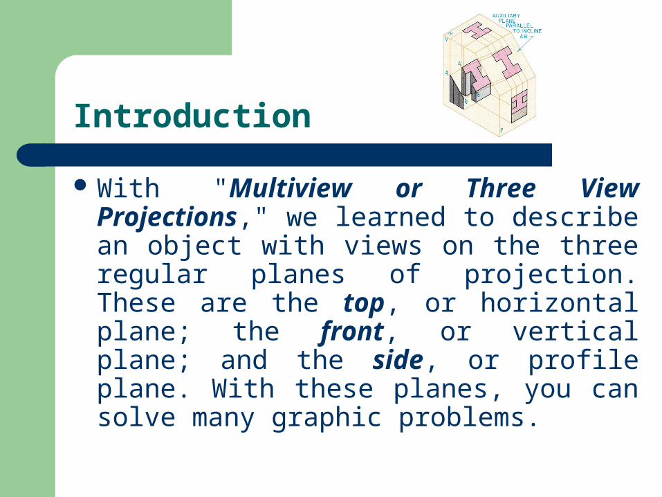
With "Multiview or Three View Projections," we learned to describe an object with views on the three regular planes of projection. These are the top, or horizontal plane; the front, or vertical plane; and the side, or profile plane. With these planes, you can solve many graphic problems.
Introduction (Con’t)
However, to solve problems involving inclined (slanted) surfaces, you will need to learn to draw views on auxiliary (additional) planes of projection. These are called auxiliary views. In this lesson we will explore how to draw these views on planes that are parallel to the inclined surfaces.
AUXILIARY VIEWS ARE "HELPER VIEWS"
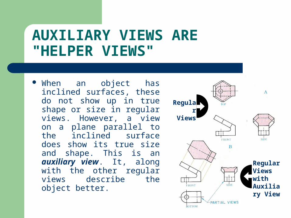
When an object has inclined surfaces, these do not show up in true shape or size in regular views. However, a view on a plane parallel to the inclined surface does show its true size and shape. This is an auxiliary view. It, along with the other regular views describe the object better.
Regular
Views
Regular Views with Auxiliary View
Why Do We Use Them?
An auxiliary view is a projection on an auxiliary plane that is parallel to an inclined (slanting) surface.
It is a view looking directly at the inclined surface in a direction perpendicular to it.
Auxiliary projections are important for describing the true geometric shapes of inclined surfaces.
You also use them for dimensioning these shapes.
Why Do We Use Them?
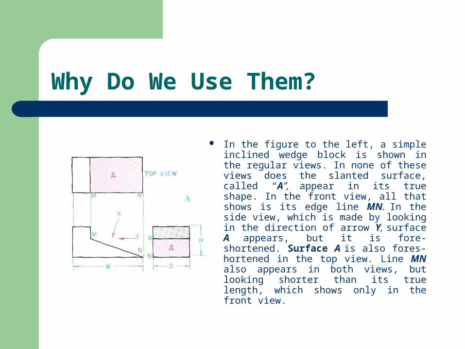
In the figure to the left, a simple inclined wedge block is shown in the regular views. In none of these views does the slanted surface, called “A”, appear in its true shape. In the front view, all that shows is its edge line MN. In the side view, which is made by looking in the direction of arrow Y, surface A appears, but it is fore-shortened. Surface A is also fores-hortened in the top view. Line MN also appears in both views, but looking shorter than its true length, which shows only in the front view.
THE RELATIONSHIP OF AUXILIARY VIEWS TO REGULAR VIEWS
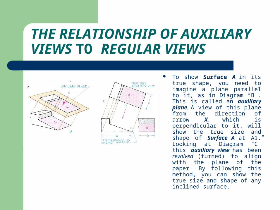
To show Surface A in its true shape, you need to imagine a plane parallel to it, as in Diagram “B”. This is called an auxiliary plane. A view of this plane from the direction of arrow X, which is perpendicular to it, will show the true size and shape of Surface A at A1. Looking at Diagram “C” this auxiliary view has been revolved (turned) to align with the plane of the paper. By following this method, you can show the true size and shape of any inclined surface.
Step by Step Directions for Making Auxiliary Views
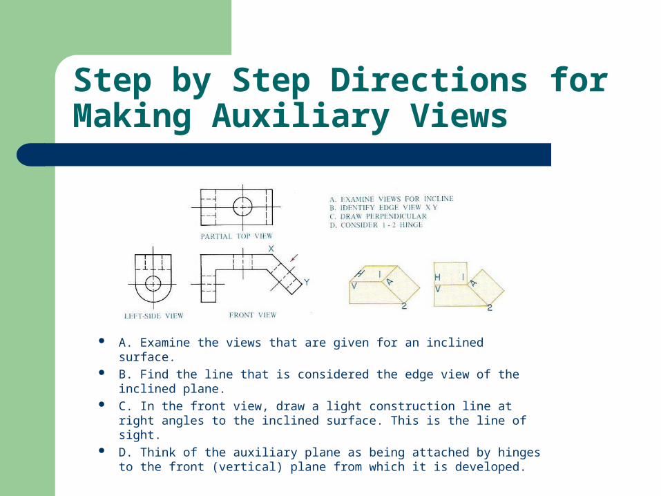
A. Examine the views that are given for an inclined surface. B. Find the line that is considered the edge view of the inclined
plane. C. In the front view, draw a light construction line at right angles
to the inclined surface. This is the line of sight. D. Think of the auxiliary plane as being attached by hinges to the
front (vertical) plane from which it is developed.
Step by Step Directions for Making Auxiliary Views
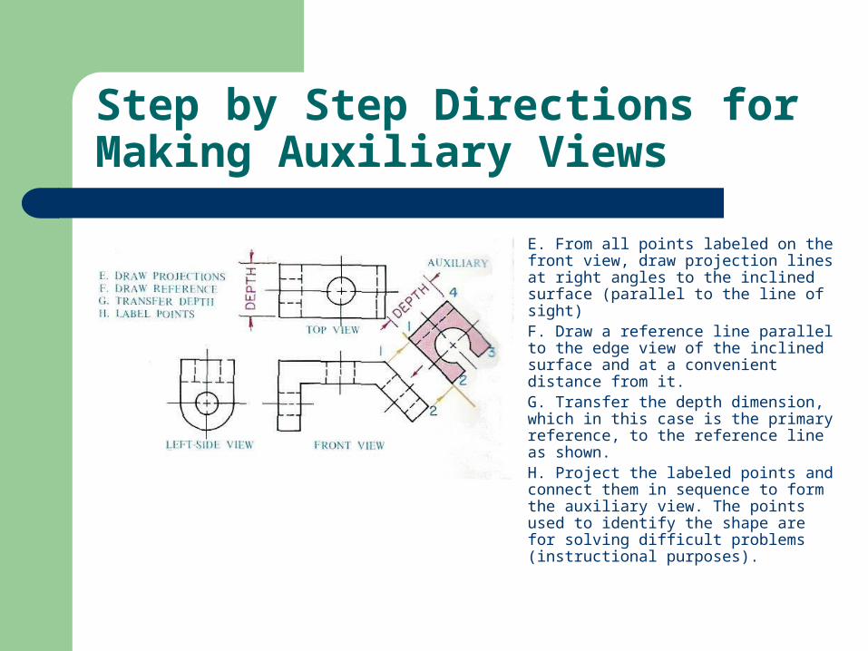
E. From all points labeled on the front view, draw projection lines at right angles to the inclined surface (parallel to the line of sight)
F. Draw a reference line parallel to the edge view of the inclined surface and at a convenient distance from it.
G. Transfer the depth dimension, which in this case is the primary reference, to the reference line as shown.
H. Project the labeled points and connect them in sequence to form the auxiliary view. The points used to identify the shape are for solving difficult problems (instructional purposes).
How to Draw an Auxiliary View Using the Center Plane Reference
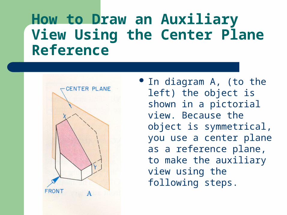
In diagram A, (to the left) the object is shown in a pictorial view. Because the object is symmetrical, you use a center plane as a reference plane, to make the auxiliary view using the following steps.
How to Draw an Auxiliary View Using the Center Plane Reference
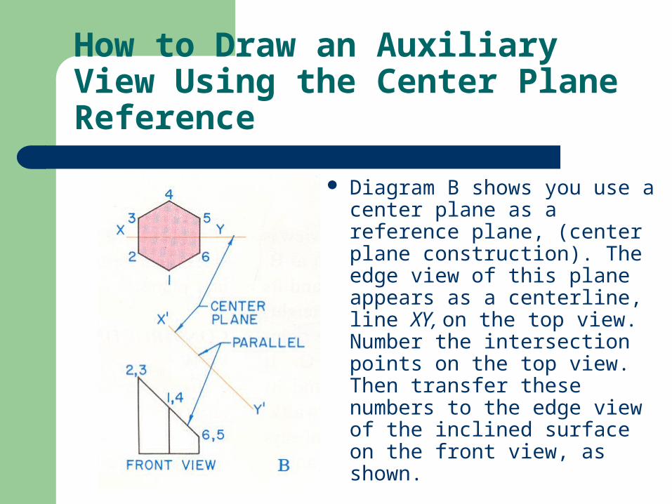
Diagram B shows you use a center plane as a reference plane, (center plane construction). The edge view of this plane appears as a centerline, line XY, on the top view. Number the intersection points on the top view. Then transfer these numbers to the edge view of the inclined surface on the front view, as shown.
How to Draw an Auxiliary View Using the Center Plane Reference
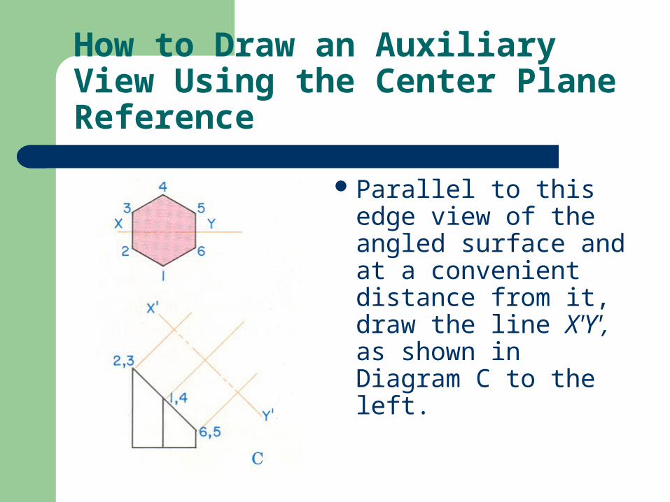
Parallel to this edge view of the angled surface and at a convenient distance from it, draw the line X'Y', as shown in Diagram C to the left.
How to Draw an Auxiliary View Using the Center Plane Reference
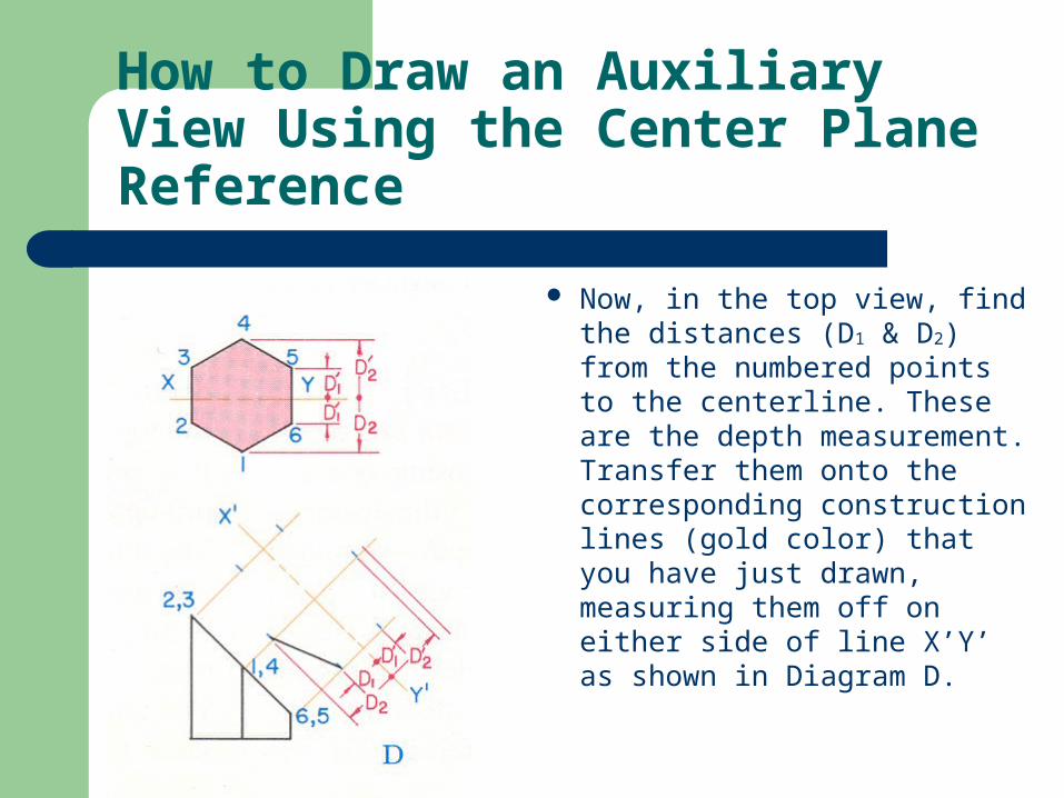
Now, in the top view, find the distances (D1 & D2) from the numbered points to the centerline. These are the depth measurement. Transfer them onto the corresponding construction lines (gold color) that you have just drawn, measuring them off on either side of line X’Y’ as shown in Diagram D.
How to Draw an Auxiliary View Using the Center Plane Reference
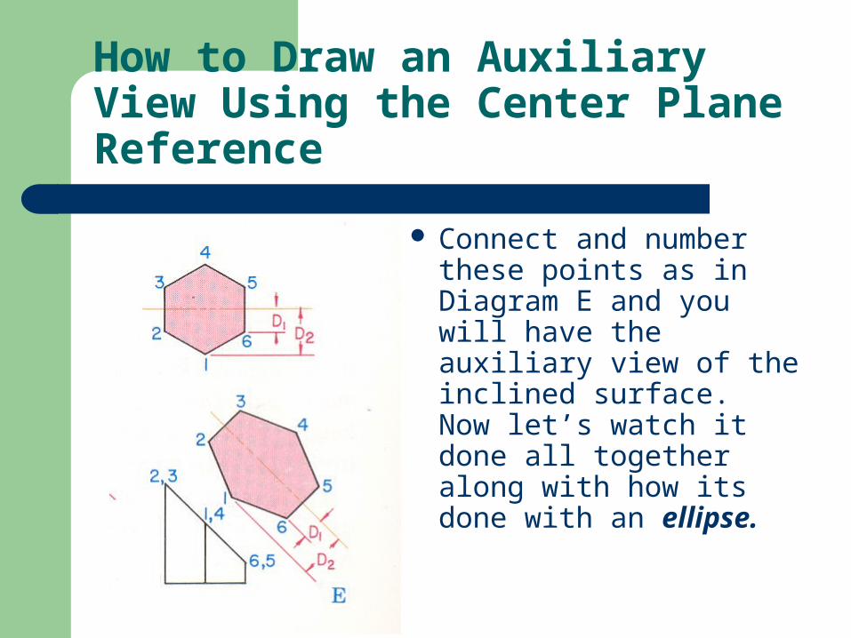
Connect and number these points as in Diagram E and you will have the auxiliary view of the inclined surface. Now let’s watch it done all together along with how its done with an ellipse.
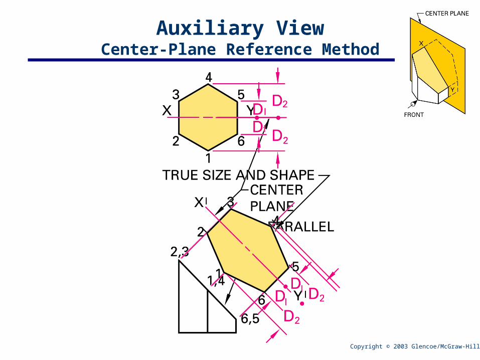
Auxiliary ViewCenter-Plane Reference Method
Copyright © 2003 Glencoe/McGraw-Hill
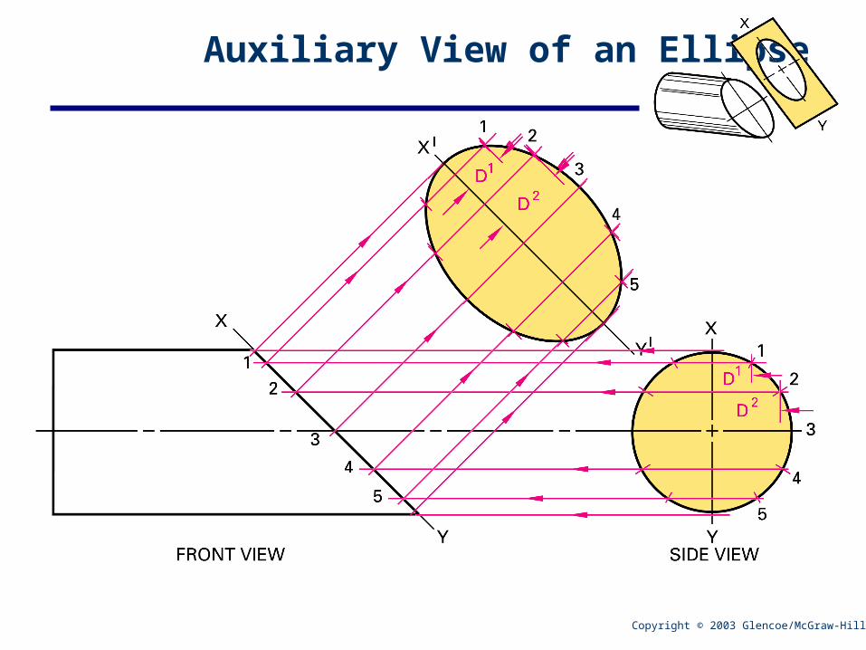
Auxiliary View of an Ellipse
Copyright © 2003 Glencoe/McGraw-Hill
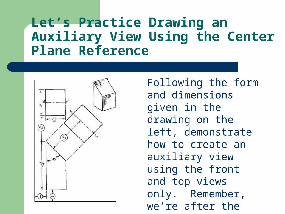
Let’s Practice Drawing an Auxiliary View Using the Center Plane Reference
Following the form and dimensions given in the drawing on the left, demonstrate how to create an auxiliary view using the front and top views only. Remember, we’re after the true size and shape of the inclined surface.
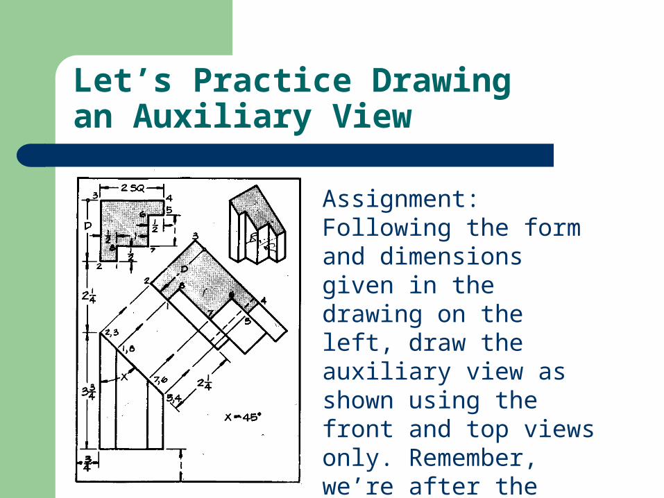
Let’s Practice Drawing an Auxiliary View
Assignment: Following the form and dimensions given in the drawing on the left, draw the auxiliary view as shown using the front and top views only. Remember, we’re after the true size and shape of the inclined surface (the shaded area).
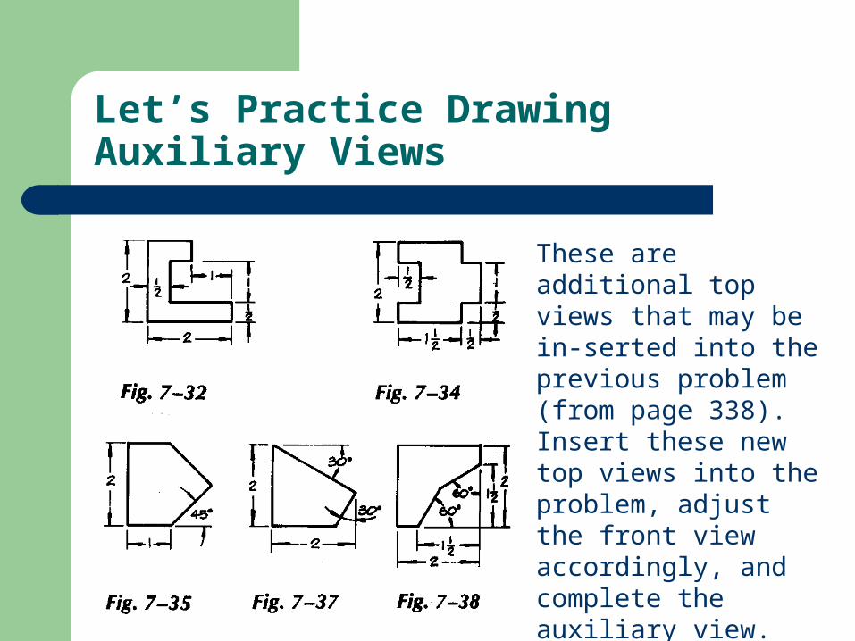
Let’s Practice Drawing Auxiliary Views
These are additional top views that may be in-serted into the previous problem (from page 338). Insert these new top views into the problem, adjust the front view accordingly, and complete the auxiliary view. Do two drawings per paper (front & back.)
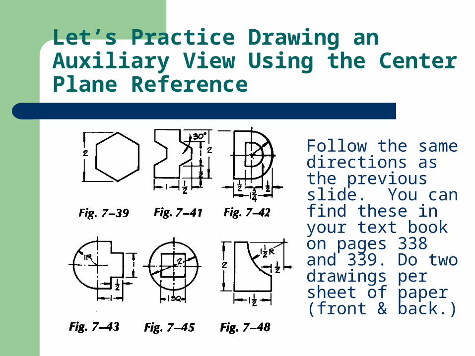
Let’s Practice Drawing an Auxiliary View Using the Center Plane Reference
Follow the same directions as the previous slide. You can find these in your text book on pages 338 and 339. Do two drawings per sheet of paper (front & back.)


