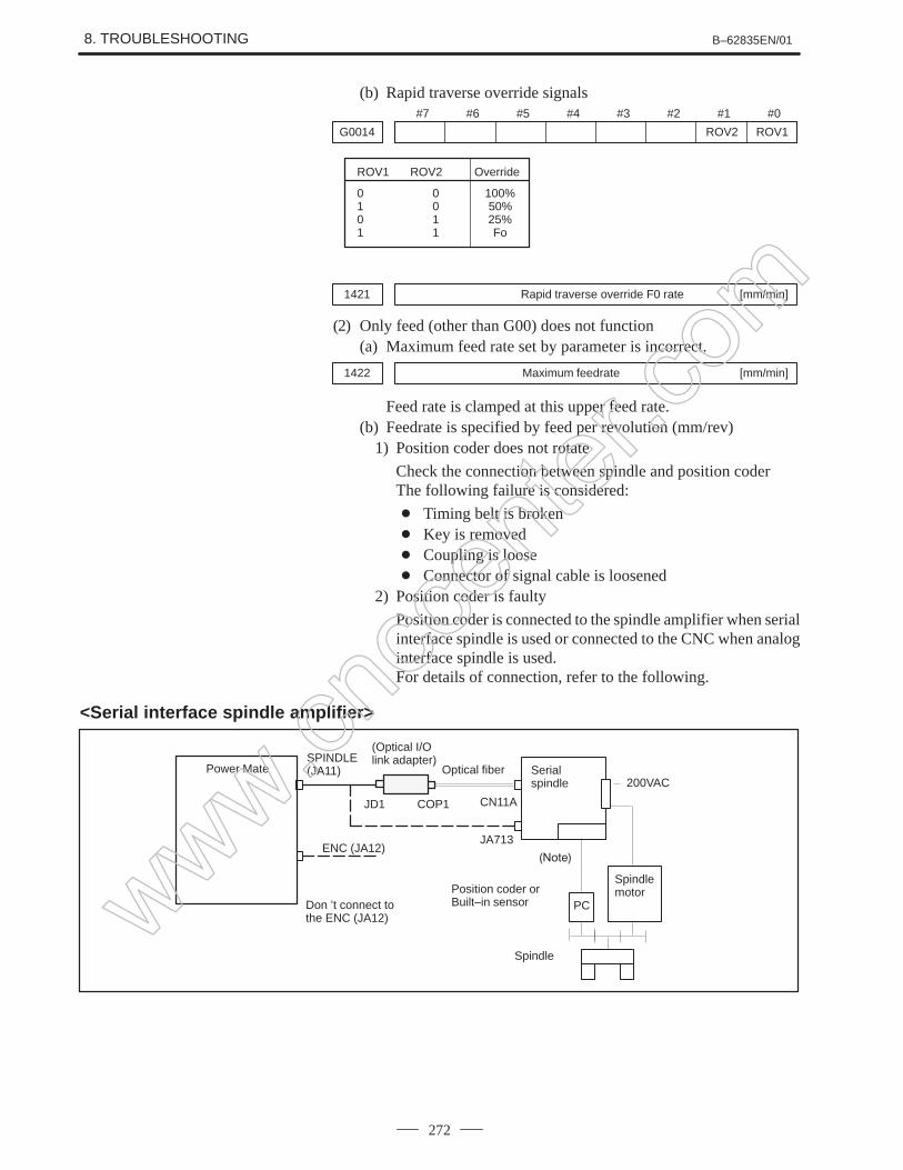
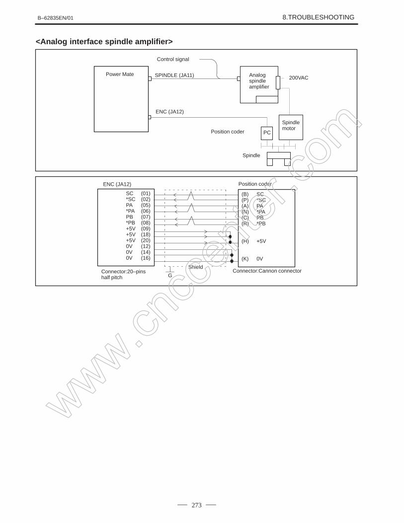
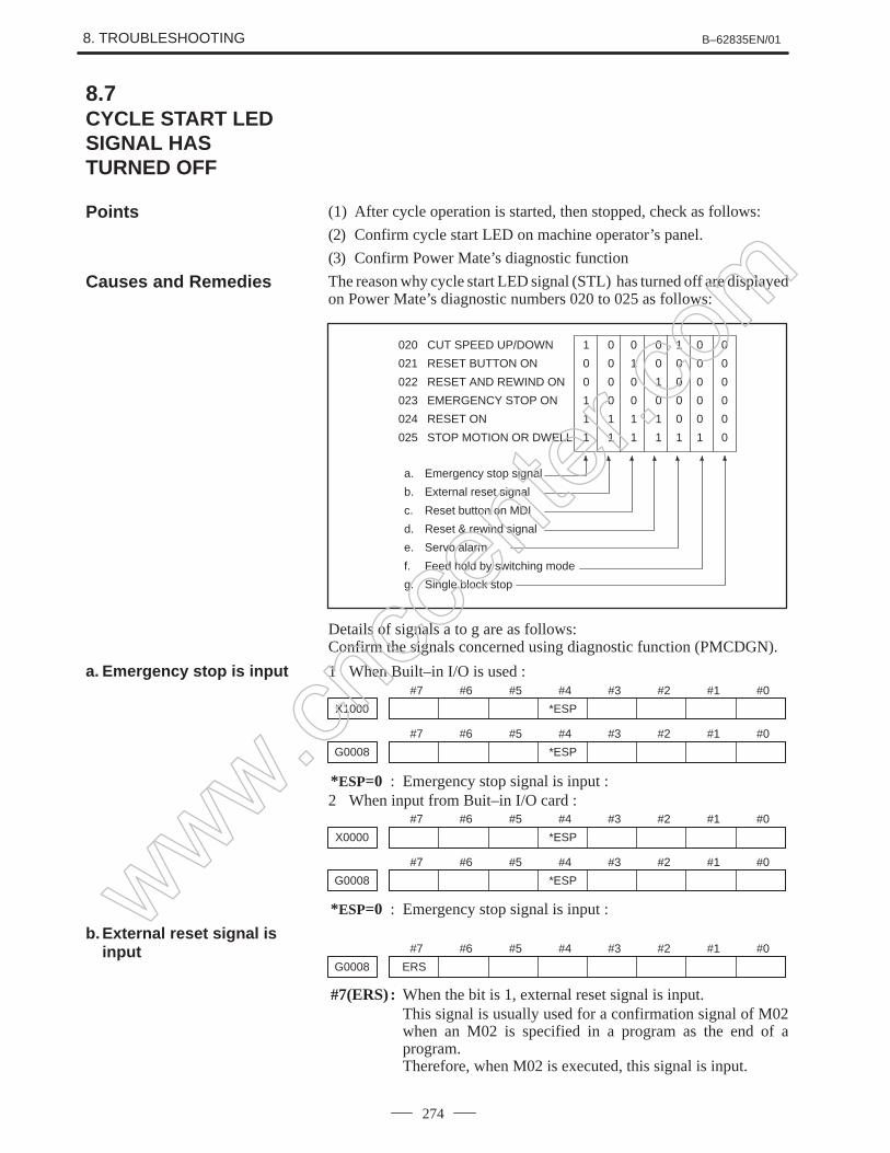
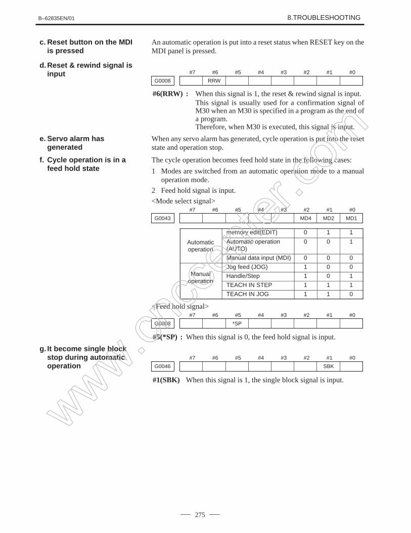
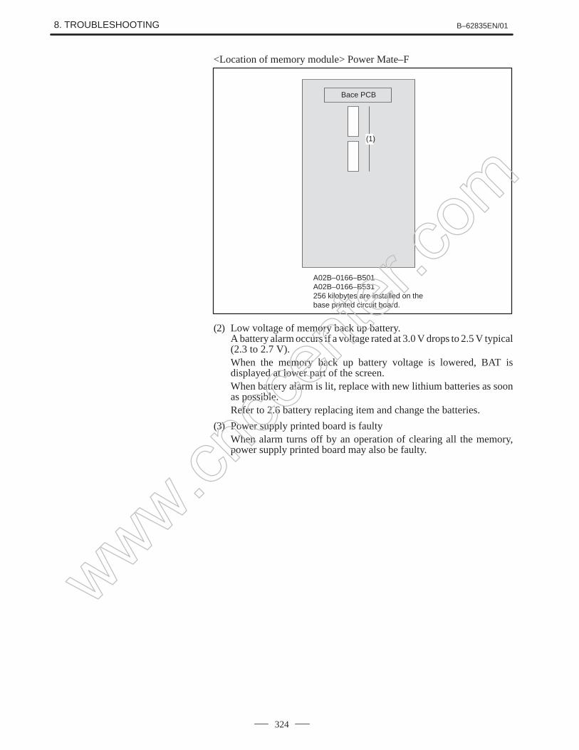
GFZ-62835EN B-62835EN GE Fanuc CNC Power Mate D and F Motion Controllers Maintenance Manual Presented By: CNC Center For Product Needs Please Visit: http://www.cnccenter.com/ OR Email: [email protected]OR Call: 1-800-963-3513 GE Fanuc CNC Manuals www.cnccenter.com
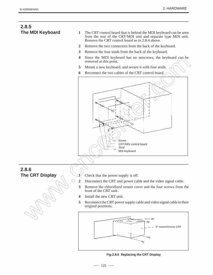
Transcript
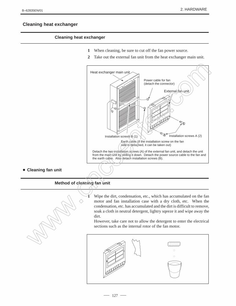
GFZ-62835EN B-62835EN
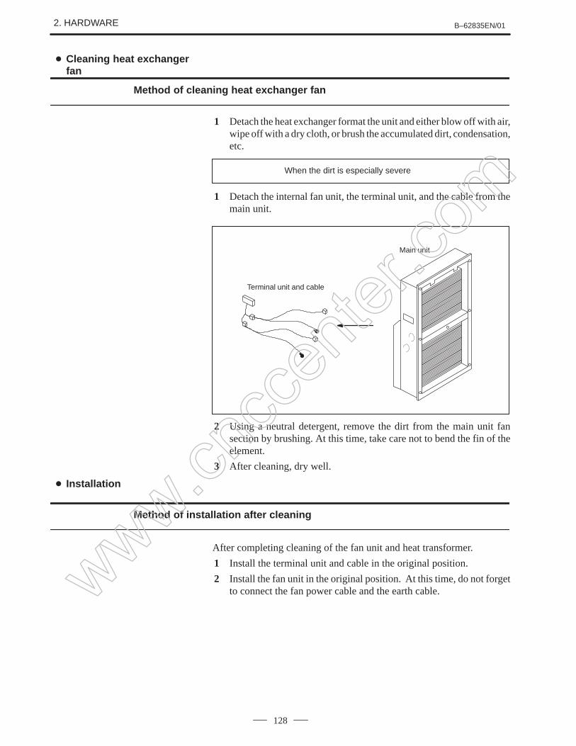
GE Fanuc CNC
Power Mate D and F Motion ControllersMaintenance Manual
B–62835EN/01 DEFINITION OF WARNING, CAUTION, AND NOTE
s–1
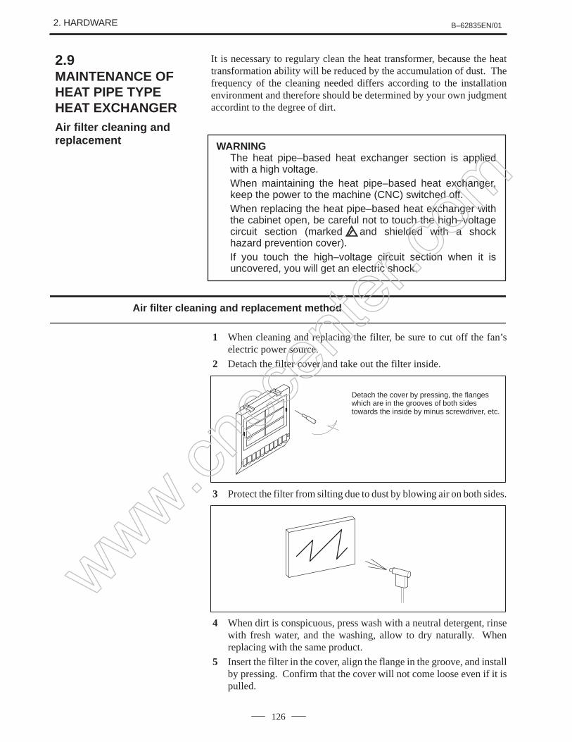
DEFINITION OF WARNING, CAUTION, AND NOTE
This manual includes safety precautions for protecting the user and preventing damage to themachine. Precautions are classified into Warning and Caution according to their bearing on safety.Also, supplementary information is described as a Note. Read the Warning, Caution, and Notethoroughly before attempting to use the machine.
WARNING
Applied when there is a danger of the user being injured or when there is a damage of both the userbeing injured and the equipment being damaged if the approved procedure is not observed.
CAUTION
Applied when there is a danger of the equipment being damaged, if the approved procedure is notobserved.
NOTE
The Note is used to indicate supplementary information other than Warning and Caution.
Read this manual carefully, and store it in a safe place.
B–62835EN/01 PREFACE
p–1
PREFACE
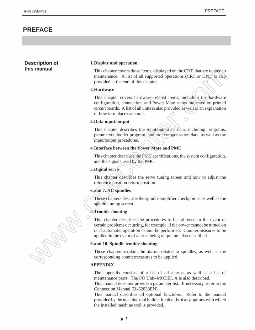
1.Display and operation
This chapter covers those items, displayed on the CRT, that are related tomaintenance. A list of all supported operations (CRT or DPL) is alsoprovided at the end of this chapter.
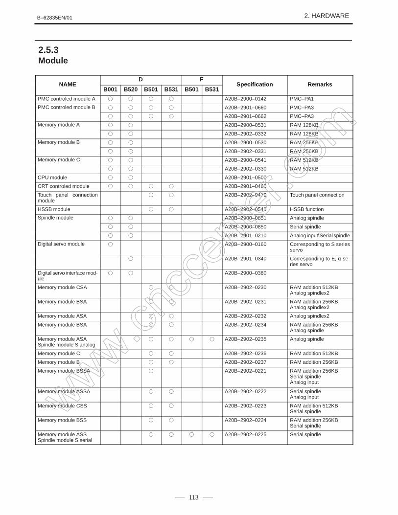
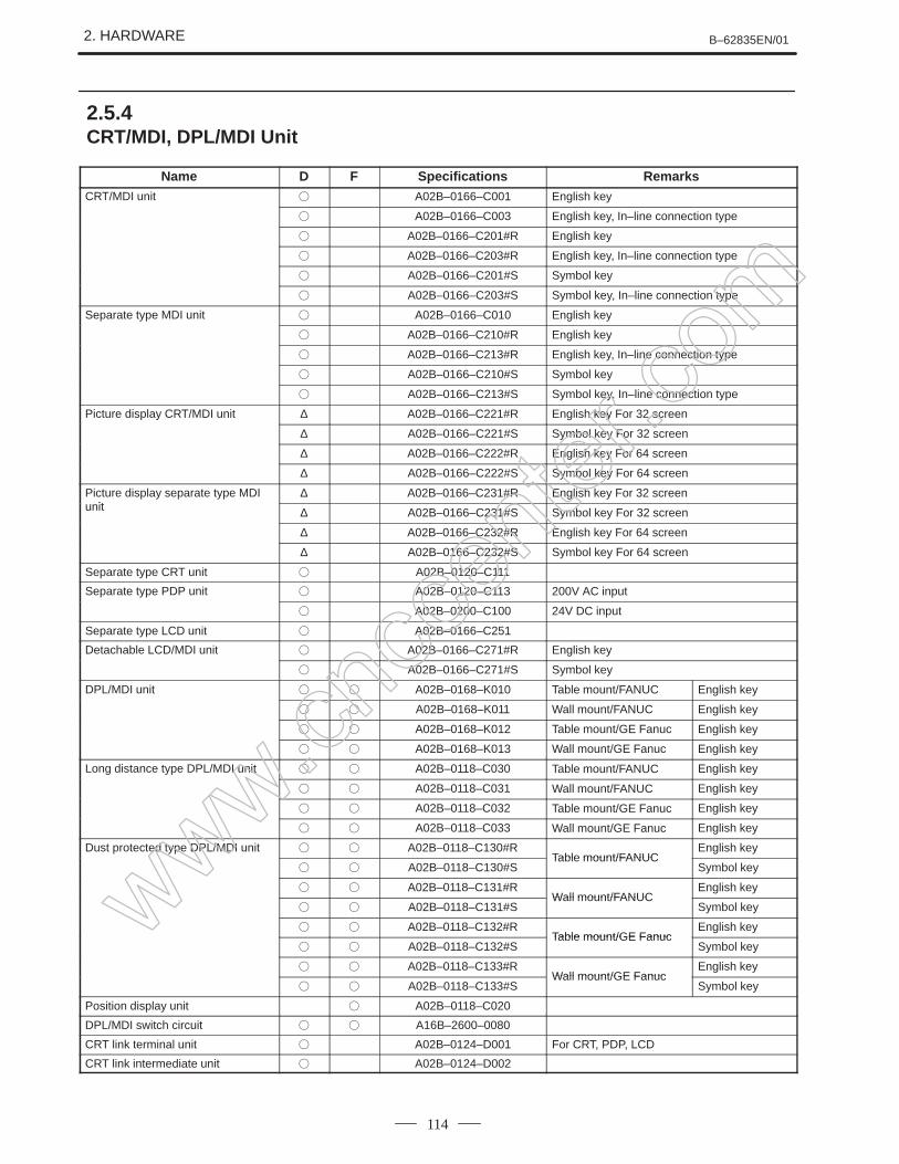
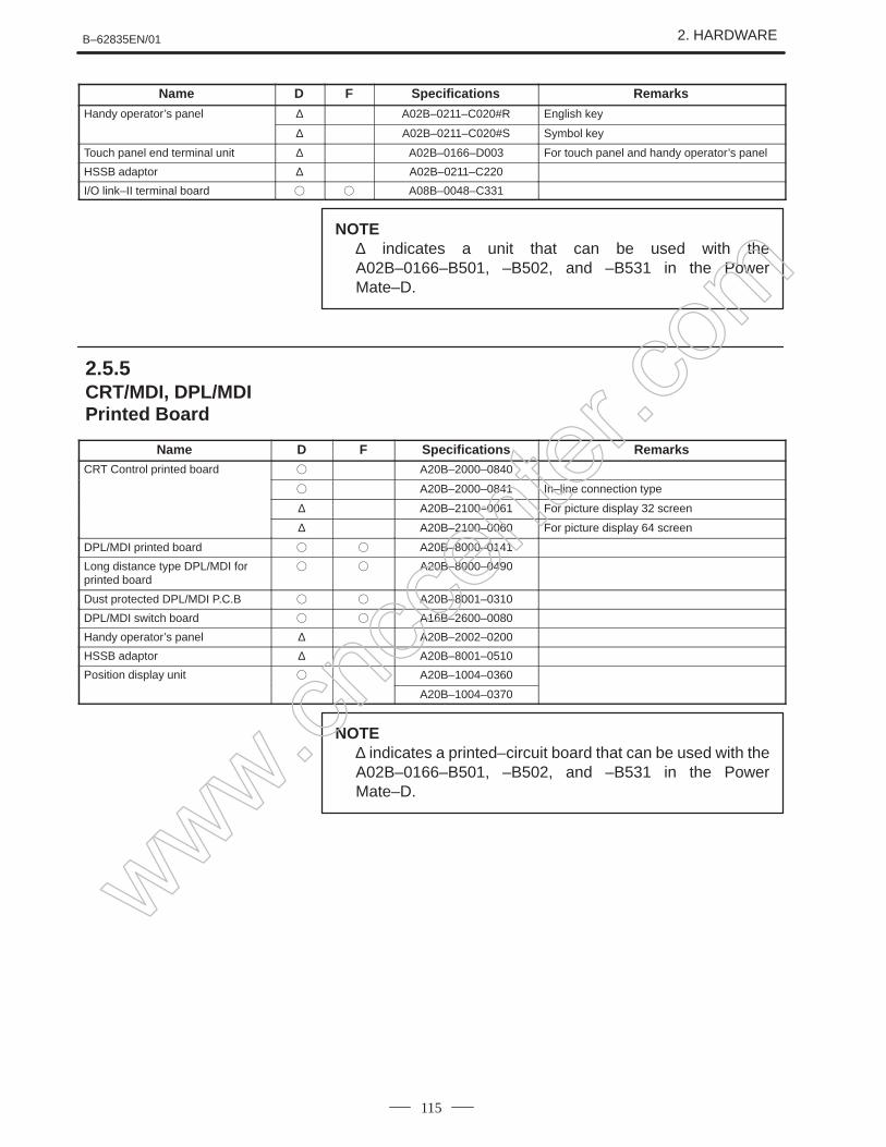
2.Hardware
This chapter covers hardware–related items, including the hardwareconfiguration, connection, and Power Mate status indicated on printedcircuit boards. A list of all units is also provided as well as an explanationof how to replace each unit.
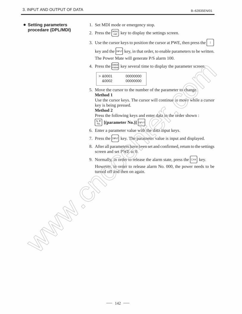
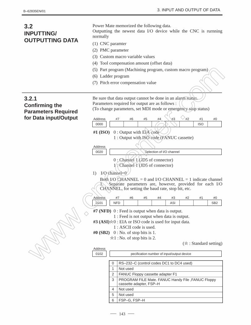
3.Data input/output
This chapter describes the input/output of data, including programs,parameters, lodder program, and tool compensation data, as well as theinput/output procedures.
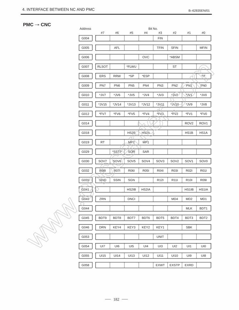
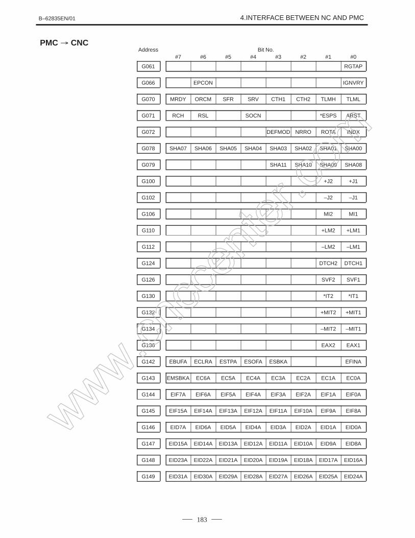
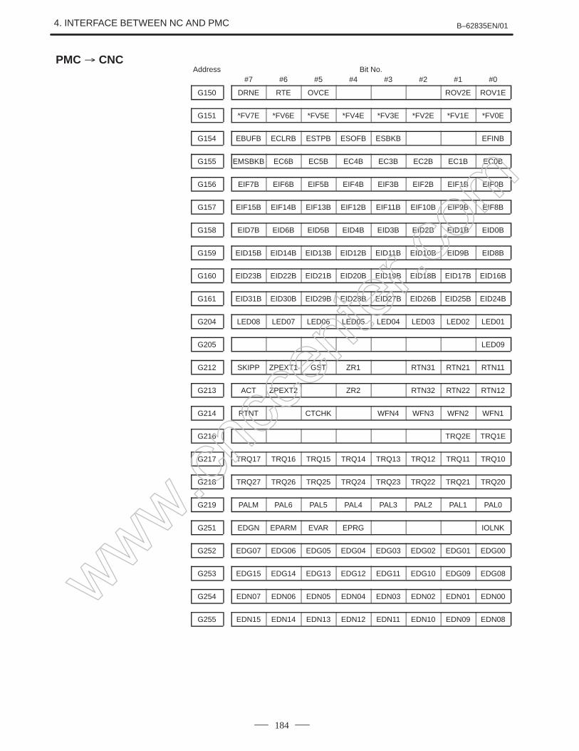
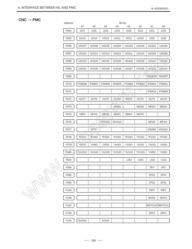
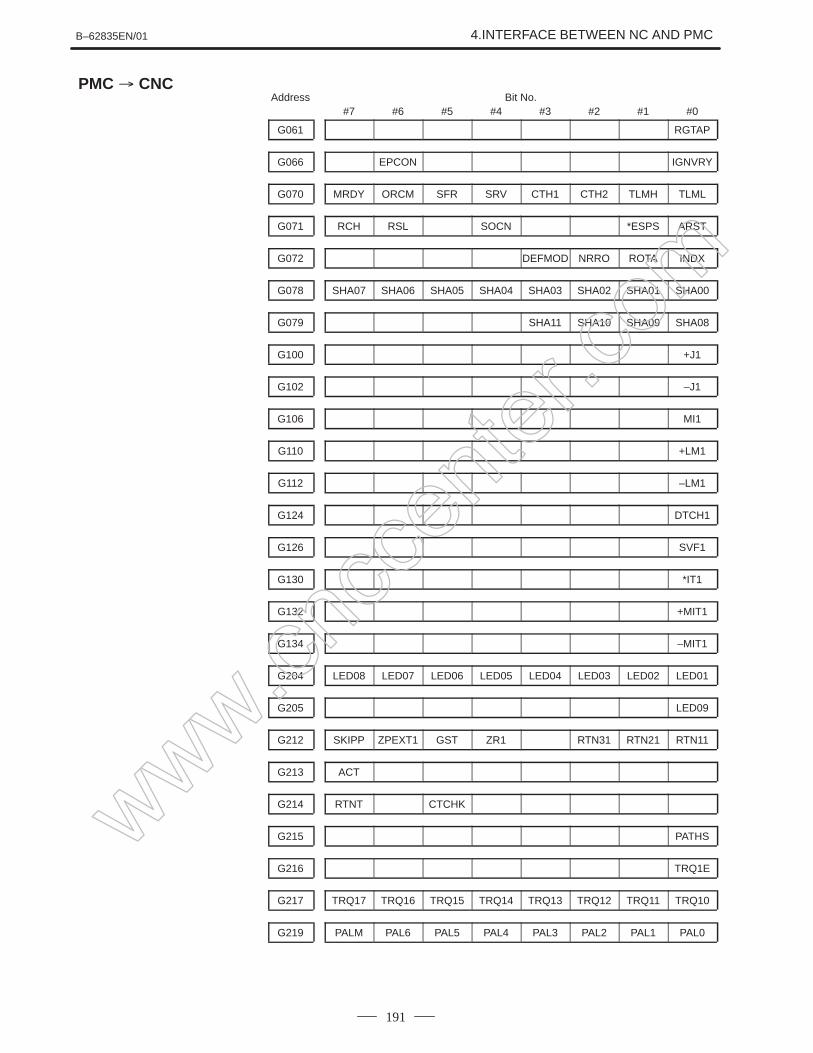
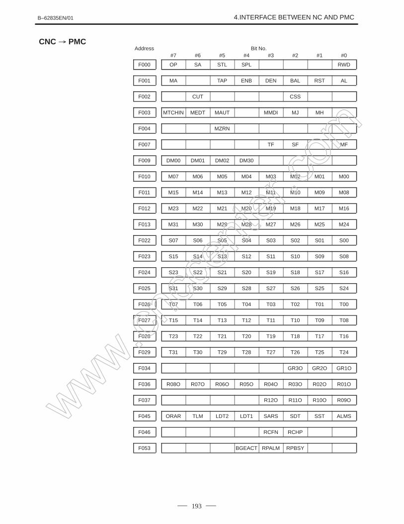
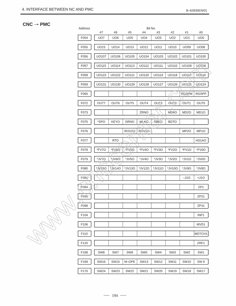
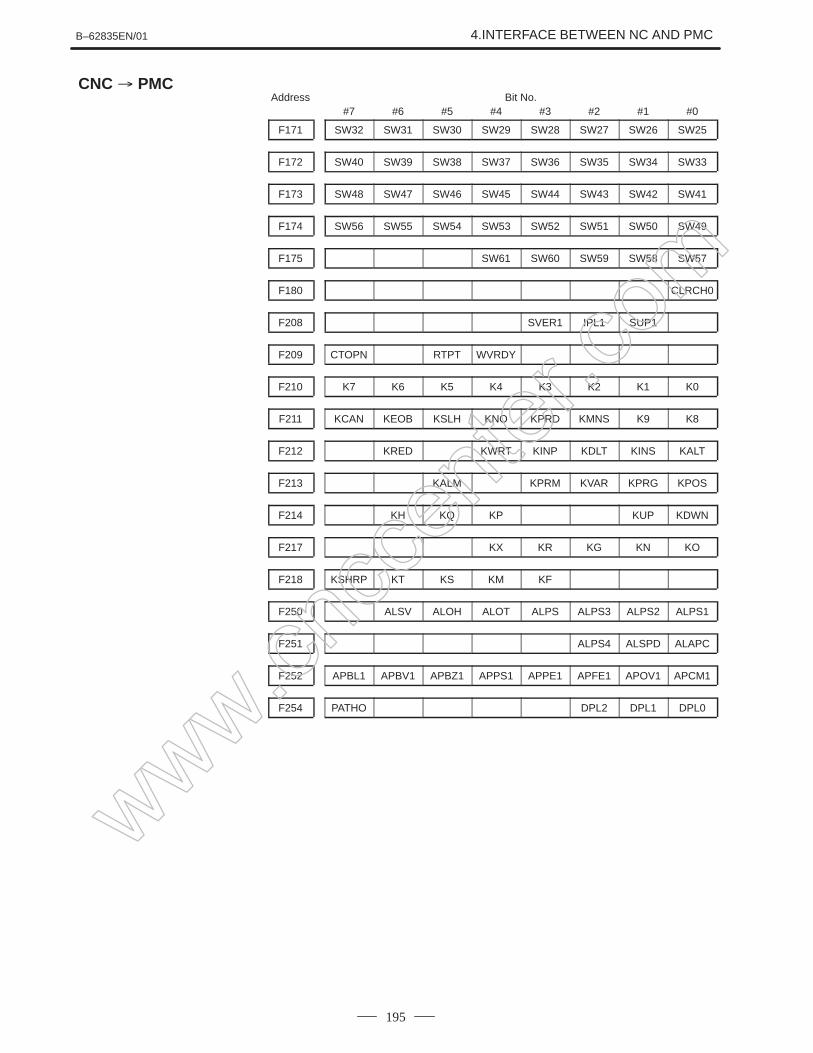
4.Interface between the Power Mate and PMC
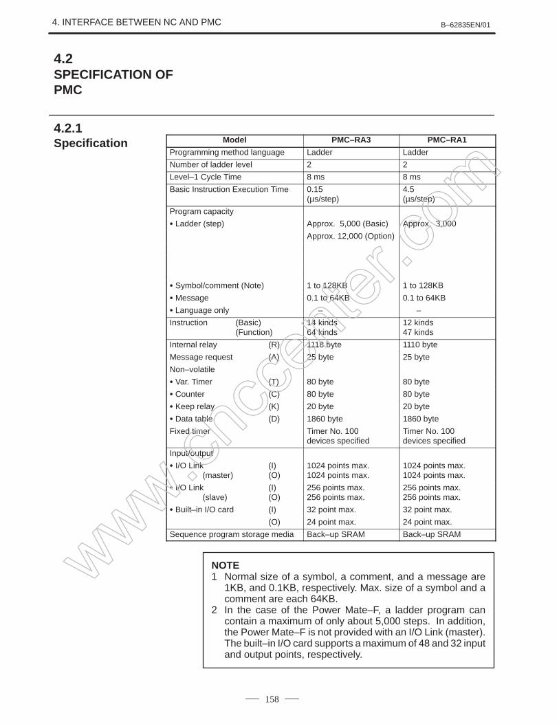
This chapter describes the PMC specifications, the system configuration,and the signals used by the PMC.
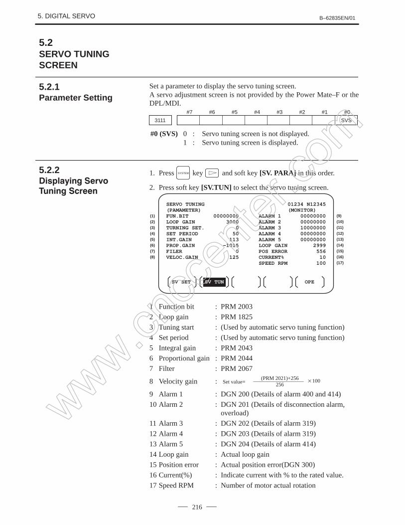
5.Digital servo
This chapter describes the servo tuning screen and how to adjust thereference position return position.
6.and 7. AC spindles
These chapters describe the spindle amplifier checkpoints, as well as thespindle tuning screen.
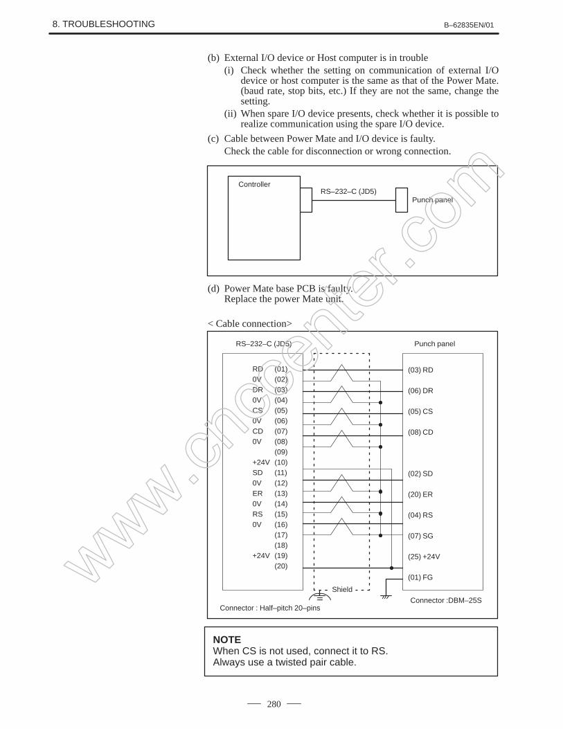
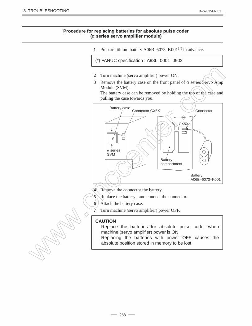
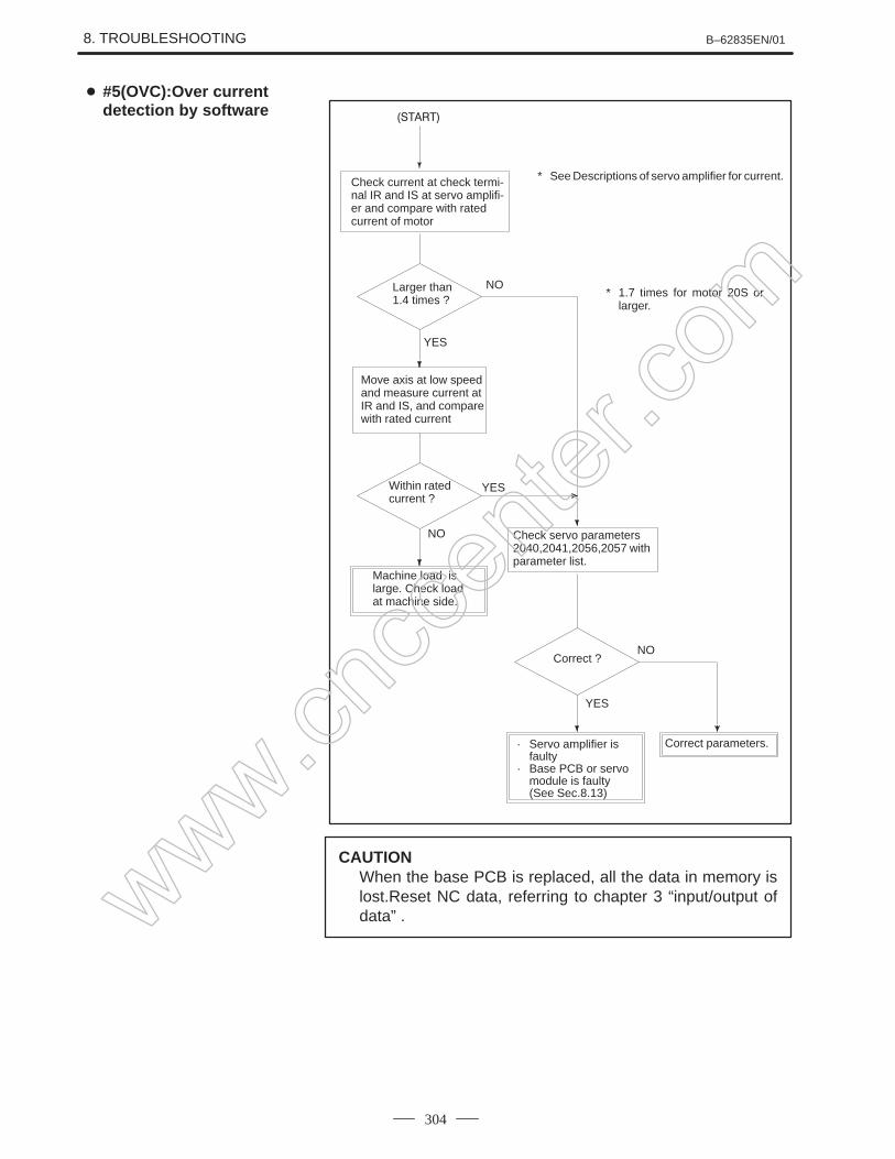
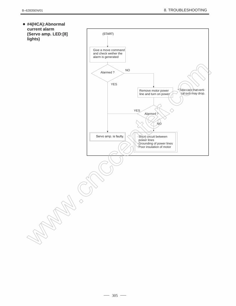
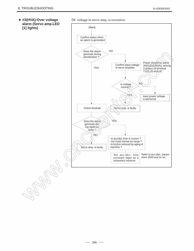
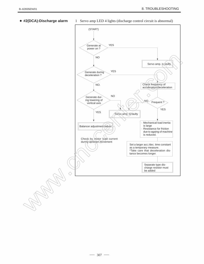
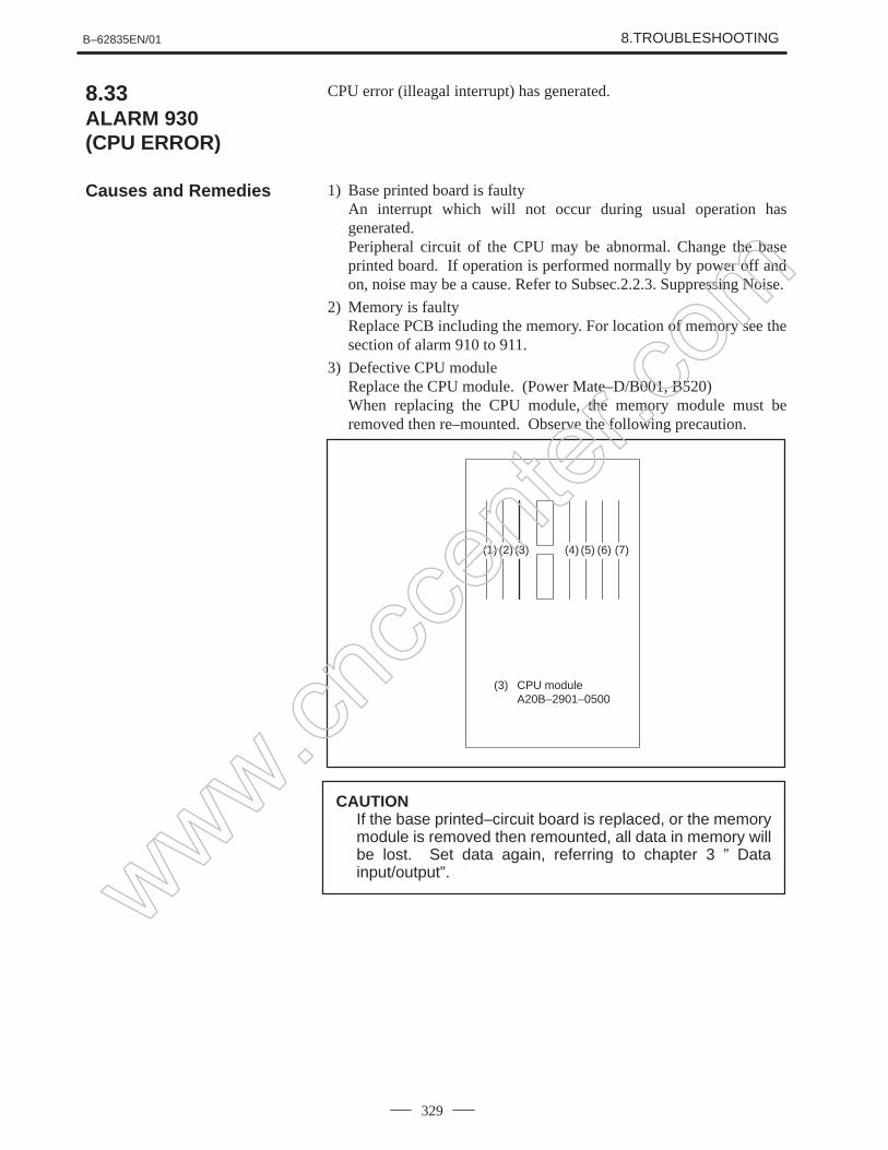
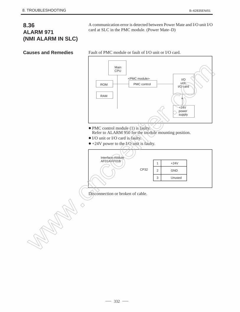
8.Trouble shooting
This chapter describes the procedures to be followed in the event ofcertain problems occurring, for example, if the power cannot be turned onor if automatic operation cannot be performed. Countermeasures to beapplied in the event of alarms being output are also described.
9.and 10. Spindle trouble shooting
These chapters explain the alarms related to spindles, as well as thecorresponding countermeasures to be applied.
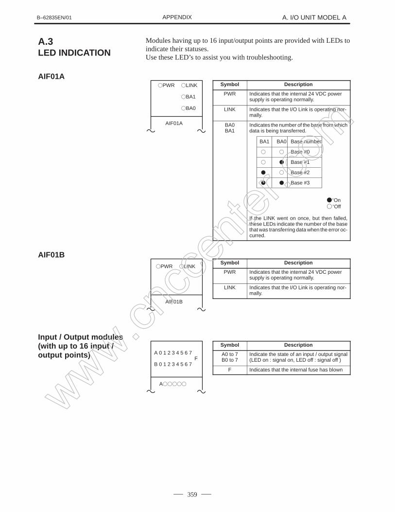
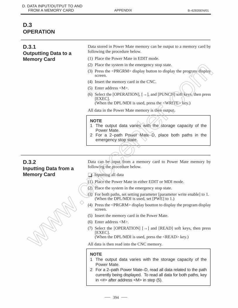
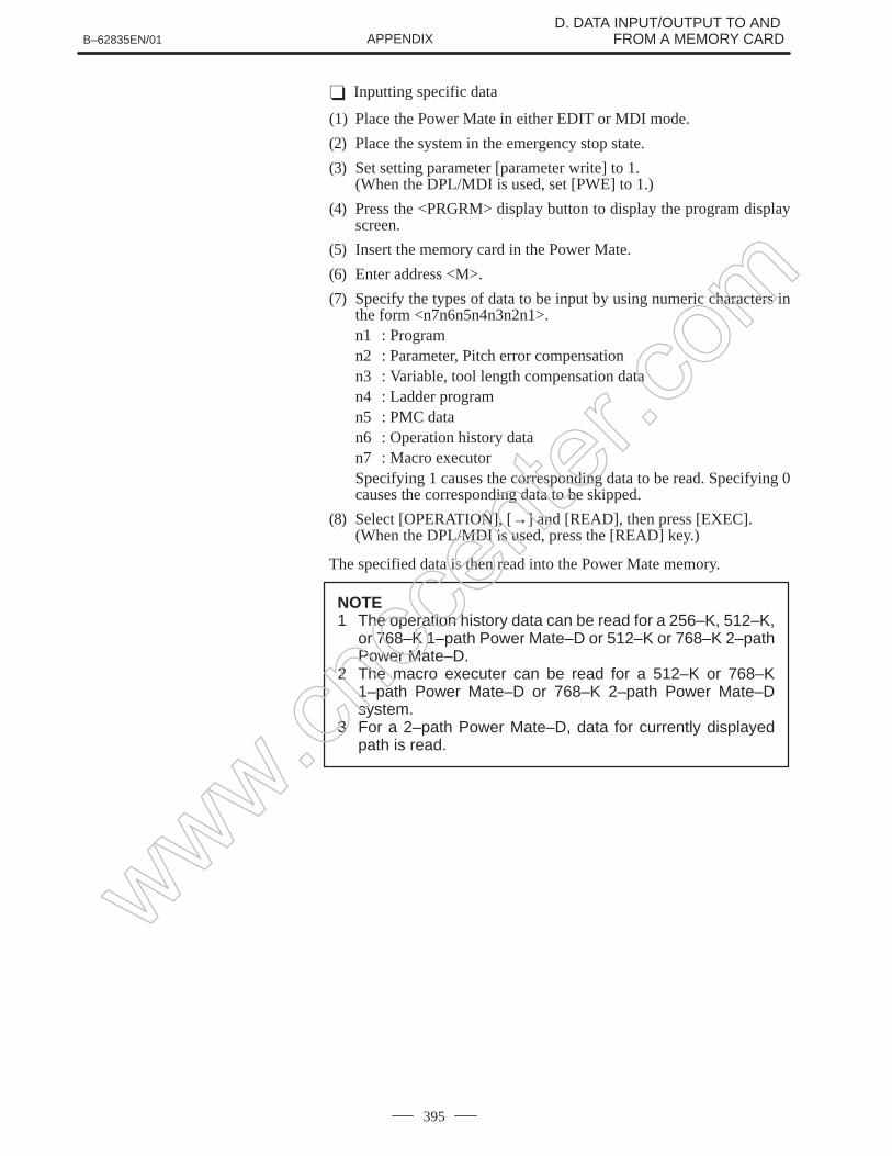
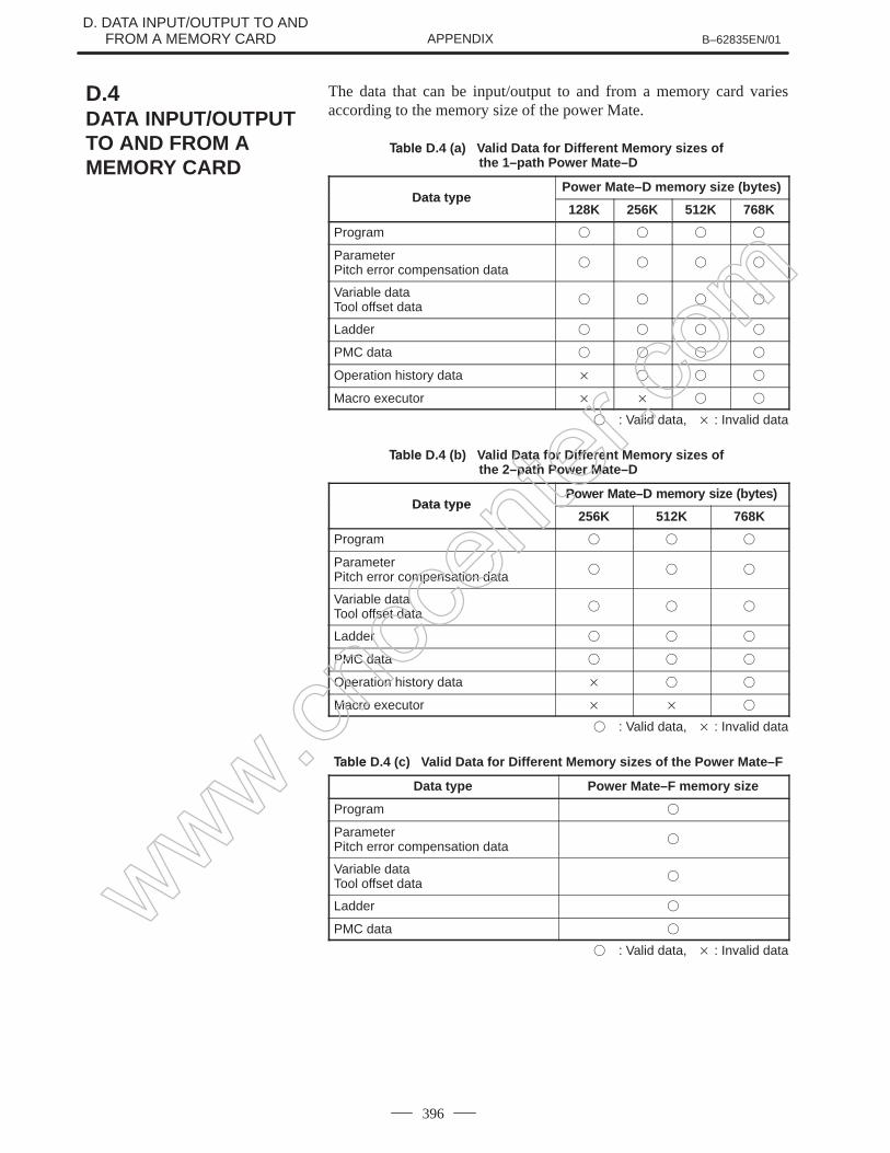
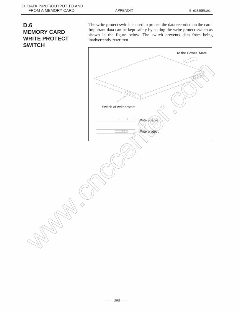
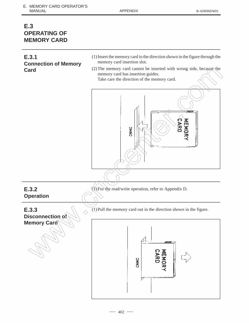
APPENDIX
The appendix consists of a list of all alarms, as well as a list ofmaintenance parts. The I/O Unit–MODEL A is also described.This manual does not provide a parameter list. If necessary, refer to theConnection Manual (B–62833EN).This manual describes all optional functions. Refer to the manualprovided by the machine tool builder for details of any options with whichthe installed machine tool is provided.
Description of this manual
www.cncc
enter
.com
PREFACE B–62835EN/01
p–2
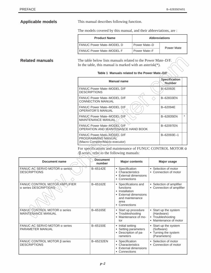
This manual describes following function.
The models covered by this manual, and their abbreviations, are :
Product Name Abbreviations
FANUC Power Mate–MODEL D Power Mate–DPower Mate
FANUC Power Mate–MODEL F Power Mate–FPower Mate
The table below lists manuals related to the Power Mate–D/F.In the table, this manual is marked with an asterisk(*).
1 Manuals related to the Power Mate–D/F
Manual name SpecificationNumber
FANUC Power Mate–MODEL D/FDESCRIPTIONS
B–62092E
FANUC Power Mate–MODEL D/FCONNECTION MANUAL
B–62833EN
FANUC Power Mate–MODEL D/FOPERATOR’S MANUAL
B–62094E
FANUC Power Mate–MODEL D/FMAINTENANCE MANUAL
B–62835EN *
FANUC Power Mate–MODEL D/FOPERATION AND MAINTENANCE HAND BOOK
B–62097EN
FANUC Power Mate–MODEL D/FPROGRAMMING MANUAL (Macro Compiler/Macro executor)
B–62093E–1
For specifications and maintenance of FUNUC CONTROL MOTOR α/β series, refer to the following manuals:
Document name Documentnumber Major contents Major usage
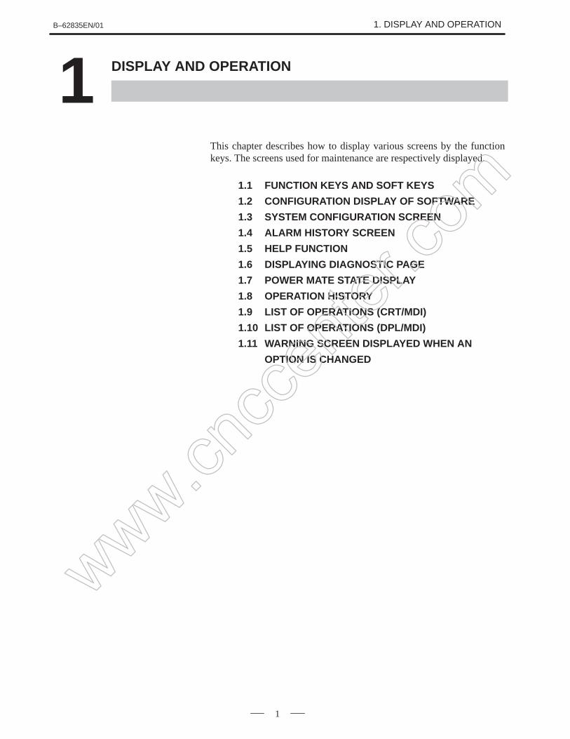
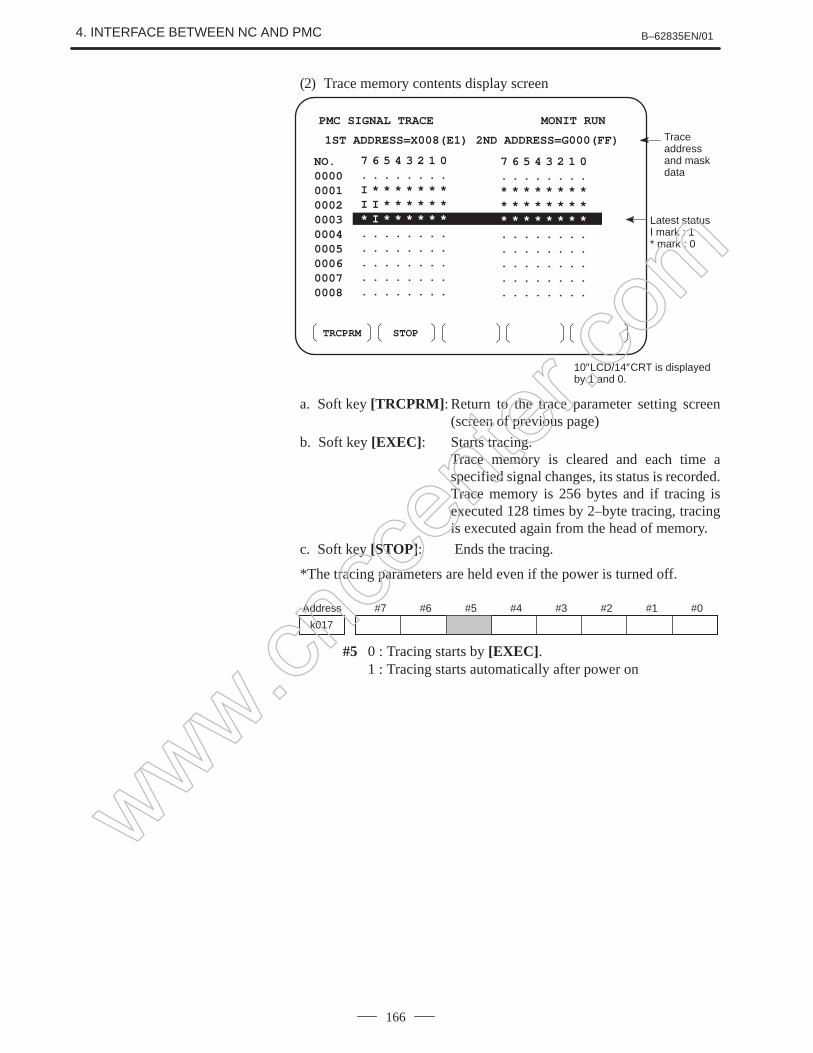
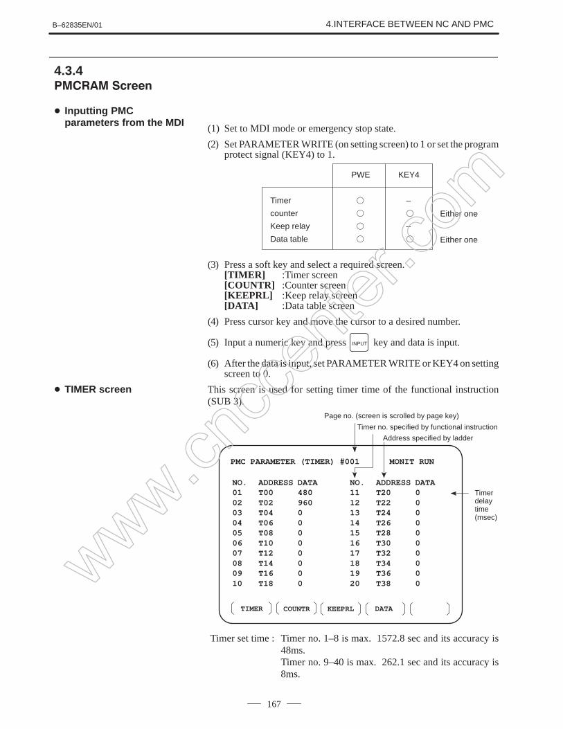
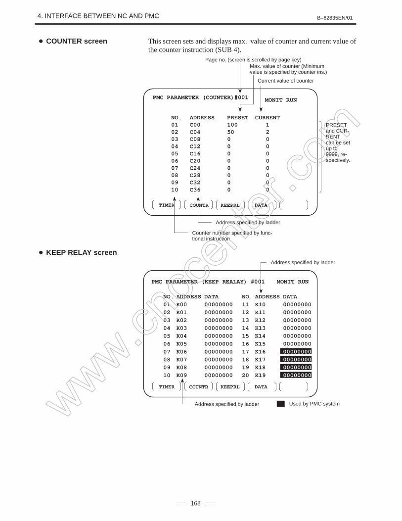
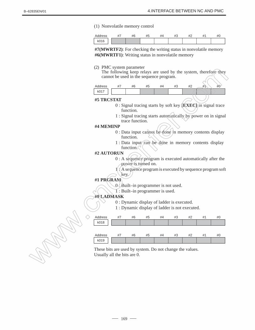
This chapter describes how to display various screens by the functionkeys. The screens used for maintenance are respectively displayed.
1.1 FUNCTION KEYS AND SOFT KEYS
1.2 CONFIGURATION DISPLAY OF SOFTWARE
1.3 SYSTEM CONFIGURATION SCREEN
1.4 ALARM HISTORY SCREEN
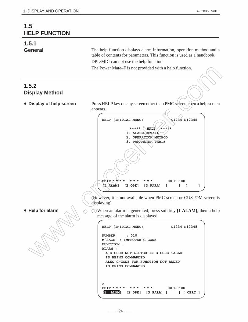
1.5 HELP FUNCTION
1.6 DISPLAYING DIAGNOSTIC PAGE
1.7 POWER MATE STATE DISPLAY
1.8 OPERATION HISTORY
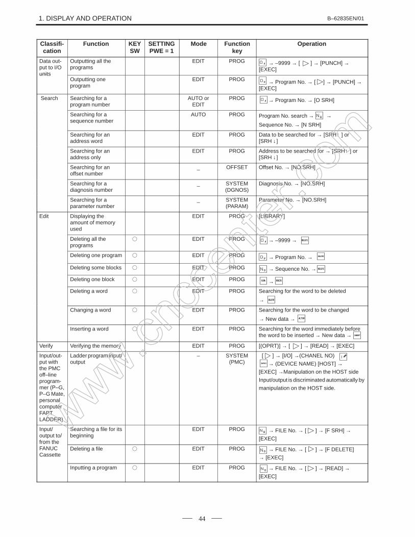
1.9 LIST OF OPERATIONS (CRT/MDI)
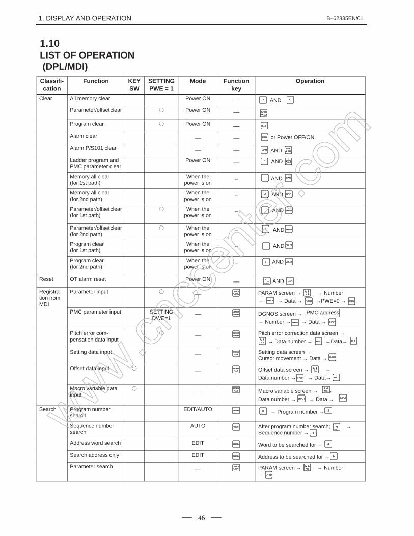
1.10 LIST OF OPERATIONS (DPL/MDI)
1.11 WARNING SCREEN DISPLAYED WHEN AN
OPTION IS CHANGED
www.cncc
enter
.com
1. DISPLAY AND OPERATION B–62835EN/01
2
Operations and soft key display staturs for each function key are describedbelow.
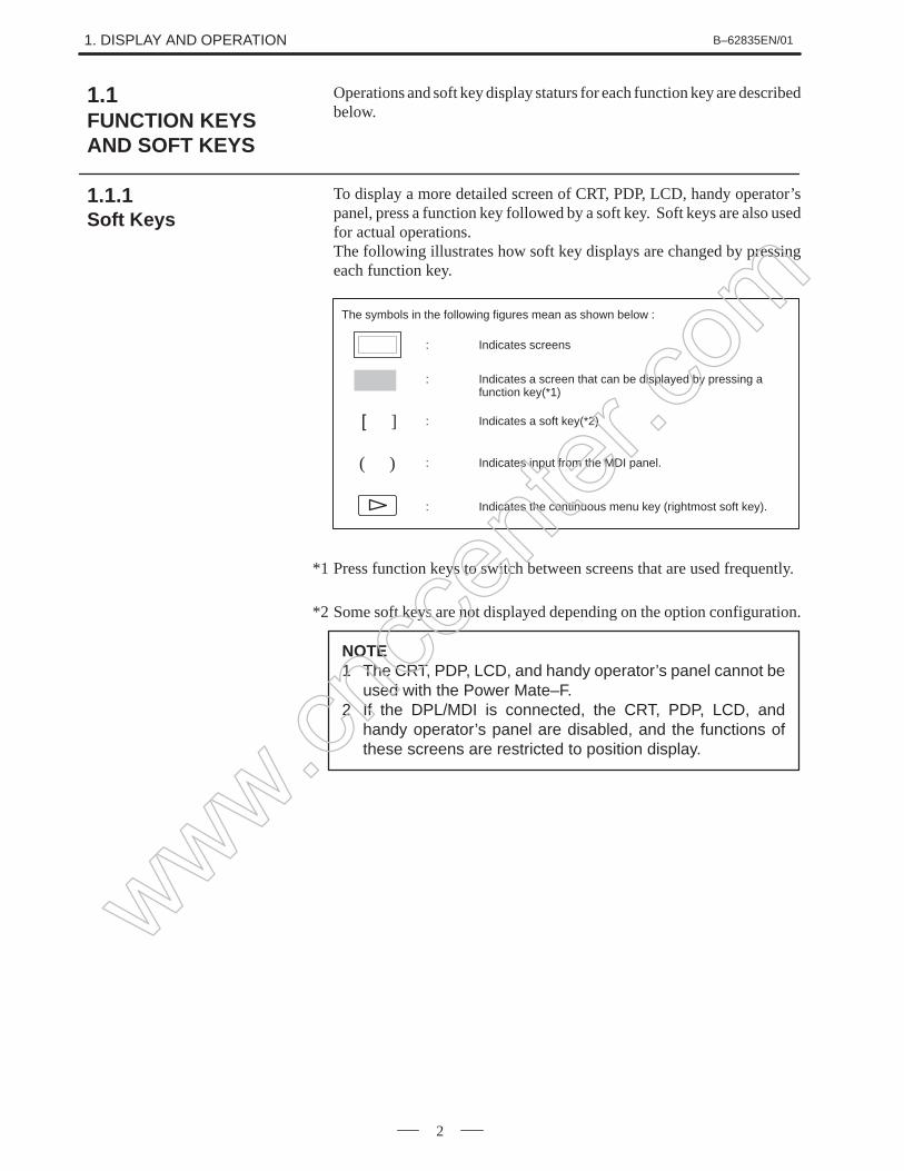
To display a more detailed screen of CRT, PDP, LCD, handy operator’spanel, press a function key followed by a soft key. Soft keys are also usedfor actual operations.The following illustrates how soft key displays are changed by pressingeach function key.
: Indicates a screen that can be displayed by pressing afunction key(*1)
: Indicates a soft key(*2)
: Indicates input from the MDI panel.
: Indicates the continuous menu key (rightmost soft key).
]
( )
The symbols in the following figures mean as shown below :
: Indicates screens
*1 Press function keys to switch between screens that are used frequently.
*2 Some soft keys are not displayed depending on the option configuration.
NOTE1 The CRT, PDP, LCD, and handy operator’s panel cannot be
used with the Power Mate–F.2 If the DPL/MDI is connected, the CRT, PDP, LCD, and
handy operator’s panel are disabled, and the functions ofthese screens are restricted to position display.
1.1FUNCTION KEYSAND SOFT KEYS
1.1.1Soft Keys
www.cncc
enter
.com
B–62835EN/01 1. DISPLAY AND OPERATION
3
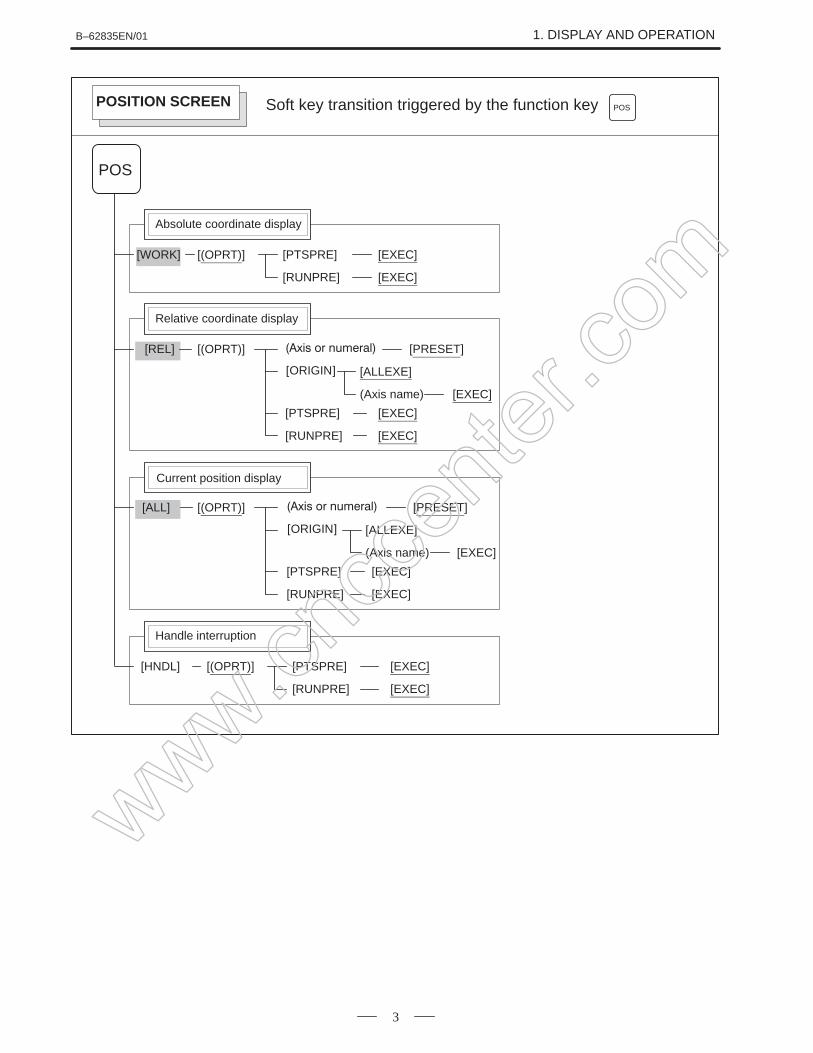
[(OPRT)] [PTSPRE] [EXEC]
[RUNPRE] [EXEC]
[WORK]
Absolute coordinate display
POS
[(OPRT)][REL]
ORIGIN
[PRESET]
[ALLEXE]
(Axis name) [EXEC]
[PTSPRE] [EXEC]
[RUNPRE] [EXEC]
[ALL]
Soft key transition triggered by the function key POSPOSITION SCREEN
Relative coordinate display
Current position display
[(OPRT)]
ORIGIN
[PRESET]
[ALLEXE]
(Axis name) [EXEC]
[PTSPRE] [EXEC]
[RUNPRE] [EXEC]
[(OPRT)] [PTSPRE] [EXEC]
[RUNPRE] [EXEC]
[HNDL]
Handle interruption
www.cncc
enter
.com
1. DISPLAY AND OPERATION B–62835EN/01
4
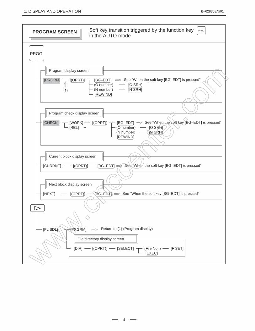
[WORK]
[(OPRT)] [BG–EDT][O SRH]
[PRGRM]
Program display screen
PROG
Soft key transition triggered by the function keyin the AUTO mode
PROG
[N SRH][REWIND]
See “When the soft key [BG–EDT] is pressed”
[(OPRT)][CHECK]
Program check display screen
[REL]
Current block display screen
[(OPRT)] [BG–EDT][CURRNT]
Next block display screen
[(OPRT)] [BG–EDT][NEXT]
(O number)(N number)
PROGRAM SCREEN
See “When the soft key [BG–EDT] is pressed”
See “When the soft key [BG–EDT] is pressed”
[BG–EDT][O SRH][N SRH]
[REWIND]
See “When the soft key [BG–EDT] is pressed”(O number)(N number)
[FL.SDL] [PRGRM]
File directory display screen
[(OPRT)][DIR] [SELECT][EXEC]
(File No. ) [F SET]
Return to (1) (Program display)
www.cncc
enter
.com
B–62835EN/01 1. DISPLAY AND OPERATION
5
1/2
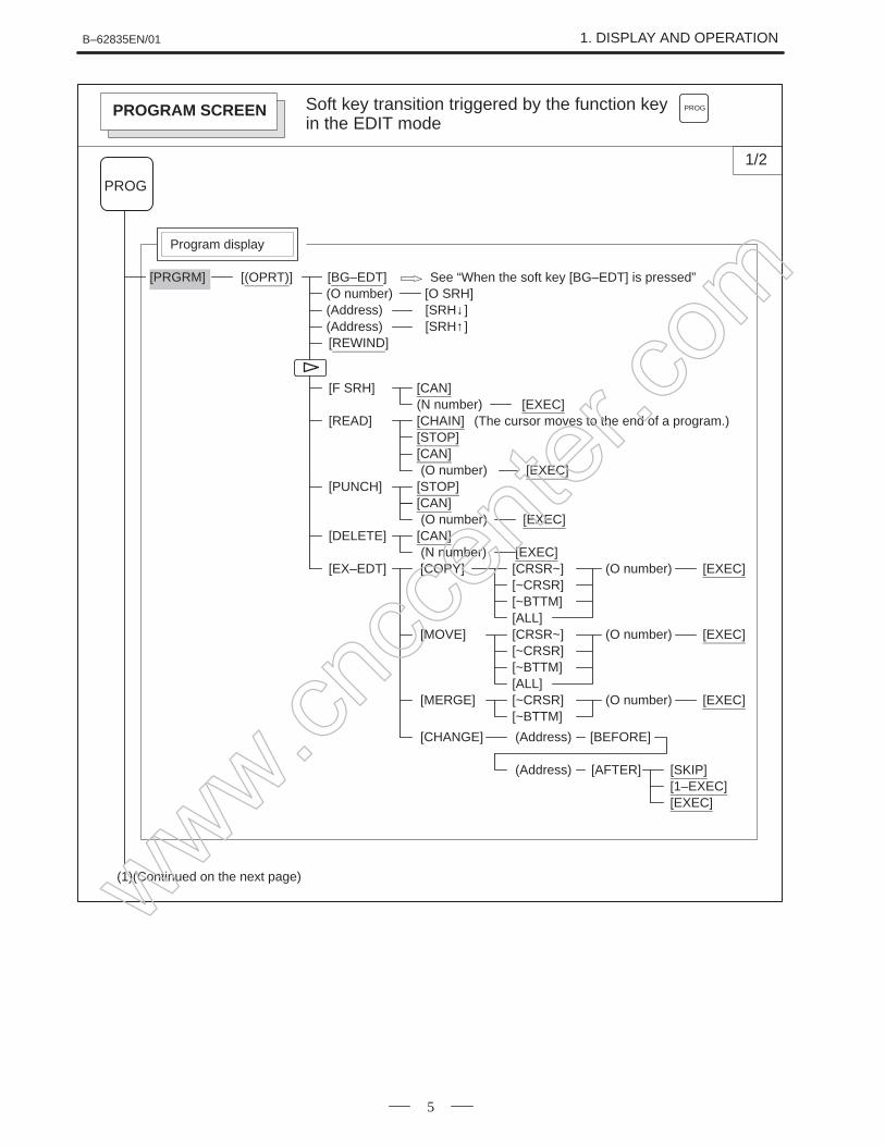
[(OPRT)] [BG–EDT](O number) [O SRH]
[PRGRM]
Program display
PROG
(Address) [SRH↓ ]
[REWIND](Address) [SRH↑ ]
[F SRH] [CAN](N number) [EXEC]
[READ] [CHAIN][STOP][CAN]
[EXEC][PUNCH] [STOP]
[CAN][EXEC]
[DELETE] [CAN][EXEC]
[EX–EDT] [COPY] [CRSR~][~CRSR][~BTTM][ALL]
[MOVE] [CRSR~][~CRSR][~BTTM][ALL]
[MERGE] [~CRSR][~BTTM]
[CHANGE] (Address) [BEFORE]
(Address) [AFTER] [SKIP][1–EXEC][EXEC]
(1)(Continued on the next page)
(The cursor moves to the end of a program.)
(O number)
(O number)
(N number)
Soft key transition triggered by the function keyin the EDIT mode
PROGPROGRAM SCREEN
(O number) [EXEC]
(O number) [EXEC]
(O number) [EXEC]
See “When the soft key [BG–EDT] is pressed”
www.cncc
enter
.com
1. DISPLAY AND OPERATION B–62835EN/01
6
(1)2/2
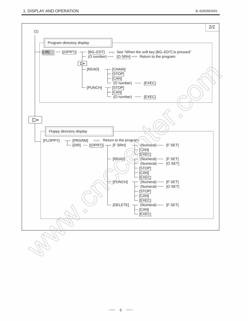
[(OPRT)] [BG–EDT](O number) [O SRH]
[LIB]
Program directory display
[READ] [CHAIN][STOP][CAN]
[EXEC][PUNCH] [STOP]
[CAN][EXEC]
(O number)
(O number)
Return to the programSee “When the soft key [BG–EDT] is pressed”
[F SRH][CAN][EXEC]
[READ]
[STOP][CAN]
[PUNCH]
[F SET]
[F SET]
[EXEC]
[O SET]
[STOP][CAN]
[F SET]
[EXEC]
[O SET]
[DELETE][CAN]
[F SET]
[EXEC]
Floppy directory display
[FLOPPY][DIR] (Numeral)
(Numeral)(Numeral)
(Numeral)(Numeral)
(Numeral)
[PRGRM][(OPRT)]
Return to the program
www.cncc
enter
.com
B–62835EN/01 1. DISPLAY AND OPERATION
7
[(OPRT)] [BG–EDT][PRGRM]
Program display
PROG
Soft key transition triggered by the function keyin the MDI mode
PROGPROGRAM SCREEN
[(OPRT)] [BG–EDT][MDI]
Program input screen
[START]
(Address)(Address)
[SRH↓ ][SRH↑ ]
[CAN][EXEC]
Current block display screen
[(OPRT)] [BG–EDT][CURRNT]
Next block display screen
[(OPRT)] [BG–EDT][NEXT]
See “When the soft key [BG–EDT] is pressed”
See “When the soft key [BG–EDT] is pressed”
See “When the soft key [BG–EDT] is pressed”
See “When the soft key [BG–EDT] is pressed”
[REWIND]
www.cncc
enter
.com
1. DISPLAY AND OPERATION B–62835EN/01
8
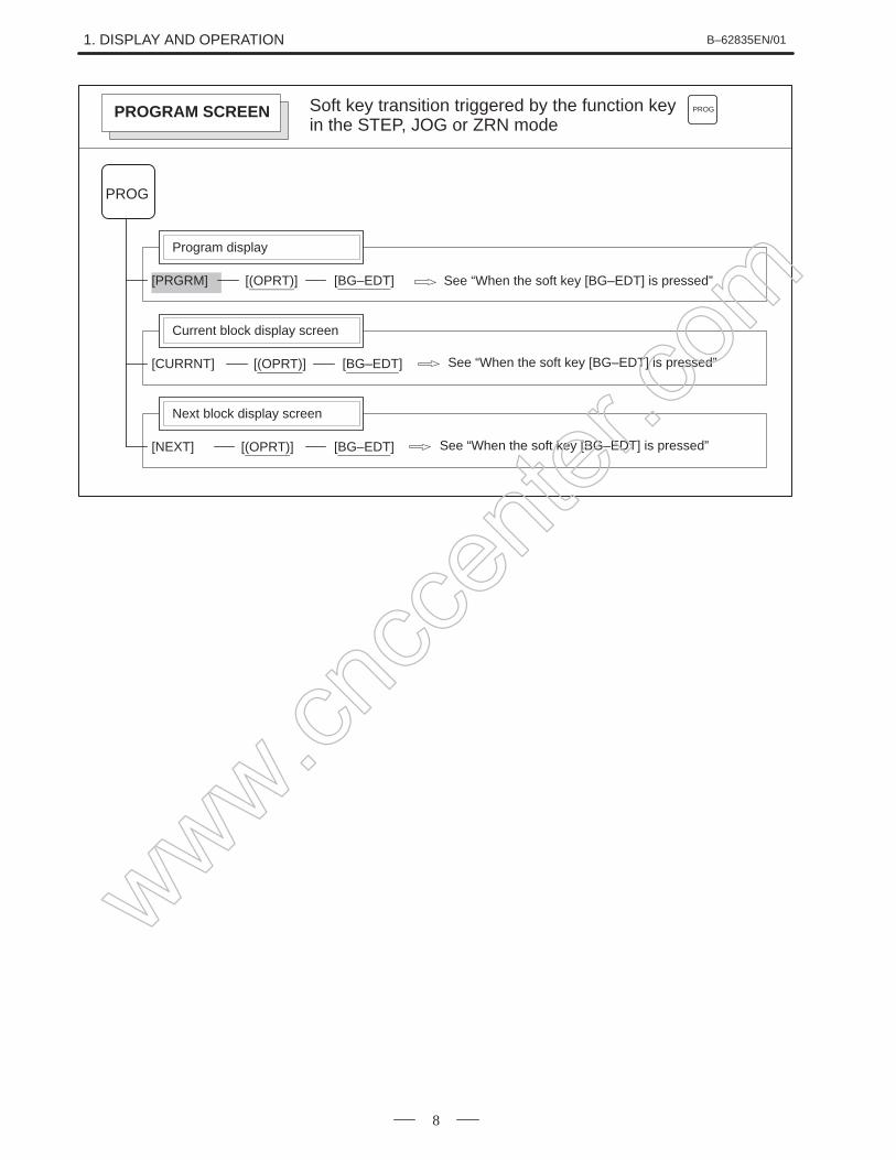
[(OPRT)] [BG–EDT][PRGRM]
Program display
PROG
Soft key transition triggered by the function keyin the STEP, JOG or ZRN mode
PROGPROGRAM SCREEN
Current block display screen
[(OPRT)] [BG–EDT][CURRNT]
Next block display screen
[(OPRT)] [BG–EDT][NEXT]
See “When the soft key [BG–EDT] is pressed”
See “When the soft key [BG–EDT] is pressed”
See “When the soft key [BG–EDT] is pressed”
www.cncc
enter
.com
B–62835EN/01 1. DISPLAY AND OPERATION
9
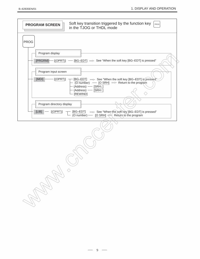
[(OPRT)] [BG–EDT][PRGRM]
Program display
PROG
Soft key transition triggered by the function keyin the TJOG or THDL mode
PROGPROGRAM SCREEN
[(OPRT)] [BG–EDT][MDI]
Program input screen
(Address)(Address)
[SRH↓ ][SRH↑ ]
(O number)
[REWIND]
[(OPRT)] [BG–EDT](O number) [O SRH]
[LIB]
Program directory display
Return to the program
See “When the soft key [BG–EDT] is pressed”
See “When the soft key [BG–EDT] is pressed”
See “When the soft key [BG–EDT] is pressed”
[O SRH] Return to the program
www.cncc
enter
.com
1. DISPLAY AND OPERATION B–62835EN/01
10
1/2
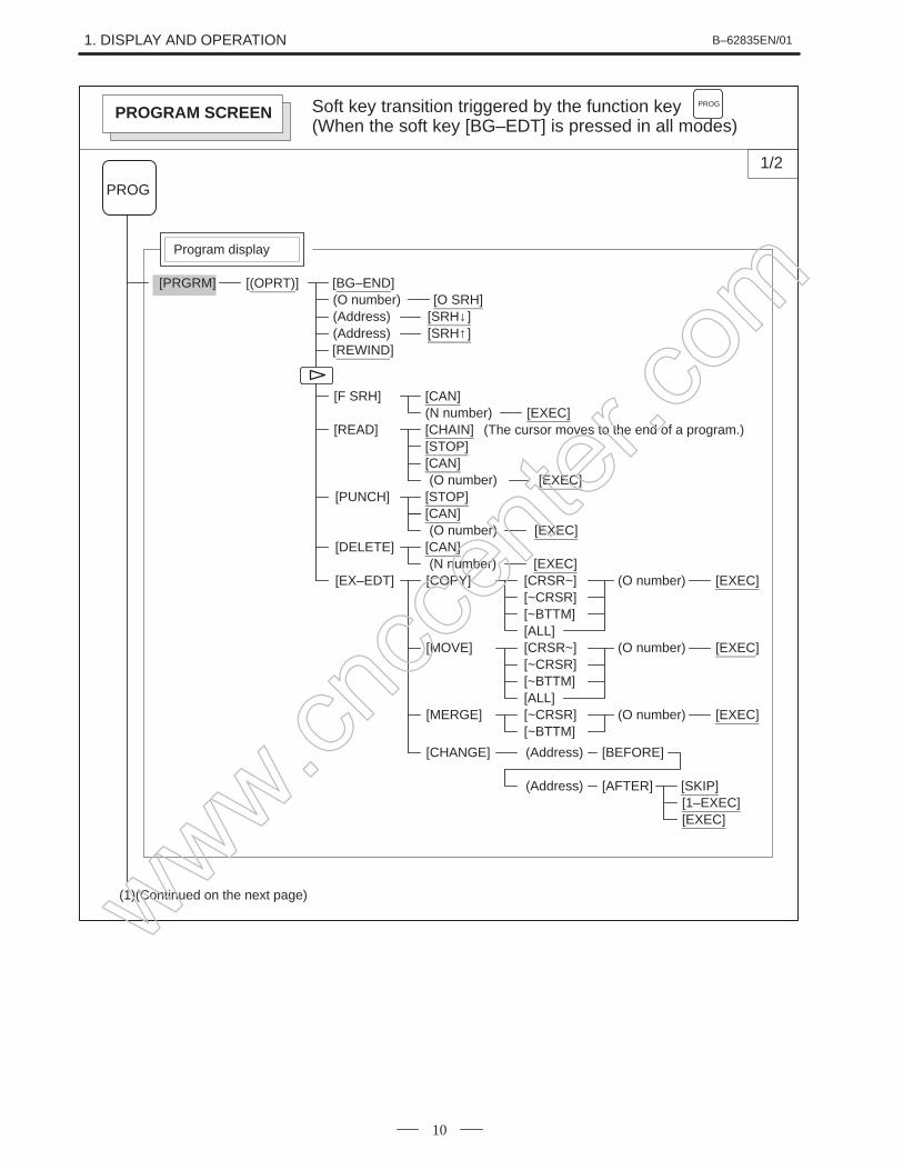
[(OPRT)] [BG–END](O number) [O SRH]
[PRGRM]
Program display
PROG
(Address) [SRH↓ ]
[REWIND](Address) [SRH↑ ]
[F SRH] [CAN](N number) [EXEC]
[READ] [CHAIN][STOP][CAN]
[EXEC][PUNCH] [STOP]
[CAN][EXEC]
[DELETE] [CAN][EXEC]
[EX–EDT] [COPY] [CRSR~][~CRSR][~BTTM][ALL]
[MOVE] [CRSR~][~CRSR][~BTTM][ALL]
[MERGE] [~CRSR][~BTTM]
[CHANGE] (Address) [BEFORE]
(Address) [AFTER] [SKIP][1–EXEC][EXEC]
(1)(Continued on the next page)
(The cursor moves to the end of a program.)
(O number)
(O number)
(N number)
Soft key transition triggered by the function key(When the soft key [BG–EDT] is pressed in all modes)
PROG
PROGRAM SCREEN
(O number) [EXEC]
(O number) [EXEC]
(O number) [EXEC]
www.cncc
enter
.com
B–62835EN/01 1. DISPLAY AND OPERATION
11
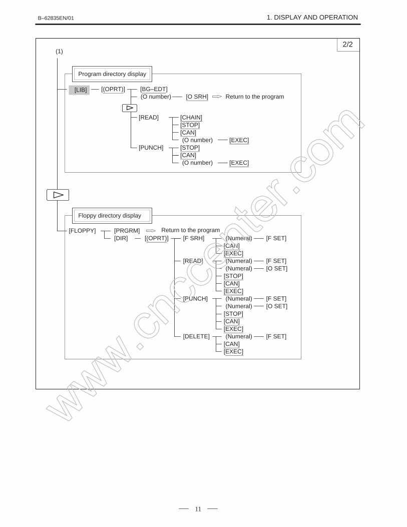
[(OPRT)] [BG–EDT](O number) [O SRH]
[LIB]
Program directory display
[READ] [CHAIN][STOP][CAN]
[EXEC][PUNCH] [STOP]
[CAN][EXEC]
(1)
(O number)
(O number)
[F SRH][CAN][EXEC]
[READ]
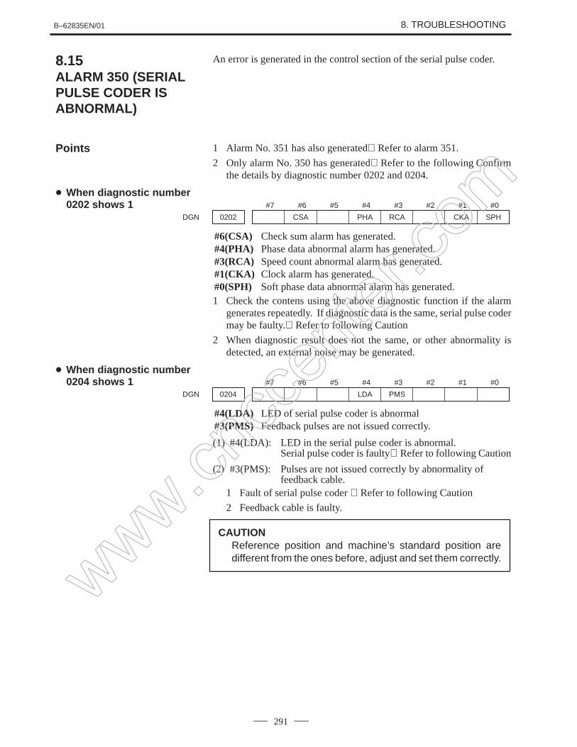
[STOP][CAN]
[PUNCH]
[F SET]
[F SET]
[EXEC]
[O SET]
[STOP][CAN]
[F SET]
[EXEC]
[O SET]
[DELETE][CAN]
[F SET]
[EXEC]
Floppy directory display
[FLOPPY][DIR]
2/2
Return to the program
(Numeral)
(Numeral)(Numeral)
(Numeral)(Numeral)
(Numeral)
[PRGRM][(OPRT)]
Return to the program
www.cncc
enter
.com
1. DISPLAY AND OPERATION B–62835EN/01
12
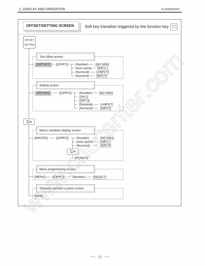
[(OPRT)][OFFSET]
Tool offset screen
Soft key transition triggered by the function key
OFFSET
SETTING
(Number)(Axis name)(Numeral)(Numeral)
[NO SRH][INP.C.]
[+INPUT][INPUT]
[(OPRT)][SETING]
Setting screen
(Numeral)(Numeral)
[NO SRH]
[+INPUT][INPUT]
[ON:1][OFF:0]
(Number)
[(OPRT)][MACRO]
Macro variables display screen
(Numeral)
[NO SRH]
[INPUT]
(Number)(Axis name) [INP.C.]
[PUNCH]
OFFSET
SETTINGOFFSET/SETTING SCREEN
[OPR]
Software operator’s panel screen
[MENU]
Menu programming screen
[(OPRT)] (Number) [SELECT]
www.cncc
enter
.com
B–62835EN/01 1. DISPLAY AND OPERATION
13
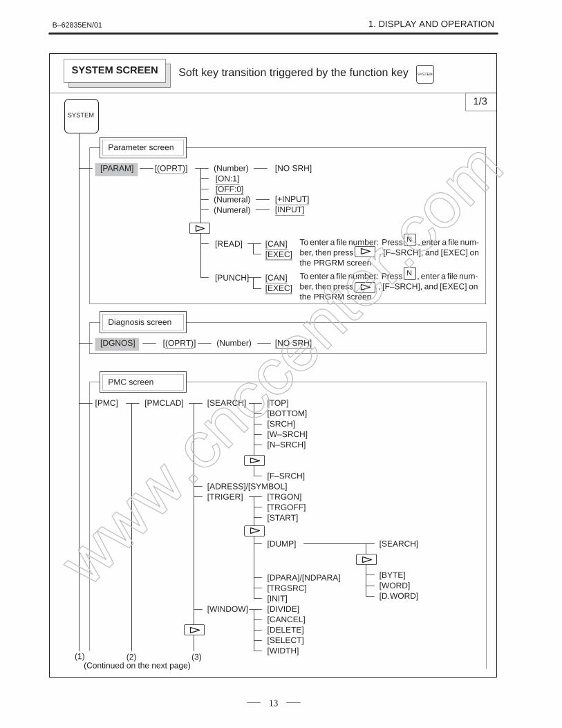
Soft key transition triggered by the function key
[(OPRT)][PARAM]
Parameter screen
(Numeral)(Numeral)
[NO SRH]
[+INPUT][INPUT]
[ON:1][OFF:0]
(Number)
SYSTEM
SYSTEM
[READ] [CAN][EXEC]
[PUNCH] [CAN][EXEC]
[(OPRT)][DGNOS]
Diagnosis screen
[NO SRH](Number)
[PMCLAD][PMC]
PMC screen
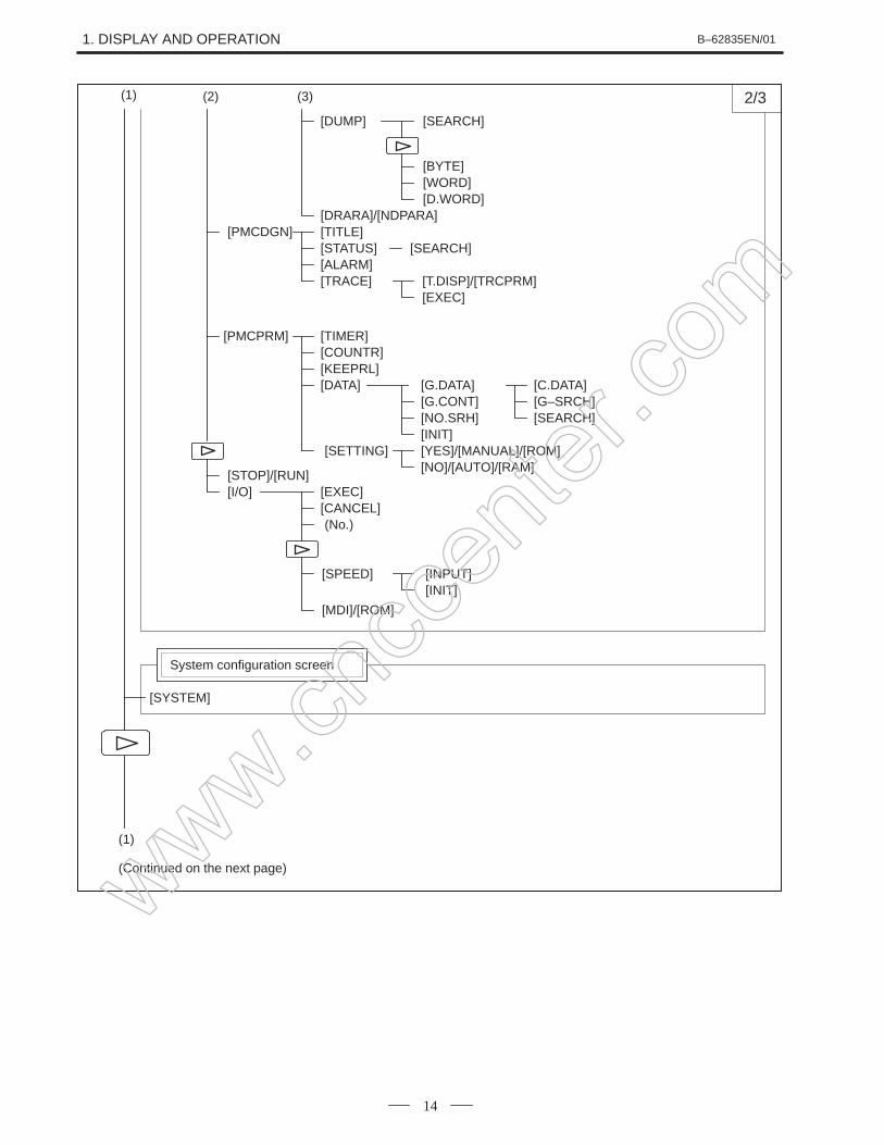
(1) (Continued on the next page)
(2)
1/3
SYSTEM SCREEN
To enter a file number: Press , enter a file num-ber, then press , [F–SRCH], and [EXEC] onthe PRGRM screen
N
To enter a file number: Press , enter a file num-ber, then press , [F–SRCH], and [EXEC] onthe PRGRM screen
To enter a file number: Press , enter a file num-ber, then press , [F–SRCH], and [EXEC] onthe PRGRM screen
N
To enter a file number: Press , enter a file num-ber, then press , [F–SRCH], and [EXEC] onthe PRGRM screen
N
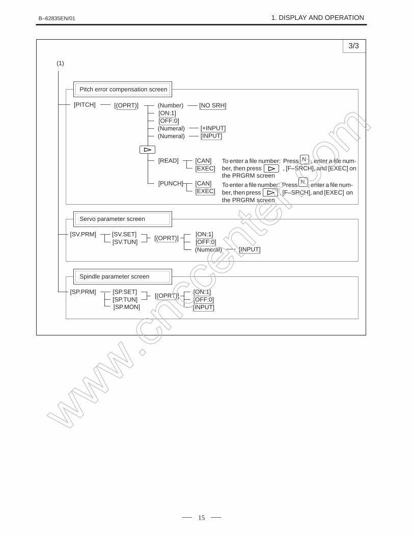
[(OPRT)][SP.PRM]
Spindle parameter screen
[ON:1][OFF:0]
[SP.SET][SP.TUN]
[INPUT][SP.MON]
(1)
www.cncc
enter
.com
1. DISPLAY AND OPERATION B–62835EN/01
16
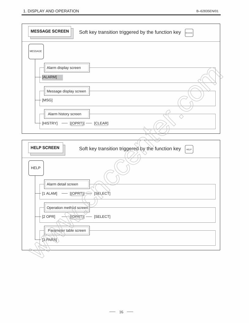
Soft key transition triggered by the function key
[ALARM]
Alarm display screen
MESSAGE
MESSAGE
[MSG]
Message display screen
[HISTRY]
Alarm history screen
[(OPRT)] [CLEAR]
[1 ALAM]
Soft key transition triggered by the function key
Alarm detail screen
HELP
HELP
[2 OPR]
Operation method screen
[3 PARA]
Parameter table screen
[(OPRT)] [SELECT]
[(OPRT)] [SELECT]
www.cncc
enter
.com
B–62835EN/01 1. DISPLAY AND OPERATION
17
/AND
9
Q
Function key
Program edit key
Input key
Cursor move key
Date input key
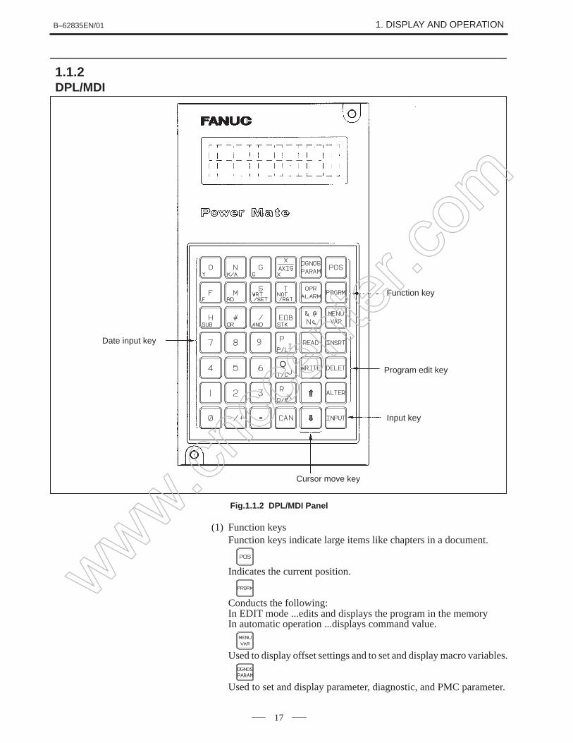
Fig.1.1.2 DPL/MDI Panel
(1) Function keysFunction keys indicate large items like chapters in a document.
Indicates the current position.
Conducts the following:In EDIT mode ...edits and displays the program in the memoryIn automatic operation ...displays command value.
Used to display offset settings and to set and display macro variables.
Used to set and display parameter, diagnostic, and PMC parameter.
1.1.2DPL/MDI
www.cncc
enter
.com
1. DISPLAY AND OPERATION B–62835EN/01
18
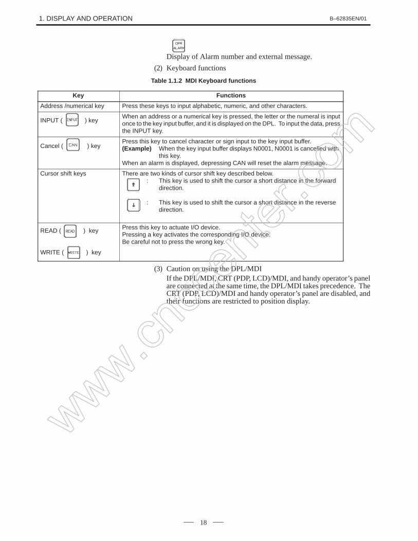
Display of Alarm number and external message.
(2) Keyboard functions
Table 1.1.2 MDI Keyboard functions
Key Functions
Address /numerical key Press these keys to input alphabetic, numeric, and other characters.
INPUT ( ) keyWhen an address or a numerical key is pressed, the letter or the numeral is inputonce to the key input buffer, and it is displayed on the DPL. To input the data, pressthe INPUT key.
Cancel ( ) keyPress this key to cancel character or sign input to the key input buffer.(Example) When the key input buffer displays N0001, N0001 is cancelled with
this key.When an alarm is displayed, depressing CAN will reset the alarm message.
Cursor shift keys There are two kinds of cursor shift key described below.: This key is used to shift the cursor a short distance in the forward
direction.
: This key is used to shift the cursor a short distance in the reverse direction.
READ ( ) key
WRITE ( ) key
Press this key to actuate I/O device.Pressing a key activates the corresponding I/O device. Be careful not to press the wrong key.
(3) Caution on using the DPL/MDIIf the DPL/MDI, CRT (PDP, LCD)/MDI, and handy operator’s panelare connected at the same time, the DPL/MDI takes precedence. TheCRT (PDP, LCD)/MDI and handy operator’s panel are disabled, andtheir functions are restricted to position display.
www.cncc
enter
.com
B–62835EN/01 1. DISPLAY AND OPERATION
19
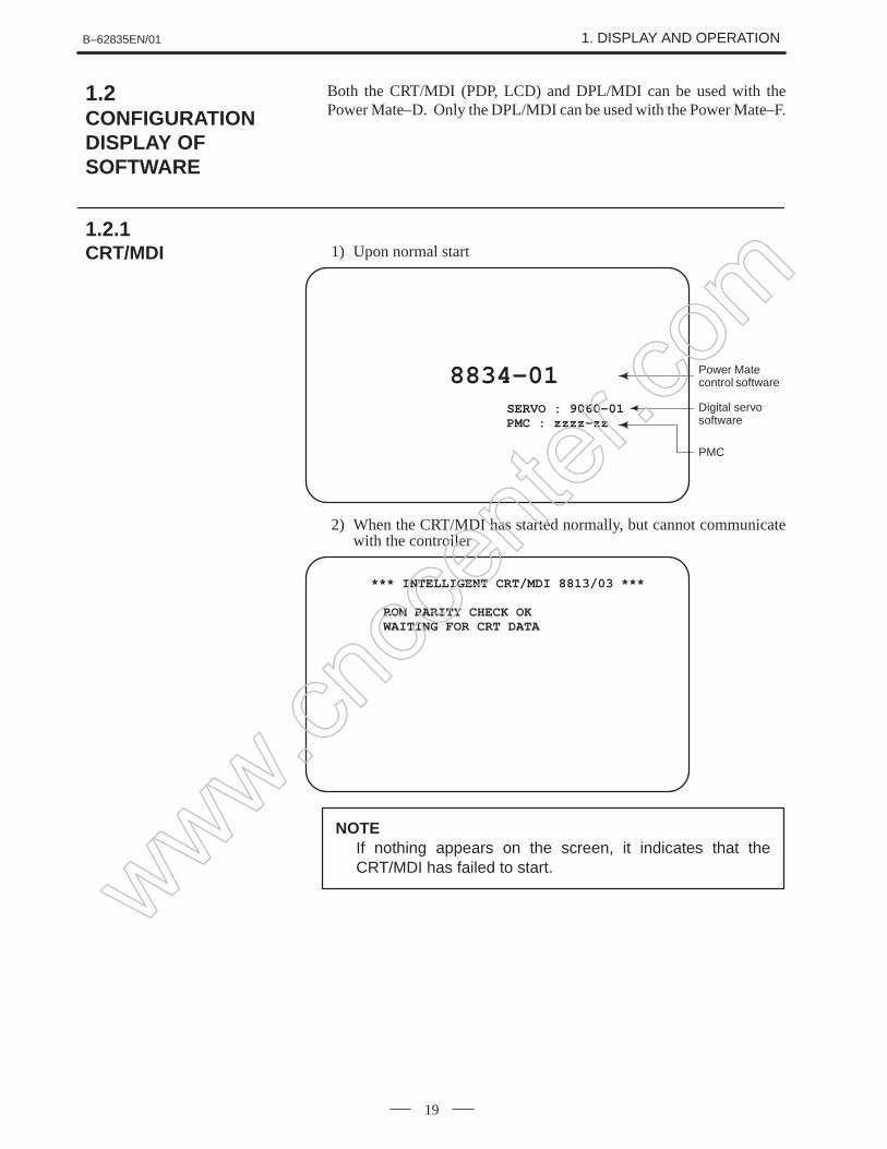
Both the CRT/MDI (PDP, LCD) and DPL/MDI can be used with thePower Mate–D. Only the DPL/MDI can be used with the Power Mate–F.
1) Upon normal start
8834–01SERVO : 9060–01PMC : zzzz–zz
PMC
Power Matecontrol software
Digital servosoftware
2) When the CRT/MDI has started normally, but cannot communicatewith the controller
*** INTELLIGENT CRT/MDI 8813/03 ***
ROM PARITY CHECK OKWAITING FOR CRT DATA
NOTEIf nothing appears on the screen, it indicates that theCRT/MDI has failed to start.
1.2CONFIGURATIONDISPLAY OFSOFTWARE
1.2.1CRT/MDI
www.cncc
enter
.com
1. DISPLAY AND OPERATION B–62835EN/01
20
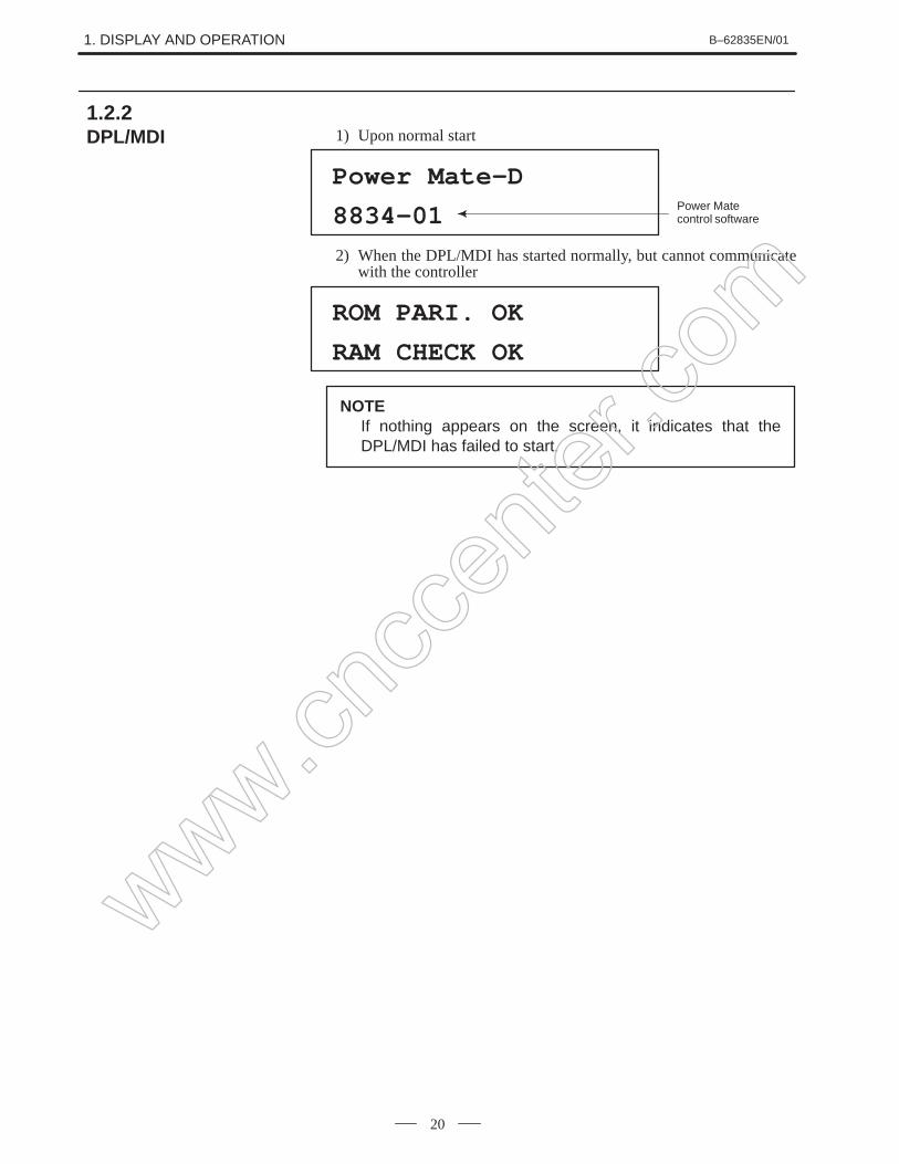
1) Upon normal start
Power Mate–D
8834–01 Power Matecontrol software
2) When the DPL/MDI has started normally, but cannot communicatewith the controller
ROM PARI. OK
RAM CHECK OK
NOTEIf nothing appears on the screen, it indicates that theDPL/MDI has failed to start.
1.2.2DPL/MDI
www.cncc
enter
.com
B–62835EN/01 1. DISPLAY AND OPERATION
21
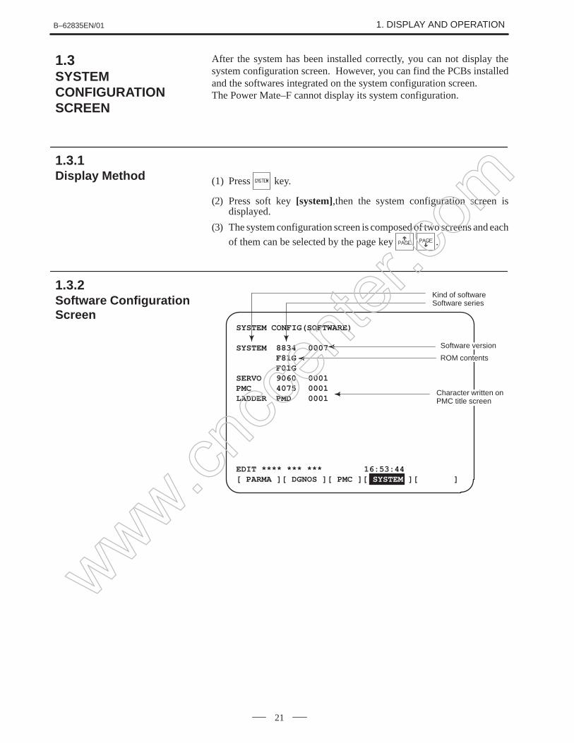
After the system has been installed correctly, you can not display thesystem configuration screen. However, you can find the PCBs installedand the softwares integrated on the system configuration screen.The Power Mate–F cannot display its system configuration.
(1) Press key.
(2) Press soft key [system],then the system configuration screen isdisplayed.
(3) The system configuration screen is composed of two screens and each
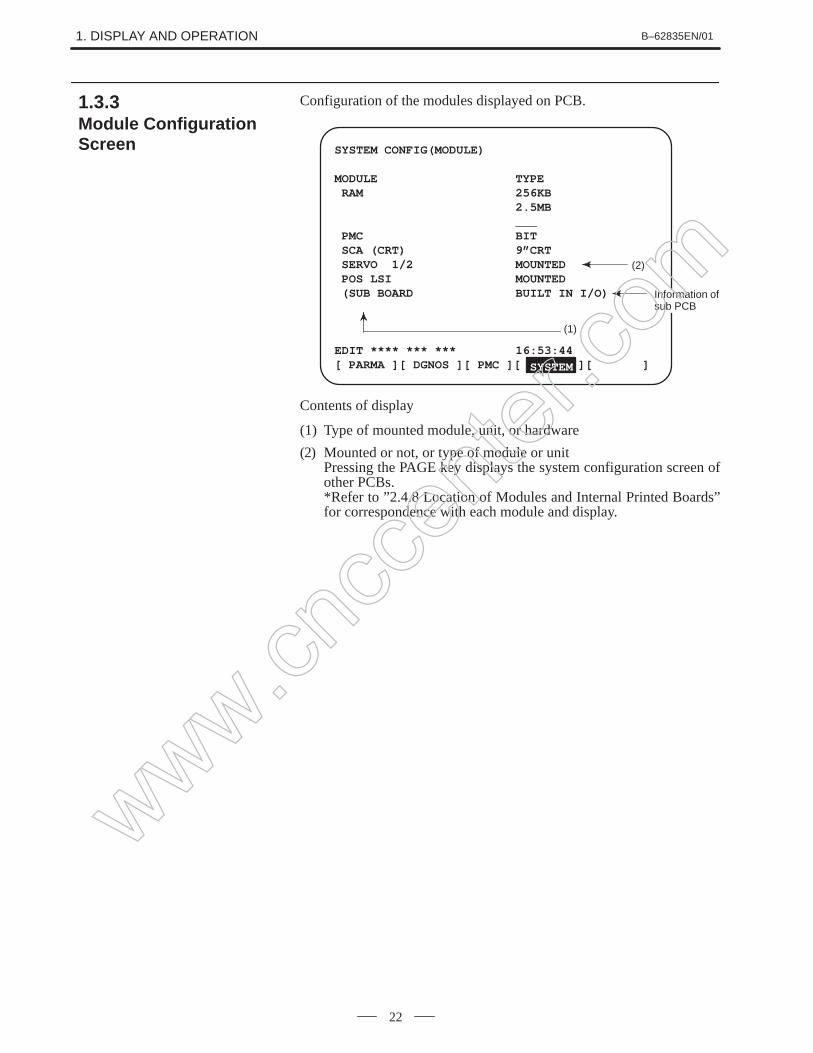
(2) Mounted or not, or type of module or unitPressing the PAGE key displays the system configuration screen ofother PCBs.*Refer to ”2.4.8 Location of Modules and Internal Printed Boards”for correspondence with each module and display.
1.3.3Module ConfigurationScreen
www.cncc
enter
.com
B–62835EN/01 1. DISPLAY AND OPERATION
23
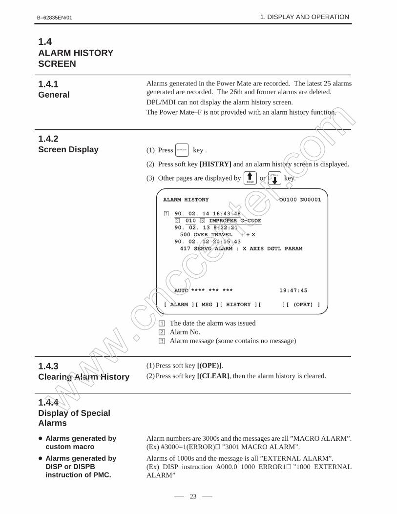
Alarms generated in the Power Mate are recorded. The latest 25 alarmsgenerated are recorded. The 26th and former alarms are deleted.
DPL/MDI can not display the alarm history screen.
The Power Mate–F is not provided with an alarm history function.
(1) Press MESSAGE key .
(2) Press soft key [HISTRY] and an alarm history screen is displayed.
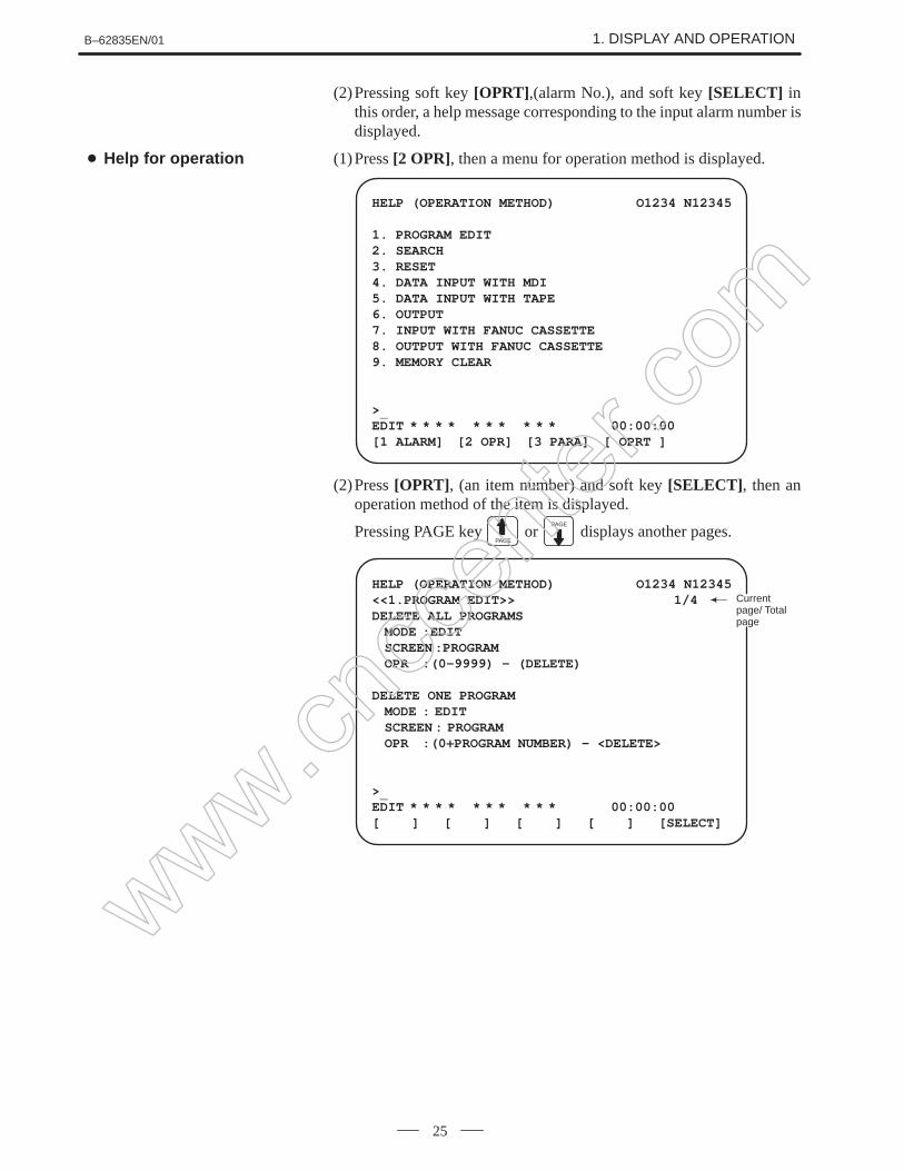
(2)Pressing soft key [OPRT] ,(alarm No.), and soft key [SELECT] inthis order, a help message corresponding to the input alarm number isdisplayed.
(1)Press [2 OPR], then a menu for operation method is displayed.
HELP (OPERATION METHOD) O1234 N12345
1. PROGRAM EDIT2. SEARCH3. RESET4. DATA INPUT WITH MDI5. DATA INPUT WITH TAPE6. OUTPUT7. INPUT WITH FANUC CASSETTE8. OUTPUT WITH FANUC CASSETTE9. MEMORY CLEAR
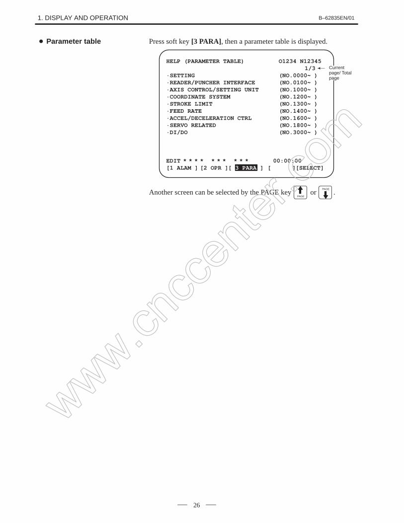
Another screen can be selected by the PAGE key PAGE
or PAGE
.
Parameter table
www.cncc
enter
.com
B–62835EN/01 1. DISPLAY AND OPERATION
27
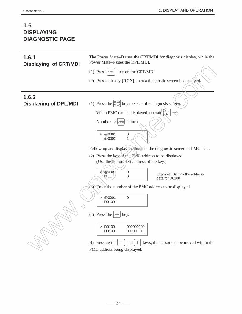
The Power Mate–D uses the CRT/MDI for diagnosis display, while thePower Mate–F uses the DPL/MDI.
(1) Press SYSTEM key on the CRT/MDI.
(2) Press soft key [DGN] , then a diagnostic screen is displayed.
(1) Press the key to select the diagnosis screen.
When PMC data is displayed, operate
Number in turn.
> @0001 0@0002 1
Following are display methods in the diagnostic screen of PMC data.
(2) Press the key of the PMC address to be displayed.(Use the bottom left address of the key.)
> @0001 0D_ 0
Example: Display the addressdata for D0100
(3) Enter the number of the PMC address to be displayed.
> @0001 0D0100
(4) Press the key.
> D0100 000000000D0100 000001010
By pressing the and keys, the cursor can be moved within the
PMC address being displayed.
1.6DISPLAYINGDIAGNOSTIC PAGE
1.6.1Displaying of CRT/MDI
1.6.2Displaying of DPL/MDI
www.cncc
enter
.com
1. DISPLAY AND OPERATION B–62835EN/01
28
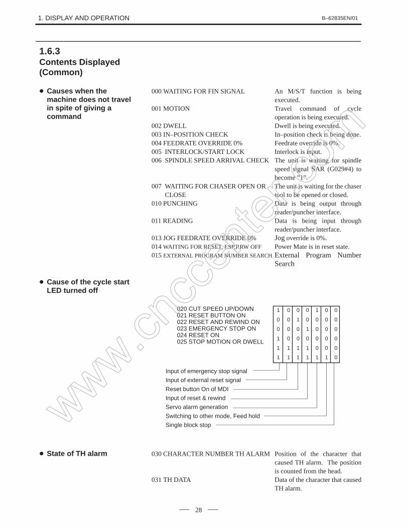
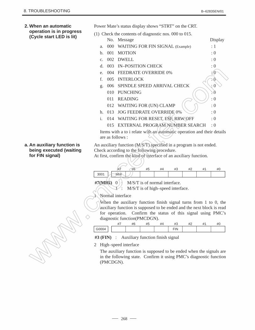
000 WAITING FOR FIN SIGNAL An M/S/T function is beingexecuted.
001 MOTION Travel command of cycleoperation is being executed.
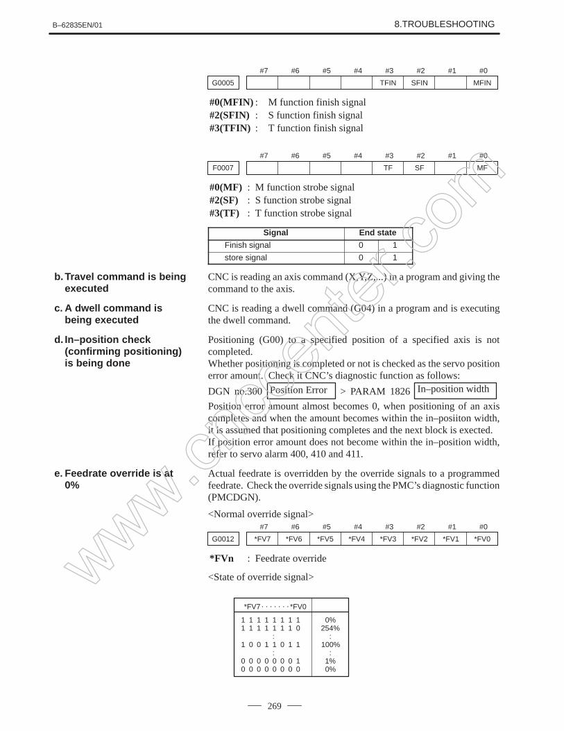
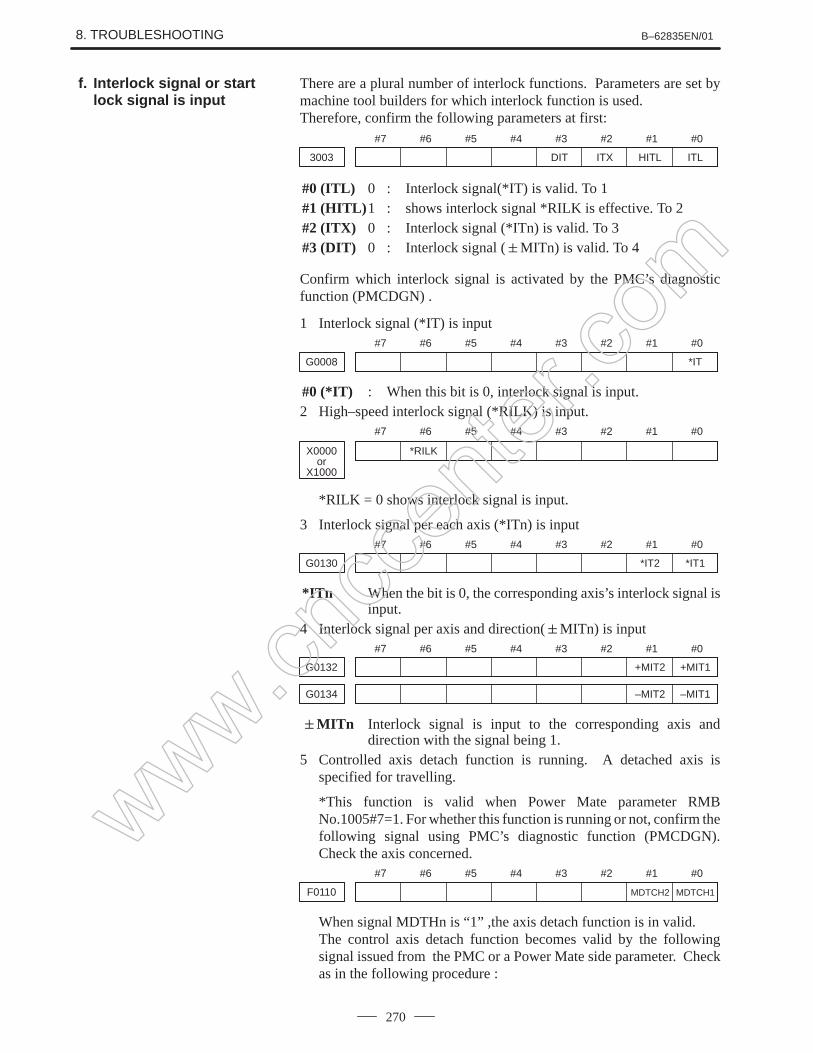
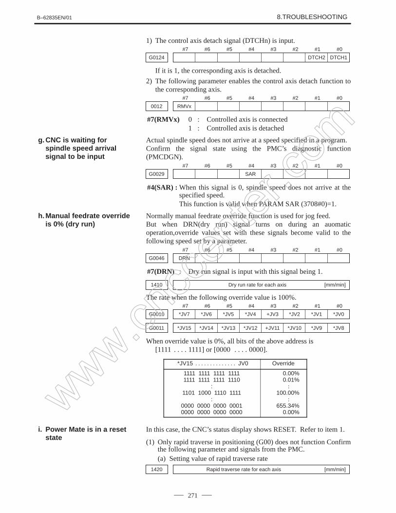
002 DWELL Dwell is being executed.003 IN–POSITION CHECK In–position check is being done.004 FEEDRATE OVERRIDE 0% Feedrate override is 0%.005 INTERLOCK/START LOCK Interlock is input.006 SPINDLE SPEED ARRIVAL CHECK The unit is waiting for spindle
speed signal SAR (G029#4) tobecome ”1”.
007 WAITING FOR CHASER OPEN OR The unit is waiting for the chaserCLOSE tool to be opened or closed.
010 PUNCHING Data is being output throughreader/puncher interface.
011 READING Data is being input throughreader/puncher interface.
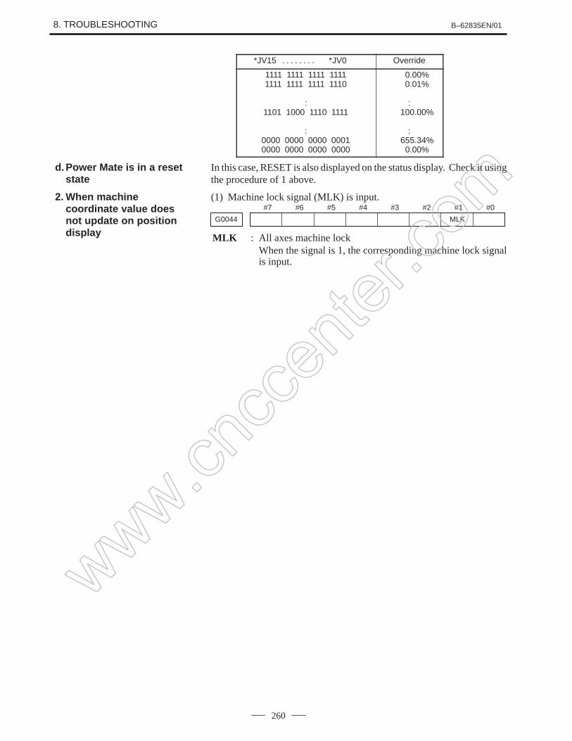
013 JOG FEEDRATE OVERRIDE 0% Jog override is 0%.014 WAITING FOR RESET, ESP,RRW OFF Power Mate is in reset state.015 EXTERNAL PROGRAM NUMBER SEARCHExternal Program Number
Search
1 0 0 0 1 0 0
0 0 1 0 0 0 0
0 0 0 1 0 0 0
1 0 0 0 0 0 0
1 1 1 1 0 0 0
1 1 1 1 1 1 0
020 CUT SPEED UP/DOWN021 RESET BUTTON ON022 RESET AND REWIND ON023 EMERGENCY STOP ON024 RESET ON025 STOP MOTION OR DWELL
Input of emergency stop signal
Input of external reset signal
Reset button On of MDI
Input of reset & rewind
Servo alarm generation
Switching to other mode, Feed hold
Single block stop
030 CHARACTER NUMBER TH ALARM Position of the character thatcaused TH alarm. The positionis counted from the head.
031 TH DATA Data of the character that causedTH alarm.
1.6.3Contents Displayed(Common)
Causes when themachine does not travelin spite of giving acommand
Cause of the cycle startLED turned off
State of TH alarm
www.cncc
enter
.com
B–62835EN/01 1. DISPLAY AND OPERATION
29
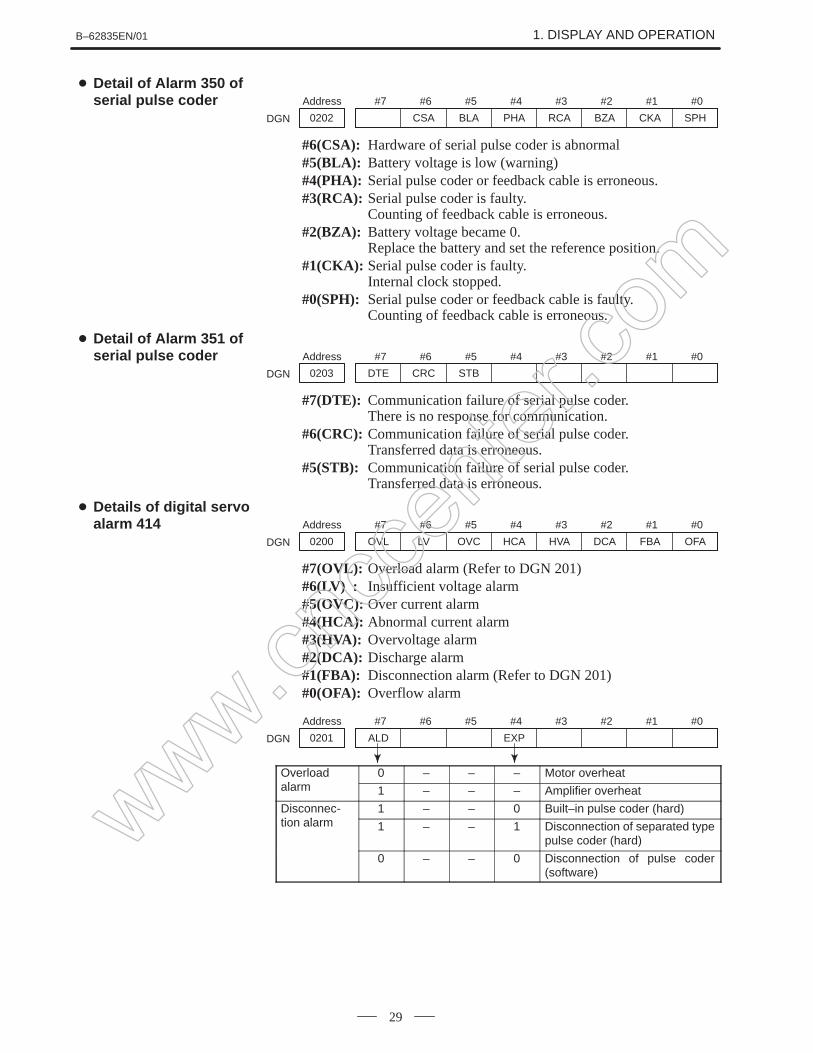
#7 #6 #5 #4 #3 #2 #1 #0Address
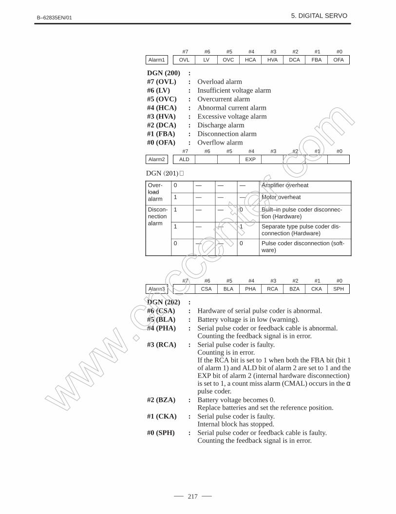
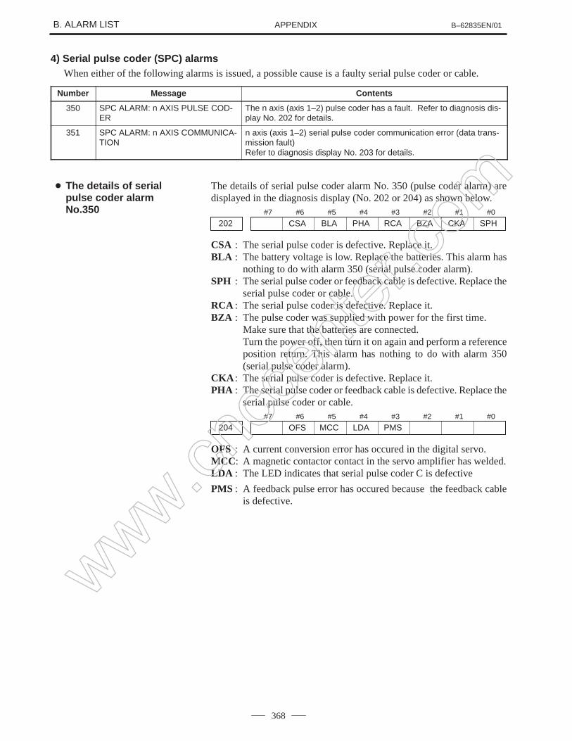
0202 CSA BLA PHA RCA BZA CKA SPHDGN
#6(CSA): Hardware of serial pulse coder is abnormal#5(BLA): Battery voltage is low (warning)#4(PHA): Serial pulse coder or feedback cable is erroneous.#3(RCA): Serial pulse coder is faulty.
Counting of feedback cable is erroneous.#2(BZA): Battery voltage became 0.
Replace the battery and set the reference position.#1(CKA): Serial pulse coder is faulty.
Internal clock stopped.#0(SPH): Serial pulse coder or feedback cable is faulty.
Counting of feedback cable is erroneous.
#7 #6 #5 #4 #3 #2 #1 #0Address
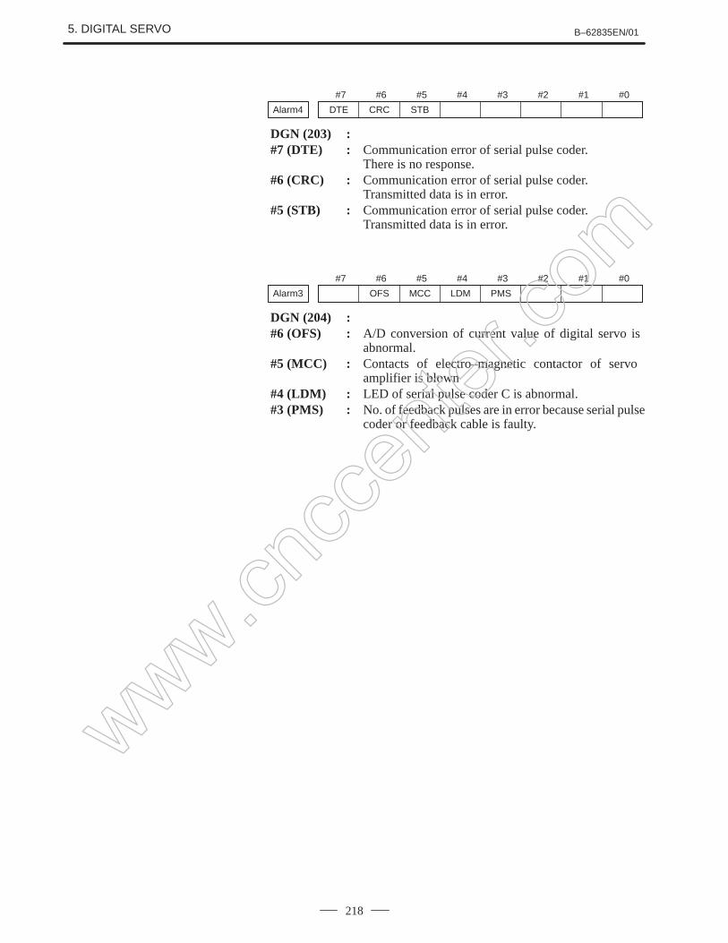
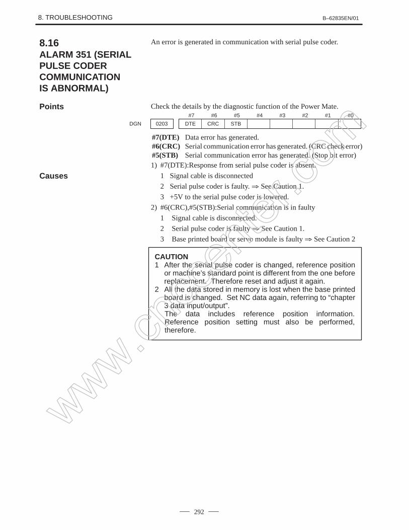
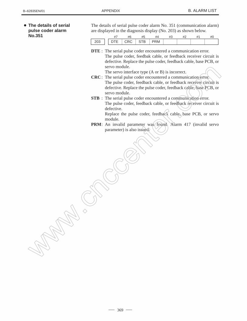
0203 DTE CRC STBDGN
#7(DTE): Communication failure of serial pulse coder.There is no response for communication.
#6(CRC): Communication failure of serial pulse coder.Transferred data is erroneous.
#5(STB): Communication failure of serial pulse coder.Transferred data is erroneous.
#7 #6 #5 #4 #3 #2 #1 #0Address
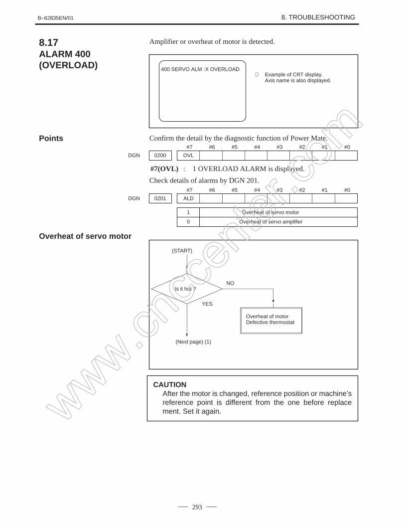
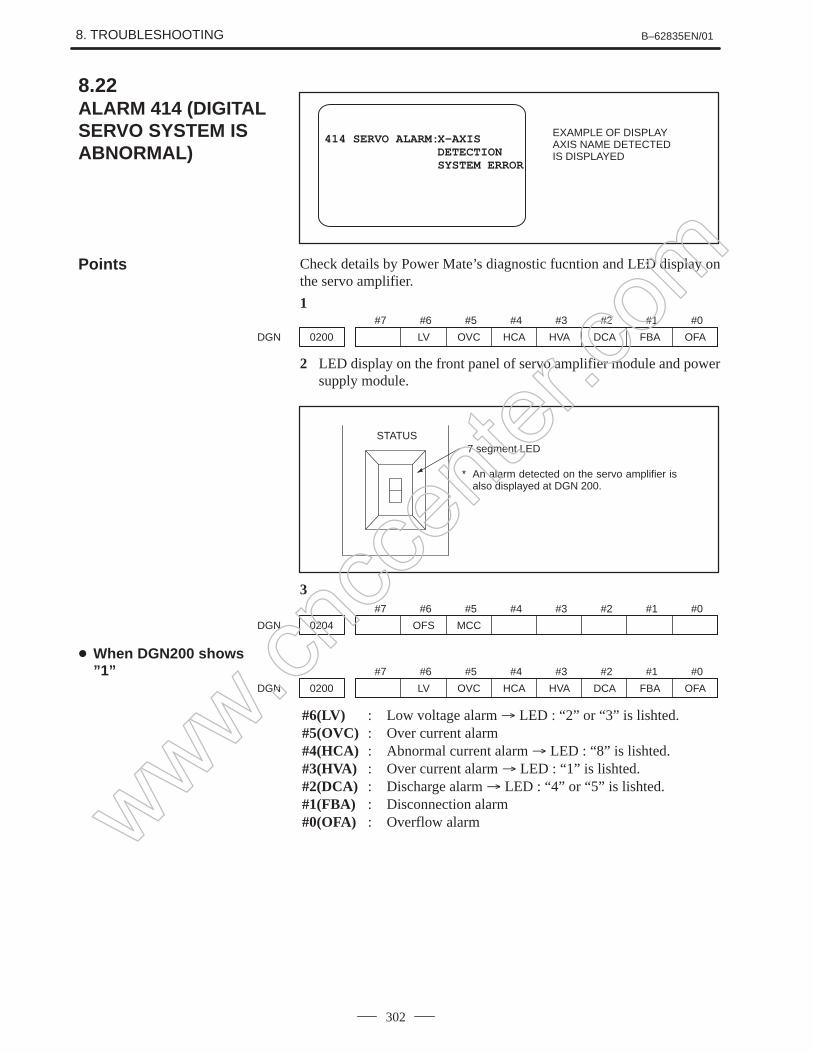
0200 OVL LV OVC HCA HVA DCA FBA OFADGN
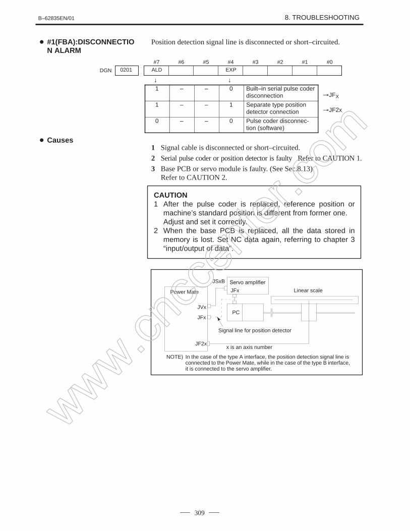
#7(OVL): Overload alarm (Refer to DGN 201)#6(LV) : Insufficient voltage alarm#5(OVC): Over current alarm#4(HCA): Abnormal current alarm#3(HVA): Overvoltage alarm#2(DCA): Discharge alarm#1(FBA): Disconnection alarm (Refer to DGN 201)#0(OFA): Overflow alarm
1 – – 0 Built–in pulse coder (hard)tion alarm 1 – – 1 Disconnection of separated type
pulse coder (hard)
0 – – 0 Disconnection of pulse coder(software)
Detail of Alarm 350 ofserial pulse coder
Detail of Alarm 351 ofserial pulse coder
Details of digital servoalarm 414
www.cncc
enter
.com
1. DISPLAY AND OPERATION B–62835EN/01
30
#7 #6 #5 #4 #3 #2 #1 #0Address
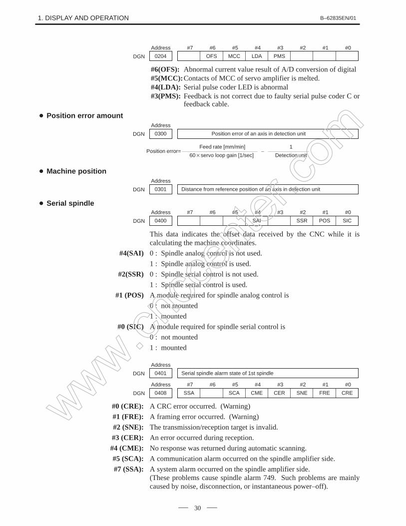
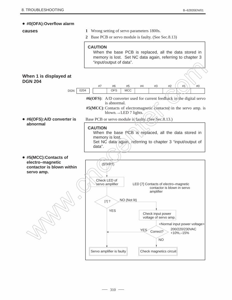
0204 OFS MCC LDA PMSDGN
#6(OFS): Abnormal current value result of A/D conversion of digital#5(MCC): Contacts of MCC of servo amplifier is melted.#4(LDA): Serial pulse coder LED is abnormal#3(PMS): Feedback is not correct due to faulty serial pulse coder C or
feedback cable.
Address
0300 Position error of an axis in detection unitDGN
Position error=Feed rate [mm/min]
60servo loop gain [1/sec]
1
Detection unit_
Address
0301 Distance from reference position of an axis in detection unitDGN
#7 #6 #5 #4 #3 #2 #1 #0Address
0400 SAI SSR POS SICDGN
This data indicates the offset data received by the CNC while it iscalculating the machine coordinates.
#4(SAI) 0 : Spindle analog control is not used.
1 : Spindle analog control is used.
#2(SSR) 0 : Spindle serial control is not used.
1 : Spindle serial control is used.
#1 (POS) A module required for spindle analog control is
0 : not mounted
1 : mounted
#0 (SIC) A module required for spindle serial control is
0 : not mounted
1 : mounted
Address
0401 Serial spindle alarm state of 1st spindleDGN
#7 #6 #5 #4 #3 #2 #1 #0Address
0408 SSA SCA CME CER SNE FRE CREDGN
#0 (CRE): A CRC error occurred. (Warning)
#1 (FRE): A framing error occurred. (Warning)
#2 (SNE): The transmission/reception target is invalid.
#3 (CER): An error occurred during reception.
#4 (CME): No response was returned during automatic scanning.
#5 (SCA): A communication alarm occurred on the spindle amplifier side.
#7 (SSA): A system alarm occurred on the spindle amplifier side.(These problems cause spindle alarm 749. Such problems are mainlycaused by noise, disconnection, or instantaneous power–off).
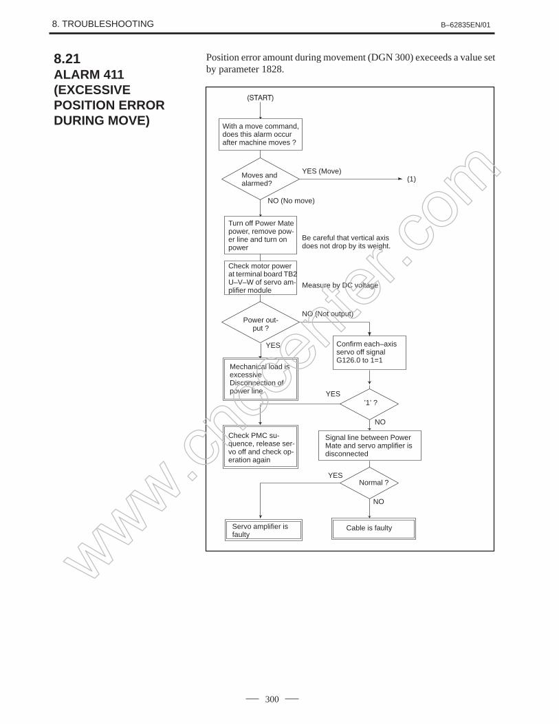
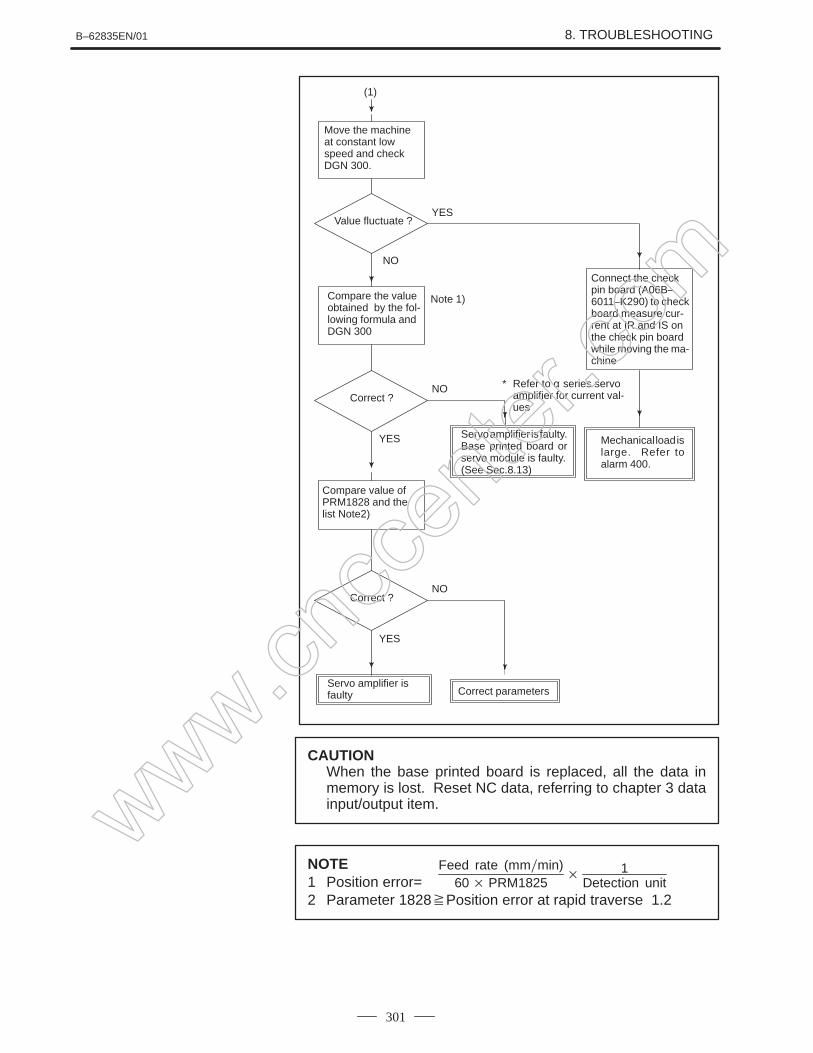
Position error amount
Machine position
Serial spindle
www.cncc
enter
.com
B–62835EN/01 1. DISPLAY AND OPERATION
31
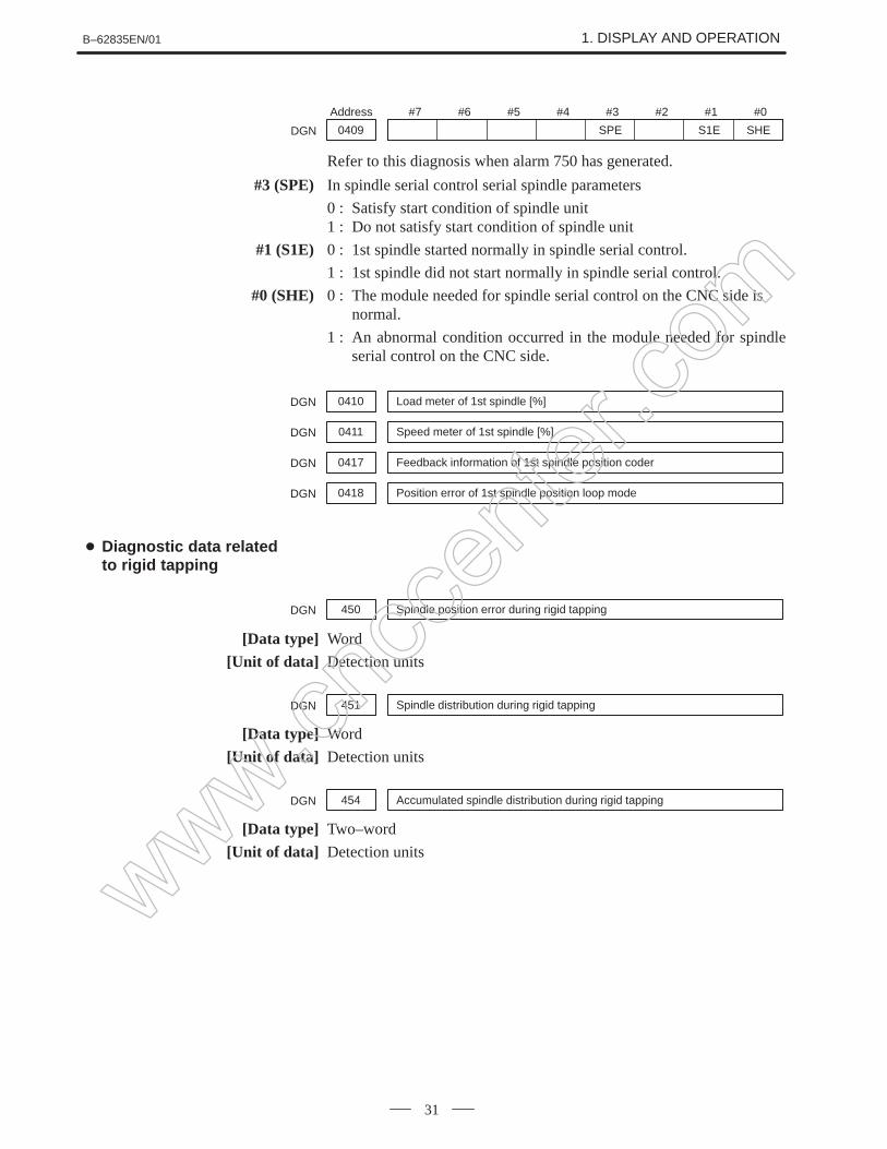
#7 #6 #5 #4 #3 #2 #1 #0Address
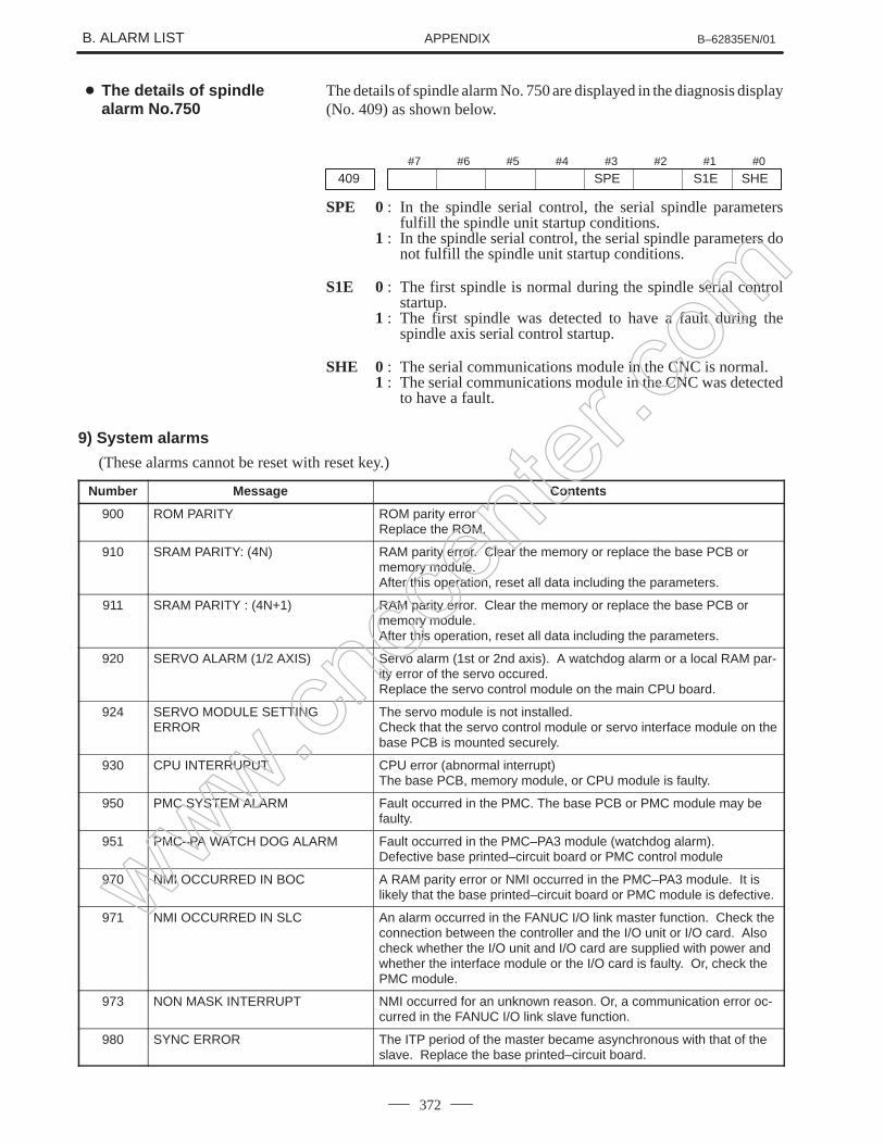
0409 SPE S1E SHEDGN
Refer to this diagnosis when alarm 750 has generated.
#3 (SPE) In spindle serial control serial spindle parameters
0 : Satisfy start condition of spindle unit1 : Do not satisfy start condition of spindle unit
#1 (S1E) 0 : 1st spindle started normally in spindle serial control.
1 : 1st spindle did not start normally in spindle serial control.
#0 (SHE) 0 : The module needed for spindle serial control on the CNC side is normal.
1 : An abnormal condition occurred in the module needed for spindleserial control on the CNC side.
0410 Load meter of 1st spindle [%]DGN
0411 Speed meter of 1st spindle [%]DGN
0417 Feedback information of 1st spindle position coderDGN
0418 Position error of 1st spindle position loop modeDGN
450 Spindle position error during rigid tappingDGN
[Data type] Word
[Unit of data] Detection units
451 Spindle distribution during rigid tappingDGN
[Data type] Word
[Unit of data] Detection units
454 Accumulated spindle distribution during rigid tappingDGN
[Data type] Two–word
[Unit of data] Detection units
Diagnostic data relatedto rigid tapping
www.cncc
enter
.com
1. DISPLAY AND OPERATION B–62835EN/01
32
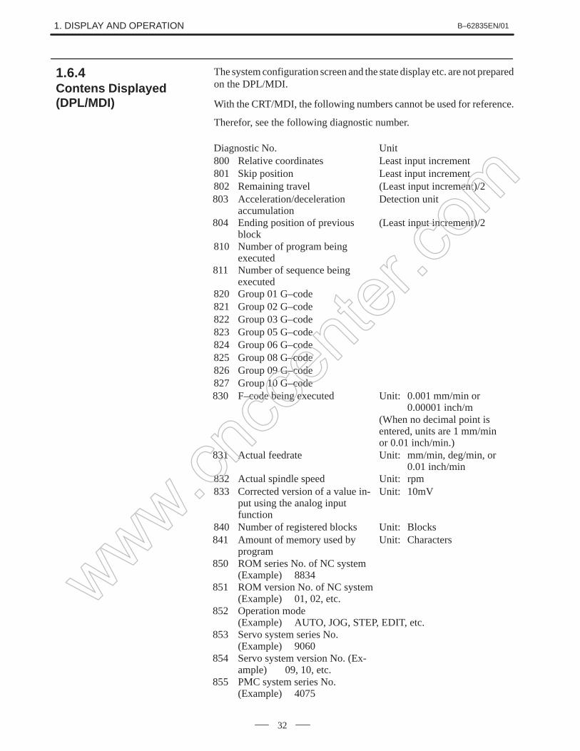
The system configuration screen and the state display etc. are not preparedon the DPL/MDI.
With the CRT/MDI, the following numbers cannot be used for reference.
Therefor, see the following diagnostic number.
Diagnostic No. Unit800 Relative coordinates Least input increment801 Skip position Least input increment802 Remaining travel (Least input increment)/2803 Acceleration/deceleration
accumulationDetection unit
804 Ending position of previousblock
(Least input increment)/2
810 Number of program beingexecuted
811 Number of sequence beingexecuted
820 Group 01 G–code821 Group 02 G–code822 Group 03 G–code823 Group 05 G–code824 Group 06 G–code825 Group 08 G–code826 Group 09 G–code827 Group 10 G–code830 F–code being executed Unit: 0.001 mm/min or
0.00001 inch/m(When no decimal point isentered, units are 1 mm/minor 0.01 inch/min.)
831 Actual feedrate Unit: mm/min, deg/min, or 0.01 inch/min
832 Actual spindle speed Unit: rpm833 Corrected version of a value in-
put using the analog inputfunction
Unit: 10mV
840 Number of registered blocks Unit: Blocks841 Amount of memory used by
programUnit: Characters
850 ROM series No. of NC system(Example) 8834
851 ROM version No. of NC system (Example) 01, 02, etc.
852 Operation mode (Example) AUTO, JOG, STEP, EDIT, etc.
853 Servo system series No. (Example) 9060
854 Servo system version No. (Ex-ample) 09, 10, etc.
855 PMC system series No. (Example) 4075
1.6.4Contens Displayed(DPL/MDI)
www.cncc
enter
.com
B–62835EN/01 1. DISPLAY AND OPERATION
33
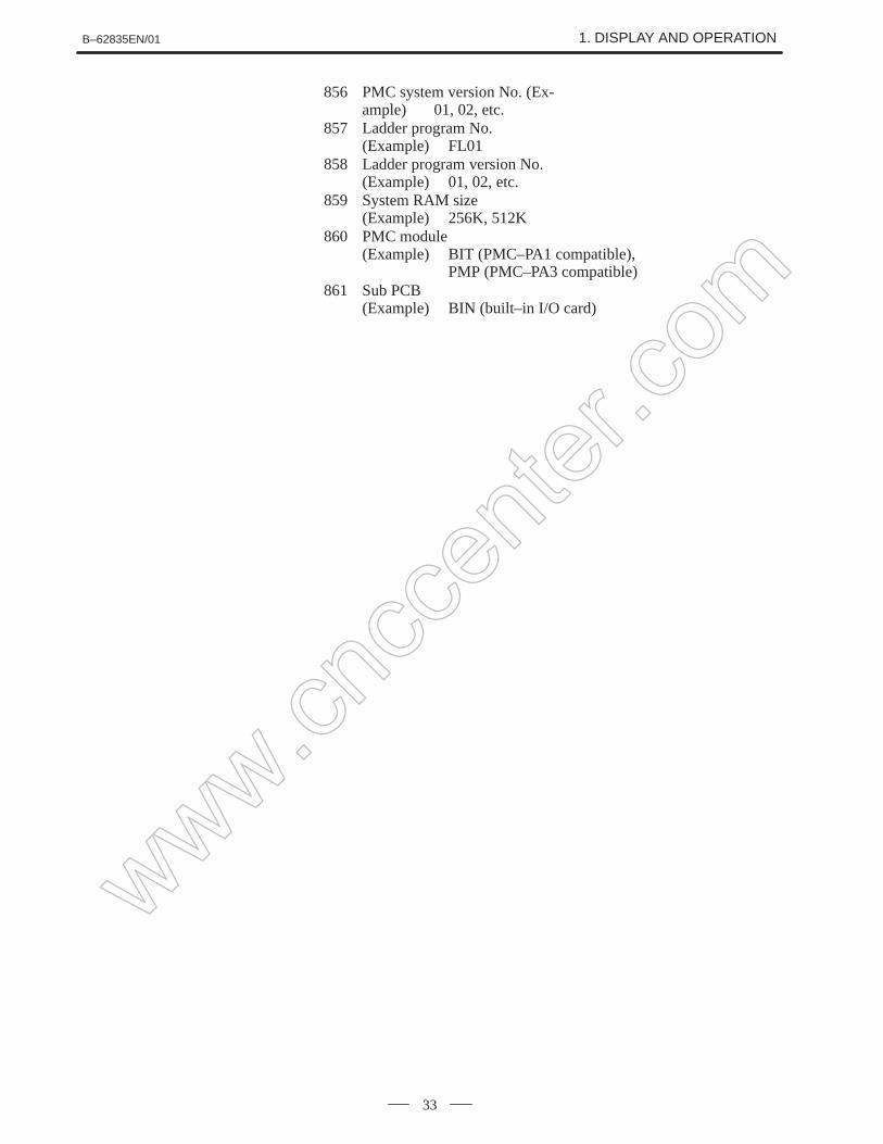
856 PMC system version No. (Ex-ample) 01, 02, etc.
857 Ladder program No. (Example) FL01
858 Ladder program version No.(Example) 01, 02, etc.
859 System RAM size (Example) 256K, 512K
860 PMC module (Example) BIT (PMC–PA1 compatible),
PMP (PMC–PA3 compatible)861 Sub PCB
(Example) BIN (built–in I/O card)
www.cncc
enter
.com
1. DISPLAY AND OPERATION B–62835EN/01
34
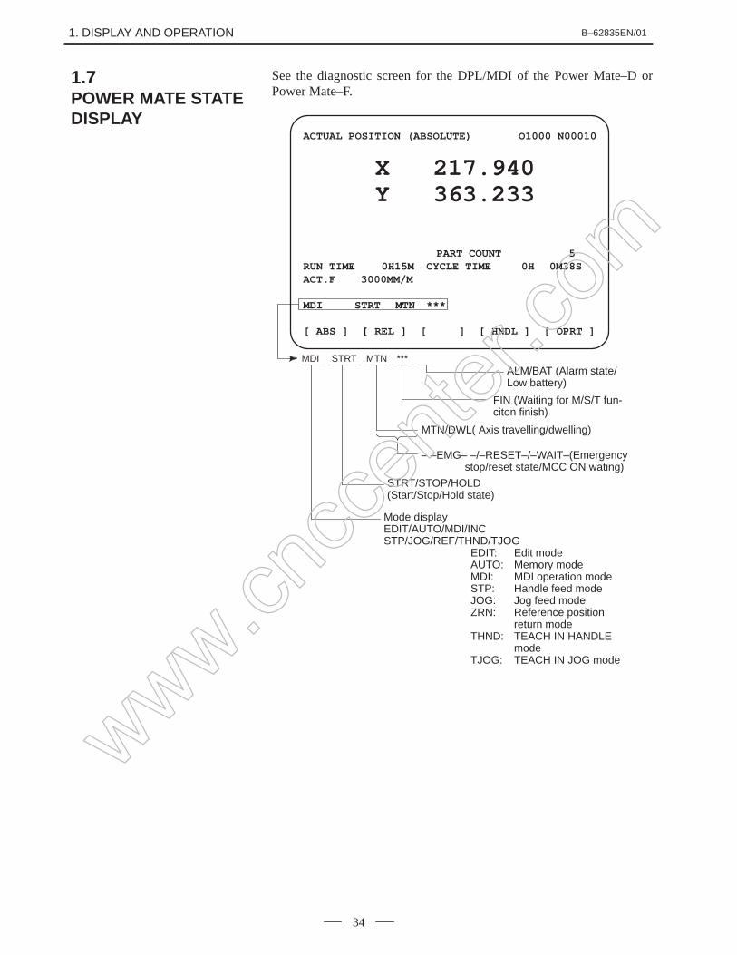
See the diagnostic screen for the DPL/MDI of the Power Mate–D orPower Mate–F.
ACTUAL POSITION (ABSOLUTE) O1000 N00010
X 217.940Y 363.233
PART COUNT 5RUN TIME 0H15M CYCLE TIME 0H 0M38SACT.F 3000MM/M
MDI STRT MTN ***
[ ABS ] [ REL ] [ ALL ] [ HNDL ] [ OPRT ]
MDI STRT MTN ***ALM/BAT (Alarm state/Low battery)
FIN (Waiting for M/S/T fun-citon finish)
MTN/DWL( Axis travelling/dwelling)
– –EMG– –/–RESET–/–WAIT–(Emergency stop/reset state/MCC ON wating)
EDIT: Edit modeAUTO: Memory modeMDI: MDI operation modeSTP: Handle feed modeJOG: Jog feed modeZRN: Reference position
return modeTHND: TEACH IN HANDLE
modeTJOG: TEACH IN JOG mode
STRT/STOP/HOLD(Start/Stop/Hold state)
1.7POWER MATE STATEDISPLAY
www.cncc
enter
.com
B–62835EN/01 1. DISPLAY AND OPERATION
35
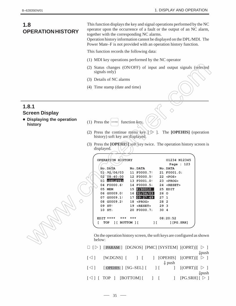
This function displays the key and signal operations performed by the NCoperator upon the occurrence of a fault or the output of an NC alarm,together with the corresponding NC alarms.Operation history information cannot be displayed on the DPL/MDI. ThePower Mate–F is not provided with an operation history function.
This function records the following data:
(1) MDI key operations performed by the NC operator
(2) Status changes (ON/OFF) of input and output signals (selectedsignals only)
(3) Details of NC alarms
(4) Time stamp (date and time)
(1) Press the SYSTEM function key.
(2) Press the continue menu key [ ]. The [OPEHIS] (operationhistory) soft key are displayed.
(3) Press the [OPEHIS] soft key twice. The operation history screen isdisplayed.
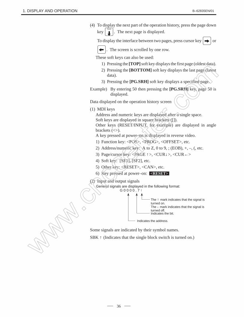
(4) To display the next part of the operation history, press the page down
key PAGE
. The next page is displayed.
To display the interface between two pages, press cursor key or
. The screen is scrolled by one row.
These soft keys can also be used:
1) Pressing the [TOP] soft key displays the first page (oldest data).
2) Pressing the [BOTTOM] soft key displays the last page (latestdata).
3) Pressing the [PG.SRH] soft key displays a specified page.
Example) By entering 50 then pressing the [PG.SRH] key, page 50 isdisplayed.
Data displayed on the operation history screen
(1) MDI keysAddress and numeric keys are displayed after a single space.Soft keys are displayed in square brackets ([]).Other keys (RESET/INPUT, for example) are displayed in anglebrackets (<>).A key pressed at power–on is displayed in reverse video.
1) Function key: <POS>, <PROG>, <OFFSET>, etc.
2) Address/numeric key: A to Z, 0 to 9, ; (EOB), +, –, (, etc.
3) Page/cursor key: <PAGE ↑>, <CUR↓>, <CUR←>
4) Soft key: [SF1], [SF2], etc.
5) Other key: <RESET>, <CAN>, etc.
6) Key pressed at power–on: <RESET>
(2) Input and output signals
Indicates the bit.
General signals are displayed in the following format:G 0 0 0 0 . 7 ↑
The ↑ mark indicates that the signal isturned on.The ↓ mark indicates that the signal isturned off.
Indicates the address.
Some signals are indicated by their symbol names.
SBK ↑ (Indicates that the single block switch is turned on.)www.cncc
enter
.com
B–62835EN/01 1. DISPLAY AND OPERATION
37
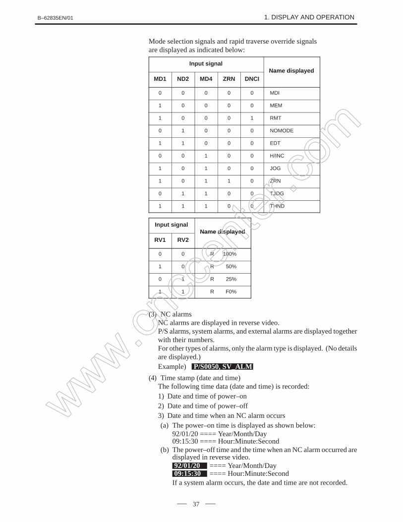
Mode selection signals and rapid traverse override signalsare displayed as indicated below:
Input signalName displayed
MD1 ND2 MD4 ZRN DNCIName displayed
0 0 0 0 0 MDI
1 0 0 0 0 MEM
1 0 0 0 1 RMT
0 1 0 0 0 NOMODE
1 1 0 0 0 EDT
0 0 1 0 0 H/INC
1 0 1 0 0 JOG
1 0 1 1 0 ZRN
0 1 1 0 0 TJOG
1 1 1 0 0 THND
Input signalName displayed
RV1 RV2Name displayed
0 0 R 100%
1 0 R 50%
0 1 R 25%
1 1 R F0%
(3) NC alarmsNC alarms are displayed in reverse video.P/S alarms, system alarms, and external alarms are displayed togetherwith their numbers. For other types of alarms, only the alarm type is displayed. (No detailsare displayed.)Example) P/S0050, SV_ALM
(4) Time stamp (date and time)The following time data (date and time) is recorded:1) Date and time of power–on2) Date and time of power–off3) Date and time when an NC alarm occurs(a) The power–on time is displayed as shown below:
(b) The power–off time and the time when an NC alarm occurred aredisplayed in reverse video.92/01/20 ==== Year/Month/Day09:15:30 ==== Hour:Minute:SecondIf a system alarm occurs, the date and time are not recorded.
www.cncc
enter
.com
1. DISPLAY AND OPERATION B–62835EN/01
38
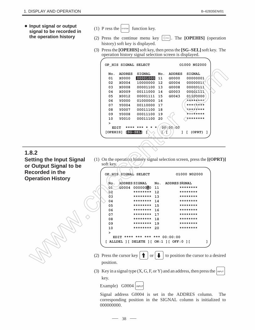
(1) P ress the SYSTEM function key.
(2) Press the continue menu key . The [OPEHIS] (operationhistory) soft key is displayed.
(3) Press the [OPEHIS] soft key, then press the [SG–SEL] soft key. Theoperation history signal selection screen is displayed.
(2) Press the cursor key or to position the cursor to a desired
position.
(3) Key in a signal type (X, G, F, or Y) and an address, then press the INPUT
key.
Example) G0004 INPUT
Signal address G0004 is set in the ADDRES column. Thecorresponding position in the SIGNAL column is initialized to000000000.
Input signal or outputsignal to be recorded inthe operation history
1.8.2Setting the Input Signalor Output Signal to beRecorded in theOperation History
www.cncc
enter
.com
B–62835EN/01 1. DISPLAY AND OPERATION
39
(4) Select the bit to be recorded.To select all bits of the specified signal address, press the [ON:1] softkey while the cursor is positioned to 00000000.
To select a particular bit, position the cursor to that bit by pressing the
cursor key or , then press the [ON:1] soft key. To cancel
a selection made by pressing the [ON:1] soft key or to cancel apreviously selected signal, press the [OFF:0] soft key.
(5) Up to 20 addresses can be specified by means of this signal selection.These addresses need not always be specified at consecutivepositions, starting from No.1.
(6) Pressing the [ALLDEL] and [EXEC] soft keys deletes all data. Ifthe [ALLDEL] key is pressed by mistake, it can be cancelled bypressing the [CAN] key.
(7) To delete a selected signal address, position the cursor to thecorresponding position then press the [DELETE] and [EXEC] softkeys. In the SIGNAL column, asterisks ******** are displayed inplace of the deleted data. In the ADDRES column, the correspondingposition is cleared.If the [DELET] key is pressed by mistake, it can be cancelled bypressing the [CAN] key.
(8) Pressing the return menu key [ ] causes the [OPEHIS] (operationhistory) soft key to be displayed again.
NOTE1 A cross (×) indicates that a signal will not be recorded. Also,
any signal for which an address is not specified will not berecorded, either.
2 A circle () indicates that a signal can be recorded.3 A signal indicated by its symbol name will also be displayed
by its symbol name.
Input signals and outputsignals to be recorded inthe history
www.cncc
enter
.com
1. DISPLAY AND OPERATION B–62835EN/01
40
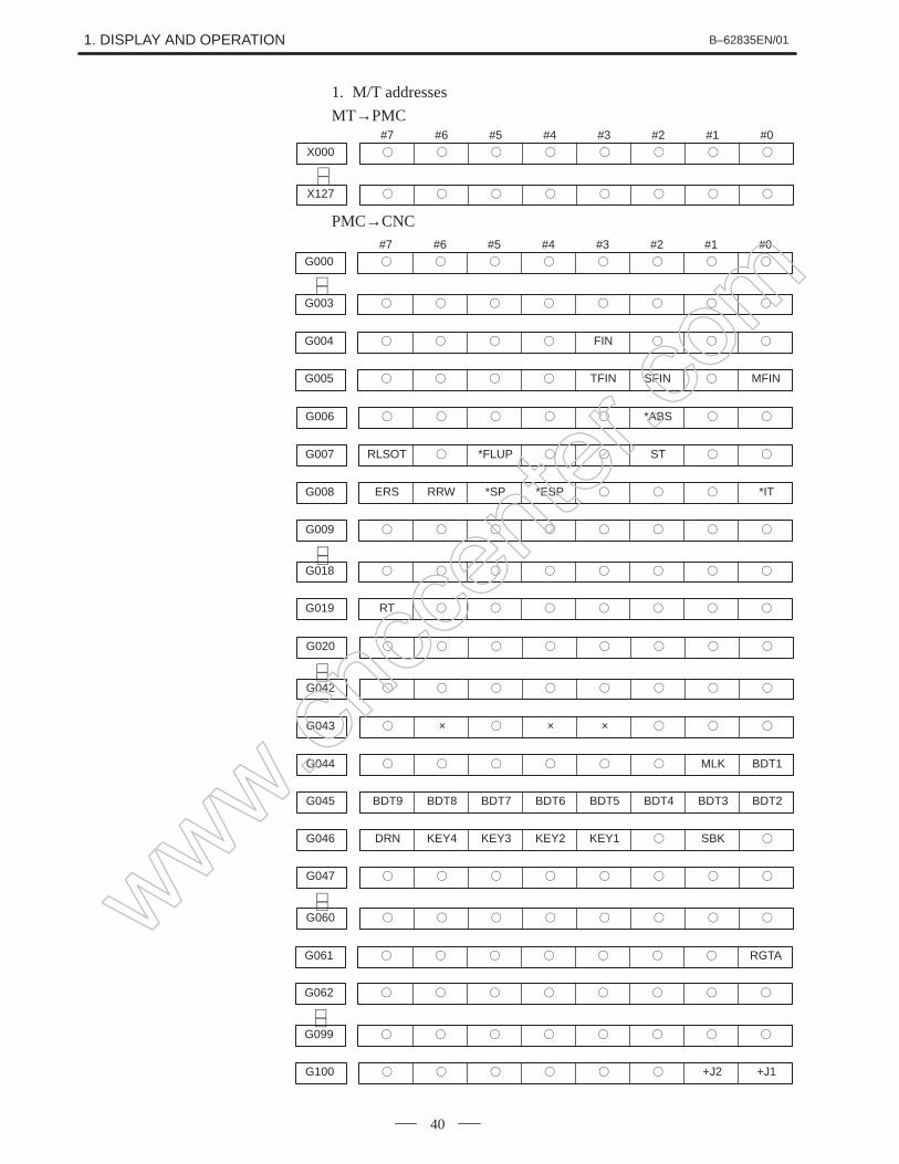
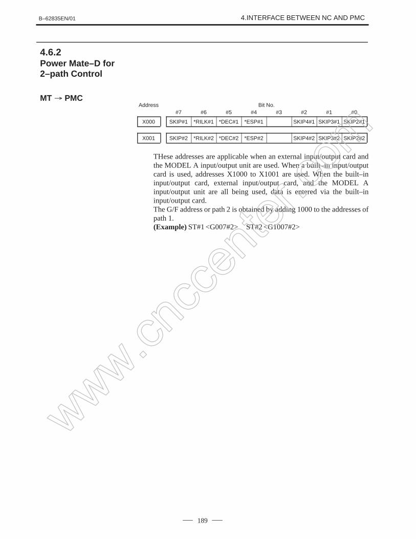
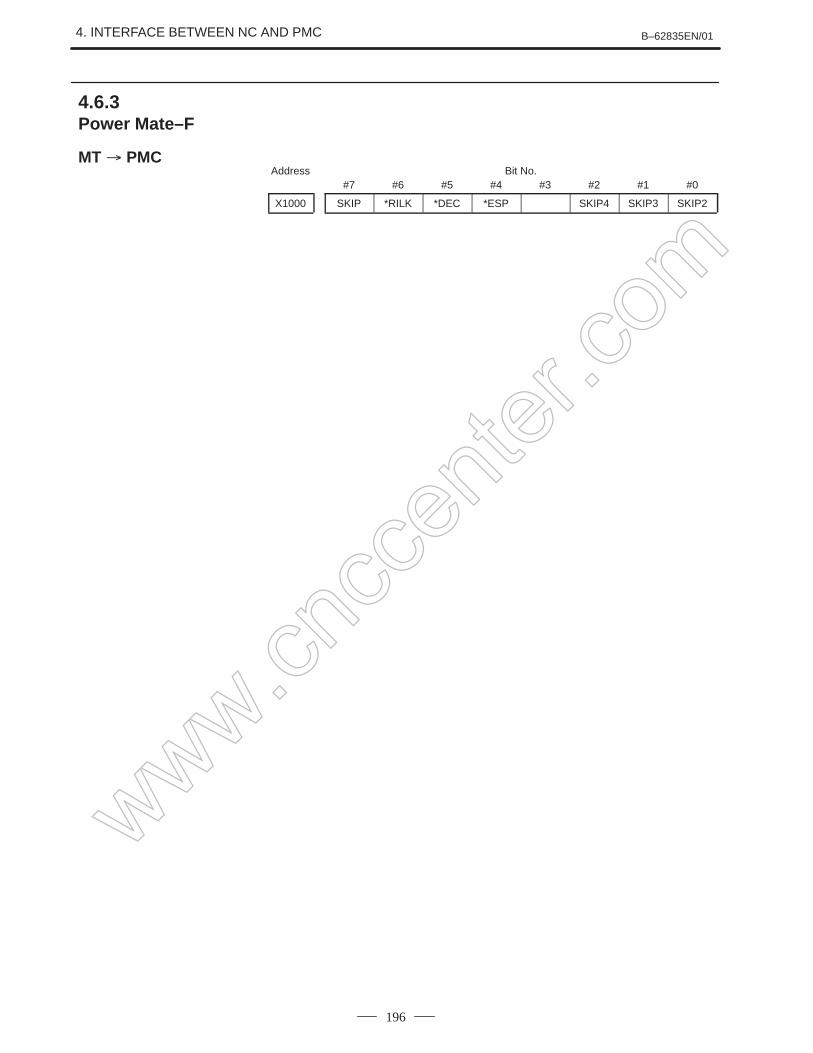
1. M/T addresses
MT→PMC#7X000
#6
#5
#4
#3
#2
#1
#0
X127
∼∼
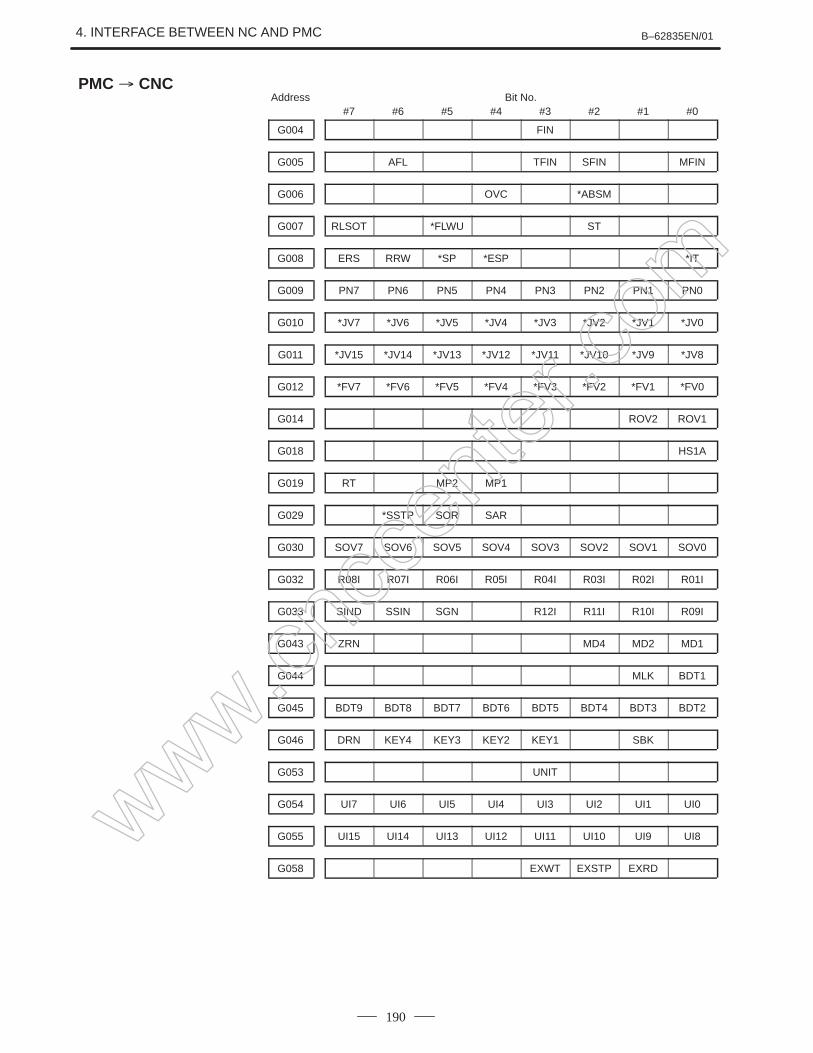
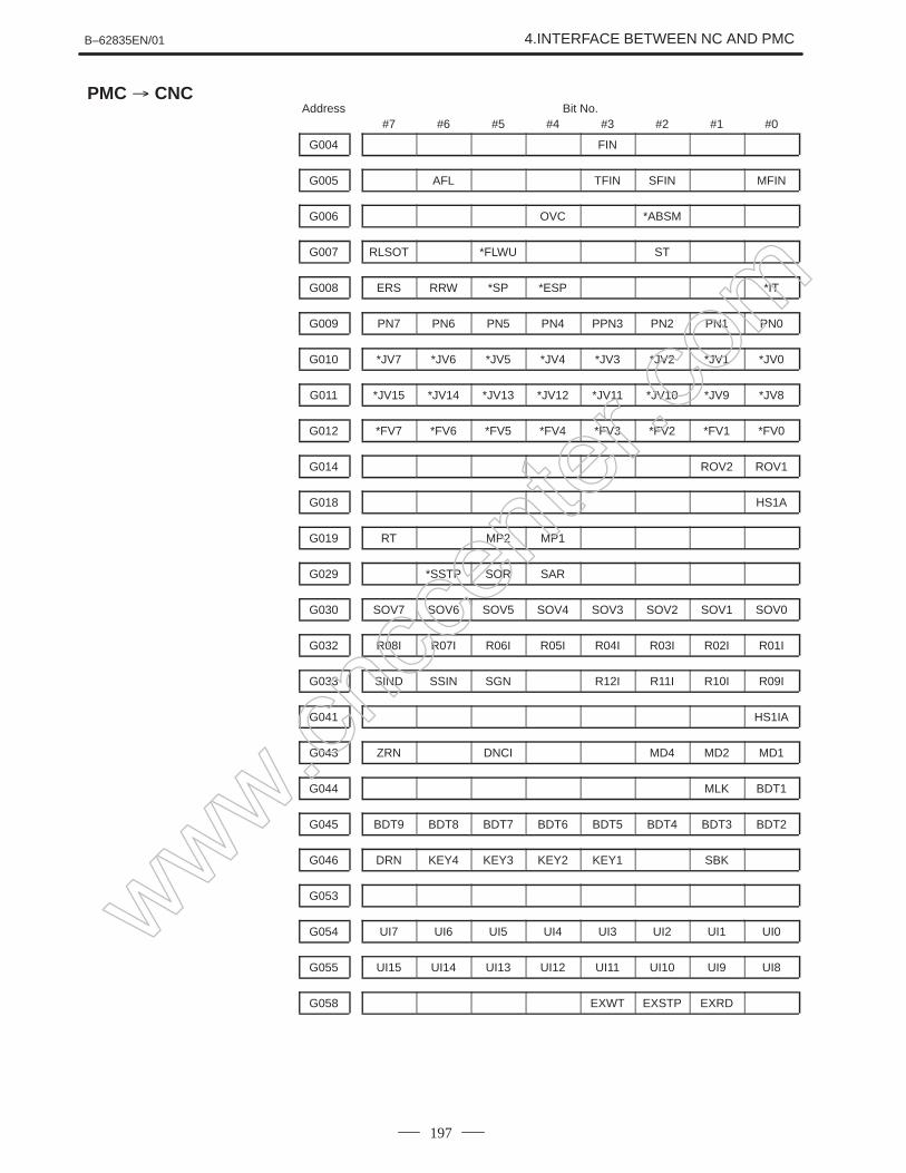
PMC→CNC#7G000
#6
#5
#4
#3
#2
#1
#0
G003
G004 FIN
G005 TFIN SFIN MFIN
∼∼
G006 *ABS
RLSOTG007 *FLUP ST
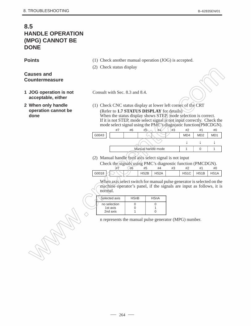
ERSG008 RRW *SP *ESP *IT
G009
G018
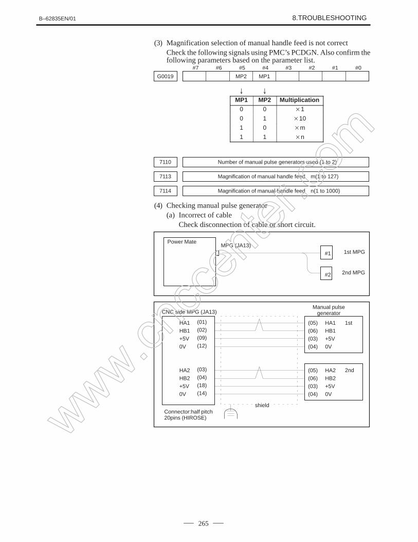
RTG019
∼∼
G020
G042
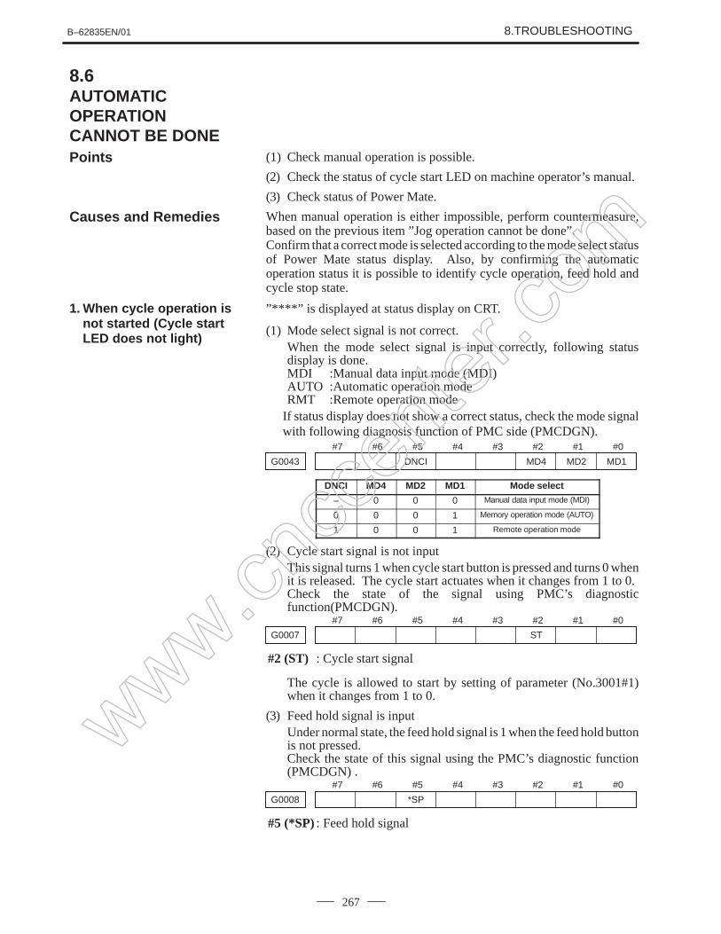
G043 × × ×
G044 MLK BDT1
BDT9G045 BDT8 BDT7 BDT6 BDT5 BDT4 BDT3 BDT2
DRNG046 KEY4 KEY3 KEY2 KEY1 SBK
G047
G060
∼∼∼∼
G061 RGTA
G062
G099
∼∼
G100 +J2 +J1
www.cncc
enter
.com
B–62835EN/01 1. DISPLAY AND OPERATION
41
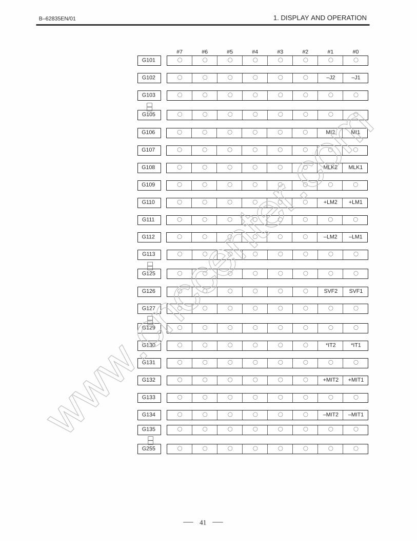
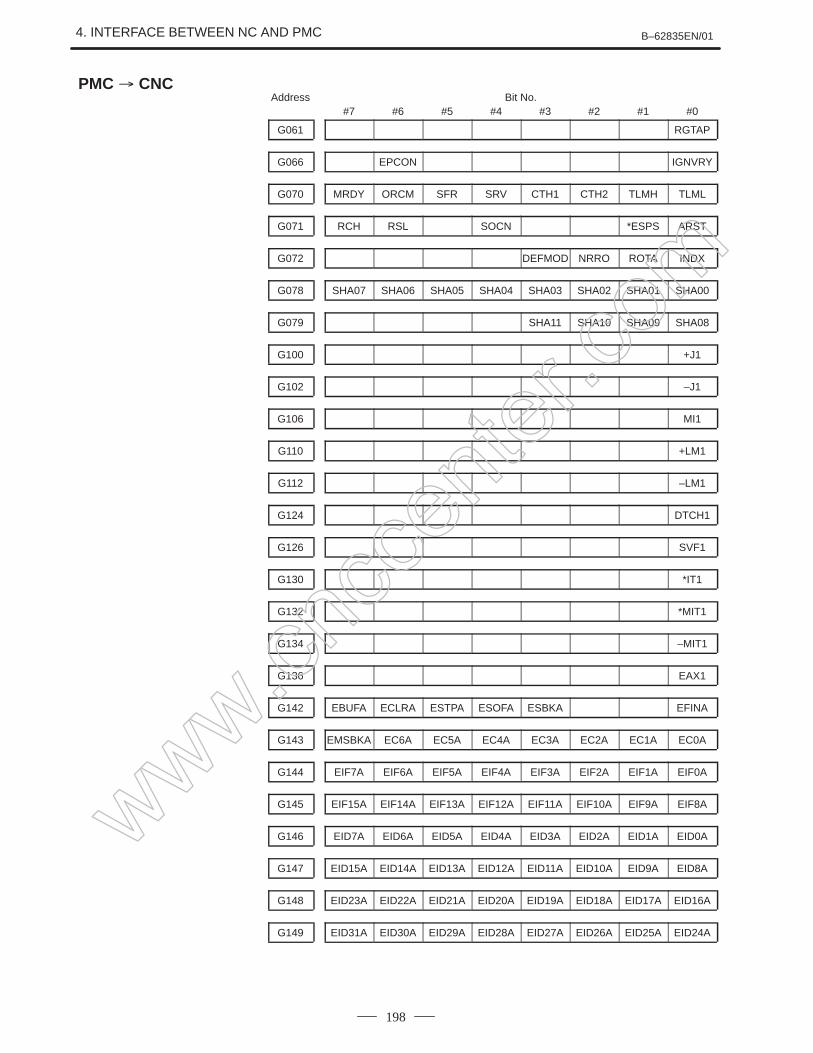
#7 #6 #5 #4 #3 #2 #1 #0
G101
G102 –J2 –J1
G103
G105
∼∼
G106 MI2 MI1
G107
G108 MLK2 MLK1
G109
G110 +LM2 +LM1
G111
G112 –LM2 –LM1
G113
G125
G126 SVF2 SVF1
G127
G129
G130 *IT2 *IT1
G131
G132 +MIT2 +MIT1
G133
G134 –MIT2 –MIT1
∼∼∼∼
G135
G255
∼∼www.cncc
enter
.com
1. DISPLAY AND OPERATION B–62835EN/01
42
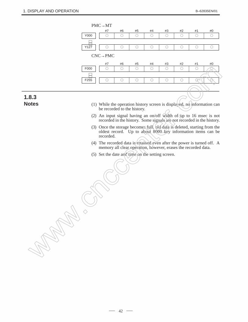
PMC→MT#7Y000
#6
#5
#4
#3
#2
#1
#0
Y127
∼∼
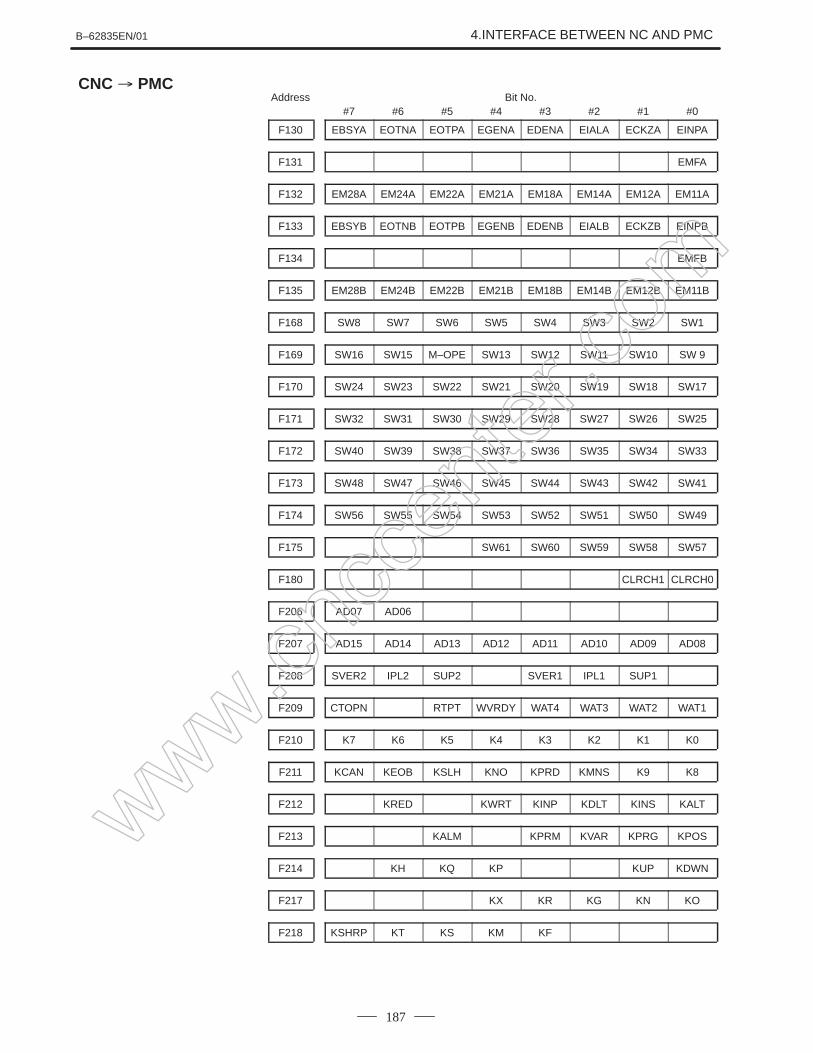
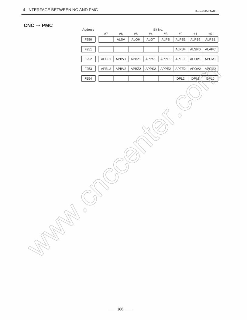
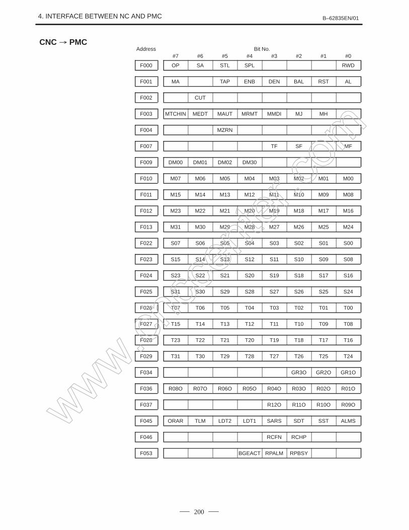
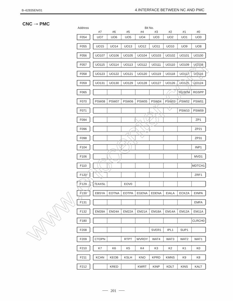
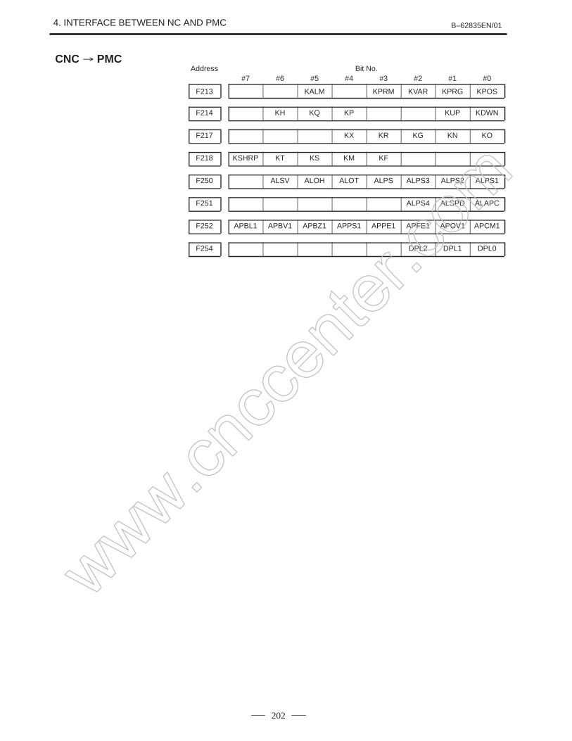
CNC→PMC
#7F000
#6
#5
#4
#3
#2
#1
#0
F255
∼∼
(1) While the operation history screen is displayed, no information canbe recorded to the history.
(2) An input signal having an on/off width of up to 16 msec is notrecorded in the history. Some signals are not recorded in the history.
(3) Once the storage becomes full, old data is deleted, starting from theoldest record. Up to about 8000 key information items can berecorded.
(4) The recorded data is retained even after the power is turned off. Amemory all clear operation, however, erases the recorded data.
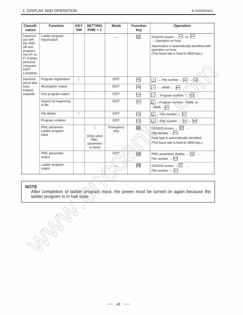
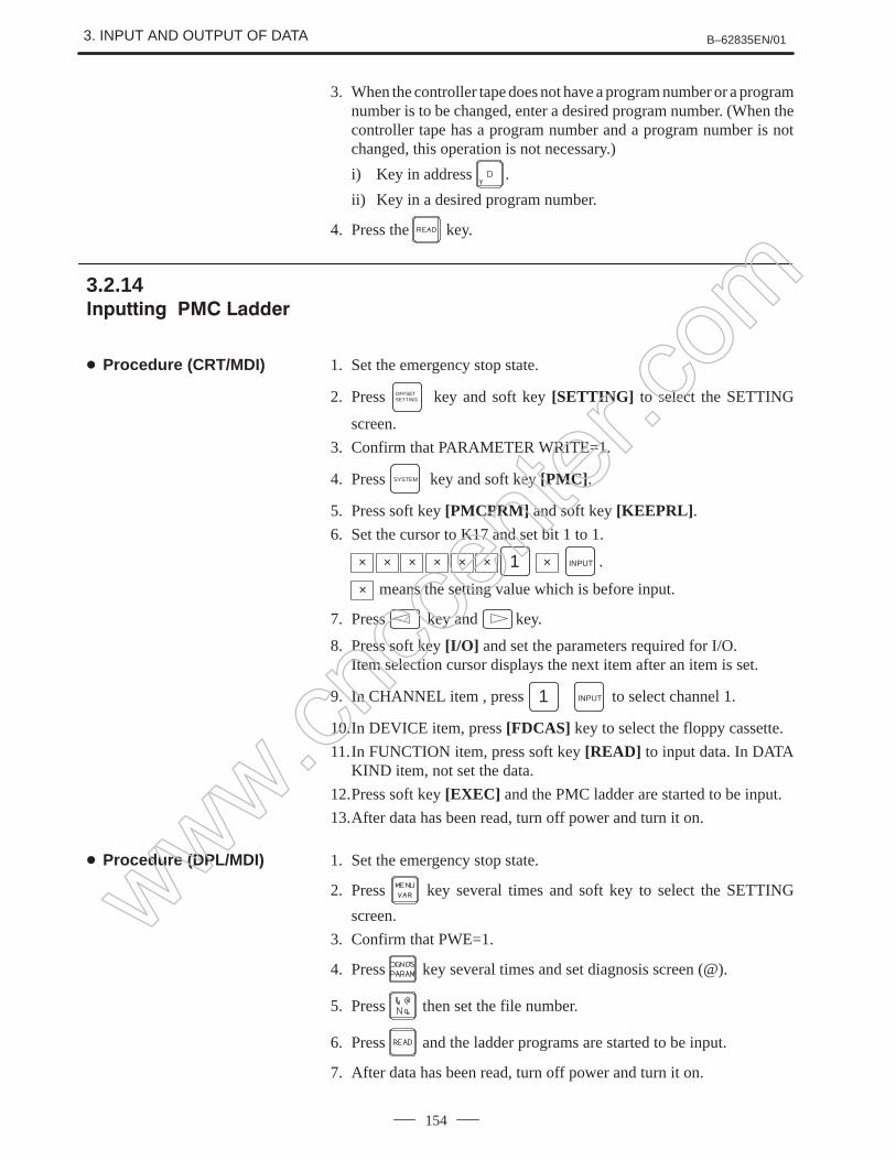
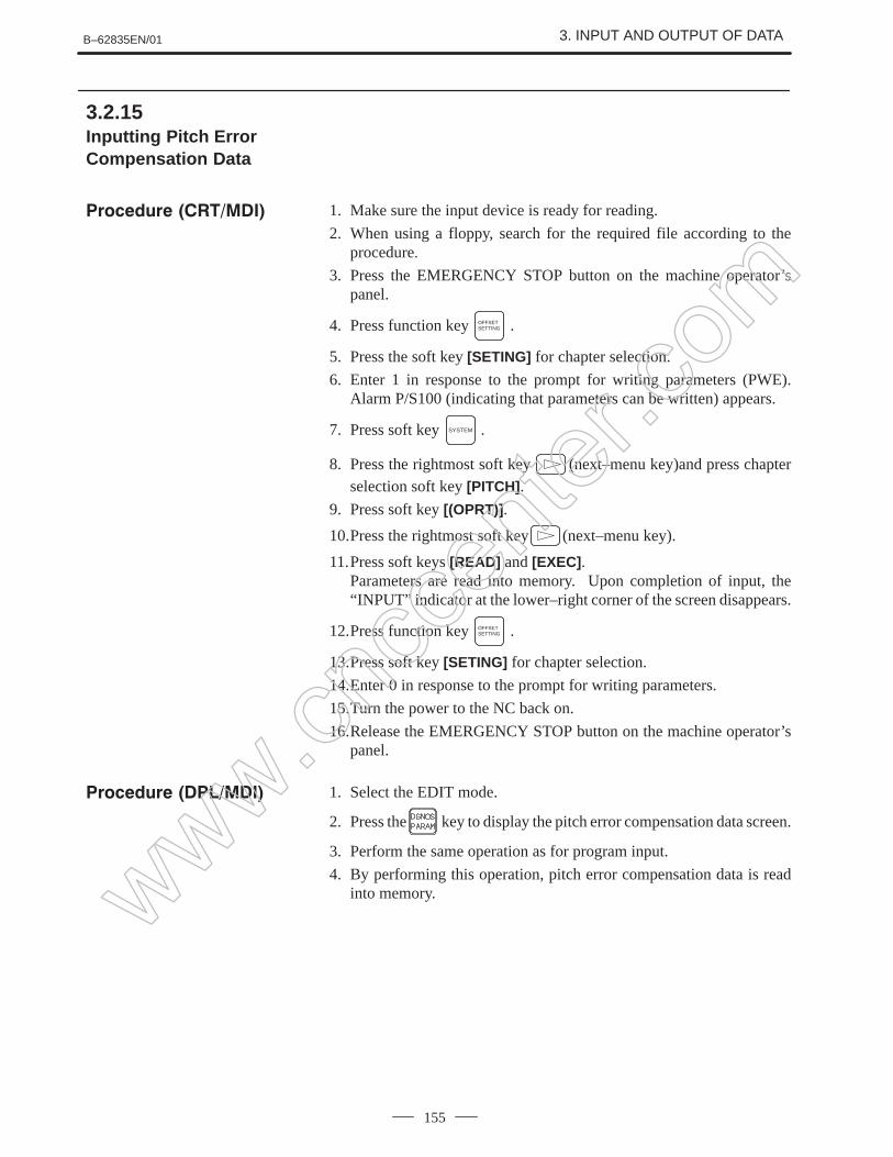
Input/output is automatically identified withoperation on host. (The baud rate is fixed to 9600 bps.)
Input/out-put to and
Program registration EDIT → File number → →ut to and
from FANUC
All program output EDIT → –9999 →FANUC cassette One program output EDIT → Program number →
Search for beginningof file
EDIT → Program number, –9999, or
–9998 →
File delete EDIT → File number →
Program collation EDIT → File number → →
PMC parameterLadder program input
Emergencystop
DGNOS screen → →File number → →input (Only when
PMC parameteris input)
File number → →Data type is automatically identified.
(The baud rate is fixed to 4800 bps.)
PMC parameter output
EDIT PMC parameter display → →File number →
Ladder program output
__ DGNOS screen → →File number →
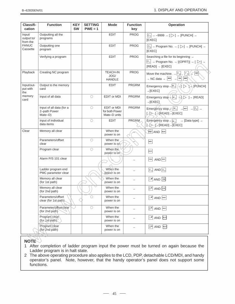
NOTEAfter completion of ladder program input, the power must be turned on again because theladder program is in halt state.
www.cncc
enter
.com
B–62835EN/01 1. DISPLAY AND OPERATION
49
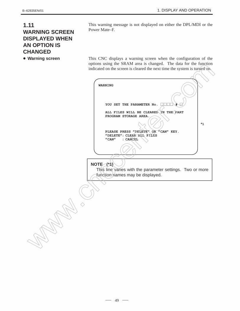
This warning message is not displayed on either the DPL/MDI or thePower Mate–F.
This CNC displays a warning screen when the configuration of theoptions using the SRAM area is changed. The data for the functionindicated on the screen is cleared the next time the system is turned on.
WARNING
YOU SET THE PARAMETER No. #
ALL FILES WILL BE CLEARED IN THE PARTPROGRAM STORAGE AREA.
PLEASE PRESS ”DELETE” OR ”CAN” KEY.”DELETE”: CLEAR ALL FILES”CAN” : CANCEL
*1
NOTE (*1)This line varies with the parameter settings. Two or morefunction names may be displayed.
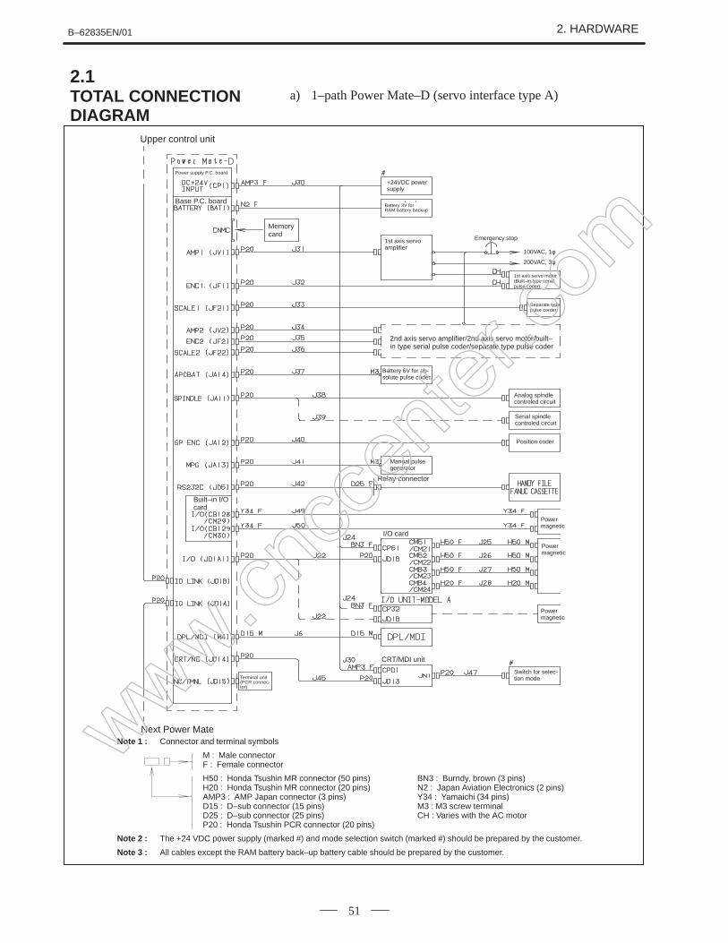
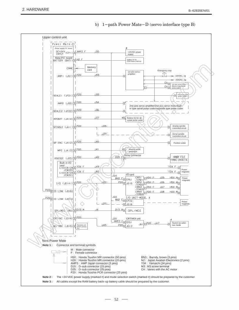
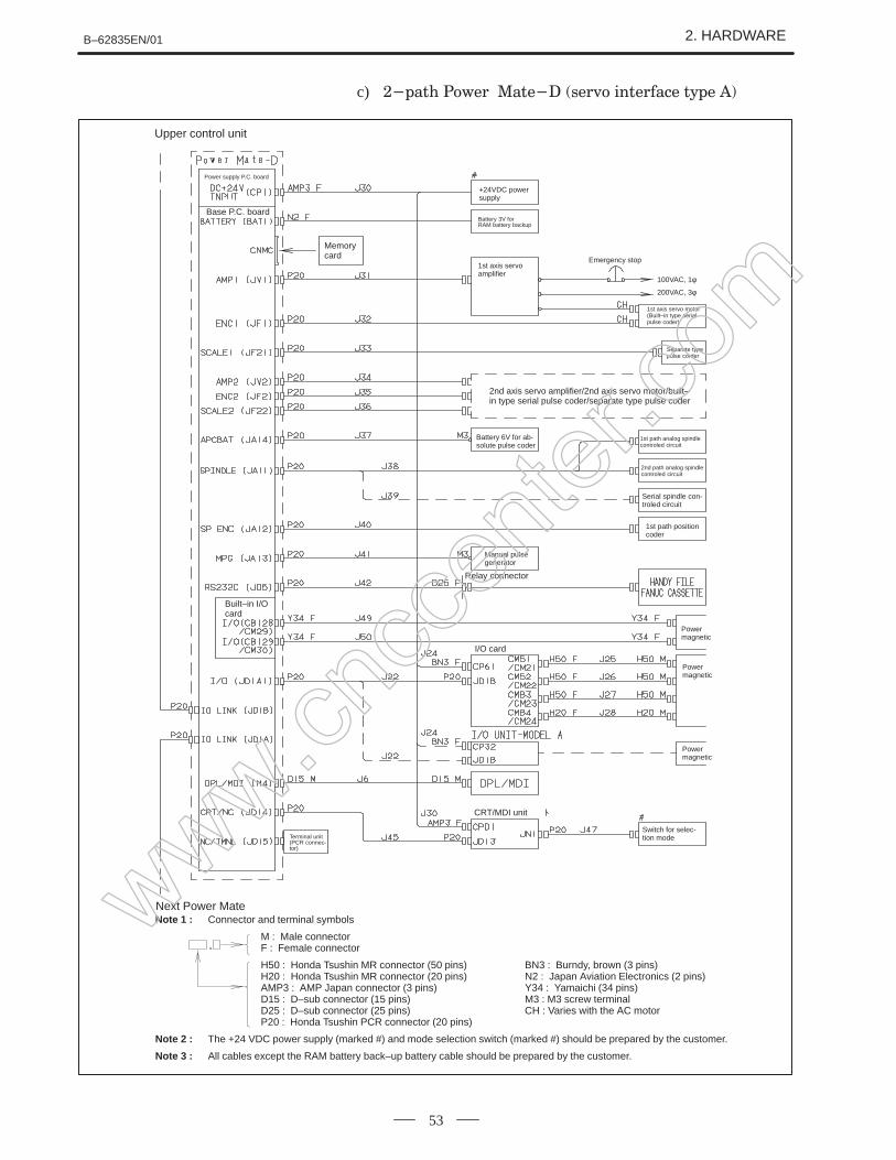
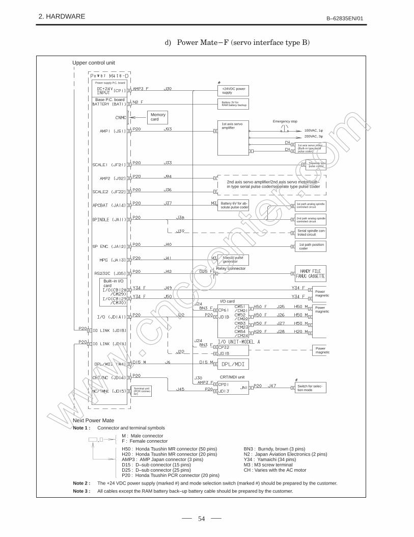
Note 2 : The +24 VDC power supply (marked #) and mode selection switch (marked #) should be prepared by the customer.
Note 3 : All cables except the RAM battery back–up battery cable should be prepared by the customer.
www.cncc
enter
.com
B–62835EN/01 2. HARDWARE
55
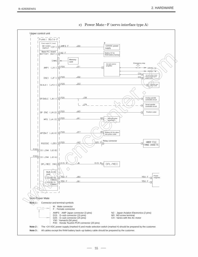
e)
Emergency stop
100VAC, 1φ
200VAC, 3φ
Separate typepulse corder
1st axis servo motor(Built–in type serial pulse coder)
Power supply P.C. board
Base P.C. board
Memorycard
+24VDC powersupply
Battery 3V for RAM battery backup
1st axis servo amplifier
Upper control unit
Analog spindlecontroled circuit
Serial spindlecontroled circuit
Position coder
Manual pulsegenerator
Battery 6V for abso-lute pulse coder
Relay connector
Powermagnetic
Built–in I/Ocard
Next Power Mate
Note 1 : Connector and terminal symbols
M : Male connectorF : Female connector
AMP3 : AMP Japan connector (3 pins) N2 : Japan Aviation Electronics (2 pins)D15 : D–sub connector (15 pins) M3 : M3 screw terminalD25 : D–sub connector (25 pins) CH : Varies with the AC motorY50 : Yamaichi (50 pins)P20 : Honda Tsushin PCR connector (20 pins)
Note 2 : The +24 VDC power supply (marked #) and mode selection switch (marked #) should be prepared by the customer.
Note 3 : All cables except the RAM battery back–up battery cable should be prepared by the customer.
www.cncc
enter
.com
2. HARDWARE B–62835EN/01
56
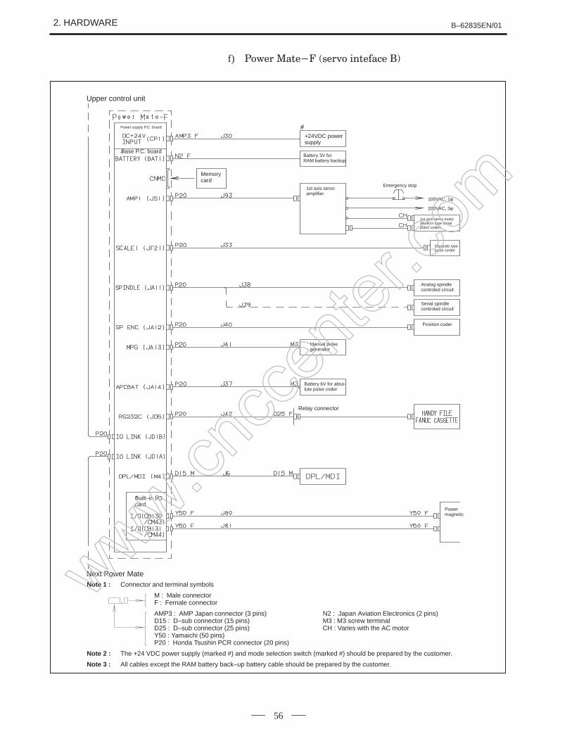
f)
Emergency stop
100VAC, 1φ
200VAC, 3φ
Separate type pulse corder
1st axis servo motor(Built–in type serial pulse coder)
Power supply P.C. board
Base P.C. board
Memorycard
+24VDC powersupply
Battery 3V for RAM battery backup
1st axis servo amplifier
Upper control unit
Analog spindlecontroled circuit
Serial spindlecontroled circuit
Position coder
Manual pulsegenerator
Battery 6V for abso-lute pulse coder
Relay connector
Powermagnetic
Built–in I/Ocard
Next Power MateNote 1 : Connector and terminal symbols
M : Male connectorF : Female connector
AMP3 : AMP Japan connector (3 pins) N2 : Japan Aviation Electronics (2 pins)D15 : D–sub connector (15 pins) M3 : M3 screw terminalD25 : D–sub connector (25 pins) CH : Varies with the AC motorY50 : Yamaichi (50 pins)P20 : Honda Tsushin PCR connector (20 pins)
Note 2 : The +24 VDC power supply (marked #) and mode selection switch (marked #) should be prepared by the customer.
Note 3 : All cables except the RAM battery back–up battery cable should be prepared by the customer.
www.cncc
enter
.com
B–62835EN/01 2. HARDWARE
57
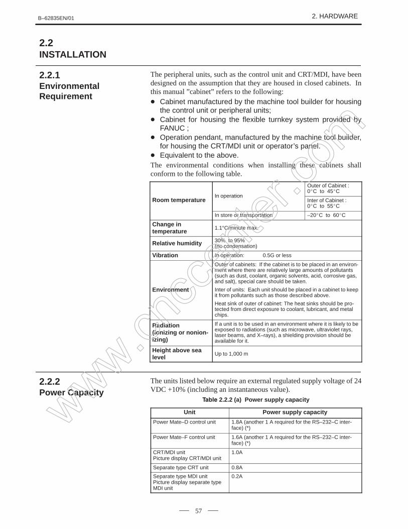
The peripheral units, such as the control unit and CRT/MDI, have beendesigned on the assumption that they are housed in closed cabinets. Inthis manual ”cabinet” refers to the following: Cabinet manufactured by the machine tool builder for housing
the control unit or peripheral units; Cabinet for housing the flexible turnkey system provided by
FANUC ; Operation pendant, manufactured by the machine tool builder,
for housing the CRT/MDI unit or operator’s panel. Equivalent to the above.The environmental conditions when installing these cabinets shallconform to the following table.
In operation
Outer of Cabinet :0C to 45C
Room temperatureIn o eration
Inter of Cabinet :0C to 55C
In store or transportation –20C to 60C
Change in temperature
1.1°C/minute max.
Relative humidity 30% to 95%(no condensation)
Vibration In operation: 0.5G or less
Environment
Outer of cabinets: If the cabinet is to be placed in an environ-ment where there are relatively large amounts of pollutants(such as dust, coolant, organic solvents, acid, corrosive gas,and salt), special care should be taken.
Inter of units: Each unit should be placed in a cabinet to keepit from pollutants such as those described above.
Heat sink of outer of cabinet: The heat sinks should be pro-tected from direct exposure to coolant, lubricant, and metalchips.
Radiation (ionizing or nonion-izing)
If a unit is to be used in an environment where it is likely to beexposed to radiations (such as microwave, ultraviolet rays,laser beams, and X–rays), a shielding provision should beavailable for it.
Height above sealevel
Up to 1,000 m
The units listed below require an external regulated supply voltage of 24VDC +10% (including an instantaneous value).
2.2.2 (a) Power supply capacity
Unit Power supply capacity
Power Mate–D control unit 1.8A (another 1 A required for the RS–232–C inter-face) (*)
Power Mate–F control unit 1.6A (another 1 A required for the RS–232–C inter-face) (*)
CRT/MDI unitPicture display CRT/MDI unit
1.0A
Separate type CRT unit 0.8A
Separate type MDI unit Picture display separate typeMDI unit
0.2A
2.2INSTALLATION
2.2.1EnvironmentalRequirement
2.2.2Power Capacity
www.cncc
enter
.com
2. HARDWARE B–62835EN/01
58
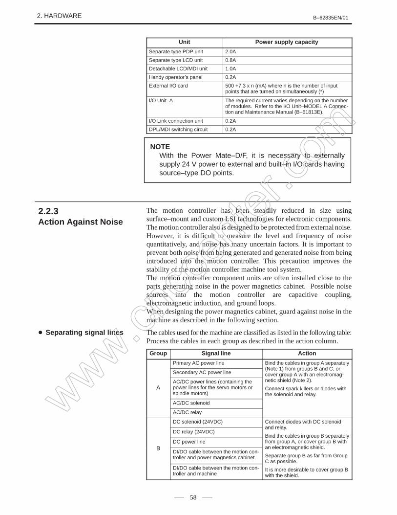
Unit Power supply capacity
Separate type PDP unit 2.0A
Separate type LCD unit 0.8A
Detachable LCD/MDI unit 1.0A
Handy operator’s panel 0.2A
External I/O card 500 +7.3 x n (mA) where n is the number of inputpoints that are turned on simultaneously (*)
I/O Unit–A The required current varies depending on the numberof modules. Refer to the I/O Unit–MODEL A Connec-tion and Maintenance Manual (B–61813E).
I/O Link connection unit 0.2A
DPL/MDI switching circuit 0.2A
NOTEWith the Power Mate–D/F, it is necessary to externallysupply 24 V power to external and built–in I/O cards havingsource–type DO points.
The motion controller has been steadily reduced in size usingsurface–mount and custom LSI technologies for electronic components.The motion controller also is designed to be protected from external noise.However, it is difficult to measure the level and frequency of noisequantitatively, and noise has many uncertain factors. It is important toprevent both noise from being generated and generated noise from beingintroduced into the motion controller. This precaution improves thestability of the motion controller machine tool system.The motion controller component units are often installed close to theparts generating noise in the power magnetics cabinet. Possible noisesources into the motion controller are capacitive coupling,electromagnetic induction, and ground loops.When designing the power magnetics cabinet, guard against noise in themachine as described in the following section.
The cables used for the machine are classified as listed in the following table:Process the cables in each group as described in the action column.
Group Signal line Action
Primary AC power line Bind the cables in group A separately(Note 1) from groups B and C or
Secondary AC power line(Note 1) from groups B and C, orcover group A with an electromag-
AAC/DC power lines (containing thepower lines for the servo motors orspindle motors)
g gnetic shield (Note 2).
Connect spark killers or diodes withthe solenoid and relay.
AC/DC solenoid
AC/DC relay
DC solenoid (24VDC) Connect diodes with DC solenoidand relay
DC relay (24VDC)and relay.
Bind the cables in group B separately
BDC power line
Bind the cables in grou B se aratelyfrom group A, or cover group B withan electromagnetic shieldB
DI/DO cable between the motion con-troller and power magnetics cabinet
an electromagnetic shield.
Separate group B as far from GroupC as possible.
DI/DO cable between the motion con-troller and machine
C as oss b e
It is more desirable to cover group Bwith the shield.
2.2.3Action Against Noise
Separating signal lines
www.cncc
enter
.com
B–62835EN/01 2. HARDWARE
59
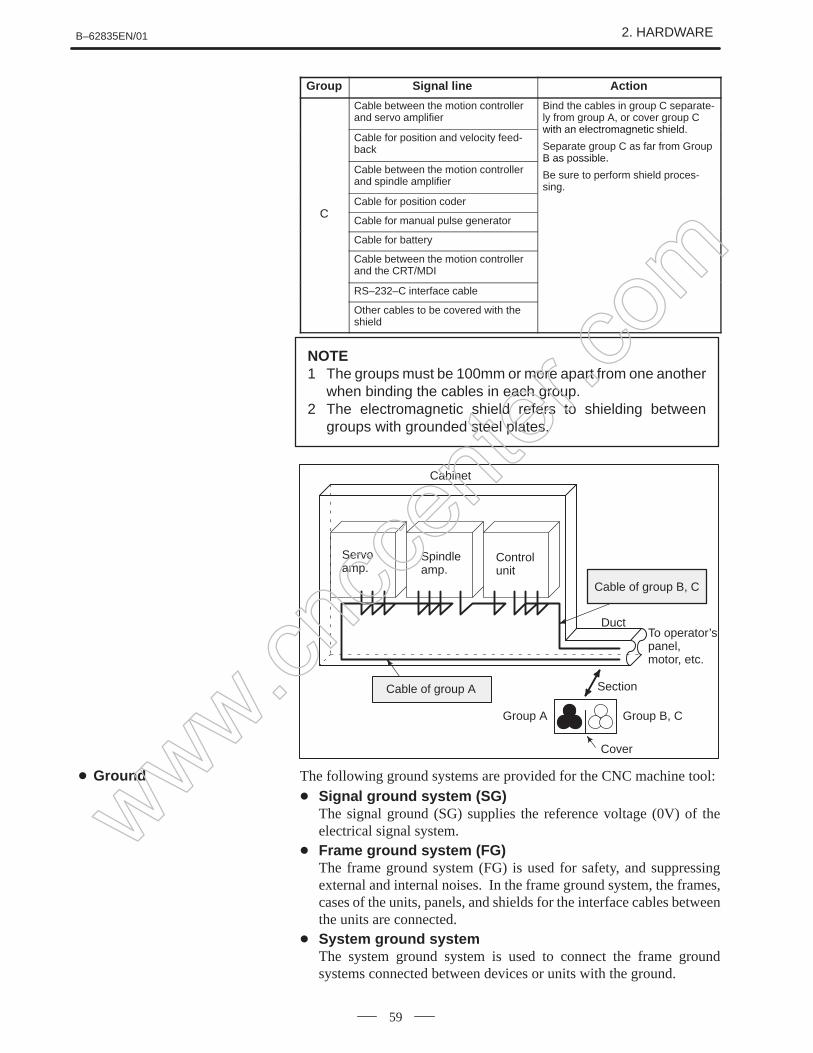
Group ActionSignal line
Cable between the motion controllerand servo amplifier
Bind the cables in group C separate-ly from group A, or cover group Cwith an electromagnetic shield
Cable for position and velocity feed-back
with an electromagnetic shield.
Separate group C as far from GroupB as possible.
Cable between the motion controllerand spindle amplifier
B as ossible.
Be sure to perform shield proces-sing.
CCable for position coder
g
CCable for manual pulse generator
Cable for battery
Cable between the motion controllerand the CRT/MDI
RS–232–C interface cable
Other cables to be covered with theshield
NOTE1 The groups must be 100mm or more apart from one another
when binding the cables in each group.2 The electromagnetic shield refers to shielding between
groups with grounded steel plates.
Cable of group B, C
Cable of group A
Cabinet
Servo amp.
Spindleamp.
Control unit
DuctTo operator’s panel, motor, etc.
Section
Group A Group B, C
Cover
The following ground systems are provided for the CNC machine tool:
Signal ground system (SG)The signal ground (SG) supplies the reference voltage (0V) of theelectrical signal system.
Frame ground system (FG)The frame ground system (FG) is used for safety, and suppressingexternal and internal noises. In the frame ground system, the frames,cases of the units, panels, and shields for the interface cables betweenthe units are connected.
System ground systemThe system ground system is used to connect the frame groundsystems connected between devices or units with the ground.
Ground
www.cncc
enter
.com
2. HARDWARE B–62835EN/01
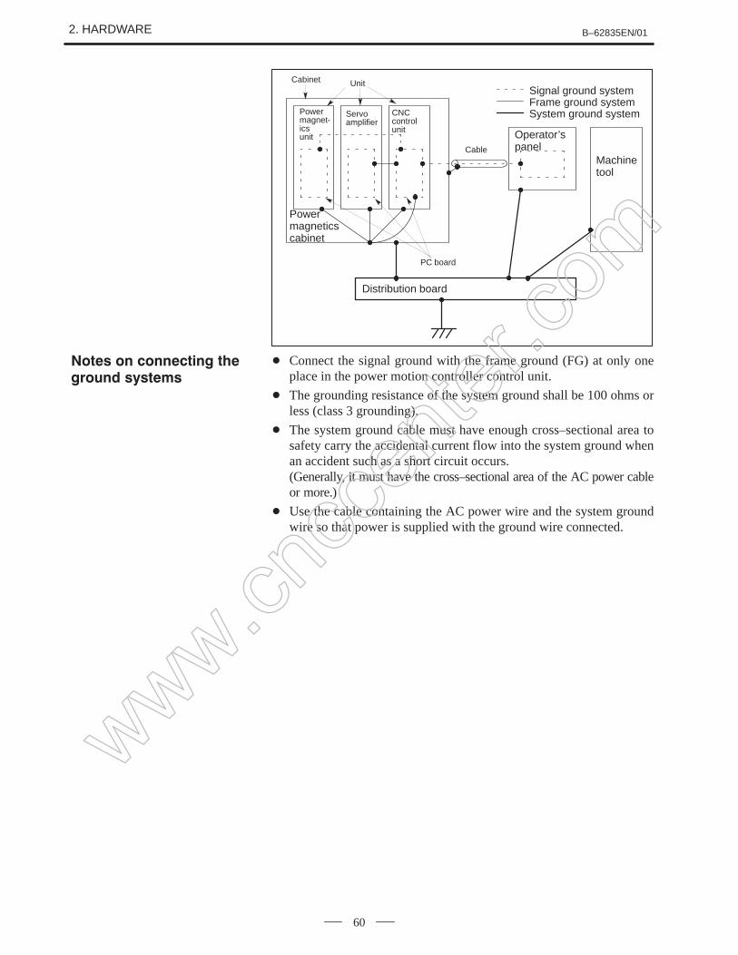
60
Power magnet-ics unit
Servoamplifier
CNCcontrol unit
Powermagneticscabinet
Distribution board
Operator’spanel
Machinetool
System ground systemFrame ground systemSignal ground system
Unit
Cable
PC board
Cabinet
Connect the signal ground with the frame ground (FG) at only oneplace in the power motion controller control unit.
The grounding resistance of the system ground shall be 100 ohms orless (class 3 grounding).
The system ground cable must have enough cross–sectional area tosafety carry the accidental current flow into the system ground whenan accident such as a short circuit occurs.(Generally, it must have the cross–sectional area of the AC power cableor more.)
Use the cable containing the AC power wire and the system groundwire so that power is supplied with the ground wire connected.
www.cncc
enter
.com
B–62835EN/01 2. HARDWARE
61
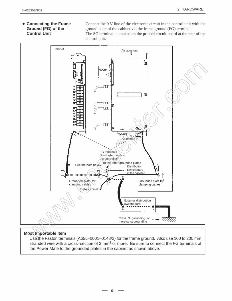
Connect the 0 V line of the electronic circuit in the control unit with theground plate of the cabinet via the frame ground (FG) terminal.The SG terminal is located on the printed circuit board at the rear of thecontrol unit.
Cabinet Air goes out.
FG terminals(Faston terminals atthe controller)
To the other grounded platesDistributionswitchboardin the cabinet
External distributionswitchboard
See the note below.
Class 3 grounding ormore strict grounding
To the cabinet
Grounded plate forclamping cables
Grounded plate forclamping cables
Air comes in.
Most Importable ItemUse the Faston terminals (A65L–0001–0148/2) for the frame ground. Also use 100 to 300 mmstranded wire with a cross–section of 2 mm2 or more. Be sure to connect the FG terminals ofthe Power Mate to the grounded plates in the cabinet as shown above.
Connecting the FrameGround (FG) of theControl Unit
www.cncc
enter
.com
2. HARDWARE B–62835EN/01
62
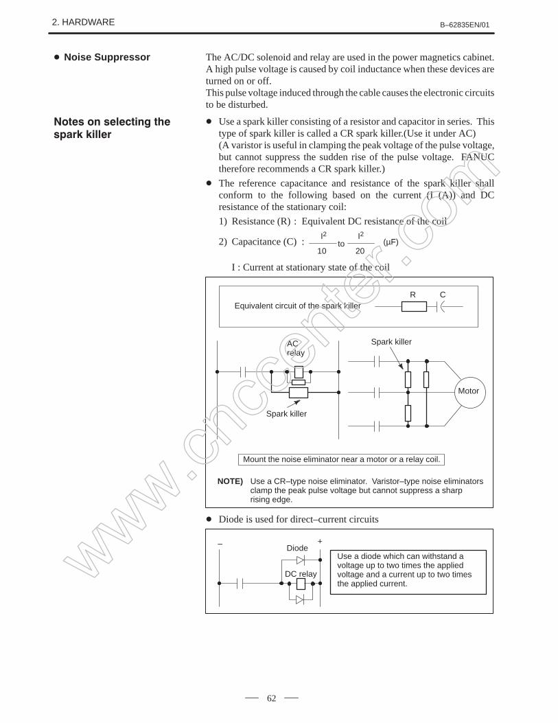
The AC/DC solenoid and relay are used in the power magnetics cabinet.A high pulse voltage is caused by coil inductance when these devices areturned on or off.This pulse voltage induced through the cable causes the electronic circuitsto be disturbed.
Use a spark killer consisting of a resistor and capacitor in series. Thistype of spark killer is called a CR spark killer.(Use it under AC)(A varistor is useful in clamping the peak voltage of the pulse voltage,but cannot suppress the sudden rise of the pulse voltage. FANUCtherefore recommends a CR spark killer.)
The reference capacitance and resistance of the spark killer shallconform to the following based on the current (I (A)) and DCresistance of the stationary coil:
1) Resistance (R) : Equivalent DC resistance of the coil
2) Capacitance (C) :20
I2(µF)to
I2
10
I : Current at stationary state of the coil
Equivalent circuit of the spark killerR C
Spark killer
Spark killer
Motor
ACrelay
Mount the noise eliminator near a motor or a relay coil.
NOTE) Use a CR–type noise eliminator. Varistor–type noise eliminatorsclamp the peak pulse voltage but cannot suppress a sharp rising edge.
Diode is used for direct–current circuits
Use a diode which can withstand avoltage up to two times the appliedvoltage and a current up to two timesthe applied current.
Diode
DC relay
– +
Noise Suppressor
www.cncc
enter
.com
B–62835EN/01 2. HARDWARE
63
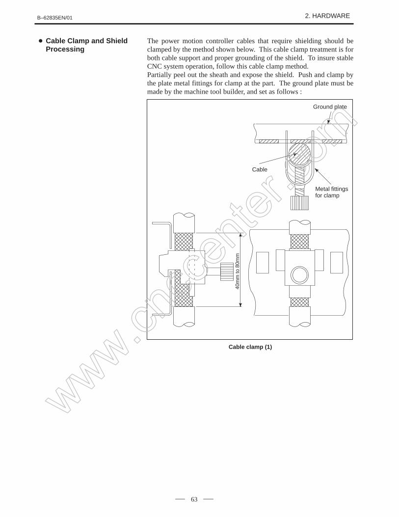
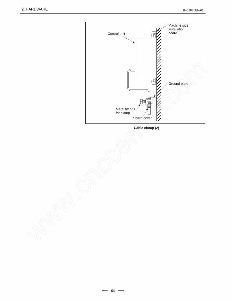
The power motion controller cables that require shielding should beclamped by the method shown below. This cable clamp treatment is forboth cable support and proper grounding of the shield. To insure stableCNC system operation, follow this cable clamp method.Partially peel out the sheath and expose the shield. Push and clamp bythe plate metal fittings for clamp at the part. The ground plate must bemade by the machine tool builder, and set as follows :
Cable
Metal fittings for clamp
Ground plate
40m
m to
80m
m
Cable clamp (1)
Cable Clamp and ShieldProcessing
www.cncc
enter
.com
2. HARDWARE B–62835EN/01
64
ÇÇÇÇÇÇÇÇÇÇÇÇÇÇÇÇÇÇÇÇÇÇÇÇÇÇÇÇÇÇÇÇ
Control unit
Ground plate
Metal fittings for clamp
Shield cover
Machine sideinstallationboard
Cable clamp (2)
www.cncc
enter
.com
B–62835EN/01 2. HARDWARE
65
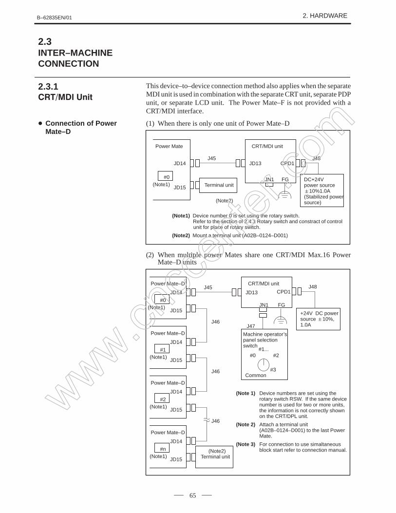
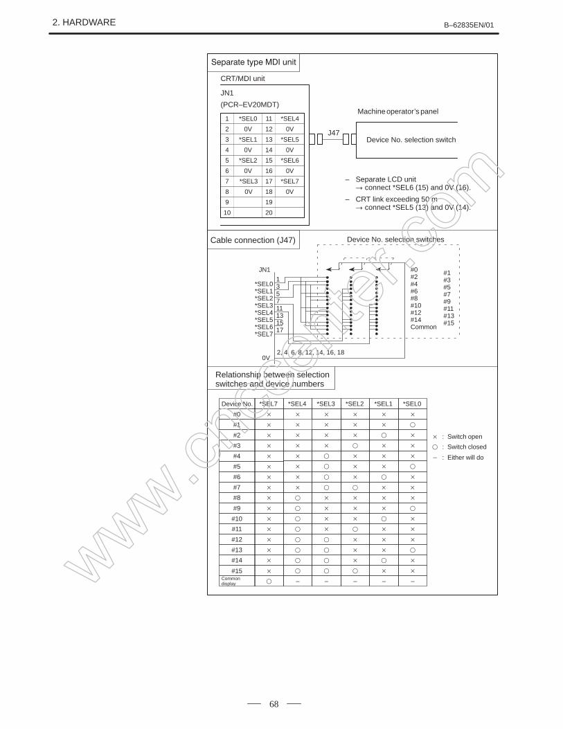
This device–to–device connection method also applies when the separateMDI unit is used in combination with the separate CRT unit, separate PDPunit, or separate LCD unit. The Power Mate–F is not provided with aCRT/MDI interface.
(Note1) Device number 0 is set using the rotary switch. Refer to the section of 2.4.1 Rotary switch and constract of control unit for place of rotary switch.
(Note2) Mount a terminal unit (A02B–0124–D001)
(2) When multiple power Mates share one CRT/MDI Max.16 PowerMate–D units
Power Mate–D
JD14 JD13
JD15
#0(Note1)
J45CRT/MDI unit
CPD1J48
JN1 FG
+24V DC powersource 10%,1.0A
(Note 1) Device numbers are set using the rotary switch RSW. If the same device number is used for two or more units, the information is not correctly shown on the CRT/DPL unit.
(Note 2) Attach a terminal unit (A02B–0124–D001) to the last Power Mate.
(Note 3) For connection to use simaltaneous block start refer to connection manual.
Terminal unit
Power Mate–D
JD14
JD15
#1(Note1)
J46
Power Mate–D
JD14
JD15
#2(Note1)
J46
Power Mate–D
JD14
JD15
#n(Note1)
J46
(Note2)
Machine operator’spanel selectionswitch
#1...#0 #2
Common
J47
#3
2.3INTER–MACHINECONNECTION
2.3.1
Connection of PowerMate–D
www.cncc
enter
.com
2. HARDWARE B–62835EN/01
66
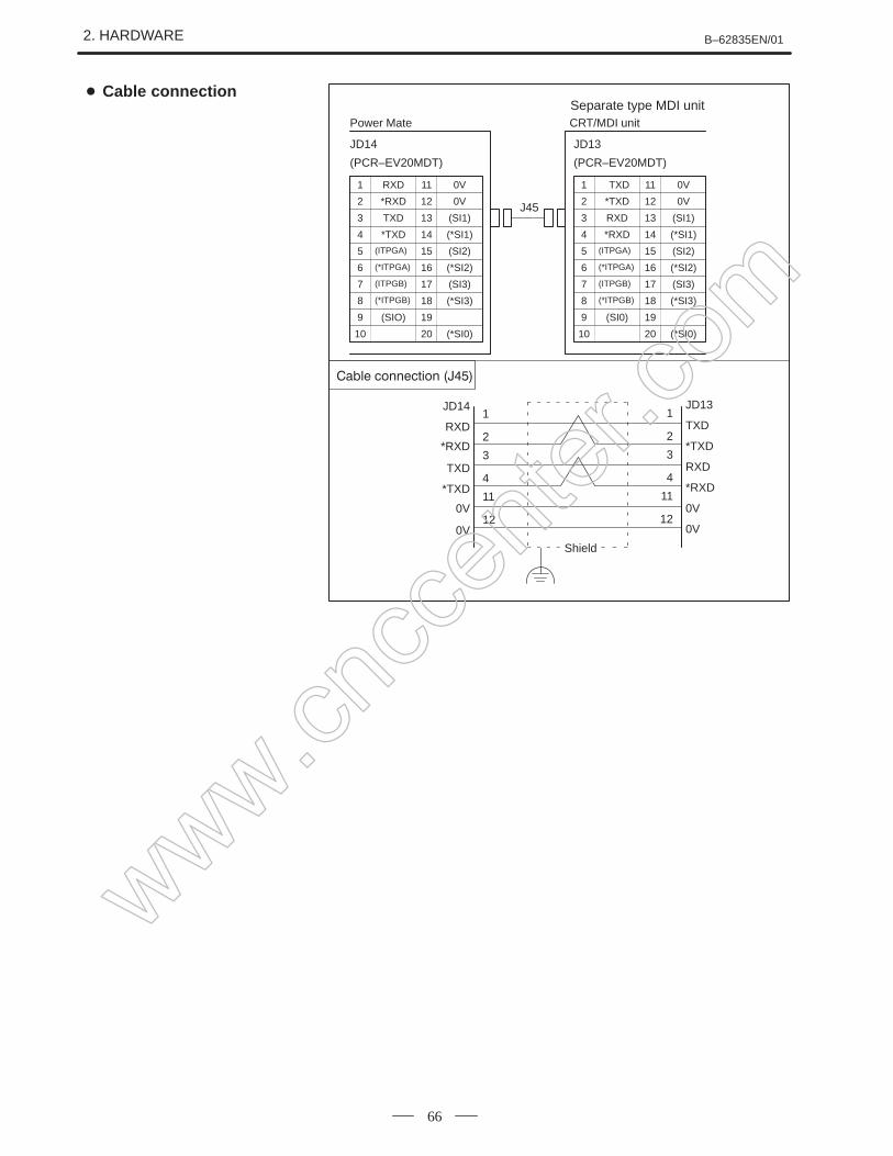
1 RXD
2 *RXD
3 TXD
4 *TXD
11 0V
12 0V
13 (SI1)
14 (*SI1)
5 (ITPGA)
6 (*ITPGA)
7 (ITPGB)
8 (*ITPGB)
15 (SI2)
16 (*SI2)
17 (SI3)
18 (*SI3)
9 (SIO)
10
19
20 (*SI0)
Power Mate
JD14
(PCR–EV20MDT)
CRT/MDI unit
JD13
(PCR–EV20MDT)
1
2
1
2RXD TXD
3
4
3
4
11
12
11
12
*RXD
TXD
*TXD
0V
0V
*TXD
RXD
*RXD
0V
0V
1 TXD
2 *TXD
3 RXD
4 *RXD
11 0V
12 0V
13 (SI1)
14 (*SI1)
5 (ITPGA)
6 (*ITPGA)
7 (ITPGB)
8 (*ITPGB)
15 (SI2)
16 (*SI2)
17 (SI3)
18 (*SI3)
9 (SI0)
10
19
20 (*SI0)
J45
JD14 JD13
Shield
Separate type MDI unit Cable connection
www.cncc
enter
.com
B–62835EN/01 2. HARDWARE
67
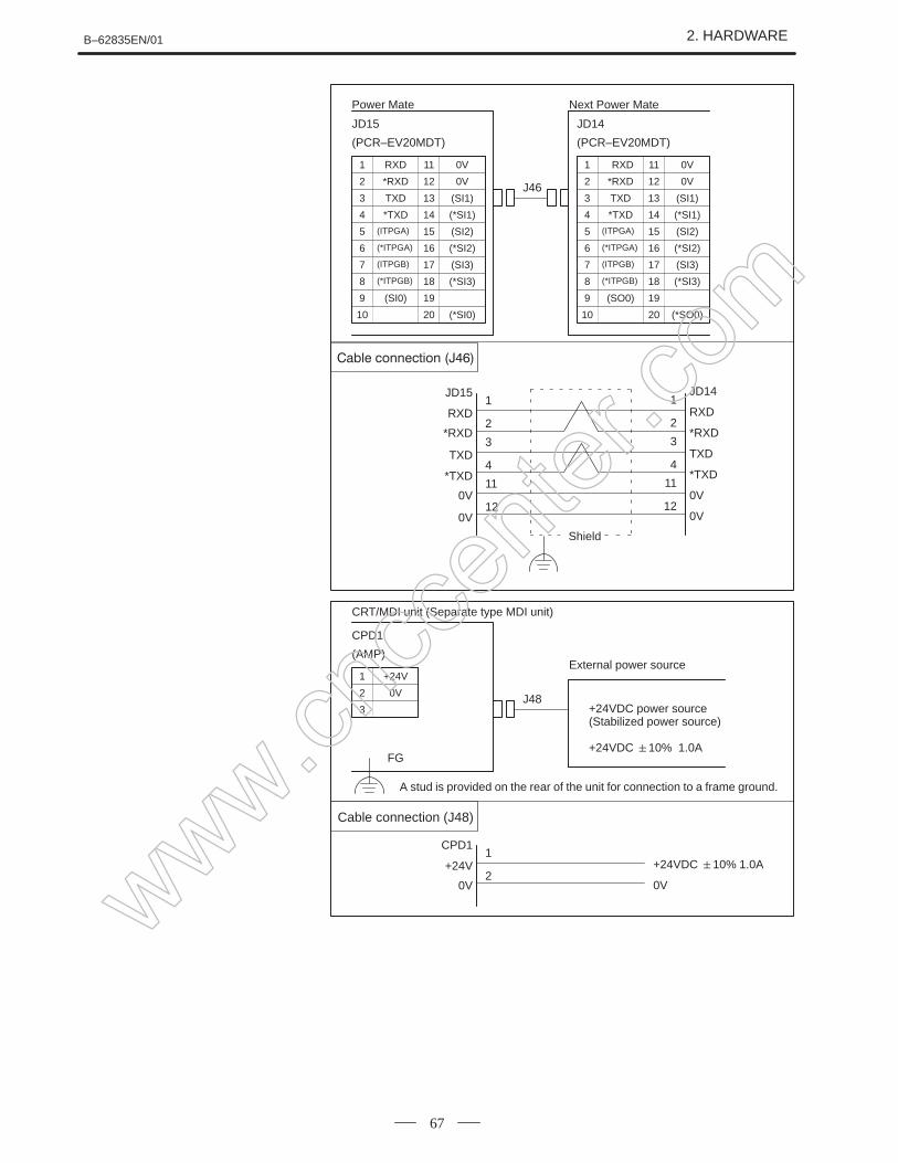
1 RXD
2 *RXD
3 TXD
4 *TXD
11 0V
12 0V
13 (SI1)
14 (*SI1)
5 (ITPGA)
6 (*ITPGA)
7 (ITPGB)
8 (*ITPGB)
15 (SI2)
16 (*SI2)
17 (SI3)
18 (*SI3)
9 (SI0)
10
19
20 (*SI0)
Power Mate
JD15
(PCR–EV20MDT)
JD14
(PCR–EV20MDT)
1
2
1
2RXD RXD
3
4
3
4
11
12
11
12
*RXD
TXD
*TXD
0V
0V
*RXD
TXD
*TXD
0V
0V
1 RXD
2 *RXD
3 TXD
4 *TXD
11 0V
12 0V
13 (SI1)
14 (*SI1)
5 (ITPGA)
6 (*ITPGA)
7 (ITPGB)
8 (*ITPGB)
15 (SI2)
16 (*SI2)
17 (SI3)
18 (*SI3)
9 (SO0)
10
19
20 (*SO0)
J46
JD15 JD14
Next Power Mate
Shield
1 +24V
2 0V
3
CRT/MDI unit (Separate type MDI unit)
CPD1
(AMP)
Cable connection (J48)
1
2+24V +24VDC 10% 1.0A
0V 0V
J48
CPD1
External power source
FG
+24VDC power source(Stabilized power source)
+24VDC 10% 1.0A
A stud is provided on the rear of the unit for connection to a frame ground.
www.cncc
enter
.com
2. HARDWARE B–62835EN/01
68
1 *SEL0
2 0V
3 *SEL1
4 0V
11
12
13
14
5 *SEL2
6 0V
7
8
15
16
17 *SEL7
18 0V
9
10
19
20
CRT/MDI unit
JN1
(PCR–EV20MDT)
Device No. selection switch
Cable connection (J47)
J47
Machine operator’s panel
Relationship between selectionswitches and device numbers
: Switch open
: Switch closed
: Either will do
*SEL4
0V
*SEL5
0V
*SEL6
0V
*SEL3
0V
*SEL0*SEL1*SEL2*SEL3*SEL4*SEL5*SEL6*SEL7
135711131517
0V2, 4, 6, 8, 12, 14, 16, 18
#0#2#4#6#8#10#12#14Common
#1#3#5#7#9#11#13#15
JN1
Device No.
#0
#1
#2
#3
Common display
*SEL7
*SEL1
*SEL0
*SEL2
#4
#5
#6
#7
*SEL3
*SEL4
#8
#9
#10
#11
#12
#13
#14
#15
– ––––
Device No. selection switches
– Separate LCD unit connect *SEL6 (15) and 0V (16).
– CRT link exceeding 50 m connect *SEL5 (13) and 0V (14).
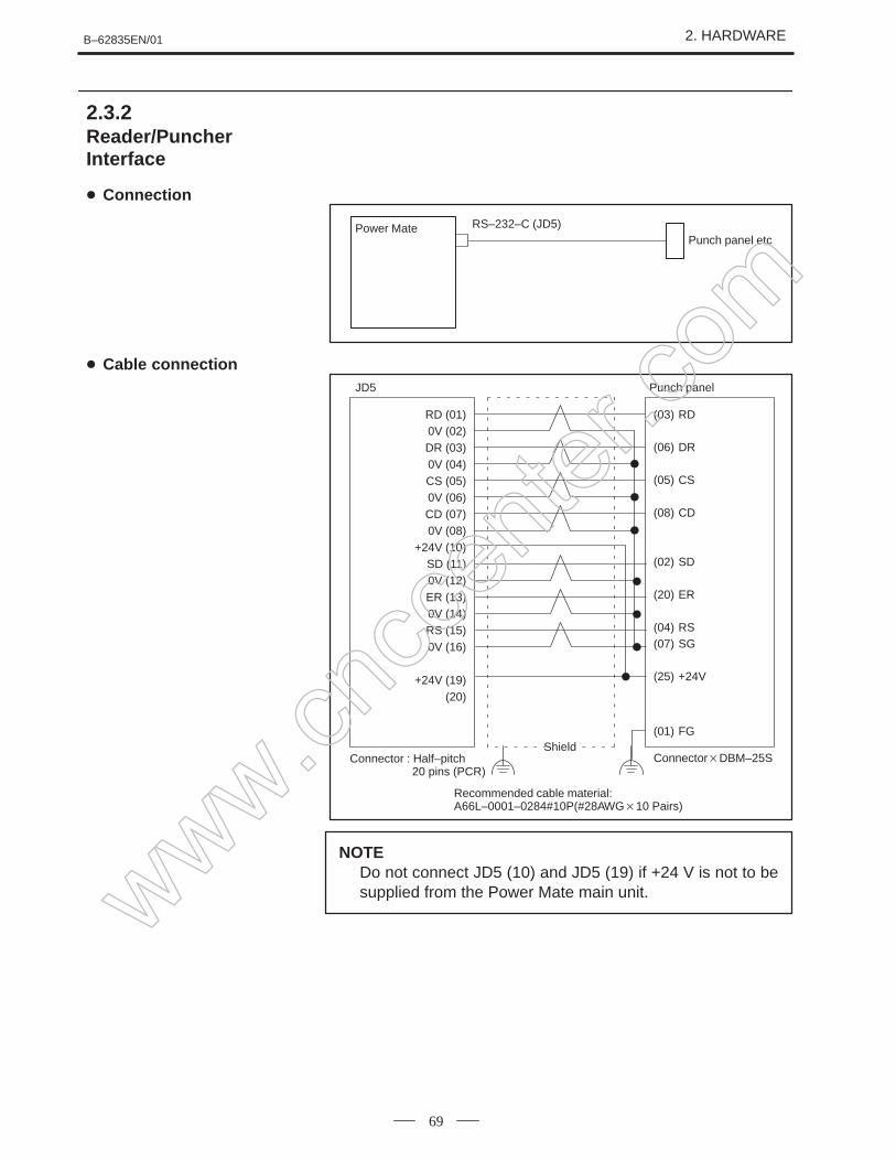
NOTEDo not connect JD5 (10) and JD5 (19) if +24 V is not to besupplied from the Power Mate main unit.
2.3.2Reader/PuncherInterface
Connection
Cable connection
www.cncc
enter
.com
2. HARDWARE B–62835EN/01
70
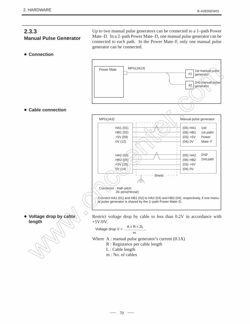
Up to two manual pulse generators can be connected to a 1–path PowerMate–D. In a 2–path Power Mate–D, one manual pulse generator can beconnected to each path. In the Power Mate–F, only one manual pulsegenerator can be connected.
MPG(JA13)1st manual pulsegenerator
Power Mate#1
#22nd manual pulsegenerator
Connector : Half–pitch 20–pins(Hirose)
MPG(JA3) Manual pulse generator
HA1 (01)HB1 (02)+5V (09)0V (12)
HA2 (03)HB2 (04)+5V (18)0V (14)
(05) HA1(06) HB1(03) +5V(04) 0V
(05) HA2(06) HB2(03) +5V(04) 0V
Connect HA1 (01) and HB1 (02) to HA2 (03) and HB2 (04), respectively, if one manu-al pulse generator is shared by the 2–path Power Mate–D.
Shield
1st/1st path/Power Mate–F
2nd/2nd path
Restrict voltage drop by cable to less than 0.2V in accordance with+5V/0V.
Voltage drop V =AR2L
m
Where A : manual pulse generator’s current (0.1A)R : Registance per cable lengthL : Cable lengthm : No. of cables
2.3.3Manual Pulse Gen erator
Connection
Cable connection
Voltage drop by cablelength
www.cncc
enter
.com
B–62835EN/01 2. HARDWARE
71
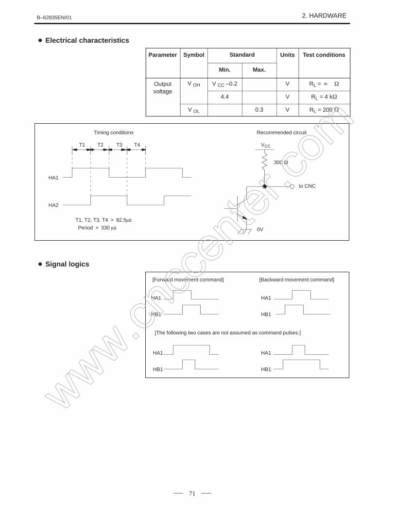
Parameter Symbol Standard Units Test conditions
Min. Max.
Outputvoltage
V OH V CC –0.2 V RL =
voltage4.4 V RL = 4 k
V OL 0.3 V RL = 200
Timing conditions Recommended circuit
T1 T2 T3 T4
HA1
HA2
VCC
to CNC
0V
T1, T2, T3, T4 > 82.5s
Period > 330 s
300
[Forward movement command] [Backward movement command]
HA1
HB1
HA1
HB1
HA1
HB1
HA1
HB1
[The following two cases are not assumed as command pulses.]
Electrical characteristics
Signal logics
www.cncc
enter
.com
2. HARDWARE B–62835EN/01
72
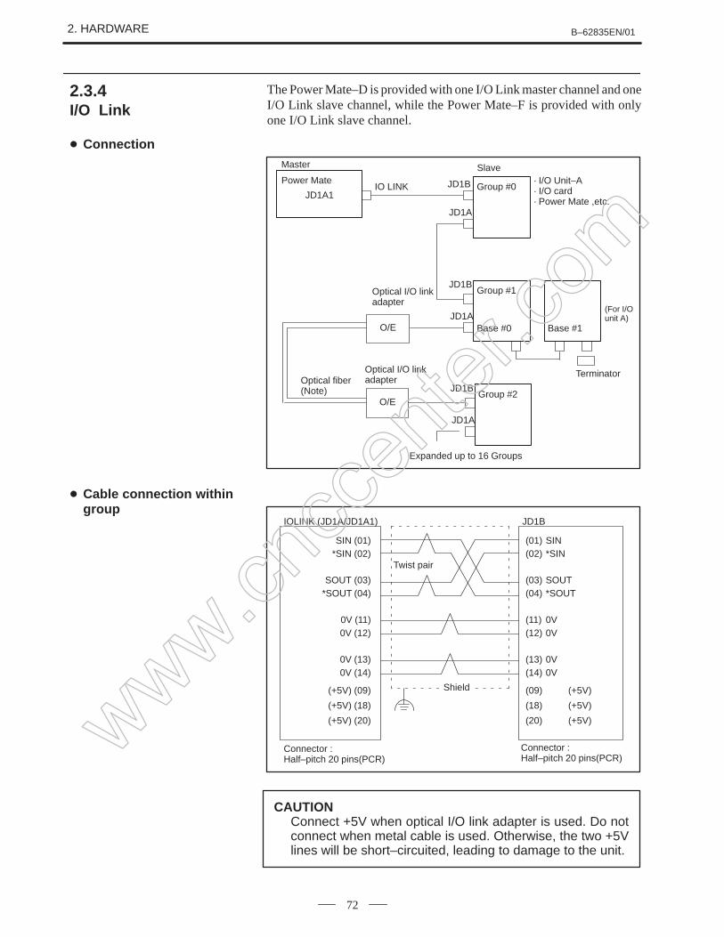
The Power Mate–D is provided with one I/O Link master channel and oneI/O Link slave channel, while the Power Mate–F is provided with onlyone I/O Link slave channel.
Power MateIO LINK JD1B
JD1A
Group #0· I/O Unit–A· I/O card· Power Mate ,etc.
Group #1JD1B
Base #0 Base #1JD1A
O/E
Optical I/O linkadapter
Terminator
O/E
Optical I/O linkadapterOptical fiber
(Note) Group #2JD1B
JD1A
Expanded up to 16 Groups
(For I/Ounit A)
JD1A1
Master Slave
Connector : Half–pitch 20 pins(PCR)
Connector : Half–pitch 20 pins(PCR)
IOLINK (JD1A/JD1A1) JD1B
SIN (01)*SIN (02)
SOUT (03)*SOUT (04)
0V (11)0V (12)
0V (13)0V (14)
(+5V) (09)
(+5V) (18)
(+5V) (20)
(01) SIN(02) *SIN
(03) SOUT(04) *SOUT
(11) 0V(12) 0V
(13) 0V(14) 0V
(09) (+5V)
(18) (+5V)
(20) (+5V)
Shield
Twist pair
CAUTIONConnect +5V when optical I/O link adapter is used. Do notconnect when metal cable is used. Otherwise, the two +5Vlines will be short–circuited, leading to damage to the unit.
2.3.4I/O Link
Connection
Cable connection withingroup
www.cncc
enter
.com
B–62835EN/01 2. HARDWARE
73
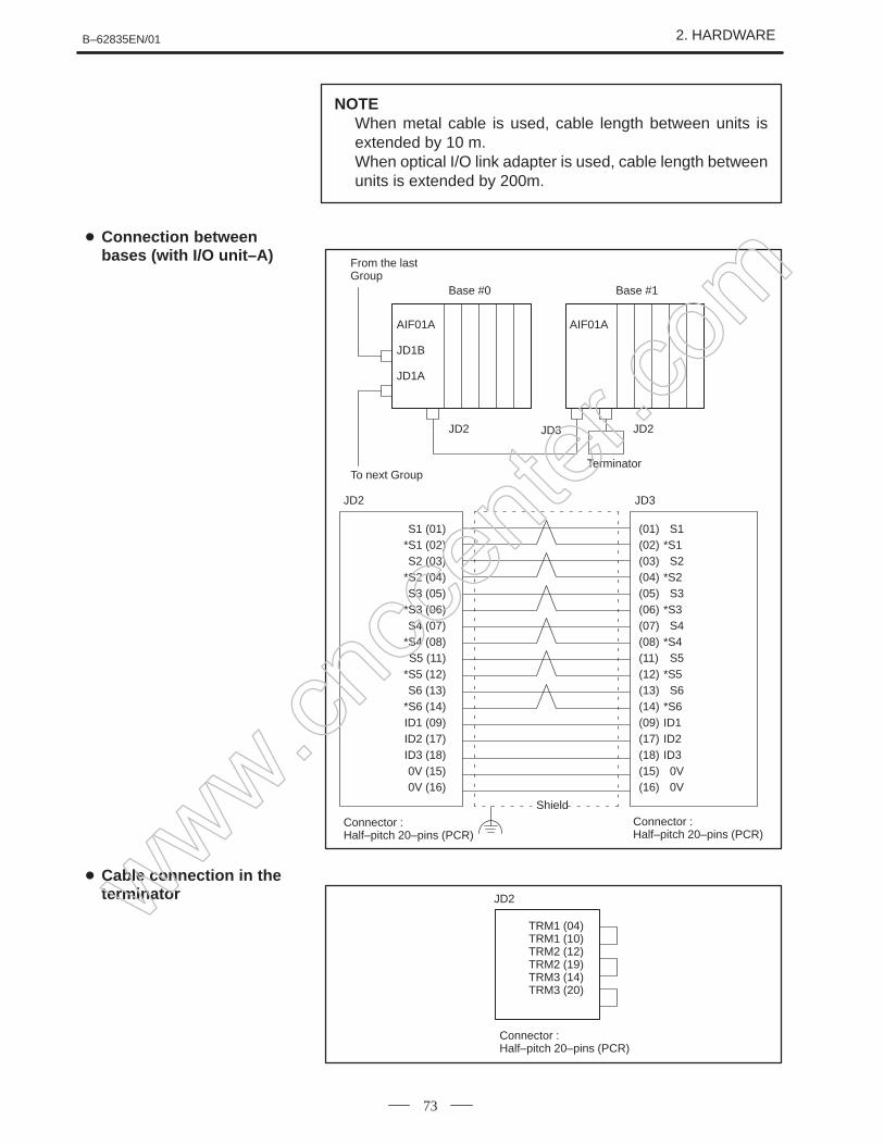
NOTEWhen metal cable is used, cable length between units isextended by 10 m.When optical I/O link adapter is used, cable length betweenunits is extended by 200m.
NOTEIf there is more than I/O unit A in the same group, aterminator is connected to the JP2 connector of the lastAIF01B. No terminator is needed for the JD1A connectorof the last unit on the I/O Link line.
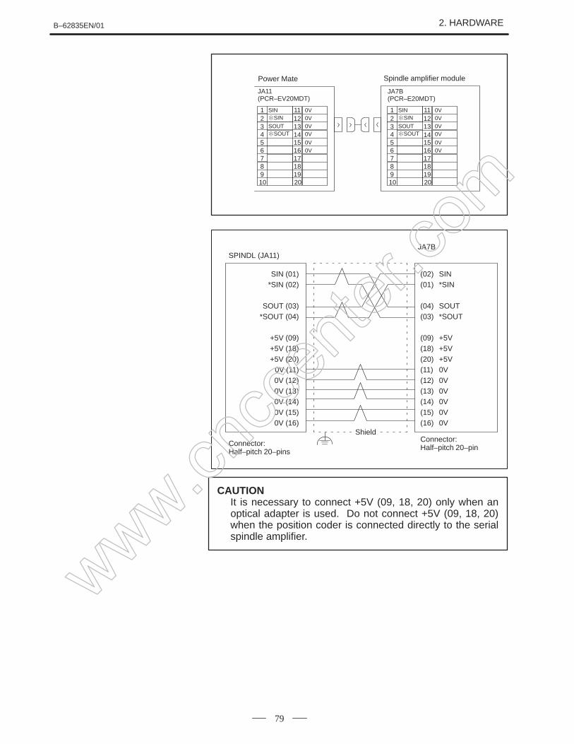
CAUTIONIt is necessary to connect +5V (09, 18, 20) only when anoptical adapter is used. Do not connect +5V (09, 18, 20)when the position coder is connected directly to the serialspindle amplifier.
www.cncc
enter
.com
2. HARDWARE B–62835EN/01
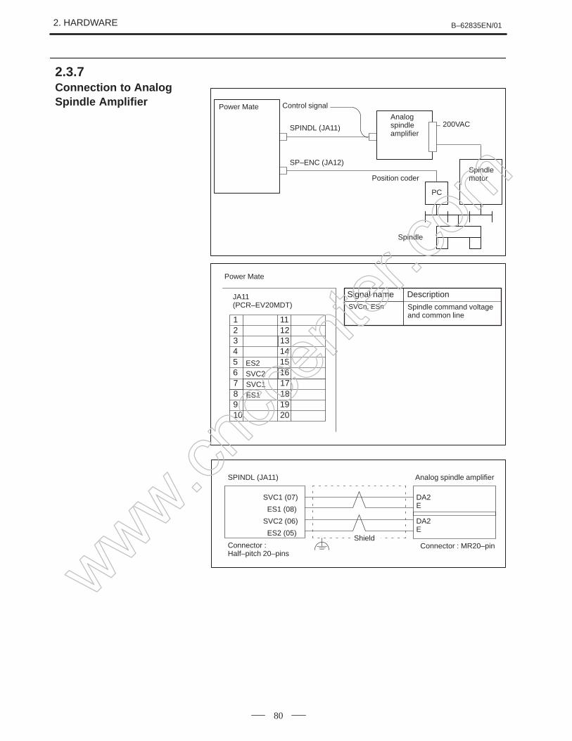
80
SP–ENC (JA12)Spindlemotor
200VACAnalog spindle amplifier
Power Mate Control signal
Position coder
PC
SPINDL (JA11)
Spindle
1
32
ES2
4
65
SVC2SVC1
87
ES1910
11
1312
14
1615
1817
1920
Description
Spindle command voltageand common line
Power Mate
JA11(PCR–EV20MDT)
Signal nameSVCn, ESn
Connector : Half–pitch 20–pins
SPINDL (JA11) Analog spindle amplifier
SVC1 (07)
ES1 (08)
SVC2 (06)
ES2 (05)Shield
Connector : MR20–pin
DA2E
DA2E
2.3.7Connection to Analog Spindle Amplifier
www.cncc
enter
.com
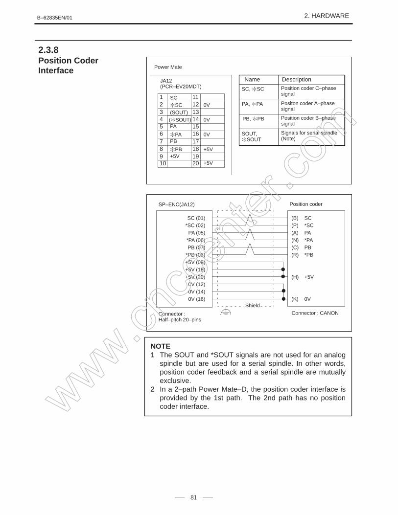
B–62835EN/01 2. HARDWARE
81
SC
1
3
SC2
(SOUT)
PA4
6
(SOUT)5
PAPB
87
PB9 +5V10
0V
11
1312
14
16
0V15
0V
1817
+5V
+5V1920
Description
Positon coder A–phase signal
Signals for serial spindle(Note)
Position coder C–phasesignal
Power Mate
JA12(PCR–EV20MDT)
Name
PA, PA
SOUT,SOUT
SC, SC
Position coder B–phasesignal
PB, PB
Shield
Connector : CANONConnector : Half–pitch 20–pins
SP–ENC(JA12) Position coder
SC (01)*SC (02)
PA (05)*PA (06)PB (07)
*PB (08)+5V (09)+5V (18)+5V (20)
0V (12)0V (14)0V (16)
(B) SC(P) *SC(A) PA(N) *PA(C) PB(R) *PB
(H) +5V
(K) 0V
NOTE1 The SOUT and *SOUT signals are not used for an analog
spindle but are used for a serial spindle. In other words,position coder feedback and a serial spindle are mutuallyexclusive.
2 In a 2–path Power Mate–D, the position coder interface isprovided by the 1st path. The 2nd path has no positioncoder interface.
2.3.8Position CoderInterface
www.cncc
enter
.com
2. HARDWARE B–62835EN/01
82
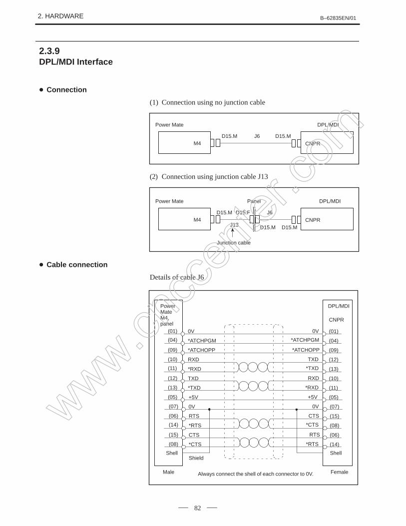
(1) Connection using no junction cable
D15.M
Power Mate
M4 CNPRJ6 D15.M
DPL/MDI
(2) Connection using junction cable J13
D15.M
Power Mate
M4 CNPRJ6
D15.M
DPL/MDI
D15.F
Panel
J13 D15.M
Junction cable
Details of cable J6
(01)
(04)
(09)
(10)
(11)
(12)
(13)
(05)
0V
*ATCHPGM
*ATCHOPP
RXD
*RXD
TXD
*TXD
+5V
0V
*ATCHPGM
*ATCHOPP
TXD
*TXD
RXD
*RXD
+5V
(01)
(04)
(09)
(12)
(13)
(10)
(11)
(05)
(07)
(06)
(14)
(15)
(08)
0V
RTS
*RTS
CTS
*CTS
0V
CTS
*CTS
RTS
*RTS
(07)
(15)
(08)
(06)
(14)
CNPR
Shield
Power MateM4,panel
DPL/MDI
Shell Shell
Male FemaleAlways connect the shell of each connector to 0V.
2.3.9DPL/MDI Interface
Connection
Cable connection
www.cncc
enter
.com
B–62835EN/01 2. HARDWARE
83
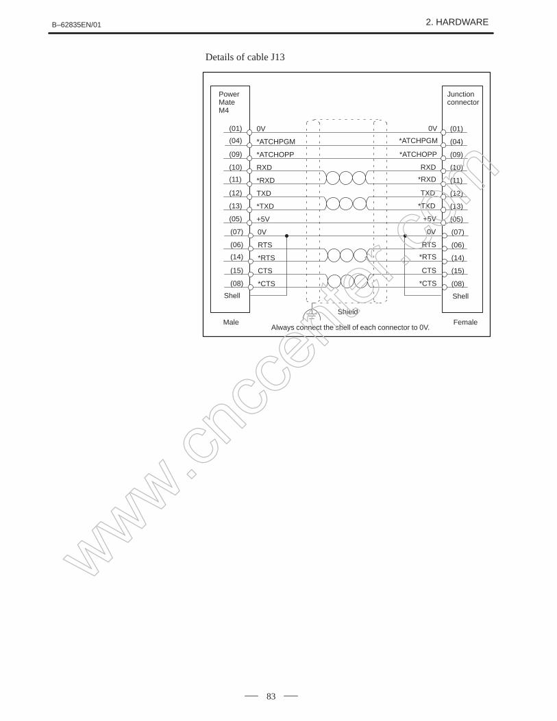
Details of cable J13
(01)
(04)
(09)
(10)
(11)
(12)
(13)
(05)
0V
*ATCHPGM
*ATCHOPP
RXD
*RXD
TXD
*TXD
+5V
0V
*ATCHPGM
*ATCHOPP
RXD
*RXD
TXD
*TXD
+5V
(01)
(04)
(09)
(10)
(11)
(12)
(13)
(05)
(07)
(06)
(14)
(15)
(08)
0V
RTS
*RTS
CTS
*CTS
0V
RTS
*RTS
CTS
*CTS
(07)
(06)
(14)
(15)
(08)
Power MateM4
Junction connector
Shell
Shield
Shell
Male FemaleAlways connect the shell of each connector to 0V.
www.cncc
enter
.com
2. HARDWARE B–62835EN/01
84
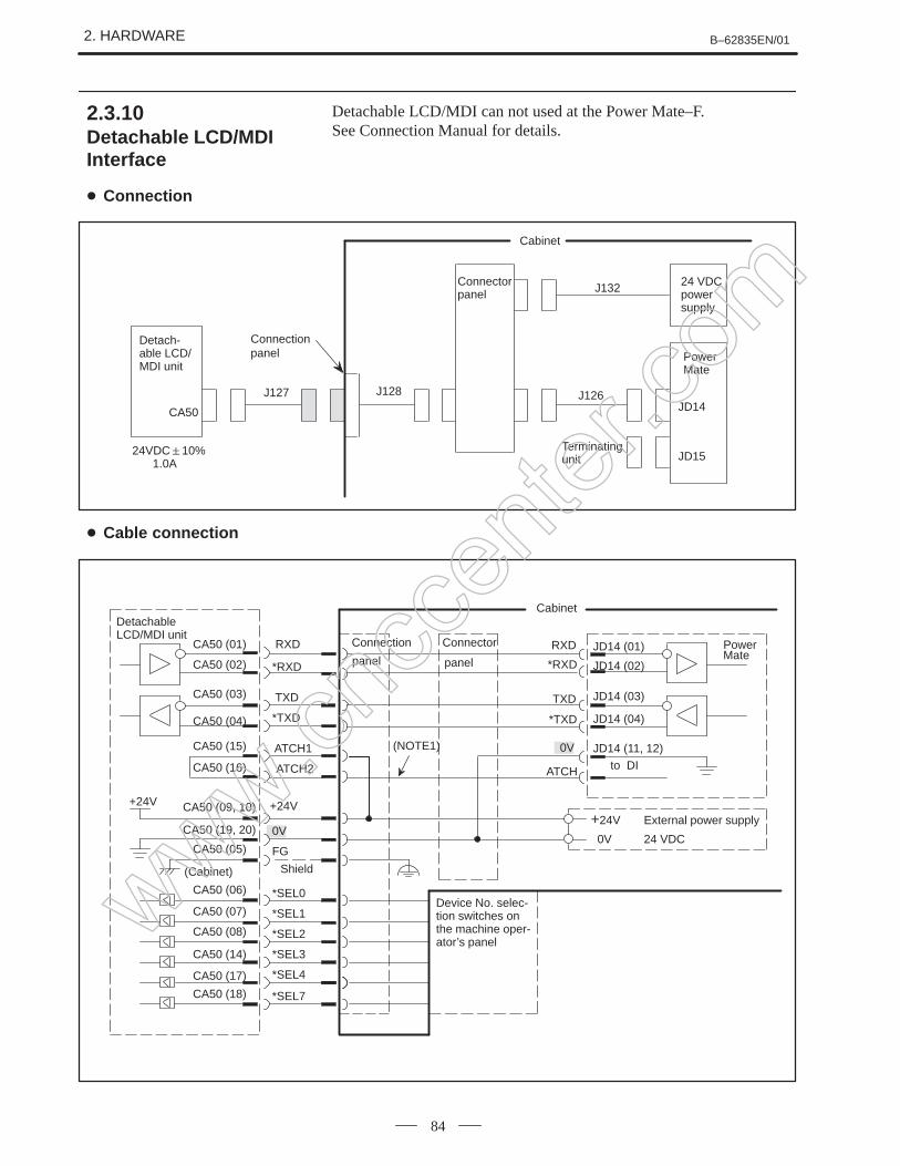
Detachable LCD/MDI can not used at the Power Mate–F.See Connection Manual for details.
Handy operator’s panel can not used at the Power Mate–F.
NOTE1 If 24 V is not applied to emergency stop input EMGTP
(CRS10–11) of the handy operator’s panel, the handyoperator’s panel enters the emergency stop state.
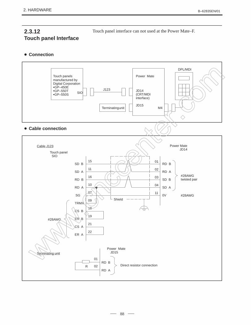
2 The terminating unit connected to the JD15 connector of thePower Mate is not a CRT link terminating unit. This is thesame as the touch panel terminating unit (2.3.12).
3 Set rotary switch MTSW of the Power Mate main unit to 3.
2.3.11Handy Operator’sPanel Interface
www.cncc
enter
.com
2. HARDWARE B–62835EN/01
86
Connectorpanel
PowerMate
JD14
JD15
Handyoperator’spanel
Connectionpanel
Terminatingunit
24 VDCpowersupply
Emergencystop on ma-chine opera-tor’s panel,etc.
24VDC10%0.2A
J121
Safetyrelay
Cabinet
J118 J122 J120
J135
J119
CRS10
Handy operator’spanel enableswitch
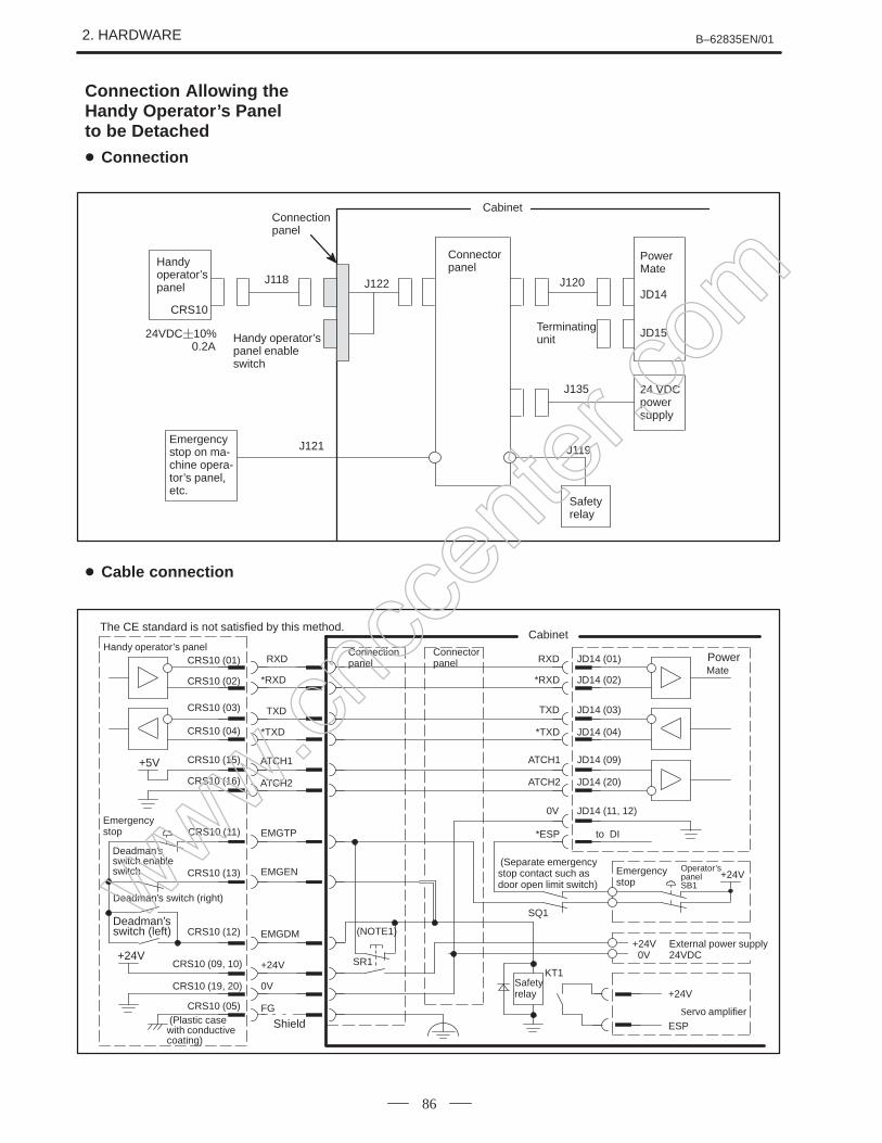
The CE standard is not satisfied by this method.
Handy operator’s panelCRS10 (01)
Deadman’sswitch (left)
Deadman’s switch (right)
(Plastic casewith conductivecoating)
Emergencystop
RXD
CRS10 (02)
CRS10 (15)
CRS10 (03)
*RXD
CRS10 (04)
CRS10 (16)
+5V
CRS10 (11)
TXD
*TXD
ATCH1
ATCH2
Shield
EMGTP
CRS10 (13)
Deadman’sswitch enableswitch
CRS10 (12)
CRS10 (09, 10)
CRS10 (19, 20)
CRS10 (05)
EMGEN
EMGDM
+24V
0V
FG
Connectorpanel
Connectionpanel
Cabinet
(Separate emergencystop contact such asdoor open limit switch)
+24V
Safetyrelay
Operator’s panelSB1
Emergencystop
(NOTE1)+24V External power supply 0V 24VDC
Servo amplifier
RXD
*RXD
TXD
*TXD
ATCH1
ATCH2
0V
*ESP
Power Mate
JD14 (01)
JD14 (02)
JD14 (03)
JD14 (04)
JD14 (09)
JD14 (20)
JD14 (11, 12)
to DI
+24V
SQ1
SR1KT1
+24V
ESP
Connection Allowing theHandy Operator’s Panelto be Detached
Connection
Cable connection
www.cncc
enter
.com
B–62835EN/01 2. HARDWARE
87
Connectorpanel
PowerMate
JD14
JD1524VDC 10%0. 2A
CRS10
Terminatingunit
24 VDCpowersupply
Emergency stopon machine op-erator’s panel,etc.
J121
Safetyrelay
Cabinet
J118 J120
J135
J119
Handyoperator’spanel
Deadman’sswitch (right)
Emergen-cy stop
Handy operator’s panelCRS10 (01)
Deadman’sswitch (left)
(Plastic case withconductive coating)
Emergencystop
RXD
CRS10 (02)
CRS10 (15)
CRS10 (03)
*RXD
CRS10 (04)
CRS10 (16)
+5V
CRS10 (11)
TXD
*TXD
ATCH1
ATCH2
Shield
EMGTP
CRS10 (13)
Deadman’sswitch en-able switch
CRS10 (12)
CRS10 (09, 10)
CRS10 (19, 20)
CRS10 (05)
EMGEN
EMGDM
+24V
0V
FG
Connector panel
(Separate emergencystop contact such as thedoor open limit switch)
+24V
Safetyrelay
Operator’s panel SB1
Servo amplifier
RXD
*RXD
TXD
*TXD
ATCH1
ATCH2
0V
*ESP
Power Mate
JD14 (01)
JD14 (02)
JD14 (03)
JD14 (04)
JD14 (09)
JD14 (20)
JD14 (11, 12)
to DI
+24V
SQ1
KT1
+24V
ESP
0V 24VDC
+24V External power supply
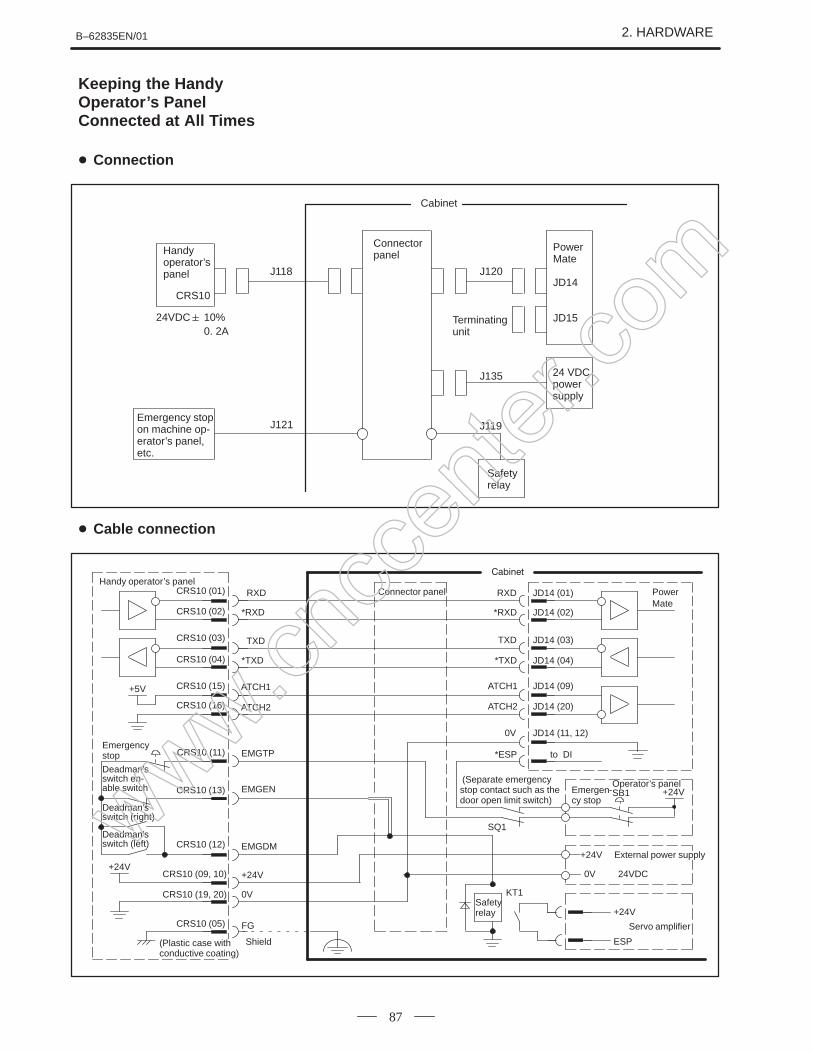
Keeping the HandyOperator’s PanelConnected at All Times
Connection
Cable connection
www.cncc
enter
.com
2. HARDWARE B–62835EN/01
88
Touch panel interface can not used at the Power Mate–F.
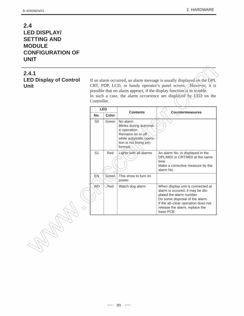
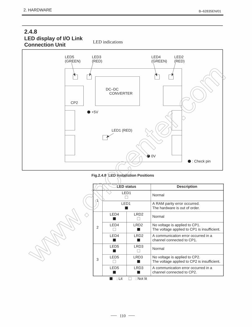
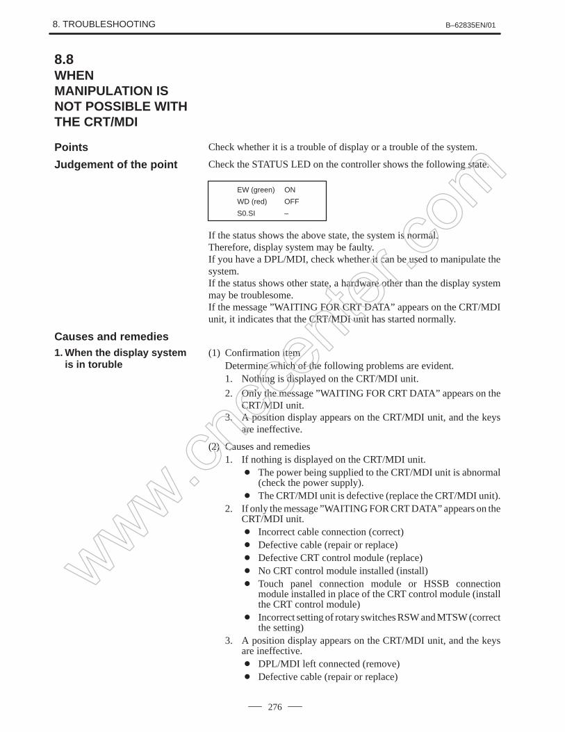
If an alarm occurred, an alarm message is usually displayed on the DPLCRT, PDP, LCD, or handy operator’s panel screen. However, it ispossible that no alarm appears, if the display function is in trouble.In such a case, the alarm occurrence are displayed by LED on theController.
LEDContents Co ntermeas res
No. ColorContents Countermeas ures
S0 Green No alarmBlinks during automat-ic operation.Remains on or offwhile automatic opera-tion is not being per-formed.
S1 Red Lights with all alarms An alarm No. is displayed in theDPL/MDI or CRT/MDI at the sametime.Make a corrective measure by thealarm No.
EN Green This show to turn onpower.
WD Red Watch dog alarm When display unit is connected atalarm is occured, it may be dis-plaied the alarm number.Do some disposal of the alarm.If the all–clear operation does notrelease the alarm, replace thebase PCB
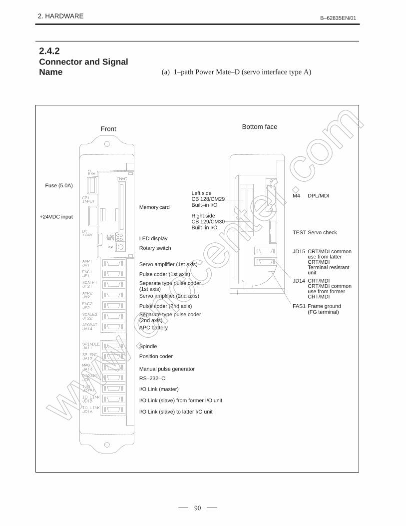
Separate type pulse coder(1st axis)Servo amplifier (2nd axis)
Pulse coder (2nd axis)
Separate type pulse coder(2nd axis)APC battery
Spindle
Position coder
Manual pulse generator
RS–232–C
I/O Link (master)
I/O Link (slave) from former I/O unit
I/O Link (slave) to latter I/O unit
Bottom face
Left sideCB 128/CM29Built–in I/O
Right sideCB 129/CM30Built–in I/O
JD15 CRT/MDI common use from latter CRT/MDI
Terminal resistant unit
TEST Servo check
FAS1 Frame ground (FG terminal)
JD14 CRT/MDICRT/MDI common use from former CRT/MDI
M4 DPL/MDI
2.4.2Connector and SignalName
www.cncc
enter
.com
B–62835EN/01 2. HARDWARE
91
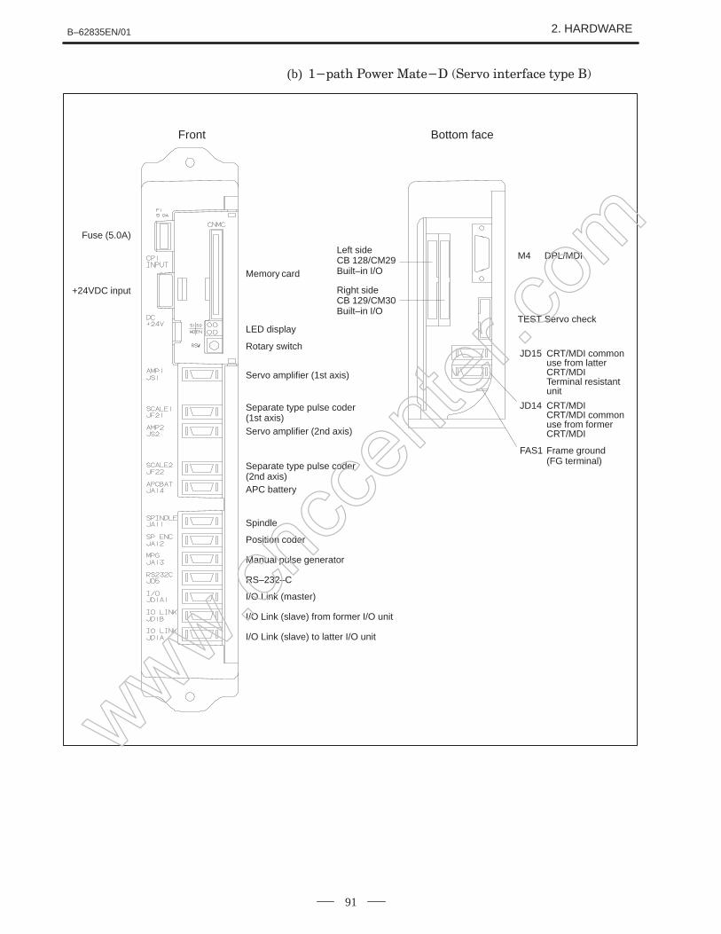
(b)
Front
Fuse (5.0A)
+24VDC input
Memory card
LED display
Rotary switch
Servo amplifier (1st axis)
Separate type pulse coder(1st axis)
Separate type pulse coder(2nd axis)APC battery
Spindle
Position coder
Manual pulse generator
RS–232–C
I/O Link (master)
I/O Link (slave) from former I/O unit
I/O Link (slave) to latter I/O unit
Bottom face
Left sideCB 128/CM29Built–in I/O
Right sideCB 129/CM30Built–in I/O
M4 DPL/MDI
TEST Servo check
JD15 CRT/MDI common use from latter CRT/MDI
Terminal resistant unit
FAS1 Frame ground (FG terminal)
JD14 CRT/MDICRT/MDI common use from former CRT/MDIServo amplifier (2nd axis)
www.cncc
enter
.com
2. HARDWARE B–62835EN/01
92
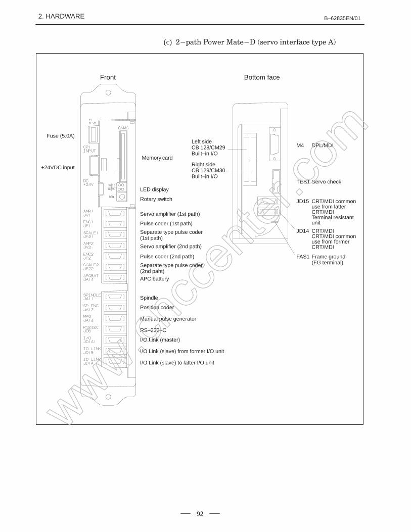
(c)
Front
Fuse (5.0A)
+24VDC input
Memory card
LED display
Rotary switch
Servo amplifier (1st path)
Pulse coder (1st path)
Separate type pulse coder (1st path)
Pulse coder (2nd path)
Separate type pulse coder (2nd paht)
Servo amplifier (2nd path)
APC battery
Spindle
Position coder
Manual pulse generator
RS–232–C
I/O Link (master)
I/O Link (slave) from former I/O unit
I/O Link (slave) to latter I/O unit
Bottom face
Left sideCB 128/CM29Built–in I/O
Right sideCB 129/CM30Built–in I/O
TEST Servo check
JD15 CRT/MDI common use from latter CRT/MDI
Terminal resistant unit
FAS1 Frame ground (FG terminal)
JD14 CRT/MDICRT/MDI common use from former CRT/MDI
M4 DPL/MDI
www.cncc
enter
.com
B–62835EN/01 2. HARDWARE
93
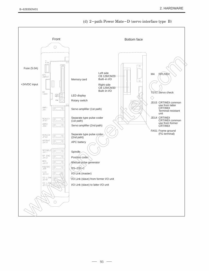
(d)
Front
Fuse (5.0A)
+24VDC input
Memory card
LED display
Rotary switch
Servo amplifier (1st path)
Separate type pulse coder (2nd paht)
APC battery
Spindle
Manual pulse generator
RS–232–C
I/O Link (slave) from former I/O unit
I/O Link (slave) to latter I/O unit
Bottom face
Left sideCB 128/CM29Built–in I/O
Right sideCB 129/CM30Built–in I/O
M4 DPL/MDI
TEST Servo check
JD15 CRT/MDI common use from latter CRT/MDI
Terminal resistant unit
FAS1 Frame ground (FG terminal)
JD14 CRT/MDICRT/MDI common use from former CRT/MDI
Separate type pulse coder (1st path)
Servo amplifier (2nd path)
Position coder
I/O Link (master)
www.cncc
enter
.com
2. HARDWARE B–62835EN/01
94
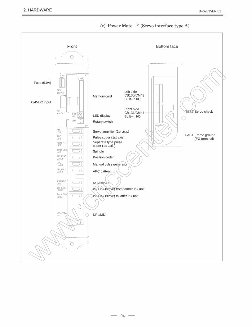
(e)
Fuse (5.0A)
+24VDC input
Memory card
LED display
Rotary switch
Servo amplifier (1st axis)
Pulse coder (1st axis)Separate type pulse coder (1st axis)
Spindle
Position coder
Manual pulse generator
RS–232–C
APC battery
I/O Link (slave) from former I/O unit
I/O Link (slave) to latter I/O unit
DPL/MDI
Front
Left sideCB130/CM43Built–in I/O
Right sideCB131/CM44Built–in I/O
TEST Servo check
FAS1 Frame ground (FG terminal)
Bottom face
www.cncc
enter
.com
B–62835EN/01 2. HARDWARE
95
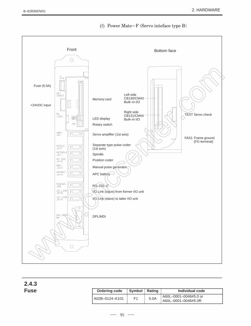
(f)
Fuse (5.0A)
+24VDC input
Memory card
LED display
Rotary switch
Front
Servo amplifier (1st axis)
Separate type pulse coder (1st axis)
Spindle
Position coder
Manual pulse generator
APC battery
RS–232–C
I/O Link (slave) from former I/O unit
I/O Link (slave) to latter I/O unit
DPL/MDI
Bottom face
Left sideCB130/CM43Built–in I/O
Right sideCB131/CM44Built–in I/O
TEST Servo check
FAS1 Frame ground (FG terminal)
Ordering code Symbol Rating Individual code
A02B–0124–K101 F1 5.0AA60L–0001–0046#5.0 or A60L–0001–0046#5.0R
2.4.3Fuse
www.cncc
enter
.com
2. HARDWARE B–62835EN/01
96
Lithium battery code : A20B–0118–K111
When CRT/MDI common functions and RSW simaltaneous block startat the power Mate–D are used, set device numbers from 0 to 15 with therotary switch (RSW). Assign the number from the first Power Mate–D inorder.
Device No. RSW setting
0 0
1 1
2 2
3 3
When CRT/MDI common functions and RSW simaltaneous block startare not used, set device number to 0.
Setting of rotary switch RSW
NOTEThe Power Mate–F is not provided with rotary switch RSW.
2.4.4Battery of Controller
2.4.5Setting the RotarySwitch RSW
www.cncc
enter
.com
B–62835EN/01 2. HARDWARE
97
Set MTSW to 0 for general use.When handy operator’s panel is used, set MTSW to 3.Normally, do not set other number except [0] and [3].
2.4.6Rotary Switch MTSW
www.cncc
enter
.com
2. HARDWARE B–62835EN/01
98
a) Power Mate–D (A02B–0166–B001)
AMP1 JV1 Servo amplifier (1st axis)
ENC1 JF1 Pulse coder (1st axis)
SCALE1 JF21 Separate type pulse coder (1st axis)
AMP2 JV2 Servo amplifier (2nd axis)
ENC2 JF2 Pulse coder (2nd axis)
SCALE2 JF22 Separate type pulse coder (2nd axis)
APCBAT JA14 APC battery
NAME NUMBER USE
Memory card CNMC Memory card
S1
LED WD
S0
EN LED display
SVCHK TEST Servo check board
PM/TMNL JD15 CRT Link to latter
CRT/PM JD14 CRT Link from previous step
Rotary switch RSW CRT common function
SPNDLE JA11 Spindle
SP.ENC JA12 Position coder
MPG JA13 Manual pulse generator
RS232C JD5 RS-232-C
I/O JD1A1 I/O Link (master)
I/O Link JD1B I/O Link (slave)from previous step
I/O Link JD1A I/O Link (slave) to latter
DPL/MDI M4 DPL/MDI
(8)
(5) (7)
(2) (4)
(1) (3)
(6)
(9)
F01
(10)
F81
(10)
2.4.7Location of Modulesand Internal PrintedBoards
www.cncc
enter
.com
B–62835EN/01 2. HARDWARE
99
No. NAME Specification Function Display of system con-figuration screen
Base PCB A16B–2201–0630 –
(1) PMC controled module A A20B–2900–0142 PMC–PA1 PMC BIT
PMC controled module B A20B–2901–0660, 0662 PMC–PA3 PMC PMP+SLC
(2) Memory module A A20B–2900–0531 RAM 128KB RAM 128KB
A20B–2902–0332
Memory module B A20B–2900–0530 RAM 256KB RAM 256KB
A20B–2902–0331
Memory module C A20B–2900–0541 RAM 512KB RAM 512KB
Name D F Specifications RemarksCRT/MDI unit A02B–0166–C001 English key
A02B–0166–C003 English key, In–line connection type
A02B–0166–C201#R English key
A02B–0166–C203#R English key, In–line connection type
A02B–0166–C201#S Symbol key
A02B–0166–C203#S Symbol key, In–line connection type
Separate type MDI unit A02B–0166–C010 English key
A02B–0166–C210#R English key
A02B–0166–C213#R English key, In–line connection type
A02B–0166–C210#S Symbol key
A02B–0166–C213#S Symbol key, In–line connection type
Picture display CRT/MDI unit ∆ A02B–0166–C221#R English key For 32 screen
∆ A02B–0166–C221#S Symbol key For 32 screen
∆ A02B–0166–C222#R English key For 64 screen
∆ A02B–0166–C222#S Symbol key For 64 screen
Picture display separate type MDIit
∆ A02B–0166–C231#R English key For 32 screenunit ∆ A02B–0166–C231#S Symbol key For 32 screen
∆ A02B–0166–C232#R English key For 64 screen
∆ A02B–0166–C232#S Symbol key For 64 screen
Separate type CRT unit A02B–0120–C111
Separate type PDP unit A02B–0120–C113 200V AC input
A02B–0200–C100 24V DC input
Separate type LCD unit A02B–0166–C251
Detachable LCD/MDI unit A02B–0166–C271#R English key
A02B–0166–C271#S Symbol key
DPL/MDI unit A02B–0168–K010 Table mount/FANUC English key
A02B–0168–K011 Wall mount/FANUC English key
A02B–0168–K012 Table mount/GE Fanuc English key
A02B–0168–K013 Wall mount/GE Fanuc English key
Long distance type DPL/MDI unit A02B–0118–C030 Table mount/FANUC English key
A02B–0118–C031 Wall mount/FANUC English key
A02B–0118–C032 Table mount/GE Fanuc English key
A02B–0118–C033 Wall mount/GE Fanuc English key
Dust protected type DPL/MDI unit A02B–0118–C130#RTable mount/FANUC
English key
A02B–0118–C130#STable mount/FANUC
Symbol key
A02B–0118–C131#RWall mount/FANUC
English key
A02B–0118–C131#SWall mount/FANUC
Symbol key
A02B–0118–C132#RTable mount/GE Fanuc
English key
A02B–0118–C132#STable mount/GE Fanuc
Symbol key
A02B–0118–C133#RWall mount/GE Fanuc
English key
A02B–0118–C133#SWall mount/GE Fanuc
Symbol key
Position display unit A02B–0118–C020
DPL/MDI switch circuit A16B–2600–0080
CRT link terminal unit A02B–0124–D001 For CRT, PDP, LCD
CRT link intermediate unit A02B–0124–D002
2.5.4CRT/MDI, DPL/MDI Unit
www.cncc
enter
.com
B–62835EN/01 2. HARDWARE
115
Name RemarksSpecificationsFD
Handy operator’s panel ∆ A02B–0211–C020#R English key
∆ A02B–0211–C020#S Symbol key
Touch panel end terminal unit ∆ A02B–0166–D003 For touch panel and handy operator’s panel
HSSB adaptor ∆ A02B–0211–C220
I/O link–II terminal board A08B–0048–C331
NOTE∆ indicates a unit that can be used with theA02B–0166–B501, –B502, and –B531 in the PowerMate–D.
Name D F Specifications RemarksCRT Control printed board A20B–2000–0840
A20B–2000–0841 In–line connection type
∆ A20B–2100–0061 For picture display 32 screen
∆ A20B–2100–0060 For picture display 64 screen
DPL/MDI printed board A20B–8000–0141
Long distance type DPL/MDI for printed board
A20B–8000–0490
Dust protected DPL/MDI P.C.B A20B–8001–0310
DPL/MDI switch board A16B–2600–0080
Handy operator’s panel ∆ A20B–2002–0200
HSSB adaptor ∆ A20B–8001–0510
Position display unit A20B–1004–0360
A20B–1004–0370
NOTE∆ indicates a printed–circuit board that can be used with theA02B–0166–B501, –B502, and –B531 in the PowerMate–D.
2.5.5CRT/MDI, DPL/MDIPrinted Board
www.cncc
enter
.com
2. HARDWARE B–62835EN/01
116
WARNING1 Memory backup battery replacement
When replacing the memory backup batteries, keep thepower to the machine (CNC) switched on, and hold themachine at an emergency stop. Because this work must becarried out while the power is kept switched on and thecabinet is open, only the personnel who have been trainedfor safety are allowed to engage in the work. Whenreplacing the batteries, be careful not to touch thehigh–voltage circuit section (marked and shielded witha shock hazard prevention cover). If you touch thehigh–voltage circuit section when it is uncovered, you willget an electric shock.
2 Absolute pulse coder battery replacementWhen replacing the memory backup batteries, keep thepower to the machine (CNC) switched on, and hold themachine at an emergency stop. Because this work must becarried out while the power is kept switched on and thecabinet is open, only the personnel who have been trainedfor safety are allowed to engage in the work. Whenreplacing the batteries, be careful not to touch thehigh–voltage circuit section (marked and shielded witha shock hazard prevention cover). If you touch thehigh–voltage circuit section when it is uncovered, you willget an electric shock.
2.6HOW TO REPLACETHE BATTERIES
www.cncc
enter
.com
B–62835EN/01 2. HARDWARE
117
Procedure for replacing the battery for memory back up.
1 Lithium battery (Order number is *A02B–0118–K111) is required.
2 Replace battery in the status that Power Mate power supply is ON.
3 The battery used for memory back up is located in the front door.
4 Open the door of controller and remove the battery from folder.
5 Pinch and remove the connector in the side of battery towards you.
6 Connect the connector of new battery to the connector.
7 Mount a battery to folder and close the cover in side of cable.
CAUTIONEnsure that the power to the CNC is turned on beforeattempting to replace the battery. Replacing the batterywhile the power is turned off will result in the loss of storeddata such as programs and parameters.
BATTERY
Connector on the cable
Battery
Connector on theprinted circuitboard
Control unit
ÂÂ
Battery
Control unit front panel
Battry (ordering infomation : A02B–0118 K111)
2.6.1
www.cncc
enter
.com
2. HARDWARE B–62835EN/01
118
Prepare lithium battery A06B–6073–K001(*) in advance.
(*) FANUC specification: A98L–0001–0902
Procedure for replacing batteries for absolute pulse coder
1 Turn machine (NC) power ON.
2 Remove the battery case on the front panel of α series Servo AmpModule (SVM).The battery case can be removed by holding the top of the case andpulling the case towards you.
α seriesSVM
Battery caseConnector CX5X Connector
CX5X
Batterycompartment
BatteryA06B–6073–K001
3 Remove the connector the battery.
4 Replace the battery, and connect the connector.
5 Attach the battery case.
6 Turn machine (NC) power OFF.
CAUTION1 Replace the batteries for absolute pulse coder when NC
power is ON.Replacing the batteries with power OFF causes theabsolute position stored in memory to be lost.
2 If your machine is equipped with a separate battery case,follow the instructions in 2.6.4
2.6.2Replacing Batteries forAbsolute Pulse Coder(α Series ServoAmplifier/Built–in TypeBattery)
Procedure
www.cncc
enter
.com
B–62835EN/01 2. HARDWARE
119
Prepare lithium battery A02B–0168–K111(*) in advance.
(*) FANUC specification: A98L–0031–0011
Procedure for replacing batteries for absolute pulse coder
1 Turn machine (NC) power ON.
2 Remove the battery case from under the β series servo amplifiermodule by holding the case at both sides and pulling downwards.
CAUTION1 Replace the batteries for absolute pulse coder when NC
power is ON.Replacing the batteries with power OFF causes theabsolute position stored in memory to be lost.
2 If your machine is equipped with a separate battery case,follow the instructions in 2.6.4
2.6.3Replacing Batteries forAbsolute Pulse Coder(β Series Servo AmpModule/Built–in TypeBattery)
Procedure
www.cncc
enter
.com
2. HARDWARE B–62835EN/01
120
Prepare 4 alkaline batteries (UM–1type) commercially available inadvance.
Procedure for replacing batteries for absolute pulse coder
1 Turn machine (NC) power ON.
2 Loosen screws on the battery case to remove the cover. For placementof the battery case, refer to the machine tool builder’s manual.
3 Replace the batteries in the case. Insert 2 batteries each in the oppositedirection as illustrated below.
ÇÇ
ÇÇ
Screw
Cover
4 After replacement, install the cover.
5 Turn machine (NC) power OFF
CAUTIONReplace the batteries for absolute pulse coder when NCpower is ON.Replacing the batteries with power OFF causes theabsolute position stored in memory to be lost.
2.6.4Replacing Batteries forAbsolute Battery
Procedure
www.cncc
enter
.com
B–62835EN/01 2. HARDWARE
121
1 Check that the power supply is not off.2 Pull the latches of the module socket outwards. (Fig.(a))3 Pull out the module upward. (Fig.(b))
1 Check that the power supply is off.2 Insert the new module board diagonally with B–SIDE outward
(Fig.(b))3 While pushing on the upper edge of the module board, raise it until
it is locked (Fig.(c)).
(a)
No.1 pin
(b)
(c)
CAUTION1 Replacing the memory module results in the loss of stored
data such as programs, parameters, and ladder. Beforeattempting to replace the memory module, therefore, makea backup copy of the stored data.
2 Make sure that the latches at both ends of the socket arecorrectly engaged with the module. If either latch is notengaged securely, it will not be possible to establish asatisfactory electrical contact, possibly leading to amalfunction of the NC unit.
2.7HOW TO REPLACETHE MODULES
2.7.1Removing
2.7.2Insertion
www.cncc
enter
.com
2. HARDWARE B–62835EN/01
122
1 Make sure that the power supply unit is turned off.
2 Disconnect all cables connected to the printed circuit board in thecontrol unit. Pinch the 20–pin half–pitch connector to release thelatch. Draw out the connector.
3 Remove the control unit from the wall.
4 Place the control unit with its left face upward, and press the twopoints shown in Fig. 2.8.1 (a) to remove the cover of the case.
5 Remove the battery.
6 Release the three latches shown in Fig. 2.8.1 (b), and remove the PCboard.
7 Mount a new base PC board by following the steps above in reverseorder.
8 Reconnect the cables to their original positions.
CAUTIONReplacing the base printed circuit board results in the lossof stored data such as programs and parameters. Beforeattempting to replace the memory module, therefore, makea backup copy of the stored data.
2.8REPLACINGPRINTED CIRCUITBOARD AND UNIT
2.8.1The Base PrintedCircuit Boards
www.cncc
enter
.com
B–62835EN/01 2. HARDWARE
123
(Left side view) (Left side view)
Fig. 2.8.1 (a)
Base printed circuit
board
Fig. 2.8.1 (b)
How to remove the plastic cover at the left side of the case
Pull the cover in the direction of arrows as shownbelow while holding down two portions marked withPUSH.
When mounting the cover, insert the cover in thedirection opposite to that of the arrows while holdingdown the two portions marked with PUSH.
How to remove the base printed circuit board
Remove the 3 V dry cell for backing up the RAMbattery.
There are three claws which hold the base printedcircuit board. While moving one at a time to the left (inthe direction of arrows shown below) in the order of(1), (2), and (3), pull the left side of the board to releasethe hold. When releasing the claws, be careful not tobend the pins of components on modules adjacent tothe base printed–circuit board.
Move the board to the left to remove it from the case.
Power supply printedcircuit board
F1
CP1
(1)
(2)
(3)
1 Make sure that the power supply unit is turned off.
2 As in 2.8.1 above, remove the base PC board.
3 Remove the screws from the base PC board or sub printed board thatare securing the power PC board, and replace the power PC board.
4 Put the base PC board in the case, and return it to the original position.
5 Reconnect the cables to their original positions.
2.8.2The Power SupplyPrinted Circuit Boardsand Sub Printed Boardwww.cn
ccen
ter.co
m
2. HARDWARE B–62835EN/01
124
1 Remove the power PC board as in 2.8.2 above.
2 Remove the two screws from the fan motor on the power PC board,and replace the fan motor with a new one.
3 Mount the power PC board on the base PC board as in 2.8.2 above,and return the base PC board to the case.
4 Reconnect the cables.
1 Turn off the power to the CRT/MDI, separated type CRT/MDI unitand controller.
2 The CRT control PCB is located behind the MDI. Remove all cables connected to the PCB.
3 Remove the square screws from the CRT control board, and replacethe PCB.
4 Reconnect the cables.
CAUTIONWhen the picture display CRT/MDI unit or separate picturedisplay MDI unit is being used, reload the picture screendata.
2.8.3The Fan motor
2.8.4The CRT ControlPrinted Circuit Board
www.cncc
enter
.com
B–62835EN/01 2. HARDWARE
125
1 The CRT control board that is behind the MDI keyboard can be seenfrom the rear of the CRT/MDI unit and separate type MDI unit.Remove the CRT control board as in 2.8.4 above.
2 Remove the two connectors from the back of the keyboard.
3 Remove the four studs from the back of the keyboard.
4 Since the MDI keyboard has no setscrews, the keyboard can beremoved at this point.
5 Mount a new keyboard, and secure it with four studs.
6 Reconnect the two cables of the CRT control board.
CRT/MDI control boardStudMDI keyboard
Screw
1 Check that the power supply is off.
2 Disconnect the CRT unit power cable and the video signal cable.
3 Remove the chloridized veneer cover and the four screws from thefront of the CRT unit.
4 Install the new CRT unit.
5 Reconnect the CRT power supply cable and video signal cable to theiroriginal positions.
9” monochrome CRT
Fig.2.8.6 Replacing the CRT Display
2.8.5The MDI Keyboard
2.8.6The CRT Display
www.cncc
enter
.com
2. HARDWARE B–62835EN/01
126
It is necessary to regulary clean the heat transformer, because the heattransformation ability will be reduced by the accumulation of dust. Thefrequency of the cleaning needed differs according to the installationenvironment and therefore should be determined by your own judgmentaccordint to the degree of dirt.
WARNINGThe heat pipe–based heat exchanger section is appliedwith a high voltage.When maintaining the heat pipe–based heat exchanger,keep the power to the machine (CNC) switched off.When replacing the heat pipe–based heat exchanger withthe cabinet open, be careful not to touch the high–voltagecircuit section (marked and shielded with a shockhazard prevention cover).If you touch the high–voltage circuit section when it isuncovered, you will get an electric shock.
Air filter cleaning and replacement method
1 When cleaning and replacing the filter, be sure to cut off the fan’selectric power source.
2 Detach the filter cover and take out the filter inside.
Detach the cover by pressing, the flangeswhich are in the grooves of both sides towards the inside by minus screwdriver, etc.
3 Protect the filter from silting due to dust by blowing air on both sides.
4 When dirt is conspicuous, press wash with a neutral detergent, rinsewith fresh water, and the washing, allow to dry naturally. Whenreplacing with the same product.
5 Insert the filter in the cover, align the flange in the groove, and installby pressing. Confirm that the cover will not come loose even if it ispulled.
1 When cleaning, be sure to cut off the fan power source.
2 Take out the external fan unit from the heat exchanger main unit.
Detach the two installation screws (A) of the external fan unit, and detach the unitfrom the main unit by sliding it down. Detach the power source cable to the fan andthe earth cable. Also detach installation screws (B).
Heat exchanger main unit
Power cable for fan(detach the connector)
Installation screws B (1)
Earth cable (if the installation screw on the fanside is detached, it can be taken out)
External fan unit
Installation screws A (2)
Method of cleaning fan unit
1 Wipe the dirt, condensation, etc., which has accumulated on the fanmotor and fan installation case with a dry cloth, etc. When thecondensation, etc. has accumulated and the dirt is difficult to remove,soak a cloth in neutral detergent, lightry sqeeze it and wipe away thedirt.However, take care not to allow the detergent to enter the electricalsections such as the internal rotor of the fan motor.
Cleaning heat exchanger
Cleaning fan unit
www.cncc
enter
.com
2. HARDWARE B–62835EN/01
128
Method of cleaning heat exchanger fan
1 Detach the heat exchanger format the unit and either blow off with air,wipe off with a dry cloth, or brush the accumulated dirt, condensation,etc.
When the dirt is especially severe
1 Detach the internal fan unit, the terminal unit, and the cable from themain unit.
Terminal unit and cable
Main unit
2 Using a neutral detergent, remove the dirt from the main unit fansection by brushing. At this time, take care not to bend the fin of theelement.
3 After cleaning, dry well.
Method of installation after cleaning
After completing cleaning of the fan unit and heat transformer.
1 Install the terminal unit and cable in the original position.
2 Install the fan unit in the original position. At this time, do not forgetto connect the fan power cable and the earth cable.
Cleaning heat exchangerfan
Installation
www.cncc
enter
.com
B–62835EN/01 2. HARDWARE
129
WARNINGBefore replacing a blown fuse, it is necessary to remove thecause of the blown fuse. For this reason, only the personnelwho have a working knowledge of maintenance and safetyare allowed to carry out this work. When replacing a fusewith the cabinet open, be careful not to touch thehigh–voltage circuit section (marked and shielded witha shock hazard prevention cover). If you touch thehigh–voltage circuit section when it is uncovered, you willget an electric shock.
This section describes the replacement of the Power Mate controller fuse.
The controller contains a +24 V power input fuse, F1. If LED EN does not lightwhen +24 V power is supplied, fuse F1 may have blown. In such a case, removethe fuse from its socket, then check its continuity using a multimeter (or visuallycheck whether it has blown). If the fuse has blown, investigate the cause, takeappropriate action, then replace the fuse. The capacity, part number, andlocation of the fuse are as follows:
2.10.1 Capacity and part number of Power Mate controller fuse
Name Capacity Part number
F1 5.0A A60L-0001-0046#5.0R or
A60L-0001-0046#5.0
Fuse F1
Power supplyconnector
EN
Fig.2.10.1 Location of Power Mate controller fuse
2.10REPLACING THEFUSE
2.10.1The Power MateController Fuse
www.cncc
enter
.com
2. HARDWARE B–62835EN/01
130
This section describes the replacement of the CRT/MDI controller PCBfuse of the Power Mate–D. The table below lists the drawing number ofthe CRT/MDI control PCB. The CRT/MDI control PCB is mounted onthe back of the CRT/MDI unit or separate MDI unit.
2.10.2(a) CRT/MDI control PCB drawing number
Name Drawing number
CRT/MDI control PCB A20B-2000-0840
A20B-2000-0841
A20B-2100-0061
A20B-2100-0060
The CRT/MDI control PCB contains a +24 V power input fuse, FU1. Ifnothing appears on the screen when +24 V power is supplied to theCRT/MDI control PCB, fuse FU1 may have blown. In such a case,remove the fuse from its socket, then check its continuity using amultimeter (or visually check whether it has blown). If the fuse hasblown, investigate the cause, take appropriate action, then replace thefuse. The capacity, part number, and location of the fuse are as follows:
2.10.2(b) Capacity and part number of CRT/MDI control PCB fuse
Name Capacity Part number
FU1 3.2A A60L-0001-0175#3.2A
Fuse FU1 (3.2 A)
Fig.2.10.2(a) Location of CRT/MDI fuse
2.10.2The CRT/MDI ControlPCB Fuse
www.cncc
enter
.com
B–62835EN/01 2. HARDWARE
131
Fuse FU1 (3.2 A)
Fig.2.10.2(b) Location of separate MDI unit fuse
This section describes the replacement of the Power Mate–D external I/Ocard fuses. The table below lists the names and drawing numbers of theI/O cards.
2.10.3(a) I/O card drawing numbers
Name Drawing number
I/O card A DI: 48 points, DO: 32 points A16B-2201–0071
I/O card B DI: 96 points, DO: 64 points A16B-2201–0070
I/O card D DI: 48 points, DO: 32 points A16B-2202–0733
I/O card E DI: 96 points, DO: 64 points A16B-2202–0732
The I/O card contains a +24 V power input fuse, FU1, and +5 V poweroutput fuse, FU2. If +5 V is not output, fuse FU1 or FU2 may have blown.In such a case, remove the fuses from their sockets, then check theircontinuity using a multimeter (or visually check whether they haveblown). If a fuse has blown, investigate the cause, take appropriate action,then replace the fuse. The capacity, part number, and location of the fusesare as follows:
2.10.3(b) Capacity and part number of I/O card fuses
Name Capacity Ordering specification
FU1 3.2A A60L-0001-0175#3.2A
FU2 5.0A A60L-0001-0290#LM50
2.10.3The I/O Card Fuses
www.cncc
enter
.com
2. HARDWARE B–62835EN/01
132
Fuse FU1
Fuse FU2
Fig.2.10.3 Location of I/O card fuses
Each of the following modules contains a fuse. If the fuse has blown,eliminate the cause, then replace the fuse.
Module Indication ofblown fuse
Ca-pacity Part number
Interface module AIF01A PWR does notlight.
3.2A A60L-0001-0290#LM32
Interface module AIF01B PWR does notlight.
3.2A A60L-0001-0290#LM32
Output module (DC, 8 points) OD08C
F lights. 5A A60L-0001-0260#5R00
Output module (DC, 8 points)OD08D
F lights. 5A A60L-0001-0260#5R00
Output module (AC, 5 points)AOA05E
F lights. 3.15A A60L-0001-0276#3.15
Output module (AC, 8 points)AOA08E
F lights. 3.15A A60L-0001-0276#3.15
Output module (AC, 12 points)AOA12F
F lights. 3.15A A60L-0001-0276#3.15
The fuse is mounted on the internal PCB of each module. For details, referto the I/O Unit–MODEL A Connection and Maintenance Manual.
2.10.4The I/O Unit–MODEL AFuses
www.cncc
enter
.com
B–62835EN/01 2. HARDWARE
133
This section describes the replacement of the DPL/MDI switcher fuses ofthe Power Mate. The table below lists the drawing number of theDPL/MDI switcher.
2.10.5(a) Drawing number of DPL/MDI switcher
Name Drawing number
DPL/MDI switcher A16B-2600-0080
The DPL/MDI switcher contains a +24 V power input fuse, F2, and +5V power output fuse, F1. If the +5 V pilot lamp (green LED) does not lightwhen +24 V power is supplied to the DPL/MDI switcher, fuse F1 or F2may have blown. In such a case, remove the fuses from their sockets,check their continuity using a multimeter (or visually check whether theyhave blown). If a fuse has blown, investigate the cause, take appropriateaction, then replace the fuse. The capacity, part number, and location ofthe fuses are as follows:
2.10.5(b) Capacity and part number of the DPL/MDI switcher fuses
Name Capacity Ordering specification
F1 2.0A A60L-0001-0175#2.0A
F2 2.0A A60L-0001-0175#2.0A
Fuse F2 (2 A)
Fuse F1 (2 A)
Fig.2.10.5 Location of DPL/MDI switcher fuses
2.10.5Replacing the DPL/MDISwitcher Fuses
www.cncc
enter
.com
2. HARDWARE B–62835EN/01
134
This section describes the location and replacement of the LCD fuse.
WARNINGBefore replacing a blown fuse, it is necessary to remove thecause of the blown fuse. For this reason, only the personnelwho have a working knowledge of maintenance and safetyare allowed to carry out this work. When replacing a fusewith the cabinet open, be careful not to touch thehigh–voltage circuit section (marked and shielded witha shock hazard prevention cover). If you touch thehigh–voltage circuit section when it is uncovered, you willget an electric shock.
Fuse FS1
LCD Unit (Rear view)
(1) If the fuse blows, first find and eliminate the cause. Then, replace thefuse.
(2) Pull the old fuse up.
(3) Push a new fuse into the fuse holder.
Ordering code : A02B–0200–K104*
Rating : 1.0 A
*In–house code: A60L–0001–0290#LM10
2.10.6Replacing the LCDFuse
Location of the LCD fuse
Replacing the fuse
Ordering information
www.cncc
enter
.com
B–62835EN/01 2. HARDWARE
135
Fine adjustment of the video signal is supported to enable its use withplasma displays. This adjustment is necessary to compensate for errorsresulting from the combination of NC devices and cables.Adjustment ofthe video signal is necessary if you have replaced the display unit, cable,or a hardware component of the display circuit in the NC, either as partof regular field maintenance or the correct a failure.
TM1SW1
Plasma display (real view)
Switch TM1
If flicker occures, change the TM1 setting to another setting.
Normally one of these settings will eliminate flicker.
Switch SW2
(1) The screen can be shifted horizontally in units of dots.
(2) Adjust the horizontal position such that the entire screen is visible.Only one setting can successfully realize this positioning.
CAUTION1 Do not attempt to change any controls or settings other than
those described above.If any controls or settings other than those described aboveare changed, the appearance of the display will beabnormal.
2 The plasma display unit cannot be switched between thePower Mate and other NC units, because its cable lengthrequires careful adjustment.
2.11ADJUSTING THEPLASMA DISPLAY
Locations of switchesand jumper pins
Adjustment
Eliminating flicker
Adjusting the horizontalposition
www.cncc
enter
.com
2. HARDWARE B–62835EN/01
136
The 7.2–inch monochrome LCD is provided with a contrast adjustmentpotentiometer and video signal adjustment switches.The contrast is adjusted when the LCD adapter or panel is replaced.Otherwise, it should not be necessary to use the adjustment switches.
VRP1
SW1
VR1
7.2–inch monochrome LCD (rear view)
(1) Contrast adjustmentPotentiometer VRP1This adjustment is made to compensate for variations between,individual LCD adapters and LCD panels. When an LCD adapter orpanel is replaced, the following adjustment must be made. If theentire LCD unit is replaced, however, no adjustment is needed.(a) First, adjust potentiometer VRP1 until the displayed characters
(all black areas) appear white.(b) Rotate the potentiometer in the opposite direction until the
characters appear clear and black.
(2) Flicker adjustmentPotentiometer VR1This potentiometer is factory–set and normally need not be adjustedby the user. If the setting is changed by mistake, re–adjust itaccording to the following procedure. Note that some versions of thisprinted–circuit board do not have this potentiometer; adjustment isperformed automatically.(a) Using the check pins, observe HS and CLK on an oscilloscope.(b) Over part of the range of potentiometer VR1, the positive–going
edge of HS will be almost in phase with the positive–going edgeof the CLK. Rotating the potentiometer a little does not changethe phase difference. Set the potentiometer to the midpoint of thisrange.
(c) After completing the adjustment, confirm that the display doesnot flicker.
2.127.2–INCHMONOCHROME LCDADJUSTMENT
Adjustment points
Adjustment procedure
www.cncc
enter
.com
B–62835EN/01 2. HARDWARE
137
HS
CLK
(3) Horizontal position adjustmentSwitch SW1This switch is factory–set and normally need not be adjusted by theuser. If the setting is changed by mistake, re–adjust it according tothe following procedure.(a) Switch SW1 is used to move the display horizontally in units of
dots.(b) Set the switch to the point between 8 and B where the entire
display is visible.(c) The default setting is 9.
www.cncc
enter
.com
2. HARDWARE B–62835EN/01
138
The LCD backlight must be replaced periodically. Replace the unit inwhich the LCD backlight is mounted.The LCD backlight has a life of about 10,000 hours (54 hours guaranteed).(During its lifetime, the backlight should maintain a brightness exceeding50% of that when new.)Upon reaching the end of its service life, the LCD backlight unit must bereplaced. The unit can be replaced either by the user or by a FANUCservice engineer.
2.13REPLACING THELCD BACKLIGHT
www.cncc
enter
.com
B–62835EN/01 3. INPUT AND OUTPUT OF DATA
139
3 INPUT AND OUTPUT OF DATA
Data must be re–set if the base printed–circuit board is replaced or thememory module is replaced (or removed then mounted again).This chapter describes the procedures to input and output the parameters,the part programs and the tool offset values.
3.1 SETTING PARAMETERS FOR
INPUT/OUTPUT
3.2 INPUTTING/OUTPUTTING DATA
With the Power Mate–F, the CRT/MDI cannot be used for parametersetting or data input/output.
www.cncc
enter
.com
3. INPUT AND OUTPUT OF DATA B–62835EN/01
140
1. Set to MDI mode or emergency stop state.
2. Press key several times or press soft key [SETING] to display
SETTING (HANDY) screen.
3. Set the cursor to PARAMETER WRITE and, press and
keys in this order. Here alarm 100 will be displayed.
4. Press key several times to display the following screen.
PARAMETER (SETTING) O1234N123450000 SEQ INI ISO TVC
8. After the required parameters are set, set PARAMETER WRITE to0.
www.cncc
enter
.com
3. INPUT AND OUTPUT OF DATA B–62835EN/01
142
1. Set MDI mode or emergency stop.
2. Press the key to display the settings screen.
3. Use the cursor keys to position the cursor at PWE, then press the
key and the key, in that order, to enable parameters to be written.
The Power Mate will generate P/S alarm 100.
4. Press the key several time to display the parameter screen.
> &0001 00000000&0002 00000000
5. Move the cursor to the number of the parameter to change.Method 1Use the cursor keys. The cursor will continue to move while a cursorkey is being pressed.Method 2Press the following keys and enter data in the order shown :
[(parameter No.)]
6. Enter a parameter value with the data input keys.
7. Press the key. The parameter value is input and displayed.
8. After all parameters have been set and confirmed, retum to the settingsscreen and set PWE to 0.
9. Normally, in order to release the alarm state, press the key.
However, in order to release alarm No. 000, the power needs to beturned off and then on again.
Setting parametersprocedare (DPL/MDI)
www.cncc
enter
.com
B–62835EN/01 3. INPUT AND OUTPUT OF DATA
143
Power Mate memorized the following data. Outputting the newest data I/O device while the CNC is rurnningnormally
(1) CNC paramter
(2) PMC parameter
(3) Custom macro variable values
(4) Tool compensation amount (offset data)
(5) Part program (Machining program, custom macro program)
(6) Ladder program
(7) Pitch error compensation value
Be sure that data output cannot be done in an alarm status.Parameters required for output are as follows :(To change parameters, set MDI mode or emergency stop status)
#7 #6 #5 #4 #3 #2 #1 #0Address
0000 ISO
#1 (ISO) 0 : Output with EIA code1 : Output with ISO code (FANUC cassette)
Address
0020 Selection of I/O channel
0 : Channel 1 (JD5 of connector)1 : Channel 1 (JD5 of connector)
1) I/O channel=0Both I/O CHANNEL = 0 and I/O CHANNEL = 1 indicate channel1. Separate parameters are, however, provided for each I/OCHANNEL, for setting the baud rate, stop bit, etc.
#7 #6 #5 #4 #3 #2 #1 #0Address
0101 NFD ASI SB2
#7 (NFD) 0 : Feed is output when data is output.1 : Feed is not output when data is output.
#3 (ASI)0 : EIA or ISO code is used for input data.1 : ASCII code is used.
#0 (SB2) 0 : No. of stop bits is 1.1 : No. of stop bits is 2.
Set parameters to 0111, 0112, 0113.Seeting contens are same as 0101, 0102, 0103.
1. Select EDIT mode.
2. Press SYSTEM key and soft key [PARAM] to display parameter screen.
3. Press soft key [(OPRT)] ,and soft key .
4. Press soft key [PUNCH] and [EXEC] ,and the parameters are startedto be output.
1. Select EDIT mode.
2. Select the parameter display screen by key.
3. Press the key.
4. Execute file heading when required.For which file the parameter is output to refer to item Explanations(Output to a floppy).
5. While parameter, is being output, the display appears as below.
>#0100WRITE
6. In order to stop output of data from a tape before it has finished, turnon external reset signal ERS (bit 7 of G008).Once data output from a tape has been stopped, it cannot be restarted.
When output is conducted to the floppy, the program is output as the newfile after the files existing in the floppy. New files are to be written fromthe beginning with making the old files invalid, use the above outputoperation after the N0 head searching.
When P/S alarm (No.086) occurs during program output, the floppy isrestored to the condition before the output.
When program output is conducted after N1 to N9999 head searching, thenew file is output as the designated n–th position. In this case, 1 to n–1files are effective, but the files after the old n–th one are deleted. If analarm occurs during output, only the 1 to n–1 files are restored.
3.2.2Outputting CNCParameters
Procedure (CRT/MDI)
Procedure (DPL/MDI)
Explanations(Output to a floppy) File output location
An alarm while aprogram is output
Outputting a programafter file heading
www.cncc
enter
.com
B–62835EN/01 3. INPUT AND OUTPUT OF DATA
145
To efficiently use the memory in the cassette or card, output the programby setting parameter NFD (No.0101#7 or, No.0111#7) to 1. Thisparameter makes the feed is not output, utilizing the memory efficiently.
Head searching with a file No. is necessary when a file output from theCNC to the floppy is again input to the CNC memory or compared withthe content of the CNC memory. Therefore, immediately after a file isoutput from the CNC to the floppy, record the file No. on the memo.
1. Select EDIT mode.
2. Press OFFSETSETTING key then soft key [SETTING] to select a setting screen.
3. Set the cursor to PARAMETER WRITE and input and . At
this time, alarm 100 will be generated.
4. Press SYSTEM key and soft key [PMC] .
5. Press soft key [PMCPRM] and soft key [KEEPRL]6. Set the cursor to K17 and set the first bit to 1.
× × ×× × × ×
Where, mark x is a former value
Thus, data input/output screenhas been selected.
7. Press soft key then key .
8. Press soft key [I/O] and set the parameters on I/O.Item selection cursor moves to the following item after data of an itemis set.
9. In CHANNEL NO item, input to select I/O channel 1.
10.In DEVICE item, press soft key [FDCAS] to select the floppy cassette.It is also [FDCAS] for Handy File.
11.In KIND DATA item, press soft key [PARAM] .
12.In FUNCTION item, press soft key [WRITE] .
13.Press soft key [EXEC] . Then PMC parameters are started to be output.
14.After the PMC parameters have been output, set PARAMETERWRITE to 0.
15.Press RESET to release alarm 100.
1. Select EDIT mode.
2. Press key several time then select a setting screen.
3. Set the cursor to PWE and input and . At this time, alarm 100
will be generated.
Efficient use of memory
On the memo record
3.2.3Outputting PMCParameters
Procedure (CRT/MDI)
Procedure (DPL/MDI)
www.cncc
enter
.com
3. INPUT AND OUTPUT OF DATA B–62835EN/01
146
4. Press key several time to select diagnosis screen.
5. Press and key.
6. Set the first bit to 1.
× × ×× × × ×
Where, mark x is a former value
7. Display the PMC parameter press key then set file number.
8. Press . Then PMC parameters are started to be output.
9. After the PMC parameters have been output, set PWE to 0.10.Reset Power Mate to release alarm 100.
1. Select EDIT mode.
2. Press OFFSETSETTING key.
3. Press key and soft key [MACRO] to select custom macrovariable screen.
4. Press soft key [(OPRT)] and then key .
5. Press soft key [PUNCH] and [EXEC] , then custom macro variablevalues are output.
1. Select EDIT mode.
2. Select the tool offset data display screen by pressing key.
3. Press the key.
4. While common variable is being output, the display appears as below.
>#0100WRITE
5. In order to stop output of data from a tape before it has finished, turnon external reset signal ERS (bit 7 of G008).Once data output from a tape has been stopped, it cannot be restarted.
1. Select EDIT mode.
2. Press OFFSETSETTING key and soft key [OFFSET] to display the tool
compensation amount screen.
3.2.4Outputting CustomMacro Variable Values
Procedure (CRT/MDI)
Procedure (DPL/MDI)
3.2.5Outputting ToolCompensation Amount
Procedure (CRT/MDI)
www.cncc
enter
.com
B–62835EN/01 3. INPUT AND OUTPUT OF DATA
147
3. Press [(OPRT)] key and soft key .
4. Press soft key [PUNCH] an [EXEC] key, and the tool compensationamount is started to be output.
1. Select EDIT mode.
2. Select the offset data display screen by pressing key.
3. Press the key.
4. While offset, is being output, the display appears as below.
>#0100WRITE
5. In order to stop output of data from a tape before it has finished, turnon external reset signal ERS (bit 7 of G008).Once data output from a tape has been stopped, it cannot be restarted.
1. Confirm the following parameters. If 1 is set, set to the EDIT modeand set it to 0.
#7 #6 #5 #4 #3 #2 #1 #0Address
3202 NE9 NE8
#4(NE9)0 : Programs of 9000s are edited.1 : Programs of 9000s can be protected.
#0(NE8)0 : Programs of 8000s are edited.1 : Programs of 8000s can be protected.
2. Select EDIT mode.
3. Press key and press soft key [PRGRM] to display program text.
4. Press [(OPRT)] key and press soft key .
5. Input a program number to be output. To output all programs input as:
O – 9 9 9 9
6. Press [PUNCH] and [EXEC] key, then program output is started.
A program registered in memmory can be punched using the procedurebelow.
1. Confirm parameter as like above 1.
2. Select EDIT mode.
3. Press to display the program screen.
4. Key in address .
Procedure (DPL/MDI)
3.2.6Outputting PartProgram
Procedure (CRT/MDI)
Procedure (DPL/MDI)www.cncc
enter
.com
3. INPUT AND OUTPUT OF DATA B–62835EN/01
148
5. Key in a desired program number.
Entering causes all programs in memory to
be output.
6. The number of input program is punched with pushing .
1. Select EDIT mode.
2. Press OFFSETSETTING key then soft key [SETTING] to select a setting screen.
3. Set the cursor to PARAMETER WRITE and input and . At
this time, alarm 100 will be generated.
4. Press SYSTEM key and soft key [PMC] .
5. Press soft key [PMCPRM] and soft key [KEEPRL]
6. Set the cursor to K17 and set the first bit to 1.
× × ×× × × ×
Where, mark x is a former value
Thus, data input/output screenhas been selected.
7. Press soft key then key .
8. Press soft key [I/O] and set the parameters on I/O.Item selection cursor moves to the following item after data of an itemis set.
9. In CHANNEL NO item, input to select I/O channel 1.
10.In DEVICE item, press soft key [FDCAS] to select the floppy cassette.It is also [FDCAS] for Handy File.
11.In KIND DATA item, press soft key [PARAM] .
12.In FUNCTION item, press soft key [WRITE] .
13.Press soft key [EXEC] . Then ladder programs are started to be output.
14.After the ladder programs have been output, set PARAMETERWRITE to 0.
15.Press RESET to release alarm 100.
1. Select EDIT mode.
2. Press key several time to select diagnosis screen.
3. Press key in the diagnosis screen then set file number.
4. Press , then ladder programs are started to be output.
3.2.7Outputting LadderPrograms
Procedure (CRT/MDI)
Procedure (DPL/MDI)
www.cncc
enter
.com
B–62835EN/01 3. INPUT AND OUTPUT OF DATA
149
1 Make sure the output device is ready for output.
2 Specify the punch code system (ISO or EIA) using a parameter.
3 Press the EDIT switch on the machine operator’s panel.
4 Press function keySYSTEM .
5 Press the rightmost soft key (next–menu key) and press chapterselection soft key [PITCH] .
6 Press soft key [(OPRT)] .
7 Press rightmost soft key (next–menu key).
8 Press soft keys [PUNCH] and [EXEC] . All parameters are output in the defined format.
1 Select the EDIT mode.
2 Press the key to display the pitch error compensation data screen.
3 Press the key.
4 When necessary, perform a file head search.
CAUTIONFor a system using an absolute pulse coder, zero pointsetting is required once all parameters have been input.
1. Set to the emergency stop state.
2. Confirm that the patameters required to input data is correct.
1) Press key several times, and press [SETING] to display
SETTING screen.2) Parameters can be rewritten when PARAMETER WRITE ENABLE
is 1.
3) Press key to select the parameter screen.
4)Address
0020 Selectionof I/O channel
0 : Channel 1 (JD5 of connector)1 : Channel 1 (JD5 of connector)I/O channel=0 Set parameters 0101, 0102, 0103I/O channel=1 Set parameters 0111, 0112, 0113.
3.2.8Outputting Pitch ErrorCompensation Data
3.2.9Inputting CNCParameters
Procedure (CRT/MDI)
www.cncc
enter
.com
3. INPUT AND OUTPUT OF DATA B–62835EN/01
150
5)#7 #6 #5 #4 #3 #2 #1 #0Address
0101 NFD ASI SB2
#7(NFD) 0: Feed is output when punching out.1 : Feed is not output when punching out.
#3(ASI) 0 : EIA or ISO code is used.1 : ASCII code is used.
#0(SB2) 0 : No. of stop bits is 1. 1 : No. of stop bits is 2.
6)Address
0102 Specification number of I/O device
0 RS–232–C (control codes DC1 to DC4 are used.)
1 Not used
2 FANUCFloppy cassette F1
3 PROGRAM FILE Mate, Handy File, FANUC Floppy casetteadapter, FSP–H
4 Not used
5 Not used
6 FSP–G, FSP–H
7)Address
0103 Baud rate
7: 600 9: 2400 11: 9600
8: 1200 10: 4800 12: 19200 [BPS]
3. Press soft key
4. Press soft key [READ] and [EXEC] . Then input of parameters arestarted.
5. After the parameters have been input, turn off the power once then turnit on because P/S alarm 000 is occured.
6. For a system using an absolute pulse coder, alarm 300 is issued.Perform zero point setting.
1. Press the EMERGENCY STOP button on the machine side.
2. The parameter screen is selected by pressing the key.
3. Set PWE on the setting screen to 1. Alarm PS100 is displayed at thistime.
4. Perform the same operation as for program input.5. NC parameters are input to the memory by this operation. Normally,
alarm PS000 will activate after completion of parameter reading.Nomally, P/S alarm 000 is generated after parameters have finishedbeing read in.
6. Set PWE on the setting parameter to 0.7. Turn on the Power Mate power again.8. For a system using an absolute pulse coder, alarm 300 is issued.
Perform zero point setting.
Procedure (DPL/MDI)
www.cncc
enter
.com
B–62835EN/01 3. INPUT AND OUTPUT OF DATA
151
1. Set the emergency stop state.
2. Press OFFSETSETTING key and soft key [SETTING] to select the SETTING
screen.
3. Confirm that PARAMETER WRITE=1.
4. Press SYSTEM key and soft key [PMC] .
5. Press soft key [PMCPRM] and soft key [KEEPRL] .
6. Set the cursor to K17 and set bit 1 to 1.
× × ×× × × 1 × INPUT .
× means the setting value which is before input.
7. Press key and key.
8. Press soft key [I/O] and set the parameters required for I/O.Item selection cursor displays the next item after an item is set.
9. In CHANNEL item , press 1 INPUT to select channel 1.
10.In DEVICE item, press [FDCAS] key to select the floppy cassette.
11.In FUNCTION item, press soft key [READ] to input data
12.Press soft key [EXEC] and the PMC parameters are started to be input.
13.After data has been read, turn off power and turn it on.
1. Set the emergency stop state.
2. Press key several times and soft key to select the SETTING
screen.
3. Confirm that PWE=1.
4. Press key several times and set diagnosis screen (@).
5. Press then set the file number.
6. Press and the PMC parameters are started to be input.
7. After data has been read, turn off power and turn it on.
3.2.10
Procedure (CRT/MDI)
Procedure (DPL/MDI)
www.cncc
enter
.com
3. INPUT AND OUTPUT OF DATA B–62835EN/01
152
1. Confirm that EDIT mode is selected.2. Turn off the program protect key (KEY2=1).
3. Press PROG key then soft key [PRGRM] to display program contents.
4. Press soft key [(OPRT)] and key .
5. Press address , a program number (0001 for example), soft key
[READ] and [EXEC] key, then custom macro variable values arestarted to be input.Input a program number that is not used.
6. Select AUTO mode on the machine operator’s panel and press cyclestart button.When the program is executed, macro variables are set.
7. Press OFFSETSETTING key, key and soft key [MACRO] to select the custom
macro variable screen.
8. Press and soft key [NO SRH] to display variable
number 500 and confirm the custom macro variables are set correctly.Of the data displayed, 0 and vacant differ in meaning.Vacant is an undefined variable. To set vacant, press soft key[INPUT] .
9. Select EDIT mode again.
10.Press PROG key to select the program display screen.
11.Press address and a program number (0001 for example) ,then
press DELETE to delete the program.
1. Select EDIT mode.2. Perform the same operation as for program input and read in the
custom macro statements like a program.3. After reading is finished, select AUTO mode. By executing the
program that was read in, the values of the common variables will bestored in memory.
1. Select the EDIT mode.2. Turn off the program protect (KEY=1).
3. Press PROG key, and press soft key[PRGRM] to display the program
contents screen.
3.2.11Inputting CustomMacro Variable Values
Procedure (CRT/MDI)
Procedure (DPL/MDI)
3.2.12Inputting ToolCompensation Amount
Procedure (CRT/MDI)
www.cncc
enter
.com
B–62835EN/01 3. INPUT AND OUTPUT OF DATA
153
4. Press OFFSETSETTING key, and soft key [OFFSET] to display the tool
compensation amount screen.
5. Press soft key [(OPRT)] and key.
6. Press [READ] key and [EXEC] key and data input is started.
1. Select the EDIT mode.
2. Display the data display screen by pressing key.
3. Perform the same operation as for program input.
4. The input offset data will be displayed on the screen after completionof input operation.
Confirm the following parameters. If 1 is set, set it to 0.(Change it in Emergency stop or MDI mode).
#7 #6 #5 #4 #3 #2 #1 #0Address
3201 NPE RAL
#6 (NPE) When programs are registered in part program storage area,M02,M30 and M99 are:0 : regarded as the end of program.
1 : not regarded as the end of porgram.#1 (RAL) When programs are registered: 0 : All programs are registered.
1 : Only one program is registered.
#7 #6 #5 #4 #3 #2 #1 #0Address
3202 NE9 NE8
#4 (NE9)0 :Programs of 9000s can be edited.#4 (NE9)1 :Programs of 9000s are protected.#0 (NE8)0 :Programs of 8000s can be edited.#0 (NE8)1 :Programs of 8000s are protected.
1. Confirm that mode is EDIT mode.
2. Turn off the program protect (KEY3=1).
3. Press PROG key and press soft key [PRGRM] to select a part program
file.
4. Press soft key ,[(OPRT)] and key.
5. Press soft key [READ] and [EXEC] , then data input is started.
1. Select EDIT mode.
2. Press to display the program screen.
Procedure (DPL/MDI)
3.2.13Inputting PartPrograms
Procedure (CRT/MDI)
Procedure (DPL/MDI)
www.cncc
enter
.com
3. INPUT AND OUTPUT OF DATA B–62835EN/01
154
3. When the controller tape does not have a program number or a programnumber is to be changed, enter a desired program number. (When thecontroller tape has a program number and a program number is notchanged, this operation is not necessary.)
i) Key in address .
ii) Key in a desired program number.
4. Press the key.
1. Set the emergency stop state.
2. Press OFFSETSETTING key and soft key [SETTING] to select the SETTING
screen.
3. Confirm that PARAMETER WRITE=1.
4. Press SYSTEM key and soft key [PMC] .
5. Press soft key [PMCPRM] and soft key [KEEPRL] .
6. Set the cursor to K17 and set bit 1 to 1.
× × ×× × × 1 × INPUT .
× means the setting value which is before input.
7. Press key and key.
8. Press soft key [I/O] and set the parameters required for I/O.Item selection cursor displays the next item after an item is set.
9. In CHANNEL item , press 1 INPUT to select channel 1.
10.In DEVICE item, press [FDCAS] key to select the floppy cassette.
11.In FUNCTION item, press soft key [READ] to input data. In DATAKIND item, not set the data.
12.Press soft key [EXEC] and the PMC ladder are started to be input.
13.After data has been read, turn off power and turn it on.
1. Set the emergency stop state.
2. Press key several times and soft key to select the SETTING
screen.
3. Confirm that PWE=1.
4. Press key several times and set diagnosis screen (@).
5. Press then set the file number.
6. Press and the ladder programs are started to be input.
7. After data has been read, turn off power and turn it on.
3.2.14
Procedure (CRT/MDI)
Procedure (DPL/MDI)
www.cncc
enter
.com
B–62835EN/01 3. INPUT AND OUTPUT OF DATA
155
1. Make sure the input device is ready for reading.
2. When using a floppy, search for the required file according to theprocedure.
3. Press the EMERGENCY STOP button on the machine operator’spanel.
4. Press function key OFFSETSETTING .
5. Press the soft key [SETING] for chapter selection.
6. Enter 1 in response to the prompt for writing parameters (PWE).Alarm P/S100 (indicating that parameters can be written) appears.
11.Press soft keys [READ] and [EXEC] .Parameters are read into memory. Upon completion of input, the“INPUT” indicator at the lower–right corner of the screen disappears.
12.Press function key OFFSETSETTING .
13.Press soft key [SETING] for chapter selection.
14.Enter 0 in response to the prompt for writing parameters.
15.Turn the power to the NC back on.
16.Release the EMERGENCY STOP button on the machine operator’spanel.
1. Select the EDIT mode.
2. Press the key to display the pitch error compensation data screen.
3. Perform the same operation as for program input.
4. By performing this operation, pitch error compensation data is readinto memory.
3.2.15Inputting Pitch ErrorCompensation Data
www.cncc
enter
.com
4. INTERFACE BETWEEN NC AND PMC B–62835EN/01
156
4 INTERFACE BETWEEN NC AND PMC
This chapter describes the signals between the machine operator’s panel,magnetics cabinet and the PMC, connection of the signals between PMCand Power Mate, and confirmation method of on/off state of these signals.The chapter also describes how to display the PMC system configuration,parameters, and ladders on the CRT or DPL.Note that the CRT/MDI cannot be used with the Power Mate–F.It also describes a method of inputting/outputting PMC parameters to anexternal device.
4.1 GENERAL OF INTERFACE
4.2 SPECIFICATION OF PMC
4.3 OPERATION ON THE CRT/MDI
4.4 OPERATION ON THE DPL/MDI
4.5 LIST OF SIGNALS BY EACH MODE
4.6 ADDRESS LIST
4.7 SIGNAL AND SYMBOL CORRESPONDENCE TABLE
www.cncc
enter
.com
B–62835EN/01 4.INTERFACE BETWEEN NC AND PMC
157
ST
1
ST
2
RV
0V 0V24V
DI/D
O
+24
E
PM
CD
GN
*
X Y
PM
CD
GN
*
ST
1D
OO
R
X0.
1X
0.0
ST
2
X5.
7
ST
L
F0.
5
ST
G00
7.2
ST
L
Y0.
1
F
PM
CD
GN
PM
CP
MC
DG
N
G
NC
Pow
er
supp
lyLo
ad
MT
(M
achi
ne T
ool b
uild
er)
PM
CD
GN
[ 0 ]
[ 1 ]
X00
00
to
0127
Y00
00
to
0127
MT
B d
ecid
esad
dres
ses
and
sign
als
F00
00
to 0
255
FAN
UC
dec
ides
addr
esse
s an
d si
gnal
s co
rre
spon
denc
e
HIg
h–sp
eed
proc
essi
ng s
igna
l*D
EC
, *
ES
P,S
KIP
,ES
KIP
,SK
ZP
2,S
KZ
P3,
SK
ZP
4,*R
ILK
G00
00
to 0
255
*1) If
Bui
ltin
I/O c
ard
is a
dded
:
X10
00.0
to X
1003
.7Y
1000
.0 to
Y10
02.7
Inte
rnal
rel
ayR
0.0
to R
999.
7V
aria
ble
timer
T0.
0 to
T07
9.7
Cou
nter
C0.
0 to
C07
9.7
Dat
a ta
ble
D0.
0
to D
1859
.7M
essa
ge d
ispl
ayA
0.0
to A
024.
7
Sys
tem
res
erve
R90
00.0
to R
9099
.7ar
eaK
17.0
to K
19.7
Inpu
t...
0V...
24V
Con
tact
sO
pen
Clo
se
PM
CD
GN
[ 0 ].
......
....
[ 1 ].
......
....
Inpu
t0V 24
V
Tr Off
On
Load
Off
On
PM
C a
ddre
ss
K0.
0to
K01
6.7
*2) W
hen
Pow
er M
ate–
F is
use
d :
X10
00.0
to X
1004
.7 a
ndY
1000
.0 to
Y10
03.7
onl
y
4.1GENERAL OF INTERFACE
www.cncc
enter
.com
4. INTERFACE BETWEEN NC AND PMC B–62835EN/01
158
Model PMC–RA3 PMC–RA1
Programming method language Ladder Ladder
Number of ladder level 2 2
Level–1 Cycle Time 8 ms 8 ms
Basic Instruction Execution Time 0.15(µs/step)
4.5(µs/step)
Program capacity
Ladder (step) Approx. 5,000 (Basic) Approx. 3,000
Approx. 12,000 (Option)
Symbol/comment (Note) 1 to 128KB 1 to 128KB
Message 0.1 to 64KB 0.1 to 64KB
Language only – –
Instruction (Basic)(Function)
14 kinds64 kinds
12 kinds47 kinds
Internal relay (R) 1118 byte 1110 byte
Message request (A) 25 byte 25 byte
Non–volatile
Var. Timer (T) 80 byte 80 byte
Counter (C) 80 byte 80 byte
Keep relay (K) 20 byte 20 byte
Data table (D) 1860 byte 1860 byte
Fixed timer Timer No. 100devices specified
Timer No. 100devices specified
Input/output
I/O Link (I)(master) (O)
1024 points max.1024 points max.
1024 points max.1024 points max.
I/O Link (I)(slave) (O)
256 points max.256 points max.
256 points max.256 points max.
Built–in I/O card (I) 32 point max. 32 point max.
(O) 24 point max. 24 point max.
Sequence program storage media Back–up SRAM Back–up SRAM
NOTE1 Normal size of a symbol, a comment, and a message are
1KB, and 0.1KB, respectively. Max. size of a symbol and acomment are each 64KB.
2 In the case of the Power Mate–F, a ladder program cancontain a maximum of only about 5,000 steps. In addition,the Power Mate–F is not provided with an I/O Link (master).The built–in I/O card supports a maximum of 48 and 32 inputand output points, respectively.
4.2SPECIFICATION OFPMC
4.2.1Specification
www.cncc
enter
.com
B–62835EN/01 4.INTERFACE BETWEEN NC AND PMC
159
Type Byte Address Explanation
G PMC⇒ CNC 256 G000.0 to G255.7
F CNC⇒ PMC 256 F000.0 to F255.7
Y PMC⇒ MT 168 Y000.0 to Y127.7 FANUC I/O Link (master)
Y1000.0 to Y1002.7 Built–in I/O card<Power Mate–D>
Y1000.0 to Y1003.7 Built–in I/O card<Power Mate–F>
Y1020.0 to Y1051.7 FANUC I/O Link (slave)
X MT⇒ PMC 167 X000.0 to X127.7 FANUC I/O Link (master)
X1000.0 to X1003.7 Built–in I/O card<Power Mate–D>
Y1000.0 to Y1004.7 Built–in I/O card<Power Mate–F>
X1020.0 to X1051.7 FANUC I/O Link (slave)
A Massege display 25 A000.0 to A024.7
R Internal relay 1100 R000.0 to R999.7
R9000.0 to R9117.7 Operation result, system re-serve area
T Variable timer 80 T000.0 to T079.7
K Keep relay 20 K000.0 to K016.7
K017.0 to K019.7 System reserve area
C Counter 80 C000.0 to C079.7
D Data table 1860 D0000.0 to D1859.7
Function Contents
Display of sequence pro-gram
Dynamic display of ladder diagram* This function is not provided by the Power Mate–F, handy operator’s panel, or DPL/MDI.
Diagnostic function Title data display signal status (symbol can be displayed in the CRT/MDI) PMC alarm display
Setting and displaying data Timer Counter Keep relay Data table
Sequence program editfunction
Ladder diagram editing(A ladder edit module for memory card is re-quired)* In the case of the Power Mate–F, ladder charts are edited using mnemonics on the DPL/MDI.* Ladder chart editing and mnemonic editing are not supported by the handy operator’s panel.
4.2.2Address
4.2.3Built–in DebugFunction
www.cncc
enter
.com
4. INTERFACE BETWEEN NC AND PMC B–62835EN/01
160
#7
Operation resultregister
#6 #5 #4 #3 #2 #1 #0
ZeroSign is minusOverflow
V N ZR9000
Register for remainder(used by DIVBinstruction)
#7 #6 #5 #4 #3 #2 #1 #0
R9002
R9003
R9004
R9005
END1
1st level(High–speed sequence)From NC
Synchronizedbuffer
Sequence program
2nd level(Normal sequence)
END2
Head of 2nd level
(1)
(2)–n
(2)–1
(2)–2
From MT
Period
1st level
8msec
(1) (1) (1) (1)
(2)–12nd level
(2)–2 (2)–n (2)–1
4.2.4System Reserve Areaof Internal Relay
4.2.5Execution Period ofPMC
www.cncc
enter
.com
B–62835EN/01 4.INTERFACE BETWEEN NC AND PMC
161
1. Press SYSTEM .
2. Press soft key [PMC] , then PMC screen is displayed and the followingsoft keys are displayed:
PMC CONTROL SYSTEM MENU MONIT RUN
SELECT ONE OF FOLLOWING SOFT KEYS
PMCLAD : DYNAMIC LADDER DISPLAY
PMCDGN DIAGNOSIS FUNCTION:
PMCPRM PARAMETER (T/C/K/D):
RUN/STOP RUN/STOP SEQUENCE PROGRAM:
EDIT EDIT SEQUENCE PROGRAM:
I/O I/O SEQUENCE PROGRAM:
SYSPRM SYSTEM PARAMETER:
PMCLAD PMCDGN PMCPRM
Whenbuilt–inprogram-mer is run-ning.
System parameter screenStatus display of PMC I/O signalDynamic display of sequence program
STOP EDIT I/O SYSPRM
System parameter screenInput/output of sequence pro-gram
Editing sequence program
RUN/STOP of sequence
The no. of menus to be displayed changes depending onpresence/absence of built–in programmer.
PMC–PA3(Without memory card for
editing)
PMC–PA3(With memory card for
editing)
RUN/STOP
EDIT
I/O
SYSPRM
: Cannot be displayed nor used.
4.3OPERATION ON THECRT/MDI
4.3.1Display Method
www.cncc
enter
.com
4. INTERFACE BETWEEN NC AND PMC B–62835EN/01
162
Press soft key [PMCLAD] , and a sequence program is displayeddynamically and operation monitoring can be confirmed :
LADDER NET 0001–0004
LOG1
TOP BOTTOM SRCH
Number of net displayed
CommentMONIT RUN
LOG1
LOG1
X008.4 *ESP
PORD POR
END1
ALWAYS1
EMERGENCY
POWER ON
STOP
RESET
W–SRCH N–SRCH
Ladder display
F–SCRH ADRESS
Other soft keys
SYMBOL
Switched eachtime pressed
RUN/STOP status
1. Low brightness display Contacts : open Relay : off
2. High brightness display Contacts : closed Relay : on
1. Use the page keys and cursor keys to change display positions.
2. [TOP] :Searches top of ladder.
3. [BOTTOM] :Search bottom of ladder.
4. Address.bit,[SRCH] or Signal name, [SRCH]5. Address.bit,[W–SRCH] or Signal name ,[W–SRCH]6. Net no.[N–SRCH]:Ladder is displayed from the specified net.
7. Functional instruction no. [F–SRCH] or Functional instructionname[F–SRCH]
8. [ADRESS]:Signal is displayed by address and bit no.
9. [SYMBOL] :Signal is displayed by signal name (symbol).(If symbol is not registered at program preparation time, the addressof the signal is displayed).
[Remarks]
The search function searches a signal in the forward direction anddisplays the ladder with the searched signal at its head. Because theremay exist plural contacts, repeat the search operation to find plurallocations, repeat the search operation to find plural locations with thespecified signal.
If a specified signal is not found up to the end of the program (ladder),execution returns to the head of a program and search continues.
4.3.2PMCLAD SCREEN
Contents displayed
Search method
www.cncc
enter
.com
B–62835EN/01 4.INTERFACE BETWEEN NC AND PMC
163
Press soft key [PMCDGN ] then PMC’s diagnostic screen is displayed.
The title data registered when a ladder program is prepared is displayed.
SERIES : 4075 EDITION : 01
PMC TITLE DATA #1
TITLE STATUS ALARM
MONIT RUN
TRACE
M.SRCH
Other soft keys
ANALYS
PMC PROGRAM NO. :
EDITION NO. :
PMC CONTROL PROGRAM
MEMORY USED : KB
LADDER :
SYMBOL
MESSAGE
SCAN TIME
: KB
KB
:
: MSEC
KB
Page number
1st page PMC PROGRAM NO. :EDITION NO. :
PMC CONTROL PROGRAMSERIES : EDITION : Series and edition of PMC
control softwareMEMORY USED : KBLADDER : KBSYMBOL : KBMESSAGE : KBSCAN TIME : MSEC
2nd page MACHINE TOOL BUILDER NAME :MACHINE TOOL NAME :CNC & PMC TYPE NAME :PROGRAM DRAWING NO. :
3rd page DATE OF DRAWING :PROGRAM DESIGNED BY :ROM WRITTEN BY :REMARKS :
Memory used and execution time is displayed.
Set when PMC is prepared.
ÄÄÄÄÄÄÄ Set when PMC
is prepared
ÄÄÄÄÄÄÄÄÄÄÄÄÄÄ
ÄÄ ÄÄ
4.3.3PMCDGN SCREEN
TITLE screen
www.cncc
enter
.com
4. INTERFACE BETWEEN NC AND PMC B–62835EN/01
164
On/Off state of input/output signals and internal relay is displayed.
Signal statereverses for signals with *.0: On1: Off
[Search Method]
• Page key :Forward and Backward by screen• Cursor key :Forward and Backward by diagnostic number• To search a specified address or signal name, input an address number
or signal name and press [SEARCH] .
Displays an alarm generated in PMC.
PMC ALARM MESSAGE
TITLE STATUS ALARM
MONIT RUN
TRACE
Alarm dis-play
ER32 NO I/O DEVICE
ALM Blinked
For detailsof alarms,refer to Ap-pendix BList ofAlarms.
STATUS screen
Alarm screen
www.cncc
enter
.com
B–62835EN/01 4.INTERFACE BETWEEN NC AND PMC
165
Every time a specified signal changes, the signal status is memorized inthe trace memory. This function is useful for identifying intermittenttroubles.
(1) Trace parameter screen
PMC SIGNAL TRACE
T.DISP EXEC
MONIT RUN
Changes to a trace memory display screen (Screen onthe next page)
TRACE MODE :
(0:1BYTE/1:2BYTE/2:WORD)
1ST TRACE ADDRESS CONDITION
ADDRESS TYPE : (0:PMC/1:PHY)
ADDRESS :
MASK DATA :
2ND TRACE ADDRESS CONDITION
ADDRESS TYPE : (0:PMC/1:PHY)
ADDRESS :
MASK DATA :
Select each item by cursor key
a. TRACE MODE: Select the trace mode0=Records changes of 1–byte signals1=Records changes of independent 2–byte signals2=Records changes of consecutive 2–byte signals
b. ADDRESS TYPE: 0=PMC address is used for tracing address.1=Physical address is used for tracing address.(Mainly used for C–language program)
c. ADDRESS:Set a tracing address.
d. MASK DATA: The bits to be traced are specified by a hexadecimalnumber (2 digits).For example, to trace the signals at bit 7,6,5 and 0, set E1(hexadecimal) to MASK DATA.
#7 #6 #5 #4 #3 #2 #1 #0E1% 1 1 1 0 0 0 0 1However, even if bit 4,3,2 and 1 changes, tracing (memoryregistration) cannot be done but signal status is memorized when atracing is executed.[Correspondence of binary and hexadecimal number]
a. Soft key [TRCPRM] : Return to the trace parameter setting screen(screen of previous page)
b. Soft key [EXEC] : Starts tracing.Trace memory is cleared and each time aspecified signal changes, its status is recorded.Trace memory is 256 bytes and if tracing isexecuted 128 times by 2–byte tracing, tracingis executed again from the head of memory.
c. Soft key [STOP]: Ends the tracing.
*The tracing parameters are held even if the power is turned off.
#7 #6 #5 #4 #3 #2 #1 #0Address
k017
#5 0 : Tracing starts by [EXEC] .1 : Tracing starts automatically after power on
www.cncc
enter
.com
B–62835EN/01 4.INTERFACE BETWEEN NC AND PMC
167
(1) Set to MDI mode or emergency stop state.
(2) Set PARAMETER WRITE (on setting screen) to 1 or set the programprotect signal (KEY4) to 1.
Either one
Either one
PWE KEY4
Timer –
counter
Keep relay –
Data table
(3) Press a soft key and select a required screen.[TIMER] :Timer screen[COUNTR] :Counter screen[KEEPRL] :Keep relay screen[DATA] :Data table screen
(4) Press cursor key and move the cursor to a desired number.
(5) Input a numeric key and press INPUT key and data is input.
(6) After the data is input, set PARAMETER WRITE or KEY4 on settingscreen to 0.
This screen is used for setting timer time of the functional instruction(SUB 3).
Selecting SYSTEM PARAM on the PMC programmer menu displays thesystem parameter screen. If the sequence program is running, selectingthis function automatically stops the program.1 Display the PMC programmer menu.
2 Display the SYSTEM PARAM item by pressing the or key.
PMC PRG MENU 3/3>SYSTEM PARAM
3 Press the or key. The system parameter screen appears.
CTR TYPE = BIN (BINARY=0/BCD=1)
4 The current counter data type is displayed on the screen.(a) Specify the type of the counter value to be used for the CTR
functional instruction, as binary or BCD (enter for binary or
for BCD).
4.4.1Selectingthe PMCProgrammer Menu
4.4.2Setting and DisplayingSystem Parameters(SYSTEM PARAM)
www.cncc
enter
.com
4. INTERFACE BETWEEN NC AND PMC B–62835EN/01
174
(b) Press the key.
The counter data type is set.
5 Pressing the or key displays the PMC programmer menu.
Selecting EDIT on the PMC programmer menu displays the editingmenu.
1 Display the PMC programmer menu.
2 Display the EDIT item by pressing the or key.
PMC PRG MENU 2/3>EDIT
3 Press the or key. The PMC editing menu appears.
PMC EDIT 1/1>LADDER
To end editing and display the PMC programmer menu, press the or
key.
(1) Starting ladder mnemonics editingSelecting LADDER on the PMC programmer menu displays theladder mnemonics editing screen. If the sequence program isrunning, selecting this function automatically stops the program.
1 Display the PMC programmer menu.
2 Display the LADDER item by pressing the or key.
PMC EDIT 1/1>LADDER
3 Press the or key. The sequence program is displayed.
> N0001RD X0000.0
Step number
Instruction
(2) Confirming the ladder mnemonics1 Cursor scroll (scroll per step)
Pressing the cursor key displays the instruction one step before
that currently displayed. Pressing the cursor key displays the
instruction one step after that currently displayed.
4.4.3Editing the SequenceProgram (Edit)
4.4.4Editing LadderMnemonics
www.cncc
enter
.com
B–62835EN/01 4.INTERFACE BETWEEN NC AND PMC
175
2 Specifying the step number
Entering , <step number>, then displays the instruction
having the entered step number.
(The cursor key can be used instead of the key.)
(Example) , ,
N0123SUB 50 PSGNL
3 Relay search
Entering <address number> then searches for the relay
including the entered address.
(Example) ,
N0105AND X0000.2
4 Relay coil search
Entering , <address number>, then searches for the relay
coil including the entered address.
(Example) , ,
N0187WRT. NOT Y0033.5
5 Functional instruction search
Entering , <functional instruction number>, then searches
for the entered functional instruction.
(Example) , ,
N0123SUB 50 PSGNL
NOTE1 Relay search, relay coil search, and functional instruction
search are started from the current screen. If the relay, relaycoil, or instruction is not found by the end of the ladderprogram, search is performed from the beginning of theladder program to the step at which search was started. Ifstill not found, ”NOT FOUND” is displayed.
2 Display of some instructions may differ from that for FAPTLADDER.
N0105 NOT FOUNDAND X0000.2
www.cncc
enter
.com
4. INTERFACE BETWEEN NC AND PMC B–62835EN/01
176
P–G, personal–computer FAPT LADDER Ladder mnemonics editing
(a) RD.NOT.STK
(b) TMR timer–number
(c) DEC code–signal–address(PRM) decode–instruction
RD.N.STK
SUB 03 TMRP001 timer–number
SUB 04 DECP001 code–signal–addressP002 decode–instruction
The above also applies when modifying the ladder mnemonics.
(3) Modifying the ladder mnemonics1 Changing an instruction
(a) Display the instruction to be changed.(b) Enter a new instruction.
(c) Press the key.
(Example) , ,
N1234AND R0123.4
Before change
N1234OR Y0032.4
After change
NOTEIf changing the instruction causes the memory capacity tobe exceeded, the key is ignored without changing theinstruction.
2 Deleting an instruction
(a) Display the instruction to be deleted.
(b) Press the key.
The instruction is deleted and the next instruction is displayed.3 Inserting an instruction
(a) Display the instruction after which an instruction is to be inserted.(b) Enter the instruction to be inserted.
(c) Press the key.
(Example) , ,
N1234AND R0123.4
Before insertion
N1234AND.STK
After insertion
www.cncc
enter
.com
B–62835EN/01 4.INTERFACE BETWEEN NC AND PMC
177
NOTEIf inserting the instruction causes the memory capacity to beexceeded, the key is ignored without inserting theinstruction.
4 Deleting the ladder program
(a) Enter .
(b) Press the key.
The whole ladder program is deleted.
(4) Ending ladder mnemonics editing
1 Press the or key.
2 ”EXECUTING” is displayed.
N0001EXECUTING
3 The PMC editing menu appears.
NOTE1 If the sequence program contains an error, the PMC editing
menu is not displayed but an error message appears on thescreen.(Example) Error message
Pressing the or cursor key displays the laddermnemonics editing screen.
2 Pressing the , , , , or key during theediting of the sequence program displays the CNC screenby forcibly terminating editing even if the program containsan error.
END FUNCTIONMISSING
www.cncc
enter
.com
4. INTERFACE BETWEEN NC AND PMC B–62835EN/01
178
Selecting RUN/STOP on the PMC programmer menu displays thesequence program start/stop screen.
1 Display the PMC programmer menu.
2 Display the RUN/STOP item by pressing the or key.
PMC PRG MENU 1/3>RUN/STOP
3 Press the or key. The sequence program start/stop screen
appears.
LADDER RUN/STOPMONITOR [RUN]
4 The current execution state of the sequence program is displayed onthe screen.
Pressing the or key switches the state between running and
stopped.
5 Pressing the or key displays the PMC programmer menu.
1 COIL NOTHING No coil is specified for a functional instructionusing a coil.
2 COM FUNCTION MISSING The use of the COM (SUB9) functionalinstruction is incorrect.
3 END FUNCTION MISSING The END1 or END2 functional instruction ismissing (or ERROR NET).
4 JUMP FUNCTION MISSING The use of the JMP (SUB10) functionalinstruction is incorrect.
5 LADDER BROKEN The ladder program is corrupted.
6 OBJECT BUFFER OVER The user program RAM is full.(Note) (Perform condensation or reduce thesize of the ladder program.)
7 PLEASE CLEAR ALL The sequence program has become unrecov-erable due to power–off during editing.
8 1ST LEVEL EXEC TIME OVER The ladder first level is too great.
NOTEUse a memory card for ladder diagram editing or theCONDENSE function of FAPT LADDER (for personalcomputers). These methods may, however, not be effective.
4.4.5Starting and Stoppingthe Sequence Program(Run/Stop)
4.4.6Error Messages (for Ladder MnemonicsEditing)
www.cncc
enter
.com
B–62835EN/01 4.INTERFACE BETWEEN NC AND PMC
179
MODE INPUT/OUTPUT SIGNAL FEED RATE,ETC
EDIT [PMC ⇒ CNC]KEY3(Program protect key)
AUTOMATIC
OPERAT
MEM
MDI
RMT
[PMC ⇒ CNC]ST (Cycle start)*SP (Feed hold)SBK (Single block)DRN (Dry run)BDT1 to 9(Block delete)MIα (Mirror image)PN1 to 8 (External program no. search)DNCI (DNC input mode)HSα1A to B
(Handle interrupt axis select)AFL (Auxiliary function neglect)FIN (Auxiliary function complete)MFIN, SFIN, TFIN
Address of interface signal between Power Mate and PMC.
Y000 to
X000 to
F000 to
G000 to
Power Mate MTPMC
Address Bit No.#7 #6 #5 #4 #3 #2 #1 #0
X000 SKIP *RILK *DEC1 *ESP SKIP4 SKIP3 SKIP2
X001 *DEC2
These addresses are applicable when an external input/output card and theMODEL–A input/output are used. Ehen a built–in input/output card isused., addresses X1000 to X1001 are used. When the built–ininput/output card, external input/output card, and the MODEL Ainput/output unit are all being used, data is entered via the built–ininput/output card.
THese addresses are applicable when an external input/output card andthe MODEL A input/output unit are used. When a built–in input/outputcard is used, addresses X1000 to X1001 are used. When the built–ininput/output card, external input/output card, and the MODEL Ainput/output unit are all being used, data is entered via the built–ininput/output card.The G/F address or path 2 is obtained by adding 1000 to the addresses ofpath 1.(Example)ST#1 <G007#2> ST#2 <G1007#2>
RTE Manual rapid traverse signal (axis control by PMC) G150#6
RTN11 to RTN31 Return signal G212#0 to #2
RTN12 to RTN32 Return signal G213#0 to #2
RTNT Rigid tapping return signal G214#7
RTO Manual rapid traverse signal (software operator’s panel) F077#6
RTPT Rigid tapping return signal F209#5
RWD Rewinding signal F000#0
S00 to S31 Spindle function code signal F022 to F025
SA Servo ready signal F000#6
SAR Spindle speed arrival signal G029#4
SARS Speed arrival signal F045#3
SBK Single block signal G046#1
SBKO Single block signal (software operator’s panel) F075#3
SDT Speed detection signal F045#2
SF Spindle function strobe signal F007#2
SFIN S function end signal G005#2
SFR Spindle CW command signal G070#5
SGN Spindle polarity select signal G033#5
SHA00 to SHA11 Spindle orientation external stop position command signal G078#0 to G079#3
SIND Spindle analog voltage control signal G033#7
www.cncc
enter
.com
B–62835EN/01 4.INTERFACE BETWEEN NC AND PMC
209
Symbol PMC addressSignal name
SKIP, SKIP2, SKIP3,SKIP4
Skip signal X000#7, #0, #1, #2
SKIPP Skip signal from PMC G212#7
SOCN Soft start/stop cancel signal (serial) G071#4
SOR Spindle orientation signal G029#5
SOV0 to SOV7 Spindle speed override signal G030
SP Feed hold signal G008#5
SPO Feed hold signal (software operator’s panel) F075#7
SPL Feed hold lamp signal F000#4
SRV Spindle CCW command signal G070#4
SSIN Spindle polarity control select signal G033#6
SST Speed detection 0 signal F045#1
SSTP Spindle stop signal G029#6
ST Cycle start signal G007#2
STL Cycle start lamp signal F000#5
SUP1, SUP2 Acceleration/deceleration signal (axis motion status signal) F208#1, #5
SVER1, SVER2 Servo position deviation monitor signal F208#3, #7
SVF1, SVF2 Servo off signal G126#0, #1
SW1 to 61 Handy operator’s panel signal F168 to F175
T00 to T31 Tool function code signal F026 to F029
TAP Tapping signal F001#5
TF Tool function strobe signal F007#3
TFIN T function end signal G005#3
TLM Torque limiting signal F045#6
TLMH High–speed torque limit signal G070#1
TLML Low–speed torque limit signal G070#0
TRQ10 to TRQ17 Torque limit signal G217#0 to #7
TRQ1E, TRQ2E Torque limit enable signal G216#0, #1
TRQ20 to TRQ27 Torque limit signal G218#0 to #7
UI0 to UI15 Custom macro input signal G054, G055
UINT Custom macro interrupt signal G053#3
UO0 to UO15UO100 to UO131
Custom macro output signal F054, F055, F056to F059
WAT1 to WAT4 Waiting signal (waiting function) F209#0 to #3
WFN1 to WFN4 Waiting complete signal (waiting function) G214#0 to #3
WVRDY V–READY waiting signal F209#4
www.cncc
enter
.com
4. INTERFACE BETWEEN NC AND PMC B–62835EN/01
210
Symbol PMC addressSignal name
ZP1, ZP2 Reference position return end signal F094#0, #1
ZP21, ZP22 2nd reference position return end signal F096#0, #1
ZP31, ZP32 3rd reference position return end signal F098#0, #1
ZPEXT1, ZPEXT2 External reference position setting signal G212#6, G213#6
ZR1, ZR2 Dogless reference position setting signal G212#4, G213#4
ZRF1, ZRF2 Reference position establishment signal F120#0, #1
ZRN Manual reference position return selection signal G043#7
ZRNO Reference position return signal (software operator’s panel) F073#4
www.cncc
enter
.com
B–62835EN/01 5. DIGITAL SERVO
211
5 DIGITAL SERVO
This chapter describes servo tuning screen required for maintenance ofdigital servo and adjustment of reference position.
5.1 INITIAL SETTING SERVO PARAMETERS
5.2 SERVO TUNING SCREEN
5.3 ADJUSTING REFERENCE POSITION (DOG METHOD)
5.4 DOGLESS REFERENCE POSITION SETTING
www.cncc
enter
.com
5. DIGITAL SERVO B–62835EN/01
212
This section describes how to set initial servo parameters, which is usedfor field adjustment of tool. A servo adjustment screen is not provided by the Power Mate–F or theDPL/MDI.
1. Turn on power at the emergency stop condition.
2. Set the parameter to display the servo tuning screen.#7 #6 #5 #4 #3 #2 #1 #0
3111 SVS
#0 (SVS) 0 : Servo tuning screen is not displayed.1 : Servo tuning screen is displayed.
3. Turn off the power once then turn it on again.
4. Display the servo parameter setting screen by the following
operation:SYSTEM key [SV.PARA].
5. Input data required for initial setting using the cursor and page key.
SERVO SETTINGX AXIS Y AXIS
INITIAL SET BIT 00000000 00000000MOTOR ID NO. 47 47amr 00000000 00000000cmr 2 2FEED GEAR N 1 1
(N/M) M 125 125DIRECTION SET 111 111VELOCITY PULSE NO. 8192 8192POSITION PULSE NO. 12500 12500REF.COUNTER 8000 8000
#3 (PRMCAL) 1 : Turns to 1 when the initial setting is done.The following parameters are set automatically inaccordance with the no. of pulses of pulse coder:PRM 2043(PK1V), PRM 2044(PK2V), PRM 2047(POA1), PRM 2053(PPMAX), PRM 2054(PDDP), PRM 2056(EMFCMP), PRM 2057(PVPA), PRM 2059(EMFBAS), PRM 2074(AALPH),PRM 2076(WKAC)
#1 (DGPRM) 0 : Initial setting of digital servo parameter is done.1 : Initial setting of digital servo parameter is not
done.#0 (PLC01) 0 : Values of parameter 2023 and 2024 are used as
they are:1 : Values of parameter 2023 and 2024 are multiplied
1) For serial pulse coder A or B, and serial a pulse coder.
For serial pulse coder B, set 250,000 pulses or less to parameter 2084.
Examples of calculation
1/1000 mm 1/10000 mm
1 rotation 8mmof motor 10mm
12mm
n=1/m=125n=1/m=100n=3/m=250
n=2/m=25n=1/m=10n=3/m=25
2) For serial pulsecoder C
Examples of calculation
1/1000 mm
1 rotation 8mmof motor 10mm
12mm
n=1/m=5n=1/m=4n=3/m=10
(6) Direction of Travel
2022 Direction of motor rotationPRM
111 : Positive (CCW) –111 : Reverse (CW)
(7) No. of velocity pulses and position pulses1) For serial pulse coder A or B and serial α pulse coder
Para–meter
Resolution 1/1000mm Resolution 1/10000mmmeter
no. Full close Semi close Full close Semi close
High resolu-tion setting
2000 xxxx xxx 0 xxxx xxx 1
Separate detector
1815 0010 0010 0010 0000 0010 0010 0010 0000
Velocity feed-back pulses
2023 8192 819
Position feed-back pulses
2024 NS 12500 NS/10 1250
Set value= 1CMR
+100
Set value=2CMR
No. of feedback pulses per revolution of motor1000000=n
m
No. of feedback pulses per revolution of motor40000=n
m
www.cncc
enter
.com
B–62835EN/01 5. DIGITAL SERVO
215
2) For serial pulse coder C
Para–meter
Resolution 1/1000mmmeter
no. Full close Semi close
High resolu-tion setting
2000 xxxx xxx1
Separate detector
1815 0000 0010 0000 0000
Velocity feed-back pulses
2023 4000
Position feed-back pulses
2024 NS/10 4000
NS is the no. of position feedback pulses times 4.For 5–0S to 3–0S motor, since the no. of poles is different, set parameter2001.Even if the system is of full closed loop PMR 2002#3=1 #4=0.
(8) Reference counter
1821 Reference counter capacity(0 to 99999999)PRM
6.Turn off power then turn on power.
www.cncc
enter
.com
5. DIGITAL SERVO B–62835EN/01
216
Set a parameter to display the servo tuning screen.A servo adjustment screen is not provided by the Power Mate–F or theDPL/MDI.
#7 #6 #5 #4 #3 #2 #1 #0
3111 SVS
#0 (SVS) 0 : Servo tuning screen is not displayed.1 : Servo tuning screen is displayed.
1. Press SYSTEM key and soft key [SV. PARA] in this order.
2. Press soft key [SV.TUN] to select the servo tuning screen.
alarm 1 — — 1 Separate type pulse coder dis-connection (Hardware)
0 — — 0 Pulse coder disconnection (soft-ware)
#7 #6 #5 #4 #3 #2 #1 #0
Alarm3 CSA BLA PHA RCA BZA CKA SPH
DGN (202) :#6 (CSA) : Hardware of serial pulse coder is abnormal.#5 (BLA) : Battery voltage is in low (warning).#4 (PHA) : Serial pulse coder or feedback cable is abnormal.
Counting the feedback signal is in error.#3 (RCA) : Serial pulse coder is faulty.
Counting is in error.If the RCA bit is set to 1 when both the FBA bit (bit 1of alarm 1) and ALD bit of alarm 2 are set to 1 and theEXP bit of alarm 2 (internal hardware disconnection)is set to 1, a count miss alarm (CMAL) occurs in the αpulse coder.
#2 (BZA) : Battery voltage becomes 0.Replace batteries and set the reference position.
#1 (CKA) : Serial pulse coder is faulty.Internal block has stopped.
#0 (SPH) : Serial pulse coder or feedback cable is faulty.Counting the feedback signal is in error.
www.cncc
enter
.com
5. DIGITAL SERVO B–62835EN/01
218
#7 #6 #5 #4 #3 #2 #1 #0
Alarm4 DTE CRC STB
DGN (203) :#7 (DTE) : Communication error of serial pulse coder.
There is no response.#6 (CRC) : Communication error of serial pulse coder.
Transmitted data is in error.#5 (STB) : Communication error of serial pulse coder.
Transmitted data is in error.
#7 #6 #5 #4 #3 #2 #1 #0
Alarm3 OFS MCC LDM PMS
DGN (204) :#6 (OFS) : A/D conversion of current value of digital servo is
abnormal.#5 (MCC) : Contacts of electro–magnetic contactor of servo
amplifier is blown#4 (LDM) : LED of serial pulse coder C is abnormal.#3 (PMS) : No. of feedback pulses are in error because serial pulse
coder or feedback cable is faulty.
www.cncc
enter
.com
B–62835EN/01 5. DIGITAL SERVO
219
Speed
Rapid traverse(PRM1420α)
FL rate(PRM1425 α )
Time
Rapid traverse acc./dec. time constant (PRM1620 α )
*DECα
PCZ
Grid
Referecount.
Counter capacity10000p
+10000PCMR
Error count-er
Proportiongain
Speedloop
M
–
GRID PC
10mm/rev
Grid shift amount(PRM1850)
Reference counter capacity(PRM1821)
FFG
4
10000P/rev (Flex-ible feed gear)
Command
(Serial)
#7 #6 #5 #4 #3 #2 #1 #0
1002 DLZPRM
#1(DLZ) 0 : Reference position return method is normal (dog).1 : Dogless reference position setting is used.
1821 Reference counter capacity [P]PRM
No. of feedback pulses or its division by an integer is set.
5.3ADJUSTINGREFERENCEPOSITION(DOG METHOD)
5.3.1General
Parameterwww.cncc
enter
.com
5. DIGITAL SERVO B–62835EN/01
220
1850 Grid shift amount per axis [P]PRM
* This parameter is set using a value ten times the unit ofdetection, if the input system uses units of 0.0001 mm.
#7 #6 #5 #4 #3 #2 #1 #0
1815 APC APZ OPTPRM
#5(APC) 0 : Position detector is other than absolute pulse coder.1 : Position detector is absolute pulse coder.
#4(APZ) Zero position of absolute pulse coder is:0 : Not established1 : Established
(Turns to 1 after establishment)To manually change the value of the APZ bit from 0 to1 without first returning to the reference position whenusing serial pulse coder α , follow this procedure: Backup the data with the battery and give the motor one ormore turns. Turn the power off then on again, then change the APZbit setting from 0 to 1.
#1(OPT) 0 : The pulse coder built into the motor is used for positiondetection.
1 : A separate pulse coder or linear scale is used for position detection.
1821 Reference counter capacity per axis [P]PRM
Normally, the number of feedback pulses per motor revolution is set to
the reference counter capacity.
When plural reference marks are on a linear scale, a quotient of the
distance between the reference marks divided by an interfer may be used
When there are no dog nor limit switch for reference position return, thisfunction enables the tool to return the reference position that is set byMTB.When the absolute position detector is used, the reference position onceset remains also during power off. When the absolute detector is replacedor absolute position is lost, perform this setting.
1 Move the tool near the reference position using a manual operation.
2 Select the reference position return mode or switch.
3 Press a button for an axis–and–direction–select–signal + or –, and themachine moves to the next grid, then stops.(This position is set as the reference position).After the reference position has been set, select the reference positionreturn mode (ZRN signal is 1) and turn on an axis–and–direction–select signal, then the tool returns to the reference position.
5.4DOGLESSREFERENCEPOSITION SETTING
5.4.1General
5.4.2Operation
www.cncc
enter
.com
5. DIGITAL SERVO B–62835EN/01
222
#7 #6 #5 #4 #3 #2 #1 #0
1002 DLZPRM
#1(DLZ) 0 : Dog is used for reference position return 1 : Dogless reference position setting
#7 #6 #5 #4 #3 #2 #1 #0
1006 ZMIPRM
#5(ZMI) 0 : Reference position return and backlash initial directionis +.
1 : Reference position return and backlash initial directionis –.After ZRN signal becomes 1, manual feed direction isalways the direction set by this parameter irrespectiveof an axis selection signal.
5.4.3Associated Parameters
www.cncc
enter
.com
B–62835EN/01 6. AC SPINDLE (SERIAL INTERFACE)
223
6 AC SPINDLE (SERIAL INTERFACE)
This chapter describes the parameter tuning screen of serial interfacespindle amplifier.
6.1 GENERAL OF SPINDLE CONTROL (SERIAL INTERFACE)
6.2 TABLE OF TEST POINTS6.3 CONFIRMING POWER SUPPLY (SERIAL INTERFACE)6.4 SPINDLE SETTING AND TUNING SCREEN6.5 AUTOMATIC SETTING OF STANDARD PARAMETER
On the serial interface spindle amplifier, the following specificationnumber is printed on upper part of the spindle unit
A06B–6063–Hxxx or
A06B–6064–Hxxx or
A06B–6065–Hxxx
(xxx is any)
www.cncc
enter
.com
6. AC SPINDLE (SERIAL INTERFACE) B–62835EN/01
224
S instruction
NC
Load meter
ORAR, ALM etc.
Orientation speed(PRM 3705#1, 3732,3706#5)
Serial spindleamplifier
Spindle
PMC
Optical cable
Spindle motor
LM
M03,M04,M05,M19
FIN
*SSTP(Spindle stop)
Motor speed SOVx( Spindle override)
SF,GR10,GR20,GR30
S SOR( Orientation)(PRM 3735 to 3752)
R010 to R120
R01I to R12I1
SIND
Output polarity(PRM 3706#7,6) SGN(0=+,1=–)
1
SSIN
*ESP,MRDY,SFR,SRV,ORCMetc.
SST, SDT, SAR, LDT1,LDT2
Interface function
PC
SM
M instruction
0
0
0
1
Operator’spanel
Speed meter
Interface function
6.1GENERAL OFSPINDLE CONTROL(SERIAL INTERFACE)
www.cncc
enter
.com
B–62835EN/01 6. AC SPINDLE (SERIAL INTERFACE)
225
Motor speed
4095 Max
S code
Output
PRM 3735
PRM 3736
0
0 PRM 3741 PRM 3742 PRM 3743
Gear 1
Gear 2 Gear 3
Motor speed
4095 Max
S code
Output
PRM 3735
PRM 3736
0
Gear 1 Gear 2 Gear 3
0 PRM 3741 PRM 3742 PRM 3743
PRM 3752PRM 3751
6.1.1Method A of GearChange(PRM3705#2=0)
6.1.2Method B of GearChange (PRM 3705#2=1)
www.cncc
enter
.com
6. AC SPINDLE (SERIAL INTERFACE) B–62835EN/01
226
Name Signal Remarks
PA Pulse–generator phase A 90°advance for PB in a CW rotationVpp=0.36 to 0.5V
PB Pulse–generator phase B 90° delay for PA in a CW rotation Vpp=0.36 to 0.5V
RA Phase–A reference voltage +2.5VDC 0.2
RB Phase–B reference voltage +2.5VDC 0.2
PAAS Signal with the amplitude10 times that of PA
90° advance for PB in a clockwisedirection,Vp–p=3.6 to 0.5V
PBAS Signal with the amplitude10 times that of PB
90 delay for PA in a clockwise direc-tion,Vp–p=3.6V to 5.0V
PAA A phase pulse waveform Duty 50% (ON/ OFF ratio)
PBA B phase pulse waveform Duty 50% (ON/ OFF ratio)
*ITP1 ITP pulse Synchronous signal from the CNC
TR Serial data transmissionsignal
The high level of this signal indicatesthat serial data is being transmittedfrom the CNC
MSA Magnetic sensor output MSA signal
One signal per rotation
LSA Magnetic sensor output LAS signal
One signal per rotation
*LS LSA pulse signal One signal per rotation
PAE2 Position–coder phase A Duty 50% (ON/ OFF ratio)
PBE2 Posiiton–coder phase B Duty 50% (ON/ OFF ratio)
PSE2 Position–coder phase Z 1 pulse/rotation
*PELS Position coder cable is bro-ken
The low level of this signal indicatesthat the wire is broken.
CLK1 Clock signal 8MHz, 50% duty
VDC DC link voltage signal Voltage that is 1/100 of the DC linkvoltage
SDC Control power DC link volt-age signal
Voltage that is 1/100 of the DC voltageof the input power
+24V +24V DC voltage +20V to +26V
+15V +15V DC voltage +15V±4%
+5V +5V DC voltage +5V±2%
–15V –15V DC voltage –15V±4%
0V
IU U–phase current detectionsignal
IV V–phase current detectionsignal
6.2TABLE OF TESTPOINTS
6.2.1Printed Circuit Board(A16B–2201–0440)
CurrentAmplifierModel 1S to 3SModel small 6S,6S to 12SModel 15SModel 15S to 22SModel 26SModel Small 30SModel 30SModel 40SModel 30HV,40HVModel 60HV
1: Motor overheated2: Speed deviation excessive3: Fuse blow of DC link4: Fuse blow of AC inputline5: Fuse blow of DC voltage7: Excessive speed9: Heat sink overheat10: Low voltage of AC input11: Excess voltage in DC link12: Excess current in DC link13: CPU internal data memory error18: ROM SUM check error19: U phase current offset excessive20: V phase current offset excessive24: Serial data transmission abnormal and stop25: Serial data transmission stop27: Position coder signal disconnection29: Short time overload30: Input circuit excess current31: Speed detecting signal disconnection32: SLC LSI internal RAM abnormal33: DC link charging insufficient34: Parameter abnormal setting35: Gear ratio data excessive36: Error counter overflow37: Speed detecting unit error setting38: Magnetic sensor signal abnormal41: Erroneous detection of the position coder one revolution signal42: Undetection of the position coder one revolution signal46: Erroneous detection of the position coder one revolution signal on threading47: Abnormal position coder signal48: Erroneous detection of position coder one revolution signal
6.4.4Spindle Monitor Screen
Spindle alarm
www.cncc
enter
.com
B–62835EN/01 6. AC SPINDLE (SERIAL INTERFACE)
235
Following 6 modes are available:
a. Normal operation
b. Orientation
c. Rigid tapping
The load meter displays spindle load in a unit of 10%.
1) Load meter[%] Load meter data32767
timesMax.output value
(*) PRM 4127: Main PRM 4274: Sub.
of load meter (*)
Max.10 signals those are ON are displayed from the following signals:
TLML : Torque limit command (low)
TLMH : Torque limit command (high)
CTH1 : Gear signal 1
CTH2 : Gear signal 2
SRV : Spindle reverse rotation
SFR : Spindle forward rotation
ORCM : Spindle orientation
MEDY : Machine ready
ARST : Alarm reset signal
*ESP : Emergency stop
SPSL : Spindle selection signalMCFN : Power line switchingSOCN : Soft start/stop cancelRSL : Output switching requestRCH : Power line state confirmINDX : Orientation stop pos.
changeROTA : Rotation direction of
ORCMNRRO : Shor–cut of ORCMINTG : Speed integral control
signalDEFM : Referencial mode
command
Max. 10 signals those are ON are displayed from the following signals:
ALM : Alarm signalSST : Speed zero signalSDT : Speed detecting signalSAR : Speed arrival signalLDT1 : Load detecting signal 1LDT2 : Load detecting signal 2
TML5 : Torque limitationORAR : Orientation end signalCHP : Power line switched signalCFIN : Spindle switch completeRCHP : Output switch signalRCFN : Output switch complete
signal
Operation
Load meter
Control input signal
Control output signals
www.cncc
enter
.com
6. AC SPINDLE (SERIAL INTERFACE) B–62835EN/01
236
Numerals are parameter numbers :
Proportional gain(HIGH) 4040
Proportional gain (LOW) 4041
Integral gain(HIGH) 4048
Integral gain(LOW) 4049
Motor voltage 4083
Regenerative power 4080
Numerals are parameter numbers :
Proportional gain(HIGH) 4042
Proportional gain (LOW) 4043
Integral gain(HIGH) 4050
Integral gain(LOW) 4051
Position loop gain(HIGH) 4060
Position loop gain (MID,HIGH) 4061
Position loop gain (MID,LOW) 4062
Position loop gain(LOW) 4063
Motor voltage 4084
Change of position gain 4064
Stop position shift amount 4077
Orientation by PC method 4031
Numerals are parameter numbers :
Proportional gain(HIGH) 4044
Proportional gain (LOW) 4045
Integral gain(HIGH) 4052
Integral gain(LOW) 4053
Position loop gain(HIGH) 4065
Position loop gain (MID,HIGH) 4066
Position loop gain (MID,LOW) 4067
Position loop gain(LOW) 4068
Motor voltage 4085
ZRN gain % 4091
Grid shift amount 4073
6.4.5CorrespondenceBetween OperationMode and Parameterson Spindle TuningScreen
Speed control mode(Normal mode)
Spindle orientation mode
Rigid tapping mode
www.cncc
enter
.com
B–62835EN/01 6. AC SPINDLE (SERIAL INTERFACE)
237
Standard parameters those are specific to each motor model can be set ata time by this operation.Note that, however, depending on the conditions under which a motor isused, the machine tool builder may determine unique values to theparameters.Therefore, always set the parameters (No.4000 and later) according to theparameter list attached to the machine.
1. Turn on power under emergency stop condition.
2. Set PRM4019#7 to 1.#7
LDSP4019#6 #5 #4 #3 #2 #1 #0
#7(LDSP) Serial interface spindle parameters are:0 : Not set automatically.
“PLoAd” is displayed on the spindle amplifier PCB and the standardparameters are read.
6.5AUTOMATICSETTING OFSTANDARDPARAMETER
www.cncc
enter
.com
7. AC SPINDLE (ANALOG INTERFACE) B–62835EN/01
238
7 AC SPINDLE (ANALOG INTERFACE)
This chapter describes connection between the analog interface spindleamplifier, block diagram, setting method of standard parameters andfunction confirmation procedure of the spindle amplifier.
7.1 GENERAL OF SPINDLE CONTROL
(ANALOG INTERFACE)
7.2 TABLE OF TEST POINTS
7.3 SETTING PARAMETERS (DIGITAL AC SPINDLE)
7.4 SETTING STANDARD PARAMETERS
7.5 LIST OF PARAMETER
7.6 TUNING AFTER REPLACING PCB
(S SERIES AC SPINDLE)
The following specification number is printed on the spindle unit
for the analog interface spindle amplifier.
A06B–6059–Hxxx (xxx is any)
www.cncc
enter
.com
B–62835EN/01 7. AC SPINDLE (ANALOG INTERFACE)
239
S command
PMC
Load meter
Gear 1 Gear 2
SAR, LDTSST, ORARSDT, ALM
NC
Gear selection
FIN
Max. spindle speed, etc.PRM3714 to 3743, 3735
3736, 3751, 3752(M series)PRM3741 to 3744(T series)
SVC
Spindle amp.I/O card or I/O unit
Spindlemotor
LM
Motor speed
GR1O, GR2O, GR3O
S
Position coder interface D/A converter
PRM 3730 (Gain)PRM 3731 (Offset)
DV
RV
Operatior’spanel
PC
Spindle SM
M command
M03 to M05, M06, M19
Spindle speedconversion
CW/CCW commandorientation
Spindle stop
Auxiary function end
*SSTP
*ESP, MRDYSFR, SRVORCM, TLM
Speed meter
7.1GENERAL OFSPINDLE CONTROL (ANALOG INTERFACE)
7.1.1Block Diagram
www.cncc
enter
.com
7. AC SPINDLE (ANALOG INTERFACE) B–62835EN/01
240
1 Gear change method A(PRM3705#2=0)
SVC Motor speed
(4095) 10VPRM 3736
Max
Gear 1 Gear 2 Gear 3
S code
0 PRM 3741 PRM 3742 PRM 3743 (RPM)
PRM 3735 0V
2 Gear change method B(PRM3705#2=1)
SVC Motor speed
(4095) 10VPRM 3736
Max
Gear 1 Gear 2 Gear 3
S code0 PRM 3741 PRM 3742 PRM 3743 (RPM)
PRM 3735 0V
PRM 3752
PRM 3751
#7TCW3706
#6CWM
#5 #4 #3 #2 #1 #0
TCW CWM Sign of output voltage
0 0 + with M03 or M04
0 1 – with M03 or M04
1 0 + with M03, – with 04
1 1 – with M03, + with M04
#73705
#6 #5 #4 #3 #2SGB
#1 #0
#2 (SGB) Spindle speed taken when gear is changed is0 : Max. speed for each gear1 : Set by respective parameters (PRM542, 543, 585, 586)
7.1.2
www.cncc
enter
.com
B–62835EN/01 7. AC SPINDLE (ANALOG INTERFACE)
241
3741 Max. spindle speed of gear 1 (1 to 9999) [rpm]
3742 Max. spindle speed of gear 2 (1 to 9999) [rpm]
3743 Max. spindle speed of gear 3 (1 to 9999) [rpm]
3736 Upper limit of the output to the spindle motor
3735 Lower limit of the output to the spindle motor
Set value= 4095Spindle speed Z(upper limit/lower limit)Max. spindle speed
Gear 1 is used in the following explanation, although any gear may beapplied.For the T series, select gear 1 manually or an M code.
(1) Change upper and lower limit as follows: For gear change method A: PRM 3736=4095, PRM 3735=0 For gear change method B: PRM 3751=4095, PRM 3735=0
This is not required for T series.(2) Tuning offset of D/A converter
Command spindle speed 0 and tune the following prameter so thatvoltage at test point DA2 on the spindle amplifier PCB becomes 0mV.
S0 ; (Command by MDI operation and press the cycle start button)
(3) Tune the gain of D/A converterCommand the maximun spindle speed of gear 1 and tune thefollowing parameter so that voltage at test point DA2 on the spindleamplifier PCB becomes 10.0V.
S; ( is a value of parameter 3741)
(Specify by MDI operation and press the cycle start button.)
3741 Max. spindle speed of gear 1 (1–9999) [rpm]DGN
Usually a voltage is output from the D/A converter by only an S commandexecution. However, CW rotation command (M03) may be required onsome machines.
(4) If the output voltage is not correct, perform the following calculation,change the value of parameter no. 3730 and tune the gain of D/Aconverter.
Setting value= (Current value of PRM 3730)measured voltage10V
(5) Execute an S command again and confirm that the output voltage iscorrect.
Return the parameters to the previous values.
7.1.3Tuning S AnalogVoltage (D/A Converter)
www.cncc
enter
.com
7. AC SPINDLE (ANALOG INTERFACE) B–62835EN/01
242
Name Signal Remarks
DA2 Analog speed command voltage (SVC)
0 to +10V, Rated speed at 10V
PA Pulse generator output A–phase
90° advance by PB at CW rotation Vp–p =0.36–0.5V
PB Pulse generator outputB–phase
90° delay by PA at CW rotationVp–p =0.36–0.5V
RA A–phase standard voltage +2.5VDC 0.2V
RB B–phase standard voltage +2.5VDC 0.2V
PAP A phase pulse waveform Duty 50% (ON/ OFF ratio)
PBP B phase pulse waveform Duty 50% (ON/ OFF ratio)
TSA Speed feedback signal 10V at rated max. speed of motor(CW:+,CCW:–)
TS2 Low–speed detection signal
Adjustment of each model by RV6
TS3 Speed pulse F/V conver-sion signal
At CCW (forwar rotation)6000rpm, –4.65 to –6.15V
VCMD Speed command voltage 0 to 10V,(CCW:+, CW: – )
FWP CCW rotation pulse Pulse width=3.2µs, occurs only at CCW(forward rotation)
RVP CW rotation pulse Pulse width=3.2µs, occurs only at CW(backward rotation)
ER Error voltage –4.2 to +4.8V
CLK1 Clock signal 2.5MHz, duty 50%
SLIP Slip pulse
VDC DC link voltage signal Voltage 1/100 of DC link voltage
DTDC DC form voltage of inputAC voltage
Voltage 1/100 of DC form voltage of inputAC voltage
IU U–phase current detectionsignal 22.2 A/V
IV V–phase current detectionsignal
IW W–phase current detectionsignal
+24V +24V DC voltage About 23V 4%
+15V +15V DC voltage +15V4%
+5V +5V DC voltage +5V4%
–15V –15V DC voltage –15V4%
0V
SM Speed meter signal At maximum rated max. rotation +10V
LM Loadmeter signal At maximum rated max. output +10V
7.2TABLE OF TESTPOINTS
7.2.1
www.cncc
enter
.com
B–62835EN/01 7. AC SPINDLE (ANALOG INTERFACE)
243
Name Signal contents Remarks
DA2 Analog speed command voltage (SVC)
0 to +10V, Rated speed at 10V
PA Pulse generator output A–phase
90° advance by PB at CW rotation Vp–p=0.36–0.5V
PB Pulse generator outputB–phase
90° delay by PA at CW rotation Vp–p=0.36–0.5V
RA A–phase standard voltage +2.5VDC 0. 2V
RB B–phase standard voltage +2.5VDC 0. 2V
PAP A phase pulse waveform Duty 50% (ON/ OFF ratio)
PBP B phase pulse waveform Duty 50% (ON/ OFF ratio)
TSA Speed feedback signal At maximum rated max. rotation10V(CW:+,CCW:–)
TS2 Low–speed detection signal
At CCW (forward rotation)22.5rpm , –1.4V0.3V
TS3 Speed pulse F/V converi-son signal
At CCW (forward rotation)6000 rpm , –4.65 to –6.15V
VCMD Speed command voltage 010V, (CCW:+, CW: – )
TSAF CCW rotation speeddetection signal
At CCW (forward rotation)6000 rpm , 0. 82V 82mv
TSAR CW rotation speeddetection signal
At CW (backward rotation)6000 rpm , 0. 82V 82mv
ER Error voltage –4.2 to +4.8V
CLK1 Clock signal 2. 5MHz , duty 50%
SLIP Slip pulse
VDC DC link voltage signal Voltage 1/100 of DC link voltage
SDC Control power DC link voltage
Voltage 1/100 of control power DC link voltage
ADIN A/D converter input signal
IU U–phase current detectionsignal
IV V–phase current detectionsignal
IW W–phase current detec-tion signal
+24V +24V DC voltage About 23V 4%
+15V +15V DC voltage +15V4%
+5V +5V DC voltage +5V4%
–15V –15V DC voltage –15V4%
0V
*RGHLD Regenerative stop signal
7.2.2Models 6S to 26S(Amp. specification:A06B–6059–H2xx)
Model 6S to 12S 15S to 22S 26S
Current 33.3 A/V 66.6 A/V 83.3 A/Vvalue
www.cncc
enter
.com
ER
+10V +10V at maxi-mum rated rota-tion (0V at 0 rpm)
At CCW(Minus for re-verse rotation)
Speed feedbackvoltage(Pulse for re-verse rotation)
F/V converteroutput(Pluse for re-verse rotation)
Velocity devi-ation voltage
PBP
Pulse generatoroutput
Phase differ-ence betweenPA and PB is 90°.
Nominal voltage
Signal formedby PA/PB
IU
IV
IW
Current feed-back signal ofeach phase
Peak value isproportional tocurrent value
CLK1+4V Clock
2. 5MHz
Checkterminal Waveform Remarks
PB PA
0V
Peak
0V
0V
0V
–4.2V
0V
–10V
+10V
0V
0V
0V
–5.0V
+4. 8V
DA2
VCMD
TSA
TS3
0V
2.5V0.2V
0.36to 0.5V
+2.5V
0V
+4 to +4. 5V
0V
0V
PAPB
RARB
PAP
200ns 200ns
0V
7. AC SPINDLE (ANALOG INTERFACE) B–62835EN/01
244
7.2.3Test Points SignalWaveform
www.cncc
enter
.com
B–62835EN/01 7. AC SPINDLE (ANALOG INTERFACE)
245
Parameters can be set and confirmedthrough the display and the setting switchon the PCB.
PCB
Display
Setting switch
Display
Setting switch
1. If the PCB is mounted a jumper SH, set it to SET.
2. Press the setting switch MODE , DATASET ,
⇑UP and
DOWN⇓ at the
same time for more than 1 second and when the display shows FFFFF,release the buttons.
3. Press the MODE button and a parameter (mode) no. is displayed.
4. Press and hold the MODE button and press the ⇑UP or DOWN
⇓
button, then the number increases or decreases by 1.
5. Value of parameter is shown on the display in 4 digits about 0.5 second
after the MODE button is released.
6. Value of parameter increases by one by ⇑UP button and decreases
by one by DOWN⇓ button.
7. Perform the same operation for another parameters.
8. Press DATASET
button at last.
When the display shows 88888, the setting value is stored in memory.
* If you turn off power before pressing DATASET
button, the values of
parameters return to the previous values.
7.3SETTINGPARAMETERS(DIGITAL ACSPINDLE)
www.cncc
enter
.com
7. AC SPINDLE (ANALOG INTERFACE) B–62835EN/01
246
The standard parameters are stored in ROM. If the pa-rameter list attached to the machine is lost or when anaccident occurs and no parameter can be set, performthe setting of standard parameters.Also when a ROM is replaced with different maximumspeed applied to different motor model, perform the fol-lowing procedure.However, since the standard parameters are set toeach motor, some parameters must be modified by theparameter list according to the machine’s unique char-acteristics.
1. Turn off power.
2. Set jumper S1 on the PCB to TEST.
3. If the PCB is provided with jumper SH, set it to SET.
4. Turn on power and confirm that display shows 00000, 11111, ..., andFFFFF repeatedly.
5. Press the setting switch MODE , DATASET ,
⇑UP and
DOWN⇓ at the
same time for more than 1 second and when the display shows FFFFF,release the buttons.
6. Press the MODE button and the display shows FC–00.
7. Press and hold the MODE button and press DOWN⇓ button to display
FC–22 on the display and release the MODE button. (Display changes
to that of step 4)Other number shows other meaning, therefore select the numbercorrectly.
8. Press DATASET
button more than one second.
9. When the display shows GOOD, the standard parameters have beenset correctly.
10.Turn power off and set jumper S1 and SH to the DRIVE side.
11.Modify the standard parameters those are specific to the machine orthe PCB as required. Refer to 7.6 “Tuning after replacing PCB”.
The output is not limitLimited at acc./dec. timeLimited under normal operationLimited under all operation
No. Contents Settingvalue
F–00 The speed of the motor is displayed. (rpm)
F–01 Machine ready signal (MRDY) is 0: not used 1: used
F–02 Spindle speed override is 0: not used 1: used
F–03 Upper limit of speed override is 0: 100% 1: 120%
F–04 none
Standard High–speed
Setting of output limit pattern
Pattern 1 Pattern 2 Content
Output
Speed Speed
Nb
F–07 Limit value at output limited (The max. rated output is 100)
F–08 Delay time to motor power interruption (Standard setting40msec)
F–09Excitation interruption of motor power using MRDY signal is 0: not used 1: used
F–10 Adjustment of speed error offset at the time of the forward rotation command
F–11 Adjustment of speed error offset at the time of the reverse rotation command
F–12 Adjustment of speed error offset at the time of the orientation command
F–13 Speed at forward rotation command (Model 1S to 3S is RV1)
Output
Nb: Base speedNb
Pattern 1 Pattern 2
*
*
*
Parameters marked with *does not exist in models 1S to 3S.
7.5LIST OF PARAMETER
www.cncc
enter
.com
7. AC SPINDLE (ANALOG INTERFACE) B–62835EN/01
248
F–22
F–19
No. ContentsSettingvalue
F–14 Speed at reverse rotation command (Refer to RV2 for Models 1S to 3S)
F–15 Motor peed when spindle speed command voltage is 10V(Setting value=Speed/100)
F–16 Detection range of speed arrival signal(SAR) ( Detection range=command speedsetting value % )
F–17 Detection range of speed detecting signal (SDT)(Maximum speed) (Setting data % )
F–18 Torque limit value when the torque limit signal (TLMH) is turned on
F–31 Setting of rigid tap mode
F–32 Motor voltage at normal operation
F–33 Motor voltage in orientation
F–34 Motor voltage in rigid tap mode
F–35 Setting of detection ragne of zero–speed signal (SST) (The detectionrange=(maximum speed) (The setting data/100))
F–36 Detection range of load detection signal (LDT)
F–37 Time constant of torque deviation at deceleration start
Acceleration /deceleration time (Setting value=(Acceleration time [sec])2)
F–20 Limit of regenerative power
F–21 Speed control phase compensation P : HIGH gear (CTH=1)
Speed control phase compensation P : LOW gear (CTH=0)
F–23 Speed control phase compensation P in orientation : HIGH gear (CTH=1)
Speed control phase compensation P in orientation : LOW gear (CTH=0)F–24
F–25 Speed control phase compensation I : HIGH gear (CTH=1)
Speed control phase compensation I : LOW gear (CTH=0)F–26
F–27 Speed control phase compensation I in orientation : HIGH gear (CTH=1)
F–28 Speed control phase compensation I in orientation : LOW gear (CTH=0)
F–29 Speed detection offset (Refer to RV3 for models 1S to 3S)
F–30 Display of motor speed (value is 1 when rigid tapping is used)
F–38Characteristics of control in deceleration (When the gear noises at deceleration, set the data to 1)
F–39
F–40
Characteristics of control in stable rotation with no load (When the motor speed may undulate in the stable rotation , set the data to 1)
Characteristics of control in torque limitation (When using mechanical orientation)
Parameters marked with * does not exist in models 1S to 3S.
*
*
*www.cncc
enter
.com
B–62835EN/01 7. AC SPINDLE (ANALOG INTERFACE)
249
Following are the parameters relating to the motor characteristics.Therefore, do not change the settings.If you changed these parameter, perform the standard setting of theparameters.
F–49
F–46
No. ContentSettingvalue
F–41 Current loop I gain
F–42 Slip compensation constant
F–43 Slip constant
F–44 Voltage compensation
F–45 PWM maximum amplitude
Second current command
F–47 Current assumed constant
F–48 Fixed torque point
Excitation weak point
F–50 Voltage conversion constant
Selection of speed detectorF–51
F–52 Current conversion constant
Current loop P gainF–53
www.cncc
enter
.com
7. AC SPINDLE (ANALOG INTERFACE) B–62835EN/01
250
1. Set jumpers on the PCB to the previous satate.2. Check whether ROM is mounted or not and confirm version of ROM.
If ROM is not mounted or ROM series is different, remove the ROMfrom the old PCB and mount it on new PCB.
3. Install the PCB to the unit and set the system to the emergency stopstate. Then turn on power and measure voltage on the PCB.
Test points Rating
+24V About 23V 4%
+15V +15V 4%
+5V +5V 2%
–15V –15V 2%
4. If the PCB mounts jumper SH, set it to SET. (Depending on version of PCB, there is no jumper SH.)
5. Confirm that jumper S1 is set to DRIVE and turn on power.
6. Press , DATASET ,
⇑UP and
DOWN⇓ buttons at the same time
for more than one second to enable writing parameters.
When the display shows FFFFF , it is a state that parameters can be
written.7. Set parameters according to the parameter list attached to the machine.
1) When you press and hold MODE button and press ⇑UP or
DOWN⇓ key, you can change parameter number.
2) When you press ⇑UP or DOWN
⇓ key without pressing MODE
key, you can change the values of parameters.8. After you have completed the setting of parameters, release the
emergency stop, rotate the spindle at a low speed to see whetherproblem does not occur.* At first, check from low speed to midium speed.* You should be ready to press the emergency stop button to escape
from accidental problem.9. Turn off rotation commands to make fine adjustment of the PCB.
The PCB for model 1S to 3S mounts the following volumes.
RV1 Adjusting forward rotationspeed Used for fine adjustment of max.
speedRV2 Adjusting reverse rotationspeed
speed
RV3 Adjusting velocity detec-tion circuit offset
Set check terminal TS3 to 0mV at stop.
RV4 Adjusting +5V Adjust +5V0.1V
RV5 Gain when changing again
Standard setting 50 %
RV6 Velocity detection circuitgain at low speed
Do not change setting
7.6TUNING AFTERREPLACING PCB (S SERIES ACSPINDLE)
For the amplifiers formodels 1S to 3S, RV4 canbe used to adjust +5 V.
www.cncc
enter
.com
B–62835EN/01 7. AC SPINDLE (ANALOG INTERFACE)
251
10.Measure test point TS3 with a digital tester and adjust parameter
F–29 so that it becomes 0mV at a stop state.
Adjust this item with volume RV3(velocity detection circuit offsetadjustment) on the PCB for models 1S to 3S.
11.Execute spindle speed command S0 and spindle forward command
M03. Tune offset speed by parameter F–10 so that the spindle does
not rotate by M03. In some machines, rotational direction of motorand M03 are reverse. Therefore, if motor speed does not change withM03, command M04.
12.Execute spindle speed command S0 and spindle reverse command
M04. Tune offset speed by parameter F–11 so that the spindle does
not rotate by M04.
13.When the orientation function is equipped, execute orientationcommand M19 or perform orientation by a manual operation.
Tune F–12 so that INPOS–FINE (magnetic sensor method) or
INPOS–ADJUST(position coder method) is lit when an orientationcompletes.
14.Tune F–12 so that motor speed becomes that specified by a
command duning forward rotation.* When you halt the setting switch operations, the display shows5–digit motor speed in a few seconds and you confirm the speed.For model 1S to 3S, tune this item by volume RV1 (forward rotationspeed adjustment) on the PCB.
15.Tune F–14 so that motor speed becomes that specified by a
command during reverse rotation.For model 1S to 3S, tune this item by volume RV2 (reverse rotationspeed adjustment) on the PCB.
16.Press DATASET button for more than one second to memorize
parameters.When they are memorized, the display shows 88888 .
Note 1)If you turn off power without pressing DATASET button, the
parameters become invalid.
CAUTIONThis operation cannot be accepted when a rotationcommand is specified.Always perform this operation with the spindle stopped.
17.Turn off the power and return jumper S1 and SH to DRIVE.
www.cncc
enter
.com
8. TROUBLESHOOTING B–62835EN/01
252
8 TROUBLESHOOTING
This chapter describes troubleshooting procedure.
8.1 CORRECTIVE ACTION FOR FAILURES8.2 POWER CANNOT BE TURNED ON8.3 NO MANUAL OPERATION NOR AUTOMATIC
OPERATION CAN BE EXECUTED8.4 JOG OPERATION CANNOT BE DONE8.5 HANDLE OPERATION (MPG) CAN NOT BE DONE8.6 AUTOMATIC OPERATION CANNOT BE DONE8.7 CYCLE START LED SIGNAL HAS TURNED OFF8.8 WHEN MANIPULATION IS NOT POSSIBLE WITH
THE CRT/MDI8.9 ALARM 85 TO 87
(READER/PUNCHER INTERFACE ALARM)8.10 REFERENCE POSITION DEVIATES8.11 ALARM 90
(REFERENCE POSITION RETURN IS ABNORMAL)8.12 ALARM 300
(REQUEST FOR REFERENCE POSITION RETURN)8.13 ALARM 301 TO 305
(ABSOLUTE PULSE CODER IS FAULTY)8.14 ALARM 306 TO 308
(ABSOLUTE PULSE CODER BATTERY IS LOW)8.15 ALARM 350
(SERIAL PULSE CODER IS ABNORMAL)8.16 ALARM 351
(SERIAL PULSE CODER COMMUNICATION IS ABNORMAL)
8.17 ALARM 400 (OVERLOAD)8.18 ALARM 401 (*DRDY SIGNAL TURNED OFF)8.19 ALARM 404 AND 405
(*DRDY ON, REFERENCE POSITION RETURN ABNORMAL)
8.20 ALARM 410 (EXCESSIVE POSITION ERROR AMOUNT DURING STOP)
www.cncc
enter
.com
B–62835EN/01 8.TROUBLESHOOTING
253
8.21 ALRAM 411 (EXECESSIVE POSITION ERROR DURING MOVE)
(DIGITAL SERVO SYSTEM IS ABNORMAL)8.25 ALARM 700 (OVERHEAT AT CONTROL SIDE)8.26 ALARM 749
(SERIAL SPINDLE COMMUNICATION ERROR)8.27 ALARM 750
(SPINDLE SERIAL LINK CANNOT BE STARTED)8.28 ALARM 751 (SPINDLE ALARM)8.29 ALARM 900 (ROM PARITY ERROR)8.30 ALARM 910 TO 911 (RAM PARITY)8.31 ALARM 920 (WATCH DOG OR RAM PARITY)8.32 ALARM 924
(SERVO MODULE MOUNTING ERROR)8.33 ALARM 930 (CPU ERROR)8.34 ALARM 950 OR 951 (PMC SYSTEM ALARM)8.35 ALARM 970 (NMI ALARM IN PMC MODULE)8.36 ALARM 971 (NMI ALARM IN SLC)8.37 ALARM 973 (NMI ALARM BY UNKNOWN CAUSE)
NOTEThe following example describes the addressing of twoPower Mate–D axes. In a 2–path Power Mate–D, each pathcorresponds to one axis. For the G and F addresses, thefirst path corresponds to the first–axis address, and thesecond path corresponds to an address 1000 greater thanthe first–axis address. The Power Mate–F corresponds tothe first–axis address.Example)
Two–axis Power Mate–D :G130#0. #1Single–axis Power Mate–D :G130#02–path Power Mate–D :G130#0 (first path)
:G1130#0 (second path)Power Mate–F: G130#0
#1 #0
G130 *IT1*IT2
www.cncc
enter
.com
8. TROUBLESHOOTING B–62835EN/01
254
When a failure occurs, it is important to correctly grasp what kind offailure occured and take appropriate action, to promptly recover themachine.Check for the failure according to the following procedure :
With whatoperation? What failure?
Appropriate action
Recovery
When?
Grasp the kind of failure
(1) When and how many times (frequency of occurrences)(2) With what operation(3) What failure occurred
1 When did the failure occur? Date and time? Occurred during operation? (how long was the operation?) Occurred when the power was turned on? Was there any lightening surge, power failure, or other disturbances
to the power supply?How many times has it occurred
Only once? Occurred many times ? (How many times per hour, per day, or per
month?)2 With what operation did it occur ?
What was the Power Mate mode when the failure occurred?(Jog mode/AUTO operation mode /MDI mode /reference positionreturn mode)
If during program operation,1) Where in the program ?2) Which program No. and sequence No. ?
3) What program ?4) Occurred during axial movement ?5) Occurred during the execution of an M/S/T code ?
6) Failure specific to the program ? Does the same operation cause the same failure ?
(Check the repeatability of the failure.) Occurred during data input/output ?
<Feed axes and spindle>
For a failure related to feed axis servo1) Occurred at both low feedrate and high feedrate ?
2) Ocurred only for a certain axis ? For a failure related to spindles
When did the failure occur ? (during power–on, acceleration, deceleration, or constant rotation)
3 What failure occurred ? Which alarm was displayed on the alarm display screen on the
CRT?(Check the axis along which an alarm has occurred for alarms 300to 599.)
For alarm 350: Examine diagnostic 202For alarm 351: Examine diagnostic 203For alarm 414: What does diagnostic display 200,201,204indicate ?
For alarm 751 or 761 : Which spindle alarm is indicated ?(indicated by AL–XX (XX is a number))
Is the CRT screen correct ? If machining dimensions are incorrect
1) How large is the error ?2) Is the position display on the CRT correct ?3) Are the offsets correct ?
4 Other information Is there noise origin around machine?
If the failure has not occurred frequently, the cause may be externalnoise to the power supply or inductive noise on machinery cables.Operate other machines connected to the same power line and seeif noise come from the relays or compressors.
Is it taken any countermeasure for noise in machine side? Check the following for the input power supply voltage :
1) Is there variation in the voltage ?2) Are the voltages different depending on the phase ?3) Is the standard voltage supplied ?
How high is the ambient temperature of the control unit?(0C to 55C during operation)Refer to manual about noise.
Has excessive vibration been applied to the control unit?(0.5 G or less during operation)
5 When you contact our service center, specify the following items :1) Name of the unit2) Name of the machine tool builder and type of machine3) Software series/version of the Power Mate4) Specifications of the servo amplifier and motor
(for a failure related to the servo)5) Specifications of the spindle amplifier and spindle motor
(for a failure related to a spindle)6) Name and contact of the person who is most familiar with the
failure conditions(for a failure related to the servo) See the drawing issued by the machine tool builder for the
locations of the Power Mate and servo/spindle amplifiers. We use the following specification codes :
Servo/Spindle amplifier : A06B––HServo/Spindle motor : A06B––B( represents a number)
The above information is required by FANUC to determinethe cause of the failure. The information is used toattempt to reproduce the failure at the service center.
www.cncc
enter
.com
8. TROUBLESHOOTING B–62835EN/01
256
Confirm the green LED EN on the front of controller.
When green LED EN is turned on, power of Power Mate is ON.
(1) Fuse F1 on the controller front panel is blown.
(a) Input power voltage is too high.
(b) External 24DCV power supply is faulty.(c) 24–V power line short–circuit (line–to–line or line–to–ground)
(2) Input voltage is low
Measure voltage at S terminals of 0V and 24V to confirm 24VDC 100% is supplied.If it is not normal, check machine side magnetics circuit.
(3) Power supply printed board in controller is faulty.When 24 V is found to be input normally in step (2), but 5 V is not outputto the 0 V and 5 V terminals, the power PCB in the controller may bedefective.
(4) Power leakage from other unitsDisconnect all cables other than the power cable of the Power Mate,then retry.
8.2POWER CANNOT BETURNED ON
Points
Causes and Remedies
www.cncc
enter
.com
B–62835EN/01 8.TROUBLESHOOTING
257
(1) Execute the following procedure when no manual nor automaticoperation is done
(2) Check whether position display shows correct position
(3) Check Power Mate status display
(4) Check Power Mate internal status using diagnostic function
(1) Check CNC status display (Refer to 2.10 NC STATUS DISPLAYFOR DETAIL )(a) Emergency stop status (Emergency stop signal is turned on)
If status display shows EMG the emergency stop signal isinput. Check the following signal using the PMC’s diagnosticfunction (PMCDGN).1 When built in I/O card is used.
#7 #6 #5 #4 #3 #2 #1 #0
X1000 *ESP
G0008 *ESP
ESP=0 indicates that emergency stop signal is input.2 When emergency stop is input from I/O card
ESP=0 indicates that emergency stop signal is input.(b) It is a reset status
When RESET is displayed, any of a reset is functioned. Checkthe following signal using the PMC’s diagnostic funciton(PMCDGN).1 An input signal from the PMC functions
#7 #6 #5 #4 #3 #2 #1 #0
G0008 ERS RRW
When ERS is 1, external reset signal is input.When RRW is 1, reset & rewing signal is input.
2 RESET key on the MDI keyboard functions
When the signals in 1 are 0, RESET key may be functioning.
Check the contact of RESET key using a tester.
When it is abnormal, change the keyboard.
8.3NO MANUAL OPERA-TION NOR AUTOMAT-IC OPERATION CANBE EXECUTED
Points
Causes andCountermeasures1. Position display
(relative, absolute,machine coordinate)does not change
www.cncc
enter
.com
8. TROUBLESHOOTING B–62835EN/01
258
(c) Confirm the status of modesOperation mode status is displayed on the lower part of CRT asfollows :If nothing is displayed, mode select signal is not input. Checkmode select signal using PMC’s diagnostic function(PMCDGN).For details, refer to section 1.7 STATUS DISPLAY.
(2) Check diagnostic data 000 to 025 of the CNC Check an item for which1 is displayedNo. Message Display
000 WAITING FOR FIN SIGNAL : 0
001 MOTION : 0
002 DWELL : 0
a.003 IN–POSITION CHECK : 0
004 FEEDRATE OVERRIDE 0% : 0
b.005 INTERLOCK (Example) : 1
010 PUNCHING : 0
011 READING : 0
012 WAITING FOR (UN) CLAMP : 0
c.013 JOG FEEDRATE OVERRIDE 0% : 0
d.014 WAITING FOR RESET, ESP, RRW OFF : 0
015 EXTERNAL PROGRAM NUMBER SEARCH : 0
Items with a to d relate with manual and automatic operation and itsdetail is shown below.www.cncc
enter
.com
B–62835EN/01 8.TROUBLESHOOTING
259
It shows that positioning is not yet completed. Check the contents of thefollowing diagnostic number. (It is 1 in the following condition)
DGN 0300 Position Error >PARAM 1826
In–positio width
1 Check the parameters according to the parameter list
1825 Servo loop gain per axis (Normal : 3000)
2 Servo system may be abnormal. Refer to alarm 400, 410, and 411.
There are a plural interlock signals. Check at first which interlock signalis used by the machine tool builder at the parameters shown below.
#7 #6 #5 #4 #3 #2 #1 #0
3003 DIT ITX HITL ITL
#0 ITL=0 shows interlock signal *IT is effective. To 1#1 HITL = 1 shows interlock signal *RILK is effective. To 2#2 ITX=0 shows interlock signal *ITn is effective. To 3#3 DIT=0 shows interlock signal MITn is effective. To 4Check state of effective interlock signals using the diagnostic function(PMCDGN) of the PMC.
1 Interlock signal (*IT) is input#7 #6 #5 #4 #3 #2 #1 #0
G0008 *IT
*IT=0 shows that interlock signal is input.
2 High–speed interlock signal (*RILK) is input.#7 #6 #5 #4 #3 #2 #1 #0
X0000 *RILKor
X1000
*RILK = 0 shows interlock signal is input.
3 Axis interlock signal (*ITn) is input#7 #6 #5 #4 #3 #2 #1 #0
G0130 *IT2 +IT1
*ITn=0 shows interlock signal is input.
4 Interlock signal per axis and direction (+/– MITn) is input#7 #6 #5 #4 #3 #2 #1 #0
G0132 +MIT2 +MIT1
G0134 –MIT2 –MIT1
MITn=1 shows interlock signal per axis and direction is input.
Check the signals using PMC’s diagnostic function (PMCDGN)#7 #6 #5 #4 #3 #2 #1 #0
When the override is 0% all bits of the above address becomes 1111 1111 or 0000 0000.. . . . . . . . .
a. In–position check isbeing done
b. Interlock signal is input
c. Jog feedrate override is0%
www.cncc
enter
.com
8. TROUBLESHOOTING B–62835EN/01
260
*JV15 *JV0. . . . . . . . Override
1111 1111 1111 11111111 1111 1111 1110
:1101 1000 1110 1111
:0000 0000 0000 00010000 0000 0000 0000
0.00%0.01%
:100.00%
:655.34%0.00%
In this case, RESET is also displayed on the status display. Check it usingthe procedure of 1 above.
(1) Machine lock signal (MLK) is input.#7 #6 #5 #4 #3 #2 #1 #0
G0044 MLK
MLK : All axes machine lockWhen the signal is 1, the corresponding machine lock signalis input.
d. Power Mate is in a resetstate
2. When machinecoordinate value doesnot update on positiondisplay
www.cncc
enter
.com
B–62835EN/01 8.TROUBLESHOOTING
261
(1) Check whether position display is operating.
(2) Check status display
(3) Check internal status using Diagnostic funciton
(1) Check mode selection status (JOG mode is not selected)When status display shows JOG, it is normal.When status display does not show JOG, mode select signal is notselected correctly. Confirm the mode select signal using PMC’sdiagnostic function (PMCDGN).
<Mode select signal>#7 #6 #5 #4 #3 #2 #1 #0
G0043 MD4 MD2 MD1
Manual operation (JOG) mode 1 0 1
(2) Feed axis and direction select signal is not input Check the signalusing PMC’s diagnostic function (PMCDGN).
#7 #6 #5 #4 #3 #2 #1 #0
G0100 +J2 +J1
G0102 –J2 –J1
Example)When +X button is pressed on the operator’s panel, signal+J1 turns to 1.This signal is effected at its rise. If axis selection signal is input beforeJOG mode is selected, axis movement does not occur. Turn the signalto off, then on.
(3) Check CNC’s diagnostic function 000 to 015. Check the items forwhich 1 is displayed at right side.
No. Message Display
000 WAITING FOR FIN SIGNAL : 0
001 MOTION : 0
002 DWELL : 0
a. 003 IN–POSITION CHECK : 0
004 FEEDRATE OVERRIDE 0% : 0
b. 005 INTERLOCK (Example) : 1
010 PUNCHING : 0
011 READING : 0
012 WAITING FOR (UN) CLAMP : 0
c. 013 JOG FEEDRATE OVERRIDE 0% : 0
d. 014 WAITING FOR RESET, ESP, RRW OFF : 0
015 EXTERNAL PROGRAM NUMBER SEARCH : 0
Items with a to d relate with manual and automatic operation and itsdetail is shown below.
8.4JOG OPERATIONCANNOT BE DONE
Points
Causes and Remedies1. Position display
(relative, absolute,machine cooordinate)does not change
www.cncc
enter
.com
8. TROUBLESHOOTING B–62835EN/01
262
It shows that positioning is not yet completed. Check the contents of thefollowing diagnostic number. (It is 1 in the following condition)
DGN 0300 Position Error >PARAM 1826 In–positio width
1 Check the parameters according to the parameter list
1825 Servo loop gain per axis (Normal : 3000)
2 Servo system may be abnormal. Refer to alarm 400, 410, and 411.
There are a plural interlock signals. Check at first which interlock signalis used by the machine tool builder at the parameters shown below.
#7 #6 #5 #4 #3 #2 #1 #0
3003 DIT ITX HITL ITLPARAM
#0 ITL=0 shows interlock signal *IT is effective. To 1#1 HITL = 1 shows interlock signal *RILK is effective. To 2#2 ITX=0 shows interlock signal *ITn is effective. To 3#3 DIT=0 shows interlock signal MITn is effective. To 4Check state of effective interlock signals using the diagnostic function(PMCDGN) of the PMC.
1 Interlock signal (*IT) is input#7 #6 #5 #4 #3 #2 #1 #0
G0008 *IT
*IT=0 shows that interlock signal is input.
2 High–speed interlock signal (*RILK) is input.#7 #6 #5 #4 #3 #2 #1 #0
X0000 *RILKor
X1000
*RILK = 0 shows interlock signal is input.
3 Axis interlock signal (*ITn) is input#7 #6 #5 #4 #3 #2 #1 #0
G0130 *IT2 +IT1
*ITn=0 shows interlock signal is input.
4 Interlock signal per axis and direction ( MITn) is input#7 #6 #5 #4 #3 #2 #1 #0
G0132 +MIT2 +MIT1
G0134 –MIT2 –MIT1
MITn=1 shows interlock signal per axis and direction is input.
Check the signals using PMC’s diagnostic function (PMCDGN)#7 #6 #5 #4 #3 #2 #1 #0
When the override is 0% all bits of the above address becomes 1111 1111 or 0000 0000.. . . . . . . . .
a. In–position check isbeing done
b. Interlock signal is input
c. Jog feedrate override is0%
www.cncc
enter
.com
B–62835EN/01 8.TROUBLESHOOTING
263
*JV15 JV0. . . . . . . . . Override
1111 1111 1111 11111111 1111 1111 1110
:1101 1000 1110 1111
:0000 0000 0000 00010000 0000 0000 0000
0.00%0.01%
:100.00%
:655.34%0.00%
In this case, RESET is also displayed on the status display. Check it usingthe procedure of 1 above.
(4) Jog feed rate setting (Parameter) is not correct
1423 Jog feedrate per axis
(5) Check whether a torque limit is in effect.
d. NC is in a reset state
www.cncc
enter
.com
8. TROUBLESHOOTING B–62835EN/01
264
(1) Check another manual operation (JOG) is accepted.
(2) Check status display
Consult with Sec. 8.3 and 8.4.
(1) Check CNC status display at lower left corner of the CRT(Refer to 1.7 STATUS DISPLAY for details)When the status display shows STEP, mode selection is correct.If it is not STEP, mode select signal is not input correctly. Check themode select signal using the PMC’s diagnostic function(PMCDGN).
#7 #6 #5 #4 #3 #2 #1 #0
G0043 MD4 MD2 MD1
Manual handle mode 1 0 1
(2) Manual handle feed axis select signal is not inputCheck the signals using PMC’s diagnostic function (PMCDGN).
#7 #6 #5 #4 #3 #2 #1 #0
G0018 HS2B HS2A HS1C HS1B HS1A
When axis select switch for manual pulse generator is selected on themachine operator’s panel, if the signals are input as follows, it isnormal.
Selected axis HSnB HSnA
no selection1st axis2nd axis
001
010
n represents the manual pulse generator (MPG) number.
8.5HANDLE OPERATION(MPG) CANNOT BEDONE
Points
Causes andCountermeasure
1 JOG operation is notacceptable, either
2 When only handleoperation cannot bedone
www.cncc
enter
.com
B–62835EN/01 8.TROUBLESHOOTING
265
(3) Magnification selection of manual handle feed is not correctCheck the following signals using PMC’s PCDGN. Also confirm thefollowing parameters based on the parameter list.
#7 #6 #5 #4 #3 #2 #1 #0
G0019 MP2 MP1
MP1 MP2 Multiplication
0 0 1
0 1 10
1 0 m
1 1 n
7110 Number of manual pulse generators used (1 to 2)
7113 Magnification of manual handle feed m(1 to 127)
7114 Magnification of manual handle feed n(1 to 1000)
(4) Checking manual pulse generator(a) Incorrect of cable
Check disconnection of cable or short circuit.
Power MateMPG (JA13)
1st MPG
2nd MPG
#1
#2
HA1
HB1+5V
0V
HA2
HB2
+5V
0V
(01)
(02)(09)
(12)
(03)
(04)
(18)
(14)
HA1
HB1+5V
0V
HA2
HB2
+5V
0V
CNC side MPG (JA13)Manual pulse
generator
Connector:half pitch20pins (HIROSE)
(05)
(06)(03)
(04)
(05)
(06)
(03)
(04)
1st
2nd
shieldwww.cncc
enter
.com
8. TROUBLESHOOTING B–62835EN/01
266
(b) Manual pulse generator is faultyWhen you rotate the MPG, the following signal is output.Measure the signal with synchroscope at screw terminal on backof MPG. If no signal is output, measure +5V voltage.
Rotation in plus Rotation in minus
+5V
0V+5V
0V
HA
HB
1/4 phase difference1 : 1
on off
1/4 phase difference
on off
on off on off
Threshold voltage of reciever for Power Mate :V+n (↑ )=3.3VV+n (↓ )=2.1V
Back of MPG
+5V 0V HA HB
Screw terminal HA: A phase signalHB: B phase signal
Check on and off ratio and phase difference of HA and HB.
(5) Check of the torque limitCheck whether a torque limit is in effect.
www.cncc
enter
.com
B–62835EN/01 8.TROUBLESHOOTING
267
(1) Check manual operation is possible.
(2) Check the status of cycle start LED on machine operator’s manual.
(3) Check status of Power Mate.
When manual operation is either impossible, perform countermeasure,based on the previous item ”Jog operation cannot be done”.Confirm that a correct mode is selected according to the mode select statusof Power Mate status display. Also, by confirming the automaticoperation status it is possible to identify cycle operation, feed hold andcycle stop state.
”****” is displayed at status display on CRT.
(1) Mode select signal is not correct.When the mode select signal is input correctly, following statusdisplay is done.MDI :Manual data input mode (MDI)AUTO :Automatic operation modeRMT :Remote operation mode
If status display does not show a correct status, check the mode signalwith following diagnosis function of PMC side (PMCDGN).
#7 #6 #5 #4 #3 #2 #1 #0
G0043 DNCI MD4 MD2 MD1
DNCI MD4 MD2 MD1 Mode select
– 0 0 0 Manual data input mode (MDI)
0 0 0 1 Memory operation mode (AUTO)
1 0 0 1 Remote operation mode
(2) Cycle start signal is not inputThis signal turns 1 when cycle start button is pressed and turns 0 whenit is released. The cycle start actuates when it changes from 1 to 0.Check the state of the signal using PMC’s diagnosticfunction(PMCDGN).
#7 #6 #5 #4 #3 #2 #1 #0
G0007 ST
#2 (ST) : Cycle start signal
The cycle is allowed to start by setting of parameter (No.3001#1)when it changes from 1 to 0.
(3) Feed hold signal is inputUnder normal state, the feed hold signal is 1 when the feed hold buttonis not pressed.Check the state of this signal using the PMC’s diagnostic function(PMCDGN) .
#7 #6 #5 #4 #3 #2 #1 #0
G0008 *SP
#5 (*SP): Feed hold signal
8.6AUTOMATICOPERATION CANNOT BE DONEPoints
Causes and Remedies
1. When cycle operation isnot started (Cycle startLED does not light)
www.cncc
enter
.com
8. TROUBLESHOOTING B–62835EN/01
268
Power Mate’s status display shows “STRT” on the CRT.
(1) Check the contents of diagnostic nos. 000 to 015.No. Message Display
a. 000 WAITING FOR FIN SIGNAL (Example) : 1
b. 001 MOTION : 0
c. 002 DWELL : 0
d. 003 IN–POSITION CHECK : 0
e. 004 FEEDRATE OVERRIDE 0% : 0
f. 005 INTERLOCK : 0
g. 006 SPINDLE SPEED ARRIVAL CHECK : 0
010 PUNCHING : 0
011 READING : 0
012 WAITING FOR (UN) CLAMP : 0
h. 013 JOG FEEDRATE OVERRIDE 0% : 0
i. 014 WAITING FOR RESET, ESP, RRW OFF : 0
015 EXTERNAL PROGRAM NUMBER SEARCH : 0
Items with a to i relate with an automatic operation and their detailsare as follows :
An auxiliary function (M/S/T) specified in a program is not ended.Check according to the following procedure.At first, confirm the kind of interface of an auxiliary function.
#7 #6 #5 #4 #3 #2 #1 #0
3001 MHI
#7(MHI) 0 : M/S/T is of normal interface.1 : M/S/T is of high–speed interface.
1 Normal interface
When the auxiliary function finish signal turns from 1 to 0, theauxiliary function is supposed to be ended and the next block is readfor operation. Confirm the status of this signal using PMC’sdiagnostic function(PMCDGN).
#7 #6 #5 #4 #3 #2 #1 #0
G0004 FIN
#3 (FIN) : Auxiliary function finish signal
2 High–speed interface
The auxiliary function is supposed to be ended when the signals arein the following state. Confirm it using PMC’s diagnostic function(PMCDGN).
2. When an automaticoperation is in progress(Cycle start LED is lit)
a. An auxiliary function isbeing executed (waitingfor FIN signal)
www.cncc
enter
.com
B–62835EN/01 8.TROUBLESHOOTING
269
#7 #6 #5 #4 #3 #2 #1 #0
G0005 TFIN SFIN MFIN
#0(MFIN) : M function finish signal#2(SFIN) : S function finish signal#3(TFIN) : T function finish signal
#7 #6 #5 #4 #3 #2 #1 #0
F0007 TF SF MF
#0(MF) : M function strobe signal#2(SF) : S function strobe signal#3(TF) : T function strobe signal
Signal End state
Finish signal 0 1
store signal 0 1
CNC is reading an axis command (X,Y,Z,...) in a program and giving thecommand to the axis.
CNC is reading a dwell command (G04) in a program and is executingthe dwell command.
Positioning (G00) to a specified position of a specified axis is notcompleted.Whether positioning is completed or not is checked as the servo positionerror amount. Check it CNC’s diagnostic function as follows:
DGN no.300 Position Error > PARAM 1826 In–position width
Position error amount almost becomes 0, when positioning of an axiscompletes and when the amount becomes within the in–posiiton width,it is assumed that positioning completes and the next block is exected.If position error amount does not become within the in–position width,refer to servo alarm 400, 410 and 411.
Actual feedrate is overridden by the override signals to a programmedfeedrate. Check the override signals using the PMC’s diagnostic function(PMCDGN).
<Normal override signal>#7 #6 #5 #4 #3 #2 #1 #0
G0012 *FV7 *FV6 *FV5 *FV4 *FV3 *FV2 *FV1 *FV0
*FVn : Feedrate override
<State of override signal>
*FV7*FV0
1 1 1 1 1 1 1 11 1 1 1 1 1 1 0
:1 0 0 1 1 0 1 1
:0 0 0 0 0 0 0 10 0 0 0 0 0 0 0
0%254%
:100%
:1%0%
b. Travel command is beingexecuted
c. A dwell command isbeing executed
d. In–position check(confirming positioning)is being done
e. Feedrate override is at0%
www.cncc
enter
.com
8. TROUBLESHOOTING B–62835EN/01
270
There are a plural number of interlock functions. Parameters are set bymachine tool builders for which interlock function is used.Therefore, confirm the following parameters at first:
#7 #6 #5 #4 #3 #2 #1 #0
3003 DIT ITX HITL ITL
#0 (ITL) 0 : Interlock signal(*IT) is valid. To 1#1 (HITL) 1 : shows interlock signal *RILK is effective. To 2#2 (ITX) 0 : Interlock signal (*ITn) is valid. To 3#3 (DIT) 0 : Interlock signal (MITn) is valid. To 4
Confirm which interlock signal is activated by the PMC’s diagnosticfunction (PMCDGN) .
1 Interlock signal (*IT) is input#7 #6 #5 #4 #3 #2 #1 #0
G0008 *IT
#0 (*IT) : When this bit is 0, interlock signal is input.2 High–speed interlock signal (*RILK) is input.
#7 #6 #5 #4 #3 #2 #1 #0
X0000 *RILKor
X1000
*RILK = 0 shows interlock signal is input.
3 Interlock signal per each axis (*ITn) is input#7 #6 #5 #4 #3 #2 #1 #0
G0130 *IT2 *IT1
*ITn When the bit is 0, the corresponding axis’s interlock signal isinput.
4 Interlock signal per axis and direction(MITn) is input#7 #6 #5 #4 #3 #2 #1 #0
G0132 +MIT2 +MIT1
G0134 –MIT2 –MIT1
MITn Interlock signal is input to the corresponding axis anddirection with the signal being 1.
5 Controlled axis detach function is running. A detached axis isspecified for travelling.
*This function is valid when Power Mate parameter RMBNo.1005#7=1. For whether this function is running or not, confirm thefollowing signal using PMC’s diagnostic function (PMCDGN).Check the axis concerned.
#7 #6 #5 #4 #3 #2 #1 #0
F0110 MDTCH2 MDTCH1
When signal MDTHn is “1” ,the axis detach function is in valid.The control axis detach function becomes valid by the followingsignal issued from the PMC or a Power Mate side parameter. Checkas in the following procedure :
f. Interlock signal or startlock signal is input
www.cncc
enter
.com
B–62835EN/01 8.TROUBLESHOOTING
271
1) The control axis detach signal (DTCHn) is input.#7 #6 #5 #4 #3 #2 #1 #0
G0124 DTCH2 DTCH1
If it is 1, the corresponding axis is detached.
2) The following parameter enables the control axis detach function tothe corresponding axis.
#7 #6 #5 #4 #3 #2 #1 #0
0012 RMVx
#7(RMVx) 0 : Controlled axis is connected1 : Controlled axis is detached
Actual spindle speed does not arrive at a speed specified in a program.Confirm the signal state using the PMC’s diagnostic function(PMCDGN).
#7 #6 #5 #4 #3 #2 #1 #0
G0029 SAR
#4(SAR) :When this signal is 0, spindle speed does not arrive at thespecified speed.This function is valid when PARAM SAR (3708#0)=1.
Normally manual feedrate override function is used for jog feed.But when DRN(dry run) signal turns on during an auomaticoperation,override values set with these signals become valid to thefollowing speed set by a parameter.
#7 #6 #5 #4 #3 #2 #1 #0
G0046 DRN
#7(DRN) : Dry run signal is input with this signal being 1.
1410 Dry run rate for each axis [mm/min]
The rate when the following override value is 100%.#7 #6 #5 #4 #3 #2 #1 #0
When override value is 0%, all bits of the above address is[1111 1111] or [0000 0000].. . . . . . . .
*JV15 JV0. . . . . . . . . . . . . . Override
1111 1111 1111 11111111 1111 1111 1110
:1101 1000 1110 1111
:0000 0000 0000 00010000 0000 0000 0000
0.00%0.01%
:100.00%
:655.34%
0.00%
In this case, the CNC’s status display shows RESET. Refer to item 1.
(1) Only rapid traverse in positioning (G00) does not function Confirmthe following parameter and signals from the PMC.(a) Setting value of rapid traverse rate
1420 Rapid traverse rate for each axis [mm/min]
g. CNC is waiting forspindle speed arrivalsignal to be input
(2) Only feed (other than G00) does not function(a) Maximum feed rate set by parameter is incorrect.
1422 Maximum feedrate [mm/min]
Feed rate is clamped at this upper feed rate.(b) Feedrate is specified by feed per revolution (mm/rev)
1) Position coder does not rotate
Check the connection between spindle and position coderThe following failure is considered:
Timing belt is broken Key is removed Coupling is loose Connector of signal cable is loosened
2) Position coder is faulty
Position coder is connected to the spindle amplifier when serialinterface spindle is used or connected to the CNC when analoginterface spindle is used.For details of connection, refer to the following.
(1) After cycle operation is started, then stopped, check as follows:
(2) Confirm cycle start LED on machine operator’s panel.
(3) Confirm Power Mate’s diagnostic function
The reason why cycle start LED signal (STL) has turned off are displayedon Power Mate’s diagnostic numbers 020 to 025 as follows:
020 CUT SPEED UP/DOWN 1 0 0 0 1 0 0
021 RESET BUTTON ON 0 0 1 0 0 0 0
022 RESET AND REWIND ON 0 0 0 1 0 0 0
023 EMERGENCY STOP ON 1 0 0 0 0 0 0
024 RESET ON 1 1 1 1 0 0 0
025 STOP MOTION OR DWELL 1 1 1 1 1 1 0
a. Emergency stop signal
b. External reset signal
c. Reset button on MDI
d. Reset & rewind signal
e. Servo alarm
f. Feed hold by switching mode
g. Single block stop
Details of signals a to g are as follows:Confirm the signals concerned using diagnostic function (PMCDGN).
1 When Built–in I/O is used :#7 #6 #5 #4 #3 #2 #1 #0
X1000 *ESP
#7 #6 #5 #4 #3 #2 #1 #0
G0008 *ESP
*ESP=0 : Emergency stop signal is input :2 When input from Buit–in I/O card :
#7 #6 #5 #4 #3 #2 #1 #0
X0000 *ESP
#7 #6 #5 #4 #3 #2 #1 #0
G0008 *ESP
*ESP=0 : Emergency stop signal is input :
#7 #6 #5 #4 #3 #2 #1 #0
G0008 ERS
#7(ERS) : When the bit is 1, external reset signal is input.This signal is usually used for a confirmation signal of M02when an M02 is specified in a program as the end of aprogram.Therefore, when M02 is executed, this signal is input.
8.7CYCLE START LEDSIGNAL HASTURNED OFF
Points
Causes and Remedies
a. Emergency stop is input
b. External reset signal isinput
www.cncc
enter
.com
B–62835EN/01 8.TROUBLESHOOTING
275
An automatic operation is put into a reset status when RESET key on theMDI panel is pressed.
#7 #6 #5 #4 #3 #2 #1 #0
G0008 RRW
#6(RRW) : When this signal is 1, the reset & rewind signal is input.This signal is usually used for a confirmation signal ofM30 when an M30 is specified in a program as the end ofa program.Therefore, when M30 is executed, this signal is input.
When any servo alarm has generated, cycle operation is put into the resetstate and operation stop.
The cycle operation becomes feed hold state in the following cases:
1 Modes are switched from an automatic operation mode to a manualoperation mode.
2 Feed hold signal is input.
<Mode select signal>#7 #6 #5 #4 #3 #2 #1 #0
G0043 MD4 MD2 MD1
memory edit(EDIT) 0 1 1
Automaticoperation
Automatic operation(AUTO)
0 0 1
Manual data input (MDI) 0 0 0
M lJog feed (JOG) 1 0 0
Manualoperation
Handle/Step 1 0 1o eration
TEACH IN STEP 1 1 1
TEACH IN JOG 1 1 0
<Feed hold signal>#7 #6 #5 #4 #3 #2 #1 #0
G0008 *SP
#5(*SP) : When this signal is 0, the feed hold signal is input.
#7 #6 #5 #4 #3 #2 #1 #0
G0046 SBK
#1(SBK) When this signal is 1, the single block signal is input.
c. Reset button on the MDIis pressed
d. Reset & rewind signal isinput
e. Servo alarm hasgenerated
f. Cycle operation is in afeed hold state
g. It become single blockstop during automaticoperation
www.cncc
enter
.com
8. TROUBLESHOOTING B–62835EN/01
276
Check whether it is a trouble of display or a trouble of the system.
Check the STATUS LED on the controller shows the following state.
EW (green) ON
WD (red) OFF
S0.SI –
If the status shows the above state, the system is normal.Therefore, display system may be faulty.If you have a DPL/MDI, check whether it can be used to manipulate thesystem.If the status shows other state, a hardware other than the display systemmay be troublesome.If the message ”WAITING FOR CRT DATA” appears on the CRT/MDIunit, it indicates that the CRT/MDI unit has started normally.
(1) Confirmation itemDetermine which of the following problems are evident.1. Nothing is displayed on the CRT/MDI unit.
2. Only the message ”WAITING FOR CRT DATA” appears on theCRT/MDI unit.
3. A position display appears on the CRT/MDI unit, and the keysare ineffective.
(2) Causes and remedies1. If nothing is displayed on the CRT/MDI unit.
The power being supplied to the CRT/MDI unit is abnormal(check the power supply).
The CRT/MDI unit is defective (replace the CRT/MDI unit).2. If only the message ”WAITING FOR CRT DATA” appears on the
CRT/MDI unit. Incorrect cable connection (correct) Defective cable (repair or replace) Defective CRT control module (replace) No CRT control module installed (install) Touch panel connection module or HSSB connection
module installed in place of the CRT control module (installthe CRT control module)
Incorrect setting of rotary switches RSW and MTSW (correctthe setting)
3. A position display appears on the CRT/MDI unit, and the keysare ineffective. DPL/MDI left connected (remove) Defective cable (repair or replace)
8.8WHENMANIPULATION ISNOT POSSIBLE WITHTHE CRT/MDI
Points
Judgement of the point
Causes and remedies1. When the display system
is in toruble
www.cncc
enter
.com
B–62835EN/01 8.TROUBLESHOOTING
277
(1) (2) (3) (4) (5) (6) (7) (1) (2) (3)
(4) CRT control module A20B–2901–0480
(3) CRT control module A20B–2901–0480
A02B–0166–B001A02B–0166–B520
A02B–0166–B501A02B–0166–B502A02B–0166–B531
EN (green) ON
WD (red) OFF
When STATUS LED on the controller is other than above, check identifythe trouble and make an appropriate action. See Sec. 2.4 for LED display.
2. When system is introuble
www.cncc
enter
.com
8. TROUBLESHOOTING B–62835EN/01
278
NO
Alarm 85?
Alarm 86?
· Check baud rateand other I/O parameters
· I/O device is faulty
YES
NO
YES
Is I/O pa-rameter cor-
rect?
YES
NO
Set correct parameters
Is power of I/O?
ON
OFF
Turn on I/O device
Is cable connec-tion right?
YES
NO
Connect the cable
· I/O device is faulty· Bace PCB is faulty
Alarm 87
· I/O device is faulty· Base PCB is faulty
(a) Parameters on reader/puncher interface are not correct.
(b) External I/O device or host computer is faulty.
(c) Cable between Power Mate and I/O device is faulty.
(d) Power Mate base PCB is faulty.
(a) Parameters on reader/puncher interface are not correct.Check the following setting data and parameters:<Setting>PUNCH CODE=0 OR 1 (0: EIA,1:ISO)Select ISO or EIA according to the type of I/O device.If punch code does not match, alarm 86 will generate.
8.9ALARM 85 TO 87(READER/PUNCHERINTERFACE ALARM)
Causes
Countermeasureswww.cncc
enter
.com
B–62835EN/01 8. TROUBLESHOOTING
279
<Parameter>
Function
Value of parameter0020 0 1
Feed 0101#7 0111#7
Data input code 0101#3 0111#3
Stop bit 0101#0 0111#0
Type of I/O device 102 112
Baud rate 103 113
Communication method RS–232C
Numbers in the table indicate parameters and bit numbers.Example) 101#7:bit7 of parameter 101.
#7 #6 #5 #4 #3 #2 #1 #0
NFD ASI SB20101
0111
#7(NFD) 0 : Feed is output before and after data in data output (FANUC PPR)
1 : Feed is not output (standard).#3(ASI) 0 : Data input code is EIA or ISO (automatic recognition)
1 : Data input code is ASCII.#0(SB2) 0 : No. of stop bits is 1.
1 : No. of stop bits is 2.
0102 Type of I/O device
0112
Value TYPE OF I/O DEVICE
0 RS–232–C (control codes DC1 to DC4 are used)
1 Not used
2 FANUC CASSETTE F1 (Old type FLOPPY CASSETTEADAPTOR)
3 FANUC PROGRAM FILE Mate,FANUC FLOPPY CASSETTE ADAPTOR,FANUC SYSTEM P–MODEL H,FANUC Handy File
4 Not used
5 Not used
6 FANUC SYSTEM P–MODEL G, FANUC SYSTEM P–MODEL H
0103 Baud rete
0113
7
8
600
1200
9 2400
10
11
12
4800
9600
19200
Value Baud rate
www.cncc
enter
.com
8. TROUBLESHOOTING B–62835EN/01
280
(b) External I/O device or Host computer is in trouble(i) Check whether the setting on communication of external I/O
device or host computer is the same as that of the Power Mate.(baud rate, stop bits, etc.) If they are not the same, change thesetting.
(ii) When spare I/O device presents, check whether it is possible torealize communication using the spare I/O device.
(c) Cable between Power Mate and I/O device is faulty.Check the cable for disconnection or wrong connection.
ControllerRS–232–C (JD5)
Punch panel
(d) Power Mate base PCB is faulty.Replace the power Mate unit.
NOTEWhen CS is not used, connect it to RS.Always use a twisted pair cable.
www.cncc
enter
.com
B–62835EN/01 8. TROUBLESHOOTING
281
Does deceleration sig-nal *DECα change between grids ?
By 1 grid ?YES
NO
Length of de-celeration dog
sufficient ?
YES
NO
Exchange dog. As a temporary work,lower rapid traverserate in reference posi-tion return
YES
Limit switch for *DECa is faulty (variation islarge).As a temporary work,lower FL rate in refer-ence position return.
Wrong mounting position
· Pulse coder isfaulty.
· Servo controlmodule or servointerface moduleis faulty.
· Base PCB is faulty.
Does machine returnto original position by
power OFF ?
YES
NO
Confirm connectionbetween servo mo-tor and machine
Is 5V of pulsecoder correct ?
OFF
Confirm cable
NO
YES
*Voltage drop be-tween +5V and 0Vshould be less than0.2V
8.10REFERENCEPOSITION DEVIATES
www.cncc
enter
.com
8. TROUBLESHOOTING B–62835EN/01
282
An attempt was made to return to the reference position without satisfyingthe condition that, when the tool is moving toward the reference positionwith a positional deviation (DGN. 300) of 128 or more pulses, at least aone–turn signal is received.Moreover, for the α absolute pulse coder, a reference position return wasattempted without first turning the power off then on again after rotatingthe motor one turn when the system is started, or when the battery isreplaced in response to a battery zero alarm.
8.11ALARM 90(REFERENCEPOSITION RETURNIS ABNORMAL)
Contents
www.cncc
enter
.com
B–62835EN/01 8. TROUBLESHOOTING
283
(START)
Check whether position gain is greater than 128 pulses(DGN 300) before or during reference position return.
128 ormore
Position erroramount : 300
Check feed rate command:PRM 1420 F : Rapid traverse rate (mm/min)PRM 1424 Manual rapid traverse rate (mm/min)PRM 1825 G : Servo loop gain (0.01sec–1)
F5000/3Position error=
Gdetection unit [µm/PLUSE]
Detection unit : Move amount to a command pulse (usually 1µm)In metric machine, if the no. of digits below decimal point is 4 on theposition display screen, detection unit is 0.1 mm.
Check reference position return deceleration signalDEC1 DEC2 DGN X000.5, X001.5 when a built–in I/O card is usedDGN X1000.5, X1001.5 when a built–in I/O card is not usedWhen reference position return is started from deceleration signal 0, feed ratebecomes FL rate.PRM 1425 FL rate
ROV1 ROV2
0 01 00 11 1
YES
NO
(1) Next page
Override
100%50%25%
Fo rate
Raise the speed
YES
NO
YES
NO
α absolute pulse?
Was the motor rotated through
at least one turn, and was thepower turned off then
on again?
Ensure that, after the occur-rence of a battery alarm (306),the battery was restored to itsnormal state, the motor wasrotated through at least oneturn, and that the power wasturned off then on again.
Rotate the motor through atleast one turn, then turn thepower off then on again.
Countermeasures
www.cncc
enter
.com
8. TROUBLESHOOTING B–62835EN/01
284
(1)
Check whether the motor ratated more than one rotation(one rotation signal is issued ) at faster than 128 pulsesof position error amount.
Rotated ?Return start position is too close
· Chagne the return start position.· Move the machine at faster that 128
pulses for more than one rotation towards RP.
Check that voltage of pulse coder is higher than 4.75 V.To measure pulse coder voltage, remove the motor cover and measure onpulse coder PCB at across + and – or +5V and 0V terminals.
More than 4.75V
Hardware failure
· Pulse coder is faultyChange pulse coder or motor
· Base printed board is faulty· Servo module is faulty
Change servo controled module or servo interface module
Pulse coder power voltage is low
· Caused by wire resistancecheck wire material (resistance shall be 0.5W orless in both ways to restrictvoltage drop.)
· Pulse coder power supply isabnormal
Change the power supply .
YES
NO
NO
YES
CAUTION1 After the pulse coder or motor is exchanged, reference
position or machine’s standard point may be different fromformer one. Please set it correctly.
2 When the base printed board is exchanged, all the datastored in memory is lost. Reset all the data again, referringto the data input/output item.The data includes reference position information.Reference position setting must also be performed,therefore.
A speed more than 128 pulses is required because if speed is lower thatthis, one–rotation signal does not function stably, causing improperposition detection.
Referencewww.cncc
enter
.com
B–62835EN/01 8. TROUBLESHOOTING
285
Absolute position data in the serial pulse coder was lost. [This alarm occurs if the serial pulse coder is replaced, the positionfeedback signal line is removed from the serial pulse coder, the battery orits cable is removed, or parameters are loaded into the Power Mate as abatch.]
Machine position must be memorized using the following method:
If a battery alarm (306) occurs in the α pulse coder, recover the normalbattery status, rotate the motor through at least one turn, then turn thepower off then on again.
(1) Execute manual reference position return only for an axis for whichthis alarm was generated.
(2) Press RESET key at the end of reference position return to release thealarm.
Execute dogless reference position setting to memorize the referenceposition.
Since the reference position is different from the former one, change thegrid shift value (PRM 1850) to correct the position.
#7 #6 #5 #4 #3 #2 #1 #0
1815 APC x APZx
#5(APCx) 0 : Position detector is incremental pulse coder.1 : Position detector is absolute pulse coder.
#4(APZx) Reference position of absolute pulse coder is :0 : not established1 : established
8.13ALARM 301 TO 305(ABSOLUTE PULSECODER IS FAULTY)Countermeasures
www.cncc
enter
.com
B–62835EN/01 8. TROUBLESHOOTING
287
This alarm is generated when absolute pulse coder battery becomes low.If alarm 306 occurs, the reference position has been lost. After replacingthe battery, re–set the reference position.
WARNINGWhen replacing the memory backup batteries, keep thepower to the machine (CNC, servo amplifier) switched on,and hold the machine at an emergency stop. Because thiswork must be carried out while the power is kept switchedon and the cabinet is open, only the personnel who havebeen trained for safety are allowed to engage in the work.When replacing the batteries, be careful not to touch thehigh–voltage circuit section (marked and shielded witha shock hazard prevention cover). If you touch thehigh–voltage circuit section when it is uncovered, you willget an electric shock.
Replace the batteries in the α series servo amplifier module, the β seriesservo amplifier, or the separate battery box.
CAUTION1 When replacing the built–in batteries for the series servo
amplifier module or β series servo amplifier module, keepthe power to the servo amplifier switched on.
2 When replacing the batteries in the separate type batterybox, keep the power to the NC and servo amplifier switchedon.
3 Note that we are not supposed to replace the batteries forthe control unit (for memory backup).
8.14ALARM 306 TO 308(ABSOLUTE PULSECODER BATTERY ISLOW)
Absolute pulse coderbattery replacement
Procedure
www.cncc
enter
.com
8. TROUBLESHOOTING B–62835EN/01
288
Procedure for replacing batteries for absolute pulse coder(α series servo amplifier module)
1 Prepare lithium battery A06B–6073–K001(*) in advance.
(*) FANUC specification : A98L–0001–0902
2 Turn machine (servo amplifier) power ON.
3 Remove the battery case on the front panel of series Servo AmpModule (SVM). The battery case can be removed by holding the top of the case andpulling the case towards you.
Battery A06B–6073–K001
Connector
Battery compartment
Battery caseConnector CX5X
series SVM
CX5X
4 Remove the connector the battery.
5 Replace the battery , and connect the connector.
6 Attach the battery case.
7 Turn machine (servo amplifier) power OFF.
CAUTIONReplace the batteries for absolute pulse coder whenmachine (servo amplifier) power is ON.Replacing the batteries with power OFF causes theabsolute position stored in memory to be lost.www.cncc
enter
.com
B–62835EN/01 8. TROUBLESHOOTING
289
Procedure for replacing batteries for absolute pulse coder ( β series servo amplifier)
Prepare lithium battery A02B–0168–K111(*) in advance.
(*) FANUC specification: A98L–0031–0011
1 Turn machine (servo amplifier) power ON.
2 Remove the battery case from under the β series servo amplifiermodule by holding the case at both sides and pulling downwards.
CAUTION1 Replace the batteries for absolute pulse coder when
machine (servo amplifier) power is ON.Replacing the batteries with power OFF causes theabsolute position stored in memory to be lost.
2 If your machine is equipped with a separate battery case,follow the instructions in 2.6.4
Procedure
www.cncc
enter
.com
8. TROUBLESHOOTING B–62835EN/01
290
Procedure for replacing separate type batteries for absolute pulse coder
1 Prepare 4 alkaline batteries (UM–1type) commercially available inadvance.
2 Turn machine (CNC, sevo amplifier) power ON.
3 Loosen screws on the battery case to remove the cover. For placementof the battery case, refer to the machine tool builder’s manual.
4 Replace the batteries in the case. Insert 2 batteries each in the oppositedirection as illustrated below.
ÇÇÇÇ
ÇÇ
Screw
Cover
5 After replacement, install the cover.
6 Turn machine (CNC, sevo amplifier) power OFF
CAUTIONReplace the batteries for absolute pulse coder whenmachine (CNC, servo amplifier) power is ON.Replacing the batteries with power OFF causes theabsolute position stored in memory to be lost.
www.cncc
enter
.com
B–62835EN/01 8. TROUBLESHOOTING
291
An error is generated in the control section of the serial pulse coder.
1 Alarm No. 351 has also generated⇒ Refer to alarm 351.
2 Only alarm No. 350 has generated⇒ Refer to the following Confirmthe details by diagnostic number 0202 and 0204.
#7 #6 #5 #4 #3 #2 #1 #0
0202 CSA PHA RCA CKA SPHDGN
#6(CSA) Check sum alarm has generated.#4(PHA) Phase data abnormal alarm has generated.#3(RCA) Speed count abnormal alarm has generated.#1(CKA) Clock alarm has generated.#0(SPH) Soft phase data abnormal alarm has generated.1 Check the contens using the above diagnostic function if the alarm
generates repeatedly. If diagnostic data is the same, serial pulse codermay be faulty.⇒ Refer to following Caution
2 When diagnostic result does not the same, or other abnormality isdetected, an external noise may be generated.
#7 #6 #5 #4 #3 #2 #1 #0
0204 LDA PMSDGN
#4(LDA) LED of serial pulse coder is abnormal#3(PMS) Feedback pulses are not issued correctly.
(1) #4(LDA): LED in the serial pulse coder is abnormal.Serial pulse coder is faulty⇒ Refer to following Caution
(2) #3(PMS): Pulses are not issued correctly by abnormality of feedback cable.
1 Fault of serial pulse coder ⇒ Refer to following Caution
2 Feedback cable is faulty.
CAUTIONReference position and machine’s standard position aredifferent from the ones before, adjust and set them correctly.
8.15ALARM 350 (SERIALPULSE CODER ISABNORMAL)
Points
When diagnostic number0202 shows 1
When diagnostic number0204 shows 1
www.cncc
enter
.com
8. TROUBLESHOOTING B–62835EN/01
292
An error is generated in communication with serial pulse coder.
Check the details by the diagnostic function of the Power Mate.#7 #6 #5 #4 #3 #2 #1 #0
0203 DTE CRC STBDGN
#7(DTE) Data error has generated.#6(CRC) Serial communication error has generated. (CRC check error)#5(STB) Serial communication error has generated. (Stop bit error)1) #7(DTE):Response from serial pulse coder is absent.
1 Signal cable is disconnected
2 Serial pulse coder is faulty. See Caution 1.
3 +5V to the serial pulse coder is lowered.
2) #6(CRC),#5(STB):Serial communication is in faulty
1 Signal cable is disconnected.
2 Serial pulse coder is faulty See Caution 1.
3 Base printed board or servo module is faulty See Caution 2
CAUTION1 After the serial pulse coder is changed, reference position
or machine’s standard point is different from the one beforereplacement. Therefore reset and adjust it again.
2 All the data stored in memory is lost when the base printedboard is changed. Set NC data again, referring to “chapter3 data input/output”.The data includes reference position information.Reference position setting must also be performed,therefore.
NOTE1 When a servo amplifier is shared by more than one Power
Mate, this alarm may occur in one of the Power Mate unitsif *MCON is not generated in another Power Mate unit. SetNOFVY (bit 2 of parameter No. 1803).
2 When a two–axis amplifier is used in a 2–path PowerMate–D, this alarm may occur in one path of the PowerMate–D unit if *MCON is not generated in the other path.Set NOFVY (bit 2 of parameter No. 1803).
3 The non–generation of *MCON in another Power Mate oranother path of 2–path Power Mate may be due to anemergency stop signal being input, follow–up after thepower is turned on, or the detach function being applied.www.cncc
enter
.com
B–62835EN/01 8. TROUBLESHOOTING
297
DRDY signal is turned on before *MCON signal is turned on, or DRDYis not turned off after *MCON signal is turned off.
1 Servo amplifier is faulty.
2 Between servo amplifier and Power Mate is faulty.
3 Base printed board or servo module is faulty. (See Sec.8.13)
NOTEWhen the base printed board is replaced, all the data storedin memory is lost. Set the NC data again, referring to chapter3 “data input/output”.
1) TYPE B Interface
Power Mate
DV
RV
RV RLY
DV
Servo amplifier
JVn–10
–20
*MCON
*DRDY
–10
–20
JVnB
2) TYPE A Interface
Power Mate
DV
RV
RV RLY
DV
Servo amplifier
JSn–10
–9
*MCON
*DRDY
–10
–9
JSnB
8.19ALARM 404 AND 405(*DRDY ON,REFERENCEPOSITION RETURNABNORMAL)
Alarm 404(* DRDY ON)
Causes
www.cncc
enter
.com
8. TROUBLESHOOTING B–62835EN/01
298
Base printed board or servo module is faulty. (See Sec.8.13.)
CAUTIONWhen the base printed board is replaced, all the data storedin memory is lost. Set the NC data again, referring tochapter 3 “data input/output”.
Alarm 405 (Referencepositin return isabnormal)
Causes
www.cncc
enter
.com
B–62835EN/01 8. TROUBLESHOOTING
299
Position error amount at stop (DGN 300) exceeds a value set by parameterNo. 1829.
NO
Is it verticalaxis?
Check parameters 1825 and 1829 if they are cor-rect (see parameter list attached)
Correct?
Check servo off signal ofeach axis. The servo offfunction is valid when DGNG126 bits 0–5 is 1.Servo off funciton is used toescape overload of an axiswhen the axis is mechani-cally clamped.
Set correct parameters.
Perform initial settingof servo parameters
‘1’ ?
Note)
Recovered ?
Turn off Power Matepower and removepower line of motorthen turn on power
Set digital servo pa-rameters accordingto parameter list
Power sup-plied?
· Servo amp. is faulty.· Signal line disconnection between servo amp.
and Power Mate.· Base printed board or servo module is faulty. (See Sec.8.13)
Motor power line is broken
Note) Save current CNC pa-rameters in a floppy disk orsuch before performing ini-tial setting for safety.
Be carefull verticalaxis does not drop.
YES
NO
YES
YES
NO
YES
YES
NO
Measure motor power at terminal board TB2U–V–W of the servo amplifier module
CAUTIONWhen the base printed board is replaced, all the data storedin memory is lost. Set NC data again, referring to chapter3 “data input/output” .
Move the machineat constant lowspeed and checkDGN 300.
Value fluctuate ?
Compare the valueobtained by the fol-lowing formula andDGN 300
Compare value ofPRM1828 and thelist Note2)
Connect the checkpin board (A06B–6011–K290) to checkboard measure cur-rent at IR and IS onthe check pin boardwhile moving the ma-chine
Mechanical load islarge. Refer toalarm 400.
Servo amplifier is faulty.Base printed board orservo module is faulty.(See Sec.8.13)
Correct ?NO
YES
Note 1)
* Refer to α series servoamplifier for current val-ues
CAUTIONWhen the base printed board is replaced, all the data inmemory is lost. Reset NC data, referring to chapter 3 datainput/output item.
NOTE1 Position error=2 Parameter 1828Position error at rapid traverse 1.2
Feed rate (mmmin)60 PRM1825
1Detection unit
www.cncc
enter
.com
8. TROUBLESHOOTING B–62835EN/01
302
EXAMPLE OF DISPLAY AXIS NAME DETECTED IS DISPLAYED
414 SERVO ALARM:X–AXISDETECTIONSYSTEM ERROR
Check details by Power Mate’s diagnostic fucntion and LED display onthe servo amplifier.
1#7 #6 #5 #4 #3 #2 #1 #0
0200 LV OVC HCA HVA DCA FBA OFADGN
2 LED display on the front panel of servo amplifier module and powersupply module.
STATUS
* An alarm detected on the servo amplifier isalso displayed at DGN 200.
7 segment LED
3#7 #6 #5 #4 #3 #2 #1 #0
0204 OFS MCCDGN
#7 #6 #5 #4 #3 #2 #1 #0
0200 LV OVC HCA HVA DCA FBA OFADGN
#6(LV) : Low voltage alarm LED : “2” or “3” is lishted.#5(OVC) : Over current alarm#4(HCA) : Abnormal current alarm LED : “8” is lishted.#3(HVA) : Over current alarm LED : “1” is lishted.#2(DCA) : Discharge alarm LED : “4” or “5” is lishted.#1(FBA) : Disconnection alarm#0(OFA) : Overflow alarm
8.22ALARM 414 (DIGITALSERVO SYSTEM ISABNORMAL)
Points
When DGN200 shows”1”
www.cncc
enter
.com
B–62835EN/01 8. TROUBLESHOOTING
303
1) Servo amp LED [2] turns on (control power shortage)
Is voltagenormal ?
Voltage isnormal ?
Servo amplifier isfaulty
Check input powerto the controller
* Power should be 200/220/230VAC –15%across terminal T1(13) and (14)
Input voltage isabnormal
Check +5V powerat check terminal ofservo unit
Servo amplifier isfaulty
2) Servo amp LED [3] turns on (DC power shortage)
Is voltagenormal ?
Servo amplifieris faulty
NO
YES
(START)
Breaker off ?
Turn off breaker andcheck again
Check input volt-age of servo amp.
* Power should be 200/220/230VAC,–15%among terminal board T1(2)–(3)–(4).
Input voltageis abnormal
NO
YES
#6(LV):Insufficientvoltage alarm
www.cncc
enter
.com
8. TROUBLESHOOTING B–62835EN/01
304
Larger than1.4 times ?
NO
YES
Within ratedcurrent ?
Check current at check termi-nal IR and IS at servo amplifi-er and compare with ratedcurrent of motor
Move axis at low speedand measure current atIR and IS, and comparewith rated current
1 Servo amp LED 4 lights (discharge control circuit is abnormal)
Generate atpower on ?
(START)
Servo amp. is faulty
Balancer adjustment failure
Generate duringdeceleration ?
Generate dur-ing lowering of
vertical axis
Check frequency of acceleration/deceleration
Frequent ?
Servo amp. is faulty
· Mechanical load inertia is large· Resistance for friction due to againg of machine is reduced.
Set a larger acc./dec. time constantas a temporary measure.*Take care that deceleration dis-tance becomes longer.
Separate type dis-charge resistor mustbe added
Check by motor load currentduring up/down movement
YES
NO
NO
NO
YES
NO.
YESYES
#2(DCA):Discharge alarm
www.cncc
enter
.com
8. TROUBLESHOOTING B–62835EN/01
308
2 Servo amp LED 5 lights (discharge circuit overheat)
(Wired across 15 and 16 or T1)
Generate atpower on?
(START)
Is larger thanrated current ?
Wired ?
YES
NO
NO
YES
Is unit hot ?
Check resistanceacross terminalsT1(15) and (16).
0 ?
Measure load current
Servo amp. is faulty.
Check whether sep-arated discharge unitis connected(Across15 and 16 of T1)
· Check ambient temperature rise· Lower cutting condition
· Machine side load is large· Insulation of motor is poor
Measure reistanceacross 3 and 4 atterminal board ofseparate type dis-charge unit.
Short–circuit across 15 and16 of terminal board T1
Separate type dischargeunit is faulty
Disconnection ofcable between sep-arate type dischrgeunit and servo amp.
T3
TH –3
–4
–15
–16
0V
RV
ALM
TH
T1
Separate typedischarge unit
Servo amp.(C series)
Short betrween 15 and 16when not used.
YES
YES
NO
NO
NO
NO
YES
YES
0Ω ?
www.cncc
enter
.com
#7ALD0201
#6 #5 #4EXP
#3 #2 #1 #0
DGN
JFX
JF2x
↓ ↓
B–62835EN/01 8. TROUBLESHOOTING
309
Position detection signal line is disconnected or short–circuited.
1 – – 0 Built–in serial pulse coderdisconnection
1 – – 1 Separate type positiondetector connection
0 – – 0 Pulse coder disconnec-tion (software)
1 Signal cable is disconnected or short–circuited.
2 Serial pulse coder or position detector is faulty Refer to CAUTION 1.
3 Base PCB or servo module is faulty. (See Sec.8.13) Refer to CAUTION 2.
CAUTION1 After the pulse coder is replaced, reference position or
machine’s standard position is different from former one.Adjust and set it correctly.
2 When the base PCB is replaced, all the data stored inmemory is lost. Set NC data again, referring to chapter 3“input/output of data”.
PC
Linear scalePower Mate
JF2x
NOTE) In the case of the type A interface, the position detection signal line isconnected to the Power Mate, while in the case of the type B interface,it is connected to the servo amplifier.
JFx
JVx
JSxB
JFx
Signal line for position detector
x is an axis number
#1(FBA):DISCONNECTION ALARM
Causes
www.cncc
enter
.com
8. TROUBLESHOOTING B–62835EN/01
310
1 Wrong setting of servo parameters 1800s.
2 Base PCB or servo module is faulty. (See Sec.8.13)
CAUTIONWhen the base PCB is replaced, all the data stored inmemory is lost. Set NC data again, referring to chapter 3“input/output of data”.
#70204
#6OFS
#5MCC
#4 #3 #2 #1 #0
DGN
#6(OFS): A/D converter used for current feedback in the digital servois abnormal.
#5(MCC): Contacts of electromagnetic contactor in the servo amp. isblown.→LED 7 lights.
Base PCB or servo module is faulty. (See Sec.8.13.)
CAUTIONWhen the base PCB is replaced, all the data stored inmemory is lost. Set NC data again, referring to chapter 3 “input/output ofdata”.
Correct?
Servo amplifier is faulty
Check LED ofservo amplifier
[7] ?
Check input powervoltage of servo amp.
Check magnetics circuit
LED [7] Contacts of electro–magnetic contactor is blown in servo amplifier
<Normal input power voltage>
200/220/230VAC+10%,–15%
NO (Not lit)
YES
YES
NO
#0(OFA):Overflow alarm
causes
When 1 is displayed at DGN 204
#6(OFS):A/D converter isabnormal
#5(MCC):Contacts ofelectro–magneticcontactor is blown withinservo amp.
www.cncc
enter
.com
B–62835EN/01 8. TROUBLESHOOTING
311
Power to the servo converter is not supplied.Power off
ExplanationMeaningDisplay
Internal MMC (electro–magnetic contactor) is notturned on.
NOT READY
Internal MMC is turned on and the motor becomes ready.
READY
DC voltage for driving main circuit is considerableyhigh.
HVExcessive voltage alarm
+5V of control power is abnormally low.LV5VControl powerlow alarm
DC voltage for main circuit is extremely low.LVDCDC link voltagelow alarm
Regenerative discharge energy in short time islarge or regenerative discharge circuit is faulty.
DCSWAbnormal regen-erative control cir-cuit
Average regenerative discharge energy is large orfrequency of acc./dec. is large.
DCOHExcessive regen-erative discharge
Lights when thermostat in the servo amplifier func-tions.
OHServo amplifieroverheat
Contacts of electro–magnetic contactor is blown.MCCElectro magneticcontactor
Lights when a large current flows through the maincircuit of L axis.
HCLL axis excesscurrent
Lights when a large current flows through the maincircuit of M axis.
HCMM axis excesscurrent
Lights when a large current flows throught the maincircuit of L axis and M axis.
HCLMExcess current
NOTE1st axis is L, 2nd axis is M.
When the electro–magnetic contactor is turned on in the servo amp. or DCvoltage for the main circuit becomes low, this LED is lit.Causes are;
1) Input voltage is insufficient.
2) Contacts of electro–magnetic contactor in servo amp. is poor.
3) Power circuit in servo amp. is abnormal.
LED display
LVDC alarm
www.cncc
enter
.com
8. TROUBLESHOOTING B–62835EN/01
312
This alarm is lit when the transistor for regenerative discharging turns onmore than 1 second.Its causes are;
1) Mulfunction of servo amplifier such as regenerative discharge circuit.
2) Regenerative discharge energy is excessive due to cutting conditions.
This alarm is lit when regenerative discharge registance is overheated andthe thermost operates.Its causes are ;
1) Average discharge energy is excessive due to frequent acc./dec. or nouse of balancer in vertical axis
2) Functioning of a thermostat in the power transformer when thermostatsignal TH1 and TH2 are connected.
When turning on MCC, if the contacts are already on.
When you open the cover of the terminal board, you can see the checkterminal below LED.
Terminal name Meaning
0V 0V
5V Control power +5V(+50.25)
IRL R–phase motor current of L axis
ISL S–phase motor current of L axis
IRM R–phase motor current of M axis
ISM S–phase motor current of M axis
Type of unit A/V Type of unit (A/V)
A06B–6066–H002 1 A06B–6066–H222 1/1 Left side L axis/Rightside M axis
A06B–6066–H003 3 A06B–6066–H223 1/3side M axis
A06B–6066–H004 10 A06B–6066–H224 1/10
A06B–6066–H006 20 A06B–6066–H233 3/3
A06B–6066–H234 3/10
A06B–6066–H244 10/10
DCSW alarm
DCOH alarm
MCC alarm
Check terminals onservo amp.
Terminal name andmeaning
Current/volt
www.cncc
enter
.com
B–62835EN/01 8. TROUBLESHOOTING
313
IRL
ISL
0V
IRM
ISM
+5V
0V
Convert thisvoltage intocurrent value
Current waveform
www.cncc
enter
.com
#7ALD0201
#6 #5 #4EXP
#3 #2 #1 #0
DGN
JFX
JF2X
↓ ↓
8. TROUBLESHOOTING B–62835EN/01
314
Position detection signal line is disconnected or short–circuited.
Check the details using the Power Mate’s diagnostic fucntion.
1 – – 0 Built–in serial pulse coderdisconnection
1 – – 1 Separate type positiondetector connection
1 – – 0 Pulse coder disconnec-tion (software)
1 Signal cable is disconnected or short–circuitted.
2 Serial pulse coder or position detector is faulty. Refer to Note 1
3 Base printed board or servo module is faulty. (See Sec.8.13.) Refer to Caution 2
CAUTION1 After the pulse coder is replaced, reference position or
machine’s standard position is different from former one.Adjust and set it correctly.
2 When the base printed board is replaced, all the data storedin memory is lost. Set NC data again, referring to chapter3 ” Data input/output” .
PC
Linear scalePower Mate
JF2x
NOTE) In the case of the type A interface, the position detection signal line isconnected to the Power Mate, while in the case of the type B interface,it is connected to the servo amplifier.
JFx
JVx
JSxB
JFx
Signal line for position detector
x is an axis number
8.23ALARM 416(DISCONNECTIONALARM)
Point
Causes
www.cncc
enter
.com
B–62835EN/01 8. TROUBLESHOOTING
315
Digital servo parameters are abnormal. (Digital servo parameters are set incorrectly.)When alarm 315 is occured at the same time, check the cause of alarm 351of Sec. 8.16.
1 Confirm the setting value of the following parameters:
PRM 2020 : Motor format number
PRM 2022 : Motor rotation direction
PRM 2023 : Number of pulses of velocity feedbacks
PRM 2024 : Number of pulses of position feedback
PRM 1023 : Servo axis number
PRM 2084 : Flexible feed gear ratio
PRM 2085 : Flexible feed gear ratio
Confirm the details with diagnosis function of CNC side.
2 Change the setting of this parameter to 0.
PRM 2047 : Observer parameter
3 Perform initial setting of digital servo parameters.
”Refer to setcion 5.1 ”initial setting of servo parameters” .
8.24ALARM 417 (DIGITALSERVO SYSTEM ISABNORMAL)
Causes
www.cncc
enter
.com
8. TROUBLESHOOTING B–62835EN/01
316
Because an ambient temperature of Power Mate becomes high, athermostat mounted on Power Mate and informs an alarm.
(START)
NO
YES
Check temperature around Power Mate is high(more than 45 degrees)
Thermostat on the back panel of baseprinted board is faulty.
Replace the base printed board.
Fun motor is faulty
Replace fan motor
Lower temperature aroundPower Mate.
High tempera-ture ?
NO
YES
Check fan on the top of controller of Power Mateis operating when power is on.
Operating
8.25ALARM 700(OVERHEAT ATCONTROL SIDE)
Remedies
www.cncc
enter
.com
B–62835EN/01 8.TROUBLESHOOTING
317
Communication error has generated in serial spindle
Improper connection between the control unit and the serial spindle. Thefollowing reason is considered.
Optical I/O Linkadaptor
Optocal cable
α series spindle amplifier
Power Mate
Power MateSpindle amplifier
JA11
JA11
Spindle module is faulty. (Bold line in the figure below indicatesmodule mounting position.)
The cable between the control unit and spindle amplifier is broken ordisconnected.
A cable between the control unit and optical I/O link adapter isdisconnected or short–circuited.
Optical I/O link adapter is faulty. Optical cable is disconnected. Serial spindle amplifier is faulty.
<Location of spindle module> Power Mate–D
(1) (2) (3) (4) (5) (6) (7) (1) (2) (3)
(2) Spindle moduleA20B–2900–0850
(2) Memory moduleA20B–2902–0221
to 0255
A02B–0166–B001A02B–0166–B520
A02B–0166–B501, B502A02B–0166–B531
8.26ALARM 749(SERIAL SPINDLECOMMUNICATIONERROR)
Causes and Remedies
www.cncc
enter
.com
8. TROUBLESHOOTING B–62835EN/01
318
<Location of spindle module> Power Mate–F
(1)
(1) Spindle module (S serial)A20B–2902–0225
A02B–0198–B501A02B–0198–B531
www.cncc
enter
.com
B–62835EN/01 8.TROUBLESHOOTING
319
When the spindle amplifier does not become normal state immediatelyafter power is turned on in the serial spindle system, this alarm isinformed.
This alarm does not occur once the system becomes ready including thespindle system .This alarm occurs during power on sequence before the system becomesready.After the system becomes ready, serial spindle alarm is issued by alarm749.
(1) Cable is in poor contact or spindle amplifier power is off.
(2) When display of spindle amplifier shows SU–01 or an alarm otherthan AL–24 is displayed, power to the CNC is turned on.In this case, this alarm usually occurs when the CNC’s power is turnedoff while the serial spindle is operating. Turn off the power of serialspindle once, then turn it on and starts the system.
Confirm the details of troubles on diagnostic 409.#7
0409#6 #5 #4 #3
SPE#2 #1
S1E#0
SHEDGN
#3(SPE) 0 : In spindle serial control, the serial spindle parameters satisfies thestarting conditions for spindle amplifier.
1 : In spindle serial control, the serial spindle parameters do not satisfythe starting conditions for spindle amplifier.
#1(S1E) 0 : The serial communication module of the CNC side is normal.
1 : The serial communication module of the CNC side is abnormal.
#0(SHE) 0 : Serial spindle module on the CNC side is normal.
1 : Serial spindle module was detected to be abnormal on the CNC side.
Reform the following countermeasures based on the above configurations:
(1) #3(SPE)1: In spindle serial control, the serial spindle parameters does not satisfy the starting conditions for spindle amplifier.
↓Confirm the settings of parameters 4000s.Especially checks the parameters those are changed from the standardparameters.
(2) #1(SIE)1:When an abnormality is found in the 1st spindle at the startof serial spindle control, exchange the unit if the followingcheck items are not concerned.
↓Check the parameters and connections at the 1st spindle to seewhether the 1st spindle is mechanically and electrically connected.
↓If the parameters and connections are correct, the system controlmodule shown below or the spindle amplifier itself is faulty.
(3) #0(SPE)1: The serial spindle module is detected to be abnormal. Exchange the following module :
With serial spindle system, an alarm on the spindle unit is informed to theCNC. 751 ( Alarm detection by 1st spindle )The alarm contents is displayed by AL–xx on the display of spindle amp.Refer to appendix B for the contents.The CNC holds an alarm number display (AL–xx).
This alarm informs of trouble of spindle control unit.Repair the spindle side by the method of remedy for each alarm.
Refer to Appendix B for details.
8.28ALARM 751(SPINDLE ALARM)
Point
Causes and Remedies
www.cncc
enter
.com
8. TROUBLESHOOTING B–62835EN/01
322
ROM parity error occurred.
(1) ROM on the base printed board is defective.
SYSTEM ALARM 8834–06
900 ROM PARITY
Defective file or ROM is displayed
Confirm the series and versions of control software those are displayedon upper right of the screen.
Replace the ROM.
8.29ALARM 900 (ROMPARITY ERROR)
Causes
Remedies
www.cncc
enter
.com
B–62835EN/01 8.TROUBLESHOOTING
323
Parity error of SRAM that stores part programs.
A parity bit is prepared for writing data in memory correctly. There areodd–number parity and even–number parity.
#6 #5 #4 #3 #2 #1 #0 #P#7
0 (Parity bit)(Even–numberparity)
1 0 1 1 0 1 1 1
(1) Defective base printed–circuit board or memory module, or incorrectdata in the base printed–circuit board or memory moduleWhen this alarm occurs immediately after power is turned on, once
turn off power, then turn on power while pushing RESET and DELETE key
to perform memory all clearIf parity error is not released by clearing all memory, RAM or backupcircuit of RAM may be faulty. Change memory module or baseprinted board.
CAUTIONWhen the base printed board or memory module isreplaced, all the data stored in memory is lost. Set dataagain, referring to chapter 3 ” Data input/output” .
A02B–0166–B501A02B–0166–B531256 kilobytes are installed on thebase printed circuit board.
(2) Low voltage of memory back up battery. A battery alarm occurs if a voltage rated at 3.0 V drops to 2.5 V typical(2.3 to 2.7 V).When the memory back up battery voltage is lowered, BAT isdisplayed at lower part of the screen.When battery alarm is lit, replace with new lithium batteries as soonas possible.Refer to 2.6 battery replacing item and change the batteries.
(3) Power supply printed board is faultyWhen alarm turns off by an operation of clearing all the memory,power supply printed board may also be faulty.
www.cncc
enter
.com
B–62835EN/01 8.TROUBLESHOOTING
325
920: Watch dog alarm or local RAM of servo has occurred
The timer used to monitor the operation of CPU is called the watch dogtimer. The CPU resets timer time every time a constant time has passed.When an error occurs in CPU or peripheral device, timer is not reset butthe alarm is informed.
Refer to alarm 910 to 911. Local RAM or module has been checked.
In the Power Mate–D (A02B–0166–B001, –B520), the servo moduleincludes servo RAM, watch dog timer circuit, etc. Defectiveness ofhardware, abnormality or malfunctioning of detection circuit or the likeis considered. Therefore, replace servo module.
In the Power Mate–D (A02B–0166–B501, –B502, –B531) and PowerMate–F the Base PCB includes servo RAM, watch dog timer circuit, etc.Defectiveness of hardware, abnormality or malfunctioning of detectioncircuit or the like is considered. Therefore, replace base PCB.
In the Power Mate, software may not workpiece properly due to failureof memory. Change memory. (See Sec.8.31)
DC output voltage of power supply printed board may be faulty. Replacethe power supply printed board.
8.31ALARM 920 (WATCH DOG ORRAM PARITY)
points
Watch dog timer alarm
RAM parity error
Causes and Remedies
Servo module is faulty
Base printed board isfaulty
Memory is faulty
Power supply printedboard is faulty
www.cncc
enter
.com
8. TROUBLESHOOTING B–62835EN/01
326
1) Power Mate–D(A02B–0166–B001)
(1) (2) (3) (4) (5) (6) (7)
(2) Memory moduleA20B–2900–0530,531,541A20B–2902–0330 to 0332
(6) Digital servo moduleA20B–2900–0160
(7) Servo interface moduleA20B–2900–0380
2) Power Mate–D(A02B–0166–B520)
(1) (2) (3) (4) (5) (6) 87)
(2) Memory moduleA20B–2900–0530,531,541A20B–2902–0330 to 0332
(6) Digital servo moduleA20B–2901–0340
(7) Servo interface moduleA20B–2900–0380
Location of PCB
www.cncc
enter
.com
B–62835EN/01 8.TROUBLESHOOTING
327
3) Power Mate–D(A02B–0166–B501, B502, B531)
The base printed–circuit board provides
the servo module functions.
(2) Memory modulesA20B–2902–0221 to –0225A20B–2902–0230 to –0237
The base printed–circuit board has 256
KB of memory installed.
(1) (2) (3)
Base PCB
4) Power Mate–F(A02B–0198–B501, B531)
The base printed–circuit board provides
both servo module functions and memory.(1)
Base PCB
CAUTIONWhen the base printed board and memory module arereplaced, all the data stroed in memory is lost. Set dataagain, referring to chapter 3 ” Data input/output” .www.cncc
enter
.com
8. TROUBLESHOOTING B–62835EN/01
328
In the Power Mate–D (A02B–0166–B001, –B520) the servo module isnot mounted.
NOTEThis alarm may not occur during normal operaion.This alarm may be generated when a PCB is changed formaintenance.
Check installation servo module on base printed board.
Unless these boards are mounted correctly, if this alarm still generates,change servo module.
See Sec. 8.13.
NOTEThe base printed–circuit boards of both the Power Mate–D(A02B–0166–B501, –B502, –B531) and Power Mate–Fprovide a servo module function. If this alarm occurs,replace the base printed–circuit board.
8.32ALARM 924 (SERVOMODULE MOUNTINGERROR)
Causes and Remedies
Module location
www.cncc
enter
.com
B–62835EN/01 8.TROUBLESHOOTING
329
CPU error (illeagal interrupt) has generated.
1) Base printed board is faultyAn interrupt which will not occur during usual operation hasgenerated.Peripheral circuit of the CPU may be abnormal. Change the baseprinted board. If operation is performed normally by power off andon, noise may be a cause. Refer to Subsec.2.2.3. Suppressing Noise.
2) Memory is faultyReplace PCB including the memory. For location of memory see thesection of alarm 910 to 911.
3) Defective CPU moduleReplace the CPU module. (Power Mate–D/B001, B520)When replacing the CPU module, the memory module must beremoved then re–mounted. Observe the following precaution.
(1) (2) (3) (4) (5) (6) (7)
(3) CPU moduleA20B–2901–0500
CAUTIONIf the base printed–circuit board is replaced, or the memorymodule is removed then remounted, all data in memory willbe lost. Set data again, referring to chapter 3 ” Datainput/output”.
8.33ALARM 930 (CPU ERROR)
Causes and Remedies
www.cncc
enter
.com
8. TROUBLESHOOTING B–62835EN/01
330
An error occurred when RAM used for PMC test is being executed.
The following causes are considered :
PMC module (1) is faulty. (Power Mate–D) Base printed board is faulty. (Power Mate–F)
<Location of module> Power mate–D
(1) (2) (3) (4) (5) (6) (7) (1) (2) (3)
(1) PMC moduleA20B–2900–0142A20B–2901–0660
(1) PMC moduleA20B–2900–0142A20B–2901–0660
A02B–0166–B001A02B–0166–B520
A02B–0166–B501, B502A02B–0166–B531
8.34ALARM 950 OR 951(PMC SYSTEMALARM)
Causes and Remedies
Module mountingposition
www.cncc
enter
.com
B–62835EN/01 8.TROUBLESHOOTING
331
RAM parity error or NMI has occurred in the PMC module.
Same as alarm 950
See alarm 950.
8.35ALARM 970 (NMIALARM IN PMCMODULE)
Causes and Remedies
Module mountingposition
www.cncc
enter
.com
8. TROUBLESHOOTING B–62835EN/01
332
A communication error is detected between Power Mate and I/O unit I/Ocard at SLC in the PMC module. (Power Mate–D)
Fault of PMC module or fault of I/O unit or I/O card.
PMC control
MainCPU
ROM
RAM
I/Ounit,
I/O card
+24Vpowersupply
<PMC module>
PMC control module (1) is faulty.Refer to ALARM 950 for the module mounting position.
I/O unit or I/O card is faulty. +24V power to the I/O unit is faulty.
Interface moduleAF01A/AF01B
CP32
1 +24V
2 GND
3 Unused
Disconnection or broken of cable.
8.36ALARM 971 (NMI ALARM IN SLC)
Causes and Remedies
www.cncc
enter
.com
B–62835EN/01 8.TROUBLESHOOTING
333
An unknown NMI has generated.This alarm may also occur due to an I/O Link communication error whenthe Power Mate is used as a slave of the FANUC I/O Link.
Possible causes are as follows. Replace the corresponding printed circuitboard.
Defective base printed–circuit board Defective memory
See the description of alarms 910 to 911 for details of the memorylocation.
Defective CPU module (Power Mate–D/B001, B520)See alarm 930 for the location of the CPU module.
Defective power supply printed–circuit board
NOTEIf the base printed–circuit board is replaced, or if thememory module is removed then remounted, all data inmemory will be lost. Re–set the data as explained inChapter 3.
Speed detection signaldisconnection motor restraint alarm
Detects that motor cannot rotate at specifiedspeed (but rotates at very slow speed or hasstopped). (This includes checking of speeddetection signal cable.)
Correct cause, then reset alarm.
AL–32Abnormality in RAM internal to LSI for serialdata transfer
Detects abnormality in RAM internal to LSI forserial data transfer. This check is made onlywhen power is turned on.
Correct cause, then reset alarm.
AL–33
Insufficient DC link section charging
Detects insufficient charging of direct currentpower supply voltage in power circuit sectionwhen magnetic contactor in amplifier is turnedon (such as open phase and defective charg-ing resistor).
Correct cause, then reset alarm.
AL–34Parameter data settingbeyond allowable rangeof values
Detects parameter data set beyond allowablerange of values.
Set correct data.
AL–35Excessive gear ratio datasetting
Detects gear ratio data set beyond allowablerange of values.
Set correct data.
AL–36 Error counter over flow Detects error counter overflow. Correct cause, then reset alarm.
AL–37Speed detector parame-ter setting error
Detects incorrect setting of parameter fornumber of speed detection pulses.
Set correct data.
AL–41Alarm for indicating fail-ure in detecting positioncoder 1-rotation signal.
Detects failure in detecting position coder1-rotation signal.
Make signal adjustment for signal conversioncircuit. Check cable shield status.
AL–42Alarm for indicating posi-tion coder 1-rotation sig-nal not detected
Detects that position coder 1-rotation signalhas not occurred.
Make 1-rotation signal adjustment for signal conversion circuit.
AL–43
Alarm for indicating disconnection of positioncoder signal for differential speed mode
Detects that main spindle position coder signal used for differential speed mode is notconnected yet (or is disconnected).
Check that main spindle position coder signalis connected to connector CN12.
AL–46
Alarm for indicating fail-ure in detecting position coder 1-rotationsignal in thread cuttingoperation.
Detects failure in detecting position coder1-rotation signal in thread cutting operation.
Make 1-rotation signal adjustment for signalconversion circuit. Check cable shield status.
AL–47Position coder signal abnormality
Detects incorrect position coder signal countoperation.
Make signal adjustment for signal conversioncircuit. Check cable shield status.
AL–48Position coder 1-rotationsignal abnormality
Detects that occurrence of position coder1-rotation signal has stopped.
Make 1-rotation signal adjustment for signal conversion circuit.
AL–49
The converted differentialspeed is too high.
Detects that difference between a spindlespeed and another spindle speed has exceeded allowable limit in differential speedmode.
Calculate differential speed by multiplyingspeed of other spindle by gear ratio. Check if calculated value is not greater than maximumspeed of motor.
AL–50
Excessive speed command calculation value in spindle synchronization control
Detects that speed command calculation val-ue exceeded allowable range in spindle syn-chronization control.
Calculate motor speed by multiplying specifiedspindle speed by gear ratio. Check if calcu-lated value is not greater than maximumspeed of motor.
AL–51
Undervoltage at DC linksection
Detects that DC power supply voltage of pow-er circuit has dropped (due to momentarypower failure or loose contact of magneticcontactor).
Correct cause, then reset alarm.
AL–52ITP signal abnormality I Detects abnormality in synchronization signal
(ITP signal) with CNC (such as loss of ITPsignal).
Correct cause, then reset alarm.
AL–53ITP signal abnormality II Detects abnormality in synchronization signal
(ITP signal) with CNC (such as loss of ITPsignal).
Correct cause, then reset alarm.
AL–54Overload current alarm Detects that excessive current flowed in motor
for long time.Check if overload operation or frequent acceleration/deceleration is performed.
AL–55
Power line abnormality inspindle switching/outputswitching
Detects that switch request signal does notmatch power line status check signal.
Check operation of magnetic contractor for power line switching. Check if power line status check signal is processed normally.
NOTEHow to check the speed feedback signalObserve the speed feedback signal with an osciloscopeafter turning on power and setting the rotation command off(motor stopped and drive power set off).Observe the test points indicated below, while turning themotor slowly by hand.
Check that the ON/OFF duty cycle is 50%. (The PAP and PBP signals are inverted in CCW direction.)
This alarm indicates that the fuse (F4) in the DC link section is blown.In this case, the transistor module may have failed.
Item Cause of trouble Check procedure Remedy
1
High impedance onAC power supplyside.Example:
Two transformersare connected in series, or variableautotransformer isconnected.
Alarm No. 04 is on only attime of deceleration fromhigh speed operation.Alarm No. 04 can be onwhen F1 to F3 are notblown.
Change power supply toone with low impedance.There may be loose con-nection of input powercable Example:
Open phase due toscrews not tightenedfirmly
2Defective transistormodule
Replace transistor moduleand fuse.
3
Defective diode mod-ule or thyristor mod-ule
Disconnect diode mod-ules DM1 to DM3 and thy-ristor modules SM1 toSM3, then check A-Kconnection with multime-ter. (Defective modulesare usually short-cir-cuited.)
Replace defective part.Replace blown fuse.
4Defective surge ab-sorber or capacitor
Check surge absorbersZ1 to Z3 and capacitorsC4 to C6.
Compare data displayedwhen power is turned ONwith ROM labels.
Replace program memory(ROM).
Item Cause of trouble Check procedure Remedy
1A/D converter defec-tive
Replace A/D converter.
2
U-phase current de-tector circuit defective
After power is turned on,check if offset voltage oncheck terminal IU is be-yond range of about100 mV.
Replace PCB.
3Loose contact of con-nectors between PCBand power circuit
Check connector connec-tion between PCB andpower circuit.
Ensure that PCB and pow-er circuit are securely con-nected with each other.
Item Cause of trouble Check procedure Remedy
1
V-phase current de-tector circuit defective
After power is turned on,check if offset voltage oncheck terminal IV is be-yond range of about100 mV.
Replace PCB.
2Loose contact of con-nectors between PCBand power circuit
Check connector connec-tion between PCB andpower circuit.
Ensure that PCB and pow-er circuit are securely con-nected with each other.
Item Cause of trouble Check procedure Remedy
1CNC power supply isOFF
Check that CNC power isON.
Turn CNC power ON.
2
Defective opticalcable for serial datatransmission
Check that optical cable isfitted securely to the con-nector. Check that thecable is not broken.Check that transmission/reception surfaces of thecable are clean.
Check if specified param-eter value is beyond al-lowable range of values.
Specify value within allow-able range.
and are alternately displayed in the spindle amplifierindicator section if an AL–34 alarm is raised. “XXX” indicates the data number internal to the spindle for a parameterwhere a value beyond the allowable range is specified.
AL–34 F–XXX
Item Cause of trouble Check procedure Remedy
1
Parameter data ofgear ratio and posi-tion gain are toolarge.
Check gear ratio andposition gain data.
Change to suitable values.
Item Cause of trouble Check procedure Remedy
1
Incorrect setting ofparameter for numberof speed feedbackpulses (No. 6511)
Check if number of speedfeedback pulses matchesparameter setting.
Set correct value in parameter.
Item Cause of trouble Check procedure Remedy
1
Incorrect setting ofparameter for numberof position coder sig-nal pulses (No.4003#4,6,7).
Check number of positioncoder signal pulses andparameter setting.
Set correct value in param-eter.
2
Incorrect amplitudeand offset of positioncoder feedback sig-nal, or noise on samefeedback signal.
Check feedback signallevel and also check iffeedback signal waveformincludes noise.
Adjust feedback signal.Check shielding status.
Item Cause of trouble Check procedure Remedy
1
Incorrect setting ofparameter for numberof position coder sig-nal pulses (No. 4003#4,6,7).
Check number of positioncoder signal pulses andparameter setting.
Set correct value in param-eter.
2
Incorrect amplitudeand offset of positioncoder feedback sig-nal, or noise on samefeedback signal.
Check feedback signallevel and also check iffeedback signal waveformincludes noise.
Adjust feedback signal.Check shielding status.
AL–34 Parameter datasetting beyond allowable range of values
AL–35 Excessive gearratio data setting
AL–37 Speed detectorparameter settingerror
AL–41 Alarm for indicating failurein detecting position coder1–rotation signal
AL–47 Position codersignal abnormality
www.cncc
enter
.com
B–62835EN/0110. TROUBLESHOOTING
(ANALOG INTERFACE SPINDLE)
343
10TROUBLESHOOTING (ANALOG INTERFACE SPINDLE)
This chapter describes troubleshooting of the analog interface spindle.
· Check S analog voltage· Check setting of spindle
speed· Check machine side
magnetics circuit
YES
NO
YES
NO(0V)
YES (2.6 to 3.2V)
NO (0V or too low)
NO
YES
– –
(Start)
Is power supplied toPCB correctly?
Give a rotation command
Is VCMD normal?
· Check input voltage· Check power circuit within PCB
Check whether MCC is on.Check voltage at VDC.
Is voltage normal?
Is voltage at DA2 normal?
· Check SFR, SRV, SRCM signals
· Check override circuit
⋅PCB is faulty
MCC is offCheck following signals :⋅*ESP signal⋅MRDY signal⋅Speed zero signal (SSTP) PCB is faulty
Spindle rotation
Forward
Reverse
Orientation
SFR SRV ORCM
1
1
1
00
0 0
WARNINGWhille you are checking above items, if the system mayrecover, the spindle may suddenly start its rotation.Therefore, take enough care when you access the spindleor its peripherals.
10.9NO ROTATION ORINCORRECT SPEED
www.cncc
enter
.com
B–62835EN/0110. TROUBLESHOOTING
(ANALOG INTERFACE SPINDLE)
353
(1) Remove PCB–1 on the spindle amplifier.
(2) Turn off power of main power supply of machine side and remove themotor power line.
(3) Measure resistance across the following terminals of the transistormodule on the circuit board shown below with a tester.
B1 B3 B5
B2 B4 B6
Uo Vo Wo
N(–) P
(+)
B1
B2
Uo
B3
B4
B5
B6
WoVo
N(–)
(+)P
Judgement (Range of tester : x10 ohm)
Terminal Tester Normal Abnormal
C – EC : + 100 ohms Short, infinity
C – EC : – Infinity Short, 100 ohms
C – BC : + 100 ohms Short, infinity
C – BC : – Infinity Short, 100 ohms
B – EB : + 100 ohms Short, infinity
B – EB : – 100 ohms Short, infinity
* When a transistor is defective, terminals across collector andemitter, and across collector and base are short–circuited.
Collector (C)
Base (B)
Emittor (E)
10.10CONFIRMATION OFTRANSISTORMODULE
www.cncc
enter
.com
APPENDIX
www.cncc
enter
.com
APPENDIXB–62835EN/01 A. I/O UNIT MODEL A
357
A I/O UNIT MODEL A
A.1 SYSTEM CONFIGURATION
A.2 HARDWARE CONFIGURATION
A.3 LED INDICATION
A.4 FUSES
A.5 REMOVING A PRINTED CIRCUIT BOARD
www.cncc
enter
.com
APPENDIXA. I/O UNIT MODEL A B–62835EN/01
358
Up to 16 FANUC I/O Unit–MODEL A groups can be connected to aPower Mate through the FANUC I/O Link high–speed serial interface.
PowerMate
I/O UNIT
I/O UNIT
I/O UNIT
Slave
Base 0 Base 1
Group 1
Master
Group 0
Group 2
Group 15
* The number and types of slave units that can be connected for eachgroup are as follows :
Up to two I/O Units
One Power Mate
One I/O card
Input /Output modules
Base unit (ABU05A or ABU10A)
Interface module (AIF01A or AIF01B)
Label(indicat-ing thespecifi-cations)
A.1SYSTEMCONFIGURATION
A.2HARDWARECONFIGURATION
www.cncc
enter
.com
PWR LINK
BA1
BA0
AIF01A
BA1 BA0 Base number
Base #0
Base #1
Base #2
Base #3
APPENDIXB–62835EN/01 A. I/O UNIT MODEL A
359
Modules having up to 16 input/output points are provided with LEDs toindicate their statuses.Use these LED’s to assist you with troubleshooting.
Symbol Description
PWR Indicates that the internal 24 VDC powersupply is operating normally.
LINK Indicates that the I/O Link is operating nor-mally.
BA0BA1
Indicates the number of the base from whichdata is being transferred.
’On’Off
If the LINK went on once, but then falled,these LEDs indicate the number of the basethat was transferring data when the error oc-curred.
Symbol Description
PWR Indicates that the internal 24 VDC powersupply is operating normally.
LINK Indicates that the I/O Link is operating nor-mally.
Symbol Description
A0 to 7B0 to 7
Indicate the state of an input / output signal(LED on : signal on, LED off : signal off )
F Indicates that the internal fuse has blown
A.3LED INDICATION
AIF01A
AIF01B
Input / Output modules (with up to 16 input / output points)
PWR LINK
AIF01B
A 0 1 2 3 4 5 6 7F
B 0 1 2 3 4 5 6 7
Awww.cncc
enter
.com
APPENDIXA. I/O UNIT MODEL A B–62835EN/01
360
The following modules provide the corresponding protection fuses. If afuse blows for any reason , such as the short–circuiting of a cableconnected to a load, first remove the cause of the problem, then replacethe fuse.
Module
Indicationof whethera fuse has
blown
Parts number of fuseRated cur-
rent
AIF01A Interface module PWR off A60L–0001–0290#LM32 3.2A
AIF01B Interface module PWR off A60L–0001–0290#LM32 3.2A
A0D08C Output module (8 DC points)
F on A60L–0001–0260#5R00 5A
A0D08D Output module(8 DC points)
F on A60L–0001–0260#5R00 5A
A0A05E Output module(5 AC points)
F on A60L–0001–0276#3.15 3.15A
A0A08E Output module(8 AC points)
F on A60L–0001–0276#3.15 3.15A
A0A12F Output module(12 AC points)
F on A60L–0001–0276#3.15 3.15A
WARNINGBefore replacing a blown fuse, it is necessary to remove thecause of the blown fuse. For this reason, only the personnelwho have a working knowledge of maintenance and safetyare allowed to carry out this work. When replacing a fusewith the cabinet open, be careful not to touch thehigh–voltage circuit section (marked and shielded witha shock hazard prevention cover). If you touch thehigh–voltage circuit section when it is uncovered, you willget an electric shock.
A.4FUSES
www.cncc
enter
.com
APPENDIXB–62835EN/01 A. I/O UNIT MODEL A
361
1 Remove the terminal box, if necessary.
2 Remove the LED cap by pulling it in the direction indicated by thearrow.
LED cap
(1)
(2)
Ter-mi-nalbox
3 While pushing the connector in the direction indicated by the arrow,use a screwdriver to release the two claws on the module case.
Screwdriver
Claw
Connector
Claw
4 As shown on the right, insert a screwdriver into the gap between themodule case and the connector of the terminal box. To remove theprinted circuit board, push the connector in the direction indicated byarrow B while pushing the screwdriver in the direction indicated byarrow A
Connector
B A
Underside of the module
A.5REMOVING APRINTED CIRCUITBOARD Removing a
terminal–box–typeinput/output module
www.cncc
enter
.com
APPENDIXA. I/O UNIT MODEL A B–62835EN/01
362
1 To remove the cover, pull it in the direction indicated by the arrow,while using a screwdriver to release claws A and B on both sides.
Connector
CoverB
A
2 To remove the LED cap, pull it in the direction indicated by the arrow.
LED cap
Connector
3 While pushing the connector in the direction indicated by the arrow,use a screwdriver to release the two or four claws on the module case.Then, remove the printed circuit board by pushing the connector in thedirection indicated by the arrow.
Screwdriver
Claw
Connector
Claw
Removing aconnector–typeinput/output module
www.cncc
enter
.com
APPENDIXB–62835EN/01 B. ALARM LIST
363
B ALARM LIST
1) Program errors (P/S alarm)
Number Message Contents
000 PLEASE TURN OFF POWER A parameter which requires the power off was input, turn off power.
001 TH PARITY ALARM TH alarm (A character with incorrect parity was input). Correct thetape.
002 TV PARITY ALARM TV alarm (The number of characters in a block is odd). This alarm willbe generated only when the TV check is effective. Correct the tape.
003 TOO MANY DIGITS Data exceeding the maximum allowable number of digits was input.(Refer to the item of max. programmable dimensions.)
004 ADDRESS NOT FOUND A numeral or the sign “ – ” was input without an address at the begin-ning of a block. Modify the program .
005 NO DATA AFTER ADDRESS The address was not followed by the appropriate data but was fol-lowed by another address or EOB code. Modify the program.
006 ILLEGAL USE OF NEGATIVE SIGN Sign “ – ” input error (Sign “ – ” was input after an address with whichit cannot be used. Or two or more “ – ” signs were input.) Modify the program.
007 ILLEGAL USE OF DECIMAL POINT Decimal point “ .” input error (A decimal point was input after an ad-dress with which it can not be used. Or two decimal points were in-put.)Modify the program.
009 ILLEGAL ADDRESS INPUT Unusable character was input in significant area.Modify the program.
010 IMPROPER G–CODE An unusable G code or G code corresponding to the function notprovided is specified. Modify the program.
011 NO FEEDRATE COMMANDED Feedrate was not commanded to a cutting feed or the feedrate wasinadequate. Modify the program.
020 OVER TOLERANCE OF RADIUS In circular interpolation (G02 or G03), difference of the distance betweenthe start point and the center of an arc and that between the end pointand the center of the arc exceeded the value specified in parameter No.3410. Modify the program.
021 ILLEGAL PLANE AXIS COMMANDED
An axis not included in the selected plane (by using G17, G18, G19)was commanded in circular interpolation. Modify the program.
027 NO AXES COMMANDED ING43/G44
No axis is specified in G43 and G44 blocks for the tool length offset.Offset is not canceled but another axis is offset for the tool lengthoffset. Modify the program.
028 ILLEGAL PLANE SELECT In the plane selection command, two or more axes in the same direc-tion are commanded.Modify the program.
029 ILLEGAL OFFSET VALUE The offset values specified by H code is too large.Modify the program.
030 ILLEGAL OFFSET NUMBER The offset number specified by H code for tool length offset is toolarge. Modify the program.
031 ILLEGAL P COMMAND IN G10 In setting an offset amount by G10, the offset number following ad-dress P was excessive or it was not specified.Modify the program.
032 ILLEGAL OFFSET VALUE IN G10 In setting an offset amount by G10 or in writing an offset amount by sys-tem variables, the offset amount was excessive. Correct the offset value.
www.cncc
enter
.com
APPENDIXB. ALARM LIST B–62835EN/01
364
Number ContentsMessage
044 G27–G30 NOT ALLOWED IN FIXEDCYC
One of G27 to G30 is commanded in canned cycle mode. Modify the program.
046 ILLEGAL REFERENCE RETURNCOMMAND
Other than P2 and P3 are commanded for 2nd and 3rd referenceposition return command.
059 PROGRAM NUMBER NOT FOUND In an external workpiece number search, a specified program num-ber was not found. Otherwise, a program specified for searching isbeing edited in background processing. Check the program numberand external signal. Or discontinue the background eiting.
060 SEQUENCE NUMBER NOT FOUND Commanded sequence number was not found in the sequence num-ber search. Check the sequence number.
070 NO PROGRAM SPACE INMEMORY
The tape memory area is insufficient.An attempt to input a ladder program using the DPL/MDI failed be-cause the program was too big.Delete any unnecessary programs, then retry.
071 DATA NOT FOUND The address to be searched was not found. Or the program withspecified program number was not found in program number search.Check the data.
072 TOO MANY PROGRAMS The number of programs to be stored exceeded 63 (basic), 125 (op-tion), 200 (option), or 400 (option). Delete unnecessary programs andexecute program registeration again.
073 PROGRAM NUMBER ALREADY INUSE
The commanded program number has already been used.Change the program number or delete unnecessary programs andexecute program registeration again.
074 ILLEGAL PROGRAM NUMBER The program number is other than 1 to 9999.Modify the program number.
075 PROTECT An attempt was made to register a program whose number was pro-tected.
076 ADDRESS P NOT DEFINED Address P (program number) was not commanded in the block whichincludes an M98, G65, or G66 command. Modify the program.
077 SUB PROGRAM NESTING ERROR The subprogram was called in five folds. Modify the program.
078 NUMBER NOT FOUND A program number or a sequence number which was specified byaddress P in the block which includes an M98, M99, M65 or G66 wasnot found. The sequence number specified by a GOTO statementwas not found. Otherwise, a called program is being edited in back-ground processing. Correct the program, or discontinue the back-ground editing.
079 PROGRAM VERIFY ERROR In memory or program collation,a program in memory does not agreewith that read from an external I/O device. Check both the programsin memory and those from the external device.
085 COMMUNICATION ERROR When entering data in the memory by using Reader / Puncher inter-face, an overrun, parity or framing error was generated. The numberof bits of input data or setting of baud rate or specification No. of I/Ounit is incorrect.
086 DR SIGNAL OFF When entering data in the memory by using Reader / Puncher inter-face, the ready signal (DR) of reader / puncher was off.Power supply of I/O unit is off or cable is not connected or a P.C.B. isdefective.
087 BUFFER OVERFLOW When entering data in the memory by using Reader / Puncher interface,though the read terminate command is specified, input is not interruptedafter 10 characters read. I/O unit or base P.C.B. is defective.
090 REFERENCE RETURN INCOMPLETE
The reference position return cannot be performed normally becausethe reference position return start point is too close to the referenceposition or the speed is too slow. Separate the start point far enoughfrom the reference position, or specify a sufficiently fast speed forreference position return.
www.cncc
enter
.com
APPENDIXB–62835EN/01 B. ALARM LIST
365
Number ContentsMessage
091 REFERENCE RETORN INCOM-PLETE
An attempt was made to return to the reference position during feedhold. If it becomes necessary to return to the reference position dur-ing feed hold, reset the system to release the feed hold state beforereturning to the reference position.
092 AXES NOT ON THE REFERENCEPOINT
The commanded axis by G27 (Reference position return check) didnot return to the reference position.
093 EXTERNAL SETTING INCOMPLETE
The reference position external setting cannot be performed becausethe reference position external setting signal is set to 1 in the follow-ing status.1) When the jog feed mode (JOG) is not selected.2) When the jog feed mode (JOG) is selected, however the signal
ZRN is 0.3) When the emergency stop signal ESP is 0.4) When the parameter APC No.1815 bit 5 is 0.
100 PARAMETER WRITE ENABLE On the PARAMETER(SETTING) screen, PWE(parameter writing en-abled) is set to 1. Set it to 0, then reset the system.
101 PLEASE CLEAR MEMORY The power turned off while rewriting the memory by program edit op-eration. If this alarm has occurred, press <RESET> while pressing<PROG>, and only the program being edited will be deleted.Register the deleted program.
110 DATA OVERFLOW The absolute value of fixed decimal point display data exceeds theallowable range. Modify the program.
111 CALCULATED DATA OVERFLOW The result of calculation result is out of the allowable range.(–1047 to –10–29, 0, and 10–29 to 1047). Check the calculated data.
112 DIVIDED BY ZERO Division by zero was specified. (including tan 90°) Check the calcu-lated data.
113 IMPROPER COMMAND A function which cannot be used in custom macro is commanded.Modify the program.
114 FORMAT ERROR IN MACRO There is an error in other formats than <Formula>.Modify the program.
115 ILLEGAL VARIABLE NUMBER A value not defined as a variable number is designated in the custommacro.Modify the program.
116 WRITE PROTECTED VARIABLE The left side of substitution statement is a variable whose substitutionis inhibited. Modify the program.
118 PARENTHESIS NESTING ERROR The nesting of bracket exceeds the upper limit (quintuple).Modify the program.
119 ILLEGAL ARGUMENT The SQRT argument is negative, BCD argument is negative, or othervalues than 0 to 9 are present on each line of BIN argument.Modify the program.
122 DUPLICATE MACRO MODAL–CALL The macro modal call is specified in double.Modify the program.
123 CAN NOT USE MACRO COMMANDIN DNC
Macro control command is used during DNC operation.Modify the program.
124 MISSING END STATEMENT DO – END does not correspond to 1 : 1. Modify the program.
125 FORMAT ERROR IN MACRO <Formula> format is erroneous. Modify the program.
126 ILLEGAL LOOP NUMBER In DOn, 1 n 3 is not established. Modify the program.
127 NC, MACRO STATEMENT IN SAMEBLOCK
NC and custom macro commands coexist.Modify the program.
128 ILLEGAL MACRO SEQUENCE NUMBER
The sequence number specified in the branch command was not 0 to9999. Or, it cannot be searched. Modify the program.
129 ILLEGAL ARGUMENT ADDRESS An address which is not allowed in <Argument Designation > is used.Modify the program.
www.cncc
enter
.com
APPENDIXB. ALARM LIST B–62835EN/01
366
Number ContentsMessage
130 ILLEGAL AXIS OPERATION An axis control command was given by PMC to an axis controlled byCNC. Or an axis control command was given by CNC to an axiscontrolled by PMC. Modify the program.
131 TOO MANY EXTERNAL ALARMMESSAGES
Five or more alarms have generated in external alarm message. Consult the PMC ladder to find the cause.
132 ALARM NUMBER NOT FOUND No alarm No. concerned exists in external alarm message clear.Check the PMC ladder.
133 ILLEGAL DATA IN EXT. ALARM MSG
Small section data is erroneous in external alarm message or exter-nal operator message. Check the PMC ladder.
139 CAN NOT CHANGE PMC CONTROL AXIS
An axis is selected in commanding by PMC axis control.Modify the program.
145 ILEGAL CONDITIONS IN POLARCOORDINATE INTERPOLATION
A condition for starting or canceling polar coordinate interpolationwas incorrect. There is an error at plane selection (parameter No.5460 or 5461 error). Correct the program or parameter setting.
190 ILLEGAL AXIS SELECT In the constant surface speed control, the axis specification is wrong.(See parameter No. 3770.) The specified axis command (P) containsan illegal value.Correct the program.
199 MACRO WORD UNDEFINED Undefined macro word was used. Modify the custom macro.
200 ILLEGAL S CODE COMMAND In the rigid tap, an S value is out of the range or is not specified.The maximum value for S which can be specified in rigid tapping isset in parameter (No.5241 to 5243). Change the setting in theparameter or modify the program.
201 FEEDRATE NOT FOUND IN RIGIDTAP
In the rigid tapping, no F value is specified.Correct the program.
202 POSITION LSI OVERFLOW In the rigid tapping, spindle distribution value is too large.
203 PROGRAM MISS AT RIGID TAP-PING
In the rigid tapping, position for a rigid M code (M29) or an S command is incorrect. Modify the program.
204 ILLEGAL AXIS OPERATION In the rigid tapping, an axis movement is specified between the rigidM code (M29) block and G84 (G74) block. Modify the program.
205 RIGID MODE DI SIGNAL OFF Rigid tapping signal (DGNG 061#1) is not 1 when G84 (G74) isexecuted though the rigid M code (M29) is specified.Consult the PMCladder to find the reason the DI signal is not turned on. Modify the program.
206 CAN NOT CHANGE PLANE (RIGIDTAP)
Plane changeover was instructed in the rigid mode.Correct the program.
207 RIGID DATA MISMATCH The specified distance was too short or too long in rigid tapping.
224 RETURN TO REFERENCE POINT Reference position return has not been performed before the auto-matic operation starts. Perform reference position return only whenbit 0 of parameter 1005 ZRNX is 0.
231 ILLEGAL FORMAT IN G10 OR L50 Any of the following errors occurred in the specified format at the pro-grammable–parameter input.1) Address N or R was not entered.2) A number not specified for a parameter was entered.3) The axis number was too large.4) An axis number was not specified in the axis–type parameter.5) An axis number was specified in the parameter which is not an
axis type.
233 DEVICE BUSY When an attempt was made to use a unit such as that connected viathe RS–232–C interface, other users were using it.
239 BP/S ALARM While punching was being performed with the function for controllingexternal I/O units ,background editing was performed.
240 BP/S ALARM Background editing was performed during MDI operation.
www.cncc
enter
.com
APPENDIXB–62835EN/01 B. ALARM LIST
367
Number ContentsMessage
5010 END OF RECORD The end of record (%) was specified.
5011 PARAMETER ZERO (CUT MAX) The parameter (No. 1422) for the maximum cutting feedrate is set to 0.
2) Background edit alarm
Number Message Contents
??? BP/S alarm BP/S alarm occurs in the same number as the P/S alarm that occursin ordinary program edit. (070, 071, 072, 073, 074 085,086,087 etc.)
140 BP/S alarm It was attempted to select or delete in the background a program be-ing selected in the foreground. (Note) Use background editing correctly.
NOTEAlarm in background edit is displayed in the key input line of the background edit screen insteadof the ordinary alarm screen and is resettable by any of the MDI key operation.
3) Absolute pulse coder (APC) alarm
Number Message Contents
300 nth–axis origin return Manual reference position return is required for the nth–axis (n=1 – 2).
301 APC alarm: nth–axis communication nth–axis (n=1 – 2) APC communication error. Failure in data trans-mission Possible causes include a faulty APC, cable, or servo interface mod-ule.
302 APC alarm: nth–axis over time nth–axis (n=1 – 2) APC overtime error.Failure in data transmission.Possible causes include a faulty APC, cable, or servo interface mod-ule.
303 APC alarm: nth–axis framing nth–axis (n=1 – 2) APC framing error. Failure in data transmission.Possible causes include a faulty APC, cable, or servo interface module.
304 APC alarm: nth–axis parity nth–axis (n=1 – 2) APC parity error.Failure in data transmission.Possible causes include a faulty APC, cable, or servo interface module.
305 APC alarm: nth–axis pulse error nth–axis (n=1 – 2) APC pulse error alarm. APC alarm.APC or cable may be faulty.
306 APC alarm: nth–axis battery voltage0
nth–axis (n=1 – 2) APC battery voltage has decreased to a low levelso that the data cannot be held. APC alarm. Battery or cable may be faulty.
307 APC alarm: nth–axis battery low 1 nth–axis (n=1 – 2) axis APC battery voltage reaches a level wherethe battery must be renewed.APC alarm. Replace the battery.
308 APC alarm: nth–axis battery low 2 nth–axis (n=1 – 2) APC battery voltage has reached a level wherethe battery must be renewed (including when power is OFF).APC alarm .Replace battery.
309 APC alarm: nth–axis Ern impossible An attempt was made to return to the reference position without rotat-ing the motor. First rotate the motor through at least one turn, thenturn the power off, before returning to the reference position.
www.cncc
enter
.com
APPENDIXB. ALARM LIST B–62835EN/01
368
4) Serial pulse coder (SPC) alarmsWhen either of the following alarms is issued, a possible cause is a faulty serial pulse coder or cable.
Number Message Contents
350 SPC ALARM: n AXIS PULSE COD-ER
The n axis (axis 1–2) pulse coder has a fault. Refer to diagnosis dis-play No. 202 for details.
351 SPC ALARM: n AXIS COMMUNICA-TION
n axis (axis 1–2) serial pulse coder communication error (data trans-mission fault)Refer to diagnosis display No. 203 for details.
The details of serial pulse coder alarm No. 350 (pulse coder alarm) aredisplayed in the diagnosis display (No. 202 or 204) as shown below.
#7 #6 #5 #4 #3 #2 #1 #0
CSA BLA PHA RCA BZA CKA SPH202
CSA : The serial pulse coder is defective. Replace it.BLA : The battery voltage is low. Replace the batteries. This alarm has
nothing to do with alarm 350 (serial pulse coder alarm).SPH : The serial pulse coder or feedback cable is defective. Replace the
serial pulse coder or cable.RCA : The serial pulse coder is defective. Replace it.BZA : The pulse coder was supplied with power for the first time.
Make sure that the batteries are connected.Turn the power off, then turn it on again and perform a referenceposition return. This alarm has nothing to do with alarm 350(serial pulse coder alarm).
CKA : The serial pulse coder is defective. Replace it.PHA : The serial pulse coder or feedback cable is defective. Replace the
serial pulse coder or cable.#7 #6 #5 #4 #3 #2 #1 #0
OFS MCC LDA PMS204
OFS : A current conversion error has occured in the digital servo.MCC : A magnetic contactor contact in the servo amplifier has welded.LDA : The LED indicates that serial pulse coder C is defective
PMS : A feedback pulse error has occured because the feedback cableis defective.
The details of serialpulse coder alarmNo.350
www.cncc
enter
.com
APPENDIXB–62835EN/01 B. ALARM LIST
369
The details of serial pulse coder alarm No. 351 (communication alarm)are displayed in the diagnosis display (No. 203) as shown below.
#7 #6 #5 #4 #3 #2 #1 #0
DTE CRC STB PRM203
DTE : The serial pulse coder encountered a communication error.The pulse coder, feedbak cable, or feedback receiver circuit isdefective. Replace the pulse coder, feedback cable, base PCB, orservo module.The servo interface type (A or B) is incorrect.
CRC : The serial pulse coder encountered a communication error.The pulse coder, feedback cable, or feedback receiver circuit isdefective. Replace the pulse coder, feedback cable, base PCB, orservo module.
STB : The serial pulse coder encountered a communication error.The pulse coder, feedback cable, or feedback receiver circuit isdefective.Replace the pulse coder, feedback cable, base PCB, or servomodule.
PRM : An invalid parameter was found. Alarm 417 (invalid servoparameter) is also issued.
The details of serial pulse coder alarm No.351
www.cncc
enter
.com
APPENDIXB. ALARM LIST B–62835EN/01
370
5) Servo alarmsNumber Message Contents
400 SERVO ALARM: n–th AXIS OVERLOAD
The n–th axis (axis 1–2) overload signal is on. Refer to diagnosisdisplay No. 201 for details.
401 SERVO ALARM: n–th AXIS VRDYOFF
1) The n–th (axis 1 or 2) servo amplifier ready signal (DRDY) went off. Check the servo amplifier.
2) This alarm may occur if a servo amplifier is shared by several NC units, or if a two–axis servo amplifier is used in a dual Power Mate–D system. Set NOFVY (bit 2 of parameter No. 1803).
404 SERVO ALARM: n–th AXIS VRDYON
Even though the n–th axis (axis 1–2) READY signal (*MCON) went off,the servo amplifier READY signal (*DRDY) is still on. Or, when the pow-er was turned on, *DRDY went on even though *MCON was off.
405 SERVO ALARM: (ZERO POINT RETURN FAULT)
Position control system fault. Due to an NC or servo system fault inthe reference position return, there is the possibility that referenceposition return could not be executed correctly. Try again from themanual reference position return.
409 SERVO ALARM: n–th AXISTORQUE ALM
An abnormal servo motor load was detected, or an abnormal spindlemotor load was detected during rigid tapping.
410 SERVO ALARM: n–th AXIS – EXCESS ERROR
The position deviation value when the n–th axis (axis 1–2) stops islarger than the set value.Note) Limit value must be set to parameter No.1829 for each axis.
411 SERVO ALARM: n–th AXIS – EXCESS ERROR
The position deviation value when the n–th axis (axis 1–2) moves islarger than the set value. Note) Limit value must be set to parameter No.1828 for each axis.
413 SERVO ALARM: n–th AXIS – LSI OVERFLOW
The contents of the error register for the n–th axis (axis 1–2) and be-yond the range of –231 to 231. This error usually occurs as the resultof an improperly set parameters.
414 SERVO ALARM: n–th AXIS –DETECTION RELATED ERROR
N–th axis (axis 1–2) digital servo system fault. Refer to diagnosisdisplay No. 200 and No.204 for details.
415 SERVO ALARM: n–th AXIS – EXCESS SHIFT
A speed higher than 511875 units/s was attempted to be set in then–th axis (axis 1–2). This error occurs as the result of improperly setCMR.
416 SERVO ALARM: n–th AXIS – DISCONNECTION
Position detection system fault in the n–th axis (axis 1–2) pulse coder(disconnection alarm). Refer to diagnosis display No. 201 for details.
417 SERVO ALARM: n–th AXIS – PARAMETER INCORRECT
This alarm occurs when the n–th axis (axis 1–2) is in one of theconditions listed below. (Digital servo system alarm)1) The value set in Parameter No. 2020 (motor form) is out of the
specified limit.2) A proper value (111 or –111) is not set in parameter No.2022
(motor revolution direction).3) Illegal data (a value below 0, etc.) was set in parameter No. 2023
(number of speed feedback pulses per motor revolution).4) Illegal data (a value below 0, etc.) was set in parameter No. 2024
(number of position feedback pulses per motor revolution).5) Parameters No. 2084 and No. 2085 (flexible field gear rate) have
not been set.6) A value outside the limit of 1 to the number of control axes or
a non–continuous value (Parameter 1023 (servo axis number) contains a value out of the range from 1 to the number of axes, or an isolated value (for example, 3 not prceded by 2).was set in parameter No. 1023 (servo axisnumber).
421 SERVO ALARM: n–th AXIS EXCESS ER (D)
The difference between the semi–closed side error and the fullyclosed side error became large when the dual position feedbackfunction was being used. Check the setting of the dual position con-version factor (parameter Nos. 2078 and 2079).
www.cncc
enter
.com
APPENDIXB–62835EN/01 B. ALARM LIST
371
6) Over travel alarmsIf this alarm occurs, move the machine manually in the direction opposite to that in which it was moving whenthe alarm occurred, then reset the alarm.
Number Message Contents
500 OVER TRAVEL : +n Exceeded the n–th axis (axis 1–2) + side stored stroke limit I.(Parameter No.1320)
501 OVER TRAVEL : –n Exceeded the n–th axis (axis 1–2) – side stored stroke limit I.(Parameter No.1321)
7) Overheat alarms
Number Message Contents
700 OVERHEAT: CONTROL UNIT Control unit overheatCheck that the fan motor operates normally, and clean the air filter.
701 OVERHEAT: FAN MOTOR The fan motor on the top of the contorl unit is overheated. Check theoperation of the fan motor and replace the motor if necessary.
8) Spindle alarms
Number Message Contents
749 S–SPINDLE LSI ERROR A communication error occurred for the serial spindle. The cause maybe the disconnection of an optical cable or the interruption of the powerto the spindle amplifier.(Note) Unlike alarm No. 750, this alarm occurs when a serial commu-nication alarm is detected after the spindle amplifier is normally acti-vated.
750 SPINDLE SERIAL LINK STARTFAULT
This alarm is generated when the spindle control unit is not ready forstarting correctly when the power is turned on in the system with theserial spindle.The four reasons can be considered as follows:1) An improperly connected optic cable, or the spindle control unit’s
power is OFF.2) When the NC power was turned on under alarm conditions other
than SU–01 or AL–24 which are shown on the LED display of thespindle control unit.In this case, turn the spindle amplifier power off once and performstartup again.
3) Other reasons (improper combination of hardware)This alarm does not occur after the system including the spindle control unit is activated.
4) The second spindle (when SP2, bit 4 of parameter No. 3701, is 1)is in one of the above conditions 1) to 3).
See diagnostic display No. 409 for details.For serial spindle operation, the position coder should be connectedto the serial spindle amplifier. Determine whether it has been con-nected to the JA12 connector of the Power Mate by mistake.
751 FIRST SPINDLE ALARM DETEC-TION (AL–XX)
This alarm indicates in the NC that an alarm is generated in the spindleunit of the system with the serial spindle. The alarm is displayed in formAL–XX (XX is a number). Refer to Sec.9.1.The alarm number XX is thenumber indicated on the spindle amplifier. The CNC holds this numberand displays on the screen.
752 FIRST SPINDLE MODE CHANGEFAULT
This alarm is generated if the system does not properly terminate amode change. The modes include the spindle positioning, rigid tapping,and spindle control modes. The alarm is activated if the spindle controlunit does not respond correctly to the mode change command issuedby the NC.
754 SPINDLE–1 ABNORMAL TORQUEALM
An abnormal spindle motor load was detected.
www.cncc
enter
.com
APPENDIXB. ALARM LIST B–62835EN/01
372
The details of spindle alarm No. 750 are displayed in the diagnosis display(No. 409) as shown below.
#7 #6 #5 #4 #3 #2 #1 #0
SPE S1E SHE409
SPE 0 : In the spindle serial control, the serial spindle parametersfulfill the spindle unit startup conditions.
1 : In the spindle serial control, the serial spindle parameters donot fulfill the spindle unit startup conditions.
S1E 0 : The first spindle is normal during the spindle serial controlstartup.
1 : The first spindle was detected to have a fault during thespindle axis serial control startup.
SHE 0 : The serial communications module in the CNC is normal.1 : The serial communications module in the CNC was detected
to have a fault.
9) System alarms
(These alarms cannot be reset with reset key.)
Number Message Contents
900 ROM PARITY ROM parity errorReplace the ROM.
910 SRAM PARITY: (4N) RAM parity error. Clear the memory or replace the base PCB ormemory module.After this operation, reset all data including the parameters.
911 SRAM PARITY : (4N+1) RAM parity error. Clear the memory or replace the base PCB ormemory module.After this operation, reset all data including the parameters.
920 SERVO ALARM (1/2 AXIS) Servo alarm (1st or 2nd axis). A watchdog alarm or a local RAM par-ity error of the servo occured.Replace the servo control module on the main CPU board.
924 SERVO MODULE SETTING ERROR
The servo module is not installed.Check that the servo control module or servo interface module on thebase PCB is mounted securely.
930 CPU INTERRUPUT CPU error (abnormal interrupt) The base PCB, memory module, or CPU module is faulty.
950 PMC SYSTEM ALARM Fault occurred in the PMC. The base PCB or PMC module may befaulty.
951 PMC–PA WATCH DOG ALARM Fault occurred in the PMC–PA3 module (watchdog alarm).Defective base printed–circuit board or PMC control module
970 NMI OCCURRED IN BOC A RAM parity error or NMI occurred in the PMC–PA3 module. It islikely that the base printed–circuit board or PMC module is defective.
971 NMI OCCURRED IN SLC An alarm occurred in the FANUC I/O link master function. Check theconnection between the controller and the I/O unit or I/O card. Alsocheck whether the I/O unit and I/O card are supplied with power andwhether the interface module or the I/O card is faulty. Or, check thePMC module.
973 NON MASK INTERRUPT NMI occurred for an unknown reason. Or, a communication error oc-curred in the FANUC I/O link slave function.
980 SYNC ERROR The ITP period of the master became asynchronous with that of theslave. Replace the base printed–circuit board.
The details of spindle alarm No.750
www.cncc
enter
.com
APPENDIXB–62835EN/01 B. ALARM LIST
373
10) ALARM OF M–NETNumber Message Contents
5051 M–NET CODE ERROR Abnormal character received (other than code used for transmission).
5055 M–NET PRT/FRM ERROR Vertical parity or framing error.
5056 M–NET OVERRUN ERROR Overrun error is detected.
5057 M–NET TRANSFER TIMEOUT Transmission timeout error (parameter No. 178).
5058 M–NET ROM PARITY ERROR ROM parity error is detected.
5059 M–NET BOARD SYSTEM ERROR Unjust interruption is occured.
11) MEMORY CARD ALARMNumber Message Contents and solution
5101 MEMORY CARD NOT CONNECTED
No memory card is inserted.Insert a memory card before attempting input/output.
5102 MEMORY CARD WRITE PROTECTED
The memory card is write–protected.Write–enable the memory card before attempting to write data to it.
5103 MEMORY CARD DATA ERROR (During restoration) The memory card contains invalid data.(During saving) Data cannot be written to the memory card.The memory card may be defective.Use another memory card.
5104 EMERGENCY STOP RELEASE The emergency stop state was released during input/output to orfrom the memory card. Place the system in emergency stop state,then retry input/output.
5105 LADDER READ ERROR An alarm was issued during the input of ladder programs from thememory card. Reinput the ladder programs.
5106 MEMORY CARD SIZE ERROR The capacity of the memory card is less than the size of the data tobe saved.Use a memory card having a capacity greater than the size of thedata to be saved.
5107 MEMORY CARD DATA TYPE ILLEGAL
The data stored on the memory card is not supported by the system.Retry using a memory card containing data that is compatible withthe system.
5109 MEMORY CARD BATTERY ALARM A PMC communication error occurred during input/output to or fromthe memory card. Retry input/output.
5110 MEMORY CARD READ ERROR An attempt was made to simultaneously read data for the two PowerMate–D units of a dual Power Mate–D system from the memory card,but reading of the data for the Power Mate–D unit that is not currentlydisplayed failed. Re–set the input condition correctly, then re–enterthe data for the two Power Mate–D units. (This error occurs only fora dual Power Mate–D system.)
5111 READ DATA MISSING IN PART An attempt was made to read the micro library for the first PowerMate–D unit from the memory card and load it into the second PowerMate–D unit, or to read the micro library for the second PowerMate–D unit from the memory card and load it into the first PowerMate–D unit. (This error occurs only for a dual Power Mate–D system.)
NOTEFor the 8830 series Version 12 and earlier(A02B–0166–B001), alarm 5103 or 5106 may occurbecause the use of the latest memory card is not supported.Upgrade the ROM.
www.cncc
enter
.com
APPENDIXB. ALARM LIST B–62835EN/01
374
12) ALARMNumber Message Contents Counter plan Reference
1000 to1999
A message created by the user ormachine tool builder, using the PMCalarm message function, is dis-played.NOTE) On the DPL/MDI, only thenumber is displayed.
Alarm generated bythe user or machinetool builder using thePMC
Apply appropriatecountermeasures asexplained in themanual provided bythe machine toolbuilder.
Manual provided bymachine tool builder
3000 to3200
A message created by the user ormachine tool builder, using a custommacro, is displayed.NOTE) On the DPL/MDI, only thenumber is displayed.
Alarm generated bythe user or machinetool builder, using acustom macro
Apply appropriatecountermeasures asexplained in themanual provided bythe machine toolbuilder.
Manual provided bymachine tool builder
3000 to3099
P/S ALARM Alarm generated bythe user or machinetool builder, using thePMC alarm displayfunction
Manual provided bymachine tool builder
Manual provided bymachine tool builder
5010 END OF RECORD EOR was read with-out specifying a pro-gram end command.
13) Alarm messages (PMC)This list contains alarms which do not occur in the Power Mate–D/F.
Message Contents and solution
ALARM NOTHING Normal status
ER00 PROGRAM DATA ERROR(ROM)
The ladder program is not written correctly.(solution) Write the ladder program again.
ER03 PROGRAM SIZE ERROR(OPTION)
The size of ladder program exceeds the option specification size.(solution) Please increase the option specification size.
Or, reduce the size of ladder program.
ER04 PMC TYPE UNMATCH The PMC model setting of the ladder program is not corresponding to an actual model.(solution) Please change the PMC model setting by the offline programmer.
ER05 PMC MODULE TYPE ERROR
The module type of the PMC engine is not correct.
(solution) Please exchange the module of PMC engine for a correct one.
ER07 NO OPTION (LADDER STEP)
There is no step number option of LADDER.
ER17 PROGRAM PARITY A parity error occurred in RAM containing a ladder program.(solution) Please edit the sequence program once on PMC. Check the operation.
Still the error occurs, exchange the RAM.
ER18 PROGRAM DATA ERRORBY I/O
Transferring the ladder program from offline programmer was interrupted by the poweroff etc.(solution) Please clear the ladder program and transfer the ladder program again.
ER19 LADDER DATA ERROR Editing the LADDER was interrupted by the power off or by the switch to the CNC screenby the function key etc. (solution) Please edit LADDER once on PMC.
Or, please input LADDER again.
ER20 SYMBOL/COMMENT DATA ERROR
Editing the symbol and comment was interrupted by the power off or by the switch to theCNC screen by the function key etc.(solution) Please edit symbol and comment once on PMC.
Or, please input symbol and comment again.
ER21 MESSAGE DATA ERROR Editing the message data was interrupted by the power off or the switch to the CNCscreen by the function key etc. (solution) Please edit message data once on PMC.
Or, please input message data again.
www.cncc
enter
.com
APPENDIXB–62835EN/01 B. ALARM LIST
375
Message Contents and solution
ER22 PROGRAM NOTHING There is no sequence program
ER23 PLEASE TURN OFF POW-ER
There is a change in setting LADDER MAX AREA SIZE etc.(solution) Please restart the system to make the change effective.
ER32 NO I/O DEVICE Any DI/DO unit of I/O Unit or the connection unit etc. is not connected.(solution) When I/O Link is used:
Please confirm whether the DI/DO units turning on. Or please confirmthe connection of the cable.
ER33 SLC ERROR The LSI for I/O Link is defective.(solution) Please exchange the module of PMC engine.
ER34 SLC ERROR(xx) The communication with the DI/DO units of the xx group failed.(solution) Please confirm the connection of the cable connected to the DI/DO
units of the xx group.Please confirm whether the DI/DO units turned on earlier than Power Mate.Or, please exchange the module of PMC engine on the DI/DOunits of the xx group
ER35 TOO MUCH OUTPUTDATA IN GROUP(xx)
The number of the output data in the xx group exceeded the max. The data, which ex-ceed 32 bytes, become ineffective.(solution) Please refer to the following for the number of the data for each group.
“FANUC I/O Unit–MODEL A connecting and maintenance manual” (B–61813E) “FANUC I/O Unit–MODEL B connecting manual”(B–62163E)
ER36 TOO MUCH INPUT DATAIN GROUP(xx)
The number of the input data in the xx group exceeded the max. The data, which exceed32 bytes, become ineffective.(solution) Please refer to the following for the number of the data for each group.
“FANUC I/O Unit–MODEL A connecting and maintenance manual” (B–61813E) “FANUC I/O Unit–MODEL B connecting manual”(B–62163E)
ER38 MAX SETTING OUTPUTDATA OVER(xx)
The assignment data for a group exceeds 128 bytes.(The assignment data of output side of xx group or later become ineffective.)(solution) Please reduce the assignment data to 128 bytes or less for the number of the output data of each group.
ER39 MAX SETTING INPUTDATA OVER(xx)
The assignment data for a group exceeds 128 bytes.(The assignment data of input side of xx group or later become infective.)(Solution) Please reduce the assignment data to 128 bytes or less for the number of
the input data of each goup.
WN01 LADDER MAX SIZE ERROR
The MAX LADDER AREA SIZE in the system parameter is illegal.(solution) Set the correct value to MAX LADDER AREA SIZE and restart the system.
WN03 ABORT NC–WINDOW/EXIN
LADDER was stopped while CNC and PMC were communicating.The functional instruction WINDR, WINDW, EXIN, DISPB, and etc. may not work nor-mally.(solution) When restarting the system, this alarm will be released. Execute the
sequence program(Press RUN key) after confirming whether there is aproblem in LADDER or not.
WN07 LADDER SP ERROR(STACK)
When functional instruction CALL(SUB65) or CALLU(SUB66) was executed, the stackof the LADDER overflowed.(solution) Please reduce the nesting of the subprogram to 8 or less.
*When ER00 to ER23 occur, sequence program is not available.www.cncc
enter
.com
APPENDIXB. ALARM LIST B–62835EN/01
376
Alarm messages (For EDIT 1)
Message Contents and solution
ADDRESS BIT NOTHING The address of the relay/coil is not set.
FUNCTION NOT FOUND There is no functional instruction of the input number.
COM FUNCTION MISSING The funcitonal instruction COM (SUB29) is not correctly dealt with.Correspondence of COM and COME (SUB29) is incorrect.Or, the number of coil controlled by COM is specified by the model which the numbercannot be specified.
EDIT BUFFER OVER There in no empty area of the buffer for the editing.(solution) Please reduce NET under editing.
END FUNCTION MISSING Functional instruction END1,END2,END3 and END do not exist. Or, there are error netin END1,END2,END3,END.Or, order of END1,END2,END3, and END is not correct.
ERROR NET FOUND There is an error net.
ILLEGAL FUNCTION NO. The wrong number of the functional instruction is searched.
FUNCTION LINE ILLEGAL The functional instruction is not correctly connected.
HORIZONTAL LINE ILLEGAL The horizontal line of the net is not connected.
ILLEGAL NET CLEARED Because the power had been turn off while editing LADDER, some net under editingwas cleared.
ILLEGAL OPERATION Operation is not correct.The value is not specified and only INPUT key was pushed.The address data is not correctly inputted.Because the space to display the instruction on screen is not enough, the functionalinstruction cannot be made.
SYMBOL UNDEFINED The symbol which was inputted is not defined.
INPUT INVALID There is an incorrect input data.Non–numerical value was inputted with COPY, INSLIN,C–UP,C–DOWN etc.The input address was specified for write coil.An illegal character was specified for the data table.
NET TOO LARGE The input net is larger than the editing buffer.(solution) Please reduce the net under editing.
JUMP FUNCTION MISSING The functional instruction JMP(SUB10) is not correctly dealt with.Correspondence of JMP and JMPE(SUB30) is incorrect.The number of coil to jump is specified by the model which the number of coil cannotspecified. (It is possible to specify the coil number only on PMC–RB/RC.)
LADDER BROKEN LADDER is broken.
LADDER ILLEGAL There is an incorrect LADDER.
OBJECT BUFFER OVER The sequence program area was filled.(solution) Please reduce the LADDER.
PARAMETER NOTHING There is no parameter of the functional instruction.
PLEASE COMPLETE NET The error net was found in LADDER.(solution) After correcting the error net, please continue operating.
PLEASE KEY IN SUB NO. Please input the number of the functional instruction.(solution) If you do not input the functional instruction, please push soft key “FUNC”
again.
RELAY COIL FORBIT There is an unnecessary relay or coil.
RELAY OR COIL NOTHING The relay or the coil does not suffice.
PLEASE CLEAR ALL It is impossible to recover the sequence program.(solution) Please clear the all data.
SYMBOL DATA DUPLICATE The same symbol name is defined in other place.
COMMENT DATA OVERFLOW The comment data area was filled.(solution) Please reduce the number of the commnet.
www.cncc
enter
.com
APPENDIXB–62835EN/01 B. ALARM LIST
377
Message Contents and solution
SYMBOL DATA OVERFLOW The symbol data area was filled.(solution) Please reduce the number of the symbol.
VERTICAL LINE ILLEGAL There is an incorrect vertical line of the net.
MESSAGE DATA OVERFLOW The message data area was filled.(solution) Please reduce the number of the message.
1ST LEVEL EXECUTE TIMEOVER
The 1st level of LADDER is too large to complete execution in time.(solution) Please reduce the 1st level of LADDER.
14) SPINDLE ALARMS (SERIAL SPINDLE)
NOTEEr–xx is not displayed on crt.This list contains alarms which do not occur in the PowerMate–D/F.
Message Contents Countermeasure
Er–01 *Although ESP (there are 2 types : connection signal andPMC→CNC) and MRDY (machine ready signal) are notinput, SFR/SRV is input. However, regarding MRDY, payattention to the setting of use/not use spindle parameterMRDY.
*Confirm the sequence of ESP and MRDY.
Er–02 If spindle motor is not integrated with spindle in systemwith high–resolution magnetic pulse coder, speed detec-tor of spindle motor is set to 128 p/rev.Attempt to excite motor fails if value other than 128 p/revis set.
Set the spindle motor speed detector parameter to128 p/rev.
Er–03 Parameter for high–resolution magnetic pulse coder isnot set, but Cs contouring control command is entered.In this case, motor is not excited.
Check parameter setting for high–resolution mag-netic pulse coder.
Er–04 Although parameter setting for using position coder wasnot performed, commands for servo mode and synchro-nous control are input.In this case, the motor will not be excited.
Confirm the parameter setting of the position coder.
Er–05 Although option parameter for orientation is not set, theorientation command (ORCM) is input.
Confirm the parameter setting of orientation.
Er–06 Although option parameter for output switchover is notset, LOW winding is selected.
Confirm the parameter setting for output switchingand power line status signal.
Er–07 Although Cs contouring control command was entered,SFR/SRV is not entered.
Confirm the sequence.
Er–08 Although servo mode control command was input, SFR/SRV is not input.
Confirm the sequence.
Er–09 Although synchronous control command was input,SFR/SRV is not input.
Confirm the sequence.
Er–10 Cs control command was entered, but another mode(servo mode, synchronous control, orientation) is speci-fied.
Never set another mode when Cs contouring con-trol command is being processed. Before chang-ing to another mode, clear Cs contouring contorlcommand.
Er–11 Servo mode command was entered, but another mode(Cs contouring control, synchronous control, orienta-tion)is specified.
Do not command other modes during servo modecommand. When moving to other modes, performafter releasing the servo mode command.
Er–12 Synchronous control command was entered, but anoth-er mode (Cs contouringt control, servo mode, orienta-tion) is specified.
Do not command other modes during synchronouscontrol command.When moving to other modes, perform after releas-ing the synchronous control command.
www.cncc
enter
.com
APPENDIXB. ALARM LIST B–62835EN/01
378
Message CountermeasureContents
Er–13 Orientation command was entered, but another mode(Cs contouring control, servo mode, synchronous con-trol) is specified.
Do not command other modes during orientationcommand.When moving to other modes, perform after releas-ing the orientation command.
Er–14 SFR/SRV are simultaneously commanded. Command one or the other.
Er–15 Cs contouring control command is entered when differ-ential speed control function is enabled by parametersetting (No.6500#5=1).
Check parameter setting and control input signal.
Er–16 Differential mode command (DEFMDA) is entered whendifferential speed function is disabled by parameter set-ting (No.6500#5=1).
Check parameter setting and control input signal.
Er–17 Parameter setting (No.6511#0,1,2) for speed detector isincorrect. (Specified speed detector is not present.)
Check parameter setting.
Er–18 Spindle orientation command of position coder type isentered when use of position coder signal is disabled byparameter setting( No.6501#2=0).
Check parameter setting and control input signal.
Er–19 Although the command for orienting the magnetic sensorsystem was entered, another mode was issued.
Do not issue another mode while the orientationcommand is executed. Before issuing anothermode, cancel the orientation command.
Er–20 Both the slave mode and the high–resolution magneticpulse coder were enabled.
These two settings are incompatible. Check theparameter settings.
Er–21 The slave mode command (SLV=1) was entered underposition control (servo mode, orientation,etc.).
Enter the slave mode command in the normal op-eration mode.
Er–22 The position control command (servo mode, orienta-tion,etc.) was entered in the slave operation mode(SLV=1).
Enter the position control command in the normaloperation mode.
Er–23 A slave mode command was entered when the slavemode is disabled.
Enable the slave mode.
Er–24 To perform continuous indexing in the mode for orientingthe position coder system, incremental opera-tion(INCMD=1) was first performed, then the absoluteposition command (INCMD=0) was entered.
Check the control input signal (INCMD). Toexecute the absolute position command continu-ously, be sure to perform orientation with the abso-lute position command first.
Contact sig-nal of *ESP
Between ESP1 and ESP2 of spindle control printed cir-cuit board
Contact is open : emergency stopContact is closed : general operation
AlarmNo. Meaning Description Remedy
“A”display
Program ROM abnormality(not installed)
Detects that control program is not started (due toprogram ROM not installed, etc.)
Install normal programROM
AL–01 Motoroverheat
Detects motor speed exceeding specified speed ex-cessively.
AL–03 DC link section fuse blown Detects that fuse F4 in DC link section is blown(models 30S and 40S).
Check power transistors,and so forth.Replace fuse.
AL–04 Input fuse blown.Input power open phase.
Detects blown fuse (F1 to F3), open phase or mo-mentary failure of power (models 30S and 40S).
Replace fuse.Check open phase andpower supply regenerativecircuit operation.
AL–05 Control power supply fuseblown
Detects that control power supply fuse AF2 or AF3is blown (models 30S and 40S).
Check for control powersupply short circuit .Replace fuse.
AL–07 Excessive speed Detects that motor rotation has exceeded 115% of itsrated speed.
Reset alarm.
www.cncc
enter
.com
APPENDIXB–62835EN/01 B. ALARM LIST
379
AlarmNo. RemedyDescriptionMeaning
AL–08 High input voltage Detects that switch is flipped to 200 VAC when inputvoltage is 230 VAC or higher (models 30S and 40S).
Flip switch to 230 VAC.
AL–09 Excessive load on main circuitsection
Detects abnormal temperature rise of power transis-tor radiator.
Cool radiator then resetalarm.
AL–10 Low input voltage Detects drop in input power supply voltage. Remove cause, then resetalarm.
AL–11 Overvoltage in DC link section Detects abnormally high direct current power supplyvoltage in power circuit section.
Remove cause, then resetalarm.
AL–12 Overcurrent in DC link section Detects flow of abnormally large current in direct cur-rent section of power cirtcuit
Remove cause, then resetalarm.
AL–13 CPU internal data memory ab-normality
Detects abnormality in CPU internal data memory.This check is made only when power is turned on.
Remove cause, then resetalarm.
AL–15 Spindle switch/output switchalarm
Detects incorrect switch sequence in spindle switch/output switch operation.
Check sequence.
AL–16 RAM abnormality Detects abnormality in RAM for external data. Thischeck is made only when power is turned on.
Remove cause, then resetalarm.
AL–18 Program ROM sum check er-ror
Detects program ROM data error.This check ismade only when power is turned on.
Remove cause, then resetalarm.
AL–19 Excessive U phase currentdetection circuit offset
Detects excessive U phase current detection ciucuitoffset.This check is made only when power is turned on.
Remove cause, then resetalarm.
AL–20 Excessive V phase currentdetection circuit offset
Detects excessive V phase current detection circuitoffset.This check is made only when power is turned on.
Remove cause, then resetalarm.
AL–24 Serial transfer data error Detects serial transfer data error (such as NC powersupply turned off, etc.)
Remove cause, then resetalarm.
AL–25 Serial data transfer stopped Detects that serial data transfer has stopped. Remove cause, then resetalarm.
AL–26 Disconnection of speed detec-tion signal for Cs contouringcontrol
Detects abnormality in position coder signal(such asunconnected cable and parameter setting error).
Remove cause, then resetalarm.
AL–27 Position coder signal discon-nection
Detects abnormality in position coder signal (suchas unconnected cable and adjustment error).
Remove cause, then resetalarm.
AL–28 Disconnection of positiondetection signal for Cs con-touring control
Detects abnormality in position detection signal forCs contouring control (such as unconnected cableand adjustment error).
Remove cause, then resetalarm.
AL–29 Short–time overload Detects that overload has been continuously ap-plied for some period of time (such as restraining mo-tor shaft in positioning).
Remove cause, then resetalarm.
AL–30 Input circuit overcurrent Detects overcurrent flowing in input circuit. Remove cause, then resetalarm.
AL–31 Speed detection signal dis-connection motor restraintalarm or motor is clamped.
Detects that motor cannot rotate at specified speedor it is detected that the motor is clamped. (but ro-tates at very slow speed or has stopped).(This includes checking of speed detection signalcable.)
Remove cause, then resetalarm.
AL–32 Abnormality in RAM inside theLSI used for serial data trans-fer. This check is made onlywhen power is turned on.
Detects abnormality in RAM inside the LSI used forserial data transfer. This check is made only whenpower is turned on.
Remove cause, then resetalarm.
AL–33 Insufficient DC link sectioncharging
Detects insufficient charging of direct current powersupply voltage in power circuit section when mag-netic contactor in amplifier is turned on (such asopen phase and defectifve charging resistor).
Remove cause, then resetalarm.
www.cncc
enter
.com
APPENDIXB. ALARM LIST B–62835EN/01
380
AlarmNo. RemedyDescriptionMeaning
AL–34 Parameter data setting beyondallowable range of values
Detects parameter data set beyond allowable rangeof values.
Set correct data.
AL–35 Excessive gear ratio data set-ting
Detects gear ratio data set beyond allowable rangeof values.
Detects incorrect setting of parameter for number ofspeed detection pulses.
Set correct data.
AL–39 Alarm for indicating failure indetecting 1–rotation signal forCs contouring control
Detects 1–rotaion signal detection failure in Cs con-touring contorl.
Make 1–rotaion signal ad-justment.Check cable shield status.
AL–40 Alarm for indicating 1–rotationsignal for Cs contouring con-trol not detected
Detects that 1–rotation signal has not occurred in Cscontouring control.
Make 1–rotaion signal ad-justment.
AL–41 Alarm for indicating failure indetecting position coder 1–ro-taion signal.
Detects failure in detecting position coder 1–rotationsignal.
Make signal adjustment forsignal conversion circuit.Check cable shield status.
AL–42 Alarm for indicating positioncoder 1–rotation signal not de-tected
Detects that position coder 1–rotation signal has notissued.
Make 1–rotation signal ad-justment for signal conver-sion circuit.
AL–43 Alarm for indicating discon-nection of position coder signalfor differential speed mode
Detects that main spindle position coder signal usedfor differential speed mode is not connected yet (oris disconnected).
Check that main spindleposition coder signal isconnected to connectorCN12.
AL–46 Alarm for indicating failure indetecting position coder1–rotation signal in thread cut-ting operation.
Detects failure in detecting position coder 1–rotationsignasl in thread cutting operation.
Make 1–rotation signal ad-justment for signal conver-sion circuit.Check cable shield status.
AL–47 Position coder signal ab-normality
Detects incorrect position coder signal count opera-tion.
Make signal adjustment forsignal conversion circuit.Check cable shield status.
AL–49 The converted differentialspeed is too high.
Detects that speed of other spindle converted tospeed of local spindle has exceeded allowable limitin differential mode.
Calculate differentialspeed by multiplying speedof other spindle by gear ra-tio. Check if calculated val-ue is not greater than maxi-mum speed of motor.
AL–50 Excessive speed commandcalculation value in spindlesynchronization control
Detects that speed command calculation value ex-ceeded allowable range in spindle synchronizationcontrol.
Calculate motor speed bymultiplying specifiedspindle speed by gear ra-tio. Check if calculated val-ue is not greater than maxi-mum speed of motor.
AL–51 Undervoltage at DC link sec-tion
Detects that DC power supply voltage of power cir-cuit has dropped (due to momentary power failure orloose contact of magnetic contactor).
Remove cause, then resetalarm.
AL–52 ITP signal abnormality I Detects abnormality in synchronization signal (ITPsignal ) used in software.
Replace servo amp. PCB.
AL–53 ITP signal abnormality II Detects abnormality in synchronization signal (ITPsignal) used in hardware.
Replace servo amp. PCB.
AL–54 Overload current alarm Detects that excessive current flowed in motor forlong time.
Remove overload of motorand reset the alarm.
AL–55 Power line abnormality inspindle switching/outputswitching
Detects that switch request signal does not matchpower line status check signal.
Check if power line status,check signal is processednormally.
www.cncc
enter
.com
APPENDIXB–62835EN/01 B. ALARM LIST
381
15) SPINDLE ALARMS (ANALOG INTERFACE) (S SERIES ACSPINDLE)
Spindle alarms of Model 1S to 3S
AlarmNo.
Meaning Description Remedy
“A”display
Program ROM abnormality(not installed)
Detects abnormality in ROM. Exchange ROM
AL–01 Motoroverheat
Detects motor speed exceeding specified speed ex-cessively.
Check load or other statuson the motor, correct fail-ure, then reset the alarm.
AL–03*
+24V fuse is blown. +24V fuse of the control power is blown Check control power if it isshorted and replace fuses.
AL–04 Blown of input fuse Lack of phase of input powersupply
One of fuse F1 to F3 is flown or lack of phase or mo-mentary power failure was detected.
Check lack of phase ofpower supply and powerregenerative circuit and re-place fuse if required.
AL–05 Not used
AL–06 Excessive speed (Analog) Detects that motot rotation has exceeded 115% of itsrated speed.
Remove cause, then resetalarm.
AL–07 Excessive speed (Digital) Detects that motor rotation has exceeded 115% of itsrated speed.
Remove cause, then resetalarm.
AL–08 High input voltage Detects that input voltage is 230 VAC or higher . Flip switch to 230 VAC.
AL–09 Overheat of radiator Temperature of radiator used for transistor is ex-tremely high.
Cool radiator then resetalarm.
AL–10 Low input voltage Detects drop in +15V power supply or input powersupply voltage.
Remove cause, then resetalarm.
AL–11 Overvoltage in DC link section Detects abnormally high direct current power supplyvoltage in power circuit section.
Remove cause, then resetalarm.
AL–12 Overcurrent in DC link section Detects flow of abnormally large current in direct cur-rent section of power cirtcuit
Remove cause, then resetalarm.
AL–13 Defectives CPU and peripherals
Detects abnormal transmission between CPU andperipherals
Exchange PCB.
AL–14 ROM abnormality Detects abnormality in ROM. Exchange ROM or PCB.
AL–15 Defective optional circuit Detects defective optional circuit (switch sequencein spindle switch/output switch operation) and erro-neous connection to optional circuit.
Check sequence ,then exchange PCB.
AL–16AL–17
NVRAM abnormality Detects abnormality in NVRAM for external data. Exchange NVRAM or PCB.
AL–18to
AL–23
Defectives CPU and peripherals
Detects abnormal transmission between CPU andperipherals
Exchange PCB.
* Not displayed in PCB version number 10B and later.
www.cncc
enter
.com
APPENDIXB–62835EN/01 B. ALARM LIST
383
Press MODE and DATASET key at the same time.
WARNINGThere is a possibility that the spindle may rotate immediatelyafter an alarm is released. Therefore, reset an alarm underthe emergency stop state and the rotation command beingoff.
Alarm is not released if the cause of the alarm is not removed.
Method of resettingalarm
www.cncc
enter
.com
APPENDIXC. LIST OF MAINTENANCE
PARTS B–62835EN/01
384
C LIST OF MAINTENANCE PARTS
C.1 MAINTENANCE PARTS
www.cncc
enter
.com
APPENDIXB–62835EN/01C. LIST OF MAINTENANCE
PARTS
385
Consumables here refer to the parts which are not reused afterreplacement. Rank : A>B>C
Name Drawing number Vender Remarks Rank
Fan motor A90L-0001-0385 SANYO A
Battery A98L-0031-0006 SANYO A
Fuse A60L-0001-0046#5.0R DAITO 5. 0A Contorol unit B
A60L-0001-0175#3.2R 3. 2A CRT/ MDI, I/O card B
A60L-0001-0290#LM50 5. 0A I/O card B
A60L-0001-0290#LM10 1. 0A LCD B
key board A86L-0001-0171#SM2 FUJITSU A02B-0166-C001 B
A86L-0001-0171#SM2R A02B-0166-C201#R B
A86L-0001-0171#SM2S A02B-0120-C201#S B
A20B-1003-0170 FANUC A02B-0168-C010 to C013A02B-0118-C030 to C033A02B-0118-C130#R to C133#RA02B-0118-C130#S to C133#S
B
A16B-2600-0070 A02B-0211-C020#R, #S B
Key sheet A98L-0001-0741 A02B-0168-C010 to C013A02B-0118-C030 to C033
B
A98L-0001-0741#R A02B-0118-C130#R to C133#R B
A98L-0005-0022 FUJI POLY- A02B-0118-C130#S to C133#S B
A98L-0005-0035#PMGE1FUJI POLYMERTECH A02B-0211-C020#R B
A98L-0005-0035#PMGS1 A02B-0211-C020#S B
A98L-0005-0036#PMGE1 A02B-0211-C020#R LED B
A98L-0005-0036#PMGS1 A02B-0211-C020#S LED B
Plastic case A230-0476-T001 FANUC A02B-0166-B001, B520, B501, B502 C
A230-0476-T006 A02B-0166-B531 C
A230-0476-T003 A02B-0198-B501 C
A230-0476-T007 A02B-0198-B531 C
C.1MAINTENANCEPARTS
Maintenance Parts(Consumable)
www.cncc
enter
.com
APPENDIXC. LIST OF MAINTENANCE
PARTS B–62835EN/01
386
Maintenance Parts (Parts to be repaired by us)Name Drawing number Vender Remarks Rank
Built-in I/O card A20B-1004-0960 FANUC B
Power Mate-D base PCB A16B-2201-0630 FANUC TYPE A For B001, B520 B
A20B-2001-0610 FANUC TYPE A,corresponding to 2-path For B501
B
A16B-2100-0030 FANUC TYPE A,corresponding to 2-path For B501
B
A16B-2100-0031 FANUC TYPE A,corresponding to 2-path For B502
B
A16B-2100-0160 FANUC TYPE B,corresponding to 2-path For B531
B
Power Mate-F base PCB A20B-2001-0620 FANUC TYPE A For B501 B
A20B-2002-0370 FANUC TYPE B For B531 B
Built-in I/O card (Powr Mate-D)
A20B-2000-0670 FANUC DI:32, DO:24(Sink type) B
Built-in I/O card C (Power Mate-D)
A20B-2001-0902 FANUC DI:32, DO:24(Source type) B
Built-in I/O card A (Power Mate-F)
A20B-2001-0631 FANUC DI:32, DO:24(Sink type) B
Built-in I/O card B (Power Mate-F)
A20B-2001-0630 FANUC DI:48, DO:32(Sink type) B
Built-in I/O card D1 (Power Mate-F)
A20B-2001-0901 FANUC DI:32, DO:24(Source type) B
Built-in I/O card D2 (Power Mate-F)
A20B-2001-0900 FANUC DI:48, DO:32(Source type) B
M–NET card A20B-2001-0370 FANUC B
I/O Link- II card A20B-2100-0040 FANUC B
Genius card A20B-8100-0060 FANUC B
Profibus card1 A20B-2100-0120 FANUC B
Profibus card2 A20B-8001-0500 FANUC B
Memory module A A20B-2900-0531 FANUC RAM 128KB, Replaceable with the following B
A20B-2902-0332 FANUC RAM 128KB B
Memory module B A20B-2900-0530 FANUC RAM 256KB, Replaceable with the following B
A20B-2902-0331 FANUC RAM 256KB B
Memory module C A20B-2900-0541 FANUC RAM 512KB, Replaceable with the following B
A20B-2902-0330 FANUC RAM 512KB B
CPU module A20B-2901-0500 FANUC B
Spindle module A20B-2900-0851 FANUC Analog spindle B
A20B-2900-0850 FANUC Serial spindle B
A20B-2901-0210 FANUC Analog input + Serial spindle B
Digital servo module A20B-2900-0160 FANUC Corresponding tp S series servo B
A20B-2901-0340 FANUC Corresponding tp E, α series servo B
Plasma display device A61L-0001-0116 FUJITSU Usable unit A02B-0120-C113 B
A61L-0001-0116#S FUJITSU Usable unit A02B-0200-C100 B
LCD disply device A61L-0001-0142 HITACHI Usable unit A02B-0166-C251 B
Handy operator’s panel A02B-0211-020#R FANUC B
A02B-0211-020#S FANUC B
LCD A61L-0001-0119 EPSON Usable unit A02B-0211-C020#R, #S B
HSSB adapter A02B-0211-C220 FANUC B
I/O link-II terminal board A08B-0048-C331 FANUC B
Display unit A02B-0118-C020 FANUC B
CRT link intermediate unit A02B-0124-D002 FANUC B
www.cncc
enter
.com
APPENDIXB–62835EN/01C. LIST OF MAINTENANCE
PARTS
389
Maintenance Parts (Parts to be repaired by us)Name Drawing number Vender Remarks Rank
FANUC,Table mount
A02B-0168-C010 FANUC B
DPL/MDI
FANUC,Wall mount
A02B-0168-C011 FANUC B
DPL/MDIGEFanuc,Table mount
A02B-0168-C012 FANUC B
GEFanuc,Wall mount
A02B-0168-C013 FANUC B
FANUC,Table mount
A02B-0118-C030 FANUC A02B-0118-C131,C132, C133
B
Long direction type FANUC,Wall mount
A02B-0118-C031 FANUC A02B-0118-C130,C132, C133
Bg y
DPL/MDI GEFanuc,Table mount
A02B-0118-C032 FANUC A02B-0118-C130,C131, C133
B
GEFanuc,Wall mount
A02B-0118-C033 FANUC A02B-0118-C130,C131, C132
B
FANUC,Table mount
A02B-0118-C130#R FANUC For CE marking A02B-0118-C131#R,C132#R, C133#R
B
A02B-0118-C130#S FANUC For CE marking A02B-0118-C131#S,C132#S, C133#S
B
FANUC,Wall mount
A02B-0118-C131#R FANUC For CE marking A02B-0118-C130#R,C132#R, C133#R
B
Dust protected type
A02B-0118-C131#S FANUC For CE marking A02B-0118-C130#S,C132#S, C133#S
B
rotected ty e DPL/MDI GEFanuc,
Table mountA02B-0118-C132#R FANUC For CE marking A02B-0118-C130#R,
C131#R, C133#RB
A02B-0118-C132#S FANUC For CE marking A02B-0118-C130#S,C131#S, C133#S
B
GEFanuc,Wall mount
A02B-0118-C133#R FANUC For CE marking A02B-0118-C130#R,C131#R, C132#R
B
A02B-0118-C133#S FANUC For CE marking A02B-0118-C130#S,C131#S, C132#S
B
LCD A61L-0001-0110#A HITACHI Usable uintA02B-0168-C010 to C013A02B-0118-C030 to C033A02B-0118-C130#R to C133#RA02B-0118-C130#S to C133#S
B
www.cncc
enter
.com
APPENDIXD. DATA INPUT/OUTPUT TO AND
FROM A MEMORY CARD B–62835EN/01
390
D DATA INPUT/OUTPUT TO AND FROM A MEMORY CARD
D.1 OVERVIEW
D.2 FUNCTION DESCRIPTION
D.3 OPERATION
D.4 DATA INPUT/OUTPUT TO AND FROM A
MEMORY CARD
D.5 ERROR CODES
D.6 MEMORY CARD WRITE PROTECT SWITCH
www.cncc
enter
.com
APPENDIXB–62835EN/01D. DATA INPUT/OUTPUT TO AND
FROM A MEMORY CARD
391
Data stored in memory of the Power Mate can be output to a singlememory card at one time. Moreover, programs, parameters, variables,PMC data can be input to the CNC.
Use the flash type memory card specified by FANUC.
D.1OVERVIEW
www.cncc
enter
.com
APPENDIXD. DATA INPUT/OUTPUT TO AND
FROM A MEMORY CARD B–62835EN/01
392
Before this function can be enabled, the Power Mate and a memory cardto be used must meet the conditions explained following.
Conditions of the Power Mate
(1) For input, the Power Mate is in either EDIT or MDI mode, while foroutput, it is in EDIT mode.
(2) The Power Mate must be placed in the emergency stop state.
(3) The program display screen must be selected.
(4) To input data, setting parameter <parameter write> must be set to 1.(For the DPL/MDI, <PWE> must be set to 1.)
Conditions of the memory card
(1) The capacity of the memory card must be greater than the storagecapacity of the Power Mate.
(2) To output data, the write protect switch must be set off.
(3) The memory card must have attribute information.*This function cannot be used with memory cards having no attributeinformation. So, use memory cards version 4.0 or later.
The contents of the entire memory area of the Power Mate are output toa memory card. The size of the output data is recorded in the memory card.If the capacity of the memory card is smaller than the memory size of thePower Mate, alarm 5106 is issued. The Power Mate memory cannot bedivided in order to be output to two or more memory cards.
D.2FUNCTIONDESCRIPTION
D.2.1Conditions forEnabling This Function
D.2.2Output to a MemoryCard
www.cncc
enter
.com
APPENDIXB–62835EN/01D. DATA INPUT/OUTPUT TO AND
FROM A MEMORY CARD
393
Data can be input from a memory card to the Power Mate only when thememory size recorded in the memory card matches the memory size ofthe Power Mate. If they do not match, alarm 5107 is issued.
NOTEIn the case of a 1–path Power Mate–D and the PowerMate–F, parameters, some variable data (#001 to #033,#100 to #149, #500 to #531), and tool length compensationdata can be input regardless of the system’s storagecapacity, provided their data types are specified whenindividual data items are input.
Inputting all data
(1) With the CRT/MDI
M →[READ]→[EXEC]
(2) With the DPL/MDI
M →[READ]
Inputting data individually
(1) With the CRT/MDI
M n7 n6 n5 n4 n3 n2 n1 →[READ]→[EXEC]
(2) With the DPL/MDI
M n7 n6 n5 n4 n3 n2 n1 →[READ]
n1 : Programn2 : Parameter, Pitch error compensation datan3 : Variable, tool length compensation datan4 : Ladder programn5 : PMC data*n6: Operation history data (usable with a 256–K, 512–K, or
768–K 1–path Power Mate–D)(usable with a 512–K or 768–K 2–path Power Mate–D)
*n7: Macro executor (usable with a 512–K or 768–K 1–path Power Mate–D)(usable with a 768–K 2–path Power Mate–D)
Specifying 1 causes the corresponding data to be read.Specifying 0 causes the corresponding data to be skipped.
(Example) When variable number and program are read.
M 0 0 0 0 1 0 1 →[READ]→[EXEC]
D.2.3Input from a MemoryCard
www.cncc
enter
.com
APPENDIXD. DATA INPUT/OUTPUT TO AND
FROM A MEMORY CARD B–62835EN/01
394
Data stored in Power Mate memory can be output to a memory card byfollowing the procedure below.
(1) Place the Power Mate in EDIT mode.
(2) Place the system in the emergency stop state.
(3) Press the <PRGRM> display button to display the program displayscreen.
(4) Insert the memory card in the CNC.
(5) Enter address <M>.
(6) Select the [OPERATION], [→], and [PUNCH] soft keys, then press[EXEC].(When the DPL/MDI is used, press the <WRITE> key.)
All data in the Power Mate memory is then output.
NOTE1 The output data varies with the storage capacity of the
Power Mate.2 For a 2–path Power Mate–D, place both paths in the
emergency stop state.
Data can be input from a memory card to Power Mate memory byfollowing the procedure below.
Inputting all data
(1) Place the Power Mate in either EDIT or MDI mode.
(2) Place the system in the emergency stop state.
(3) For both paths, set setting parameter [parameter write enable] to 1.(When the DPL/MDI is used, set [PWE] to 1.)
(4) Press the <PRGRM> display boutton to display the program displayscreen.
(5) Insert the memory card in the Power Mate.
(6) Enter address <M>.
(7) Select the [OPERATION] [→] and [READ] soft keys, then press[EXEC].(When the DPL/MDI is used, press the <READ> key.)
All data is then read into the CNC memory.
NOTE1 The output data varies with the storage capacity of the
Power Mate.2 For a 2–path Power Mate–D, read all data related to the path
currently being displayed. To read all data for both paths, keyin <#> after address <M> in step (5).
D.3OPERATION
D.3.1Outputting Data to aMemory Card
D.3.2Inputting Data from aMemory Card
www.cncc
enter
.com
APPENDIXB–62835EN/01D. DATA INPUT/OUTPUT TO AND
FROM A MEMORY CARD
395
Inputting specific data
(1) Place the Power Mate in either EDIT or MDI mode.
(2) Place the system in the emergency stop state.
(3) Set setting parameter [parameter write] to 1.(When the DPL/MDI is used, set [PWE] to 1.)
(4) Press the <PRGRM> display button to display the program displayscreen.
(5) Insert the memory card in the Power Mate.
(6) Enter address <M>.
(7) Specify the types of data to be input by using numeric characters inthe form <n7n6n5n4n3n2n1>.n1 : Programn2 : Parameter, Pitch error compensationn3 : Variable, tool length compensation datan4 : Ladder programn5 : PMC datan6 : Operation history datan7 : Macro executorSpecifying 1 causes the corresponding data to be read. Specifying 0causes the corresponding data to be skipped.
(8) Select [OPERATION], [→] and [READ], then press [EXEC].(When the DPL/MDI is used, press the [READ] key.)
The specified data is then read into the Power Mate memory.
NOTE1 The operation history data can be read for a 256–K, 512–K,
or 768–K 1–path Power Mate–D or 512–K or 768–K 2–pathPower Mate–D.
2 The macro executer can be read for a 512–K or 768–K1–path Power Mate–D or 768–K 2–path Power Mate–Dsystem.
3 For a 2–path Power Mate–D, data for currently displayedpath is read.
www.cncc
enter
.com
APPENDIXD. DATA INPUT/OUTPUT TO AND
FROM A MEMORY CARD B–62835EN/01
396
The data that can be input/output to and from a memory card variesaccording to the memory size of the power Mate.
D.4 (a) Valid Data for Different Memory sizes of the 1–path Power Mate–D
Data typePower Mate–D memory size (bytes)
Data type128K 256K 512K 768K
Program
ParameterPitch error compensation data
Variable dataTool offset data
Ladder
PMC data
Operation history data
Macro executor
: Valid data, : Invalid data
D.4 (b) Valid Data for Different Memory sizes of the 2–path Power Mate–D
Data typePower Mate–D memory size (bytes)
Data type256K 512K 768K
Program
ParameterPitch error compensation data
Variable dataTool offset data
Ladder
PMC data
Operation history data
Macro executor
: Valid data, : Invalid data
D.4 (c) Valid Data for Different Memory sizes of the Power Mate–F
Data type Power Mate–F memory size
Program
ParameterPitch error compensation data
Variable dataTool offset data
Ladder
PMC data
: Valid data, : Invalid data
D.4DATA INPUT/OUTPUTTO AND FROM AMEMORY CARD
www.cncc
enter
.com
APPENDIXB–62835EN/01D. DATA INPUT/OUTPUT TO AND
FROM A MEMORY CARD
397
No. Message Explanation
5101 MEMORY CARD NOT CONNECTED No memory card is connected to the unit. Before performing input/op-utput, a memory card.
5102 WRITE PROTECTED The memory card is write-protected. Before writing data to the card,release write protection.
5103 MEMORY CARD READ/WRITE ER-ROR
(Seve) Data cannot be written to the memory card.(Restoration) The memory card does not contain correct data.The card may be damaged. Retry input/output with another memorycard.
5104 EMERGENCY STOP RELEASED Emergency stop was released during input/output to or from a memorycard. Place the system in the emergency stop state, then retry input/output.
5105 LADDER READ ERROR An alarm was issued during input of ladder data from a memory card.Retry input of ladder data.
5106 INSUFFICIENT MEMORY CARDCAPACITY
The capacity of the memory card is insufficient to save the data. Inserta memory card with sufficient memory, then retry.
5107 IMPROPER MEMORY The data stored in a memory card is not appropriate for the unit. Inserta memory card holding appropriate data, then retry.
5109 PMC COMMUNICATION ERROR A PMC communication error occurred during input/output to or from amemory card. Retry input/output.
5110 MEMORY CARD READ ERROR An attempt was made to read data for both paths from the memorycard at a time, but data reading for the path whose data is not currentlydisplayed was abnormal.Corrent the input conditions, and try data writing for both paths again.(This applies to the Power Mate–D2 only.)
5111 READ DATA MISSING IN PART An attempt was made to read the path 1 macro library from thememory card into path 2, or vice versa. (This applies to the PowerMate–D2 only.)
D.5ERROR CODES
www.cncc
enter
.com
APPENDIXD. DATA INPUT/OUTPUT TO AND
FROM A MEMORY CARD B–62835EN/01
398
The write protect switch is used to protect the data recorded on the card.Important data can be kept safely by setting the write protect switch asshown in the figure below. The switch prevents data from beinginadvertently rewritten.
To the Power Mate
Switch of writeprotect
Write enable
Write protect
D.6MEMORY CARDWRITE PROTECTSWITCH
www.cncc
enter
.com
APPENDIXB–62835EN/01E. MEMORY CARD OPERATOR’S
MANUAL
399
E MEMORY CARD OPERATOR’S MANUAL
E.1 OUTLINE
E.2 NAMES AND FUNCTION OF MEMORY
COMPONENTS
E.3 OPERATING OF MEMORY CARD
www.cncc
enter
.com
APPENDIXE. MEMORY CARD OPERATOR’S
MANUAL B–62835EN/01
400
FANUC–specified flash memory cards can be used as a data exchangingmedia for CNC unit, and are based on following standards.
The memory card is easy to use and a data exchanging media which canbe input and output data with high speed, and you should take care ofoperation for the memory card.
This manual describes operating procedure and advice for the memorycard.
Some software of CNC unit may restrict a kind of usefulmemory card, input/output file function.For detail, refer to the manual of each CNC unit.
FANUC–specified flash memory cards are listed below.
Fujitsu Ltd. Fuji Electrochemical Co., Ltd.
256KB MB98A80813–20–G–S SC–9027–22H14
512KB MB98A80913–20–G–S SC–9027–42H14
1MB MB98A801013–20–G–S SC–9027–82H14
E.1OUTLINE
www.cncc
enter
.com
APPENDIXB–62835EN/01E. MEMORY CARD OPERATOR’S
MANUAL
401
Name Function
1 Write ProtectSwitch
The memory card can be protected from writing datainto the memory card by setting of the write protectswitch.
Non Write Protect Write protect
2 Battery Case Incase of the SRAM memory card, the battery caseincludes the battery for data backup.
The flash memory card has no battery case.
E.2NAMES ANDFUNCTION OFMEMORYCOMPONENTS
www.cncc
enter
.com
APPENDIXE. MEMORY CARD OPERATOR’S
MANUAL B–62835EN/01
402
(1) Insert the memory card in the direction shown in the figure through thememory card insertion slot.
(2)The memory card cannot be inserted with wrong side, because thememory card has insertion guides.Take care the direction of the memory card.
(1)For the read/write operation, refer to Appendix D.
(1)Pull the memory card out in the direction shown in the figure.
E.3OPERATING OFMEMORY CARD
E.3.1Connection of MemoryCard
E.3.2Operation
E.3.3Disconnection ofMemory Card
www.cncc
enter
.com
B–62835EN/01 F. NOTATION OF MDI KEYSAPPENDIX
403
F NOTATION OF MDI KEYS
FANUC Power Mate has two types of MDI keypads : English type and Symbolic type.The table below shows correspondence between English keys and Symbolic keys.This manual uses English type in the text.Therefore when a user uses Symbolic type MDI keypads and encounters an English key in the text, please referto the correspondence table shown below.
www.cncc
enter
.com
F. NOTATION OF MDI KEYS B–62835EN/01APPENDIX
404
Name English key Symbolic key
CANCEL key CAN
POSITION key POS
PROGRAM key PROG
OFFSET/SETTING key SETTING
OFFSET
CUSTOM key CUSTOM
SYSTEM key SYSTEM
MESSAGE key MESSAGE
GRAPH key GRAPH
CNC/MMC key CNC
MMC
SHIFT key SHIFT
INPUT key INPUT
ALTER key ALTER
INSERT key INSERT
Name English key Symbolic key
DELETE key DELETE
PAGE UP keyPAGE
PAGE DOWNkey
PAGE
HELP key HELP
RESET key RESET
CUSTOM/GRAPH key
CUSTOM
GRAPH
MDI keys for CRT
www.cncc
enter
.com
B–62835EN/01 F. NOTATION OF MDI KEYSAPPENDIX
405
Name English key Symbolic key
POSITION key
PROGRAM key
MENU/VAR key
INSERT key
DELETE key
ALTER key
INPUT key
DIAGNOSE/PARAMETER key
OPERATION/ALARM key
READ key
WRITE key
CANCEL key
MDI keys for DPL
www.cncc
enter
.com
IndexB–62835EN/01
i–1
[A]Abnormal Sound and Vibration During Rotation, 351
AC Spindle (Analog Interface), 238
AC Spindle (Serial Interface), 223
Action Againts Noise, 58
Address, 159
Address List, 181
Adjusting Reference Position (Dog Method), 219
Adjusting the Plasma Display, 135
AL–01 (Motor Overheat), 344
AL–02 (Excessive Deviation of Speed), 345
AL–06, 07 (Over Speed), 346
AL–09 (Unit Overheat / 6S to 26S only), 347
AL–10 (Low Input Voltage), 348
AL–11 (DC Link Excessive Voltage), 349
AL–12 (DC Link Excessive Current), 350
Alarm 300 (Request for Reference Position Return),285
Alarm 301 to 305 (Absolute Pulse Coder is Faulty),286
Alarm 306 to 308 (Absolute Pulse Coder Battery isLow), 287
Alarm 350 (Serial Pulse Coder is Abnormal), 291
Alarm 351 (Serial Pulse Coder is Abnormal), 292
Alarm 400 (Overload), 293
Alarm 401 (*DRDY Signal Turned OFF), 295
Alarm 404 and 405 (*DRDY on, Reference PositionReturn Abnormal), 297
Alarm 410 (Excessive Position Error Amount DuringStop), 299
Alarm 411 (Excessive Position Error During Move),300
Alarm 414 (Digital Servo System is Abnormal), 302
Alarm 416 (Disconnection Alarm), 314
Alarm 417 (Digital Servo System is Abnormal), 315
Alarm 700 (Overheat at Control Side), 316
Alarm 749 (Serial Spindle Communication Error), 317
Alarm 750 (Spindle Serial Link cannot be Started),319
Alarm 751 (Spindle Alarm), 321
Alarm 85 to 87 (Reader/Puncher Interface Alarm),278
Alarm 90 (Reference Position Return is Abnormal),282
Alarm 900 (ROM Parity Error), 322
Alarm 910 to 911 (Sram Parity), 323
Alarm 920 (Watch Dog or RAM Parity), 325
Alarm 924 (Servo Module Mounting Error), 328
Alarm 930 (CPU Error), 329
Alarm 950 or 951 (PMC System Alarm), 330
Alarm 970 (NMI Alarm in PMC Module), 331
Alarm 971 (NMI Alarm in SLC), 332
Alarm 973 (NMI Alarm by Unknown Cause), 333
Alarm History Screen, 23
Alarm List, 363
Associated Parameters, 222
Automatic Operation Cannot be Done, 267
Automatic Setting of Standard Parameter, 237
[B]Basic Unit, 111
Battery of Controller, 96
Block Diagram, 239
Built–in Debug Function, 159
[C]Calculation of S Analog Voltage and Associated Pa-
rameters, 240
Clearing Alarm History, 23
Conditions for Enabling This Function, 392
Configuration Display of Software, 19
Confirmation of Transistor Module, 353
Confirming Power Supply (Serial Interface), 228
Confirming the Parameters Required for Data input/Output, 143
Connection of Memory Card, 402
Connection to Analog Spindle Amplifier, 80
Connection to Serial Spindle Amplifier, 78
Connector and Signal Name, 90
Contens Displayed (DPL/MDI), 32
Contents Displayed (Common), 28
Corrective Action for Failures, 254
Correspondence Between Operation Mode and Param-eters on Spindle Tuning Screen, 236
CRT/MDI, 19
CRT/MDI Unit, 65
CRT/MDI, DPL/MDI Printed Board, 115
CRT/MDI, DPL/MDI Unit, 114
Cycle Start LED Signal has Turned OFF, 274
www.cncc
enter
.com
Index B–62835EN/01
i–2
[D]Data Input/Output to and from a Memory Card, 390,