www.Fisher.com Baumann™ 24000CVF Carbon and 24000SVF Stainless Steel Flanged Control Valves Contents Introduction 1 ................................... Scope of Manual 1 ............................. Safety Precautions 2 ........................... Maintenance 2 ................................. Installation 3 .................................. Air Piping 3 ................................... Disassembly 4 ................................ Lapping the Metal Seat 5 ....................... Replacing Packing 6 ........................... Actuator and Valve Body Reassembly 6 ........... Parts Ordering 7 ................................ Dimensions and Weights 18 ...................... Figure 1. Baumann Control Valve with FIELDVUE™ Digital Valve Controller W9745-1 W9746 24000CVF with DVC6200 24000SVF with DVC2000 Introduction The Baumann 24000CVF and 24000SVF line of pneumatic control valves (figure 1) may be used for the control of pressure, temperature, level, and flow. These valves are available with CL150 or 300 and EN PN10-40 flanged end connections. The high performance 24000CVF and SVF designs feature low deadband and hysteresis, high flow capacity, superb control characteristics, tight shutoff, and advanced packing systems to meet demanding service conditions. The rugged, compact and light weight control valves are ideal for use in tight piping systems where space is a premium. Scope of Manual This instruction manual includes installation, maintenance, and parts information for the Baumann 24000CVF carbon steel and SVF stainless flanged control valves. Do not install, operate, or maintain Baumann 24000CVF or 24000SVF control valves without being fully trained and qualified in valve, actuator, and accessory installation, operation, and maintenance. To avoid personal injury or property damage, it is important to carefully read, understand, and follow all the contents of this manual, including all safety cautions and warnings. If you have any questions about these instructions, contact your Emerson Process Management sales office before proceeding. Instruction Manual D103360X012 24000CVF/SVF Valves June 2012
Figure 1. Baumann Control Valve with FIELDVUE™Digital Valve Controller
W9745-1 W9746
24000CVFwithDVC6200
24000SVFwithDVC2000
IntroductionThe Baumann 24000CVF and 24000SVF line of pneumatic control valves (figure 1) may be used for the control ofpressure, temperature, level, and flow. These valves are available with CL150 or 300 and EN PN10-40 flanged endconnections.
The high performance 24000CVF and SVF designs feature low deadband and hysteresis, high flow capacity, superbcontrol characteristics, tight shutoff, and advanced packing systems tomeet demanding service conditions. Therugged, compact and light weight control valves are ideal for use in tight piping systems where space is a premium.
Scope of ManualThis instructionmanual includes installation, maintenance, and parts information for the Baumann 24000CVF carbonsteel and SVF stainless flanged control valves.
Do not install, operate, or maintain Baumann 24000CVF or 24000SVF control valves without being fully trained andqualified in valve, actuator, and accessory installation, operation, andmaintenance. To avoid personal injury orproperty damage, it is important to carefully read, understand, and follow all the contents of this manual, including allsafety cautions and warnings. If you have any questions about these instructions, contact your Emerson ProcessManagement sales office before proceeding.
InstructionManualD103360X012
24000CVF/SVF ValvesJune 2012
InstructionManualD103360X012
24000CVF/SVF ValvesJune 2012
2
WARNING
Alwayswear protective gloves, clothing and eyewear when performing any installation operations to avoid personalinjury.
Personal injury or property damage caused by sudden release of pressure or bursting of pressure retaining parts may resultif service conditions exceed those for which the product was intended. To avoid injury or damage, provide a relief valve forover pressure protection as required by government or accepted industry codes and good engineering practices.
Checkwith your process or safety engineer for any additional measures thatmust be taken to protect against processmedia.
If installing into an existing application, also refer to theWARNING at the beginning of theMaintenance section in thisinstructionmanual.
CAUTION
This valve is intended for a specific range of pressures, temperatures and other application specifications. Applyingdifferent pressures and temperatures to the valve could result in parts damage, malfunction of the control valve or loss ofcontrol of the process. Do not expose this product to service conditions or variables other than those for which the productwas intended. If you are not surewhat these conditions are you should contact your Emerson ProcessManagement salesoffice for more complete specifications. Provide the product serial numbers (shown on the nameplate) and all otherpertinent information.
WARNING
If youmove or work on an actuator installed on a valvewith loading pressure applied, keep your hands and tools awayfrom the stem travel path to avoid personal injury. Be especially careful when removing the stem connector to release allloading on the actuator stemwhether it be from air pressure on the diaphragm or compression in the actuator springs.
Likewise take similar carewhen adjusting or removing any optional travel stop. Refer to the relevant actuator MaintenanceInstructions.
If hoisting the valve, take care to prevent people from being injured in case the hoist or rigging slips. Be sure to useadequate sized hoists and chains or slings to handle the valve.
WARNING
Personal injury could result from packing leakage. Valve packing is tightened before shipment; however, the packingmight require some readjustment tomeet specific service conditions.
Maintenance
WARNING
Avoid personal injury and property damage from sudden release of process pressure or bursting of parts. Beforeperforming anymaintenance operations:
InstructionManualD103360X012
24000CVF/SVF ValvesJune 2012
3
D Do not remove the actuator from the valvewhile the valve is still pressurized.
D Always wear protective gloves, clothing, and eyewearwhen performing anymaintenance operations.
D Disconnect any operating lines providing air pressure, electric power, or a control signal to the actuator. Be sure theactuator cannot suddenly open or close the valve.
D Use bypass valves or completely shut off the process to isolate the valve from process pressure. Relieve process pressureon both sides of the valve. Drain the process media from both sides of the valve.
D Depending on the actuator construction, it will be necessary tomanage the pneumatic actuator springpre-compression. It is essential to refer to the relevant actuator instructions in this manual to perform safe removal ofthe actuator from the valve.
D Use lock-out procedures to be sure the abovemeasures stay in effect while youwork on the equipment.
D The valve packing boxmay contain process fluids that are pressurized, even when the valve has been removed from thepipeline. Process fluidsmay spray out under pressurewhen removing the packing hardware or packing rings, or whenloosening the packing box pipe plug.
D Checkwith your process or safety engineer for any additional measures thatmust be taken to protect against processmedia.
Note
Whenever a gasket seal is disturbed by removing or shifting gasketed parts, install a new gasket during reassembly. This provides agood gasket seal because the used gasket may not seal properly.
Installation1. Before installing the valve in the pipeline, thoroughly clean the line of all dirt, welding chips, scale, oil or grease, andother foreignmaterial.
2. Install the valve so the controlled fluid will flow through the valve body in the direction indicated by the arrow caston the valve body.
3. A three-valve bypassmust be used to permit removal of the control valve from the line without shutting down thesystem.
4. In case of a heat-insulated installation, insulate the valve body only, not the bonnet.
WARNING
To avoid personal injury or property damage, do not attempt to do anywork on a valvewhile the system is in operation.The valvemust be isolated 100% from the active system and the isolated line voided of pressure and/or hazardous fluids.
Air Piping1. For an air-to-extend actuator (air-to-close action), connect the actuating air pressure line to the 1/4 NPT opening inthe upper diaphragm case. For an air-to-retract actuator (air-to-open action) connect the actuating air pressure lineto the 1/4 NPT in the lower diaphragm case.
2. Use 6.4mm (1/4 inch) O.D. tubing or equivalent for all air lines. If air line exceeds 8m (25 ft) in length, 9.5mm (3/8inch) tubing is preferred. Air lines must not leak. Air pressure not to exceed 2.5 barg (35 psig).
InstructionManualD103360X012
24000CVF/SVF ValvesJune 2012
4
Disassembly
WARNING
If there is evidence of process fluid under pressure leaking from the joint, retighten the valve body/joint nuts. Return to theWarning at the beginning of theMaintenance section to ensure proper steps have been taken to isolate the valve andrelieve process pressure.
CAUTION
D When assembling or disassembling the valve, do not turn the valve stemwhile the plug is touching the valve seat. Thiswill damage the valve's seating surfaces.
D When adjusting the valve stem, do not grip the stem directly with pliers or awrench. This will damage the surface of thestem, and cause damage to the packing in the valve. Instead, counter-tighten the two locknuts (key 27) on the stem(key 5). This will allow you to turn the stem by turning the locknuts (key 27) with awrench.
D When placing the valve in a vise, do not clamp the rounded sides of the valve. This will distort the shape of the casting,andwill ruin the valve. Cautionmust be taken not to damage the serrated flange faces.
D Mount the valve in a vise by clamping one flange below the serrated surface. Cautionmust be taken not to damage theserrated flange faces.
Actuator RemovalAccess to the internal components of the valve body can be accomplished with the actuator removed. For actuatormaintenance see the following instructionmanual (Baumann Actuator Instructions, D103352X012).
Air-to-Close Actuators
1. Disconnect the air supply to the actuator and remove the air tubing.
2. Loosen the drive nut (key 9) and then remove the plug and stem (keys 4 and 5) assembly by holding the actuatorstem still while unthreading the plug and stem assembly counterclockwise.
3. Remove the stem locknuts (key 27), travel indicator (key 58), and yoke drive nut (key 9).
4. Remove the actuator from the valve.
Air-to-Open Actuators
1. Using flexible tubing, apply sufficient air pressure to the actuator to lift the plug off the seat.
2. Loosen the drive nut (key 9) and then remove the plug and stem (keys 4 and 5) assembly by holding the actuatorstem still while unthreading the plug and stem assembly counterclockwise.
3. Remove the stem locknuts (key 27), travel indicator (key 58), and yoke drive nut (key 9).
4. Remove the actuator from the valve.
5. Disconnect the air supply to the actuator and remove the air tubing.
Valve Body Disassembly1. After removing the actuator, remove the hex nuts (key 12), lift bonnet (key 8), and plug and stem(keys 4 and 5) from the valve body (key 1). A new valve body gasket (key 49) should be installed each time the valveis disassembled.
InstructionManualD103360X012
24000CVF/SVF ValvesJune 2012
5
2. Loosen the packing spring load by removing the packing follower (key 10).
Remove the plug and stem assembly by pulling it out through the bottom of the bonnet (key 8) while rotating thestem (key 5). This will help prevent damage to the packing components.
Note
Handle the parts carefully to avoid damaging the seating and guiding surfaces. Wipe the parts with a clean soft cloth and examinefor signs of wear or damage.
3. To remove the seat ring (key 2), fabricate a special wrench to engage the lugs on the ring. Clean the seat ringthoroughly and examine for signs of wear or damage.
4. Low Flow Trims:
a. For Baumann 151 trim (figure 4) unscrew the seat subassembly (key 51) from the seat ring (key 2) with a 5/8inch socket wrench. When reassembling, hand tighten the subassembly(key 51) and then rotate 1/8 of a turn with the 5/8 inch socket to lock in place.
Note
If changing to Baumann 151 trim, for correct flow characteristics, be sure the valve is reversed in the pipeline so that flow directionis flow-to-close.
b. For Baumann 177 trim (figure 5) unscrew the retainer nut (key 24) using a 3/4 inch socket wrench. Remove thegland (key 23) and insert (key 25). Replace the insert (key 25), making sure that the tapered portion faces up. Ifreplacement of the housing (key 26) is required, use a 5/8 inch socket wrench.
5. NOLEEK Bellows Trim: Refer to figure 6 and table 7. Hold the bellows bonnet and push down on the stem to exposethe plug retaining pin (key 21). Using a small punch, tap pin (key 21) out. To replace the new plug retaining pin (key21), be sure the plug and stem are aligned to expose the hole (figure 6). With a needle nose pliers, slide the pin (key21) into the hole.
WARNING
Be sure the plug retaining pin (key 21) is flush inside the hole and not exposed on either side of the plug or damage couldhappen to the bonnet interior.
Lapping the Valve SeatIf valve seat leakage becomes excessive, it may be necessary to lap the valve seat.
Lapping is the process of mating the valve plug to the seat ring, with an abrasive to produce a close fit. When valve seatleakage becomes excessive, lapping becomes necessary. The plug and seat ring seating surfaces should be free oflarge scratches or dents and the contact surface of the seats should be as narrow as possible.
1. Disassemble the valve body and remove the plug and stem assembly (keys 4 and 5) as directed in the previous ValveBody Disassembly section in this instructionmanual.
InstructionManualD103360X012
24000CVF/SVF ValvesJune 2012
6
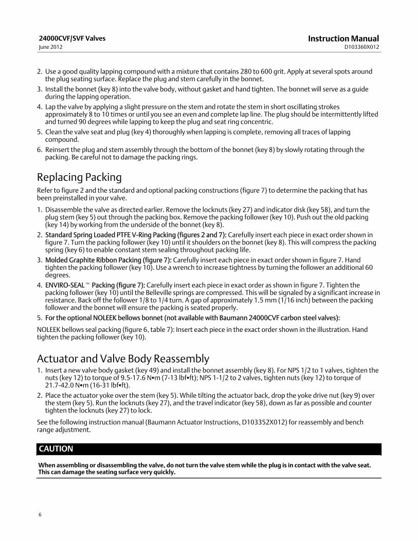
2. Use a good quality lapping compound with amixture that contains 280 to 600 grit. Apply at several spots aroundthe plug seating surface. Replace the plug and stem carefully in the bonnet.
3. Install the bonnet (key 8) into the valve body, without gasket and hand tighten. The bonnet will serve as a guideduring the lapping operation.
4. Lap the valve by applying a slight pressure on the stem and rotate the stem in short oscillating strokesapproximately 8 to 10 times or until you see an even and complete lap line. The plug should be intermittently liftedand turned 90 degrees while lapping to keep the plug and seat ring concentric.
5. Clean the valve seat and plug (key 4) thoroughly when lapping is complete, removing all traces of lappingcompound.
6. Reinsert the plug and stem assembly through the bottom of the bonnet (key 8) by slowly rotating through thepacking. Be careful not to damage the packing rings.
Replacing PackingRefer to figure 2 and the standard and optional packing constructions (figure 7) to determine the packing that hasbeen preinstalled in your valve.
1. Disassemble the valve as directed earlier. Remove the locknuts (key 27) and indicator disk (key 58), and turn theplug stem (key 5) out through the packing box. Remove the packing follower (key 10). Push out the old packing(key 14) by working from the underside of the bonnet (key 8).
2. Standard Spring Loaded PTFE V-Ring Packing (figures 2 and 7): Carefully insert each piece in exact order shown infigure 7. Turn the packing follower (key 10) until it shoulders on the bonnet (key 8). This will compress the packingspring (key 6) to enable constant stem sealing throughout packing life.
3. Molded Graphite Ribbon Packing (figure 7): Carefully insert each piece in exact order shown in figure 7. Handtighten the packing follower (key 10). Use a wrench to increase tightness by turning the follower an additional 60degrees.
4. ENVIRO-SEALt Packing (figure 7): Carefully insert each piece in exact order as shown in figure 7. Tighten thepacking follower (key 10) until the Belleville springs are compressed. This will be signaled by a significant increase inresistance. Back off the follower 1/8 to 1/4 turn. A gap of approximately 1.5mm (1/16 inch) between the packingfollower and the bonnet will ensure the packing is seated properly.
5. For the optional NOLEEK bellows bonnet (not available with Baumann 24000CVF carbon steel valves):
NOLEEK bellows seal packing (figure 6, table 7): Insert each piece in the exact order shown in the illustration. Handtighten the packing follower (key 10).
Actuator and Valve Body Reassembly1. Insert a new valve body gasket (key 49) and install the bonnet assembly (key 8). For NPS 1/2 to 1 valves, tighten thenuts (key 12) to torque of 9.5-17.6 NSm (7-13 lbfSft); NPS 1-1/2 to 2 valves, tighten nuts (key 12) to torque of21.7-42.0 NSm (16-31 lbfSft).
2. Place the actuator yoke over the stem (key 5). While tilting the actuator back, drop the yoke drive nut (key 9) overthe stem (key 5). Run the locknuts (key 27), and the travel indicator (key 58), down as far as possible and countertighten the locknuts (key 27) to lock.
See the following instructionmanual (Baumann Actuator Instructions, D103352X012) for reassembly and benchrange adjustment.
CAUTION
When assembling or disassembling the valve, do not turn the valve stemwhile the plug is in contact with the valve seat.This can damage the seating surface very quickly.
InstructionManualD103360X012
24000CVF/SVF ValvesJune 2012
7
WARNING
To avoid personal injury or equipment damage due to possible sudden shifting or falling of the valve assembly, do not liftthe valve assembly by the handwheel.
Parts OrderingWhen corresponding with your Emerson Process Management sales office about this equipment, always mention thevalve serial number. When ordering replacement parts, also specify the key number, part name, and desiredmaterialusing the following parts tables.
WARNING
Use only genuine Fisherr replacement parts. Components that are not supplied by Emerson ProcessManagement shouldnot, under any circumstances, be used in any Fisher valve, because theymay void yourwarranty, might adversely affect theperformance of the valve, and could cause personal injury and property damage.
InstructionManualD103360X012
24000CVF/SVF ValvesJune 2012
8
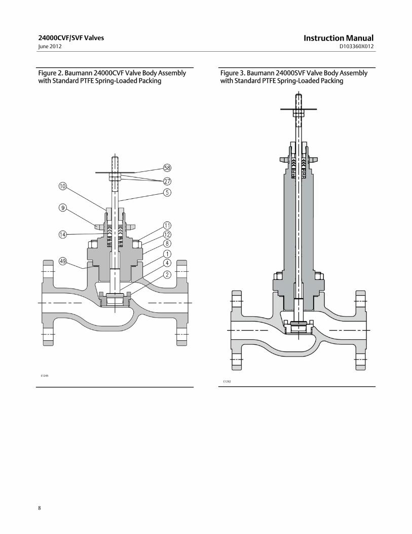
Figure 2. Baumann 24000CVF Valve Body Assemblywith Standard PTFE Spring-Loaded Packing
E1245
Figure 3. Baumann 24000SVF Valve Body Assemblywith Standard PTFE Spring-Loaded Packing
14* 1 V-Ring Packing Set (standard) 24494T001 (See page 13 for additional packing options)
27 2 Locknuts 971514-002-250
49* 1 Valve Body Gasket 24000-133 24000-133 24000-333 24000-533 24000-633
58 1 Travel Indicator 242991. Guide bushing is applicable to 24000CVF valve ONLY.2. Extension bonnets and NOLEEK bellows bonnets are not available with 24000CVF carbon steel valves.
*Recommended spare parts
InstructionManualD103360X012
24000CVF/SVF ValvesJune 2012
10
The guidelines below apply to tables 2, 3, 4, and 6.For Extension Bonnet Construction Double Extension Bonnet Construction Triple Extension Bonnet Construction
Substitute -104 for -101-105 for -102
Substitute -107 for -101-108 for -102
Substitute -110 for -101-111 for -102
Table 2. Plug and Seat Ring for NPS 1/2, 3/4, and 1 Valves
KEYNO.
DESCRIPTION PLUG TYPE PLUG NO.ORIFICEDIAMETERmm (Inch)
Cv KvVALVE SIZE
DN 15 (NPS 1/2) DN 20 (NPS 3/4) DN 25 (NPS 1)
4*Plug & Stem
Assy
Low Flow151 See table 4
177 See table 5
Metal Seat,Micro Trim(Linear)
102 6.3 (0.25)
0.02(1) 0.017(1) GE46385X052 GE46385X092
0.05(1) 0.043(1) GE46386X052 GE46386X092
0.1(1) 0.086(1) GE46387X092 GE46387X052
0.2(1) 0.17(1) GE46388X012 GE46388X092
PTFE Seat(Equal %)
577
9.5 (0.375)
1.0 0.86 24893-101-577
1.5 1.29 24796-101-577
2.5 2.15 24609-101-577
20.6 (0.8125)
4 3.44 24010-2-101-577
6 5.16 24010-101-577 --- ---
7.5 6.45 --- 24010-101-577 ---
8.5 7.31 --- --- 24010-101-577
26.9 (1.0625) 13 11.2 --- --- 24011-101-577
Metal Seat(Equal %)
548(S41600)
6.3 (0.25)
0.22 0.19 GE46393X092 GE46393X052
0.61 0.52 GE46394X092 GE46394X052
1.0 0.86 GE46392X092 GE46392X052
9.5 (0.375)1.5 1.29 24634-6-101-548
2.5 2.15 24171-12-101-548
20.6 (0.8125)
4.7 4.0 24185-6-101-548
6.7 5.76 24061-5-101-548 --- ---
10 8.6 --- 24061-5-101-548
26.9 (1.0625) 15.5 13.33 --- --- 24062-1-101-548
Metal Seat(Equal %) 588
6.3 (0.25)
0.22(1) 0.19(1) GE46390X052 GE46390X092
0.61(1) 0.52(1) GE46391X052 GE46391X092
1.0 0.86 GE46389X052 GE46389X092
9.5 (0.375)1.5 1.29 24634-101-588
2.5 2.15 24171-101-588
20.6 (0.8125)
4.7 4.0 24185-101-588
6.7 5.76 24061-101-588 --- ---
10 8.6 --- 24061-101-588
26.9 (1.0625) 15.5 13.33 --- --- 24062-101-588
Metal Seat(Linear)
648(S41600)
6.3 (0.25)0.5 0.43 GE46398X052 GE46398X092
1.0 0.86 GE46397X052 GE46397X092
9.5 (0.375)1.5 1.29 24669-1-101-648
2.5 2.15 24671-2-101-648
20.6 (0.8125)
4 3.4 24757-5-101-648
6 5.16 24717-3-101-648 --- ---
8 6.88 --- 24717-3-101-648 ---
9 7.74 --- --- 24717-3-101-648
26.9 (1.0625) 13 11.18 --- --- 24791-1-101-648
-continued-
*Recommended spare parts
InstructionManualD103360X012
24000CVF/SVF ValvesJune 2012
11
Table 2. Plug and Seat Ring for NPS 1/2, 3/4, and 1 Valves (continued)
KEYNO.
DESCRIPTION PLUG TYPE PLUG NO.ORIFICEDIAMETERmm (Inch)
Table 10. ENVIRO-SEAL Packing Kit P/N 24490T001Key No. Description Material
13 Bushing, qty 2 Carbon Graphite
14 Packing Set PTFE / carbon-filled PTFE
17 Belleville Spring ASTM B637 N07718
18 Bushing PEEK
19 Washer, qty 2 Modified PTFE
InstructionManualD103360X012
24000CVF/SVF ValvesJune 2012
17
Special ENVIRO-SEAL Packing NoteThe ENVIRO-SEAL PTFE packing system is suitable for 100 ppm environmental applications on services up to 51.7 barg(750 psig) and process temperatures ranging from -46 to 232_C (-50 to 450_F).
For non-environmental applications, this packing system offers excellent performance at the same temperature rangeup to themaximum valve working pressure.
Temperature limits apply to packing arrangements only. Complete valve assembly temperature limits may differ.Refer to appropriate pressure/ temperature ratings.
1. Electric actuators, reference electric actuator bulletins for more details (52.1:ECV, D103347X012 and 52.1:NVACT, D103326X012)
InstructionManualD103360X012
24000CVF/SVF ValvesJune 2012
20
Emerson Process ManagementMarshalltown, Iowa 50158 USASorocaba, 18087 BrazilChatham, Kent ME4 4QZUKDubai, United Arab EmiratesSingapore 128461 Singapore
www.Fisher.com
The contents of this publication are presented for informational purposes only, and while every effort has beenmade to ensure their accuracy, they are notto be construed as warranties or guarantees, express or implied, regarding the products or services described herein or their use or applicability. All sales aregoverned by our terms and conditions, which are available upon request. We reserve the right tomodify or improve the designs or specifications of suchproducts at any time without notice.
E 2009, 2012 Fisher Controls International LLC. All rights reserved.
Baumann, Fisher, FIELDVUE, and ENVIRO-SEAL aremarks owned by one of the companies in the Emerson Process Management business unit of EmersonElectric Co. Emerson Process Management, Emerson, and the Emerson logo are trademarks and servicemarks of Emerson Electric Co. All other marks arethe property of their respective owners.
Neither Emerson, Emerson Process Management, nor any of their affiliated entities assumes responsibility for the selection, use or maintenanceof any product. Responsibility for proper selection, use, andmaintenance of any product remains solely with the purchaser and end user.