62
bee0491x_ch04.qxd 1/4/03 4:12 PM Page 156 mac76 mac76:385_reb:
| Date post: | 24-Apr-2015 |
| Category: |
Documents |
| Upload: | recep-ekici |
| View: | 3,046 times |
| Download: | 23 times |

bee0491x_ch04.qxd 1/4/03 4:12 PM Page 156 mac76 mac76:385_reb:

4
On many nstruction projects, large cranes such as those shown are used. The sum of the moments of the loadsand the counterweights about the base of a crane must be adjusted so that the couple of the reaction at the basedoes not cause failure of the tower.
C H A P T E R
4Equilibrium of Rigid Bodies
bee0491x_ch04_157 1/9/03 4:23 PM Page 157 mac76 mac76:385_reb:

158
EQUILIBRIUM OF RIGID BODIES
4.1 Introduction4.2 Free-Body Diagram
Equilibrium in Two Dimensions4.3 Reactions at Supports and
Connections for a Two-DimensionalStructure
4.4 Equilibrium of a Rigid Body in TwoDimensions
4.5 Statically Indeterminate Reactions.Partial Constraints
4.6 Equilibrium of a Two-Force Body4.7 Equilibrium of a Three-Force Body
Equilibrium in ThreeDimensions
4.8 Equilibrium of a Rigid Body inThree Dimensions
4.9 Reactions at Supports andConnections for a Three-Dimensional Structure
4.1. INTRODUCTION
We saw in the preceding chapter that the external forces acting on arigid body can be reduced to a force-couple system at some arbitrarypoint O. When the force and the couple are both equal to zero, theexternal forces form a system equivalent to zero, and the rigid bodyis said to be in equilibrium.
The necessary and sufficient conditions for the equilibrium of arigid body, therefore, can be obtained by setting R and MR
O equal tozero in the relations (3.52) of Sec. 3.17:
�F � 0 �MO � �(r � F) � 0 (4.1)
Resolving each force and each moment into its rectangular components, we can express the necessary and sufficient conditionsfor the equilibrium of a rigid body with the following six scalar equations:
�Fx � 0 �Fy � 0 �Fz � 0 (4.2)�Mx � 0 �My � 0 �Mz � 0 (4.3)
The equations obtained can be used to determine unknown forces ap-plied to the rigid body or unknown reactions exerted on it by its sup-ports. We note that Eqs. (4.2) express the fact that the componentsof the external forces in the x, y, and z directions are balanced; Eqs.(4.3) express the fact that the moments of the external forces aboutthe x, y, and z axes are balanced. Therefore, for a rigid body in equi-librium, the system of the external forces will impart no translationalor rotational motion to the body considered.
In order to write the equations of equilibrium for a rigid body,it is essential to first identify all of the forces acting on that body andthen to draw the corresponding free-body diagram. In this chapterwe first consider the equilibrium of two-dimensional structures sub-jected to forces contained in their planes and learn how to draw theirfree-body diagrams. In addition to the forces applied to a structure,the reactions exerted on the structure by its supports will be con-sidered. A specific reaction will be associated with each type of sup-port. You will learn how to determine whether the structure is prop-erly supported, so that you can know in advance whether theequations of equilibrium can be solved for the unknown forces andreactions.
Later in the chapter, the equilibrium of three-dimensional struc-tures will be considered, and the same kind of analysis will be givento these structures and their supports.
bee0491x_ch04.qxd 1/4/03 4:12 PM Page 158 mac76 mac76:385_reb:
4.2. Free-Body Diagram 1594.2. FREE-BODY DIAGRAM
In solving a problem concerning the equilibrium of a rigid body, it isessential to consider all of the forces acting on the body; it is equallyimportant to exclude any force which is not directly applied to thebody. Omitting a force or adding an extraneous one would destroy theconditions of equilibrium. Therefore, the first step in the solution ofthe problem should be to draw a free-body diagram of the rigid bodyunder consideration. Free-body diagrams have already been used onmany occasions in Chap. 2. However, in view of their importance tothe solution of equilibrium problems, we summarize here the varioussteps which must be followed in drawing a free-body diagram.
1. A clear decision should be made regarding the choice of thefree body to be used. This body is then detached from theground and is separated from all other bodies. The contourof the body thus isolated is sketched.
2. All external forces should be indicated on the free-body dia-gram. These forces represent the actions exerted on the freebody by the ground and by the bodies which have been de-tached; they should be applied at the various points wherethe free body was supported by the ground or was connectedto the other bodies. The weight of the free body should alsobe included among the external forces, since it represents theattraction exerted by the earth on the various particles form-ing the free body. As will be seen in Chap. 5, the weight shouldbe applied at the center of gravity of the body. When the freebody is made of several parts, the forces the various partsexert on each other should not be included among theexternal forces. These forces are internal forces as far as thefree body is concerned.
3. The magnitudes and directions of the known external forcesshould be clearly marked on the free-body diagram. Whenindicating the directions of these forces, it must be remem-bered that the forces shown on the free-body diagram mustbe those which are exerted on, and not by, the free body.Known external forces generally include the weight of thefree body and forces applied for a given purpose.
4. Unknown external forces usually consist of the reactions,through which the ground and other bodies oppose a possi-ble motion of the free body. The reactions constrain the freebody to remain in the same position, and, for that reason, aresometimes called constraining forces. Reactions are exertedat the points where the free body is supported by or con-nected to other bodies and should be clearly indicated. Re-actions are discussed in detail in Secs. 4.3 and 4.8.
5. The free-body diagram should also include dimensions, sincethese may be needed in the computation of moments offorces. Any other detail, however, should be omitted.
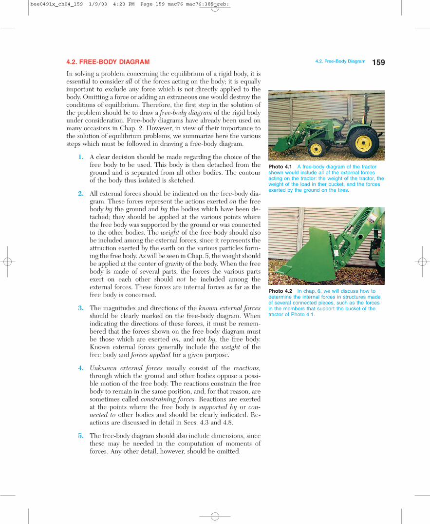
Photo 4.1 A free-body diagram of the tractorshown would include all of the external forcesacting on the tractor: the weight of the tractor, theweight of the load in ther bucket, and the forcesexerted by the ground on the tires.
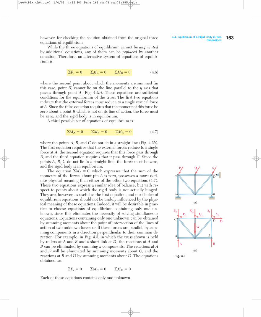
Photo 4.2 In chap. 6, we will discuss how todetermine the internal forces in structures madeof several connected pieces, such as the forcesin the members that support the bucket of thetractor of Photo 4.1.
bee0491x_ch04_159 1/9/03 4:23 PM Page 159 mac76 mac76:385_reb:

EQUILIBRIUM IN TWO DIMENSIONS
4.3. REACTIONS AT SUPPORTS AND CONNECTIONS FOR A TWO-DIMENSIONAL STRUCTURE
In the first part of this chapter, the equilibrium of a two-dimensionalstructure is considered; that is, it is assumed that the structure beinganalyzed and the forces applied to it are contained in the same plane.Clearly, the reactions needed to maintain the structure in the sameposition will also be contained in this plane.
The reactions exerted on a two-dimensional structure can bedivided into three groups corresponding to three types of supports,or connections:
1. Reactions Equivalent to a Force with Known Line of Action.Supports and connections causing reactions of this type in-clude rollers, rockers, frictionless surfaces, short links and ca-bles, collars on frictionless rods, and frictionless pins in slots.Each of these supports and connections can prevent motionin one direction only. They are shown in Fig. 4.1, togetherwith the reactions they produce. Each of these reactions in-volves one unknown, namely, the magnitude of the reaction;this magnitude should be denoted by an appropriate letter.The line of action of the reaction is known and should be in-dicated clearly in the free-body diagram. The sense of the re-action must be as shown in Fig. 4.1 for the cases of a fric-tionless surface (toward the free body) or a cable (away fromthe free body). The reaction can be directed either way inthe case of double-track rollers, links, collars on rods, and pinsin slots. Single-track rollers and rockers are generally assumedto be reversible, and thus the corresponding reactions canalso be directed either way.
2. Reactions Equivalent to a Force of Unknown Direction andMagnitude. Supports and connections causing reactions ofthis type include frictionless pins in fitted holes, hinges, andrough surfaces. They can prevent translation of the free bodyin all directions, but they cannot prevent the body from ro-tating about the connection. Reactions of this group involvetwo unknowns and are usually represented by their x and ycomponents. In the case of a rough surface, the componentnormal to the surface must be directed away from thesurface.
3. Reactions Equivalent to a Force and a Couple. These reac-tions are caused by fixed supports, which oppose any motionof the free body and thus constrain it completely. Fixed sup-ports actually produce forces over the entire surface of con-tact; these forces, however, form a system which can be re-duced to a force and a couple. Reactions of this group involvethree unknowns, consisting usually of the two components ofthe force and the moment of the couple.
160 Equilibrium of Rigid Bodies
Photo 4.3 As the link of the awning windowopening mechanism is extended, the force itexerts on the slider results in a normal forcebeing applied to the rod, which causes thewindow to open.
Photo 4.4 The abutment-mounted rockerbearing shown is used to support the roadway of a bridge.
Photo 4.5 Shown is the rocker expansionbearing of a plate girder bridge. The convexsurface of the rocker allows the support of thegirder to move horizontally.
bee0491x_ch04_160 1/9/03 4:24 PM Page 160 mac76 mac76:385_reb:

4.3. Reactions at Supports and Connectionsfor a Two-Dimensional Structure
When the sense of an unknown force or couple is not readily ap-parent, no attempt should be made to determine it. Instead, the senseof the force or couple should be arbitrarily assumed; the sign of theanswer obtained will indicate whether the assumption is correct ornot.
Support or Connection Reaction Number ofUnknowns
Rollers Rocker Frictionlesssurface
Force with knownline of action
Force with knownline of action
Force with knownline of action
1
1
1
Short cable Short link
Collar onfrictionless rod Frictionless pin in slot
90º
Frictionless pinor hinge
Rough surface Force of unknowndirection
or
or
2
Fixed support Force and couple
3
a
a
Fig. 4.1 Reactions at supports and connections.
161
bee0491x_ch04.qxd 1/4/03 4:12 PM Page 161 mac76 mac76:385_reb:

162 Equilibrium of Rigid Bodies 4.4. EQUILIBRIUM OF A RIGID BODY IN TWO DIMENSIONS
The conditions stated in Sec. 4.1 for the equilibrium of a rigid bodybecome considerably simpler for the case of a two-dimensional struc-ture. Choosing the x and y axes to be in the plane of the structure,we have
Fz � 0 Mx � My � 0 Mz � MO
for each of the forces applied to the structure. Thus, the six equationsof equilibrium derived in Sec. 4.1 reduce to
�Fx � 0 �Fy � 0 �MO � 0 (4.4)
and to three trivial identities, 0 � 0. Since �MO � 0 must be satis-fied regardless of the choice of the origin O, we can write the equa-tions of equilibrium for a two-dimensional structure in the moregeneral form
�Fx � 0 �Fy � 0 �MA � 0 (4.5)
where A is any point in the plane of the structure. The three equa-tions obtained can be solved for no more than three unknowns.
We saw in the preceding section that unknown forces include re-actions and that the number of unknowns corresponding to a givenreaction depends upon the type of support or connection causing thatreaction. Referring to Sec. 4.3, we observe that the equilibrium equa-tions (4.5) can be used to determine the reactions associated with tworollers and one cable, one fixed support, or one roller and one pin ina fitted hole, etc.
Consider Fig. 4.2a, in which the truss shown is subjected to thegiven forces P, Q, and S. The truss is held in place by a pin at A anda roller at B. The pin prevents point A from moving by exerting onthe truss a force which can be resolved into the components Ax andAy; the roller keeps the truss from rotating about A by exerting thevertical force B. The free-body diagram of the truss is shown in Fig.4.2b; it includes the reactions Ax, Ay, and B as well as the appliedforces P, Q, S and the weight W of the truss. Expressing that thesum of the moments about A of all of the forces shown in Fig. 4.2bis zero, we write the equation �MA � 0, which can be used to de-termine the magnitude B since it does not contain Ax or Ay. Next,expressing that the sum of the x components and the sum of the ycomponents of the forces are zero, we write the equations �Fx � 0and �Fy � 0, from which we can obtain the components Ax and Ay,respectively.
An additional equation could be obtained by expressing that thesum of the moments of the external forces about a point other thanA is zero. We could write, for instance, �MB � 0. Such a statement,however, does not contain any new information, since it has alreadybeen established that the system of the forces shown in Fig. 4.2b isequivalent to zero. The additional equation is not independent andcannot be used to determine a fourth unknown. It will be useful,
Fig. 4.2
C
A B
D
P Q S
(a)
C
A B
D
(b)
Py Qy Qx
SySx
W
Px
B
A x
Ay
bee0491x_ch04.qxd 1/4/03 4:12 PM Page 162 mac76 mac76:385_reb:
4.4. Equilibrium of a Rigid Body in TwoDimensions
Fig. 4.3
however, for checking the solution obtained from the original threeequations of equilibrium.
While the three equations of equilibrium cannot be augmentedby additional equations, any of them can be replaced by anotherequation. Therefore, an alternative system of equations of equilib-rium is
�Fx � 0 �MA � 0 �MB � 0 (4.6)
where the second point about which the moments are summed (inthis case, point B) cannot lie on the line parallel to the y axis thatpasses through point A (Fig. 4.2b). These equations are sufficientconditions for the equilibrium of the truss. The first two equationsindicate that the external forces must reduce to a single vertical forceat A. Since the third equation requires that the moment of this force bezero about a point B which is not on its line of action, the force mustbe zero, and the rigid body is in equilibrium.
A third possible set of equations of equilibrium is
�MA � 0 �MB � 0 �MC � 0 (4.7)
where the points A, B, and C do not lie in a straight line (Fig. 4.2b).The first equation requires that the external forces reduce to a singleforce at A; the second equation requires that this force pass throughB; and the third equation requires that it pass through C. Since thepoints A, B, C do not lie in a straight line, the force must be zero,and the rigid body is in equilibrium.
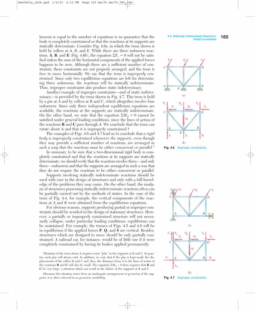
The equation �MA � 0, which expresses that the sum of themoments of the forces about pin A is zero, possesses a more defi-nite physical meaning than either of the other two equations (4.7).These two equations express a similar idea of balance, but with re-spect to points about which the rigid body is not actually hinged.They are, however, as useful as the first equation, and our choice ofequilibrium equations should not be unduly influenced by the phys-ical meaning of these equations. Indeed, it will be desirable in prac-tice to choose equations of equilibrium containing only one un-known, since this eliminates the necessity of solving simultaneousequations. Equations containing only one unknown can be obtainedby summing moments about the point of intersection of the lines ofaction of two unknown forces or, if these forces are parallel, by sum-ming components in a direction perpendicular to their common di-rection. For example, in Fig. 4.3, in which the truss shown is heldby rollers at A and B and a short link at D, the reactions at A andB can be eliminated by summing x components. The reactions at Aand D will be eliminated by summing moments about C, and thereactions at B and D by summing moments about D. The equationsobtained are
�Fx � 0 �MC � 0 �MD � 0
Each of these equations contains only one unknown.
C
A B
D
D
P Q S
(a)
C
A B
D
(b)
Py QyQx
SySx
A
W
Px
B
163
bee0491x_ch04.qxd 1/4/03 4:12 PM Page 163 mac76 mac76:385_reb:

4.5. STATICALLY INDETERMINATE REACTIONS. PARTIALCONSTRAINTS
In the two examples considered in the preceding section (Figs. 4.2and 4.3), the types of supports used were such that the rigid bodycould not possibly move under the given loads or under any otherloading conditions. In such cases, the rigid body is said to be com-pletely constrained. We also recall that the reactions correspondingto these supports involved three unknowns and could be determinedby solving the three equations of equilibrium. When such a situationexists, the reactions are said to be statically determinate.
Consider Fig. 4.4a, in which the truss shown is held by pins at Aand B. These supports provide more constraints than are necessaryto keep the truss from moving under the given loads or under anyother loading conditions. We also note from the free-body diagram ofFig. 4.4b that the corresponding reactions involve four unknowns.Since, as was pointed out in Sec. 4.4, only three independent equi-librium equations are available, there are more unknowns than equa-tions; thus, all of the unknowns cannot be determined. While theequations �MA � 0 and �MB � 0 yield the vertical components By
and Ay, respectively, the equation �Fx � 0 gives only the sum Ax � Bx
of the horizontal components of the reactions at A and B. The com-ponents Ax and Bx are said to be statically indeterminate. They couldbe determined by considering the deformations produced in the trussby the given loading, but this method is beyond the scope of staticsand belongs to the study of mechanics of materials.
The supports used to hold the truss shown in Fig. 4.5a consist ofrollers at A and B. Clearly, the constraints provided by these supportsare not sufficient to keep the truss from moving. While any verticalmotion is prevented, the truss is free to move horizontally. The trussis said to be partially constrained.† Turning our attention to Fig. 4.5b,we note that the reactions at A and B involve only two unknowns.Since three equations of equilibrium must still be satisfied, there arefewer unknowns than equations, and, in general, one of the equilib-rium equations will not be satisfied. While the equations �MA � 0and �MB � 0 can be satisfied by a proper choice of reactions at Aand B, the equation �Fx � 0 will not be satisfied unless the sum ofthe horizontal components of the applied forces happens to be zero.We thus observe that the equlibrium of the truss of Fig. 4.5 cannotbe maintained under general loading conditions.
It appears from the above that if a rigid body is to be completelyconstrained and if the reactions at its supports are to be statically de-terminate, there must be as many unknowns as there are equations ofequilibrium. When this condition is not satisfied, we can be certaineither that the rigid body is not completely constrained or that thereactions at its supports are not statically determinate; it is also pos-sible that the rigid body is not completely constrained and that thereactions are statically indeterminate.
We should note, however, that, while necessary, the above condi-tion is not sufficient. In other words, the fact that the number of un-
164 Equilibrium of Rigid Bodies
Fig. 4.4 Statically indeterminatereactions.
Fig. 4.5 Partial constraints.
C
A B
D
P Q S
(a)
C
A B
D
(b)
Py QyQx
SySx
Bx
By
Ax
Ay
W
Px
C
A B
D
P Q S
(a)
C
A B
D
(b)
Py QyQx
SySx
A
W
Px
B †Partially constrained bodies are often referred to as unstable. However, to avoid confusionbetween this type of instability, due to insufficient constraints, and the type of instabilityconsidered in Chap. 10, which relates to the behavior of a rigid body when its equilibriumis disturbed, we will restrict the use of the words stable and unstable to the latter case.
bee0491x_ch04.qxd 1/4/03 4:12 PM Page 164 mac76 mac76:385_reb:
knowns is equal to the number of equations is no guarantee that thebody is completely constrained or that the reactions at its supports arestatically determinate. Consider Fig. 4.6a, in which the truss shown isheld by rollers at A, B, and E. While there are three unknown reac-tions, A, B, and E (Fig. 4.6b), the equation �Fx � 0 will not be satis-fied unless the sum of the horizontal components of the applied forceshappens to be zero. Although there are a sufficient number of con-straints, these constraints are not properly arranged, and the truss isfree to move horizontally. We say that the truss is improperly con-strained. Since only two equilibrium equations are left for determin-ing three unknowns, the reactions will be statically indeterminate.Thus, improper constraints also produce static indeterminacy.
Another example of improper constraints—and of static indeter-minacy—is provided by the truss shown in Fig. 4.7. This truss is heldby a pin at A and by rollers at B and C, which altogether involve fourunknowns. Since only three independent equilibrium equations areavailable, the reactions at the supports are statically indeterminate.On the other hand, we note that the equation �MA � 0 cannot besatisfied under general loading conditions, since the lines of action ofthe reactions B and C pass through A. We conclude that the truss canrotate about A and that it is improperly constrained.†
The examples of Figs. 4.6 and 4.7 lead us to conclude that a rigidbody is improperly constrained whenever the supports, even thoughthey may provide a sufficient number of reactions, are arranged insuch a way that the reactions must be either concurrent or parallel.‡
In summary, to be sure that a two-dimensional rigid body is com-pletely constrained and that the reactions at its supports are staticallydeterminate, we should verify that the reactions involve three—and onlythree—unknowns and that the supports are arranged in such a way thatthey do not require the reactions to be either concurrent or parallel.
Supports involving statically indeterminate reactions should beused with care in the design of structures and only with a full knowl-edge of the problems they may cause. On the other hand, the analy-sis of structures possessing statically indeterminate reactions often canbe partially carried out by the methods of statics. In the case of thetruss of Fig. 4.4, for example, the vertical components of the reac-tions at A and B were obtained from the equilibrium equations.
For obvious reasons, supports producing partial or improper con-straints should be avoided in the design of stationary structures. How-ever, a partially or improperly constrained structure will not neces-sarily collapse; under particular loading conditions, equilibrium canbe maintained. For example, the trusses of Figs. 4.5 and 4.6 will bein equilibrium if the applied forces P, Q, and S are vertical. Besides,structures which are designed to move should be only partially con-strained. A railroad car, for instance, would be of little use if it werecompletely constrained by having its brakes applied permanently.
4.5. Statically Indeterminate Reactions.Partial Constraints
Fig. 4.6 Improper constraints.
Fig. 4.7 Improper constraints.
C
A BE
E
D
P Q S
(a)
C
A B
D
(b)
Py QyQx
SySx
A
W
Px
BE
B
C
A x
C D
P Q S
(a)
C
A B
A B
D
(b)
Py QyQx
SySx
Ay
W
Px
†Rotation of the truss about A requires some “play” in the supports at B and C. In prac-tice such play will always exist. In addition, we note that if the play is kept small, the dis-placements of the rollers B and C and, thus, the distances from A to the lines of action ofthe reactions B and C will also be small. The equation �MA = 0 then requires that B andC be very large, a situation which can result in the failure of the supports at B and C.
‡Because this situation arises from an inadequate arrangement or geometry of the sup-ports, it is often referred to as geometric instability.
165
bee0491x_ch04.qxd 1/4/03 4:12 PM Page 165 mac76 mac76:385_reb:
166
SAMPLE PROBLEM 4.1
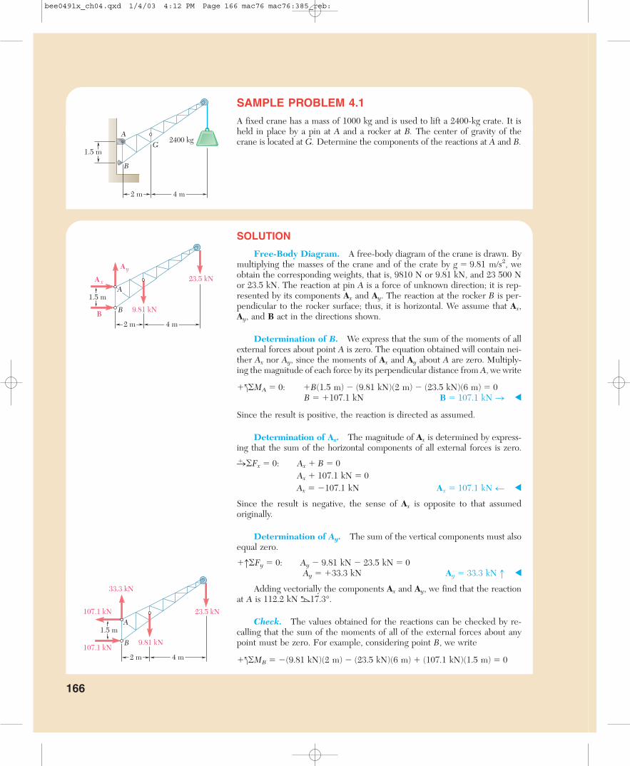
A fixed crane has a mass of 1000 kg and is used to lift a 2400-kg crate. It isheld in place by a pin at A and a rocker at B. The center of gravity of thecrane is located at G. Determine the components of the reactions at A and B.
SOLUTION
Free-Body Diagram. A free-body diagram of the crane is drawn. Bymultiplying the masses of the crane and of the crate by g � 9.81 m/s2, weobtain the corresponding weights, that is, 9810 N or 9.81 kN, and 23 500 Nor 23.5 kN. The reaction at pin A is a force of unknown direction; it is rep-resented by its components Ax and Ay. The reaction at the rocker B is per-pendicular to the rocker surface; thus, it is horizontal. We assume that Ax,Ay, and B act in the directions shown.
Determination of B. We express that the sum of the moments of allexternal forces about point A is zero. The equation obtained will contain nei-ther Ax nor Ay, since the moments of Ax and Ay about A are zero. Multiply-ing the magnitude of each force by its perpendicular distance from A, we write
�l�MA � 0: �B(1.5 m) � (9.81 kN)(2 m) � (23.5 kN)(6 m) � 0B � �107.1 kN B � 107.1 kN n
Since the result is positive, the reaction is directed as assumed.
Determination of Ax. The magnitude of Ax is determined by express-ing that the sum of the horizontal components of all external forces is zero.
n� �Fx � 0: Ax � B � 0Ax � 107.1 kN � 0Ax � �107.1 kN Ax � 107.1 kN m
Since the result is negative, the sense of Ax is opposite to that assumedoriginally.
Determination of Ay. The sum of the vertical components must alsoequal zero.
�h�Fy � 0: Ay � 9.81 kN � 23.5 kN � 0Ay � �33.3 kN Ay � 33.3 kN h
Adding vectorially the components Ax and Ay, we find that the reactionat A is 112.2 kN b17.3°.
Check. The values obtained for the reactions can be checked by re-calling that the sum of the moments of all of the external forces about anypoint must be zero. For example, considering point B, we write
�l�MB � �(9.81 kN)(2 m) � (23.5 kN)(6 m) � (107.1 kN)(1.5 m) � 0
2400 kgA
B
G
4 m2 m
1.5 m
A
BB
23.5 kN
Ay
A x
9.81 kN
1.5 m
4 m2 m
33.3 kN
107.1 kN
107.1 kN
A
B
23.5 kN
9.81 kN
4 m2 m
1.5 m
bee0491x_ch04.qxd 1/4/03 4:12 PM Page 166 mac76 mac76:385_reb:

167
SAMPLE PROBLEM 4.2
Three loads are applied to a beam as shown. The beam is supported by aroller at A and by a pin at B. Neglecting the weight of the beam, determinethe reactions at A and B when P � 15 kips.
SOLUTION
Free-Body Diagram. A free-body diagram of the beam is drawn. Thereaction at A is vertical and is denoted by A. The reaction at B is representedby components Bx and By. Each component is assumed to act in the direc-tion shown.
Equilibrium Equations. We write the following three equilibriumequations and solve for the reactions indicated:
n� �Fx � 0: Bx � 0 Bx � 0
�l�MA � 0:�(15 kips)(3 ft) � By(9 ft) � (6 kips)(11 ft) � (6 kips)(13 ft) � 0
By � �21.0 kips By � 21.0 kips h
�l�MB � 0:�A(9 ft) � (15 kips)(6 ft) � (6 kips)(2 ft) � (6 kips)(4 ft) � 0
A � �6.00 kips A � 6.00 kips h
Check. The results are checked by adding the vertical components ofall of the external forces:
�h�Fy � �6.00 kips � 15 kips � 21.0 kips � 6 kips � 6 kips � 0
Remark. In this problem the reactions at both A and B are vertical;however, these reactions are vertical for different reasons. At A, the beam issupported by a roller; hence the reaction cannot have a horizontal compo-nent. At B, the horizontal component of the reaction is zero because it mustsatisfy the equilibrium equation �Fx � 0 and because none of the other forcesacting on the beam has a horizontal component.
We could have noticed at first glance that the reaction at B was verticaland dispensed with the horizontal component Bx. This, however, is a badpractice. In following it, we would run the risk of forgetting the componentBx when the loading conditions require such a component (i.e., when a hor-izontal load is included). Also, the component Bx was found to be zero byusing and solving an equilibrium equation, �Fx � 0. By setting Bx equal tozero immediately, we might not realize that we actually made use of this equa-tion and thus might lose track of the number of equations available for solv-ing the problem.
3 ft 2 ft 2 ft
6 kips 6 kipsP
6 ft
A B
3 ft 2 ft 2 ft
6 kips15 kips 6 kips
6 ft
By
BxAA
B
bee0491x_ch04.qxd 1/4/03 4:12 PM Page 167 mac76 mac76:385_reb:

168
SAMPLE PROBLEM 4.3
A loading car is at rest on a track forming an angle of 25° with the vertical.The gross weight of the car and its load is 5500 lb, and it is applied at a point30 in. from the track, halfway between the two axles. The car is held by a ca-ble attached 24 in. from the track. Determine the tension in the cable andthe reaction at each pair of wheels.
SOLUTION
Free-Body Diagram. A free-body diagram of the car is drawn. Thereaction at each wheel is perpendicular to the track, and the tension force Tis parallel to the track. For convenience, we choose the x axis parallel to thetrack and the y axis perpendicular to the track. The 5500-lb weight is thenresolved into x and y components.
Wx � �(5500 lb) cos 25° � �4980 lbWy � �(5500 lb) sin 25° � �2320 lb
Equilibrium Equations. We take moments about A to eliminate Tand R1 from the computation.
�l�MA � 0: �(2320 lb)(25 in.) � (4980 lb)(6 in.) � R2(50 in.) � 0R2 � �1758 lb R2 � 1758 lb p
Now, taking moments about B to eliminate T and R2 from the computation,we write
�l�MB � 0: (2320 lb)(25 in.) � (4980 lb)(6 in.) � R1(50 in.) � 0R1 � �562 lb R1 � �562 lb p
The value of T is found by writing
q��Fx � 0: �4980 lb � T � 0T � �4980 lb T � 4980 lb r
The computed values of the reactions are shown in the adjacent sketch.
Check. The computations are verified by writing
p��Fy � �562 lb � 1758 lb � 2320 lb � 0
The solution could also have been checked by computing moments aboutany point other than A or B.
24 in.
25ºG
25 in.
25 in.30 in.
y
x
R1
R2
2320 lb 6 in.
A
T
B
G
25 in.
25 in.
4980 lb
562 lb
1758 lb
y
x
4980 lb
25 in.
25 in.
2320 lb6 in.
A
B
G
4980 lb
bee0491x_ch04.qxd 1/4/03 4:12 PM Page 168 mac76 mac76:385_reb:
169
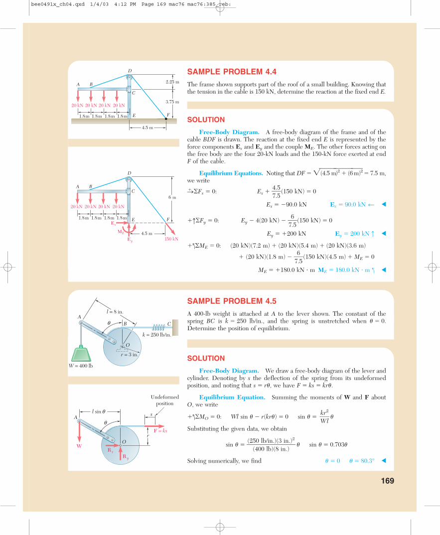
SAMPLE PROBLEM 4.4
The frame shown supports part of the roof of a small building. Knowing thatthe tension in the cable is 150 kN, determine the reaction at the fixed end E.
SOLUTION
Free-Body Diagram. A free-body diagram of the frame and of thecable BDF is drawn. The reaction at the fixed end E is represented by theforce components Ex and Ey and the couple ME. The other forces acting onthe free body are the four 20-kN loads and the 150-kN force exerted at endF of the cable.
Equilibrium Equations. Noting that DF � �(4.5 m�)2 � (6�m)2�� 7.5 m,we write
n� �Fx � 0: Ex � �47..55�(150 kN) � 0
Ex � �90.0 kN Ex � 90.0 kN z
�h�Fy � 0: Ey � 4(20 kN) � �76.5�(150 kN) � 0
Ey � �200 kN Ey � 200 kNx
�l�ME � 0: (20 kN)(7.2 m) � (20 kN)(5.4 m) � (20 kN)(3.6 m)
� (20 kN)(1.8 m) � �76.5�(150 kN)(4.5 m) � ME � 0
ME � �180.0 kN � m ME � 180.0 kN � m l
SAMPLE PROBLEM 4.5
A 400-lb weight is attached at A to the lever shown. The constant of thespring BC is k � 250 lb/in., and the spring is unstretched when � � 0.Determine the position of equilibrium.
SOLUTION
Free-Body Diagram. We draw a free-body diagram of the lever andcylinder. Denoting by s the deflection of the spring from its undeformed position, and noting that s � r�, we have F � ks � kr�.
Equilibrium Equation. Summing the moments of W and F aboutO, we write
�l�MO � 0: Wl sin � � r(kr�) � 0 sin � � �
Substituting the given data, we obtain
sin � ��(25
(400l0b/
libn).()8(3
inin.).)2
� � sin � � 0.703�
Solving numerically, we find � � 0 � � 80.3°
kr2
�Wl
6 m
150 kNEy
Ex
ME
20 kN 20 kN 20 kN 20 kN
A BC
D
E F
4.5 m
1.8 m 1.8 m 1.8 m 1.8 m
As
OW
F = ks
Ry
R x
Undeformedposition
q
r
l sin q
20 kN 20 kN 20 kN 20 kN
A B
C
D
E F1.8 m 1.8 m 1.8 m 1.8 m
2.25 m
3.75 m
4.5 m
AB C
O
k = 250 lb/in.
r = 3 in.
l = 8 in.
W = 400 lb
q
bee0491x_ch04.qxd 1/4/03 4:12 PM Page 169 mac76 mac76:385_reb:
170
S O LV I N G P R O B L E M SO N YO U R O W N
You saw that the external forces acting on a rigid body in equilibrium form a sys-tem equivalent to zero. To solve an equilibrium problem your first task is to drawa neat, reasonably large free-body diagram on which you will show all external forcesand relevant dimensions. Both known and unknown forces must be included.
For a two-dimensional rigid body, the reactions at the supports can involve one,two, or three unknowns depending on the type of support (Fig. 4.1). For the suc-cessful solution of a problem, a correct free-body diagram is essential. Never pro-ceed with the solution of a problem until you are sure that your free-body diagramincludes all loads, all reactions, and the weight of the body (if appropriate).
As you construct your free-body diagrams, it will be necessary to assign directionsto the unknown reactions. We suggest you always assume these forces act in a pos-itive direction, so that positive answers always imply forces acting in a positive di-rection, while negative answers always imply forces acting in a negative direction.Similarly, we recommend you always assume the unknown force in a rod or cableis tensile, so that a positive result always means a tensile reaction. While a negativeor comprehensive reaction is possible for a rod, a negative answer for a cable is im-possible and, therefore, implies that there is an error in your solution.
1. You can write three equilibrium equations and solve them for three un-knowns. The three equations might be
�Fx � 0 �Fy � 0 �MO � 0
However, there are usually several sets of equations that you can write, such as
�Fx � 0 �MA � 0 �MB � 0
where point B is chosen in such a way that the line AB is not parallel to the y axis,or
�MA � 0 �MB � 0 �MC � 0
where the points A, B, and C do not lie in a straight line.
2. To simplify your solution, it may be helpful to use one of the following so-lution techniques if applicable.
a. By summing moments about the point of intersection of the lines of ac-tion of two unknown forces, you will obtain an equation in a single unknown.
bee0491x_ch04.qxd 1/4/03 4:12 PM Page 170 mac76 mac76:385_reb:

b. By summing components in a direction perpendicular to two unknownparallel forces, you will obtain an equation in a single unknown.
In some of the following problems you will be asked to determine the allowable rangeof values of the applied load for a given set of constraints, such as the maximum re-action at a support or the maximum force in one or more cables or rods. For prob-lems of this type, you first assume a maximum loading situation (for example, the max-imum allowed force in a rod), and then apply the equations of equilibrium to determinethe corresponding unknown reactions and applied load. If the reactions satisfy the con-straints, then the applied load is either the maximum or minimum value of the allow-able range. However, if the solution violates a constraint (for example, the force in acable is compressive), the initial assumption is wrong and another loading conditionmust be assumed (for the previous example, you would assume the force in the cableis zero, the minimum allowed reaction). The solution process is then repeated for an-other possible maximum loading to complete the determination of the allowable rangeof values of the applied load.
As in Chap. 2, we strongly recommend you always write the equations of equilib-rium in the same form that we have used in the preceding sample problems. Thatis, both the known and unknown quantities are placed on the left side of the equa-tion, and their sum is set equal to zero.
171
bee0491x_ch04.qxd 1/4/03 4:12 PM Page 171 mac76 mac76:385_reb:
172
Problems
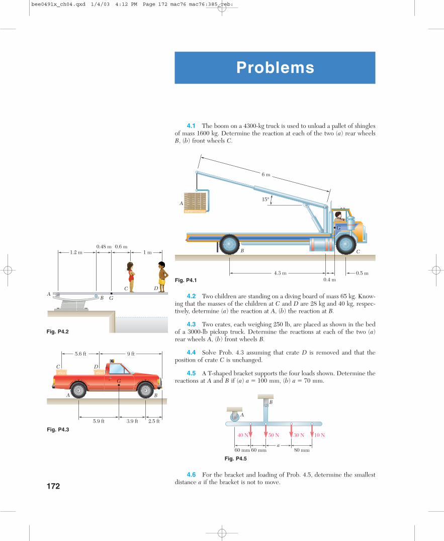
4.1 The boom on a 4300-kg truck is used to unload a pallet of shinglesof mass 1600 kg. Determine the reaction at each of the two (a) rear wheelsB, (b) front wheels C.
A
B C
6 m
15°
4.3 m0.4 m
0.5 m
G
1.2 m
AB G
DC
0.48 m 0.6 m1 m
C D
G
5.6 ft 9 ft
A B
5.9 ft 3.9 ft 2.5 ft
60 mm 60 mm 80 mm
10 N30 N50 N40 N
A
B
a
4.2 Two children are standing on a diving board of mass 65 kg. Know-ing that the masses of the children at C and D are 28 kg and 40 kg, respec-tively, determine (a) the reaction at A, (b) the reaction at B.
4.3 Two crates, each weighing 250 lb, are placed as shown in the bedof a 3000-lb pickup truck. Determine the reactions at each of the two (a)rear wheels A, (b) front wheels B.
4.4 Solve Prob. 4.3 assuming that crate D is removed and that theposition of crate C is unchanged.
4.5 A T-shaped bracket supports the four loads shown. Determine thereactions at A and B if (a) a � 100 mm, (b) a � 70 mm.
4.6 For the bracket and loading of Prob. 4.5, determine the smallestdistance a if the bracket is not to move.
Fig. P4.1
Fig. P4.2
Fig. P4.3
Fig. P4.5
bee0491x_ch04.qxd 1/4/03 4:12 PM Page 172 mac76 mac76:385_reb:

4.7 A hand truck is used to move two barrels, each weighing 80 lb.Neglecting the weight of the hand truck, determine (a) the vertical force Pwhich should be applied to the handle to maintain equilibrium when � � 35°,(b) the corresponding reaction at each of the two wheels.
A
P
B
G1
G28 in.
24 in.
20 in.
32 in.
a
1.5 m
1 m 1 m
0.6 m
A BC D
E G F
0.5 m
1.6 m
400 N
40 mm
60 mm 120 mm
TB TC
O
A B C100 N 200 N 300 N
900 mm
d
A
B
900 mm
a
AD C
B
3 in.150 lb 150 lb
25 lb
4 in.2 in.
6 in.
4.8 Solve Prob. 4.7 when � � 40°.
4.9 Four boxes are placed on a uniform 14-kg wooden plank whichrests on two sawhorses. Knowing that the masses of boxes B and D are 4.5kg and 45 kg, respectively, determine the range of values of the mass of boxA so that the plank remains in equilibrium when box C is removed.
4.10 A control rod is attached to a crank at A and cords are attachedat B and C. For the given force in the rod, determine the range of values ofthe tension in the cord at C knowing that the cords must remain taut andthat the maximum allowed tension in a cord is 180 N.
4.11 The maximum allowable value of each of the reactions is 360 N.Neglecting the weight of the beam, determine the range of values of the dis-tance d for which the beam is safe.
4.12 Solve Prob. 4.11 assuming that the 100-N load is replaced by a160-N load.
4.13 For the beam of Sample Prob. 4.2, determine the range of valuesof P for which the beam will be safe knowing that the maximum allowablevalue of each of the reactions is 45 kips and that the reaction at A must bedirected upward.
4.14 For the beam and loading shown, determine the range of valuesof the distance a for which the reaction at B does not exceed 50 lb down-ward or 100 lb upward.
Fig. P4.7
Fig. P4.9
Fig. P4.10
Fig. P4.14
Fig. P4.11
173Problems
bee0491x_ch04.qxd 1/4/03 4:12 PM Page 173 mac76 mac76:385_reb:

4.15 A follower ABCD is held against a circular cam by a stretchedspring, which exerts a force of 21 N for the position shown. Knowing thatthe tension in rod BE is 14 N, determine (a) the force exerted on the rollerat A, (b) the reaction at bearing C.
4.16 A 6-m-long pole AB is placed in a hole and is guyed by three ca-bles. Knowing that the tensions in cables BD and BE are 442 N and 322 N,respectively, determine (a) the tension in cable CD, (b) the reaction at A.
174 Equilibrium of Rigid Bodies
40 mm
50 mm
20 mm
60°
20 mm
D
C
B E
A
3.15 m
2.10 m
2.8 m
6 m
B E
C
AD
60°
12 in.
10 in. 10 in.
40 lb
GB
Ah
P
A
B
C
D
75 mm
30 mm
40 mm
90°
P
D
A B
C
400 mm
180 mm
60°
40 in.
10 in.
10 in.
80 lb
80 lb
a
AB
C
4.19 The lever BCD is hinged at C and is attached to a control rod atB. If P � 200 N, determine (a) the tension in rod AB, (b) the reaction at C.
4.20 The lever BCD is hinged at C and is attached to a control rod atB. Determine the maximum force P which can be safely applied at D if themaximum allowable value of the reaction at C is 500 N.
4.21 The required tension in cable AB is 800 N. Determine (a) thevertical force P which must be applied to the pedal, (b) the correspondingreaction at C.
4.22 Determine the maximum tension which can be developed in cableAB if the maximum allowable value of the reaction at C is 1000 N.
Fig. P4.15
Fig. P4.18
Fig. P4.16
Fig. P4.17
Fig. P4.19 and P4.20
Fig. P4.21 and P4.22
4.17 Determine the reactions at A and C when (a) � � 0, (b) � � 30°.
4.18 Determine the reactions at A and B when (a) h � 0, (b) h � 8 in.
bee0491x_ch04.qxd 1/4/03 4:12 PM Page 174 mac76 mac76:385_reb:

Problems 175
4.25 A sign is hung by two chains from mast AB. The mast is hingedat A and is supported by cable BD. Knowing that the tensions in chains DEand FH are 50 lb and 30 lb, respectively, and that d � 1.3 ft, determine (a)the tension in cable BC, (b) the reaction at A.
4.26 A sign is hung by two chains from mast AB. The mast is hingedat A and is supported by cable BD. Knowing that the tensions in chains DEand FH are 30 lb and 20 lb, respectively, and that d � 1.54 ft, determine (a)the tension in cable BC, (b) the reaction at A.
4.27 For the frame and loading shown, determine the reactions at Aand E when (a) � � 30°, (b) � � 45°.
6 in.
20 lb
2 in.
45°
9 in.
12 in.
80 lb⋅ in.10 lb
(a)
A
B
6 in.
20 lb
2 in.
9 in.
12 in.
80 lb⋅ in.10 lb
(b)
A
B
45°6 in.
20 lb
2 in.
9 in.
12 in.
80 lb⋅ in.10 lb
(a)
A
B
6 in.
20 lb
2 in.
9 in.
12 in.
80 lb⋅ in.10 lb
(b)
A
B
Fig. P4.23
Fig. P4.24
8.4 ft
2.5 ft
C
A E
DF
H
B
d
2.2 ft5.0 ft
Boat Rentals1/2 hour……………………… $ 5.00 1 hour………$ 7.50 2 hour………$12.50 3 hour………$15.00
Hourly rates
200 mm60 mm
90 N
90 N
100 mm
60 mm
a
A B
DE
C
160 mm
Fig. P4.25 and P4.26
Fig. P4.27
4.23 and 4.24 A steel rod is bent to form a mounting bracket. Foreach of the mounting brackets and loadings shown, determine the reactionsat A and B.
bee0491x_ch04_175 1/11/03 3:18 PM Page 175 mac76 mac76:385_reb:

4.28 A lever AB is hinged at C and is attached to a control cable at A.If the lever is subjected to a 300-N vertical force at B, determine (a) the ten-sion in the cable, (b) the reaction at C.
A
B
D
240 mm
20°300 N
C200 mm
300 mm
B
d
60 mm
40 N
80 mm
180 mm 180 mm
CD
A
A E
C
30 lb
10 in. 10 in.
B D
25 in.
A
BC
R
P
q
4.29 Neglecting friction and the radius of the pulley, determine thetension in cable BCD and the reaction at support A when d � 80 mm.
4.30 Neglecting friction and the radius of the pulley, determine thetension in cable BCD and the reaction at support A when d � 144 mm.
4.31 Neglecting friction, determine the tension in cable ABD and thereaction at support C.
4.32 Rod ABC is bent in the shape of a circular arc of radius R. Know-ing that � � 35°, determine the reaction (a) at B, (b) at C.
4.33 Rod ABC is bent in the shape of a circular arc of radius R. Know-ing that � � 50°, determine the reaction (a) at B, (b) at C.
Fig. P4.28
Fig. P4.29 and P4.30
Fig. P4.31
Fig. P4.32 and P4.33
176 Equilibrium of Rigid Bodies
bee0491x_ch04.qxd 1/4/03 4:12 PM Page 176 mac76 mac76:385_reb:
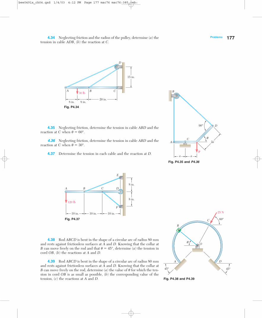
Problems 1774.34 Neglecting friction and the radius of the pulley, determine (a) thetension in cable ADB, (b) the reaction at C.
A B C
15 in.
20 in.8 in. 8 in.
30 lb
D
120 lb
10 in. 10 in. 10 in.
8 in.
8 in.
A B C D
E
F
4.35 Neglecting friction, determine the tension in cable ABD and thereaction at C when � � 60°.
4.36 Neglecting friction, determine the tension in cable ABD and thereaction at C when � � 30°.
4.37 Determine the tension in each cable and the reaction at D.
4.38 Rod ABCD is bent in the shape of a circular arc of radius 80 mmand rests against frictionless surfaces at A and D. Knowing that the collar atB can move freely on the rod and that � � 45°, determine (a) the tension incord OB, (b) the reactions at A and D.
4.39 Rod ABCD is bent in the shape of a circular arc of radius 80 mmand rests against frictionless surfaces at A and D. Knowing that the collar atB can move freely on the rod, determine (a) the value of � for which the ten-sion in cord OB is as small as possible, (b) the corresponding value of thetension, (c) the reactions at A and D.
Fig. P4.34
Fig. P4.37
A
B
D
C
90°
Pa a
2aq
q O
B
C
DA
45° 45°
60°
25 N
Fig. P4.35 and P4.36
Fig. P4.38 and P4.39
bee0491x_ch04.qxd 1/4/03 4:12 PM Page 177 mac76 mac76:385_reb:

4.40 Bar AC supports two 100-lb loads as shown. Rollers A and C restagainst frictionless surfaces and a cable BD is attached at B. Determine (a)the tension in cable BD, (b) the reaction at A, (c) the reaction at C.
100 lb
100 lb
4 in.
6 in.
4 in.12 in.
20 in.
A
B
C
D
10 in.
A B
C D
EF a
60 lb
15 in.
8 in.
5 in.
G
10 in.
120 mm
B
C
D
x
y
AP
Q
140 mm 60 mm 40 mm
46 mm
20 mm
4.41 A parabolic slot has been cut in plate AD, and the plate has beenplaced so that the slot fits two fixed, frictionless pins B and C. The equationof the slot is y � x2�100, where x and y are expressed in mm. Knowing thatthe input force P � 4 N, determine (a) the force each pin exerts on the plate,(b) the output force Q.
4.42 A parabolic slot has been cut in plate AD, and the plate has beenplaced so that the slot fits two fixed, frictionless pins B and C. The equationof the slot is y � x2�100, where x and y are expressed in mm. Knowing thatthe maximum allowable force exerted on the roller at D is 8.5 N, determine(a) the corresponding magnitude of the input force P, (b) the force each pinexerts on the plate.
4.43 A movable bracket is held at rest by a cable attached at E and byfrictionless rollers. Knowing that the width of post FG is slightly less thanthe distance between the rollers, determine the force exerted on the post byeach roller when � � 20°.
4.44 Solve Prob. 4.43 when � � 30°.Fig. P4.43
Fig. P4.40
Fig. P4.41 and P4.42
178 Equilibrium of Rigid Bodies
bee0491x_ch04.qxd 1/4/03 4:12 PM Page 178 mac76 mac76:385_reb:
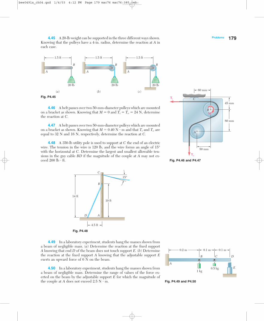
Problems 1794.45 A 20-lb weight can be supported in the three different ways shown.Knowing that the pulleys have a 4-in. radius, determine the reaction at A ineach case.
B
A A A
B B
20 lb 20 lb 20 lb
(a) (b) (c)
1.5 ft 1.5 ft 1.5 ft
A
B
C
D
15°
10 ft14 ft
4.5 ft
4.46 A belt passes over two 50-mm-diameter pulleys which are mountedon a bracket as shown. Knowing that M � 0 and Ti � To � 24 N, determinethe reaction at C.
4.47 A belt passes over two 50-mm-diameter pulleys which are mountedon a bracket as shown. Knowing that M � 0.40 N � m and that Ti and To areequal to 32 N and 16 N, respectively, determine the reaction at C.
4.48 A 350-lb utility pole is used to support at C the end of an electricwire. The tension in the wire is 120 lb, and the wire forms an angle of 15°with the horizontal at C. Determine the largest and smallest allowable ten-sions in the guy cable BD if the magnitude of the couple at A may not ex-ceed 200 lb � ft.
4.49 In a laboratory experiment, students hang the masses shown froma beam of negligible mass. (a) Determine the reaction at the fixed supportA knowing that end D of the beam does not touch support E. (b) Determinethe reaction at the fixed support A knowing that the adjustable support Eexerts an upward force of 6 N on the beam.
4.50 In a laboratory experiment, students hang the masses shown froma beam of negligible mass. Determine the range of values of the force ex-erted on the beam by the adjustable support E for which the magnitude ofthe couple at A does not exceed 2.5 N � m.
Fig. P4.45
Fig. P4.48
50 mm
80 mm
45 mm
60 mm
A
To
Ti
M
C
B
0.5 kg1 kg
A
D
E
CB
0.2 m 0.1 m 0.1 m
Fig. P4.46 and P4.47
Fig. P4.49 and P4.50
bee0491x_ch04.qxd 1/4/03 4:12 PM Page 179 mac76 mac76:385_reb:
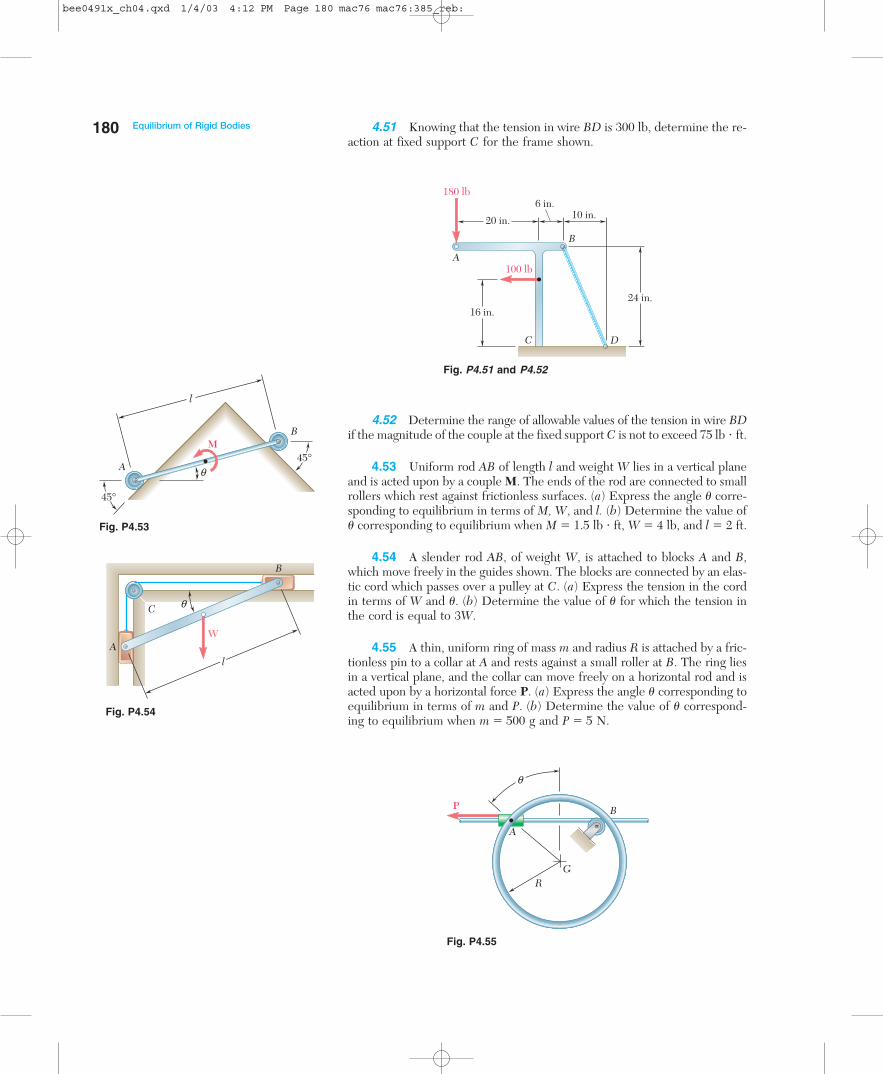
4.51 Knowing that the tension in wire BD is 300 lb, determine the re-action at fixed support C for the frame shown.
180 Equilibrium of Rigid Bodies
180 lb
20 in.
6 in.10 in.
24 in.
100 lbA
B
C D
16 in.
A
MB
45°
45°q
l
A
B
C
W
l
q
4.52 Determine the range of allowable values of the tension in wire BDif the magnitude of the couple at the fixed support C is not to exceed 75 lb � ft.
4.53 Uniform rod AB of length l and weight W lies in a vertical planeand is acted upon by a couple M. The ends of the rod are connected to smallrollers which rest against frictionless surfaces. (a) Express the angle � corre-sponding to equilibrium in terms of M, W, and l. (b) Determine the value of� corresponding to equilibrium when M � 1.5 lb � ft, W � 4 lb, and l � 2 ft.
4.54 A slender rod AB, of weight W, is attached to blocks A and B,which move freely in the guides shown. The blocks are connected by an elas-tic cord which passes over a pulley at C. (a) Express the tension in the cordin terms of W and �. (b) Determine the value of � for which the tension inthe cord is equal to 3W.
4.55 A thin, uniform ring of mass m and radius R is attached by a fric-tionless pin to a collar at A and rests against a small roller at B. The ring liesin a vertical plane, and the collar can move freely on a horizontal rod and isacted upon by a horizontal force P. (a) Express the angle � corresponding toequilibrium in terms of m and P. (b) Determine the value of � correspond-ing to equilibrium when m � 500 g and P � 5 N.
P
q
RG
A
B
Fig. P4.55
Fig. P4.51 and P4.52
Fig. P4.53
Fig. P4.54
bee0491x_ch04.qxd 1/4/03 4:12 PM Page 180 mac76 mac76:385_reb:
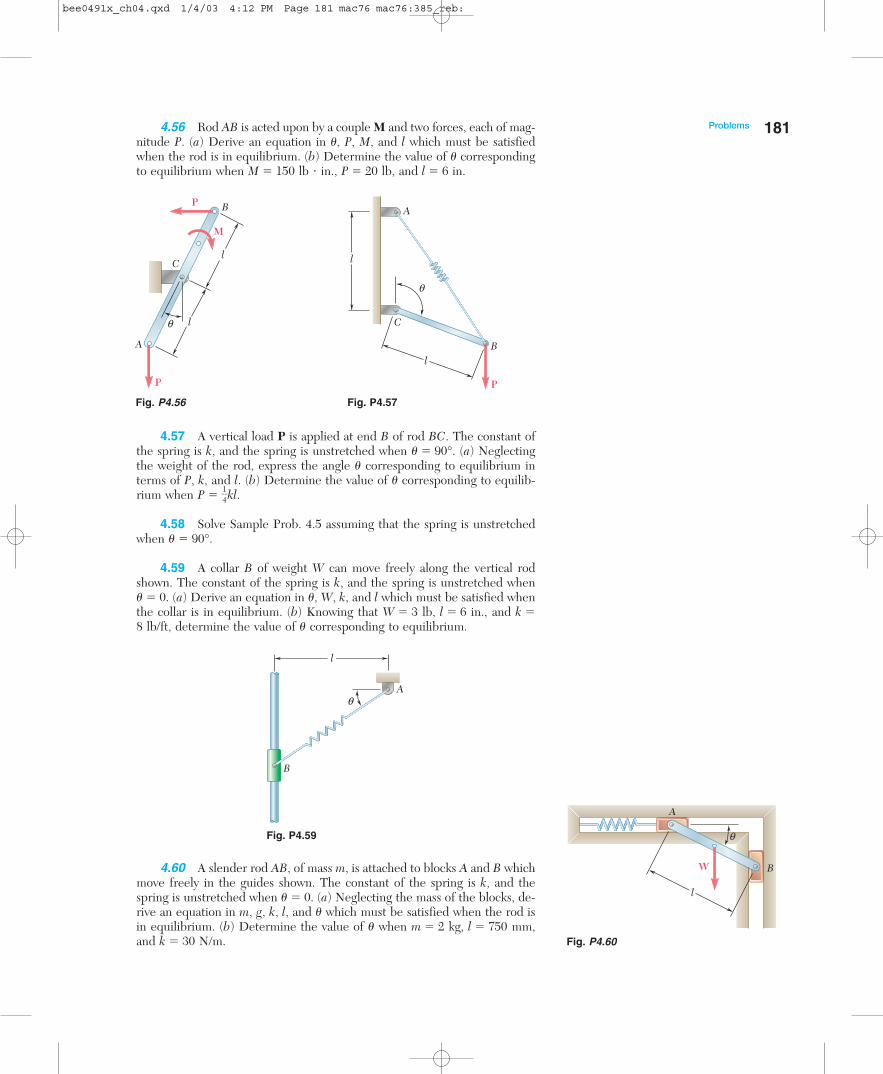
Problems 1814.56 Rod AB is acted upon by a couple M and two forces, each of mag-nitude P. (a) Derive an equation in �, P, M, and l which must be satisfiedwhen the rod is in equilibrium. (b) Determine the value of � correspondingto equilibrium when M � 150 lb � in., P � 20 lb, and l � 6 in.
A
B
C
l
l
P
P
M
q
A
B
C
P
l
l
q
A
B
l
q
4.57 A vertical load P is applied at end B of rod BC. The constant ofthe spring is k, and the spring is unstretched when � � 90°. (a) Neglectingthe weight of the rod, express the angle � corresponding to equilibrium interms of P, k, and l. (b) Determine the value of � corresponding to equilib-rium when P � �
14
�kl.
4.58 Solve Sample Prob. 4.5 assuming that the spring is unstretchedwhen � � 90°.
4.59 A collar B of weight W can move freely along the vertical rodshown. The constant of the spring is k, and the spring is unstretched when� � 0. (a) Derive an equation in �, W, k, and l which must be satisfied whenthe collar is in equilibrium. (b) Knowing that W � 3 lb, l � 6 in., and k �8 lb/ft, determine the value of � corresponding to equilibrium.
Fig. P4.56 Fig. P4.57
Fig. P4.59
4.60 A slender rod AB, of mass m, is attached to blocks A and B whichmove freely in the guides shown. The constant of the spring is k, and thespring is unstretched when � � 0. (a) Neglecting the mass of the blocks, de-rive an equation in m, g, k, l, and � which must be satisfied when the rod isin equilibrium. (b) Determine the value of � when m � 2 kg, l � 750 mm,and k � 30 N/m.
A
BW
l
q
Fig. P4.60
bee0491x_ch04.qxd 1/4/03 4:12 PM Page 181 mac76 mac76:385_reb:
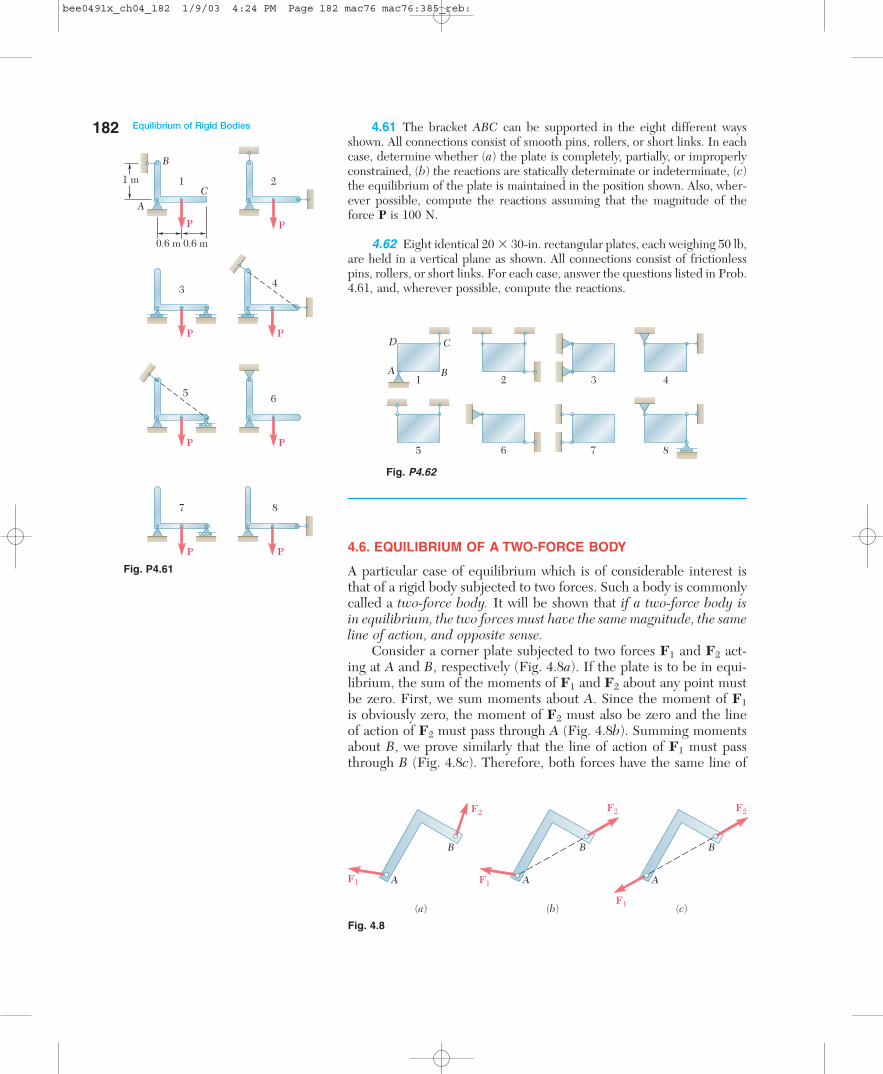
4.61 The bracket ABC can be supported in the eight different waysshown. All connections consist of smooth pins, rollers, or short links. In eachcase, determine whether (a) the plate is completely, partially, or improperlyconstrained, (b) the reactions are statically determinate or indeterminate, (c)the equilibrium of the plate is maintained in the position shown. Also, wher-ever possible, compute the reactions assuming that the magnitude of theforce P is 100 N.
4.62 Eight identical 20 � 30-in. rectangular plates, each weighing 50 lb,are held in a vertical plane as shown. All connections consist of frictionlesspins, rollers, or short links. For each case, answer the questions listed in Prob.4.61, and, wherever possible, compute the reactions.
182 Equilibrium of Rigid Bodies
B
AC
11 m
0.6 m 0.6 m
2
34
5 6
7 8
PP
P
P P
P P
P
A B
CD
1 2 3 4
5 6 7 8
(c)
A
B
F1
F2
(b)
A
B
F2
(a)
A
B
F1
F2
F1
4.6. EQUILIBRIUM OF A TWO-FORCE BODY
A particular case of equilibrium which is of considerable interest isthat of a rigid body subjected to two forces. Such a body is commonlycalled a two-force body. It will be shown that if a two-force body isin equilibrium, the two forces must have the same magnitude, the sameline of action, and opposite sense.
Consider a corner plate subjected to two forces F1 and F2 act-ing at A and B, respectively (Fig. 4.8a). If the plate is to be in equi-librium, the sum of the moments of F1 and F2 about any point mustbe zero. First, we sum moments about A. Since the moment of F1is obviously zero, the moment of F2 must also be zero and the lineof action of F2 must pass through A (Fig. 4.8b). Summing momentsabout B, we prove similarly that the line of action of F1 must passthrough B (Fig. 4.8c). Therefore, both forces have the same line of
Fig. P4.62
Fig. P4.61
Fig. 4.8
bee0491x_ch04_182 1/9/03 4:24 PM Page 182 mac76 mac76:385_reb:

4.7. Equilibrium of a Three-Force Body 183action (line AB). From either of the equations �Fx � 0 and �Fy � 0it is seen that they must also have the same magnitude but oppositesense.
If several forces act at two points A and B, the forces acting at Acan be replaced by their resultant F1 and those acting at B can be re-placed by their resultant F2. Thus a two-force body can be more gen-erally defined as a rigid body subjected to forces acting at only twopoints. The resultants F1 and F2 then must have the same line ofaction, the same magnitude, and opposite sense (Fig. 4.8).
In the study of structures, frames, and machines, you will see howthe recognition of two-force bodies simplifies the solution of certainproblems.
4.7. EQUILIBRIUM OF A THREE-FORCE BODY
Another case of equilibrium that is of great interest is that of a three-force body, that is, a rigid body subjected to three forces or, moregenerally, a rigid body subjected to forces acting at only three points.Consider a rigid body subjected to a system of forces which can bereduced to three forces F1, F2, and F3 acting at A, B, and C, respec-tively (Fig. 4.9a). It will be shown that if the body is in equilibrium,the lines of action of the three forces must be either concurrent orparallel.
Since the rigid body is in equilibrium, the sum of the momentsof F1, F2, and F3 about any point must be zero. Assuming that thelines of action of F1 and F2 intersect and denoting their point of in-tersection by D, we sum moments about D (Fig. 4.9b). Since the mo-ments of F1 and F2 about D are zero, the moment of F3 about Dmust also be zero, and the line of action of F3 must pass through D(Fig. 4.9c). Therefore, the three lines of action are concurrent. Theonly exception occurs when none of the lines intersect; the lines ofaction are then parallel.
Although problems concerning three-force bodies can be solvedby the general methods of Secs. 4.3 to 4.5, the property just estab-lished can be used to solve them either graphically or mathematicallyfrom simple trigonometric or geometric relations.
Fig. 4.9
F2
F3
F1
B C
DA
(a) (b) (c)
F2
F3
F1
B C
DA
F2
F3
F1
B C
A
bee0491x_ch04_183 1/9/03 4:24 PM Page 183 mac76 mac76:385_reb:

184
SAMPLE PROBLEM 4.6
A man raises a 10-kg joist, of length 4 m, by pulling on a rope. Find the ten-sion T in the rope and the reaction at A.
SOLUTION
Free-Body Diagram. The joist is a three-force body, since it is actedupon by three forces: its weight W, the force T exerted by the rope, and thereaction R of the ground at A. We note that
W � mg � (10 kg)(9.81 m/s2) � 98.1 N
Three-Force Body. Since the joist is a three-force body, the forcesacting on it must be concurrent. The reaction R, therefore, will pass throughthe point of intersection C of the lines of action of the weight W and thetension force T. This fact will be used to determine the angle � that R formswith the horizontal.
Drawing the vertical BF through B and the horizontal CD through C,we note that
AF � BF � (AB) cos 45° � (4 m) cos 45° � 2.828 mCD � EF � AE � �
12
�(AF) � 1.414 mBD � (CD) cot (45° � 25°) � (1.414 m) tan 20° � 0.515 mCE � DF � BF � BD � 2.828 m � 0.515 m � 2.313 m
We write
tan � � �CAE
E� � �
21..341134
mm
� � 1.636
� � 58.6°
We now know the direction of all the forces acting on the joist.
Force Triangle. A force triangle is drawn as shown, and its interiorangles are computed from the known directions of the forces. Using the lawof sines, we write
�sin 3
T1.4°� � �
sinR110°� � �
si9n8.
318N.6°
�
T � 81.9 NR � 147.8 N a58.6°
45°
25°4 m
B
A
A
B
C
G
T
R
W = 98.1 Na
45°
45°4 m
A
BC
G
D
E F
25°
a
T
R98.1 N
110°
38.6°
58.6°
20°
31.4°
α =
bee0491x_ch04.qxd 1/4/03 4:12 PM Page 184 mac76 mac76:385_reb:
S O LV I N G P R O B L E M SO N YO U R O W N
The preceding sections covered two particular cases of equilibrium of a rigid body.
1. A two-force body is a body subjected to forces at only two points. Theresultants of the forces acting at each of these points must have the same magni-tude, the same line of action, and opposite sense. This property will allow you tosimplify the solutions of some problems by replacing the two unknown componentsof a reaction by a single force of unknown magnitude but of known direction.
2. A three-force body is subjected to forces at only three points. The re-sultants of the forces acting at each of these points must be concurrent or parallel.To solve a problem involving a three-force body with concurrent forces, draw yourfree-body diagram showing that the lines of action of these three forces pass throughthe same point. The use of geometry will then allow you to complete the solutionusing a force triangle [Sample Prob. 4.6].
Although the principle noted above for the solution of problems involving three-force bodies is easily understood, it can be difficult to determine the needed geo-metric constructions. If you encounter difficulty, first draw a reasonably large free-body diagram and then seek a relation between known or easily calculated lengthsand a dimension that involves an unknown. This was done in Sample Prob. 4.6,where the easily calculated dimensions AE and CE were used to determine the angle �.
185
bee0491x_ch04.qxd 1/4/03 4:12 PM Page 185 mac76 mac76:385_reb:
186
Problems
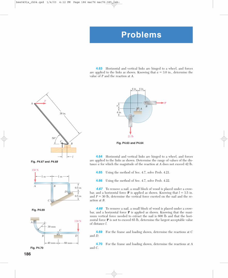
4.63 Horizontal and vertical links are hinged to a wheel, and forcesare applied to the links as shown. Knowing that a � 3.0 in., determine thevalue of P and the reaction at A.
4 in.
21 lb
4 in.
a
4 in.
P
A
C
B
50°
36 in.
AP
CB
l
150 N
1 m 1 m
0.5 m
0.5 mD
BA
C
Fig. P4.63 and P4.64
Fig. P4.67 and P4.68
4.64 Horizontal and vertical links are hinged to a wheel, and forcesare applied to the links as shown. Determine the range of values of the dis-tance a for which the magnitude of the reaction at A does not exceed 42 lb.
4.65 Using the method of Sec. 4.7, solve Prob. 4.21.
4.66 Using the method of Sec. 4.7, solve Prob. 4.22.
4.67 To remove a nail, a small block of wood is placed under a crow-bar, and a horizontal force P is applied as shown. Knowing that l � 3.5 in.and P � 30 lb, determine the vertical force exerted on the nail and the re-action at B.
4.68 To remove a nail, a small block of wood is placed under a crow-bar, and a horizontal force P is applied as shown. Knowing that the maxi-mum vertical force needed to extract the nail is 600 lb and that the hori-zontal force P is not to exceed 65 lb, determine the largest acceptable valueof distance l.
4.69 For the frame and loading shown, determine the reactions at Cand D.
4.70 For the frame and loading shown, determine the reactions at Aand C.
Fig. P4.69
A
B
C
D
130 N
40 mm 60 mm
30 mm
Fig. P4.70
bee0491x_ch04.qxd 1/4/03 4:12 PM Page 186 mac76 mac76:385_reb:
187Problems
90 mm
45 mm35°
20°
360 mm
A B
C
100 N
19 mm
22 mm
150 mm
60°
A
C
B
35°60 N
45 mm
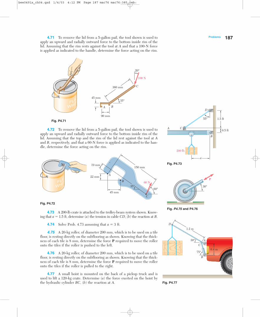
4.71 To remove the lid from a 5-gallon pail, the tool shown is used toapply an upward and radially outward force to the bottom inside rim of thelid. Assuming that the rim rests against the tool at A and that a 100-N forceis applied as indicated to the handle, determine the force acting on the rim.
4.73 A 200-lb crate is attached to the trolley-beam system shown. Know-ing that a � 1.5 ft, determine (a) the tension in cable CD, (b) the reaction at B.
4.74 Solve Prob. 4.73 assuming that a � 3 ft.
4.75 A 20-kg roller, of diameter 200 mm, which is to be used on a tilefloor, is resting directly on the subflooring as shown. Knowing that the thick-ness of each tile is 8 mm, determine the force P required to move the rolleronto the tiles if the roller is pushed to the left.
4.76 A 20-kg roller, of diameter 200 mm, which is to be used on a tilefloor, is resting directly on the subflooring as shown. Knowing that the thick-ness of each tile is 8 mm, determine the force P required to move the rolleronto the tiles if the roller is pulled to the right.
4.77 A small hoist is mounted on the back of a pickup truck and isused to lift a 120-kg crate. Determine (a) the force exerted on the hoist bythe hydraulic cylinder BC, (b) the reaction at A.
Fig. P4.71
Fig. P4.72
Fig. P4.73
A
B
C
D
55°
200 lb
1.5 ft
0.5 ft
a
30°
P
Fig. P4.75 and P4.76
75°
30°
D
CA
B
1.2 m
0.4 m
Fig. P4.77
4.72 To remove the lid from a 5-gallon pail, the tool shown is used toapply an upward and radially outward force to the bottom inside rim of thelid. Assuming that the top and the rim of the lid rest against the tool at Aand B, respectively, and that a 60-N force is applied as indicated to the han-dle, determine the force acting on the rim.
bee0491x_ch04.qxd 1/4/03 4:12 PM Page 187 mac76 mac76:385_reb:

4.78 The clamp shown is used to hold the rough workpiece C. Know-ing that the maximum allowable compressive force on the workpiece is 200N and neglecting the effect of friction at A, determine the corresponding (a)reaction at B, (b) reaction at A, (c) tension in the bolt.
4.79 A modified peavey is used to lift a 0.2-m-diameter log of mass 36 kg. Knowing that � � 45° and that the force exerted at C by the workeris perpendicular to the handle of the peavey, determine (a) the force exertedat C, (b) the reaction at A.
*4.80 A modified peavey is used to lift a 0.2-m-diameter log of mass 36 kg. Knowing that � � 60° and that the force exerted at C by the workeris perpendicular to the handle of the peavey, determine (a) the force exertedat C, (b) the reaction at A.
4.81 Member ABC is supported by a pin and bracket at B and by aninextensible cord attached at A and C and passing over a frictionless pulleyat D. The tension may be assumed to be the same in portion AD and CD ofthe cord. For the loading shown and neglecting the size of the pulley, de-termine the tension in the cord and the reaction at B.
188 Equilibrium of Rigid Bodies
78°
B
A
C 70 mm
105 mm 90 mm
q
1.1 m
C
AB
0.2 m
A
B
CD
300 lb
25 in.
a = 12 in.
16 in.
4.82 Member ABCD is supported by a pin and bracket at C and byan inextensible cord attached at A and D and passing over frictionless pul-leys at B and E. Neglecting the size of the pulleys, determine the tension inthe cord and the reaction at C.
175 mm
375 mm
E
D
B
A
C
200 mm 400 mm
a = 300 mm
80 N
Fig. P4.78
Fig. P4.79 and P4.80
Fig. P4.81
Fig. P4.82
A
BC
R
P
q
Fig. P4.85 and P4.86
4.83 Using the method of Sec. 4.7, solve Prob. 4.18.
4.84 Using the method of Sec. 4.7, solve Prob. 4.28.
4.85 Knowing that � � 35°, determine the reaction (a) at B, (b) at C.
4.86 Knowing that � � 50°, determine the reaction (a) at B, (b) at C.
bee0491x_ch04_188 1/9/03 4:24 PM Page 188 mac76 mac76:385_reb:

Problems 1894.87 A slender rod of length L and weight W is held in equilibrium asshown, with one end against a frictionless wall and the other end attached toa cord of length S. Derive an expression for the distance h in terms of L andS. Show that this position of equilibrium does not exist if S � 2L.
Fig. P4.87 and P4.88
4r
q
3r
P
CB
A r
B
A
CS
L
h
4.88 A slender rod of length L � 200 mm is held in equilibrium asshown, with one end against a frictionless wall and the other end attached toa cord of length S � 300 mm. Knowing that the mass of the rod is 1.5 kg, de-termine (a) the distance h, (b) the tension in the cord, (c) the reaction at B.
4.89 A slender rod of length L and weight W is attached to collarswhich can slide freely along the guides shown. Knowing that the rod is inequilibrium, derive an expression for the angle � in terms of the angle �.
4.90 A 10-kg slender rod of length L is attached to collars which canslide freely along the guides shown. Knowing that the rod is in equilibriumand that � � 25°, determine (a) the angle � that the rod forms with the ver-tical, (b) the reactions at A and B.
4.91 A uniform slender rod of mass 5 g and length 250 mm is balancedon a glass of inner diameter 70 mm. Neglecting friction, determine the an-gle � corresponding to equilibrium.
4.92 Rod AB is bent into the shape of a circular arc and is lodged be-tween two pegs D and E. It supports a load P at end B. Neglecting frictionand the weight of the rod, determine the distance c corresponding to equi-librium when a � 1 in. and R � 5 in.
4.93 A uniform rod AB of weight W and length 2L rests inside a hemi-spherical bowl of radius R as shown. Neglecting friction, determine the an-gle � corresponding to equilibrium.
Fig. P4.94
250 mm
A
C
B
q
P
AR
C
D
E
a
a
c
B
A
B
2R
q
A
B
q
b
L
Fig. P4.89 and P4.90
Fig. P4.91
Fig. P4.92
Fig. P4.93
4.94 A uniform slender rod of mass m and length 4r rests on the sur-face shown and is held in the given equilibrium position by the force P. Ne-glecting the effect of friction at A and C, (a) determine the angle �, (b) de-rive an expression for P in terms of m.
bee0491x_ch04_189 1/9/03 4:24 PM Page 189 mac76 mac76:385_reb:

4.95 A uniform slender rod of length 2L and mass m rests against aroller at D and is held in the equilibrium position shown by a cord of lengtha. Knowing that L � 200 mm, determine (a) the angle �, (b) the length a.
190 Equilibrium of Rigid Bodies
q q
1.25LA
C
a
D2LB
Fig. P4.95
EQUILIBRIUM IN THREE DIMENSIONS
4.8. EQUILIBRIUM OF A RIGID BODY IN THREE DIMENSIONS
We saw in Sec. 4.1 that six scalar equations are required to expressthe conditions for the equilibrium of a rigid body in the general three-dimensional case:
�Fx � 0 �Fy � 0 �Fz � 0 (4.2)�Mx � 0 �My � 0 �Mz � 0 (4.3)
These equations can be solved for no more than six unknowns, whichgenerally will represent reactions at supports or connections.
In most problems the scalar equations (4.2) and (4.3) will be moreconveniently obtained if we first express in vector form the conditionsfor the equilibrium of the rigid body considered. We write
�F � 0 �MO � �(r � F) � 0 (4.1)
and express the forces F and position vectors r in terms of scalar com-ponents and unit vectors. Next, we compute all vector products, eitherby direct calculation or by means of determinants (see Sec. 3.8). Weobserve that as many as three unknown reaction components may beeliminated from these computations through a judicious choice of thepoint O. By equating to zero the coefficients of the unit vectors in eachof the two relations (4.1), we obtain the desired scalar equations.†
4.9. REACTIONS AT SUPPORTS AND CONNECTIONS FOR A THREE-DIMENSIONAL STRUCTURE
The reactions on a three-dimensional structure range from the singleforce of known direction exerted by a frictionless surface to the force-couple system exerted by a fixed support. Consequently, in problemsinvolving the equilibrium of a three-dimensional structure, there canbe between one and six unknowns associated with the reaction at each
†In some problems, it will be found convenient to eliminate the reactions at two pointsA and B from the solution by writing the equilibrium equation �MAB � 0, which involvesthe determination of the moments of the forces about the axis AB joining points A and B(see Sample Prob. 4.10).
bee0491x_ch04.qxd 1/4/03 4:13 PM Page 190 mac76 mac76:385_reb:

4.9. Reactions at Supports and Connectionsfor a Three-Dimensional Structure
191support or connection. Various types of supports and connections areshown in Fig. 4.10 with their corresponding reactions. A simple wayof determining the type of reaction corresponding to a given supportor connection and the number of unknowns involved is to find whichof the six fundamental motions (translation in the x, y, and z direc-tions, rotation about the x, y, and z axes) are allowed and which mo-tions are prevented.
Ball supports, frictionless surfaces, and cables, for example, pre-vent translation in one direction only and thus exert a single force whoseline of action is known; each of these supports involves one unknown,namely, the magnitude of the reaction. Rollers on rough surfaces andwheels on rails prevent translation in two directions; the correspondingreactions consist of two unknown force components. Rough surfaces indirect contact and ball-and-socket supports prevent translation in threedirections; these supports involve three unknown force components.
Some supports and connections can prevent rotation as well astranslation; the corresponding reactions include couples as well asforces. For example, the reaction at a fixed support, which preventsany motion (rotation as well as translation), consists of three unknownforces and three unknown couples. A universal joint, which is designedto allow rotation about two axes, will exert a reaction consisting ofthree unknown force components and one unknown couple.
Other supports and connections are primarily intended to pre-vent translation; their design, however, is such that they also preventsome rotations. The corresponding reactions consist essentially offorce components but may also include couples. One group of sup-ports of this type includes hinges and bearings designed to supportradial loads only (for example, journal bearings, roller bearings). Thecorresponding reactions consist of two force components but may alsoinclude two couples. Another group includes pin-and-bracket sup-ports, hinges, and bearings designed to support an axial thrust as wellas a radial load (for example, ball bearings). The corresponding reac-tions consist of three force components but may include two couples.However, these supports will not exert any appreciable couples un-der normal conditions of use. Therefore, only force componentsshould be included in their analysis unless it is found that couples arenecessary to maintain the equilibrium of the rigid body, or unless thesupport is known to have been specifically designed to exert a couple(see Probs. 4.128 through 4.131).
If the reactions involve more than six unknowns, there are moreunknowns than equations, and some of the reactions are statically in-determinate. If the reactions involve fewer than six unknowns, thereare more equations than unknowns, and some of the equations ofequilibrium cannot be satisfied under general loading conditions; therigid body is only partially constrained. Under the particular loadingconditions corresponding to a given problem, however, the extra equa-tions often reduce to trivial identities, such as 0 � 0, and can be dis-regarded; although only partially constrained, the rigid body remainsin equilibrium (see Sample Probs. 4.7 and 4.8). Even with six or moreunknowns, it is possible that some equations of equilibrium will notbe satisfied. This can occur when the reactions associated with thegiven supports either are parallel or intersect the same line; the rigidbody is then improperly constrained.
Photo 4.6 Universal joints, easily seen on thedrive shafts of rear-wheel-drive cars and trucks,allow rotational motion to be transferred betweentwo non-collinear shafts.
Photo 4.7 The pillow block bearing shownsupports the shaft of a fan used to ventilate afoundry.
bee0491x_ch04_191 1/9/03 4:25 PM Page 191 mac76 mac76:385_reb:

192
Ball Frictionless surface
Force with knownline of action
(one unknown)
Force with knownline of action
(one unknown)Cable
FF
Roller onrough surface
Rough surface
Universaljoint
Hinge and bearing supporting radial load only
Wheel on railTwo force components
Three force components
Three force componentsand one couple
Three force componentsand three couples
Three force components(and two couples)
Two force components(and two couples)
Fy
Fx
Fx
Mx
Fz
Fy
FzFx
Fy
Fz
Fy
Fz
Fy
Fz
My
(Mz)
(My)
(Mz)
(My)
Mz
Ball and socket
Fixed support
Hinge and bearing supportingaxial thrust and radial loadPin and bracket
Fx
Mx
Fy
Fz
Fig. 4.10 Reactions at supports and connections.
bee0491x_ch04.qxd 1/4/03 4:13 PM Page 192 mac76 mac76:385_reb:
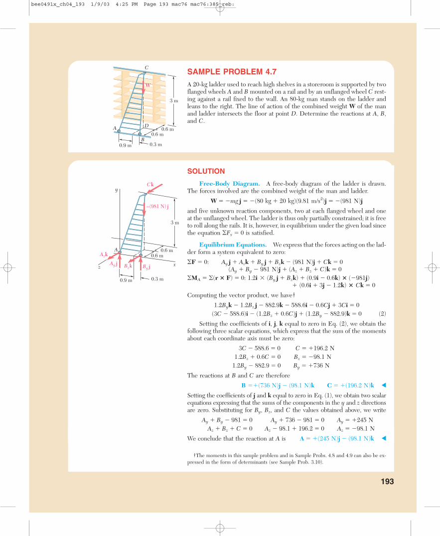
SAMPLE PROBLEM 4.7
A 20-kg ladder used to reach high shelves in a storeroom is supported by twoflanged wheels A and B mounted on a rail and by an unflanged wheel C rest-ing against a rail fixed to the wall. An 80-kg man stands on the ladder andleans to the right. The line of action of the combined weight W of the manand ladder intersects the floor at point D. Determine the reactions at A, B,and C.
SOLUTION
Free-Body Diagram. A free-body diagram of the ladder is drawn.The forces involved are the combined weight of the man and ladder.
W � �mg j � �(80 kg � 20 kg)(9.81 m/s2)j � �(981 N)j
and five unknown reaction components, two at each flanged wheel and oneat the unflanged wheel. The ladder is thus only partially constrained; it is freeto roll along the rails. It is, however, in equilibrium under the given load sincethe equation �Fx � 0 is satisfied.
Equilibrium Equations. We express that the forces acting on the lad-der form a system equivalent to zero:
�F � 0: Ay j � Azk � By j � Bzk � (981 N)j � Ck � 0(Ay � By � 981 N)j � (Az � Bz � C)k � 0
�MA � �(r � F) � 0: 1.2i � (By j � Bzk) � (0.9i � 0.6k) � (�981j)� (0.6i � 3j � 1.2k) � Ck � 0
Computing the vector product, we have†
1.2Byk � 1.2Bz j � 882.9k � 588.6i � 0.6Cj � 3Ci � 0(3C � 588.6)i � (1.2Bz � 0.6C)j � (1.2By � 882.9)k � 0 (2)
Setting the coefficients of i, j, k equal to zero in Eq. (2), we obtain thefollowing three scalar equations, which express that the sum of the momentsabout each coordinate axis must be zero:
3C � 588.6 � 0 C � �196.2 N1.2Bz � 0.6C � 0 Bz � �98.1 N
1.2By � 882.9 � 0 By � �736 N
The reactions at B and C are therefore
B ��(736 N)j � (98.1 N)k C � �(196.2 N)k
Setting the coefficients of j and k equal to zero in Eq. (1), we obtain two scalarequations expressing that the sums of the components in the y and z directionsare zero. Substituting for By, Bz, and C the values obtained above, we write
Ay � By � 981 � 0 Ay � 736 � 981 � 0 Ay � �245 NAz � Bz � C � 0 Az � 98.1 � 196.2 � 0 Az � �98.1 N
We conclude that the reaction at A is A � �(245 N)j � (98.1 N)k
†The moments in this sample problem and in Sample Probs. 4.8 and 4.9 can also be ex-pressed in the form of determinants (see Sample Prob. 3.10).
A
B
C
D0.6 m
0.6 m
0.9 m 0.3 m
W
3 m
A 0.6 m0.6 m
0.9 m 0.3 m
x
y
z
Ck
–(981 N) j
Ay j
Azk
Bzk By j
3 m
193
bee0491x_ch04_193 1/9/03 4:25 PM Page 193 mac76 mac76:385_reb:

SAMPLE PROBLEM 4.8
A 5 � 8-ft sign of uniform density weighs 270 lb and is supported by a ball-and-socket joint at A and by two cables. Determine the tension in each ca-ble and the reaction at A.
SOLUTION
Free-Body Diagram. A free-body diagram of the sign is drawn. Theforces acting on the free body are the weight W � �(270 lb)j and the reactionsat A, B, and E. The reaction at A is a force of unknown direction and is repre-sented by three unknown components. Since the directions of the forces ex-erted by the cables are known, these forces involve only one unknown each,namely, the magnitudes TBD and TEC. Since there are only five unknowns, thesign is partially constrained. It can rotate freely about the x axis; it is, however,in equilibrium under the given loading, since the equation �Mx � 0 is satisfied.
The components of the forces TBD and TEC can be expressed in termsof the unknown magnitudes TBD and TEC by writing
BD�� � �(8 ft)i � (4 ft)j � (8 ft)k BD � 12 ftEC�� � �(6 ft)i � (3 ft)j � (2 ft)k EC � 7 ft
TBD � TBD��BB
D�
D
��� � TBD(��
23
�i � �13
�j � �23
�k)
TEC � TEC��EE
C�
C
��� � TEC(��
67
�i � �37
�j � �27
�k)
Equilibrium Equations. We express that the forces acting on the signform a system equivalent to zero:
�F � 0: Axi � Ay j � Azk � TBD � TEC � (270 lb)j � 0(Ax � �
23
�TBD � �67
�TEC)i � (Ay � �13
�TBD � �37
�TEC � 270 lb)j� (Az � �
23
�TBD � �27
�TEC)k � 0 (1)
�MA � �(r � F) � 0:(8 ft)i � TBD(��
23
�i � �13
�j � �23
�k) � (6 ft)i � TEC(��67
�i � �37
�j � �27
�k)� (4 ft)i � (�270 lb)j � 0
(2.667TBD � 2.571TEC � 1080 lb)k � (5.333TBD � 1.714TEC)j � 0 (2)
Setting the coefficients of j and k equal to zero in Eq. (2), we obtaintwo scalar equations which can be solved for TBD and TEC:
TBD � 101.3 lb TEC � 315 lb
Setting the coefficients of i, j, and k equal to zero in Eq. (1), we obtain threemore equations, which yield the components of A. We have
A � �(338 lb)i � (101.2 lb)j � (22.5 lb)k
194
A
B
C
D
E
x
y
z 6 ft
2 ft
2 ft
5 ft
4 ft
8 ft
3 ft
W = – (270 lb) j
A x i
Azk
A y j
TEC TBDA
B
C
D
E
x
y
z 6 ft
2 ft
2 ft4 ft
4 ft4 ft
8 ft
3 ft
bee0491x_ch04.qxd 1/4/03 4:13 PM Page 194 mac76 mac76:385_reb:

SAMPLE PROBLEM 4.9
A uniform pipe cover of radius r � 240 mm and mass 30 kg is held in a hor-izontal position by the cable CD. Assuming that the bearing at B does notexert any axial thrust, determine the tension in the cable and the reactionsat A and B.
SOLUTION
Free-Body Diagram. A free-body diagram is drawn with the coordi-nate axes shown. The forces acting on the free body are the weight of the cover.
W � �mg j � �(30 kg)(9.81 m/s2)j � �(294 N)j
and reactions involving six unknowns, namely, the magnitude of the force Texerted by the cable, three force components at hinge A, and two at hingeB. The components of T are expressed in terms of the unknown magnitudeT by resolving the vector DC�� into rectangular components and writing
DC�� � �(480 mm)i � (240 mm)j � (160 mm)k DC � 560 mm
T � T � ��67
�Ti � �37
�Tj � �27
�Tk
Equilibrium Equations. We express that the forces acting on thepipe cover form a system equivalent to zero:
�F � 0: Ax i � Ay j � Azk � Bx i � By j � T � (294 N)j � 0(Ax � Bx � �
67
�T)i � (Ay � By � �37
�T � 294 N)j � (Az � �27
�T)k � 0 (1)
�MB � �(r � F) � 0:2rk � (Axi � Ay j � Azk)
� (2ri � rk) � (��67
�Ti � �37
�Tj � �27
�Tk)� (ri � rk) � (�294 N)j � 0
(�2Ay � �37
�T � 294 N)ri � (2Ax � �27
�T)rj � (�67
�T � 294 N)rk � 0 (2)
Setting the coefficients of the unit vectors equal to zero in Eq. (2), wewrite three scalar equations, which yield
Ax � �49.0 N Ay � �73.5 N T � 343 N
Setting the coefficients of the unit vectors equal to zero in Eq. (1), we ob-tain three more scalar equations. After substituting the values of T, Ax, andAy into these equations, we obtain
Az � �98.0 N Bx � �245 N By � �73.5 N
The reactions at A and B are therefore
A � �(49.0 N)i � (73.5 N)j � (98.0 N)kB � �(245 N)i � (73.5 N)j
DC���DC
r = 240 mm
A
B
C
D
160 mm
240 mm240 mm
240 mm
r = 240 mm
A
B
C
D
W = – (294 N) j
Bx iBy j
A x iAyj
Azk
160 mm
80 mm
Tr = 240 mm
r = 240 mm
x
y
z
240 mm
195
bee0491x_ch04.qxd 1/4/03 4:13 PM Page 195 mac76 mac76:385_reb:

SAMPLE PROBLEM 4.10
A 450-lb load hangs from the corner C of a rigid piece ofpipe ABCD which has been bent as shown. The pipe is sup-ported by the ball-and-socket joints A and D, which are fas-tened, respectively, to the floor and to a vertical wall, and bya cable attached at the midpoint E of the portion BC of thepipe and at a point G on the wall. Determine (a) where Gshould be located if the tension in the cable is to be mini-mum, (b) the corresponding minimum value of the tension.
SOLUTION
Free-Body Diagram. The free-body diagram of the pipe includes theload W � (�450 lb)j, the reactions at A and D, and the force T exerted bythe cable. To eliminate the reactions at A and D from the computations, weexpress that the sum of the moments of the forces about AD is zero. De-noting by � the unit vector along AD, we write
�MAD � 0: � � (AE�� � T) � � � (AC�� � W) � 0 (1)
The second term in Eq. (1) can be computed as follows:
AC�� � W � (12i � 12j) � (�450j) � �5400k
� � �AA
DD��� ��
12i � 1128j � 6k�� �
23
�i � �23
�j � �13
�k
� � (AC�� � W) � (�23
�i � �23
�j � �13
�k) � (�5400k) � �1800
Substituting the value obtained into Eq. (1), we write
� � (AE�� � T) � �1800 lb � ft (2)
Minimum Value of Tension. Recalling the commutative property formixed triple products, we rewrite Eq. (2) in the form
T � (� � AE��) � �1800 lb � ft (3)
which shows that the projection of T on the vector � � AE�� is a constant. Itfollows that T is minimum when parallel to the vector
� � AE�� � (�23
�i � �23
�j � �13
�k) � (6i � 12j) � 4i � 2j � 4k
Since the corresponding unit vector is �23
�i � �13
�j � �23
�k, we write
Tmin � T(�23
�i � �13
�j � �23
�k) (4)
Substituting for T and � � AE�� in Eq. (3) and computing the dot products, weobtain 6T � �1800 and, thus, T � �300. Carrying this value into (4), we obtain
Tmin � �200i � 100j � 200k Tmin � 300 lb
Location of G. Since the vector EG�� and the force Tmin have the samedirection, their components must be proportional. Denoting the coordinatesof G by x, y, 0, we write
�x�
�
2006
� � �y�
�
10102
� � �0�
�
2006
� x � 0 y � 15 ft
196
12 ft
12 ft
450 lb
A
BC DE
G
6 ft6 ft
6 ft
A
B C DE
x
y
z
T
�
Dxi
Dy jDzk
A x i
Ay j
Azk
W = –450 j
6 ft
6 ft
12 ft
12 ft
12 ft
A
BC
D
G(x, y, 0)
E(6, 12, 6)
x
y
z
W
Tmin
bee0491x_ch04_196 1/9/03 4:25 PM Page 196 mac76 mac76:385_reb:

S O LV I N G P R O B L E M SO N YO U R O W N
The equilibrium of a three-dimensional body was considered in the sections youjust completed. It is again most important that you draw a complete free-body diagram as the first step of your solution.
1. As you draw the free-body diagram, pay particular attention to the re-actions at the supports. The number of unknowns at a support can range fromone to six (Fig. 4.10). To decide whether an unknown reaction or reaction compo-nent exists at a support, ask yourself whether the support prevents motion of thebody in a certain direction or about a certain axis.
a. If motion is prevented in a certain direction, include in your free-body diagram an unknown reaction or reaction component that acts in the same direction.
b. If a support prevents rotation about a certain axis, include in your free-body diagram a couple of unknown magnitude that acts about the same axis.
2. The external forces acting on a three-dimensional body form a systemequivalent to zero. Writing �F � 0 and �MA � 0 about an appropriate point A,and setting the coefficients of i, j, k in both equations equal to zero will provideyou with six scalar equations. In general, these equations will contain six unknownsand can be solved for these unknowns.
3. After completing your free-body diagram, you may want to seek equa-tions involving as few unknowns as possible. The following strategies mayhelp you.
a. By summing moments about a ball-and-socket support or a hinge, you willobtain equations from which three unknown reaction components have been elim-inated [Sample Probs. 4.8 and 4.9].
b. If you can draw an axis through the points of application of all but one ofthe unknown reactions, summing moments about that axis will yield an equation ina single unknown [Sample Prob. 4.10].
4. After drawing your free-body diagram, we encourage you to comparethe number of unknowns to the number of nontrivial, scalar equations ofequilibrium for the given problem. Doing so will tell you if the body is prop-erly or partially constrained and whether the problem is statically determinate orindeterminate. Further, as we consider more complex problems in later chapters,keeping track of the numbers of unknowns and equations will help you to developcorrect solutions.
197
bee0491x_ch04.qxd 1/4/03 4:13 PM Page 197 mac76 mac76:385_reb:

Problems
4.96 Gears A and B are attached to a shaft supported by bearings atC and D. The diameters of gears A and B are 150 mm and 75 mm, respec-tively, and the tangential and radial forces acting on the gears are as shown.Knowing that the system rotates at a constant rate, determine the reactionsat C and D. Assume that the bearing at C does not exert any axial force, andneglect the weights of the gears and the shaft.
198
B
D1325 N
482 N
964 N
2650 N
100 mm
75 mm
50 mm
x
y
z
E
AC
300 N
T
240 N
180 N
y160 mm
120 mm
A
BC
D
x
z
120 mm
4.97 Solve Prob. 4.96 assuming that for gear A the tangential and ra-dial forces are acting at E, so that FA � (1325 N)j � (482 N)k.
4.98 Two transmission belts pass over sheaves welded to an axle sup-ported by bearings at B and D. The sheave at A has a radius of 50 mm, andthe sheave at C has a radius of 40 mm. Knowing that the system rotates witha constant rate, determine (a) the tension T, (b) the reactions at B and D.Assume that the bearing at D does not exert any axial thrust and neglect theweights of the sheaves and the axle.
Fig. P4.96
Fig. P4.98
bee0491x_ch04.qxd 1/4/03 4:13 PM Page 198 mac76 mac76:385_reb:

4.99 For the portion of a machine shown, the 4-in.-diameter pulley Aand wheel B are fixed to a shaft supported by bearings at C and D. The springof constant 2 lb/in. is unstretched when � � 0, and the bearing at C does notexert any axial force. Knowing that � � 180° and that the machine is at restand in equilibrium, determine (a) the tension T, (b) the reactions at C andD. Neglect the weights of the shaft, pulley, and wheel.
1.2 m
y
z
B
A
x
0.3 m
1.125 m0.9 m
1.5 m
0.9 m
1.2 m
C
y
x
C
A
160 mm
160 mm
40 mm100 mm
100 mm
B
z
12 in.
1 in.
34 lb
T
2 in.
4 in.
6 in.
F
B
D
A
C
y
z
x
3.5 in.
1 in.E
q
Fig. P4.99
Fig. P4.101
Fig. P4.102 and P4.103
4.100 Solve Prob. 4.99 for � � 90°.
4.101 A 1.2 � 2.4-m sheet of plywood having a mass of 17 kg has beentemporarily placed among three pipe supports. The lower edge of the sheetrests on small collars A and B and its upper edge leans against pipe C. Ne-glecting friction at all surfaces, determine the reactions at A, B, and C.
4.102 The 200 � 200-mm square plate shown has a mass of 25 kg andis supported by three vertical wires. Determine the tension in each wire.
4.103 The 200 � 200-mm square plate shown has a mass of 25 kg andis supported by three vertical wires. Determine the mass and location of thelightest block which should be placed on the plate if the tensions in the threecables are to be equal.
199Problems
bee0491x_ch04.qxd 1/4/03 4:13 PM Page 199 mac76 mac76:385_reb:

4.104 A camera of mass 240 g is mounted on a small tripod of mass200 g. Assuming that the mass of the camera is uniformly distributed andthat the line of action of the weight of the tripod passes through D, deter-mine (a) the vertical components of the reactions at A, B, and C when � � 0,(b) the maximum value of � if the tripod is not to tip over.
200 Equilibrium of Rigid Bodies
38 mm
38 mm
35 mm
45 mm
D
A
y
x
C
B
36 mm
120 mm
y
2425
q
Ez
B
A
C
D
y
x
z
a
4 ft2 ft
4.105 Two steel pipes AB and BC, each having a weight per unit lengthof 5 lb/ft, are welded together at B and are supported by three wires. Know-ing that a � 1.25 ft, determine the tension in each wire.
4.106 For the pile assembly of Prob. 4.105, determine (a) the largestpermissible value of a if the assembly is not to tip, (b) the corresponding ten-sion in each wire.
4.107 A uniform aluminum rod of weight W is bent into a circular ringof radius R and is supported by three wires as shown. Determine the ten-sion in each wire.
4.108 A uniform aluminum rod of weight W is bent into a circular ringof radius R and is supported by three wires as shown. A small collar of weightW is then placed on the ring and positioned so that the tensions in the threewires are equal. Determine (a) the position of the collar, (b) the value of W,(c) the tension in the wires.
B
30°C
A
R
y
z x
Fig. P4.105
Fig. P4.104
Fig. P4.107 and P4.108
bee0491x_ch04.qxd 1/4/03 4:13 PM Page 200 mac76 mac76:385_reb:

Problems 2014.109 An opening in a floor is covered by a 3 � 4-ft sheet of plywoodweighing 12 lb. The sheet is hinged at A and B and is maintained in a posi-tion slightly above the floor by a small block C. Determine the vertical com-ponent of the reaction (a) at A, (b) at B, (c) at C.
4 kN
x
y
z
E
AB
C
D
1.2 m1.8 m
2.1 m
1.8 m
1.8 m
y
zx
A
B
E C
0.5 ft
0.5 ft
0.5 ft2 ft
4 ft
D
4.110 Solve Prob. 4.109 assuming that the small block C is moved andplaced under edge DE at a point 0.5 ft from corner E.
4.111 The 10-kg square plate shown is supported by three vertical wires.Determine (a) the tension in each wire when a � 100 mm, (b) the value ofa for which tensions in the three wires are equal.
4.112 The 3-m flagpole AC forms an angle of 30° with the z axis. It isheld by a ball-and-socket joint at C and by two thin braces BD and BE. Know-ing that the distance BC is 0.9 m, determine the tension in each brace andthe reaction at C.
4.113 A 3-m boom is acted upon by the 4-kN force shown. Determinethe tension in each cable and the reaction at the ball-and-socket joint at A.
Fig. P4.109
Fig. P4.113
y
x
B C
A
a
300 mm
a
300 mm
z
A
BC
x
y
z
D
E
300 N
0.9 m
0.9 m
30°0.9 m
Fig. P4.111
Fig. P4.112
bee0491x_ch04_201 1/9/03 4:25 PM Page 201 mac76 mac76:385_reb:
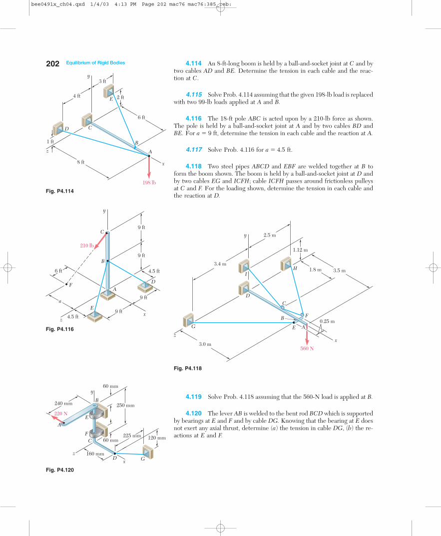
4.114 An 8-ft-long boom is held by a ball-and-socket joint at C and bytwo cables AD and BE. Determine the tension in each cable and the reac-tion at C.
4.115 Solve Prob. 4.114 assuming that the given 198-lb load is replacedwith two 99-lb loads applied at A and B.
4.116 The 18-ft pole ABC is acted upon by a 210-lb force as shown.The pole is held by a ball-and-socket joint at A and by two cables BD andBE. For a � 9 ft, determine the tension in each cable and the reaction at A.
4.117 Solve Prob. 4.116 for a � 4.5 ft.
4.118 Two steel pipes ABCD and EBF are welded together at B toform the boom shown. The boom is held by a ball-and-socket joint at D andby two cables EG and ICFH; cable ICFH passes around frictionless pulleysat C and F. For the loading shown, determine the tension in each cable andthe reaction at D.
202 Equilibrium of Rigid Bodies
2.5 m
3.4 m
3.0 m560 N
D
H
E A
C
FB
G
x
y
z
I
1.12 m
3.5 m1.8 m
0.25 m
240 mm
120 mm
A
GDx
220 N
225 mm
160 mm
250 mm
60 mm
60 mm
E
B
FC
z
y
8 ft
D C
E
B
A
1 ft
198 lb
2 ft4 ft
3 fty
z
x
6 ft
A
B
C
F
x
y
z
D
E
210 lb
4.5 ft
4.5 ft
a
6 ft
9 ft
9 ft
9 ft
9 ft
4.119 Solve Prob. 4.118 assuming that the 560-N load is applied at B.
4.120 The lever AB is welded to the bent rod BCD which is supportedby bearings at E and F and by cable DG. Knowing that the bearing at E doesnot exert any axial thrust, determine (a) the tension in cable DG, (b) the re-actions at E and F.
Fig. P4.118
Fig. P4.114
Fig. P4.116
Fig. P4.120
bee0491x_ch04.qxd 1/4/03 4:13 PM Page 202 mac76 mac76:385_reb:

Problems 2034.121 A 30-kg cover for a roof opening is hinged at corners A and B.The roof forms an angle of 30° with the horizontal, and the cover is main-tained in a horizontal position by the brace CE. Determine (a) the magni-tude of the force exerted by the brace, (b) the reactions at the hinges. As-sume that the hinge at A does not exert any axial thrust.
E
C
D
z
A
y
x
B
1 m
1 m0.8 m
30°
3 in.
54 in.
5 in.
5 in.
D
CE
IB
A
28 in.40 in.
9 in.
10 in.H
yx
z
F
4.122 The rectangular plate shown has a mass of 15 kg and is held inthe position shown by hinges A and B and cable EF. Assuming that the hingeat B does not exert any axial thrust, determine (a) the tension in the cable,(b) the reactions at A and B.
4.123 Solve Prob. 4.122 assuming that cable EF is replaced by a cableattached at points E and H.
4.124 A small door weighing 16 lb is attached by hinges A and B to awall and is held in the horizontal position shown by rope EFH. The ropepasses around a small, frictionless pulley at F and is tied to a fixed cleat atH. Assuming that the hinge at A does not exert any axial thrust, determine(a) the tension in the rope, (b) the reactions at A and B.
4.125 Solve Prob. 4.124 assuming that the rope is attached to the doorat I.
Fig. P4.121
Fig. P4.124
x
y
z
D
H
F
E
A
B
C
250 mm
200 mm
40 mm
120 mm
80 mm
40 mm
300 mm
Fig. P4.122
bee0491x_ch04.qxd 1/4/03 4:13 PM Page 203 mac76 mac76:385_reb:
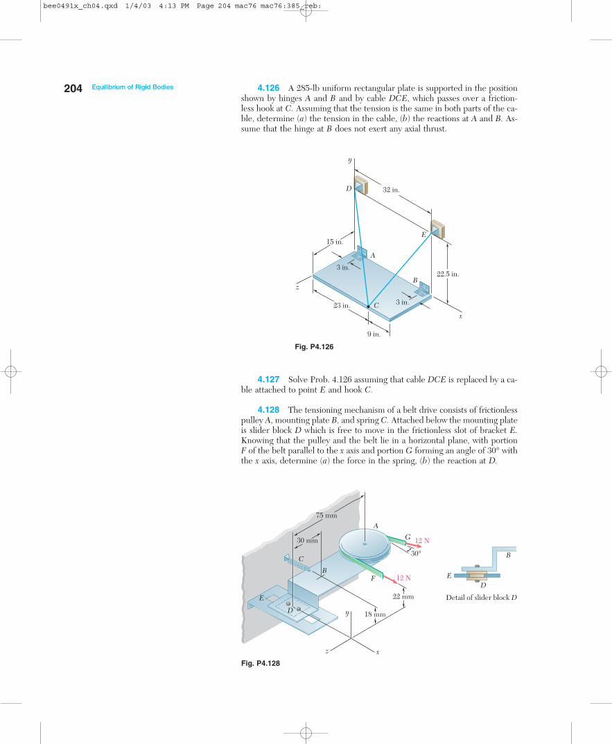
4.126 A 285-lb uniform rectangular plate is supported in the positionshown by hinges A and B and by cable DCE, which passes over a friction-less hook at C. Assuming that the tension is the same in both parts of the ca-ble, determine (a) the tension in the cable, (b) the reactions at A and B. As-sume that the hinge at B does not exert any axial thrust.
204 Equilibrium of Rigid Bodies
12 N
12 N
A
G
FB
E
C
ED
B
y
z x
30 mm
18 mm
22 mm
30°
75 mm
Detail of slider block D
D
23 in.
32 in.
x
y
z
E
D
A
B
C
22.5 in.3 in.
15 in.
9 in.
3 in.
4.127 Solve Prob. 4.126 assuming that cable DCE is replaced by a ca-ble attached to point E and hook C.
4.128 The tensioning mechanism of a belt drive consists of frictionlesspulley A, mounting plate B, and spring C. Attached below the mounting plateis slider block D which is free to move in the frictionless slot of bracket E.Knowing that the pulley and the belt lie in a horizontal plane, with portionF of the belt parallel to the x axis and portion G forming an angle of 30° withthe x axis, determine (a) the force in the spring, (b) the reaction at D.
Fig. P4.126
Fig. P4.128
bee0491x_ch04.qxd 1/4/03 4:13 PM Page 204 mac76 mac76:385_reb:

Problems 2054.129 The assembly shown is welded to collar A which fits on the ver-tical pin shown. The pin can exert couples about the x and z axes but doesnot prevent motion about or along the y axis. For the loading shown, deter-mine the tension in each cable and the reaction at A.
4.130 The lever AB is welded to the bent rod BCD which is supportedby bearing E and by cable DG. Assuming that the bearing can exert an axialthrust and couples about axes parallel to the x and z axes, determine (a) thetension in cable DG, (b) the reaction at E.
240 mm
120 mm
A
GDx
220 N
225 mm
160 mm
250 mm
60 mm
E
B
C
z
y
320 mm200 mm
450 mm
440 mm
I
H
G
D
y
z
x
C
400 mm
200 mm80 mm
420 mm
P
60 mm
A
E
B
F
650 mm
360 N
280 N
4.133 The frame shown is supported by three cables and a ball-and-socket joint at A. For P � 50 N, determine the tension in each cable and thereaction at A.
Fig. P4.130
4.131 Solve Prob. 4.124 assuming that the hinge at A is removed andthat the hinge at B can exert couples about the y and z axes.
4.132 The frame shown is supported by three cables and a ball-and-socket joint at A. For P � 0, determine the tension in each cable and the re-action at A.
Fig. P4.132 and P4.133
800 N
A
C
D
E
F
x
y
z
120 mm
90 mm
180 mm
240 mm
160 mm
Fig. P4.129
bee0491x_ch04.qxd 1/4/03 4:13 PM Page 205 mac76 mac76:385_reb:

4.134 The rigid L-shaped member ABF is supported by a ball-and-socket joint at A and by three cables. For the loading shown, determine thetension in each cable and the reaction at A.
206 Equilibrium of Rigid Bodies
x
y
z
A
B
C D
E F
G
J
H
120 lb
120 lb
13.5 in.
24 in.
24 in.
12 in.
18 in.
24 in.
12 in.
12 in.
12 in.
O
0.5 m x
y
z
A
B
DE
O
3 m1 m
2 m
1 m
C
4.135 Solve Prob. 4.134 assuming that the load at C has been removed.
4.136 In order to clean the clogged drainpipe AE, a plumber has dis-connected both ends of the pipe and inserted a power snake through theopening at A. The cutting head of the snake is connected by a heavy cableto an electric motor which rotates at a constant speed as the plumber forcesthe cable into the pipe. The forces exerted by the plumber and the motoron the end of the cable can be represented by the wrench F � �(60 N)k,M � �(108 N � m)k. Determine the additional reactions at B, C, and Dcaused by the cleaning operation. Assume that the reaction at each supportconsists of two force components perpendicular to the pipe.
Fig. P4.134
Fig. P4.136
bee0491x_ch04.qxd 1/4/03 4:13 PM Page 206 mac76 mac76:385_reb:

Problems 2074.137 Solve Prob. 4.136 assuming that the plumber exerts a force F � �(60 N)k and that the motor is turned off (M � 0).
4.138 Three rods are welded together to form a “corner’’ which is sup-ported by three eyebolts. Neglecting friction, determine the reactions at A,B, and C when P � 240 N, a � 120 mm, b � 80 mm, and c � 100 mm.
x
y
z
b
cA
B
C
P
a
x
y
z
A
B
C
DE
18 in.
8 in.
24 in.
24 in.
40 in.
4.141 A 21-in.-long uniform rod AB weighs 6.4 lb and is attached toa ball-and-socket joint at A. The rod rests against an inclined frictionless sur-face and is held in the position shown by cord BC. Knowing that the cord is21 in. long, determine (a) the tension in the cord, (b) the reactions at A and B.
Fig. P4.138
Fig. P4.140
4.139 Solve Prob. 4.138 assuming that the force P is removed and isreplaced by a couple M � �(6 N � m)j acting at B.
4.140 The uniform 10-lb rod AB is supported by a ball-and-socket jointat A and leans against both the rod CD and the vertical wall. Neglecting theeffects of friction, determine (a) the force which rod CD exerts on AB, (b)the reactions at A and B. (Hint: The force exerted by CD on AB must beperpendicular to both rods.)
26 in.
C
A
B
13 in.
5 in.
x
y
z
3
4
Fig. P4.141
bee0491x_ch04.qxd 1/4/03 4:13 PM Page 207 mac76 mac76:385_reb:

208 Equilibrium of Rigid Bodies
18 in.
50 in.
144 in.
34 in. 50 in.
42 in.
F
E
A
D
G
I
B
CH
J
z
y
x
36 in.28 in.
50 in.
97 in.
B
4.144 To water seedlings, a gardener joins three lengths of pipe, AB,BC, and CD, fitted with spray nozzles and suspends the assembly usinghinged supports at A and D and cable EF. Knowing that the pipe weighs0.85 lb/ft, determine the tension in the cable.
4.145 Solve Prob. 4.144 assuming that cable EF is replaced by a cableconnecting E and C.
3 ftE
y
D
B
C
A
F
4 ft
4.5 ft
2 ft
2 ft
zx
1 ft
Fig. P4.142 and P4.143
Fig. P4.144
4.142 While being installed, the 56-lb chute ABCD is attached to a wallwith brackets E and F and is braced with props GH and IJ. Assuming thatthe weight of the chute is uniformly distributed, determine the magnitudeof the force exerted on the chute by prop GH if prop IJ is removed.
4.143 While being installed, the 56-lb chute ABCD is attached to awall with brackets E and F and is braced with props GH and IJ. Assumingthat the weight of the chute is uniformly distributed, determine the magni-tude of the force exerted on the chute by prop IJ if prop GH is removed.
bee0491x_ch04.qxd 1/4/03 4:13 PM Page 208 mac76 mac76:385_reb:

Problems 209
x
y
z
A
B
C
D
E
F
80 mm
70 mm
90 mm
600 N110 mm
160 mm
100 mm
140 mm
Fig. P4.146
4.146 The bent rod ABDE is supported by ball-and-socket joints at Aand E and by the cable DF. If a 600-N load is applied at C as shown, deter-mine the tension in the cable.
4.147 Solve Prob. 4.146 assuming that cable DF is replaced by a cableconnecting B and F.
B
A
y
z
D
Cx
60 mm
120 mm80 mm
90 mm
200 N
y
zx
B
C
16 in.
12 in.
4 in.28 in.
D
A
4.148 Two rectangular plates are welded together to form the assem-bly shown. The assembly is supported by ball-and-socket joints at B and Dand by a ball on a horizontal surface at C. For the loading shown, determinethe reaction at C.
4.149 Two 1 � 2-m plywood panels, each of mass 15 kg, are nailed to-gether as shown. The panels are supported by ball-and-socket joints at A and Fand by the wire BH. Determine (a) the location of H in the xy plane if the ten-sion in the wire is to be minimum, (b) the corresponding minimum tension.
4.150 Solve Prob. 4.149 subject to the restriction that H must lie onthe y axis.
4.151 A uniform 20 � 30-in. steel plate ABCD weighs 85 lb and is at-tached to ball-and-socket joints at A and B. Knowing that the plate leansagainst a frictionless vertical wall at D, determine (a) the location of D, (b)the reaction at D.
Fig. P4.148
Fig. P4.151
z 1 m
2 m 2 m
x
x
y
y
A
B
C
O
H
D
E
F
Fig. P4.149
bee0491x_ch04.qxd 1/4/03 4:13 PM Page 209 mac76 mac76:385_reb:

210
Equilibrium equations
Free-body diagram
R E V I E W A N D S U M M A R YF O R C H A P T E R 4
This chapter was devoted to the study of the equilibrium of rigidbodies, that is, to the situation when the external forces acting on arigid body form a system equivalent to zero [Sec. 4.1]. We then have
�F � 0 �MO � �(r � F) � 0 (4.1)
Resolving each force and each moment into its rectangularcomponents, we can express the necessary and sufficient condi-tions for the equilibrium of a rigid body with the following six scalarequations:
�Fx � 0 �Fy � 0 �Fz � 0 (4.2)�Mx � 0 �My � 0 �Mz � 0 (4.3)
These equations can be used to determine unknown forces appliedto the rigid body or unknown reactions exerted by its supports.
When solving a problem involving the equilibrium of a rigidbody, it is essential to consider all of the forces acting on the body.Therefore, the first step in the solution of the problem should be todraw a free-body diagram showing the body under consideration andall of the unknown as well as known forces acting on it [Sec. 4.2].
In the first part of the chapter, we considered the equilibriumof a two-dimensional structure; that is, we assumed that the struc-ture considered and the forces applied to it were contained in thesame plane. We saw that each of the reactions exerted on the struc-ture by its supports could involve one, two, or three unknowns, de-pending upon the type of support [Sec. 4.3].
In the case of a two-dimensional structure, Eqs. (4.1), or Eqs.(4.2) and (4.3), reduce to three equilibrium equations, namely
�Fx � 0 �Fy � 0 �MA � 0 (4.5)
where A is an arbitrary point in the plane of the structure [Sec.4.4]. These equations can be used to solve for three unknowns.While the three equilibrium equations (4.5) cannot be augmentedwith additional equations, any of them can be replaced by anotherequation. Therefore, we can write alternative sets of equilibriumequations, such as
�Fx � 0 �MA � 0 �MB � 0 (4.6)
where point B is chosen in such a way that the line AB is not parallelto the y axis, or
�MA � 0 �MB � 0 �MC � 0 (4.7)
where the points A, B, and C do not lie in a straight line.
Equilibrium of a two-dimensional structure
bee0491x_ch04.qxd 1/4/03 4:13 PM Page 210 mac76 mac76:385_reb:
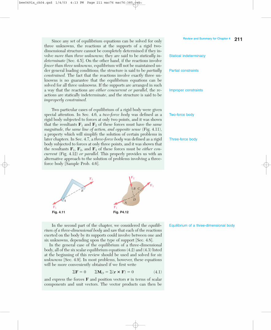
Since any set of equilibrium equations can be solved for onlythree unknowns, the reactions at the supports of a rigid two-dimensional structure cannot be completely determined if they in-volve more than three unknowns; they are said to be statically in-determinate [Sec. 4.5]. On the other hand, if the reactions involvefewer than three unknowns, equilibrium will not be maintained un-der general loading conditions; the structure is said to be partiallyconstrained. The fact that the reactions involve exactly three un-knowns is no guarantee that the equilibrium equations can besolved for all three unknowns. If the supports are arranged in sucha way that the reactions are either concurrent or parallel, the re-actions are statically indeterminate, and the structure is said to beimproperly constrained.
Two particular cases of equilibrium of a rigid body were givenspecial attention. In Sec. 4.6, a two-force body was defined as arigid body subjected to forces at only two points, and it was shownthat the resultants F1 and F2 of these forces must have the samemagnitude, the same line of action, and opposite sense (Fig. 4.11),a property which will simplify the solution of certain problems inlater chapters. In Sec. 4.7, a three-force body was defined as a rigidbody subjected to forces at only three points, and it was shown thatthe resultants F1, F2, and F3 of these forces must be either con-current (Fig. 4.12) or parallel. This properly provides us with analternative approach to the solution of problems involving a three-force body [Sample Prob. 4.6].
A
B
F1
F2F2
F3
F1
B C
DA
Fig. 4.11 Fig. P4.12
In the second part of the chapter, we considered the equilib-rium of a three-dimensional body and saw that each of the reactionsexerted on the body by its supports could involve between one andsix unknowns, depending upon the type of support [Sec. 4.8].
In the general case of the equilibrium of a three-dimensionalbody, all of the six scalar equilibrium equations (4.2) and (4.3) listedat the beginning of this review should be used and solved for sixunknowns [Sec. 4.9]. In most problems, however, these equationswill be more conveniently obtained if we first write
�F � 0 �MO � �(r � F) � 0 (4.1)
and express the forces F and position vectors r in terms of scalarcomponents and unit vectors. The vector products can then be
Statical indeterminacy
Partial constraints
Improper constraints
Two-force body
Three-force body
Equilibrium of a three-dimensional body
Review and Summary for Chapter 4 211
bee0491x_ch04.qxd 1/4/03 4:13 PM Page 211 mac76 mac76:385_reb:
computed either directly or by means of determinants, and the de-sired scalar equations obtained by equating to zero the coefficientsof the unit vectors [Sample Probs. 4.7 through 4.9].
We noted that as many as three unknown reaction componentsmay be eliminated from the computation of �MO in the second ofthe relations (4.1) through a judicious choice of point O. Also, thereactions at two points A and B can be eliminated from the solu-tion of some problems by writing the equation MAB � 0, whichinvolves the computation of the moments of the forces about anaxis AB joining points A and B [Sample Prob. 4.10].
If the reactions involve more than six unknowns, some of thereactions are statically indeterminate; if they involve fewer than sixunknowns, the rigid body is only partially constrained. Even withsix or more unknowns, the rigid body will be improperly con-strained if the reactions associated with the given supports eitherare parallel or intersect the same line.
212 Equilibrium of Rigid Bodies
bee0491x_ch04.qxd 1/4/03 4:13 PM Page 212 mac76 mac76:385_reb:
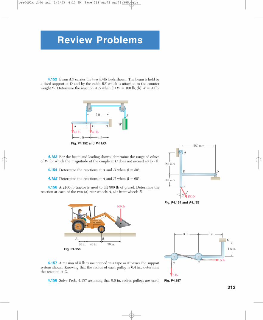
213
20 in. 40 in. 50 in.
900 lb
A B
G
4.157 A tension of 5 lb is maintained in a tape as it passes the supportsystem shown. Knowing that the radius of each pulley is 0.4 in., determinethe reaction at C.
4.158 Solve Prob. 4.157 assuming that 0.6-in.-radius pulleys are used.
Fig. P4.156
A B C D
40 lb 40 lb
E5 ft
4 ft4 ft
W
Review Problems
4.152 Beam AD carries the two 40-lb loads shown. The beam is held bya fixed support at D and by the cable BE which is attached to the counterweight W. Determine the reaction at D when (a) W � 100 lb, (b) W � 90 lb.
4.153 For the beam and loading shown, determine the range of valuesof W for which the magnitude of the couple at D does not exceed 40 lb � ft.
4.154 Determine the reactions at A and D when � � 30°.
4.155 Determine the reactions at A and D when � � 60°.
4.156 A 2100-lb tractor is used to lift 900 lb of gravel. Determine thereaction at each of the two (a) rear wheels A, (b) front wheels B.
Fig. P4.152 and P4.153
C
5 lb
5 lb
3 in. 3 in.
1.8 in.
A B
Fig. P4.157
A
B
C
D
150 N
180 mm
100 mm
280 mm
b
Fig. P4.154 and P4.155
bee0491x_ch04.qxd 1/4/03 4:13 PM Page 213 mac76 mac76:385_reb:
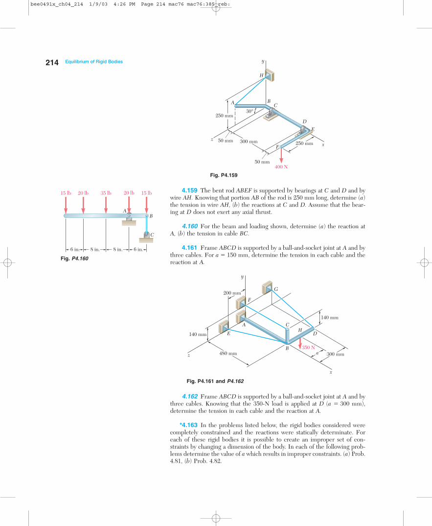
250 mm50 mm 300 mm
400 N
C
D
E
F xz
50 mm
250 mm
A B
H
y
30°
A
B
CH
DE
F
G
x
y
z
140 mm
350 N300 mm
140 mm
200 mm
a480 mm
A
C
B
15 lb 20 lb 35 lb 15 lb20 lb
6 in. 8 in. 8 in. 6 in.
4.159 The bent rod ABEF is supported by bearings at C and D and bywire AH. Knowing that portion AB of the rod is 250 mm long, determine (a)the tension in wire AH, (b) the reactions at C and D. Assume that the bear-ing at D does not exert any axial thrust.
4.160 For the beam and loading shown, determine (a) the reaction atA, (b) the tension in cable BC.
4.161 Frame ABCD is supported by a ball-and-socket joint at A and bythree cables. For a � 150 mm, determine the tension in each cable and thereaction at A.
4.162 Frame ABCD is supported by a ball-and-socket joint at A and bythree cables. Knowing that the 350-N load is applied at D (a � 300 mm),determine the tension in each cable and the reaction at A.
*4.163 In the problems listed below, the rigid bodies considered werecompletely constrained and the reactions were statically determinate. Foreach of these rigid bodies it is possible to create an improper set of con-straints by changing a dimension of the body. In each of the following prob-lems determine the value of a which results in improper constraints. (a) Prob.4.81, (b) Prob. 4.82.
Fig. P4.161 and P4.162
Fig. P4.159
Fig. P4.160
214 Equilibrium of Rigid Bodies
bee0491x_ch04_214 1/9/03 4:26 PM Page 214 mac76 mac76:385_reb:

215
Fig. P4.C1
Fig. P4.C2
Computer Problems
4.C1 A slender rod AB of weight W is attached to blocks at A and Bwhich can move freely in the guides shown. The constant of the spring is kand the spring is unstretched when the rod is horizontal. Neglecting theweight of the blocks, derive an equation in terms of (�, W, l, and k whichmust be satisfied when the rod is in equilibrium. Knowing that W � 10 lband l � 40 in., (a) calculate and plot the value of the spring constant k as afunction of the angle � for 15� � � � 40�, (b) determine the two values ofthe angle � corresponding to equilibrium when k � 0.7 lb/in.
A
B
C
W
q
l
4.C2 The position of the L-shaped rod shown is controlled by a cableattached at point B. Knowing that the rod supports a load of magnitude P �200 N, use computational software to calculate and plot the tension T in thecable as a function of � for values of � from from 0 to 120�. Determine themaximum tension Tmax and the corresponding value of �.
4.C3 The position of the 20-lb rod AB is controlled by the block shown,which is slowly moved to the left by the force P. Neglecting the effect of fric-tion, use computational software to calculate and plot the magnitude P of theforce as a function of x for values of x decreasing from 30 in. to 0. Deter-mine the maximum value of P and the corresponding value of x.
E
A
BD
C
T
P
q
160 mm
320 mm
240 mm
300 mm
80 mm
Fig. P4.C3
A
B
D P16 in.
x
40 in.
bee0491x_ch04_215 1/9/03 4:26 PM Page 215 mac76 mac76:385_reb:
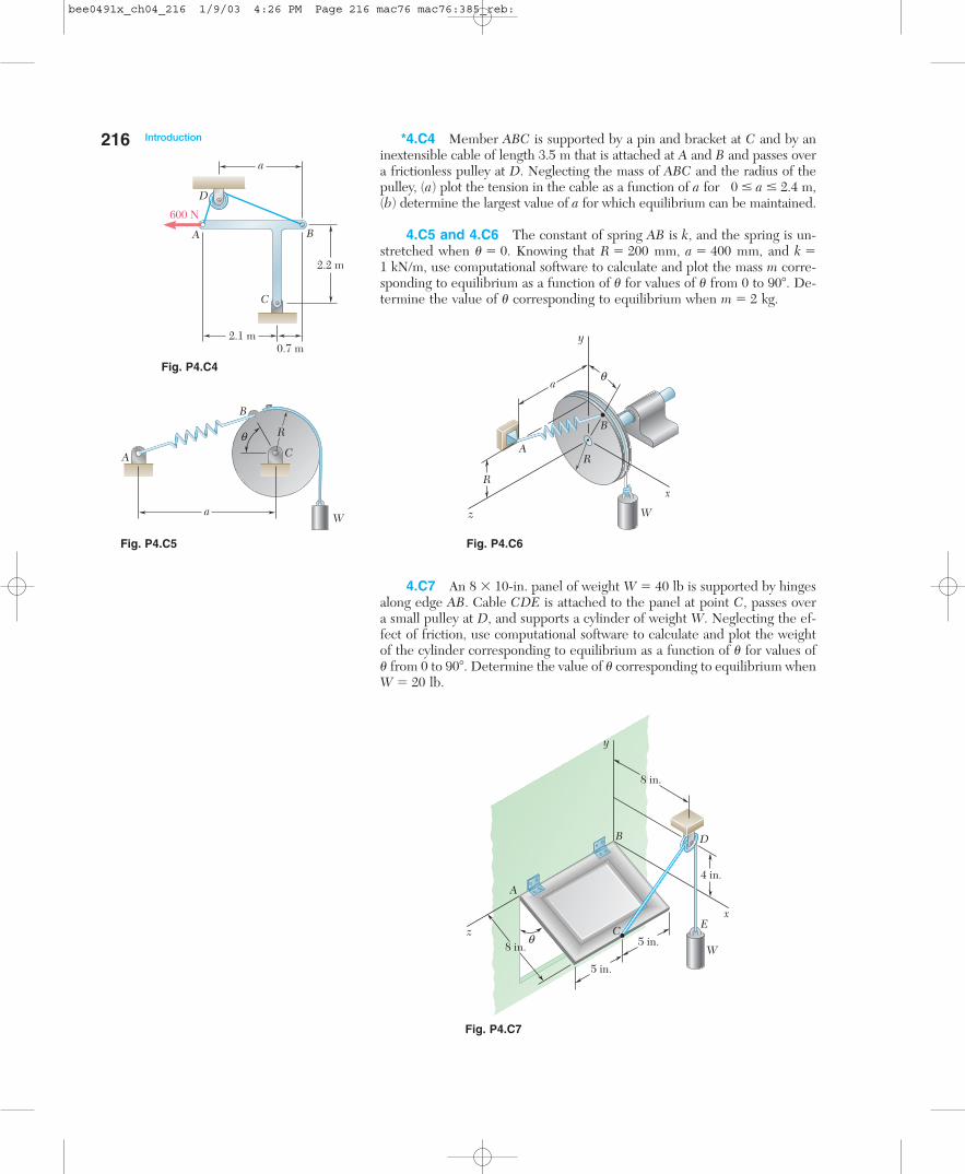
*4.C4 Member ABC is supported by a pin and bracket at C and by aninextensible cable of length 3.5 m that is attached at A and B and passes overa frictionless pulley at D. Neglecting the mass of ABC and the radius of thepulley, (a) plot the tension in the cable as a function of a for 0 � a � 2.4 m,(b) determine the largest value of a for which equilibrium can be maintained.
4.C5 and 4.C6 The constant of spring AB is k, and the spring is un-stretched when � � 0. Knowing that R � 200 mm, a � 400 mm, and k �1 kN/m, use computational software to calculate and plot the mass m corre-sponding to equilibrium as a function of � for values of � from 0 to 90�. De-termine the value of � corresponding to equilibrium when m � 2 kg.
216 Introduction
W
A
a
q
B
C
R
R
B
R
A
W
a
y
z
x
qFig. P4.C4
2.1 m
2.2 m
a
A
C
B
D
0.7 m
600 N
Fig. P4.C5 Fig. P4.C6
8 in.
8 in.
4 in.
5 in.
5 in.
A
B
C
D
Ez
x
y
qW
4.C7 An 8 � 10-in. panel of weight W � 40 lb is supported by hingesalong edge AB. Cable CDE is attached to the panel at point C, passes overa small pulley at D, and supports a cylinder of weight W. Neglecting the ef-fect of friction, use computational software to calculate and plot the weightof the cylinder corresponding to equilibrium as a function of � for values of� from 0 to 90�. Determine the value of � corresponding to equilibrium whenW � 20 lb.
Fig. P4.C7
bee0491x_ch04_216 1/9/03 4:26 PM Page 216 mac76 mac76:385_reb:
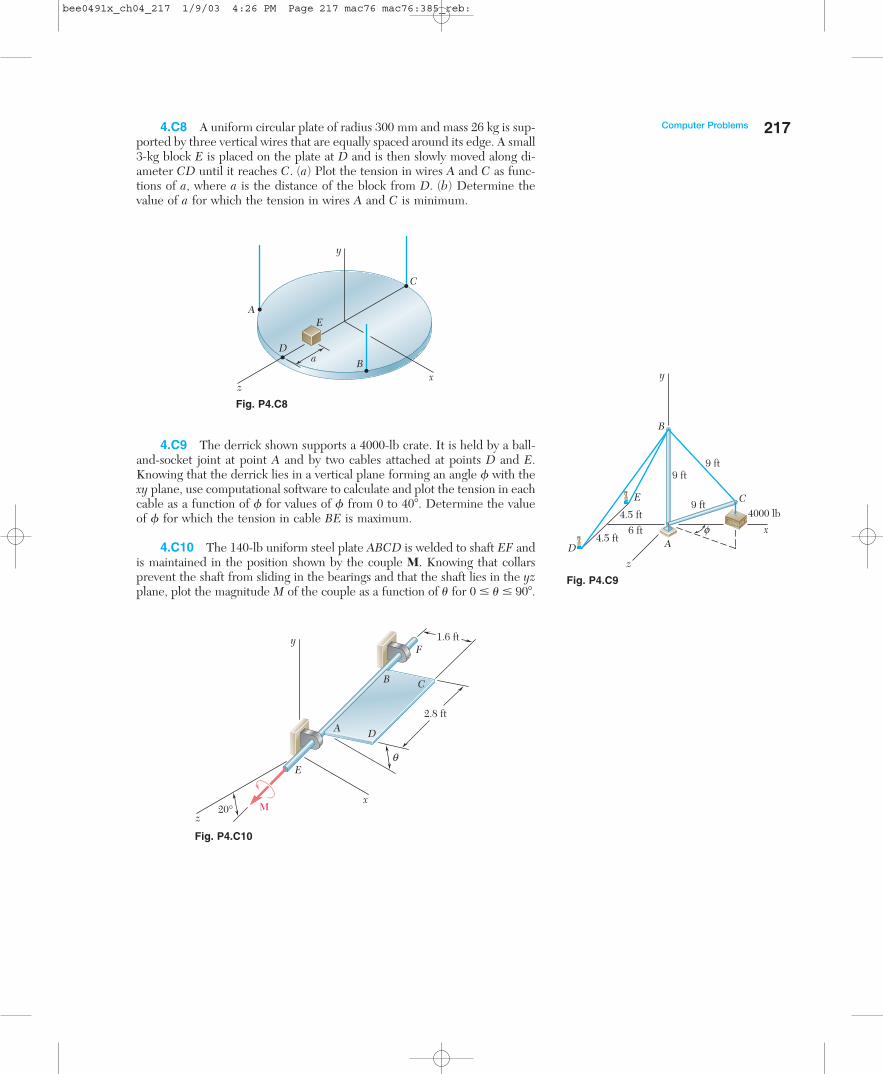
4.C8 A uniform circular plate of radius 300 mm and mass 26 kg is sup-ported by three vertical wires that are equally spaced around its edge. A small3-kg block E is placed on the plate at D and is then slowly moved along di-ameter CD until it reaches C. (a) Plot the tension in wires A and C as func-tions of a, where a is the distance of the block from D. (b) Determine thevalue of a for which the tension in wires A and C is minimum.
217Computer Problems
xz
E
B
A
C
Da
y
Fig. P4.C8
Fig. P4.C9
y
z
x
E
F
20°
2.8 ft
1.6 ft
M
B C
A D
q
Fig. P4.C10
4.C9 The derrick shown supports a 4000-lb crate. It is held by a ball-and-socket joint at point A and by two cables attached at points D and E.Knowing that the derrick lies in a vertical plane forming an angle � with thexy plane, use computational software to calculate and plot the tension in eachcable as a function of � for values of � from 0 to 40�. Determine the valueof � for which the tension in cable BE is maximum.
4.C10 The 140-lb uniform steel plate ABCD is welded to shaft EF andis maintained in the position shown by the couple M. Knowing that collarsprevent the shaft from sliding in the bearings and that the shaft lies in the yzplane, plot the magnitude M of the couple as a function of � for 0 � � � 90�.
y
x
z
B
E
D
C
Af
4000 lb
9 ft9 ft
9 ft
6 ft4.5 ft
4.5 ft
bee0491x_ch04_217 1/9/03 4:26 PM Page 217 mac76 mac76:385_reb:


