"w"---..-.-.-7----w .P,i... w-ca. ..i.-77-Y T. .15. 4. t0 -+ 4) 'EO 4) .0 4) Bell Laboratories Record 43. +. . Z 3 .+ i 4} Yo x 43 I .+ t c f} -+ 43' 'EO o c .. -Ei) c» 43. 43, 11 `fJ io -E0 t cs} .* 43' 4, -+ S} t, 4) t0 4) Ship-to-Shore Radio Receiver for use on -Ei> r the S.S. Leviathan -+ c» -+ 4} c, % 4} Volume VIII - Number 4 -+ 43. December ** +' Ig29 0 4} +. 34.)-4-4-4-4-4-4- r-4-4-44--t4-t4-4.4444-.4.4.r www.americanradiohistory.com
Transcript
"w"---..-.-.-7----w .P,i... w-ca. ..i.-77-Y T. .15. 4. t0
-+ 4) 'EO
4) .0 4) Bell Laboratories
Record 43.
+. . Z
3 .+ i 4} Yo x
43 I .+
t c f} -+ 43' 'EO
o c .. -Ei)
c» 43.
43, 11 `fJ io
-E0 t cs} .* 43'
4, -+ S} t, 4) t0 4) Ship-to-Shore Radio Receiver for use on -Ei>
Vice -President Gherardi Addresses the Laboratories' Supervisory Staff
ON November 8th, Bancroft Gherardi, Vice President of the American Telephone and
Telegraph Company and in charge of the Department of Operation and Engineering, in an inspiring address to the supervisory staff of the Labo- ratories, discussed the present posi- tion of the Bell System and its im- mediate prospects for even greater growth and a wider field of useful- ness. The growth of the business dur- ing the past few years and the esti- mated trend for the next half decade -both as indicated by number of sta- tions, growth of plant, or dollars of revenue, and as expressed in calling rates or variety of service -were brought out in detailed discussion and exhibited graphically by slides. The growth for the past five years has been very large but that predicted for the next like period is expected to far surpass all previous experience.
As a fitting preface to such a sur- vey, Mr. Gherardi quoted from the annual report to the stockholders of the American Telephone and Tele- graph Company for 1927, in which President Gifford had said: "The American Telephone and Telegraph Company accepts its responsibility for a nation -wide telephone service as a public trust. Its duty is to provide the American people with adequate, de- pendable, and satisfactory telephone service at a reasonable cost." In its effort to provide adequate facilities, the Bell System is making gross addi-
tions to plant at the rate of approxi- mately $500,000,000 a year. In the actual building of adequate plant the Laboratories plays no direct part but in making the service more dependable and more satisfactory, and in render- ing it at a lower cost, a great deal de- pends on the activities of these Labo- ratories. The fact that every work- ing day some two million dollars worth of plant is built emphasizes the importance of getting the improve- ments resulting from these activities completed and into the plant as rap- idly as possible.
Figures indicating the phenomenal growth of the Bell System may be taken from almost any branch of the service ; they are startlingly large. The net gain in number of stations has recently averaged well over 700,000 per year, and substantially greater gains are looked for during the five year period, so that by 1933 there will be- according to estimates - some eighteen and one -half million Bell stations in service as against about fourteen million at the end of 1928. Large upward trends also exist for the net additions to plant:- 1929 will represent an increase of nearly 40% over 1928, and still larger pro- grams are foreseen over the next five year period. During this period it is expected that growth in toll business. for example, will be equal to the en- tire business handled up to the year 1925. In other words, the growth for the next five years will be as much as
for the first forty -eight years of the System's existence. Greatest of all are the increases in the Long Lines Department. Based on circuit miles, the growth from 1923 to 1928 was over l00% and from 1928 to 1933 is expected to be 250%. These almost unbelievable figures are proof, if any were needed, that the telephone has become an essential part of our mod- ern life; that the immense value of a unified communication system to the social, business, and political life of the country is ever increasingly recog- nized.
That telephone service may be both dependable and satisfactory, it is not alone sufficient that the plant be ade- quate, but particular attention must be given to every phase of the service rendered. In considering service it is essential to think of it from the stand- point of all departments, and not sim- ply in its narrower sense relating to the completion of telephone connec- tions. Also the type of service taken by our subscribers should be consistent with the overall problem. For ex- ample, the highest grade of service is not compatible with too many multi- party lines, and the best efforts of the Bell System will fall short of the de- sired objectives if our subscribers are not induced to take the highest grade of service consistent with their re- quirements.
In connection with the general mat- ter of telephone service, Mr. Gherardi presented a picture of the possibilities of still further improvements ahead. In this connection, he reviewed the progress already made in the opera- tions of the Plant, Traffic, Commer- cial, and other departments and dis- cussed many of the interesting prob- lems on which these departments are working at the present time with a
view to still further advancements. Among the factors tending toward
improvement in service under the in- creasingly complicated operating con- ditions, Mr. Gherardi discussed the gradual substitution of the dial for manual operation. While this service naturally grew slowly at first, it is now increasing at a rapid rate, and by
1934 it is expected that more than one -half of the stations in the Bell System will be operated on a dial basis. He also referred to the inter- esting possibilities for improvement in service by the work going on in con- nection with private branch exchange operation, which has such a direct bearing on the whole telephone service problem. Reference was made to the important part which the Labora- tories will be called upon to play in connection with these and the many other improvements which were re- ferred to.
Among other interesting prospects for improved service brought out by Mr. Gherardi was the use of by -prod- uct facilities. Some are already in use but many more are visioned for the future. There is, of course, the leased - wire service that has been common for many years. In addition, there is the telephone- typewriter service, and the "time" service which had been given up as a war measure but has recently been resumed in many locations with considerable success. These are but a few of the many possibilities of by- product service; others are still in the experimental stage, and undoubtedly still others lie in the future, awaiting only a general recognition of the need and the most fitting methods of pro- viding for them.
An essential part of rendering sat- isfactory service is that it shall please our customers. Every contact should
leave in the subscriber's mind the im- pression, not only of adequacy and efficiency of the service, but that be- hind every effort is the desire of the telephone company to please him. The extent of the Bell System should be evident in the breadth and scope of the facilities it offers, but in the con-
tacts with subscribers there should be a personal note of individual interest and of ever increasing readiness to serve. The importance of the will to please cannot be overestimated; the best interests of both the Bell System and the subscriber lie in the recog- nition of mutual interest.
cao oa Communication Progress eYymbolized
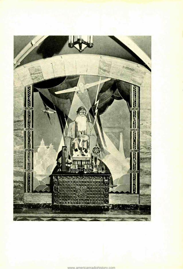
A striking feature in the entrance lobbies of the new Telephone Building in Denver is the series of mural paintings symbolizing the progress of communication. Two Indians send signals with a blanket and a smoky fire; a pony- express rider swings into his saddle; a line crew is at work in the Rockies; while a cable gang guides a cable into a manhole. "The Crucible of Science," reproduced on the oppo- site page, is of particular interest to us for its symbolization of our work and because these Laboratories were a source of the artist's inspiration. Allen True, who painted all the murals, was our guest for a day while he was planning his work. Readers of BELL LABO- RATORIES RECORD will recognize the border of the picture as similar to that of the panel on the front cover of the RECORD -a series of circuit symbols. Holding a replica of Bell's first telephone -a familiar object in our Historical Museum -the alchemist produces with his wand a dial hand -set from his flaming crucible. The owl, the hourglass and the retort -symbols of the past -are balanced by the microscope, the vacuum tube and the loudspeaker. At the top of his composition, Mr. True shows a Ford monoplane -pres- age, no doubt, of the recent purchase by the Laboratories.
The border design of telephone symbols has itself an interest- ing bit of history. When BELL LABORATORIES RECORD was being planned, an artist noted for pen- and -ink technique was sought for the cover design. Fownd in the person of Thomas M. Cleland, he was invited to visit the Laboratories that he might absorb some of the atmosphere of our organization. It was stipulated that the design need not contain any direct reference to the character of our business, but that it would be highly desirable to include unob- trusive features which could be recognized as peculiar to our work in the development of communication apparatus. One suggestion was the use of symbols of circuit emblems, and a border of this sort was designed for the central panel.
Taking Chances in Inspection -by- Sampling By H. F. DODGE Inspection Engineering
PPARATUS and equipment en- tering the Bell System plant has its quality safeguarded by
inspection at every step of production and at the completion of production as well. The major role of inspection is that of a detective whose business is to detect the existence of irregu- larities that affect quality, to follow up clues given by inspection data or other information that will lead to the discovery of either human or me- chanical causes of trouble, and -in cooperation with proper authorities - to remove them. Inspection con- ducted in the regular course of pro- duction is, however, not supposed to be carried on in a stand -offish way, waiting for serious troubles to occur before taking action with a club, but instead to detect trends in undesirable or costly directions before they go too far, and to whisper friendly counsel in the ears of those who may subse- quently be held to task if the erring tendencies are unchecked.
Neglecting possible errors in in- spection itself, one hundred per cent conformance with certain require- ments may be insured by one hundred per cent inspection. Every loading coil manufactured, for example, can be measured on a test set and if neces- sary adjusted to give an inductance value within prescribed limits. The satisfactoriness of product in respect to some requirements, on the other hand, can only be determined by tak- ing a sample. Thus the tensile strength
of a shipment of nickel -silver sheet, used in making relay springs, can be estimated only by taking a number of sample strips and testing them. As quality is a variable, these samples will exhibit differences among them- selves, and it can only be hoped that by taking a large enough number of samples the group of measurements may be assumed to represent faith- fully the quality of the entire ship- ment. Or again, heat coils can be measured for their "time of blow- ing" only by destroying a sample. In such cases, where inspection itself is destructive, complete inspection is ob- viously out of the question.
When inspection is not destructive, the product may be inspected either completely or by sampling. There are many places in the intermediate stages of production where sampling is resorted to as a matter of economy, providing it is consistent with the re- quirements for final quality. It is sel- dom economical to produce material which conforms one hundred per cent with all requirements. In many of the internal stages it may cost less, all things considered, to turn out ma- terial in which a large majority of the pieces fall within the engineering re- quirements, and then to depend on inspection or subsequent assembly steps to weed out the few slightly de- fective ones. How much defective material can economically be passed along, depends on the relative costs of weeding out defects by two differ-
ent methods; by inspection on the one hand and during subsequent assembly or installation processes on the other. If the average percentage of defec- tives turned out in one of the earlier stages of production is held quite low, the segregation of the defective pieces can often be done most economically by the operatives in the subsequent processing stage, and the intermedi- ate inspection can be conducted on a sampling basis to eliminate any lots of distinctly subnormal quality.
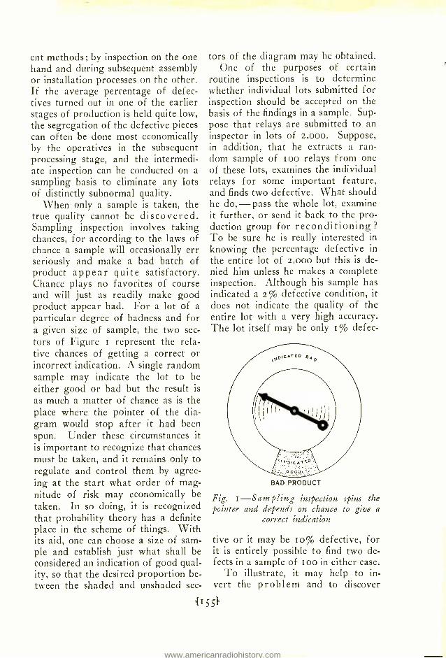
When only a sample is taken, the true quality cannot be discovered. Sampling inspection involves taking chances, for according to the laws of chance a sample will occasionally err seriously and make a bad batch of product appear quite satisfactory. Chance plays no favorites of course and will just as readily make good product appear bad. For a lot of a particular degree of badness and for a given size of sample, the two sec- tors of Figure i represent the rela- tive chances of getting a correct or incorrect indication. A single random sample may indicate the lot to be either good or bad but the result is
as much a matter of chance as is the place where the pointer of the dia- gram would stop after it had been spun. Under these circumstances it is important to recognize that chances must be taken, and it remains only to regulate and control them by agree- ing at the start what order of mag- nitude of risk may economically be taken. In so doing, it is recognized that probability theory has a definite place in the scheme of things. With its aid, one can choose a size of sam- ple and establish just what shall be considered an indication of good qual- ity, so that the desired proportion be- tween the shaded and unshaded sec-
tors of the diagram may be obtained. One of the purposes of certain
routine inspections is to determine whether individual lots submitted for inspection should be accepted on the basis of the findings in a sample. Sup- pose that relays are submitted to an inspector in lots of 2,000. Suppose, in addition, that he extracts a ran- dom sample of i oo relays from one of these lots, examines the individual relays for some important feature, and finds two defective. What should he do, -pass the whole lot, examine it further, or send it back to the pro- duction group for reconditioning? To be sure he is really interested in knowing the percentage defective in
the entire lot of 2,000 but this is de- nied him unless he makes a complete inspection. Although his sample has indicated a 2% defective condition, it does not indicate the quality of the entire lot with a very high accuracy. The lot itself may be only I% defec-
\OICATEO 840
BAD PRODUCT
Fig. 1-Sampling inspection spins the pointer and depends on chance to give a
correct indication
tive or it may be Io% defective, for it is entirely possible to find two de- fects in a sample of Loo in either case.
To illustrate, it may help to in- vert the problem and to discover
what the indications may be in sam- ples drawn from a lot which is defi- nitely known to contain i % of de- fective relays. If a number of inde- pendent random samples of roo re- lays each were to be taken from this
40
30
20
o
o
1 °/e DEFECTIVE LOT
O 1 2 3 4 5 IÓ 1'5' 20
5 i DEFECTIVE LOT
O 1 2 3 4
OF
0 - .-- r-- -- O 1 2 3 4 5
NUMBER
10 15
10 DEFECTIVE LOT
20
10 15 20 OF DEFECTS I N SAMPLE
Fig. 2- Distribution of number of de- fects expected in random samples of roo pieces drawn from lots of different quality
lot, theory shows that one might ex- pect to find no defects whatever in 37% of them, exactly one defect in another 37% of them, two defects in 18% of them, and so on as shown in the upper diagram of Figure 2. In like manner, the middle and bottom diagrams show the expected percent- age of samples of roo relays each that would show various percentages of defects if drawn from a 5% and from a ro% defective lot respectively.
Now what is the chance of accept- ing lots of these various degrees of defectiveness that are submitted? Suppose the instructions were to ac- cept any lot if the sample drawn from it contained two or less defects. The diagrams of Figure 2 indicate that in a sampling experiment an inspector
would expect to find two or less de- fects in 92% of the samples from a
lot containing r % of defective pieces, in 12% of the samples from a lot containing 5% of defective pieces, and in 0.3% of the samples from a
lot containing 10% of defective pieces. Expressed in another way, the chances of accepting any 1% defec- tive lot submitted to him are 92 in roo. In like manner, the chances of accepting a 5% defective lot are about one in eight, and the chances of ac-
cepting a lot io% defective are only three in a thousand. This is illus- trated in Figure 3 for a submitted lot having 5% of defective pieces. Here the sizes of the sectors corre- spond exactly to the heights of the rectangles in the middle diagram of Figure 2, and represent the probabil- ity of finding various numbers of de- fects in a sample of roo pieces.
This is a use of probability theory which is employed quite widely in set- ting up sampling schemes to deter- mine the acceptability of product. It provides a basis whereby the planning organization may select criteria of acceptance so as to fix the chances of accepting submitted product of any
Fig. 3- Sector "A" represents a r -in -8 chance of accepting a 5% defective lot
tension of the use of probabilities makes it possible to establish an in-
spection routine which involves a min- imum of inspection cost for a risk of acceptable magnitude.
Although a consid- erable amount of in-
spection work involves comparing magnitudes with some engineering requirement and mak- ing records of the percentage of failures to meet that require- ment, there are many places where the ac-
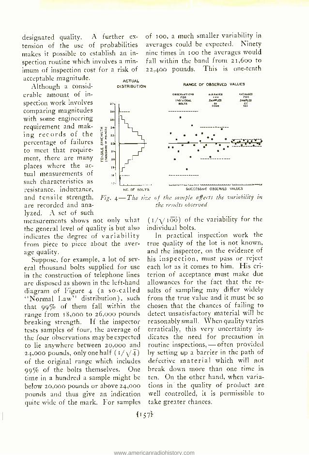
tual measurements of such characteristics as resistance, inductance, and tensile strength, are recorded and ana- lyzed. A set of such measurements shows not only what the general level of quality is but also indicates the degree of variability from piece to piece about the aver- age quality.
Suppose, for example, a lot of sev- eral thousand bolts supplied for use in the construction of telephone lines are disposed as shown in the left -hand diagram of Figure 4 (a so- called "Normal Law" distribution), such that 99% of them fall within the range from t 8,000 to 26,000 pounds breaking strength. If the inspector tests samples of four, the average of the four observations may be expected to lie anywhere between 20,000 and 24,000 pounds, only one half (t /-y 4 ) of the original range which includes 99% of the bolts themselves. One time in a hundred a sample might be below 20,000 pounds or above 24,000 pounds and thus give an indication quite wide of the mark. For samples
27
28
25
2
I.
la
17
of ioo, a much smaller variability in
averages could be expected. Ninety nine times in too the averages would fall within the band from 21,60o to 22,400 pounds. This is one -tenth
ACTUAL DISTRIBUTION
NO. OF BOLTS
Fig. 4-The size
RANGE OF OBSERVED VALUES
OBSERVATIONS FOR
INDIVIDUAL BOLTS
AVERAGES FOR
SAMPLES OF
FOUR
.. AVERAGES
FOR
SAMPLES
1ÓÓ
.-..- .' . - -. B___
.
SUCCESSIVE OBSERVED VALUES
of the sample affects the variability the results observed
in
( too) of the variability for the individual bolts.
In practical inspection work the true quality of the lot is not known, and the inspector, on the evidence of his inspection, must pass or reject each lot as it comes to him. His cri- terion of acceptance must make due allowances for the fact that the re- sults of sampling may differ widely from the true value and it must be so chosen that the chances of failing to detect unsatisfactory material will be reasonably small. When quality varies erratically, this very uncertainty in- dicates the need for precaution in routine inspections, - often provided by setting up a barrier in the path of defective material which will not break down more than one time in
ten. On the other hand, when varia- tions in the quality of product are well controlled, it is permissible to take greater chances.
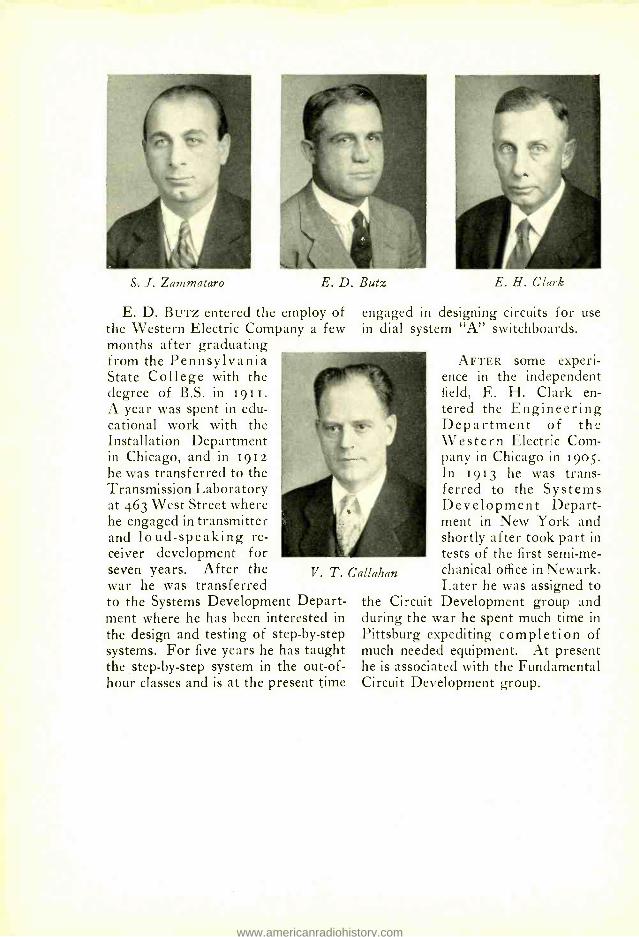
A New Emergency Power Supply Unit By V. T. CALLAHAN
Equipment Development
RESERVE power supply units for telephone and telegraph power plants have been stand-
ardized to secure uniformity in de- sign, and even though there are large differences in load in the various plants, four types of reserve units using six sizes of engines have been found adequate. Some form of inter- nal combustion engine is used as the prime mover in all of the standard plants. In the smaller plants these engines drive directly the battery - charging generators; for the larger offices it has been found more satis- factory, however, to have the engine drive an alternator which supplies current to drive motor -generator sets, or other converting apparatus. The three smaller types of engines have al-
COOLING WATER THERMOMETERS
COMBUSTION CHAMBER
PISTON
INLET VALVE
EXHAUST MANIFOLD COOLING WATER OVERFLOW
ready been described in the RECORD* and the series has now been completed by large units using Buffalo type ATT vertical engines.
Although reliability is always the principal consideration, different fac- tors have greater or less influence on the design depending on the size of the plant. With the newly developed engine which drives an alternator rated at 15o kilovolt -amperes, effi- ciency is of much more importance than it has been with the smaller sets.
The fuel used is, of course, an im- portant matter. Formerly the engines used in the larger offices ran on illu- minating gas, either natural or arti- ficial; in some cases the units were de- signed for either gas or gasoline. Be- cause of the different qualities of the
illuminating gases used in different parts of the country, it was eco- nomically impossible to design engines which would be equally effi- cient in all locations. In designing the new reserve plant, there- fore, it was decided to arrange it, as in the case of the types R and BA engines, for the use of gasoline exclusively. Final tests may then be made before shipment
CYUNDER HEAD COOLING WATER OVERFLOW
SPARK PLUG COMPRESSION TEST PLUG
GASOUNE PRIMING HOLE PIPED TO HAND
EXHAUST MANIFOLD
MODIFIED RICARDO CYLINDER HEAD
WATER JACKET
INLET MANIFOLD
HOT SPOT
HOLE FOR OILING VALVE STEMS PIPED TO THE HIGH PRESSURE OILING SYSTEM THROUGH A CONTROL VALVE
VALVE SPRING
PISTON RING
CYLINDER
PISTON AND CYLINDER LUBRICATING OL HOLE PIPED TOHPAND OIL
PISTON OR WRIST PIN
SLOT TO DIVERT HEAT FROM PISTON PIN BEARING
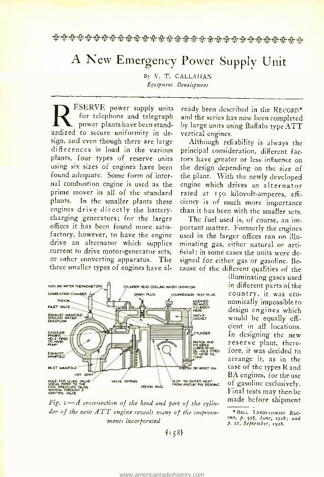
Fig. 1 -fl cross -section of the head and part of the cylin- der of the new 11 TT engine reveals many of the improve -
ments incorporated
{158}
' BELL LABORATORIES REC- ORD, p. 318, June, 1928; and p. 21, September, 1928.
with assurance that the results can be duplicated since the quality of gaso- line throughout the country is fairly uniform.
The ATT engine has an L head of a modified Ricardo type which main- tains the turbulence of the gas, set up as it en- ters the inlet valve, until ignition takes place. This is import- ant because the rate of combustion depends on the turbulence. Rapid combustion is aided also by locating the spark plugs near the center of the firing chambers which gives the shortest possible distance of flame trav- el. With a stagnant mixture at the time of ignition the flame prop- agation would be slow and a large part of the mixture would not be burned by the time the exhaust valve opened. This would result in the formation of carbon, burning of the exhaust valves, and a decreased efficiency.
With the larger engines, vibration also required more attention. To re- duce it to a minimum a large and ac-
curately balanced fly -wheel of the disk type is used, and its large mass smooths out the effect of the torque impulses. To reduce further the vi- bration, by decreasing the weight of the reciprocating parts, aluminum al- loy pistons are used. An oversize cam shaft is employed to permit the use of heavier valve springs, thereby re- ducing the possibility of spring break- age, and it was found that this, too, contributed considerably to quiet op- eration. It was found that mounting the entire sub -base on the floor on
RING GEAR ON FLYWHEEL
FLTWIfEL A
springs as done with some of the smaller sets was not satisfactory with the larger weight of the ATT engine. To make sure, however, that any vi- bration that may exist will not be transmitted to the building, the con-
SPRNG FOR RET RNING SNATCH AND GEMS TO NYE- POSITIONS
STARTNG MOTOR SWITCH AND GEM SHIFT HANDLE
OVERRUNNING CLUTCH GEAR
PIVOT
ROO FOR ACTUATING STARTING MOTOR SWITCH
KNURLED NANCoNNEEL TO ROTATE GEAR TO MEEN WITH RING GEAR ON FLYWHEEL EEFd1E ETARTNG
SLEEVE
STARTNG MOTOR
OVERRUNNING. CLUTCH GEAR
ROLLER
PMI
ERING
MUM ONVEN LIMBER Of OVERMJraaJG
SECTION A-A
NOTE: MECIMNEM SHOWN IN STARTING POSITION
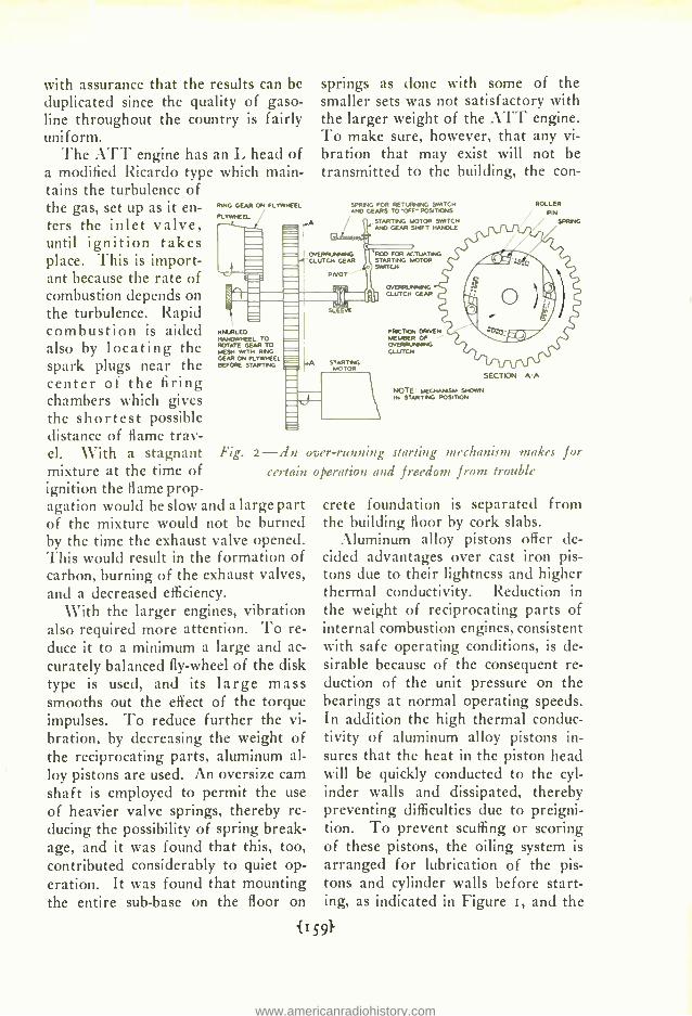
Fig. 2 -fln over -running starting mechanism makes for certain operation and freedom front trouble
crete foundation is separated from the building floor by cork slabs.
Aluminum alloy pistons offer de- cided advantages over cast iron pis- tons due to their lightness and higher thermal conductivity. Reduction in the weight of reciprocating parts of internal combustion engines, consistent with safe operating conditions, is de- sirable because of the consequent re- duction of the unit pressure on the bearings at normal operating speeds. In addition the high thermal conduc- tivity of aluminum alloy pistons in- sures that the heat in the piston head will be quickly conducted to the cyl- inder walls and dissipated, thereby preventing difficulties due to preigni- tion. To prevent scuffing or scoring of these pistons, the oiling system is arranged for lubrication of the pis- tons and cylinder walls before start- ing, as indicated in Figure i, and the
gasoline system was changed so that a small amount of gasoline may be in- jected into the intake manifold just before turning the engine over. These two changes insure that the pistons are properly lubricated and that excessive
which occasionally occurs with Bendix drives on larger engines, will not oc- cur. The starting motor switch han- dle when pulled part way to the right meshes the gears as shown and when pulled further to the right, closes the
circuit to the starting motor, turning the en-
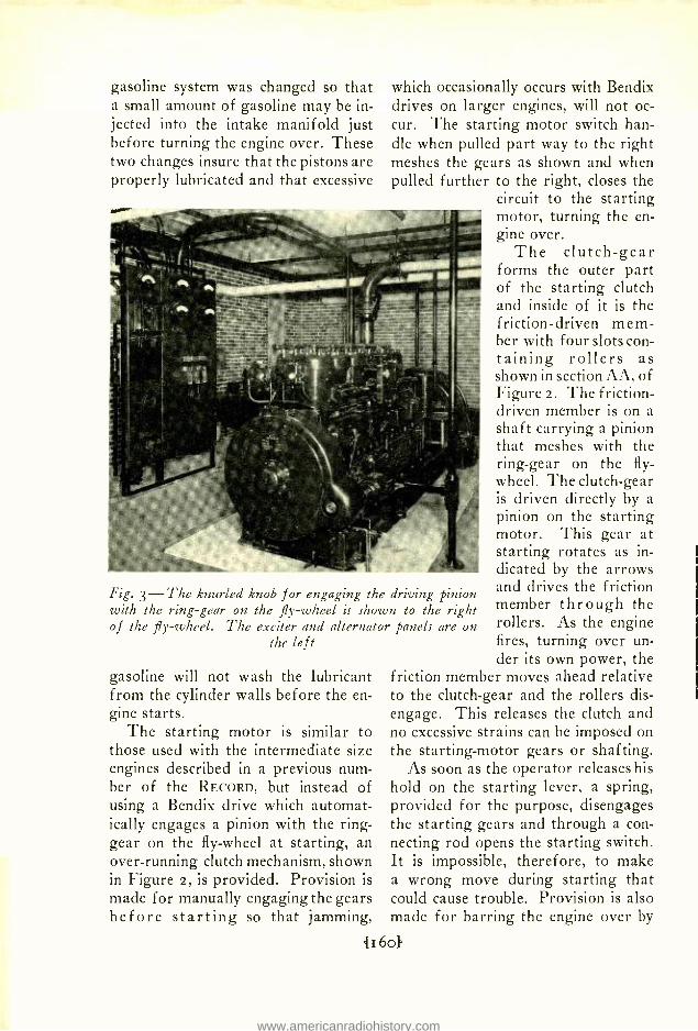
Fig. 3 -The knurled knob for engaging the driving pinion with the ring -gear on the fly -wheel is shown to the right of the fly- wheel. The exciter and alternator panels are on
the le f t
gasoline will not wash the lubricant from the cylinder walls before the en- gine starts.
The starting motor is similar to those used with the intermediate size engines described in a previous num- ber of the RECORD, but instead of using a Bendix drive which automat- ically engages a pinion with the ring - gear on the fly -wheel at starting, an over -running clutch mechanism, shown in Figure 2, is provided. Provision is
made for manually engaging the gears before starting so that jamming,
gine over. The clutch -gear
forms the outer part of the starting clutch and inside of it is the friction - driven mem- ber with four slots con- taining rollers as shown in section AA, of Figure 2. The f riction- driven member is on a shaft carrying a pinion that meshes with the ring -gear on the fly- wheel. The clutch -gear is driven directly by a pinion on the starting motor. This gear at starting rotates as in- dicated by the arrows and drives the friction member through the rollers. As the engine fires, turning over un- der its own power, the
friction member moves ahead relative to the clutch -gear and the rollers dis- engage. This releases the clutch and no excessive strains can be imposed on the starting -motor gears or shafting.
As soon as the operator releases his hold on the starting lever, a spring, provided for the purpose, disengages the starting gears and through a con- necting rod opens the starting switch. It is impossible, therefore, to make a wrong move during starting that could cause trouble. Provision is also made for barring the engine over by
The control equipment for the en- gine is mounted on it but the alter- nator and exciter panels are mounted separately as shown in Figure 3. Here the voltage regulator and suitable me- ters and switches are conveniently arranged.
Duplicate high tension magnetos are provided, and an overspeed trip device grounds the ignition to stop the engine in case of excessive speed. The main gasoline supply is in a tank buried beneath the floor or in some
other safe location and a fuel pump, mounted on and driven by the engine, lifts the fuel to a small auxiliary reser- voir on the engine. A centrifugal gov- ernor maintains a speed regulation of five per cent from no load to full load. City water is used for cooling.
With the development of this ATT engine a range of power plants is com- pleted for all sizes of central offices. Safety and reliability have been the keynote in the design of all of them to insure that at no time will tele- phone service be curtailed because of lack of power.
Income and Expense Record
Booklets for personal income and expense record will again be distributed in all departments this year. Members of the Labo- ratories who signed the blank in last year's booklet will receive the 1930 edition through the company mail some time during December. Those who have not signed these blanks and wish to receive the books should notify their immediate super- visors or call Employee Service. As the result of suggestions offered by past users, numerous improvements have been incor-
i i i i + v + W + + + Wi W Lacquering and Plating in the Laboratories
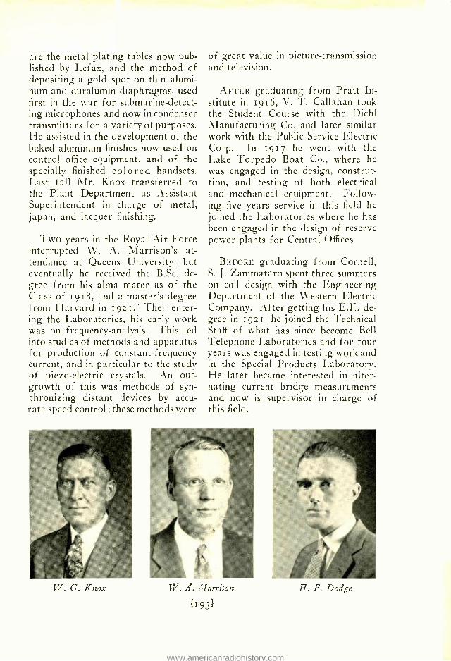
By W. G. KNOX Assistant Plant Superintendent
THE importance of the finish of metals in the telephone plant is apparent from the
extent to which it is found. Affecting both appearance and function, finish of one or another sort is almost uni- versally applied to metal telephone apparatus. Materials for finishing purposes are investigated, sometimes developed, and specified to the West- ern Electric Company, by these Labo- ratories.
To meet the needs of the Labora- tories for finishes which would be the equal of those produced by the Manu- facturing Department at Hawthorne, and for a means of applying special metal coatings to models of new tele- phone apparatus and equipment con-
BENCH
C HE MICA CONI ROI
JAPAN OVEN
SPRAY BOOTH DRYING
RACK
CRYSTAL OVEN
[CAB
BENCH
DRYING ROOM
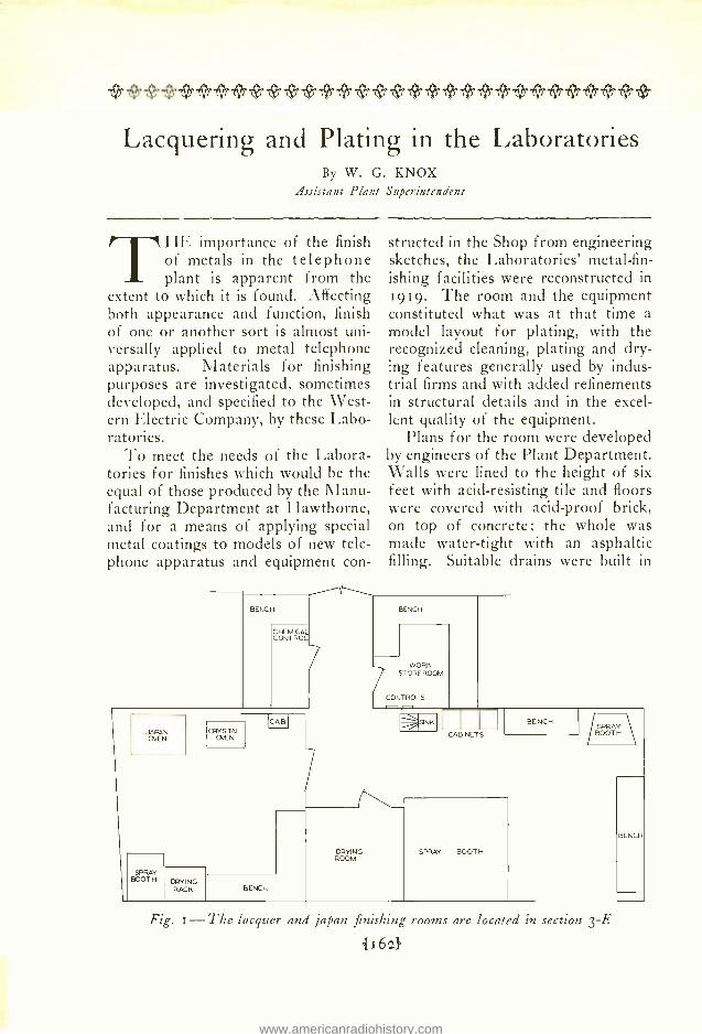
structed in the Shop from engineering sketches, the Laboratories' metal -fin- ishing facilities were reconstructed in 1919. The room and the equipment constituted what was at that time a
model layout for plating, with the recognized cleaning, plating and dry- ing features generally used by indus- trial firms and with added refinements in structural details and in the excel- lent quality of the equipment.
Plans for the room were developed by engineers of the Plant Department. Walls were lined to the height of six feet with acid- resisting tile and floors were covered with acid -proof brick, on top of concrete; the whole was made water -tight with an asphaltic filling. Suitable drains were built in
BENCH
WORK STOREROOM
CONTROLS
SINK
CABINETS
BENCH
SPRAY BOOTH
SPRAY BOOTH \
BENCH
Fig. i -The lacquer and japan finishing rooms are located in section 3 -E
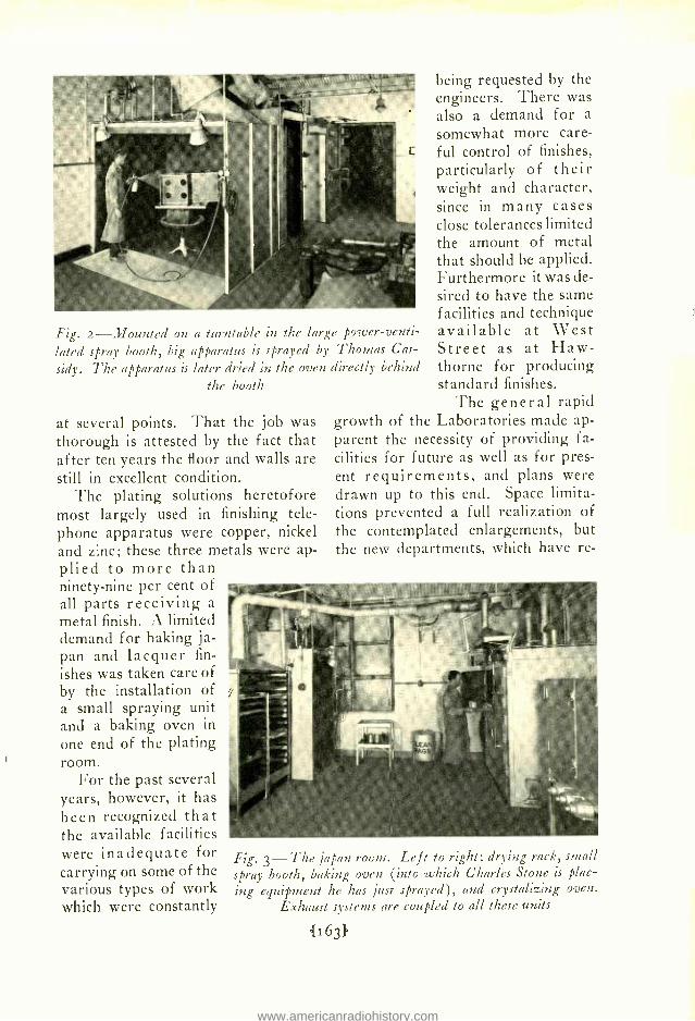
Fig. 2- Mounted on a turntable in the large power- venti-
lated spray booth, big apparatus is sprayed by Thomas Cas-
sidy. The apparatus is later dried in the oven directly behind the booth
at several points. That the job was thorough is attested by the fact that after ten years the floor and walls are still in excellent condition.
The plating solutions heretofore most largely used in finishing tele- phone apparatus were copper, nickel and zinc; these three metals were ap- plied to more than ninety -nine per cent of all parts receiving a
metal finish. A limited demand for baking ja- pan and lacquer fin-
ishes was taken care of by the installation of a small spraying unit and a baking oven in
one end of the plating room.
For the past several years, however, it has been recognized that the available facilities were inadequate for carrying on some of the various types of work which were constantly
being requested by the engineers. There was also a demand for a
somewhat more care- ful control of finishes, particularly of their weight and character, since in many cases close tolerances limited the amount of metal that should be applied. Furthermore it was de- sired to have the same facilities and technique available at West Street as at Haw- thorne for producing standard finishes.
The general rapid growth of the Laboratories made ap- parent the necessity of providing fa- cilities for future as well as for pres- ent requirements, and plans were drawn up to this end. Space limita- tions prevented a full realization of the contemplated enlargements, but the new departments, which have re-
Fig. 3 -The japan room. Left to right: drying rack, small spray booth, baking oven (into which Charles Stone is plac- ing equipment he has just sprayed), and crystalizing oven.
cently been completed, are expected to take care of the requirements for some time to come. The new Finishing De- partment is divided into two main sec- tions; one is used for the application of japans, lacquers, paints, varnishes and enamels, and the other for metal plating, facilitating a considerably in- creased diversity and refinement of finishing.
The japan and lacquer section is lo- cated on the third floor, in section "E," and is divided into two large rooms with a fire wall between them. Of two more small adjoining rooms, one is used to take care of all incom- ing work and finished outgoing work, and the other for a laboratory where chemical control analyses are made.
In one of the large rooms, used for the application and baking of japan and varnish coatings, there is a three - by- three -by -seven foot DeVilbiss spray booth, with a direct exhaust system re- moving spray fumes at the rate of about i000 cubic feet per minute. Next to this booth is a steam -heated drying oven which is used for semi-
drying the freshly applied films. There are also two electrically heated ovens for baking japan and crystalline varnish or lacquer films. The three ovens are connected with a small cen- tral blower which removes the fumes from these units at a gentle rate, thus preventing the accumulation of exces- sive amounts of volatile solvents. Metal containers with self -closing doors are used for storing cans of paint and lacquer materials; safety cans contain solvent thinners and cleaning solutions. Ample bench space assists the operator to handle all in- coming apparatus.
In the adjoining room, somewhat larger in size and used mainly for lac- quer spraying, there are two spray booths, eight -by- seven -by -seven and three -by- three -by -two feet. The larger is equipped with an indirect exhaust system of the latest type : an outlet flue, free of fans and motor shafts, re- moving about s000 cubic feet of air per minute. This booth meets a long - felt need by enabling the operator to spray very large apparatus and frame-
DES
BENCH
OVEN
SAWDUST MOTI
HOT
COLO
icoLoi
[SILVER
IBRAssI
NICHEL [HOT
COPPER MOT1
CLEANSING BATHS
ZINC k
MOTOR-GEN.
HOT COLO COLD CHIC/MUM
IFqTI
A B C D E 1
CD C
ZINC 1H00
CHXMNM IF10TI
THERMOSTAT r,
BENCH
MOTOR-
GEN.
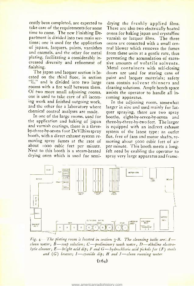
Fig. 4 -The plating room is located in section 3 -B. The cleansing baths are: il - clean water; B -soap solution; C- preliminary wash water; D- alkaline electro- lytic cleaner; E- bright acid dip; F and G- hydrochloric acid pickets for (F) steels
and (G) brasses; I- cyanide dip; H and J -clean running water
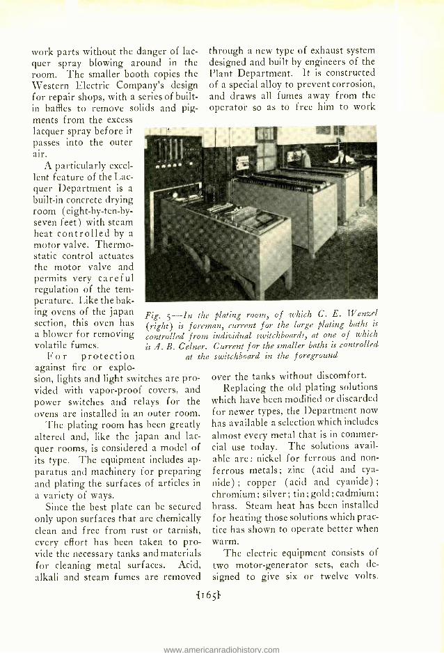
work parts without the danger of lac- quer spray blowing around in the room. The smaller booth copies the Western Electric Company's design for repair shops, with a series of built - in baffles to remove solids and pig- ments from the excess lacquer spray before it passes into the outer air.
A particularly excel- lent feature of the Lac- quer Department is a
built -in concrete drying room (eight-by- ten -by- seven feet) with steam heat controlled by a motor valve. Thermo- static control actuates the motor valve and permits very careful regulation of the tem- perature. Like the bak- ing ovens of the japan section, this oven has a blower for removing volatile fumes.
For protection against fire or explo- sion, lights and light switches are pro- vided with vapor -proof covers, and power switches and relays for the ovens are installed in an outer room.
The plating room has been greatly altered and, like the japan and lac- quer rooms, is considered a model of its type. The equipment includes ap- paratus and machinery for preparing and plating the surfaces of articles in a variety of ways.
Since the best plate can be secured only upon surfaces that are chemically clean and free from rust or tarnish, every effort has been taken to pro- vide the necessary tanks and materials for cleaning metal surfaces. Acid, alkali and steam fumes are removed
through a new type of exhaust system designed and built by engineers of the Plant Department. It is constructed of a special alloy to prevent corrosion, and draws all fumes away from the operator so as to free him to work
Fig. 5 -In the plating room, of which C. E. Wenzel (right) is foreman, current for the large plating baths is
controlled from individual switchboards, at one of which
is A. B. Celner. Current for the smaller baths is controlled at the switchboard in the foreground
over the tanks without discomfort. Replacing the old plating solutions
which have been modified or discarded for newer types, the Department now has available a selection which includes
almost every metal that is in commer- cial use today. The solutions avail- able are: nickel for ferrous and non- ferrous metals; zinc (acid and cya-
nide) ; copper (acid and cyanide) ;
chromium; silver; tin; gold; cadmium; brass. Steam heat has been installed for heating those solutions which prac- tice has shown to operate better when warm.
The electric equipment consists of two motor -generator sets, each de- signed to give six or twelve volts.
One generator is rated at Soo amperes capacity and the other at 2000 am- peres capacity. The latter is used ex- clusively for chromium plating.
To keep the cleaning and plating solutions in good working condition, frequent chemical tests are made. In the case of the gold plating solution, for instance, which involves a high in-
good chromium deposit. For remov- ing the fumes generated during chro- mium plating operations considerable care has been used in designing an ex- haust hood which will be effective yet in no way interfere with the operator's access to the tank.
The magnitude and variety of work constantly passing through the new
Finishing Department is great : practically every unit is in con- stant use, and during many weekly periods about zo,000 parts are given a finish of one kind or another. In many cases the parts to be finished require two or three separate metal coatings and in other cases five or six coats of japan or lac- quer.
The Finishing De- partment cooperates with engineers of the Laboratories in apply- ing finishes to parts used in the assembly of special apparatus
and of finishes which are employed for comparative test purposes. Every care is used in applying special finishes in accordance with the wishes of the engineer or with standard practice. In producing many finishes, the data gathered from the work carried on by the Finishing Department has been useful as a basis for formulating specifications issued to the Manufac- turing Department or the Repair Shops of the Western Electric Com- pany.
Fig. 6- The large and small chromium baths are supplied with current from a special motor -generator out of the pic- ture to the left. lit the cleansing baths are W. Frees (left)
and P. Ferrarotto
vestment, tests for free sodium cyan- ide and for gold are made almost daily. This frequent testing is neces- sitated by the great quantity of work which is plated in a bath of such small proportions : sometimes as many as a thousand parts are plated weekly.
Chromium plating requires especial attention, - the temperature of the solution and the "current density" used for depositing the metal must be carefully controlled. Special "rack- ing" of parts also aids in securing a
WHEN Sir Charles Wheat- stone in 1843 devised the bridge method for compar-
ing resistances, he paved the way for the elaborate bridge family of today. The early bridges were used only for measuring resistances but it was nat- ural that investigators should employ the same principle to measure induc- tance and capacitance when the use of variable currents in electric circuits made these properties significant. Be- cause resistance, inductance, and ca- pacitance may be combined in various ways to form bridge networks, a large variety of circuits have been proposed for the measurement of impedance but only a few have proved worthy of careful refinement for precise measurements.
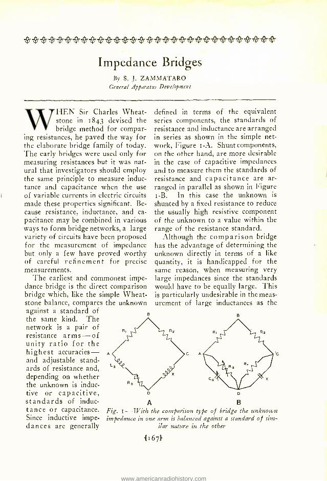
The earliest and commonest impe- dance bridge is the direct comparison bridge which, like the simple Wheat- stone balance, compares the unknown against a standard of the same kind. The network is a pair of resistance arms -of unity ratio for the highest accuracies - and adjustable stand- ards of resistance and, depending on whether the unknown is induc- tive or capacitive, standards of induc- tance or capacitance. Since inductive impe- dances are generally
defined in terms of the equivalent series components, the standards of resistance and inductance are arranged in series as shown in the simple net- work, Figure i -A. Shunt components, on the other hand, are more desirable in the case of capacitive impedances and to measure them the standards of resistance and capacitance are ar- ranged in parallel as shown in Figure i -B. In this case the unknown is
shunted by a fixed resistance to reduce the usually high resistive component of the unknown to a value within the range of the resistance standard.
Although the comparison bridge has the advantage of determining the unknown directly in terms of a like quantity, it is handicapped for the same reason, when measuring very large impedances since the standards would have to be equally large. This is particularly undesirable in the meas- urement of large inductances as the
B
D
A
Fig. i -With the comparison type of bridge the unknown impedance in one arm is balanced against a standard of sim-
required standards would be prohibi- tively unwieldy and expensive to main- tain in constant calibration.
To avoid this, large inductances are usually measured in terms of capaci- tance standards by means of the reso-
A Fig. 2 -With the resonance bridge the unknown induct- ance is resonated by an adjustable condenser in the arm with it, and the unknown resistance is balanced by a standard
resistance in the opposite arm
condensers, the only limitation to the maximum inductance being the degree of precision with which the smallest standard capacitance is known.
As the standard condenser and the unknown inductance are arranged in
series, this method is further qualified as the series resonance meth- od. When the ratio of the inductance to the resistance of the unknown impedance is small, however, it is preferable to arrange the standard condenser and the unknown im- pedance in parallel, as in Figure 2 -B. Then the method is known as the parallel resonance method. As with the comparison capacitance
bridge, a resistance is shunted across the unknown to reduce the resistive component to a measurable value.
Due to the fact that condenser standards are very stable and can be calibrated with greater precision than inductance standards at the higher frequencies the resonance bridge has
B
B
c
nance bridge. This method combines the Wheatstone principle with the principle of resonance. The bridge network, shown schematically in Fig- ure 2 -A, consists of a pair of equal ratio arms, an adjustable resistance standard in the standard arm and, in the opposite arm, an adjustable ca- pacitance standard in series with the unknown inductance. The bridge is balanced by adjusting the standard condenser and resistance until the re- actance of the condenser nullifies that of the inductance, leaving only a re- sistance in the unknown arm to be balanced by the standard resistance. The value of the unknown inductance is computed from the standard ca- pacitance setting and the frequency at which the balance is made by the fa- miliar resonance formula, ca2LC =i. It is evident from this relationship that very large inductances can be measured with correspondingly small
B
D
Fig. 3 -The Owen bridge has a skewed balance: a capacitance measures resistance,
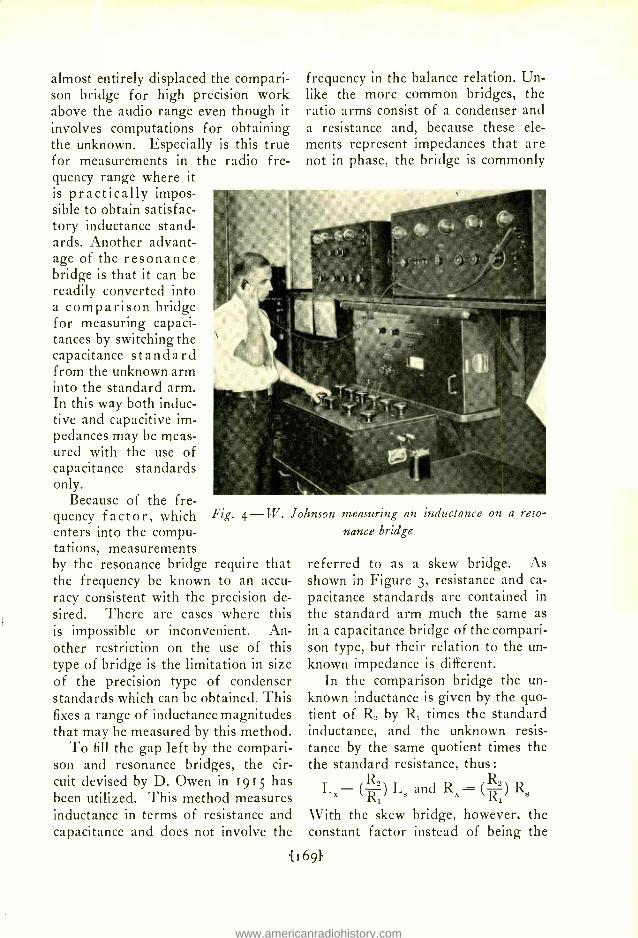
almost entirely displaced the compari- son bridge for high precision work above the audio range even though it involves computations for obtaining the unknown. Especially is this true for measurements in the radio fre- quency range where it is practically impos- sible to obtain satisfac- tory inductance stand- ards. Another advant- age of the resonance bridge is that it can be readily converted into a comparison bridge for measuring capaci- tances by switching the capacitance standard from the unknown arm into the standard arm. In this way both induc- tive and capacitive im- pedances may be meas- ured with the use of capacitance standards only.
Because of the fre- quency factor, which enters into the compu- tations, measurements by the resonance bridge require that the frequency be known to an accu- racy consistent with the precision de- sired. There are cases where this is impossible or inconvenient. An- other restriction on the use of this type of bridge is the limitation in size of the precision type of condenser standards which can be obtained. This fixes a range of inductance magnitudes that may be measured by this method.
To fill the gap left by the compari- son and resonance bridges, the cir- cuit devised by D. Owen in 1915 has been utilized. This method measures inductance in terms of resistance and capacitance and does not involve the
frequency in the balance relation. Un- like the more common bridges, the ratio arms consist of a condenser and a resistance and, because these ele- ments represent impedances that are not in phase, the bridge is commonly
Fig. 4 -W. Johnson measuring an
nance bridge inductance on a reso-
referred to as a skew bridge. As shown in Figure 3, resistance and ca- pacitance standards are contained in the standard arm much the same as in a capacitance bridge of the compari- son type, but their relation to the un- known impedance is different.
In the comparison bridge the un- known inductance is given by the quo- tient of Rz by R, times the standard inductance, and the unknown resis- tance by the same quotient times the the standard resistance, thus:
Lx= (R1) LM and RX= (Ri) RS
With the skew bridge, however, the constant factor instead of being the
quotient of the ratio arms is their product, and to obtain the unknown inductance this product is multiplied by the standard resistance, and to ob- tain the unknown resistance the prod- uct is divided by the standard ca- pacitance:
LX= (C1R2)RS and R.- (C1R 2)
It is this relationship -whereby a re- sistance measures the inductance com- ponent of the unknown and the capa- citance measures the resistance com- ponent -that constitutes the special peculiarity of the Owen bridge.
A suitable shielding scheme has been developed for the Owen bridge and the circuit has been sufficiently re- fined for use in the audio frequency
range with high precision. In one form of Owen bridge developed for shop testing, the constants have been so chosen that the bridge reads ef- fective resistance and inductance di- rectly and from its appearance could not be distinguished from an equiva- lent comparison bridge except that it is considerably smaller.
The comparison, resonance, and Owen bridges constitute the more im- portant types of bridges employed in the Laboratories and in the Manufac- turing Department of the Western Electric Company for testing impe- dances. The specific conditions of the tests determine which of these three types is most suitable for obtaining the desired measurements.
cao oe
r t.7&t Christmas
To those who like to look forward to the merriment of the next winter holiday season, the Employees' Savings Plan is sug- gested. A very small sum deposited regularly for you will grow to a surprisingly large amount by Christmas, 1930. The Financial Department will be glad to explain the details of
Evolution of the Call- Indicator System By E. H. CLARK
Loral System Development
IN changing from manual to dial operation there is usually a pe- riod, which in the larger cities
may be of considerable duration, dur- ing which both manual and dial offices will be in use. When this situation exists, calls are originated in an office of either type to be completed in one of the other. Among other things, therefore, equipment must be provided at the manual office to indicate to the operators the numbers dialed to their office for completion. Apparatus de- veloped to accomplish this -a group of numerals which light up to indicate the number wanted -is known as a
call indicator. The circuits and equip- ment used have, like the rest of the dial system, undergone a large amount of development since the first experi- mental call indicator was installed in the Cortlandt office in 1910.
The revertive puls- ing method, used for selecting numbers wanted in dial offices of the panel type and already described in the RECORD,* was also employed in the first call- indicator system. Power driven sequence switches at the manual office were utilized to return pulses to the subscriber's sender much as the selector
commutators do on calls completed in
a dial office. Six of these sequence switches, one for each of the possible digits and letters of a number called, constituted a complete register. The time required to completely record the number was about five seconds on the average. If but one such register were provided this recording time of five seconds would seriously affect the num- ber of calls that an operator could han- dle, so that several of them were fur- nished for each call -indicator position.
When a number had been complete- ly recorded on a register, the oper- ator was given an indication by the lighting of an assignment lamp asso- ciated with the plug of the trunk over which the call was coming, and the
* BELL LABORATORIES RECORD, June, 1929, P. 395.
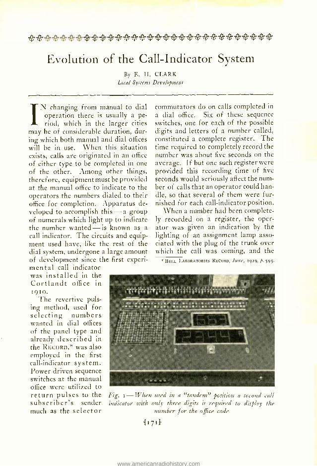
Fig. 1-117 hen used in a "tandem" position a second call indicator with only three digits is required to display the
number recorded was displayed on her indicator. The time required to trans- fer the record from the sequence switch to the call indicator was so short that there was no appreciable delay in operating. When the plug was inserted in the jack of the line
the operator receiving the numbers directly from the senders at the call- ing office.
This method is called the relay call- indicator system because only re- lays are used at the call- indicator posi- tions to record the number wanted.
The first plan devel- oped was based upon a system of ground re- turn pulses. This method was not adopt- ed however because of the disadvantage of the high potential that would be necessary to overcome earth poten- tials. A metallic sig- naling method was de- veloped instead which was capable of trans- mitting signals at the required speed.
Even with the faster method of pulsing, an overlapping method of operating was neces- sary to prevent a drag on the operator. With
this method an operator picks up the proper plug when the number is first displayed and then presses a display key for the next number. While she is inserting the plug into the desired line the next number is being dis- played. If no call were waiting, the insertion of her plug would extinguish the number displayed.
The call indicators used with the first system, installed in Cortlandt Office in 1910, and in Newark in 1914, made use of universal figures similar to the carriage call devices used in front of theatres, and for this reason were termed "carriage call -in- dicators". The arrangement is shown, installed in a keyshelf, in Figure i.
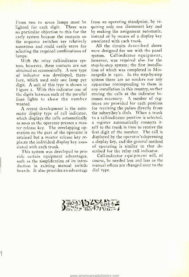
Fig. 2 -tiVith the call indicator of the relay type only a single lamp is lighted for each digit of the number called
called, the register would release and the number would disappear from the call indicator. Both the register and the call indicator were then ready for another call, and if one were waiting on another register, it would be im- mediately displayed on the call indi- cator.
Although this method was very sat- isfactory it required power driven equipment at the manual office, which it was desirable to eliminate. This is
accomplished by using relay registers which were operated by pulses trans- mitted by the sender. A faster puls- ing method was also developed which made it possible to use only one re- cording device for each call indicator,
From two to seven lamps must be lighted for each digit. There was no particular objection to this for the early system because the contacts on the sequence switches are relatively numerous and could easily serve for selecting the required combinations of lamps.
With the relay call- indicator sys- tem, however, these contacts are not obtained so economically. A new type of indicator was developed, there- fore, which used only one lamp per digit. A unit of this type is shown in Figure 2. With this indicator one of the digits between each of the parallel lines lights to show the number wanted.
A recent development is the auto- matic display type of call indicator, which displays the calls automatically as soon as the operator presses a mas- ter release key. The overlapping op- eration on the part of the operator is
retained but a master release key re- places the individual display key asso- ciated with each trunk.
This system was developed to pro- vide certain equipment advantages, such as the simplification of its intro- duction in existing manual switch- boards. It also provides an advantage
from an operating standpoint, by re- quiring only one disconnect key and by making the assignment automatic, instead of by means of a display key associated with each trunk.
All the circuits described above were designed for use with the panel system. Call- indicator equipment, however, was required also for the step -by -step system; the first installa- tion of which was completed in Min- neapolis in 192o. In the step -by -step system there are no senders nor any apparatus corresponding to them in
any installation in this country, so that storing the calls at the indicator be- comes necessary. A number of reg- isters are provided for each position for receiving the pulses directly from the subscriber's dials. When a trunk to a call- indicator position is selected, a register automatically connects it- self to the trunk in time to receive the first digit of the number. The call is
displayed by the operator's depressing a display key, and the general method of operating is similar to that de- scribed for the relay call indicator.
Call- indicator equipment will, of course, be needed less and less as the manual offices are changed over to the dial type.
307126 AlO °°t a...
aJ'S S J^ L 4
g173Á yse F1 2347ó72 53o8ofo 39341R 149sR M 8,4.47/f,/
An Outline of Step -by -Step Operation By E. D. BUTZ
Local Systems Development
MOST since the birth of the L e
telephone those interested in its development have realized
that the time would come when some form of mechanically obtaining a con- nection between subscribers would be desirable. Some of the early sugges- tions have already been described in the RECORD.* From all the proposals put forward, from all the develop- ments and trials made, two systems have survived in the United States and both are used extensively in the
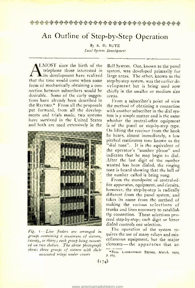
Fig. i -Line finders are arranged groups containing a maximum of sixteen, twenty, or thirty; each group being mount- ed on two shelves. The above photograph shows three groups of sixteen with their
associated relays under covers
in
Bell System. One, known as the panel system, was developed primarily for large areas. The other, known as the step -by -step system, was the earlier de- velopment but is being used now chiefly in the smaller or medium size areas.
From a subscriber's point of view the method of obtaining a connection with another subscriber in the dial sys- tem is a simple matter and is the same whether the central -office equipment is of the panel or step -by -step type. On lifting the receiver from the hook he hears, almost immediately, a low pitched continuous tone known as the "dial tone ". It is the equivalent of the operator's "number please" and indicates that he may begin to dial. After the last digit of the number wanted has been dialed, the ringing tone is heard showing that the bell of the number called is being rung.
From the standpoint of central -of- fice apparatus, equipment, and circuits, however, the step -by -step is radically different from the panel system, and takes its name from the method of making the various selections of trunks and lines necessary to establish the connection. These selections pro- ceed step -by -step; each digit or letter dialed controls one selection.
The operation of the system re- quires the use of many relays and mis- cellaneous equipment, but the major elements -the apparatus that ac-
tually makes the successive selections -are of three types : line finders, se- lectors, and connectors. In general appearance these are all very much alike- as may be seen from Figures I, 2 and 3 -but in details of con- struction, methods of mounting and operating, and in circuits, there are important differences between them.
Line finders - previously described at some length* - locate the line that is originating a call and connect it through to the first of a series of se- lectors. Selectors, varying in number depending on the size of the area, make the intermediate selections and after the second from the last digit is
dialed connect the calling line to one of a group of connectors. The con- nector makes the final connection to the line called and rings the bell if the line is not busy. Were the line already in use, a busy tone would be returned to the calling subscriber to apprise him of the fact.
Assume, for example, that a sub- scriber in an area in which there is only one central office, wishes to call number 8249. The act of lifting the receiver from the hook starts one of a group of line finders searching for the calling line. With each group of line finders, as many as Zoo lines may be associated, and the finder that starts to act is one of those that has the line of the calling subscriber asso- ciated with it. Controlled by associated relays, the line finder moves up rap- idly step -by -step till it reaches the level containing the calling line and then around to the particular line itself. The location of the calling line by the line finder causes a connection to be made to the first selector, and imme- diately "dial tone" is returned to the
* BELL LABORATORIES RECORD, February, i929, p. 236.
11751.
subscriber. The speed with which this connection is made may be judged by the fact that dial tone is usually heard by the time the receiver reaches the subscriber's ear.
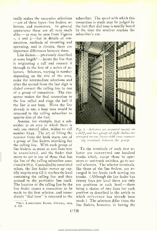
Fig. 2- Selectors are mounted twenty on a shelf, and two groups of eight shelves are arranged on one frame with cross connect-
ing terminals between the groups
To the terminals of each first se- lector are connected one hundred trunks which, except those to oper- ators or out -trunk switches, go to sec- ond selectors. The selector terminals, like those of the line finders, are ar- ranged in ten levels each serving ten trunks. (Although the line finder has twenty lines per level there are only ten positions in each level -there being a choice of two lines for each position as described in the article to which reference has already been made.) The selectors differ from the line finders, however, in having the
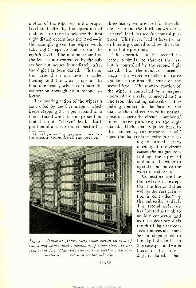
motion of the wiper up to the proper level controlled by the operation of dialing. For the first selector the first digit dialed determines the level -in the example given the wiper would take eight steps up and stop at the eighth level. The motion around on the level is not controlled by the sub- scriber but occurs immediately after the digit has been dialed. This mo- tion around on one level is called hunting and the wiper stops at the first idle trunk, which continues the connection through to a second se- lector.
The hunting action of the wipers is
controlled by another magnet which keeps stepping the wiper around till a line is found which has no ground po- tential on its "sleeve" lead. Each position of a selector or connector has
e Except for hunting connectors. See BELL LABORATORIES RECORD, March, 1929, page 291.
three leads; two are used for the talk- ing circuit and the third, known as the "sleeve" lead, is used for control pur- poses. This sleeve lead of busy trunks or lines is grounded to allow the selec- tion of idle positions.
The operation of the second se- lector is similar to that of the first but is controlled by the second digit dialed. For the number chosen - 8249 -the wiper will step up twice and select the first idle trunk on the second level. The upward motion of the wiper is controlled by a magnet operated by a relay connected to the line from the calling subscriber. The pulsing contacts in the base of the dial, as the dial returns to its normal position, opens the circuit a number of times corresponding to the digit dialed. If the dial is pulled back to the number 2, for instance, it will open the dial contacts twice in return-
ing to normal. Each opening of the circuit causes the magnet con- trolling the upward motion of the wiper to operate and move the wiper one step up.
Connectors are like the selectors except that the horizontal as well as the vertical mo- tion is controlled* by the subscriber's dial. The second selector has located a trunk to an idle connector and as the subscriber dials the third digit the con- nector moves up a num- ber of steps equal to
of the digit dialed -in this case 4 - and waits there till the fourth digit is dialed. Dial-
Fig. 3- Connector frames carry seven shelves on each which may be mounted a maximum of either eleven or six- teen connectors. One connector on each shelf is a test con-
ing of the last digit moves the wipers of the connector around on the fourth level to the ninth position. To the terminals of this position are con- nected the wires running to subscri-
used depends on the trunk chosen by the second selector. Similarly the banks of the selectors are arranged in groups and their "bank contacts" multipled together. The number of
TRUNKS TO LINES 8000T08099 LINES 8900T08999 L INES 8800T08899 o-e LINES 8700108799 LINES 8600T08699 LINES MOO T08599
z LINES 8400T08499 x LINES 8300708399
LINES 8200T08299 'x LINES 8100T08199
TERMINALS-TERMINALS 456
0 9% 8=
W7= w6= 2= xd% éL `°2= c-
1=
Toy OLIN ES
M8201T08200 m 8 2 9 1 7 0 8 2 9 0 m 8281 TO 8280 :82 71 10 8270
- A c 826170 8260 °x8251 10 8250
-_ CALLED
SUBSCRIBERS] SET 1
c - _ t x 8241 10 8240
CALLING SUBSCRIBERS
SET
= 823110 8230 eo 8221T08220
821170 8210
LINE FINDER FIRST SELECTOR SECOND SELECTOR CONNECTOR
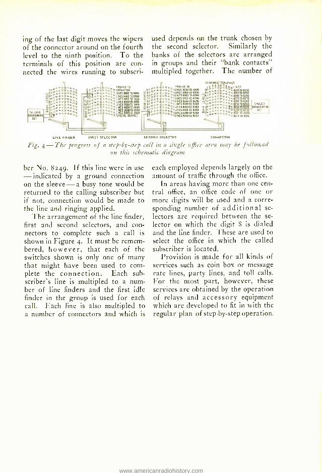
Fig. 4 -The progress of a step -by -step call in a single office area may be followed on this schematic diagram
ber No. 8249. If this line were in use - indicated by a ground connection on the sleeve -a busy tone would be returned to the calling subscriber but if not, connection would be made to the line and ringing applied.
The arrangement of the line finder, first and second selectors, and con- nectors to complete such a call is
shown in Figure 4. It must be remem- bered, however, that each of the switches shown is only one of many that might have been used to com- plete the connection. Each sub- scriber's line is multipled to a num- ber of line finders and the first idle finder in the group is used for each call. Each line is also multipled to a number of connectors and which is
each employed depends largely on the amount of traffic through the office.
In areas having more than one cen- tral office, an office code of one or more digits will be used and a corre- sponding number of additional se- lectors are required between the se- lector on which the digit 8 is dialed and the line finder. These are used to select the office in which the called subscriber is located.
Provision is made for all kinds of services such as coin box or message rate lines, party lines, and toll calls. For the most part, however, these services are obtained by the operation of relays and accessory equipment which are developed to fit in with the regular plan of step -by -step operation.
A Method for Estimating Audible Frequencies By W. A. MARRISON
Transmission Research
IT is often desirable when making calibrations and other frequency measurements to be able to es-
timate the frequency of a tone with- out the aid of elaborate standards or measuring apparatus. By a simple use of musical intervals which nearly everyone can learn easily to recog- nize, any frequency in the range from approximately 5o to 4000 cycles (roughly 7 octaves) can be estimated
by ear with considerable accuracy, given a single frequency in this range.
The single frequency may be ob- tained from a fork, reed, or pitch pipe, Some people with an "absolute ear" can recognize certain pitches without any auxiliary means; violin- ists frequently can tune their instru- ments to standard pitch without any outside aid. In the absence of any of these aids, however, one can have an approximate standard in his own voice or whistle. The lowest notes one can sing and whistle are quite defi- nite and can usually be relied upon to within to per cent. These lowest notes may conveniently be used as ref- erence standards in terms of which the frequency of any other musical tone may be estimated.
For men, the lowest singing tone will range with individuals from 6o to 120 cycles and the lowest whistle from 500 to boo cycles. For women the singing tone is approximately one octave higher. One may readily cali- brate his "standards" by means of a piano with the aid of the accompany-
ing chart in which the frequency of every note of the equally- tempered scale is given in a range of eight oc- taves. The note known as middle "C" has a frequency of 258 cycles. One must be sure, in making this test, that the sung tone is identified with the correct piano note, and not with one an octave higher or lower. Strange as it may seem, one who has had some experience with singing is likely to make this mistake since men are accustomed to sing an octave lower than the air is usually played.
A violin tuner, consisting of four small reeds tuned to G, D, A, E, is a convenient reference standard to use for estimating frequencies. The fre- quencies of the four tones are 194, 290, 435 and 652 respectively. With an error of only about three per cent these may be assumed to be 200, 300, 450 and 650, which are sufficiently good approximations for our purpose.
Having one's standard of fre- quency, all that remains is to learn to recognize musical intervals and to know the corresponding frequency ra- tios. This is easily done because the frequencies which, sounded together, are the most pleasing bear the sim- plest frequency ratios to each other. This is characteristic of pairs of tones in both the major and minor scales. These scales were developed because they were capable of pleasing musical combinations; the simple relation be- tween the frequencies was discovered long after the scales were invented.
Bach's invention of the equally tem- pered scale did not change this situa- tion. Although in the equally tem- pered scale the intervals correspond- ing to the simple frequency ratios are not perfect, they are sufficiently good approximations to satisfy most ears. In the equally tempered scale the maximum deviation from a perfect interval is less than one per cent or a fifth of a semi -tone.
In referring to intervals it is best to retain the usual musical notation. The notes, or degrees, of the scale are known as the `first', `second', etc., to the `eighth' in rising pitch. The mu- sical interval between the first degree of the scale and any other is called by the name of the higher degree. Thus
the interval between the first and fourth degree of the scale is known as
a `fourth'. The intervals thus defined which are the most easily recognized are listed in the following table with the corresponding frequency ratios:
Interval Frequency Ratio
Eighth (octave) 2'I Fifth . 3:2 Fourth 4:3 Third (major) 5:4 Third (minor) 6.5
Intervals a whole tone or a semi- tone apart may also be estimated quite accurately. The frequency ratios corresponding to these are as follows:
Frequency Ratio 9 :8
Io:9
Interval Whole tone (large)
" " (small) Semi -tone 16 :15
The frequency ratios between the
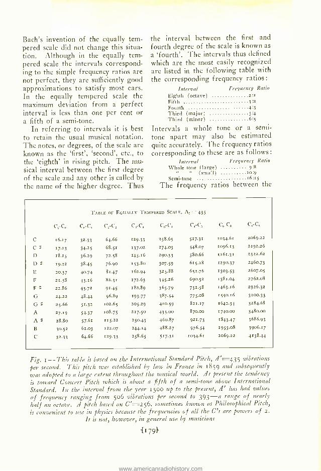
TABLE OF EQUALLY TEMPERED SCALE, A, =435
C1-C, c-c1 C1-C, C,-C, C,-C, C,-C, C,-C8 c- C,
C 16.17 32.33 64.66 129.33 258.65 517.31 1034.61 2069.22
D 18.r5 36.29 72.58 145.16 29033 580.66 1161.31 2322.62
D # 19.22 38.45 76.90 153.806 307.59 615.18 1230.37 2460.73
E 20.37 40.74 81.47 162.94 325.88 651.76 1303.53 2607.05
F 21.58 43.16 86.31 172.63 345.26 690.52 1381.04 2762.08
F f: 22.86 45.72 91.45 182.89 365.79 731.58 1463.16 2926.32
G 2¢.z2 48.4¢ 9689 193.77 38754 775.08 1550.16 3100.33
G g 25.66 51.32 102.65 205.29 410.59 821.17 1642.34 3284.68
A 27.19 54.37 108.75 217.50 435.00 870.00 17.}0.00 3480.00
A # 28.80 57.61 115.22 230.43 460.87 921.73 1843.47 3686.93
B 30.52 61.03 122.07 244.14 488.27 976.54 1953.08 3906.17
C 32.33 64.66 129.33 258.65 517.31 1034.61 2069.22 4138.44
Fig. i -This table is based on the International Standard Pitch, A' =435 vibrations per second. This pitch was established by law in France in 1859 and subsequently
was adopted to a large extent throughout the musical world. At present the tendency
is toward Concert Pitch which is about a fifth of a semi -tone above International Standard. In the interval from the year 1500 up to the present, if' has had values of frequency ranging from 5o6 vibrations per second to 393 -a range of nearly half an octave. if pitch based on C=256, sometimes known as Philosophical Pitch, is convenient to use in physics because the frequencies of all the C's are powers of 2.
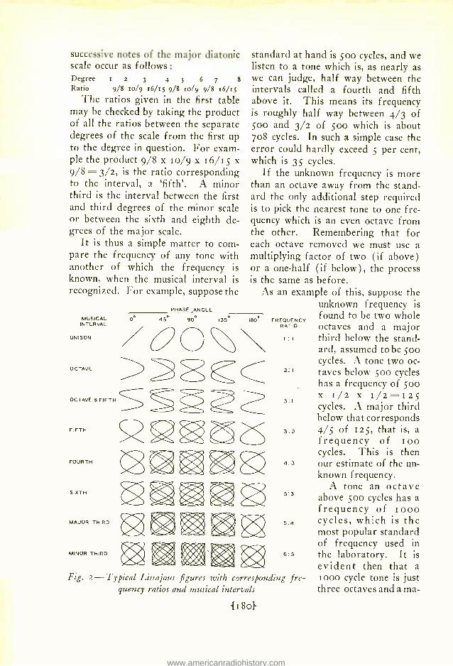
successive notes of the major diatonic scale occur as follows: Degree i z 3 4 5 6 7 8
Ratio 9/8 to/9 16 /15 9/8 to/9 9/8 z6 /z5
The ratios given in the first table may be checked by taking the product of all the ratios between the separate degrees of the scale from the first up to the degree in question. For exam- ple the product 9/8 x 10/9 x 16/15 x 9/8=3/2, is the ratio corresponding to the interval, a `fifth'. A minor third is the interval between the first and third degrees of the minor scale or between the sixth and eighth de- grees of the major scale.
It is thus a simple matter to com- pare the frequency of any tone with another of which the frequency is known, when the musical interval is recognized. For example, suppose the
MUSICAL INTERVAL
standard at hand is soo cycles, and we listen to a tone which is, as nearly as we can judge, half way between the intervals called a fourth and fifth above it. This means its frequency is roughly half way between 4/3 of 500 and 3/2 of 500 which is about 708 cycles. In such a simple case the error could hardly exceed 5 per cent, which is 35 cycles.
If the unknown frequency is more than an octave away from the stand- ard the only additional step required is to pick the nearest tone to one fre- quency which is an even octave from the other. Remembering that for each octave removed we must use a multiplying factor of two (if above) or a one -half (if below), the process is the same as before.
As an example of this, suppose the unknown frequency is found to be two whole octaves and a major third below the stand- ard, assumed to be 500 cycles. A tone two oc-
2 ' taves below 50o cycles has a frequency of 500 x I/2 x I/2 =1 25
3:1
cycles. A major third below that corresponds
3:2 4/5 of 125, that is, a frequency of ioo cycles. This is then
4:3 our estimate of the un- known frequency.
A tone an octave 5:3 above Soo cycles has a
frequency of loon 5:4 cycles, which is the
most popular standard of frequency used in
6:5 the laboratory. It is evident then that a t000 cycle tone is just three octaves and a ma-
PHASE ANGLE
0 45 900 135 I8Ó
O O
\ RATIO
UNISON / O 0 o
FREQUENCY
OCTAVE
OCTAV
FIFTH
FOURTH
SIXTH
MAJOR THIRD
MINOR THIRD
>>.0 Cc >
LAyC
I : I
Fig. 2- Typical Lissajous figures with corresponding fre- quency ratios and musical intervals
jor third above ioo cycles. This is true of any two tones having fre- quencies in the ratio of io to i.
A knowledge of the simple fre- quency relations corresponding to mu- sical intervals is of value when mak- ing frequency comparisons by means of the Braun tube. It is common knowledge that simple Lissajous fig- ures are produced when frequencies related by a simple fraction are com- pared on the Braun tube. The fact that the intervals between frequencies which form simple Braun tube figures can easily be recognized by ear is of considerable value in making such measurements. In Figure 2 the Lis - sajous figures are shown correspond- ing to the simpler frequency ratios for five different phase angles, referred to the higher frequency in each case. If the ratio of the frequencies is not ex- actly the value of the fraction indi- cated, the figure will change slowly through all of the configurations shown. Each of the figures shown corresponds to a definite and easily recognized musical interval. In Fig- ure 2 the musical intervals are indi- cated beside the corresponding Lissa - jous figures.
The relations just pointed out are of value both in estimating unknown frequencies and in making actual cali- brations. If for example a fairly open stationary figure is observed on the Braun tube, and the musical interval
is recognized as a major third, the exact ratio of the frequencies will be found to be 5 :4. It may in some cases be difficult to recognize the difference between 5 :4 and 6:5 Lissajous figure, but if the frequencies being compared are in the audible range they can be positively identified by ear. If it is desired to adjust a variable frequency to, say, 400 cycles in terms of a fixed frequency of 30o cycles, it will be found convenient first to adjust the variable frequency by ear to a `fourth' above the fixed frequency, after which only a very slight adjustment will be required. The adjustment made by ear should be so close that the desired Braun tube figure will be obtained, al- though it may be moving rapidly. The final adjustment is made by changing the variable frequency until the fig- ure remains stationary.
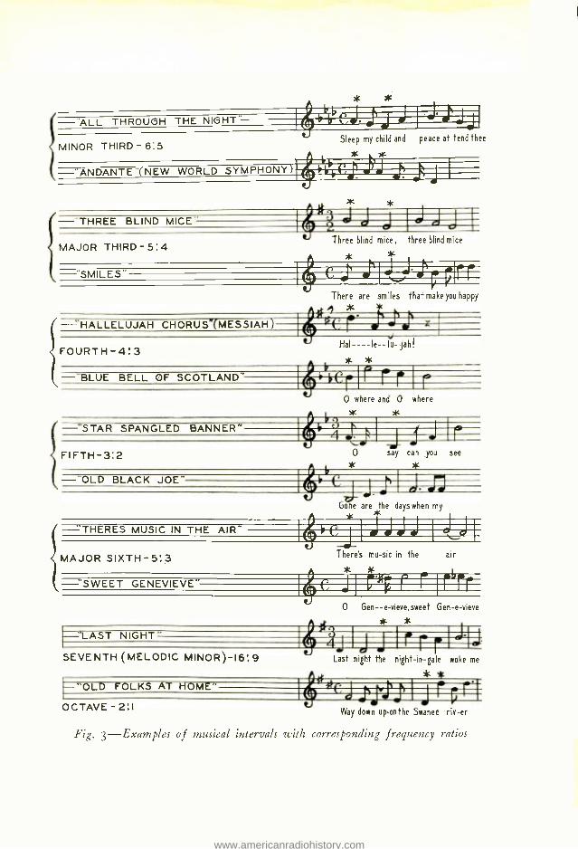
A convenient way to visualize mu- sical intervals in question is to note simple melodies in which they occur. In Figure 3, a number of familiar melodies are indicated which illus- trate the intervals mentioned above, giving the names of the intervals and the corresponding frequency ratios. Intervals of the sixth and seventh are also given. These are easily recog- nized although the frequency ratios are not so simple as the others. In- tervals visualized in this way are in- stantly available for comparing by ear any two tones in the audible range.
Vice -President Charlesworth Addresses the Telephone Pioneers in Minneapolis
F. MPHASIZING the indispen- sability of research to the at-
J tainment of the Bell System's announced purpose of giving the best and most comprehensive service at the least possible cost, H. P. Charles - worth outlined to the Convention of Telephone Pioneers some of the more recent achievements of tele- phone development. He contrasted the cramped space and meager equipment available to Dr. Bell in the small room in Boston, where the telephone was born, to the present Laboratories with their personnel of nearly 5,000 people and budget of over fifteen mil- lion dollars a year. The same spirit of research that enabled Bell to over- ride all obstacles still vitalizes the ac- tivities now being carried on with the enormously greater facilities.
Among the many developments touched upon, Mr. Charlesworth re- ferred briefly to the improvements in loading coils, condensers, relays, vacuum tubes, carrier, cables, and other forms of apparatus and ma- terials which have made possible the great strides in local and long distance as well as the transatlantic tele- phone service.
Recent progress in television and developments leading to talking mo- tion pictures, aids to hearing, the arti- ficial larynx, and other by- products of telephone research were also men- tioned.
The rapid extension of the dial system was discussed, and it was
pointed out that according to esti- mates about one -half of the stations in the Bell System would be operated on a dial basis by 1934. Connected with this growth of dial telephony is the interesting extension of automatic testing methods. As an example of this, mention was made of a part of the panel system which tests its own circuits before the call is advanced to other apparatus. If trouble exists, other equipment is automatically sub- stituted, and the subscriber, knowing nothing of this rapid testing and sub- stitution of apparatus, gets his num- ber with no apparent delay. In cases of persistent trouble, an alarm is
sounded and lamps lighted to indi- cate its location.
Among the many developments connected with the dial system, ref- erence was also made to the "call in- dicator" -used to indicate to a man- ual operator a number called from a
dial office. As the latest apparatus for performing this function under certain conditions, he demonstrated the new "call announcer ". A number dialed, instead of being flashed to the operator by illuminated numbers as with the call indicator, is spoken to her by mechanical methods. In demonstrating this equipment, Mr. Charlesworth called the Laboratories in New York and requested that some- one dial a telephone number. When the number was dialed, equipment translated the number into words, and the Pioneers in the Auditorium
heard a mechanical voice clearly call- ing out the number dialed.
Among the other developments de- scribed was the transatlantic radio, and Mr. Charlesworth told of a re- cent test in which he had taken part, involving a combined radio and land line connection of t S,000 miles be- tween New York and Australia by way of London. "How truly this in- dicates that we are becoming a world of neighbors," said Mr. Charles - worth, "It recalls to my mind a state- ment made by General J. J. Carty. These were his words:
"It is the mission of the Pioneers, their successors, and their associates among all nations, to build up a tele- phone system extending to every part of the world, and connecting together all the people of the earth.
"I believe that the art which was founded by Alexander Graham Bell, our first Pioneer, will provide the means for transmitting throughout the earth a great voice proclaiming the dawn of a new era in which will be realized that grandest of all our earthly aspirations -the brother- hood of man."
While discussing radio develop- ments, an interesting demonstration of an airplane radio telephone was staged for the benefit of the audience. Captain Brooks, flying over New Jer- sey, placed a call for Mr. Charles - worth in Minneapolis, and the ensu- ing conversation was heard by the en- tire audience through the use of loud
speakers. Captain Brooks was asked to have Mr. McCulloh, President of the New York Telephone Company, brought in on the connection, and the Pioneers had the interesting experi- ence of hearing from their incoming President in this very unusual manner.
The talk throughout was illustrated by slides, and in many cases improve- ments that have resulted from devel- opment and research were shown by the presence of the actual equipment and apparatus on the platform. In concluding his talk, Mr. Charles - worth quoted:
"There is a great thought under- lying the wonderful developments of the world's greatest telephone system. Since Dr. Bell's discovery and inven- tion opened the way, the progress of the electrical transmission of speech and the expansion of the system have been something more than a great commercial enterprise. It has been tinged throughout with idealism, and its history is replete with the roman- ticism of the knight- errant and the pa- tient zeal of the ancient alchemist.
"It has been developed out of noth- ing by wresting from Nature's bound- less store her hidden secrets and ap- plying them to the problems of speech transmission. The future is assured, for lying outside the boundaries of our present knowledge, away off in
the infinite, is a store of resources which will be moulded to the use of mankind by the men and women of the Bell System."
H. P. CHARLESwoRTII has been ap- pointed a member of the Edison Medal Committee of the American Institute of Electrical Engineers to fill out the unexpired part of Mr. Craft's term. The Edison Medal is awarded annually for meritorious achievement in electrical science, en- gineering or the arts to a resident of either the United States or Canada.
1\Ir. Charlesworth has also been notified of his reappointment for a three -year term to the Board of Trustees of the United Engineering Society. In addition he has been ap- pointed a member of the group of Directors of Industrial Research.
On October 15, the members of lIr. Charlesworth's former staff in the Operation and Engineering De- partment of the American Telephone and Telegraph Company presented him with a gold watch and pencil.
* * * *
WHAT IS BELIEVED to be the long- est telephone conversation carried on with artificial voices occurred on Oc- tober 13. Using the artificial larynx and bellows, S. P. Grace talked from his office in the Laboratories to Col- onel Robert Bradford Marshall, who was using similar apparatus at the office of F. L. McNally of the Pacific Telephone and Telegraph Company at Sacramento. Colonel Marshall, who is State Landscape Architect and Engineer of the Department of Pub- lic works at Sacramento, was ren- dered mute through an operation in which his larynx was removed.
Colonel Marshall called on Mr. Grace in San Francisco last spring and
asked for a demonstration of the new experimental type of artificial larynx. Since his operation he was accom- panied on his travels by his wife who had learned to read his lips and thus conveyed his ideas to others. He had attempted to use the commercial type of larynx which he found unsatisfac- tory owing to the peculiar configura- tion at the opening of his throat. Within a few minutes he was able to talk well with the new type instru- ment and Mr. Grace arranged to have one sent to him from the Labo- ratories.
Colonel Marshall was formerly Chief of the United States Geograph- ical Survey, and had to give up his position because of loss of his voice. He is the author of the Marshall Ir- rigation Act and is considered an au- thority on irrigation matters.
* * * *
THE BOEING AIR LINES have an- nounced that they are about to install Western Electric radio telephone equipment on their transcontinental mail and passenger transport air- planes. Twenty -two ground stations will serve the Chicago -San Francisco and the Los Angeles -Seattle routes. Apparatus will he that developed by these Laboratories and will include, for the planes, a long -wave receiver for weather and beacon signals, a short -wave receiver, and a fifty -watt transmitter for communication with the ground station.
* * * *
THE REGULAR meeting of the Col- loquium was held on October 28. A. R. Olpin spoke on Use of Dielectrics
to Sensitize Photoelectric Cells to Red and Infra -red Light.
* * * *
AT THE instance of P. L. Schauble, General Information Manager of the Bell Telephone Company of Pennsyl- vania, members of Mr. Schauble's de- partment engaged in publicity work made an inspection tour of the Labo- ratories under the guidance of G. F. Fowler during the latter part of Oc- tober. Mr. Schauble accompanied the second of the two groups of his men that visited the Laboratories.
* * * *
ON NOVEMBER 12, President -elect Robert Gordon Sproul of the Univer- sity of California made an inspection tour of the Laboratories and was en- tertained at luncheon by Mr. Charles - worth and his staff and members of the Educational Department. Dr. Sproul was later a guest at a dinner given at the Western Universities Club by California alumni employed in the Laboratories. Those present included P. J. Brownscombe, C. J. Christensen, S. A. Clark, F. A. Coles, R. C. Dehmel, R. J. Heffner, W. A. Munson, F. A. Polkinghorn, W. J. Thompson, C. S. Yeutter, N. C. Youngstrom and Edgar Tourraine of Western Electric at Kearny.
* * * *
GROUP HEADS of the Department of Development and Research were guests at two of the recent Executive Conference luncheons. Introduced by Mr. Charlesworth, L. F. Morehouse spoke October 24 on equipment de- velopment, and O. B. BLACKWELL November 7 on transmission develop- ment. Mr. Morehouse was accom- panied by H. M. Bascom, B. C. Bel- lows, I. W. Green, R. W. Morris, and R. D. Parker of his staff, and
Mr. Blackwell by J. R. Carson, A. B.
Clark, Lloyd Espenschied and W. H. Martin.
ACCOMPANIED by G. H. Downes of the American Telephone and Tele- graph Company, O. C. Eliason visit- ed Washington to inspect the trial installation of a new type of distri- buting frame wire.
H. H. GLENN inspected switch- board cable being installed in the new telephone exchange in Roselle, New Jersey.
C. A. WEBBER visited Baltimore in
connection with the splicing of dis- tributing frame wire at the Point Breeze plant of Western Electric.
H. S. SMITH made a trip to the General Electric plant at Schenectady regarding the development of special cable for use in high frequency tele- phone circuits.
DURING the early part of the month E. B. Wheeler visited Hawthorne to discuss enameled wire and textile de- velopment, and the National Carbon Company at Cleveland to discuss sev- eral matters pertaining to dry bat- teries.
While on this trip Mr. Wheeler at- tended the twenty -fifth anniversary of the honorary electrical engineering fraternity, Eta Kappa Nu, of which he was one of the founders at the University of Illinois in 1904.
L. A. ELMER was at Hawthorne conducting experiments and tests in connection with the 7o7 -A Drive.
nual meeting of the Telephone Pio- neers at Minneapolis, as a delegate of the Edward J. Hall chapter.
L. N. HAMPTON and C. G. Mc- CORMICK visited Hawthorne and Kearny to study recent manufacturing developments in connection with the presentation of an out -of -hour course on Manufacturing Methods.
B. FREILE visited the Automatic Electric Company and the Hawthorne plant for discussions of step -by -step apparatus problems.
H. BROADWELL visited the step -by- step office at Stamford, Connecticut, to obtain data in regard to the rede- sign of the Automatic Electric testing interrupter.
F. S. KAMMERER visited the North exchange of the Chesapeake and Po- tomac Telephone Company at Wash- ington in connection with the installa- tion of new type detachable feeder brushes on No. 266 type selectors.
J. R. IRWIN visited the Illinois Bell Telephone Company toll office in Chi- cago in connection with relay contact investigations. He also discussed re- cent contact developments with the Manufacturing Department at Haw- thorne.
F. C. Kum spent a week at Haw- thorne for engineering training.
R. BURNS was at Hawthorne to discuss problems on finishes and com- pounds. He also visited the experi- mental station of the Dupont Com- pany on similar investigations.
W. W. WERRING attended a meet- ing of the American Society of Me- chanical Engineers at Akron in con- nection with the formation of a joint A.S.M.E- A.S.T.M. committee for the study of impact. While on this trip he visited Hawthorne to confer on problems of molded insulation and on his return attended the meeting of
the A.S.T.M. committee on insulating materials at Pittsburgh.
F. W. CUNNINGHAM made a trip to the Pacific Coast with A. J. Eaves of the Graybar Electric Company and H. E. Young of the Western Electric Company visiting western broadcast- ing stations.
A. B. BAILEY supervised the instal- lation of speech input equipment in the Boston studio of the Matheson Radio Company of Gloucester. He also made a field strength survey of Station WEEI of the Edison Electric Illuminating Company of Boston.
W. L. BLACK recently visited Sta- tion WHAM operated by the Strom - berg- Carlson Telephone Manufactur- ing Company in Rochester. He later directed the installation of speech in- put equipment for the Chicago Daily News at Chicago.
J. C. HERBER recently supervised the conversions to crystal control and high percentage modulation of the i kw. transmitter of the city of Jack- sonville, Florida, and the 5 kw. trans- mitter of WJR, Inc. of Pontiac, Michigan. He also supervised the in- stallation of a 5 kw. broadcasting equipment for the Milwaukee Journal.
F. A. HINNERS made surveys for t kw. broadcasting equipments for the American Broadcasters, Inc., of De- troit, Gimbel Brothers, Pittsburg, and the Monumental Radio Company of Baltimore. He inspected the t kw. station of the Woodmen of the World, Omaha, Nebraska, and super- vised the installation of I kw. broad- casting equipment for the Commer- cial Radio Service Company of Co- lumbus, Ohio.
W. L. TIERNEY has returned to the Laboratories after a stay of fif- teen months on the Pacific Coast. He concluded his visit with a survey for
a i kw. radio broadcasting equipment for the Pickwick Broadcasting Com- pany of Los Angeles, California, and an inspection of the I kw. broadcast- ing equipment operated by the Tenth Avenue Baptist Church of Oakland, California. He has begun a survey for the location of a 5o kw. radio telephone broadcasting equipment purchased by the Columbia Broad- casting System for their station WABC.
O. W. TOWNER supervised the in- stallation of i kw. broadcasting equip- ments for the Mona Motor Oil Com- pany of Council Bluffs, Iowa; the Texas Air Transport Broadcasting Company of Fort Worth, Texas; and the Pickwick Broadcasting Company of Los Angeles. He converted to crystal control and high percentage modulation the I kw. broadcasting equipment of the Pickwick Broadcast- ing Company at Oakland, California.
T Li
.agir
V. T. CALLAHAN and F. F. SIE- BERT visited the Buffalo Gasoline Mo- tor Company at Buffalo to discuss several new design elements for gas- oline engines.
R. P. JUTSON inspected trial instal- lations of new power plant features at Greensboro and Durham, North Carolina.
H. T. LANGABEER went to Syra- cuse to inspect the installation of a
large automatic power plant at of- fice 8 there.
D. R. FENLON was at the Hart- ford step -by -step central office in con- nection with a trial being made on line
switches to reduce double connections. J. R. LAFFERANDRE visited the
short wave radio receiving station at Forked River, New Jersey, now an ex- perimental service for ship -to -shore radio telephone communication with the steamship Leviathan.
F. R. JEFFREYS has been at Net - cong supervising the installation of voice frequency terminal equipment used in connection with the short -wave transoceanic radio telephone channels to England and South America.
H. D. KELSO went to Philadelphia in regard to test splicing of quadded cable in toll offices.
R. PETERSEN and H. E. MARTING visited Worcester, Massachusetts, in connection with the first installation of a new type of mezzanine platform which has recently been standardized.
E. J. KANE and J. E. GREENE were at Stamford, Connecticut, in company with American Telephone and Telegraph and Western Electric engineers to observe results on sev- eral recent changes made in the step - by -step equipment to facilitate instal- lation and maintenance.
D. S. MYERS and R. PETERSEN visited Wilmington on matters con- cerned with a new design of super- structure which was installed at Wil- mington main office.
W. J. LACERTE made several trips to Stamford, Connecticut, in connec- tion with the initial installation of message rate trunks with delayed in- terval. He also spent some time at Syracuse in connection with a pre - selector trial, and visited Hartford on a trial of modifications to reduce double connections.
F. A. KORN visited Pittsburgh to study circuit conditions at the Her - minie step -by -step central office.
H. M. PRUDEN has sailed for Buenos Aires where it is expected he
will stay for six months in connection with the installation of the Buenos Aires to New York radio channel.
J. G. WALSH was in Hartford and Springfield, making field studies on pulse correctors.
E. L. BAULCH made a trip to Chi- cago where he observed the opera- tion of terminal repeaters with pad control apparatus.
W. F. KANNENBERG visited Darl- ington, South Carolina, in connection with the installation of the new auto- matic pilot channel equipment for new repeaters here. He later spent sev- eral days checking adjustments of the automatic pilot channel equipment in- stalled at Denmark, South Carolina, and Savannah, Georgia.
C. M. HEMMER was also out on the automatic pilot channel job at West Palm Beach and Jacksonville.
H. R. CLARKE, L. W. GILES and W. C. JONES were in Hawthorne in connection with the high quality re- ceiver for the deskstand. Mr. Jones also attended the convention of the United States Independent Telephone Association at Chicago.
H. A. FREDERICK left on October 3o for Hollywood to visit sound pic- ture studios in regard to work on re- cording and reproducing instruments.
H. A. LARLEE attended the con- vention of the United States Inde- pendent Telephone Association at Chi- cago. While on this trip he went to Hawthorne to review the handset job in company with engineers of the Northern Electric Company.
G. M. BOUTON visited New Castle, Pennsylvania, during the latter part of October to observe the installation of a new type of cable.
R. M. BURNS has been at New Or- leans studying the corrosion of cable sheath.
R. M. BURNS, C. C. HOPKINS and A. E. SCHUH made an inspection tour of the General Research Laboratories of the Du Pont Company at Wilming- ton.
J. M. FINCH and A. C. WALKER attended the meeting of the American Society for Testing Materials at Pitts- burgh.
A. N. GRAY visited the H. L. Scott Company at Providence to confer on new uses of the rubber compression machine.
H. E. HARING and C. L. HIPPEN- STEEL were at New Orleans during the month of September and part of October studying the corrosion of cable sheath.
C. C. HIPKINS attended a meeting of the American Society for Testing Materials sub -committee on raw ma- terial testing for lacquers at Wash- ington.
A PAPER on short -wave telephone conversation with England was read by J. C. Schelleng before the meet- ing of the Institute of Radio Engi- neers on November 6.
HERBERT E. IVES gave a talk be- fore the Optical Society meeting at Ithaca. He spoke on Television in Color by the Beam Scanning Method. The meeting was also attended by Messrs. Olpin, Kingsbury, Johnsrud, Darrow and Germer.
J. A. BECKER presented before the National Academy of Arts and Sciences, meeting at Princeton, No- vember 18, a theory of the increase in electron emission due to adsorbed ions. This theory explains a number
of experimental facts and has been used to predict a number of later -veri- fied phenomena.
E. PETERSON has returned from California where with A. G. Landeen he has been making studies on the Catalina cable for future use on the transatlantic telephone cable. Mr. Landeen is still in California engaged in further tests.
DURING THE PERIOD from October 6, to November 6, 1929, members of the Patent Department visited the fol- lowing cities in connection with the prosecution of patents: Washington: H. A. Burgess, H. A. Flammer, E. V. Griggs, J. F. McEneany, P. C. Smith; Toronto, E. W. Adams; Chi- cago, G. M. Campbell; Philadelphia, J. G. Roberts.
E. J. BONNESEN has been ap- pointed field engineer in the St. Louis area replacing H. W. Nylund who is now in New York on special assign- ment work.
R. J. NOSSAMAN visited New Ha- ven in connection with routine super- visory work, where he attended the current field review conference.
G. GARBACZ and I. W. WHITE - SIDE, field engineers in the Cleveland and Philadelphia areas, visited New
t .19I
York to confer with members of the department on field engineering ac- tivities.
DURING October and the latter part of September, the members of the Field Engineering force made a number of trips on routine and special investigation work.
D. S. BENDER and A. M. ELLIOTT visited New Haven and Albany, re- spectively, where they attended field review conferences.
G. GARBACZ made a trip to Ashta- bula, Canton, Columbus and Youngs- town, Ohio.
C. A. JOHNSON, JR., visited Mil- waukee and Kenosha, Wisconsin; and Champaign, Decatur, Peoria and Zion City, Illinois.
R. C. KAMPHAUSEN was in Cen- ter Line, Flint, Grand Rapids, Ho- well, Kalamazoo, Plymouth, Pontiac, Trenton and Wyandotte, Michigan; Bloomington, Illinois ; and Indian- apolis, Indiana.
I. W. WHITESIDE visited Wilming- ton, Delaware and Washington, D. C.
W. E. WHITWORTH made trips to Des Moines and Sioux City, Iowa; Duluth and Minneapolis, Minnesota; Fargo, North Dakota; and Denver.
T. L. OLIVER visited Birmingham, Alabama; New Orleans, Louisiana; and Memphis, Chattanooga and Nashville, Tennessee.
J. A. ST. CLAIR was in Portland, Oregon; Seattle, Washington; and Los Angeles, California.
E. J. BONNESEN visited Cisco, Dennison and Wichita, Kansas; Okla- homa City, Oklahoma; Little Rock, Arkansas; Abilene, Dallas, Houston and Fort Worth, Texas; and Green- ville, Maud, and Kansas City, Mis- souri.
18 -23, John Mills delivered a series of talks on the organization of re- search and development activities be- fore a special class of electrical seniors at Pennsylvania State College.
P. C. JONES delivered an address Recording and Reproducing of Sound Pictures before the Technology Club at Syracuse.
OUTSIDE PLANT DEVELOPMENT
C. D. HOCKER and F. F. FARNS- WORTH went to Washington during the early part of October to attend the Fall meeting of a sub -committee of the A. S. T. M. on ferrous metals. During the latter part of the month Mr. Hocker attended a committee meeting of the A. S. T. M. held at Pittsburgh and Altoona in connection with inspection of zinc- coated samples exposed outdoors.
J. M. HARDESTY was in Montreal, Canada, investigating the feasibility of the manufacture of vitrified clay conduit in Canada for use by the Ca- nadian Bell Telephone Company.
J. G. BREARLEY, G. M. BOUTON,
W. J. FARMER, in company with Western Electric and American Tele- phone and Telegraph engineers, made a trip to New Castle, Pennsylvania, on October 23 and 24 to observe a trial installation of some experimental cables. Mr. Brearley continued to Chicago on October 25 for a discus- sion of experimental handling tests on some new types of cables.
STAFF
ANDREW A. SCHWINN, H. H. HALL, and O. LINGEL have been elected to membership in the Edward J. Hall chapter of the Telephone Pioneers of America. ALBERT KRONENFELD, an Instru-
ment Maker in the General Shop, died October 26, 1929, at the age of 61 years. Mr. Kronenfeld's service with the Western Electric Company and the Laboratories dated from Sep- tember 26, 1905. For a number of years he was engaged in the manu- facture of telephones when our pres- ent building was one of the manufac- turing units of Western Electric.
Contributors to this Issue H. F. DODGE, S.B., Massachusetts
Institute of Technology, 1916; In- structor, Electrical Engineering, 1916- 17; A.M., Columbia University, 1922 ; Engineering Department, West- ern Electric Company, 1917-25; Bell Telephone Laboratories, 1925 -. Mr. Dodge was earlier associated with the development of telephone instruments and allied devices, and is now engaged in development work relating to the application of statistical methods to inspection engineering.
W. G. KNOX received the B.S. de- gree from the State College of North Carolina in 1906 and a special degree from Lafayette College in 1907.
After a year as Assistant Chief Chem- ist for the Northampton Portland Cement Company, he joined the Shop Chemical Laboratory of the Western Electric Company. Transferred to the Chemical Laboratories of the Re- search Department in 1912, he took charge of the investigation of finishes. Among his contributions to the field
are the metal plating tables now pub- lished by Lefax, and the method of depositing a gold spot on thin alumi- num and duralumin diaphragms, used first in the war for submarine- detect- ing microphones and now in condenser transmitters for a variety of purposes. He assisted in the development of the baked aluminum finishes now used on control office equipment, and of the specially finished colored handsets. Last fall Mr. Knox transferred to the Plant Department as Assistant Superintendent in charge of metal, japan, and lacquer finishing.
Two years in the Royal Air Force interrupted W. A. Marrison's at- tendance at Queens University, but eventually he received the B.Sc. de- gree from his alma mater as of the Class of 1918, and a master's degree from Harvard in 1921. Then enter- ing the Laboratories, his early work was on frequency -analysis. This led into studies of methods and apparatus for production of constant -frequency current, and in particular to the study of piezo -electric crystals. An out- growth of this was methods of syn- chronizing distant devices by accu- rate speed control ; these methods were
of great value in picture- transmission and television.
AFTER graduating from Pratt In- stitute in 1916, V. T. Callahan took the Student Course with the Diehl Manufacturing Co. and later similar work with the Public Service Electric Corp. In 1917 he went with the Lake Torpedo Boat Co., where he was engaged in the design, construc- tion, and testing of both electrical and mechanical equipment. Follow- ing five years service in this field he joined the Laboratories where he has been engaged in the design of reserve power plants for Central Offices.
BEFORE graduating from Cornell, S. J. Zammataro spent three summers on coil design with the Engineering Department of the Western Electric Company. After getting his E.E. de- gree in 1921, he joined the Technical Staff of what has since become Bell Telephone Laboratories and for four years was engaged in testing work and in the Special Products Laboratory. He later became interested in alter- nating current bridge measurements and now is supervisor in charge of this field.
E. D. BUTZ entered the employ of the Western Electric Company a few months after graduating from the Pennsylvania State College with the degree of B.S. in 1911. A year was spent in edu- cational work with the Installation Department in Chicago, and in 1912 he was transferred to the Transmission Laboratory at 463 West Street where he engaged in transmitter and loud- speaking re- ceiver development for seven years. After the war he was transferred to the Systems Development Depart- ment where he has been interested in the design and testing of step -by -step systems. For five years he has taught the step -by -step system in the out -of- hour classes and is at the present time
E. H. Clark
engaged in designing circuits for use in dial system "A" switchboards.
V. T. Callahan
the
AFTER some experi- ence in the independent field, E. H. Clark en- tered the Engineering Department of the Western Electric Com- pany in Chicago in 1905. In 1913 he was trans- ferred to the Systems Development Depart- ment in New York and shortly after took part in tests of the first semi -me- chanical office in Newark. Later he was assigned to
Circuit Development group and during the war he spent much time in Pittsburg expediting completion of much needed equipment. At present he is associated with the Fundamental Circuit Development group.
THE score of 187 made by Leona Feil still occupies first place in the women's bowling.
Its position is somewhat precarious, however, judging from the rate our bowlerettes are improving, and it soon may be known as just another high score. Such is the March of Progress! The bowlerettes have reached hitherto unsuspected heights and are constantly improving.
The substitutes, bowling at the Shelton, are coming along nicely. One finds quite a few Hudson Street girls at the Shelton mastering the fine art of bowling. After a few hours of
strenuous exercise the swimming pool is also an attractive feature. Occasion- ally we meet Alma Wyckoff there. Miss Wyckoff is one of our swimming in-
structors at the Carroll Club and she is always ready to give expert advice. All in all, the Shelton is the place to go on Friday nights.
Marion Kane, extension 774, has charge of the Substitute Committee.
RHYTHMIC DANCING
Starting November I I and continu- ing through January, the course of ten lessons offered to the women of the Bell Laboratories Club at the Noyes School of Rhythm is now in full swing.
Rhythm brings a lack of effort - rest-in all activities. The principles on which true dancing are based also
underlie every other activity which has to do with movement. This is
especially applicable in our everyday work where relaxa- tion is so important to our well- being. The tensed feeling that comes from sit- ting hunched over a typewriter for a few hours would soon disappear if we knew how to relax our muscles. This is what the Noyes School endeavors to teach us.
Through the Club we are given the course of ten lessons for $3.50. Miss Neill Clare on extension 1382 will be glad to give further information.
INDOOR GOLF
ARE You a good putter? If you are you should enter the two indoor golf tournaments arranged by the club for the season 1929-1930. The first will be held on the evening of December 5, the second on the eve- ning of January 3o, at the Miniature Golf Course of America, 41 East Forty- Second Street, New York City.
The same rules as in previous suc- cessful tournaments will prevail: thirty -six hole medal play qualifying round and eight flights of match play for those who qualify. One prize for low medal score in qualifying round and one prize for the winner of each flight, or nine prizes in all, will be awarded.
The entire course will be reserved for the club from 5 o'clock until the tournament is ended. Previous tour-
naments have ended around 9:30 o'clock which allows commuters to catch a fairly early train.
The same entry fee will prevail - $1.50 payable upon entry to D. D. Haggerty, Room 164.
GLEE CLUB
From the beautiful harmonies which come floating down from the eleventh floor Rest Room on Wed- nesday evenings, we know that the Glee Club members are busy practic-
ing new songs and perfecting old ones. Quite a few new tunes have been added to their rep- ertoire and by all in- dications a bigger and better Glee
Club is in the making. An added fea- ture this season is a five minute recess during which time one of the more gifted members of the Club entertains with vocal or instrumental selections. This is purely voluntary on the part of the members and quite a lot of talent has been unearthed in this way.
One of the parties for which the Glee Club is famous will be held the first part of December. Our genial director, Mr. Richards, will be mas- ter of ceremonies and a good time is expected. If you are interested in singing, it is not too late to join the Glee Club. Phone Miss Van Riper on extension 775 and she will give you full particulars.
SWIMMING
The month of December ushers in last of the women's swimming classes
held on Monday, Wednesday and Thursdays for the autumn season. All of the girls who attended these classes have felt that it has been beneficial to them.
Because of the Holidays, the win- ter classes will not start until January when a fourth class will be added to take care of the large attendance. The interest which has been shown in these classes has been very gratifying and we hope that such interest will continue.
BASKETBALL
To all girls who have played bas- ketball -this is a call to arms. The Bell Laboratories team has an en- viable reputation to uphold and this can only be done by cooperation and faithful attendance on practice nights. A team will be chosen to represent the Laboratories and, as was the custom last year, this team will meet teams from other commercial houses. Mr. Gittenberg will be our coach this sea- son and if we were as sure of the cali- bre of this year's team as we are of "Charley's" coach- ing, we could start singing our Victory Song. However, a lot of hard work has to be done be- fore we can hope to hold our own in open competition.
All positions on the team are open and it's a case of "the best woman wins ".
Call Marianne Grimm on extension 1153 for further particulars concern- ing women's basketball.
THE candidates for Bell Laboratories Club officers for the year 1930 have been selected by the nominating committee. Ballots will be mailed to all club members on Friday, Decem-
ber 13, and must be placed in the ballot boxes Monday, December 16,
between the hours of 8:3o A.M. and 6 :oo P.M. Ballot boxes will be
located in prominent places in each section on all floors of the build- ing. No employee who is not a member of the club will receive a
ballot. Club membership application forms may be obtained from department representatives or from the club secretary. Applications received after December 12 will not entitle the members to vote in
the current elections. The nominating committee which selected the candidates con-
sists of O. M. Glunt, D. D. Haggerty, H. F. Dodge, Miss M. F.
Kane, S. J. Stranahan, G. Rupp, T. C. Rice, P. B. Fairlamb, J. C.
Kennelty, F. W. Hultqvist and W. D. Stratton. The candidates are
Mi ERVIN J. Kelly and Daniel R. McCormack, candidates for the
office of president, are members of the Research and Staff De- partments respectively. Mr. Kelly received the B.S. degree from
the University of Missouri in 1914 and pursued post graduate studies in the University of Kentucky and the University of Chicago where he re- ceived the Ph.D. degree in 1918. Soon after completing his work at the University of Chicago he entered the research branch of the Western Electric Engineering Department. He is now Vacuum Tube Develop- ment Engineer and Vacuum Tube Shop Manager. Mr. McCormack came into the Engineering Department of the Western Electric Company as a clerk in 1919 after studying at Drakes' Business School and Cooper Union. He is now Office Manager of the Laboratories.
The candidates for first vice -president of the club are Leslie P. Bartheld and Thomas C. Rice. Mr. Bartheld's first work in the Western Electric Company was in the Systems Development Department as an engineering assistant. He came to the Western Electric Company directly after his graduation from Iowa State in 1921. Mr. Rice has had con- siderable experience in telephone work before he entered the inspection
branch of the Western Electric Company in 1916. With the exception of four months which he spent in the Systems Development Department, he has since then been a member of the Inspection Engineering Department.
Miss May Murtagh and Miss Mary Reddington are the candidates for second vice president of the club. Miss Murtagh is a member of the Apparatus Development Department and Miss Reddington of the Bureau of Publication. Both the candidates have been active workers in the club.