June 11, 2014; 1 PM (U.S. Central Time) DIAL IN NOW FOR AUDIO 1-877-406-7969 or 1-347-532-1806 PIN# 2603587# http://www.meetingzone.com/presenter/default.aspx Access Code2603587# Best Practice, Direct Evaporative Cooling Technology for Combustion Turbine By Pat Zeller, Munters Corporation Sponsored by: Turbine Inlet Cooling Association (TICA)
Please submit questions during the presentations by typing them into the “chat” window area of the screen
After the featured presentation is complete, we will answer your submitted questions
You may receive a online survey immediately following the webinar . We would appreciate your participation to:• Provide feedback on webinar series• Suggest other topics and speakers
Presentation Agenda
• Why turbine inlet cooling• Direct Evaporative Cooling for Combustion Turbines• How Direct Evaporative Cooling Works• Where Direct Evaporative Cooling Works • Examples• Design Considerations• Water Management• Technology Comparison
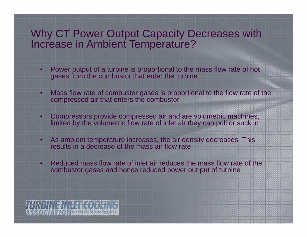
Why CT Power Output Capacity Decreases with Increase in Ambient Temperature?
• Power output of a turbine is proportional to the mass flow rate of hot gases from the combustor that enter the turbine
• Mass flow rate of combustor gases is proportional to the flow rate of the compressed air that enters the combustor
• Compressors provide compressed air and are volumetric machines, limited by the volumetric flow rate of inlet air they can pull or suck in
• As ambient temperature increases, the air density decreases. This results in a decrease of the mass air flow rate
• Reduced mass flow rate of inlet air reduces the mass flow rate of the combustor gases and hence reduced power out put of turbine
Smaller Capacity Systems More Sensitive to Ambient Temperature
Source: Solar Turbines
Capacity Loss of over 21% from ~10,750 kW to ~8,500 kW
Efficiency loss of over 8 % from HR of ~ 11,100 to ~12,000 Btu/kWh
Turbine Inlet Cooling Overcomes the Effects of the CT Flaws During Hot Weather
7 5
8 0
8 5
9 0
9 5
1 0 0
6 0 7 0 8 0 9 0 1 0 0
A m b ie n t D ry -B u lb T e m p e ra tu re , F
Net
CT
Pow
er O
utpu
t,% o
f Des
ign
No C o o lingW ith TIC Ra te d C a p a c ity
With Cooling
Rated Capacity
No Cooling
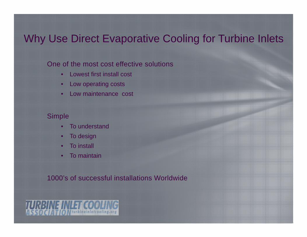
Direct Evaporative Turbine Inlet Cooling (TIC) provides a cost-effective, energy-efficient, and environmentally beneficial means to enhance power generation capacity and efficiency of combustion/gas turbines during hot weather.
Why Use Direct Evaporative Cooling for Turbine Inlets
How Direct Evaporative Cooling Works
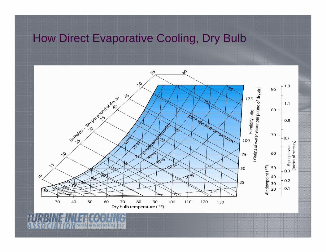
Psychometric Chart
How Direct Evaporative Cooling Works, Dry Bulb
How Direct Evaporative Cooling, Dry Bulb
How Direct Evaporative Cooling Works, Wet Bulb
How Direct Evaporative Cooling Works, Wet Bulb
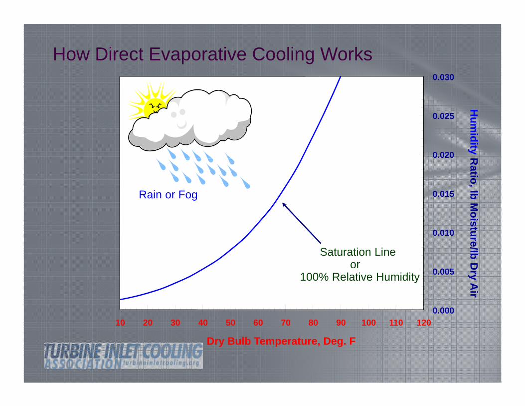
How Direct Evaporative Cooling Works
10 20 30 40 50 60 70 80 90 100 110 120
Dry Bulb Temperature, Deg. F
0.000
0.005
0.010
0.015
0.020
0.025
0.030
Hum
idityR
atio, lb Moisture/lb D
ry Air
Rain or Fog
Saturation Line or
100% Relative Humidity
Moisture Content in Air
.022
.011
.0044
.0022
FOUR EQUAL SIZE CONTAINERS AT 80FWILL HAVE DIFFERENT MOISTURE CONTENTSAT DIFFERENT RELATIVE HUMIDITIES
20% RH 10% RH
W=.022
100% RH 50% RH
W=.011
W=.0044
10 20 30 40 50 60 70 80 90 100 110 120
Dry Bulb Temperature, Deg. F
0.000
0.005
0.010
0.015
0.020
0.025
0.030
Hum
idityR
atio, lb Moisture/lb D
ry Air
W=.0022
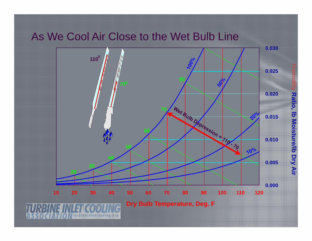
As We Cool Air Close to the Wet Bulb Line
10 20 30 40 50 60 70 80 90 100 110 120
Dry Bulb Temperature, Deg. F
0.000
0.005
0.010
0.015
0.020
0.025
0.030
Hum
idityR
atio, lb Moisture/lb D
ry Air20
3040
50
60
80
70
700
1100
10 20 30 40 50 60 70 80 90 100 110 120
Dry Bulb Temperature, Deg. F
0.000
0.005
0.010
0.015
0.020
0.025
0.030
Hum
idityR
atio, lb Moisture/lb D
ry Air
2030
40
50
60
80
7078110
Direct Evaporative Cooling of an Airstream
Direct Evaporative Cooling of an Airstream
10 20 30 40 50 60 70 80 90 100 110 1200.000
0.005
0.010
0.015
0.020
0.025
0.030
2030
40
50
60
80
70
74110
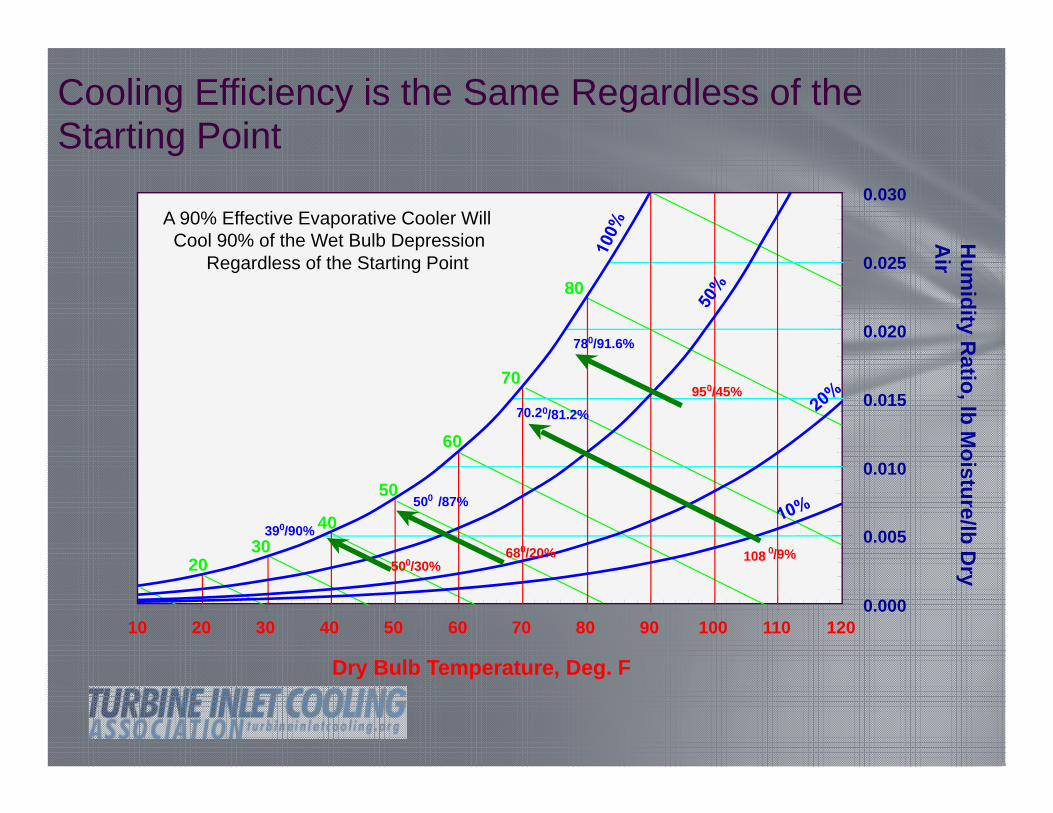
Cooling Efficiency is the Same Regardless of the Starting Point
10 20 30 40 50 60 70 80 90 100 110 120
Dry Bulb Temperature, Deg. F
0.000
0.005
0.010
0.015
0.020
0.025
0.030
Hum
idity Ratio, lb M
oisture/lb Dry
Air
2030
40
50
60
80
70
780/91.6%
950/45%
108 0/9%
70.20/81.2%
390/90%680/20%
500 /87%
500/30%
A 90% Effective Evaporative Cooler Will Cool 90% of the Wet Bulb Depression
Regardless of the Starting Point
As the Day Temp Heats Up
Shreveport, LA, July 18-31, 1993Dry-Bulb, Wet-Bulb & Relative Humidity
40
50
60
70
80
90
100Temperature, F
3230
40
50
60
70
80
90
100Relative Humidity, %
RELATIVEHUMIDITY
WET BULB
DRY BULB
18 19 20 21 22 23 24 25 26 27 28 29 30 31Date in July
30
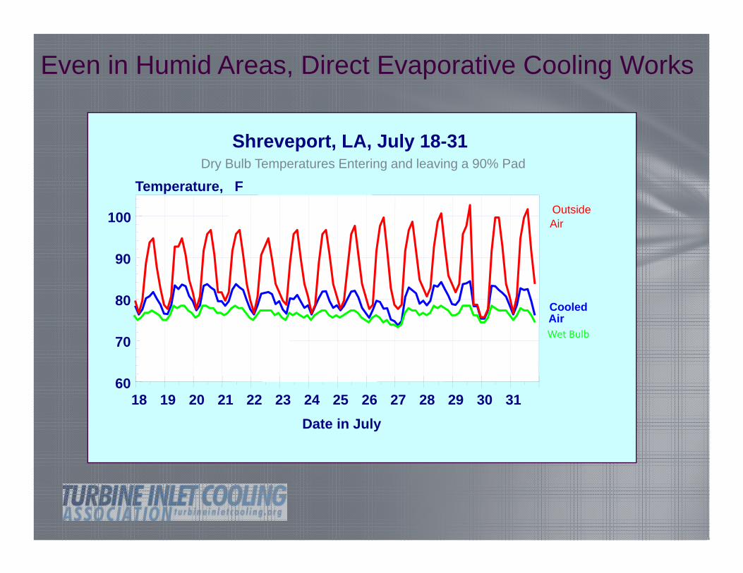
Even in Humid Areas, Direct Evaporative Cooling Works
18 19 20 21 22 23 24 25 26 27 28 29 30 31 32Date in July
60
70
80
90
100
Temperature, F
Shreveport, LA, July 18-31
Cooled Air
Outside Air
Dry Bulb Temperatures Entering and leaving a 90% Pad
Wet Bulb
Tampa Florida, Month of July
60
65
70
75
80
85
90
95
100
Day of Month
DEG
REE
S F
Outdoor Temperature
Cooled Air Temperature
Looking at Tampa Florida
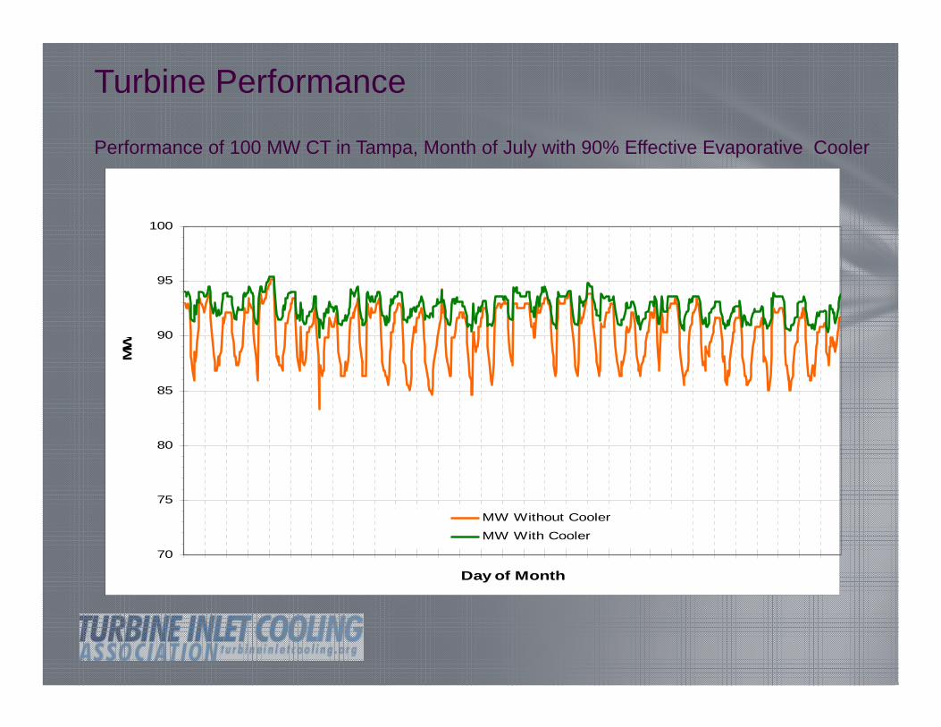
Turbine Performance
70
75
80
85
90
95
100
Day of Month
MW
MW Without Cooler
MW With Cooler
Performance of 100 MW CT in Tampa, Month of July with 90% Effective Evaporative Cooler
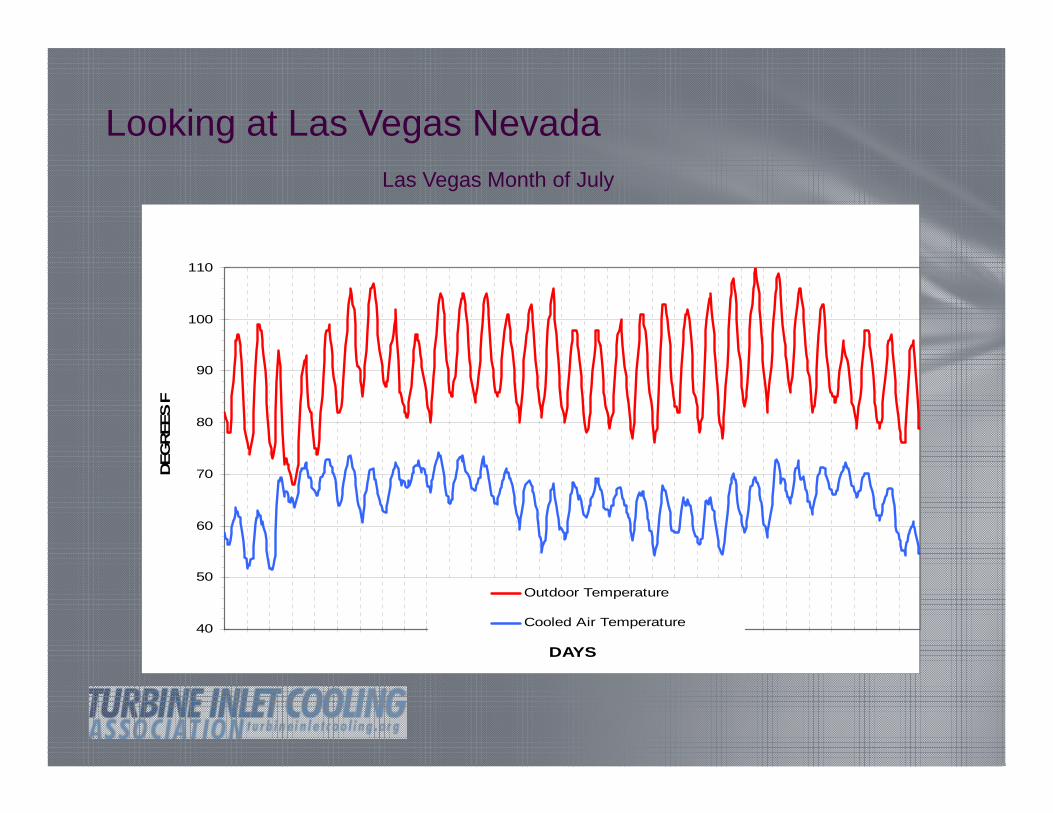
Looking at Las Vegas Nevada
40
50
60
70
80
90
100
110
DAYS
DEG
REE
S F
Outdoor Temperature
Cooled Air Temperature
Las Vegas Month of July
Turbine Performance
65
70
75
80
85
90
95
100
105
110
115
Day of Month
MW
MW Without Cooler
MW With Cooler
Performance of 100 MW CT in Las Vegas, Month of July with 90% Effective Evaporative Cooler
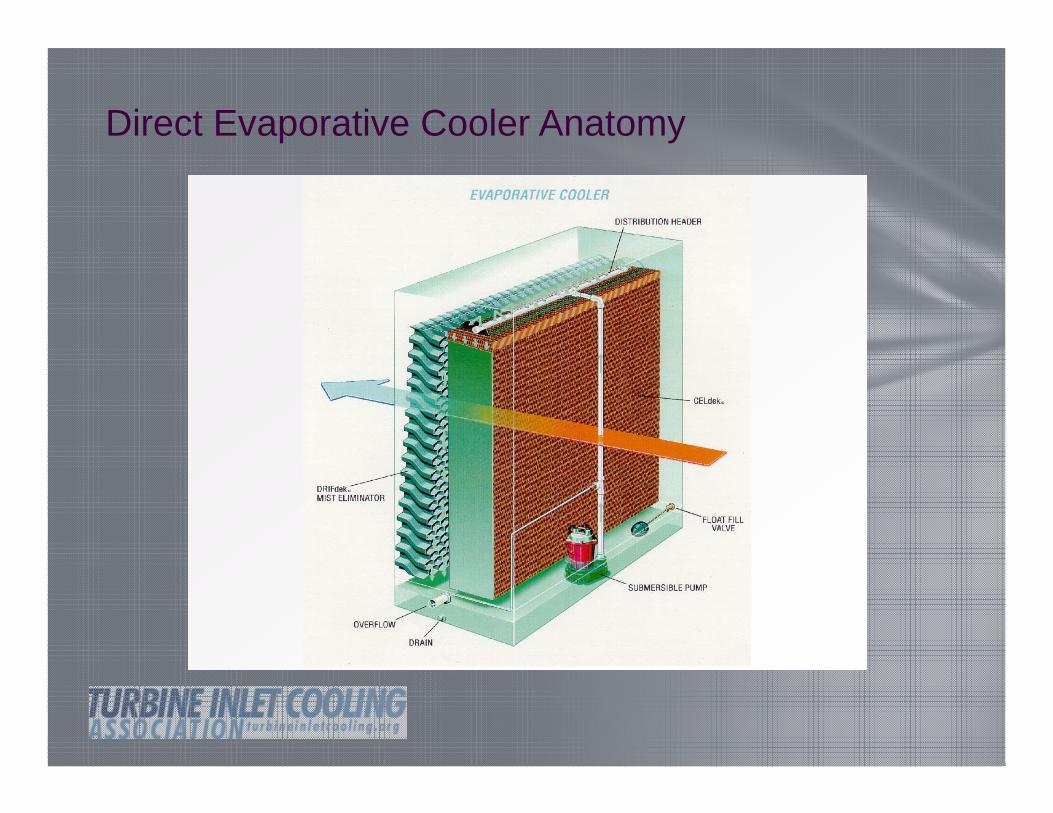
Direct Evaporative Cooler Anatomy
Construction & Examples
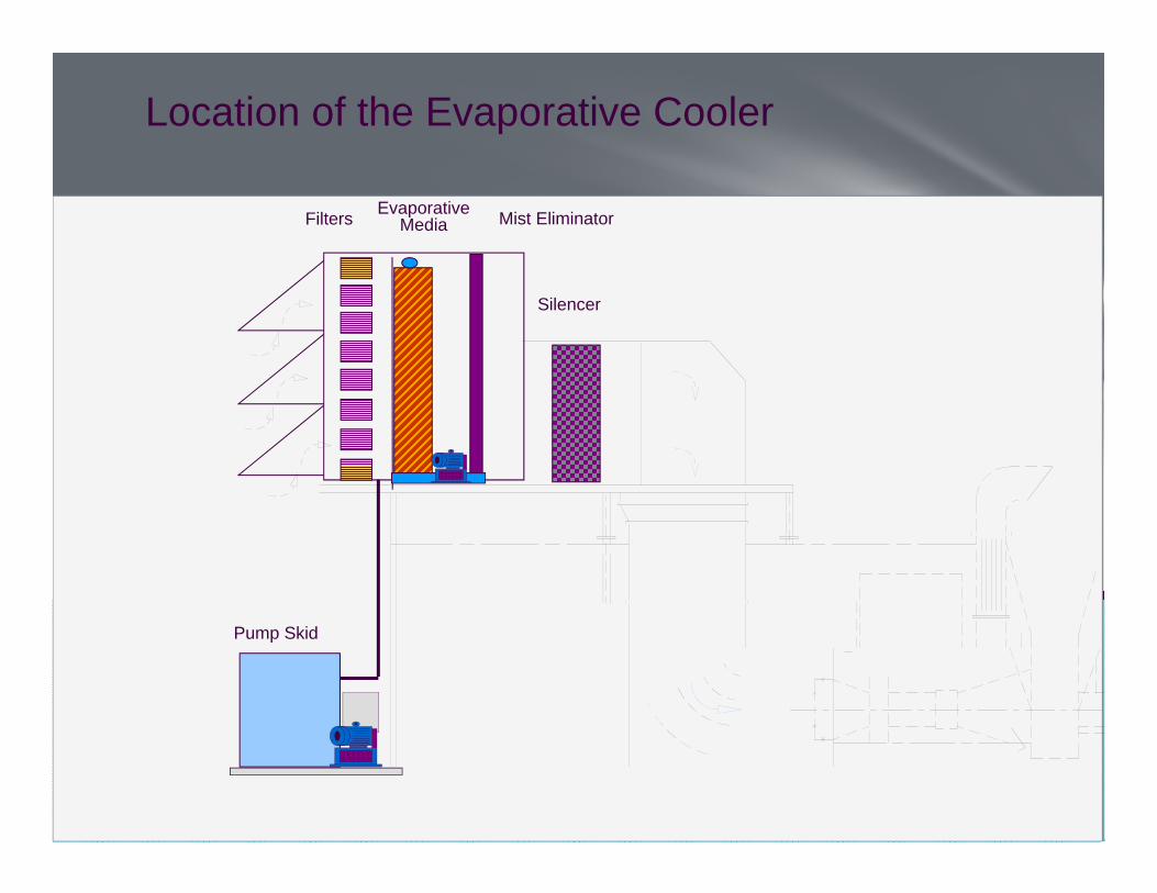
Location of the Evaporative Cooler
Filters Mist EliminatorEvaporative Media
Pump Skid
Silencer
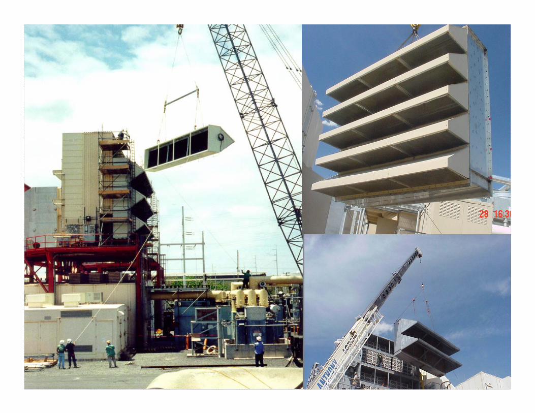
Examples
Webinar Series for Turbine Inlet Cooling Technologies
Webinar Series for Turbine Inlet Cooling Technologies
Examples
Media Upstream of Filters
Media should have edge coat treatment
Filters should be tolerant to higher RH
FiltersMist EliminatorEvaporative
Media
Silencers
Pump
Examples
Design & Construction Considerations
•Face velocity
•Materials of construction
•Material gauge
•Media type
•Water source
•Valve function and locations
•Drains and overflows
•Air bypass
•Sump water management
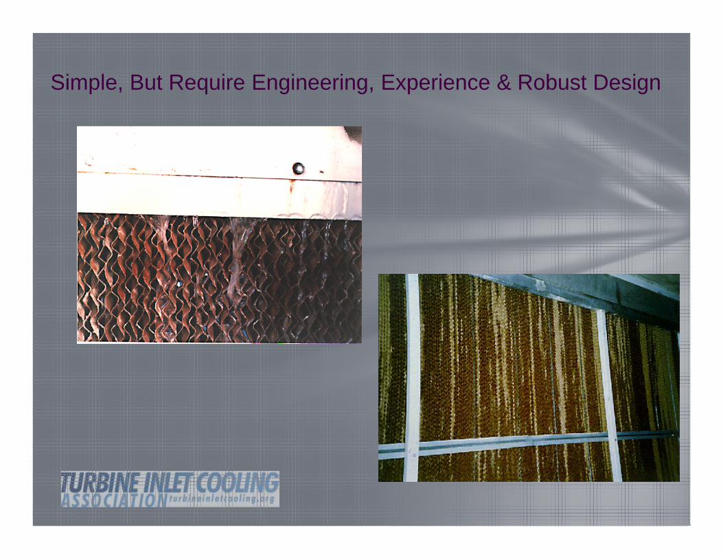
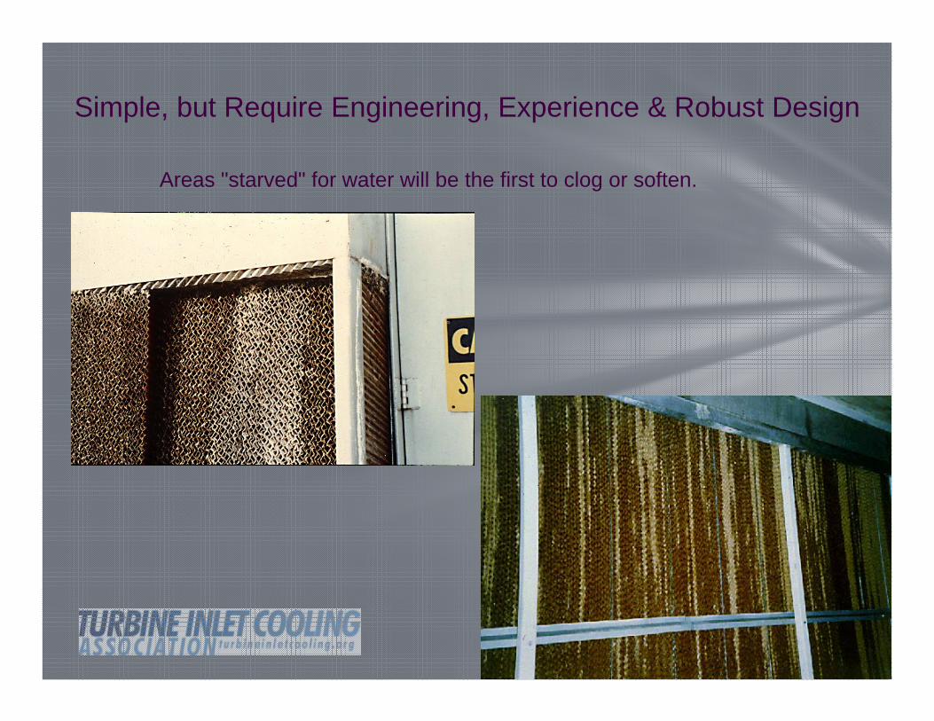
Simple, but Require Engineering, Experience & Robust Design
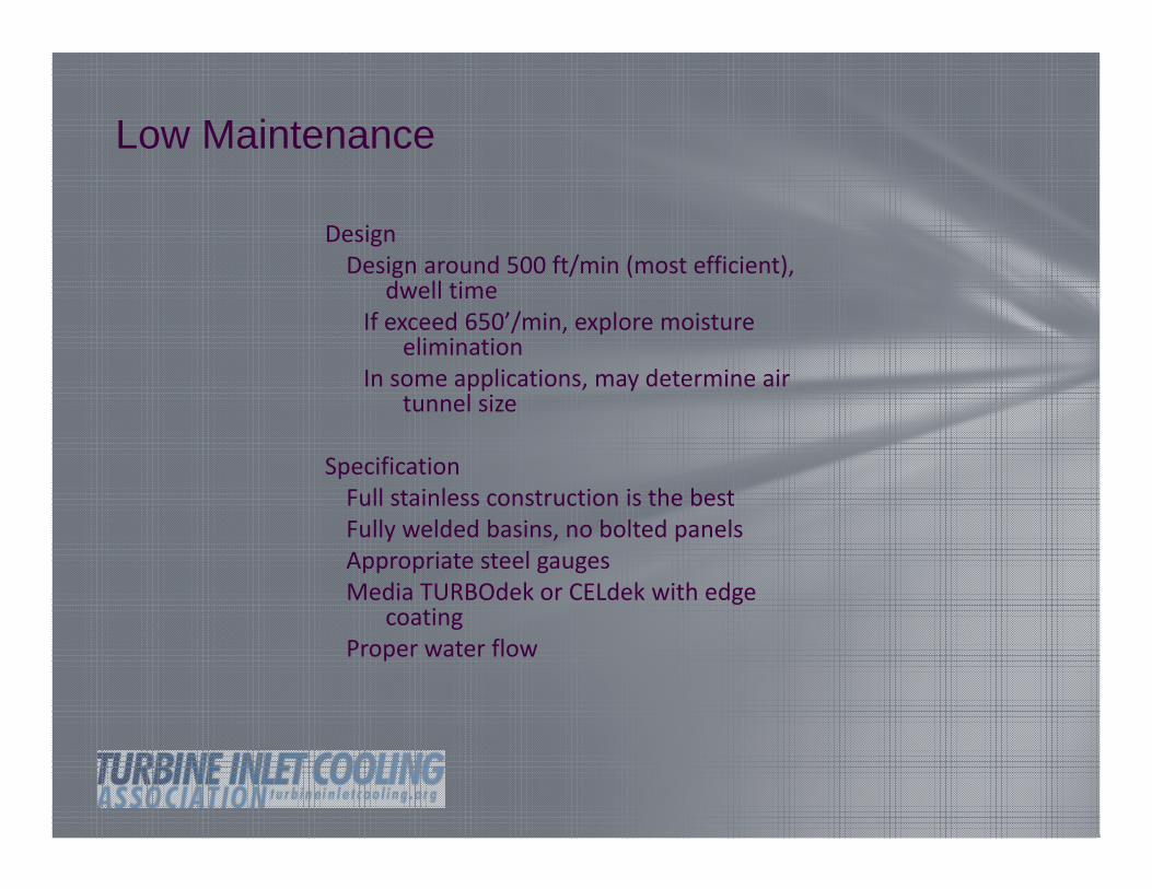
Design Design around 500 ft/min (most efficient), dwell timeIf exceed 650’/min, explore moisture eliminationIn some applications, may determine air tunnel size
SpecificationFull stainless construction is the bestFully welded basins, no bolted panelsAppropriate steel gaugesMedia TURBOdek or CELdek with edge coatingProper water flow
Simple, but Require Engineering, Experience & Robust Design
Simple, But Require Engineering, Experience & Robust Design
Media is the heart of Evaporative Cooling
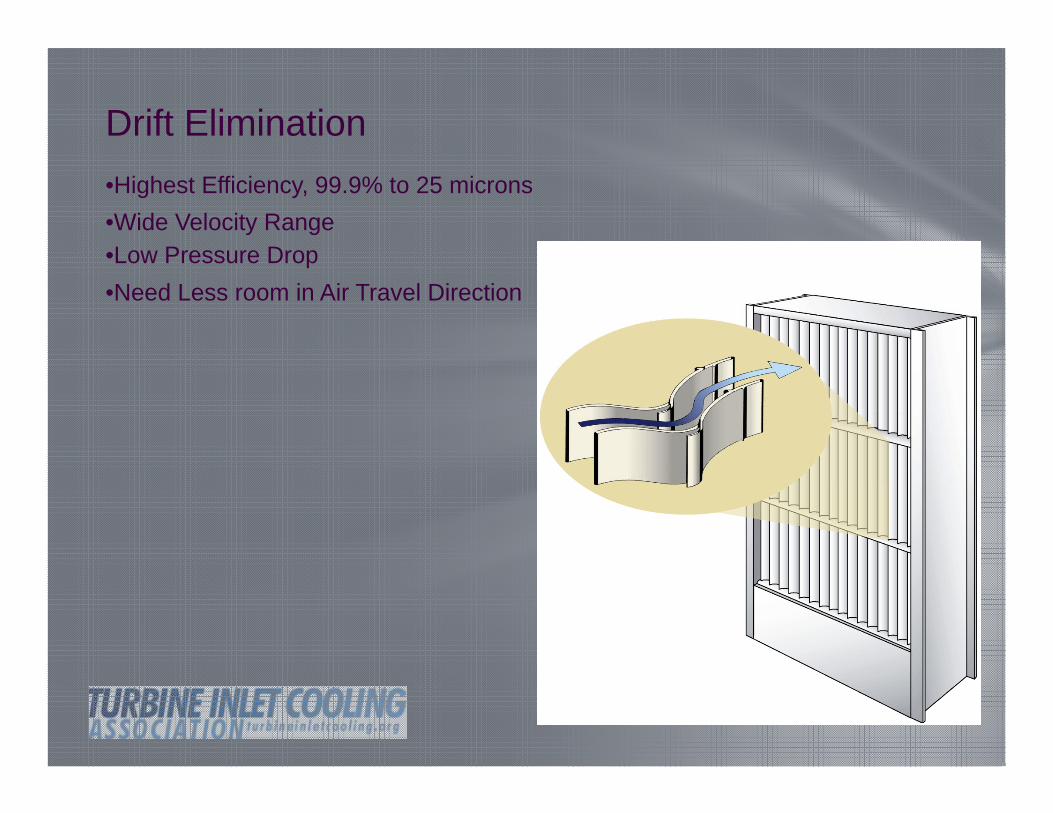
Drift Elimination
• 99.9% down to 50 microns
Drift Elimination•Highest Efficiency, 99.9% to 25 microns•Wide Velocity Range•Low Pressure Drop•Need Less room in Air Travel Direction
Simple, But Require Engineering, Experience & Robust Design
Simple, but Require Engineering, Experience & Robust Design
Areas "starved" for water will be the first to clog or soften.
Simple, but Require Engineering, Experience & Robust Design
Air follows the path of least resistance, think teenagers
Simple but Requires Engineering, Experience & Robust Design
Water Quality & Management
Continuous bleed / and or flush and dump used for scale control
• Scale inhibitors not recommended
• Bleed is major method of control
• Biocides not recommended, no oxidizing biocides allowed
• Corrosion inhibitors not recommended
• ALL SS and plastic construction
• Straight RO water is not recommended but a blend is okay
Water Quality and Management
• Chemicals dry out on the media each time the water is turned off, causing the chemicals to loose their effectiveness
• Some chemicals are corrosive and will harm pads and turbine components.
• Some chemicals contribute to microbial growth.
• Many chemicals cause environmental problems.
• Those who use chemicals often feel they can neglect other maintenance requirements
Reverse Osmosis High CostHigh Maintenance costMinimal Bleed off
Demineralization High CostRequires handling chemicalsMinimal Bleed off
Zeolite Softening Changes Calcium Carbonate to Sodium CarbonateDoes not remove SilicaRequires bleed-off
Acid Addition Typically use concentrated sulphuric acidMakes Calcium and Magnesium less soluble Requires continuous injection of acidDangerous to handle/ can add too much acidRequires bleed-off
Crystal Modifiers Requires continuous injection of chemicalLeaves a soft sludge residue that can blow downstream
Sequesterants Require addition of sodium hexametaphosphateEncourages algae growth
Water Quality & Management
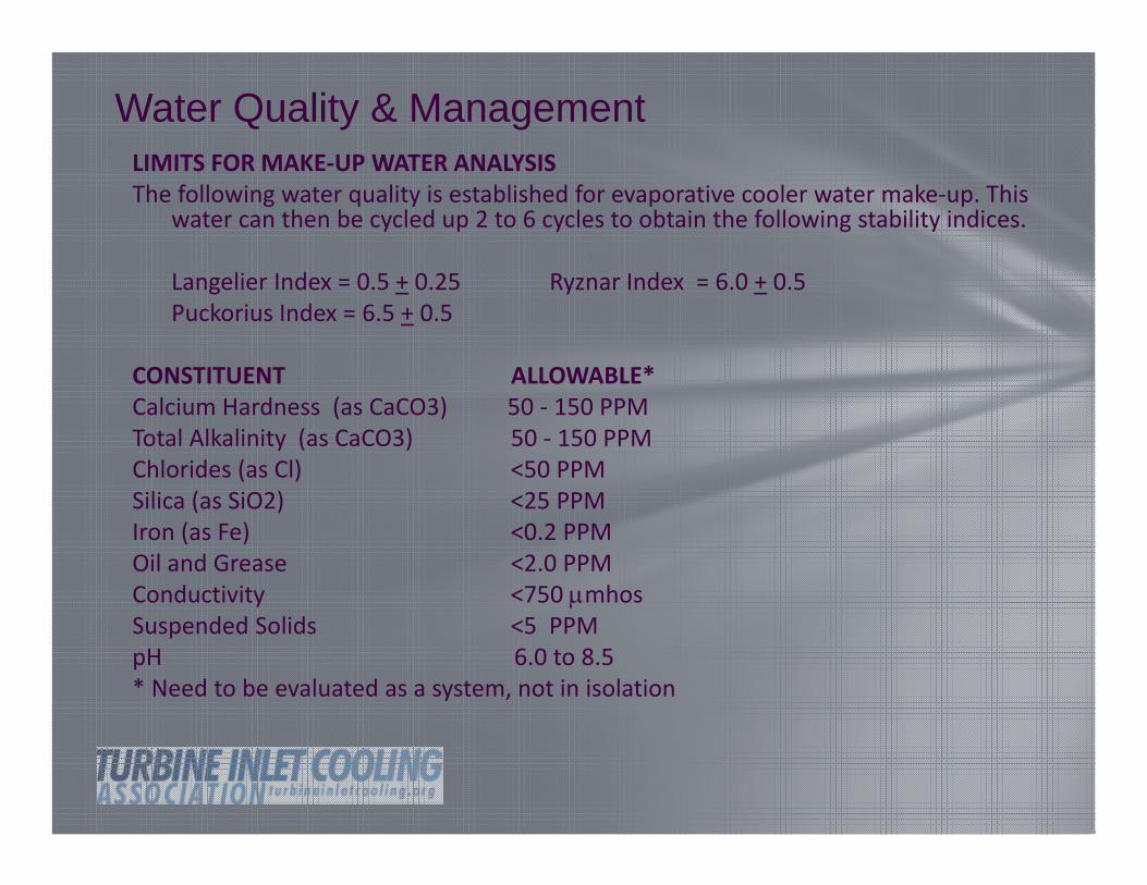
Water Quality & ManagementLIMITS FOR MAKE‐UP WATER ANALYSISThe following water quality is established for evaporative cooler water make‐up. This
water can then be cycled up 2 to 6 cycles to obtain the following stability indices.
Langelier Index = 0.5 + 0.25 Ryznar Index = 6.0 + 0.5Puckorius Index = 6.5 + 0.5
CONSTITUENT ALLOWABLE*Calcium Hardness (as CaCO3) 50 ‐ 150 PPMTotal Alkalinity (as CaCO3) 50 ‐ 150 PPMChlorides (as Cl) <50 PPMSilica (as SiO2) <25 PPMIron (as Fe) <0.2 PPMOil and Grease <2.0 PPMConductivity <750 mhosSuspended Solids <5 PPMpH 6.0 to 8.5* Need to be evaluated as a system, not in isolation
Water Quality & Management
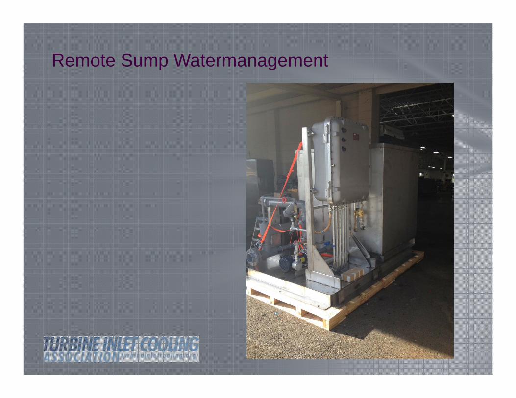
Remote Sump Watermanagement
Remote Sump Water Management
Water Quality & Management
• We want you system to operate as designed and for your Media Engine to last as long as possible!!!
• PLEASE use Munters experience and chemists to analyze your sites water more often than not……..we make it easy!
Water is the life of our system and we recommend a full water analysis. Project can submit a written water report via the local water municipality or through a water sample. Please submit:
Report to Dan Schumacher [email protected] Sample to Southern Analytical Laboratories, Inc