47
BIS C-6026 EtherNet/IP Technical Description, User‘s Manual EN www.balluff.com
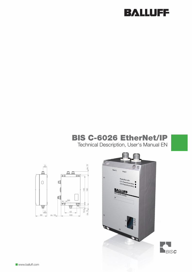
BIS C-6026 EtherNet/IPTechnical Description, User‘s Manual EN
www.balluff.com

2
BIS C-6026 EtherNet/IPProcessor
3www.balluff.com
BIS C-6026 EtherNet/IPProcessor
8
9
4
7
6
5
3
2
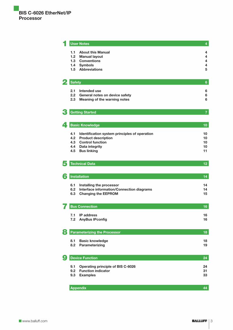
User Notes 4
1.1 About this Manual 41.2 Manual layout 41.3 Conventions 41.4 Symbols 41.5 Abbreviations 5
Safety 6
2.1 Intended use 62.2 General notes on device safety 62.3 Meaning of the warning notes 6
Getting Started 7
Basic Knowledge 10
4.1 Identification system principles of operation 104.2 Product description 104.3 Control function 104.4 Data integrity 104.5 Bus linking 11
Technical Data 12
Installation 14
6.1 Installing the processor 146.2 Interface information/Connection diagrams 146.3 Changing the EEPROM 15
Bus Connection 16
7.1 IP address 167.2 AnyBus IPconfig 16
Parameterizing the Processor 18
8.1 Basic knowledge 188.2 Parameterizing 19
Device Function 24
9.1 Operating principle of BIS C-6026 249.2 Function indicator 319.3 Examples 33
Appendix 44
1
4
BIS C-6026 EtherNet/IPProcessor
This manual describes the processor for the BIS C-6026 identification system and guides you through startup for immediate operation.
The manual is designed so that each section builds on the previous sections.Kapitel 2: Basic information regarding safety.Kapitel 3: The main steps in installing the identification system.Kapitel 4: An introduction into the material.Kapitel 5: Technical data for the processor.Kapitel 6: Mechanical and electrical connections.Kapitel 7: Logging the processor on to the network.Kapitel 8: User-defined settings for the processor.Kapitel 9: How the processor and host system work.
The following conventions are used in this manual.
Enumerations are represented as a list with bullet points.Entry 1,Entry 2.
Action instructions are indicated by a preceding triangle. The result of an action is indicated by an arrow.
Action instruction 1.Result of action.
Action instruction 2.
of numbers:Decimal numbers are represented without additional description (e.g. 123),hexadecimal numbers are represented by appending the abbreviation hex (e.g. 00hex).
of parameters:Parameters are written in italics, e.g. (CRC_16).
Directory paths:Paths in which data are or will be saved/stored are represented in small caps(e.g. PROJECT:\DATA TYPES\USERDEFINED).
Cross-references indicate where additional information on the topic can be found(see Technical Data starting p 12).
AttentionThis symbol indicates a safety advisory which must be observed.
Note, tipThis symbol indicates general notes.
––
�
⇒
�
––
1.1 About this Manual
1.2 Manual layout
1.3 ConventionsEnumerations
Actions
Notation
Cross-references
1.4 Symbols
User Notes1
5www.balluff.com
BIS C-6026 EtherNet/IPProcessor
User Notes1
ARP Address Resolution PredocolBIS Balluff Identification SystemCIP Common Industrial PredocolCRC Cyclic Redundancy CodeDHCP Dynamic Host Configuration PredocolEDS Electronic Data Sheet EEPROM Electrical Erasable and Programmable ROMEMV Electromagnetic CompatibilityMAC-ID Media Access Control IdentifierODVA Open DeviceNet Vendor AssociationPC Personal ComputerRPI Requested Packed IntervalPLC Programmable Logic Controller
1.5 Abbreviations
6
BIS C-6026 EtherNet/IPProcessor
The BIS C-6026 processor is a component of the BIS C identification system. Within the identi-fication system it is used for linking to a host computer (PLC, PC). It is intended only for use only in this way and in an industrial environment complying with Class A of the EMC Law. This description applies to processors in series BIS C-6026-034-….
Installation and startupInstallation and startup are to be carried out only by trained specialists. The manufacturer revokes the right to any warranty or liability claims resulting from unauthorized modifications or improper use. When connecting the processor to an external controller, be sure to observe proper polarity for all connections including the power supply (see section „Installation“ on page 14). The processor must be operated only using approved power supplies (see section „Technical Data“ on page 12).
Operation and testingIt is the responsibility of the operator to ensure that the locally applicable safety regulations are maintained. In case of defects and faults in the identification system which cannot be remedied, take it out of operation and predect against unauthorized use.
Attention!The pictogram used with the word “Attention” warns of a possibly hazardous situation for the health of persons or equipment damage. Disregarding these warnings may result in personal injury or equipment damage.
Always observe the instructions given for avoiding this hazard. �
2.1 Intendeduse
2.2 General notes on device safety
2.3 Meaning of the warning notes
Safety2
7www.balluff.com
BIS C-6026 EtherNet/IPProcessor
Getting Started3
Mechanical connection
Electrical connection
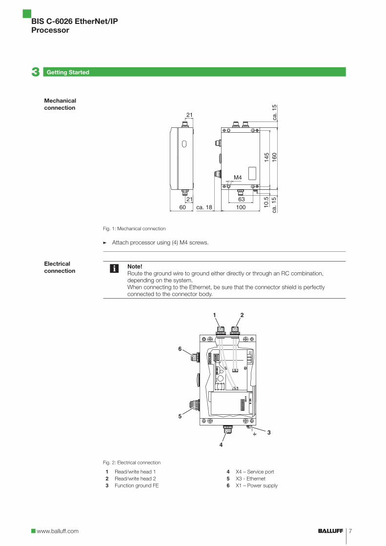
Fig. 1: Mechanical connection
Attach processor using (4) M4 screws.
Note!Route the ground wire to ground either directly or through an RC combination, depending on the system. When connecting to the Ethernet, be sure that the connector shield is perfectly connected to the connector body.
Fig. 2: Electrical connection
1 Read/write head 12 Read/write head 23 Function ground FE
4 X4 – Service port5 X3 - Ethernet6 X1 – Power supply
�
8
BIS C-6026 EtherNet/IPProcessor
Bus connection
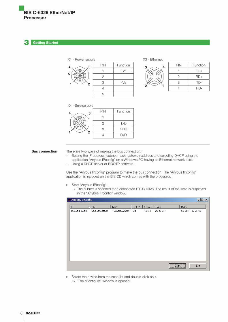
X1 - Power supply X3 - Ethernet
PIN Function PIN Function
1 +VS 1 TD+
2 2 RD+
3 -VS 3 TD-
4 4 RD-
5
X4 - Service port
PIN Function
1
2 TxD
3 GND
4 RxD
There are two ways of making the bus connection:Setting the IP address, subnet mask, gateway address and selecting DHCP using the application “Anybus IPconfig” on a Windows PC having an Ethernet network card.Using a DHCP server or BOOTP software.
Use the “Anybus IPconfig” program to make the bus connection. The “Anybus IPconfig” application is included on the BIS CD which comes with the processor.
Start “Anybus IPconfig“.The subnet is scanned for a connected BIS C-6026. The result of the scan is displayed in the “Anybus IPconfig” window.
Select the device from the scan list and double-click on it. The “Configure” window is opened.
–
–
�
⇒
�
⇒
Getting Started3
9www.balluff.com
BIS C-6026 EtherNet/IPProcessor
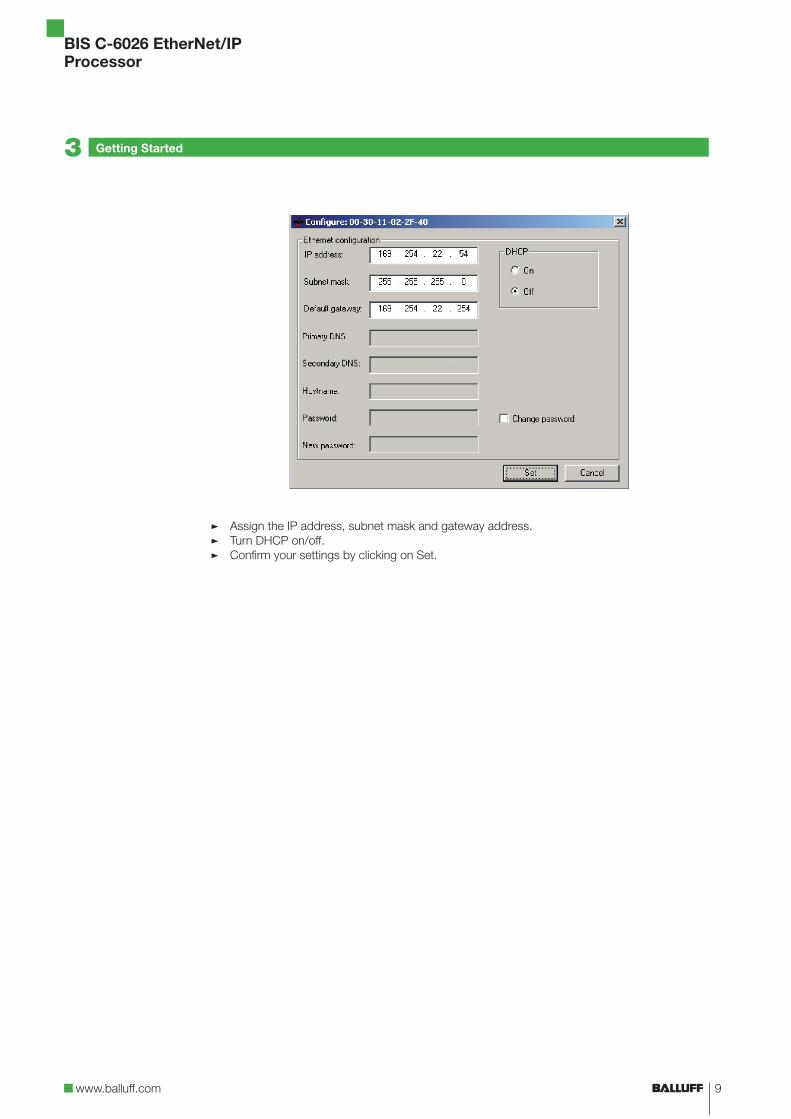
Assign the IP address, subnet mask and gateway address.Turn DHCP on/off.Confirm your settings by clicking on Set.
�
�
�
Getting Started3
10
BIS C-6026 EtherNet/IPProcessor
Basic Knowledge4
4.1 Identification system principles of operation
4.2 Product description
4.3 Control function
4.4 Data integrity
The BIS C identification system belongs to the category of non-contact systems having a read and write function. This enables you to not only read data contained in the data carriers, but also to write new data to them at any point in the process.
The main components of the BIS C identification system are:Processor,read/write heads,data carriers.
The main areas of application are:In production for controlling material flow (e.g. for variant-specific processes, workpiece transport using conveying systems, for collecting safety-related data), in tool coding and monitoring,in process equipment organization,in inventory systems for monitoring inventory movements,in transport and conveying technology, in waste management for quantity-dependent logging.
BIS C-6026 processor:Metal enclosure,round connectors for making plug connections,capacity for two read/write heads,read/write heads are suitable for both dynamic and static operation,processor provides power for system components,
Carrier signal from the read/write heads provides power for the data carrier.
The processor represents the link between the data carrier and the host control system. It manages two-way data transfer between the data carrier and read/write head and provides a buffer storage function. The processor writes data from the host signal to the data carrier through the read/write head, or reads data from the data carrier and makes the data available to the host system.
Host systems may be:A control computer (e.g. industrial PC),a PLC.
Dual bit-header:In order to ensure consistency of the transmitted data, the control bits in the first and last byte (bit-header) of the data buffer for each read/write head are sent and compared. If the two bit-headers are identical, then the data were fully updated and may be accepted. This means that the data for each read/write head are only valid if both bit-headers are identical. The host system must therefore also compare the bits in the bit-headers.
To ensure data integrity the data transfer between data carrier and processor must be monitored using a check procedure. The factory default setting in the processor is for double read with compare. A CRC_16 check may however be selected as an alternative. In CRC_16 checking a check code is written to the data carrier, which enables checking the data for validity at any time. Which procedure is used depends on how you are using the identification system.
–––
–
–––––
–––––
––
11www.balluff.com
BIS C-6026 EtherNet/IPProcessor
Note!Mixed operation of the two check procedures is not possible!
The following table provides an overview of the advantages of each respective check procedure.
CRC_16 data check Double read
Data integrity even during the non-active phase (data carrier outside the read/write head)
No user data bytes are lost for storing a check code.
Shorter read time – page is read just once Shorter read time – no check code is written
The processor and host system communicate using EtherNet/IP predocol.
EtherNet/IP is an industrial network standard. The IP in EtherNet/IP stands for “Industrial Pro-tocol”. EtherNet/IP uses the open communications predocol “Common Industrial Predocol” (CIP) on the application layer (as per the ISO/OSI reference model).EtherNet/IP is supported by the network organization “Open DeviceNet Vendor Association”.
Use of a switch in full-duplex mode is necessary for collision-free data exchange.
Basic Knowledge4
4.5 Bus connection
12
BIS C-6026 EtherNet/IPProcessor
Technical Data5
Dimensions
Mechanical data
Electrical data
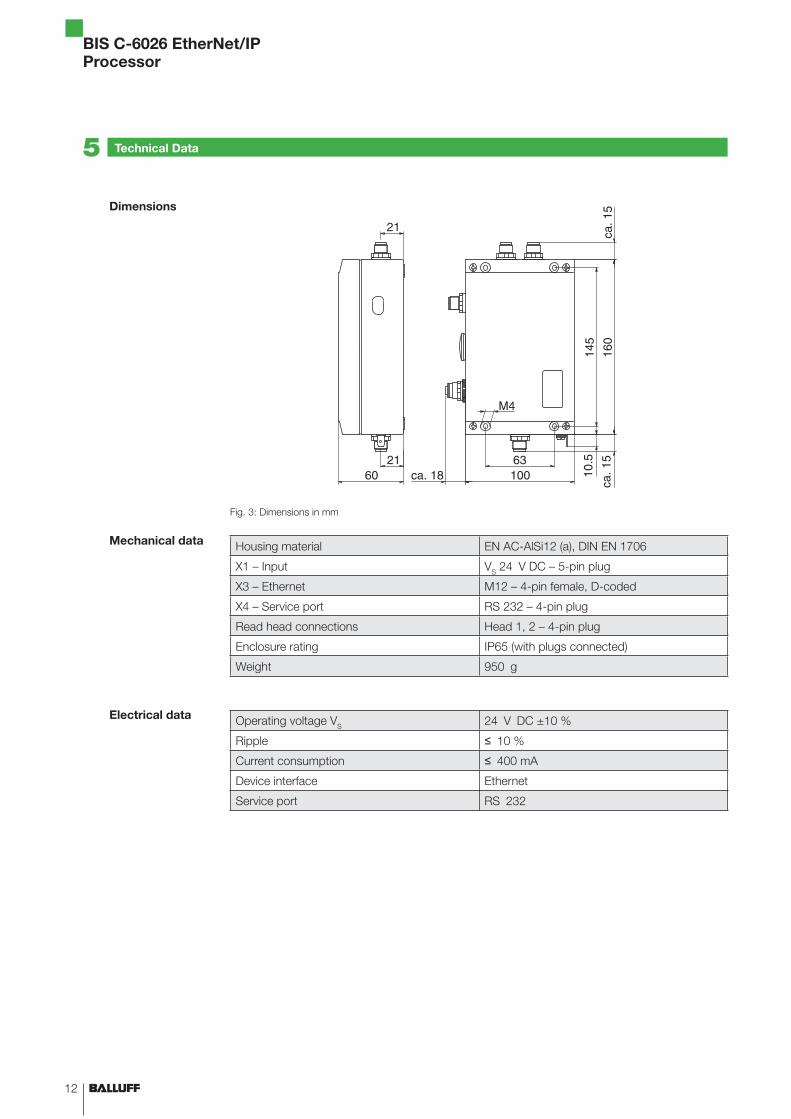
Fig. 3: Dimensions in mm
Housing material EN AC-AlSi12 (a), DIN EN 1706
X1 – Input VS 24 V DC – 5-pin plug
X3 – Ethernet M12 – 4-pin female, D-coded
X4 – Service port RS 232 – 4-pin plug
Read head connections Head 1, 2 – 4-pin plug
Enclosure rating IP65 (with plugs connected)
Weight 950 g
Operating voltage VS 24 V DC ±10 %
Ripple ≤ 10 %
Current consumption ≤ 400 mA
Device interface Ethernet
Service port RS 232
13www.balluff.com
BIS C-6026 EtherNet/IPProcessor
Ambient temperature 0 °C … 60 °C
EMV
EN 61000-4-2/3/4/5/6EN 55011
––
Severity level 4A/3A/3A/1B/3AGr. 1, Cl. A
––
Shock/Vibration EN 60068 Part 2-6/27/29/64/32
BIS operating states Ready CT1 Present/operating CT2 Present/operating
Green LED Green/yellow LEDGreen/yellow LED
Status EtherNet/IP Data Rate (DR)Module Status (MS)Network Status (NS)Link/Activity (L/A)
LEDLEDLEDLED
Operating conditions
Function indicators
Technical Data5
14
BIS C-6026 EtherNet/IPProcessor
Installation6
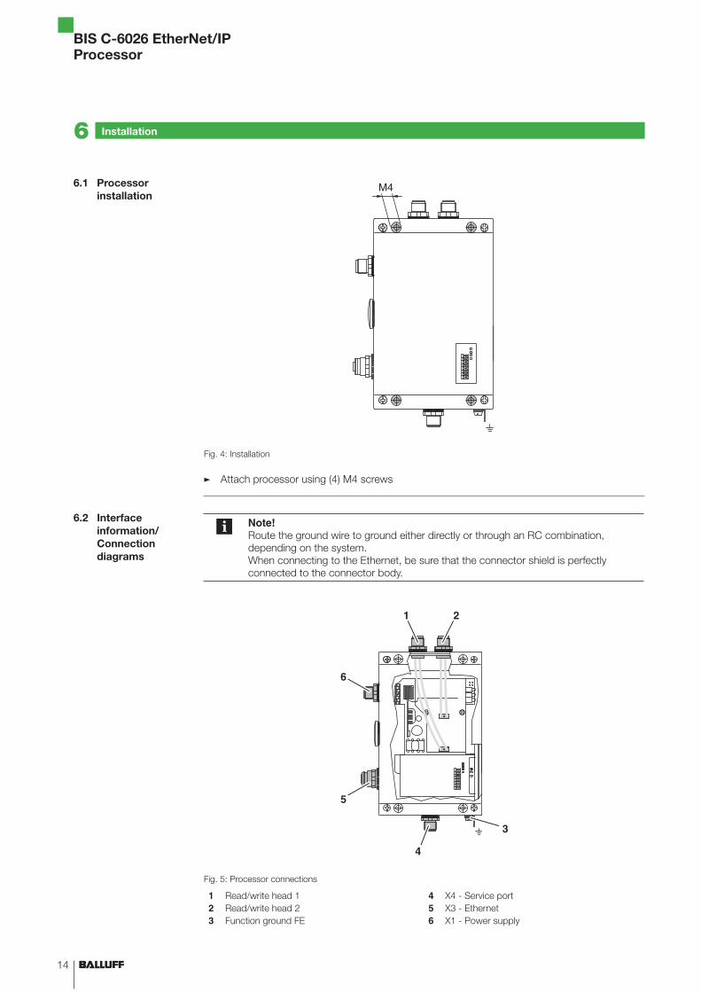
6.1 Processor installation
6.2 Interface information/Connection diagrams
Fig. 4: Installation
Attach processor using (4) M4 screws
Note!Route the ground wire to ground either directly or through an RC combination, depending on the system. When connecting to the Ethernet, be sure that the connector shield is perfectly connected to the connector body.
Fig. 5: Processor connections
1 Read/write head 12 Read/write head 23 Function ground FE
4 X4 - Service port5 X3 - Ethernet6 X1 - Power supply
�
15www.balluff.com
BIS C-6026 EtherNet/IPProcessor
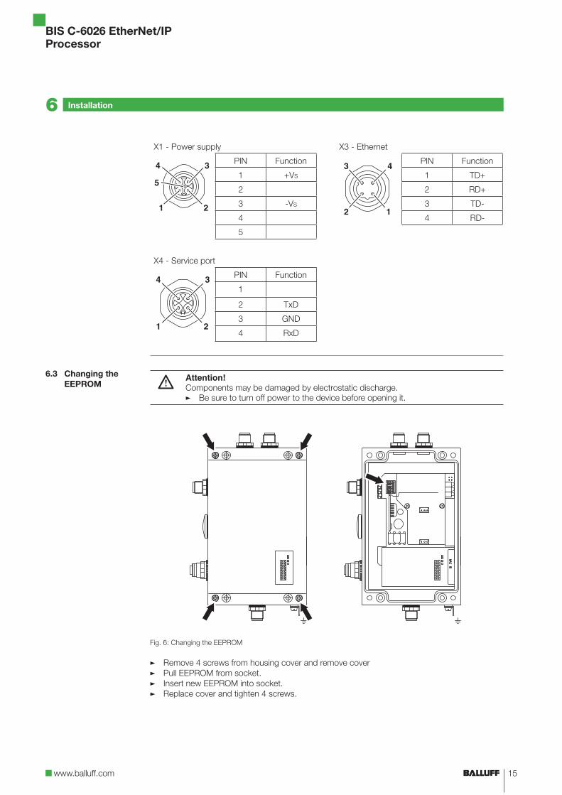
X1 - Power supply X3 - Ethernet
PIN Function PIN Function
1 +VS 1 TD+
2 2 RD+
3 -VS 3 TD-
4 4 RD-
5
X4 - Service port
PIN Function
1
2 TxD
3 GND
4 RxD
Attention!Components may be damaged by electrostatic discharge.
Be sure to turn off power to the device before opening it.�
Fig. 6: Changing the EEPROM
Remove 4 screws from housing cover and remove coverPull EEPROM from socket.Insert new EEPROM into socket.Replace cover and tighten 4 screws.
�
�
�
�
Installation6
6.3 Changing the EEPROM
16
BIS C-6026 EtherNet/IPProcessor
Bus Connection7
7.1 IP address
DHCP
7.2 AnyBus IPconfig
The processor and host system communicate using EtherNet/IP predocol. Assigning a unique IP address associates the processor with a network.
The processor can be incorporated into a network in various ways (DHCP, ARP). The MAC address is used as the basis for incorporating into the network. This hardware address is used only one time and uniquely identifies network devices such as the processor.
Dynamic Host Configuration Predocol (DHCP) allows a server to be used for dynamic assigning of an IP address. The hardware can be inserted into the network without having to perform any additional configuration. Only automatic obtaining (MAC address) of the IP address needs to be set.
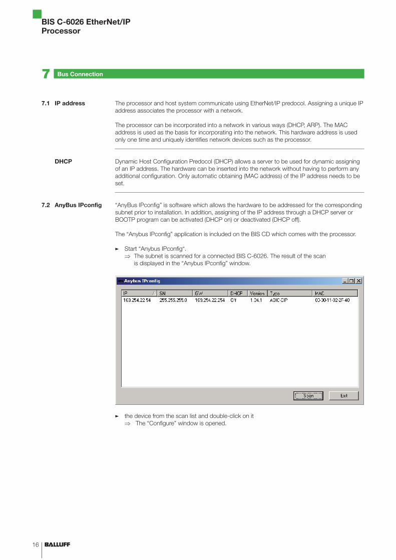
“AnyBus IPconfig” is software which allows the hardware to be addressed for the corresponding subnet prior to installation. In addition, assigning of the IP address through a DHCP server or BOOTP program can be activated (DHCP on) or deactivated (DHCP off).
The “Anybus IPconfig” application is included on the BIS CD which comes with the processor.
Start “Anybus IPconfig“.The subnet is scanned for a connected BIS C-6026. The result of the scan is displayed in the “Anybus IPconfig” window.
the device from the scan list and double-click on it The “Configure” window is opened.
�
⇒
�
⇒
17www.balluff.com
BIS C-6026 EtherNet/IPProcessor
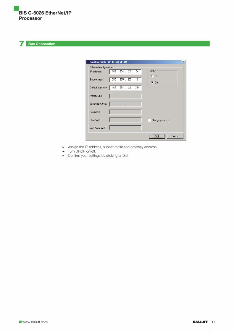
Assign the IP address, subnet mask and gateway address.Turn DHCP on/off.Confirm your settings by clicking on Set.
�
�
�
Bus Connection7
18
BIS C-6026 EtherNet/IPProcessor
Parameterizing the Processor8
8.1 Basic knowledge
CRC check
Simultaneous data transmission
The CRC check is a procedure for determining a test value for data so as to detect errors in transferring data. If CRC check is activated, an error message is output when a CRC error is detected.
InitializingTo be able to use the CRC check, the data carriers must be initialized. The data carriers are initialized in the output buffer using the command 12hex If the data carrier does not contain the correct CRC, then the processor sets an error message in the input buffer (see Example 10 on page 42). As shipped from the factory, data carriers may be immediately written a checksum, since all the data are set to 0.
Error messageIf an error message is the result of a failed write job, then the data carrier must be reinitialized before it can be used again. If an error message is not the result of a failed write job, then one or more of the memory cells in the data carrier are defective. This means the data carrier must be replaced.
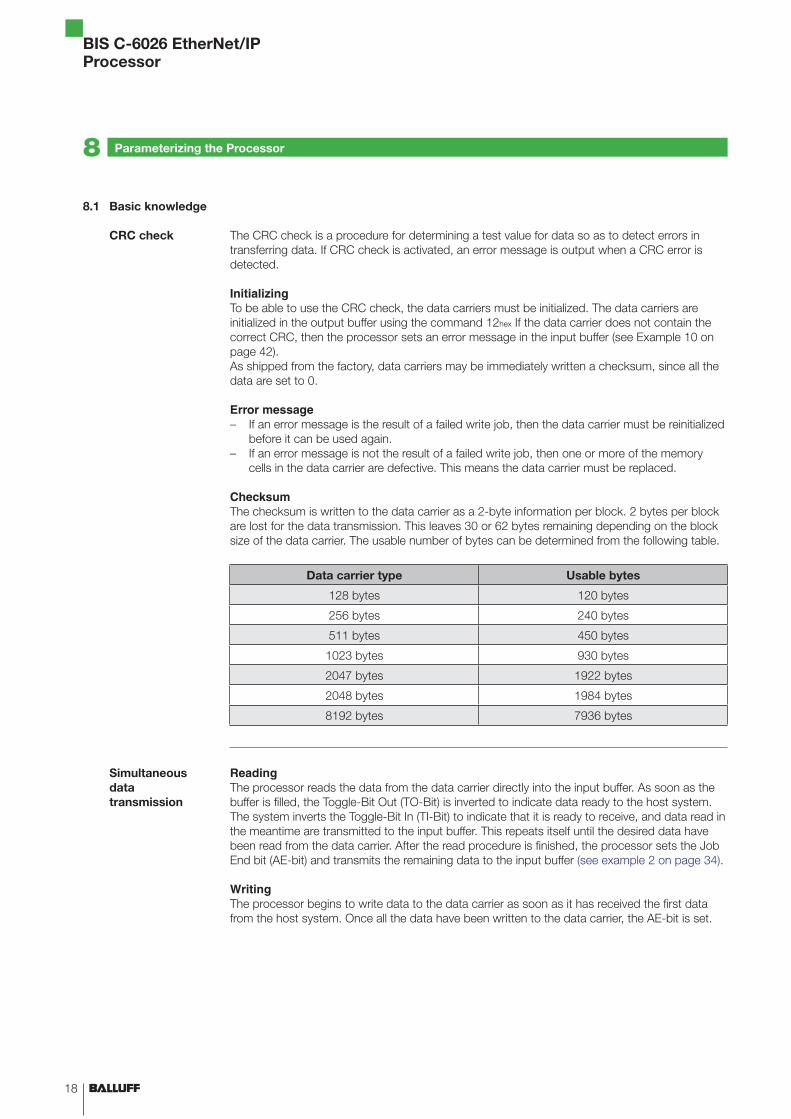
ChecksumThe checksum is written to the data carrier as a 2-byte information per block. 2 bytes per block are lost for the data transmission. This leaves 30 or 62 bytes remaining depending on the block size of the data carrier. The usable number of bytes can be determined from the following table.
Data carrier type Usable bytes
128 bytes 120 bytes
256 bytes 240 bytes
511 bytes 450 bytes
1023 bytes 930 bytes
2047 bytes 1922 bytes
2048 bytes 1984 bytes
8192 bytes 7936 bytes
ReadingThe processor reads the data from the data carrier directly into the input buffer. As soon as the buffer is filled, the Toggle-Bit Out (TO-Bit) is inverted to indicate data ready to the host system. The system inverts the Toggle-Bit In (TI-Bit) to indicate that it is ready to receive, and data read in the meantime are transmitted to the input buffer. This repeats itself until the desired data have been read from the data carrier. After the read procedure is finished, the processor sets the Job End bit (AE-bit) and transmits the remaining data to the input buffer (see example 2 on page 34).
WritingThe processor begins to write data to the data carrier as soon as it has received the first data from the host system. Once all the data have been written to the data carrier, the AE-bit is set.
–
–
19www.balluff.com
BIS C-6026 EtherNet/IPProcessor
As soon as the Dynamic function is activated, the processor accepts the read/write job from the host system and stores it regardless of whether there is a data carrier in the active zone of the read/write head. When a data carrier enters the active zone of the read/write head, the stored job is carried out.
When a data carrier enters the active zone of the read/write head, 14 bytes beginning with Address 00hex are automatically read into the input buffer. No separate read command is necessary. This allows small data amounts stored beginning at Address 00hex to be read faster. If Auto-Read (Extra) is activated, then the 14 bytes starting at a specified address are read from the data carrier into the input buffer and then the Codetag Present bit (CP-bit) is set. The start address is specified using the parameter (Extra_Adr).
There are two different ways to set parameters. Parameterizing from an application program or using the EDS file.
The parameters for operating the processor are stored in the BIS Config Object (class 64hex). Explicit messages are used to access the parameters.
Parameterizing from an application programOne widely used application for Ethernet/IP device parameterizing is the Windows program RSLogix 5000 written for the Logix 5000 controller of Rockwell Automation. An example for device programming is included on the BIS-CD. For additional information see section „Example for parameterizing with application program“ on page 21.
EDS fileThe EDS file contains all the device parameters for the processor. The file is included on the BIS-CD.
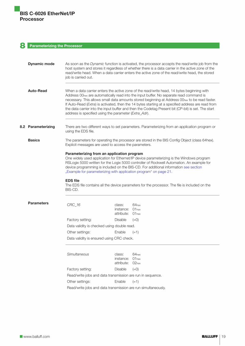
CRC_16 class:instance:attribute:
64hex
01hex
01hex
Factory setting: Disable (=0)
Data validity is checked using double read.
Other settings: Enable (=1)
Data validity is ensured using CRC check.
Simultaneous class:instance:attribute:
64hex
01hex
02hex
Factory setting: Disable (=0)
Read/write jobs and data transmission are run in sequence.
Other settings: Enable (=1)
Read/write jobs and data transmission are run simultaneously.
Dynamic mode
Auto-Read
8.2 Parameterizing
Basics
Parameters
Parameterizing the Processor8
20
BIS C-6026 EtherNet/IPProcessor
Parameterizing the Processor8
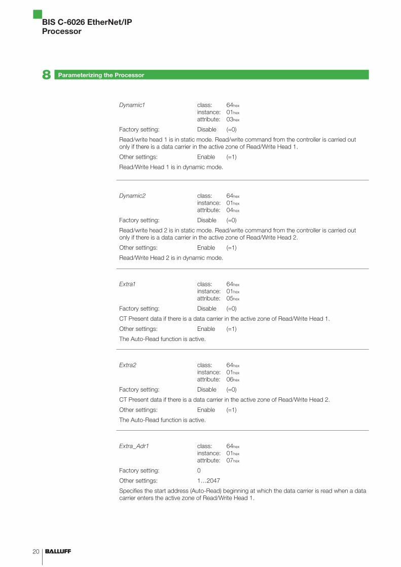
Dynamic1 class:instance:attribute:
64hex
01hex
03hex
Factory setting: Disable (=0)
Read/write head 1 is in static mode. Read/write command from the controller is carried out only if there is a data carrier in the active zone of Read/Write Head 1.
Other settings: Enable (=1)
Read/Write Head 1 is in dynamic mode.
Dynamic2 class:instance:attribute:
64hex
01hex
04hex
Factory setting: Disable (=0)
Read/write head 2 is in static mode. Read/write command from the controller is carried out only if there is a data carrier in the active zone of Read/Write Head 2.
Other settings: Enable (=1)
Read/Write Head 2 is in dynamic mode.
Extra1 class:instance:attribute:
64hex
01hex
05hex
Factory setting: Disable (=0)
CT Present data if there is a data carrier in the active zone of Read/Write Head 1.
Other settings: Enable (=1)
The Auto-Read function is active.
Extra2 class:instance:attribute:
64hex
01hex
06hex
Factory setting: Disable (=0)
CT Present data if there is a data carrier in the active zone of Read/Write Head 2.
Other settings: Enable (=1)
The Auto-Read function is active.
Extra_Adr1 class:instance:attribute:
64hex
01hex
07hex
Factory setting: 0
Other settings: 1…2047
Specifies the start address (Auto-Read) beginning at which the data carrier is read when a data carrier enters the active zone of Read/Write Head 1.
21www.balluff.com
BIS C-6026 EtherNet/IPProcessor
Parameterizing the Processor8
Extra_Adr2 class:instance:attribute:
64hex
01hex
08hex
Factory setting: 0
Other settings: 1…2047
Specifies the start address (Auto-Read) beginning at which the data carrier is read when a data carrier enters the active zone of Read/Write Head 2.
This example shows how the example project included on the BIS-CD can be used with the RSLogix 5000 software for a user project.
Note the following procedure: Add the BIS C-6026 to a user project.Import the example project into a new project. Copy user-defined data type from the example project to the user project.Create a sub-routine in the user project.Set invoking of the sub-routine in the main program of the user program.
To run the example the files stored on the BIS-CD must by copied to a local directory.
Note!Information about the software, installation, creating projects and working in projects can be found in the manual for the RSLogix 5000 manual.
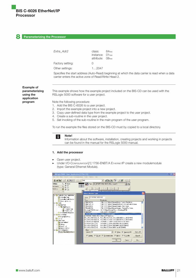
1. Add the processor
Open user project.Under I/O-CONFIGURATION\[1] 1756-ENBT/A ETHERNETIP create a new modulemodule(type: General Ethernet Module).
1.2.3.4.5.
�
�
Example of parameterizing using the application program
22
BIS C-6026 EtherNet/IPProcessor
Parameterizing the Processor8
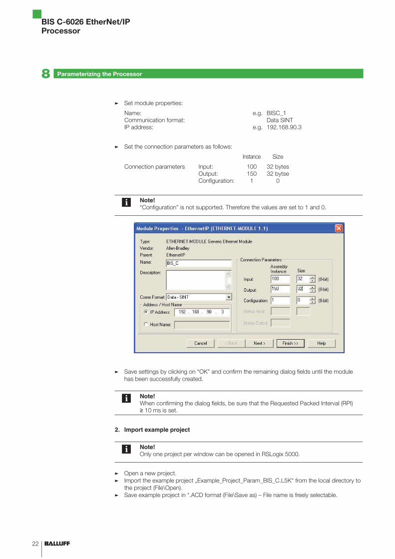
Set module properties:
Name:Communication format:IP address:
e.g.
e.g.
BISC_1Data SINT192.168.90.3
Set the connection parameters as follows:
Instance Size
Connection parameters Input:Output:Configuration:
1001501
32 bytes32 bytse
0
Note!“Configuration” is not supported. Therefore the values are set to 1 and 0.
Save settings by clicking on “OK” and confirm the remaining dialog fields until the module has been successfully created.
Note!When confirming the dialog fields, be sure that the Requested Packed Interval (RPI) ≥ 10 ms is set.
2. Import example project
Note!Only one project per window can be opened in RSLogix 5000.
Open a new project.Import the example project „Example_Project_Param_BIS_C.L5K“ from the local directory to the project (File\Open). Save example project in *.ACD format (File\Save as) – File name is freely selectable.
�
�
�
�
�
�
23www.balluff.com
BIS C-6026 EtherNet/IPProcessor
3. Copy user-defined data type
Under DATA TYPES\USER DEFINED in the example project copy „BISC_Userparameters“.Under DATA TYPES\USER DEFINED in the example project paste „BISC_Userparameters“.
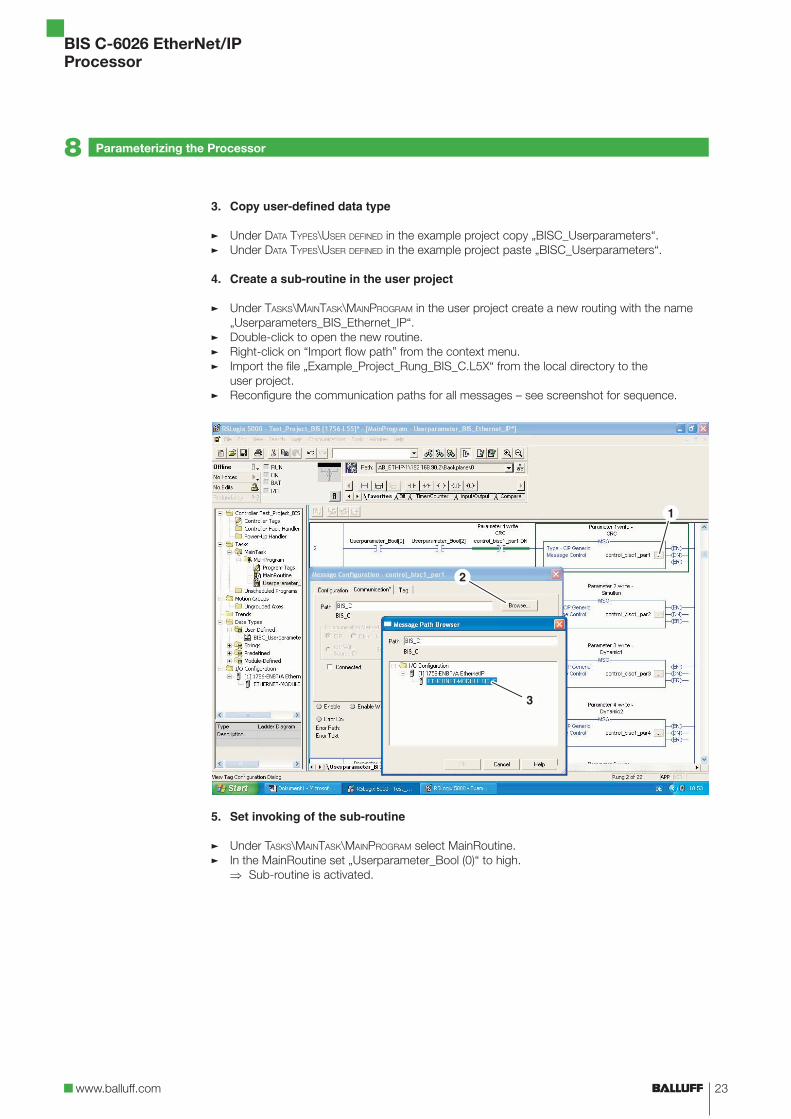
4. Create a sub-routine in the user project
Under TASKS\MAINTASK\MAINPROGRAM in the user project create a new routing with the name „Userparameters_BIS_Ethernet_IP“.
Double-click to open the new routine. Right-click on “Import flow path” from the context menu. Import the file „Example_Project_Rung_BIS_C.L5X“ from the local directory to theuser project.Reconfigure the communication paths for all messages – see screenshot for sequence.
5. Set invoking of the sub-routine
Under TASKS\MAINTASK\MAINPROGRAM select MainRoutine.In the MainRoutine set „Userparameter_Bool (0)“ to high.
Sub-routine is activated.
�
�
�
�
�
�
�
�
�
⇒
Parameterizing the Processor8
24
BIS C-6026 EtherNet/IPProcessor
Device Function9
9.1 Function principle BIS C-6026
Output buffer
Two buffers are required to exchange data and commands between the processor and the host system. Cyclical polling is used for exchanging the buffer contents. The buffer content depends on the cycle in which it is written (e.g. control commands at the start of the job). When writing the buffer, the transmitted data from the previous cycle are overwritten. Unwritten bytes are not deleted and retain their data content.
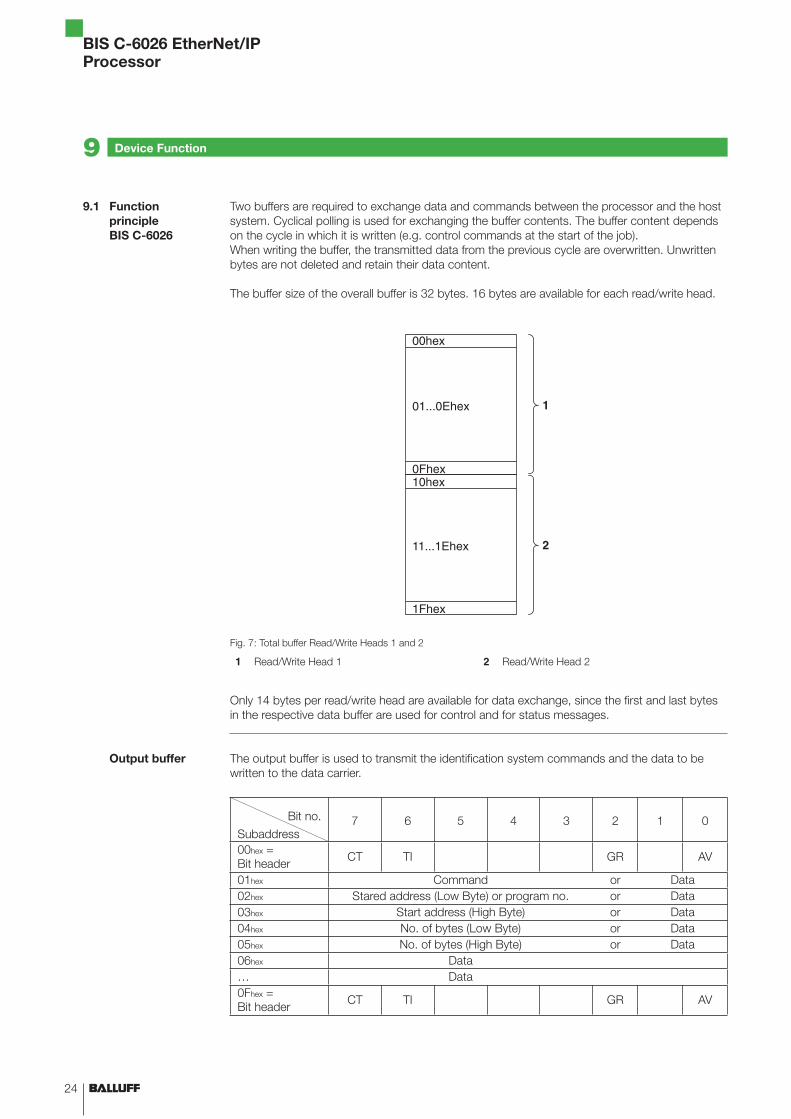
The buffer size of the overall buffer is 32 bytes. 16 bytes are available for each read/write head.
Fig. 7: Total buffer Read/Write Heads 1 and 2
1 Read/Write Head 1 2 Read/Write Head 2
Only 14 bytes per read/write head are available for data exchange, since the first and last bytes in the respective data buffer are used for control and for status messages.
The output buffer is used to transmit the identification system commands and the data to be written to the data carrier.
Bit no.
Subaddress7 6 5 4 3 2 1 0
00hex =Bit header CT TI GR AV
01hex Command or Data02hex Stared address (Low Byte) or program no. or Data03hex Start address (High Byte) or Data04hex No. of bytes (Low Byte) or Data05hex No. of bytes (High Byte) or Data06hex Data… Data0Fhex =Bit header CT TI GR AV
25www.balluff.com
BIS C-6026 EtherNet/IPProcessor
Device Function9
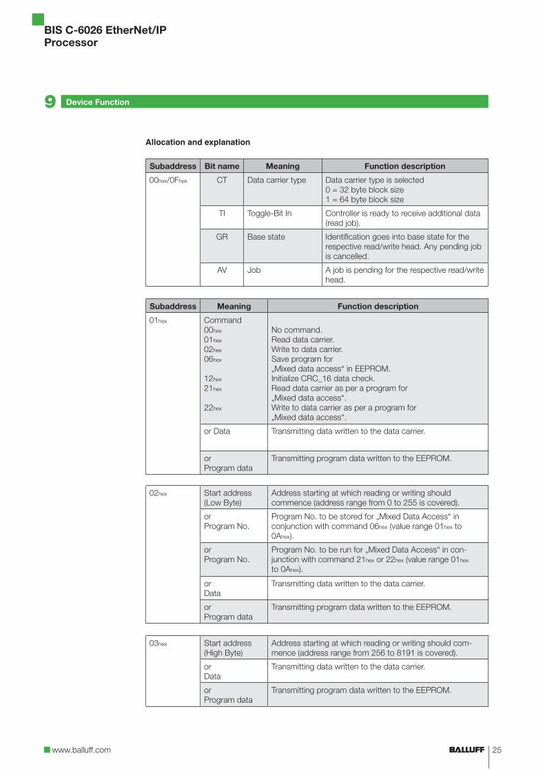
Allocation and explanation
Subaddress Bit name Meaning Function description
00hex/0Fhex CT Data carrier type Data carrier type is selected0 = 32 byte block size1 = 64 byte block size
TI Toggle-Bit In Controller is ready to receive additional data (read job).
GR Base state Identification goes into base state for the respective read/write head. Any pending job is cancelled.
AV Job A job is pending for the respective read/write head.
Subaddress Meaning Function description
01hex Command00hex
01hex
02hex
06hex
12hex
21hex
22hex
No command.Read data carrier.Write to data carrier.Save program for „Mixed data access“ in EEPROM.Initialize CRC_16 data check.Read data carrier as per a program for „Mixed data access“.Write to data carrier as per a program for „Mixed data access“.
or Data Transmitting data written to the data carrier.
or Program data
Transmitting program data written to the EEPROM.
02hex Start address(Low Byte)
Address starting at which reading or writing shouldcommence (address range from 0 to 255 is covered).
orProgram No.
Program No. to be stored for „Mixed Data Access“ in conjunction with command 06hex (value range 01hex to 0Ahex).
orProgram No.
Program No. to be run for „Mixed Data Access“ in con-junction with command 21hex or 22hex (value range 01hex to 0Ahex).
orData
Transmitting data written to the data carrier.
or Program data
Transmitting program data written to the EEPROM.
03hex Start address(High Byte)
Address starting at which reading or writing should com-mence (address range from 256 to 8191 is covered).
orData
Transmitting data written to the data carrier.
or Program data
Transmitting program data written to the EEPROM.
26
BIS C-6026 EtherNet/IPProcessor
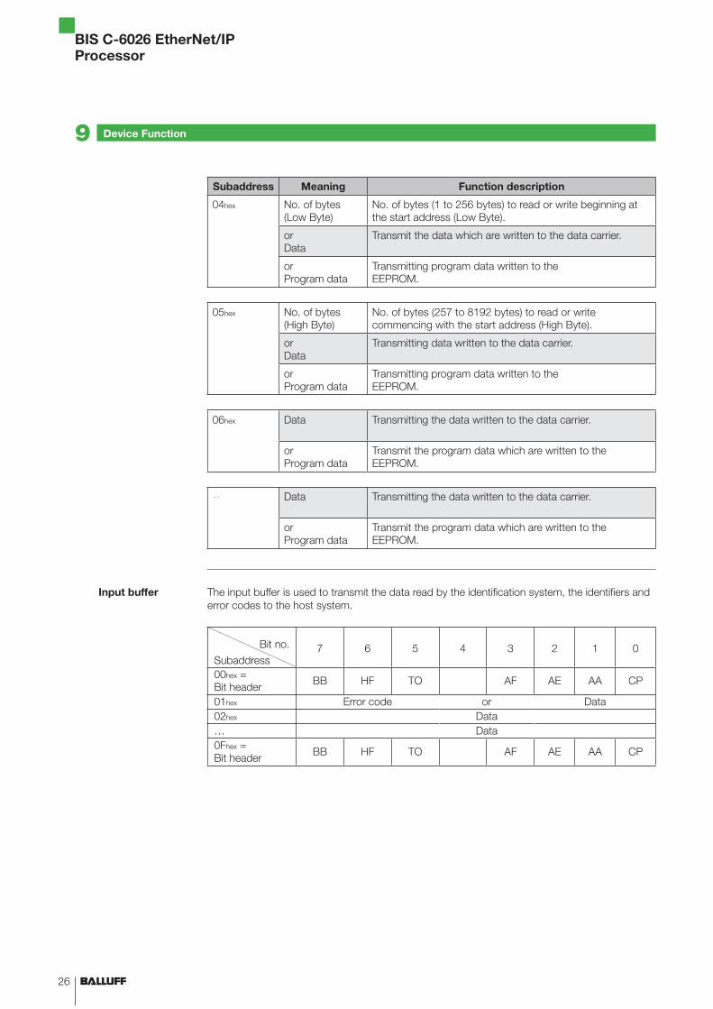
Subaddress Meaning Function description
04hex No. of bytes(Low Byte)
No. of bytes (1 to 256 bytes) to read or write beginning at the start address (Low Byte).
orData
Transmit the data which are written to the data carrier.
or Program data
Transmitting program data written to the EEPROM.
05hex No. of bytes (High Byte)
No. of bytes (257 to 8192 bytes) to read or write commencing with the start address (High Byte).
orData
Transmitting data written to the data carrier.
or Program data
Transmitting program data written to the EEPROM.
06hex Data Transmitting the data written to the data carrier.
or Program data
Transmit the program data which are written to the EEPROM.
… Data Transmitting the data written to the data carrier.
or Program data
Transmit the program data which are written to the EEPROM.
The input buffer is used to transmit the data read by the identification system, the identifiers and error codes to the host system.
Bit no.
Subaddress7 6 5 4 3 2 1 0
00hex = Bit header BB HF TO AF AE AA CP
01hex Error code or Data02hex Data… Data0Fhex = Bit header BB HF TO AF AE AA CP
Device Function9
Input buffer

27www.balluff.com
BIS C-6026 EtherNet/IPProcessor
Allocation and explanation
Subaddress Bit name Meaning Function description
00hex/0Fhex BB Ready Identification system is ready.
HF Head error Cable break on read/write head or no read/write head connected.
TO Toggle-Bit Out Read procedure: Identification system has additional data ready. Write procedure: Identification system can accept additional data.
AF Job error Error in processing the job, or job cancelled.
AE Job end Confirmation – Job ended without error.
AA Auftrag start Confirmation – Job was recognized and started.
CP Codetag Present There is a data carrier in the active zone of the read/write head.
Subaddress Meaning Function description
01hex Error code01hex
02hex
03hex
04hex
05hex
06hex
07hex
09hex
0Chex
0Dhex
0Ehex
0Fhex
Error number valid only with AF-bit!Job cannot be carried out becoffe there is no data carrier in the active zone of the read/write head.Read error.Data carrier was removed from the active zone of the read/write head during reading.Write error.Data carrier was removed from the active zone of the read/write head during writing.Memory access error.Invalid or no command for set AV-bit or number of bytes is 00hex.
Cable break on read/write head or no read/write head connected.EEPROM cannot be read or programmed.Communication fault with data carrier. CRC for read data and CRC for data carrier do not agree.1st and 2nd bit header are not identical. The 2nd bit header must be operated.
or Data Transmit data which were read from the data carrier.
02hex Data Transmit data which were read from the data carrier.
… Data Transmit data which were read from the data carrier.
Device Function9
28
BIS C-6026 EtherNet/IPProcessor
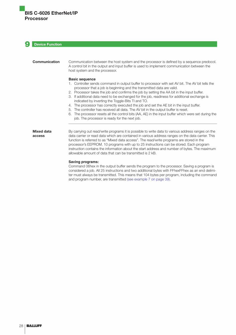
Communication between the host system and the processor is defined by a sequence predocol. A control bit in the output and input buffer is used to implement communication between the host system and the processor.
Basic sequenceController sends command in output buffer to processor with set AV bit. The AV bit tells the processor that a job is beginning and the transmitted data are valid. Processor takes the job and confirms the job by setting the AA bit in the input buffer. If additional data need to be exchanged for the job, readiness for additional exchange is indicated by inverting the Toggle-Bits TI and TO. The processor has correctly executed the job and set the AE bit in the input buffer. The controller has received all data. The AV bit in the output buffer is reset. The processor resets all the control bits (AA, AE) in the input buffer which were set during the job. The processor is ready for the next job.
By carrying out read/write programs it is possible to write data to various address ranges on the data carrier or read data which are contained in various address ranges on the data carrier. This function is referred to as “Mixed data access”. The read/write programs are stored in the processor’s EEPROM. 10 programs with up to 25 instructions can be stored. Each program instruction contains the information about the start address and number of bytes. The maximum allowable amount of data that can be transmitted is 2 kB.
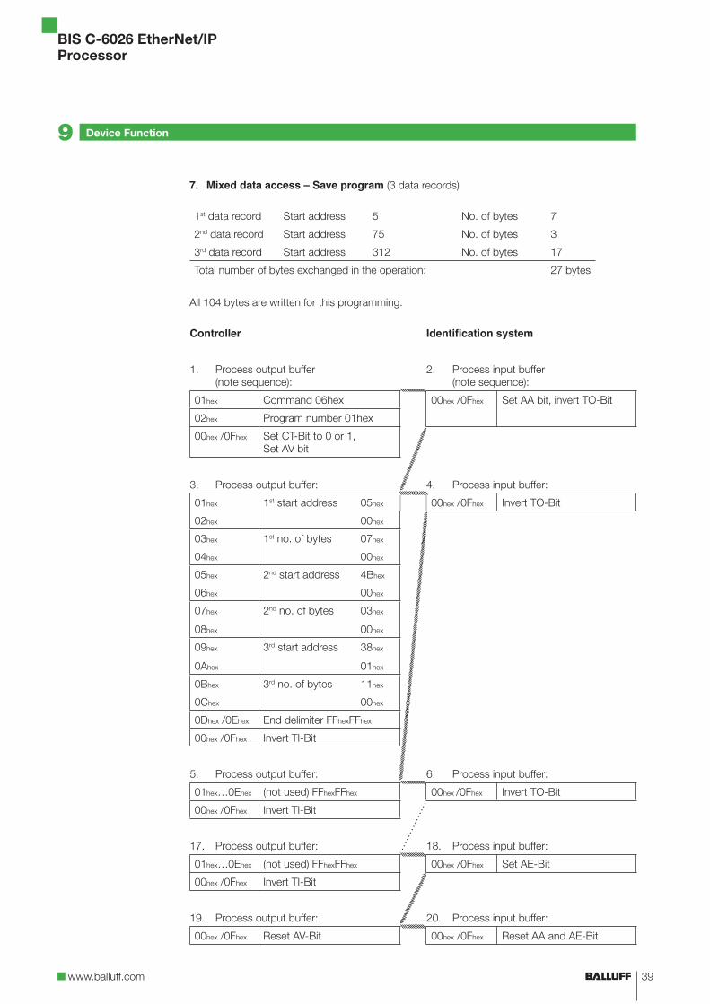
Saving programs: Command 06hex in the output buffer sends the program to the processor. Saving a program is considered a job. All 25 instructions and two additional bytes with FFhexFFhex as an end delimi-ter must always be transmitted. This means that 104 bytes per program, including the command and program number, are transmitted (see example 7 on page 39).
1.
2.3.
4.5.6.
Device Function9
Communication
Mixed data access
29www.balluff.com
BIS C-6026 EtherNet/IPProcessor
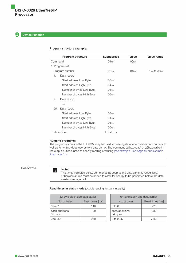
Program structure example:
Program structure Subaddress Value Value range
Command 01hex 06hex
1. Program set
Program number 02hex 01hex 01hex to 0Ahex
1. Data record
Start address Low Byte 03hex
Start address High Byte 04hex
Number of bytes Low Byte 05hex
Number of bytes High Byte 06hex
2. Data record
…
25. Data record
Start address Low Byte 03hex
Start address High Byte 04hex
Number of bytes Low Byte 05hex
Number of bytes High Byte 06hex
End delimiter FFhexFFhex
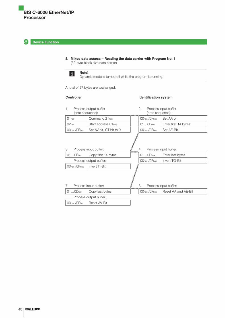
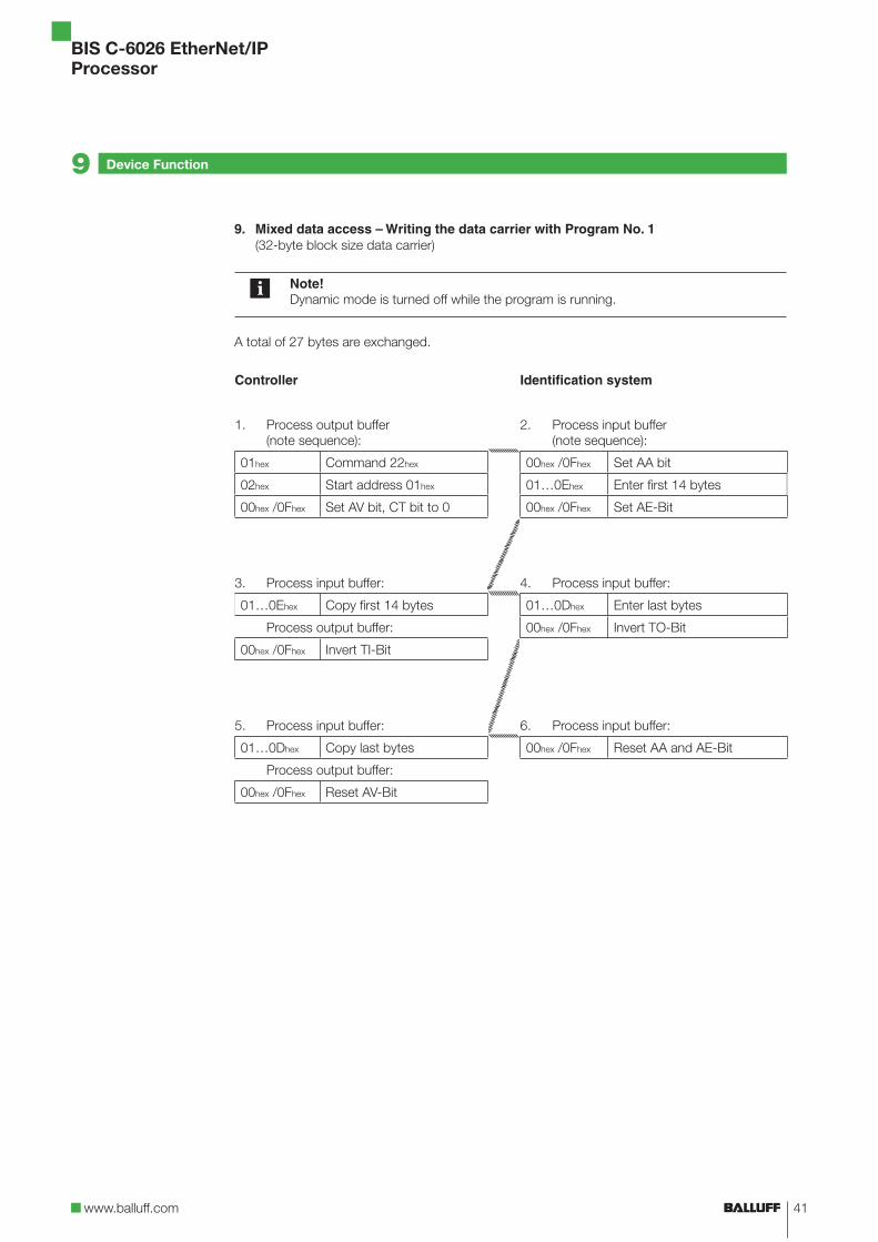
Running programs:The programs stores in the EEPROM may be used for reading data records from data carriers as well as for writing data records to a data carrier. The command 21hex (read) or 22hex (write) in the output buffer is used to specify reading or writing (see example 8 on page 40 and example 9 on page 41).
Note!The times indicated below commence as soon as the data carrier is recognized. Otherwise 45 ms must be added to allow for energy to be generated before the data carrier is recognized.
Read times in static mode (double reading for data integrity)
32-byte block size data carrier 64-byte block size data carrier
No. of bytes Read times [ms] No. of bytes Read times [ms]
0 to 31 110 0 to 63 220
each additional 32 bytes
120 each additional 64 bytes
230
0 to 255 950 0 to 2047 7350
Read/write
Device Function9
30
BIS C-6026 EtherNet/IPProcessor
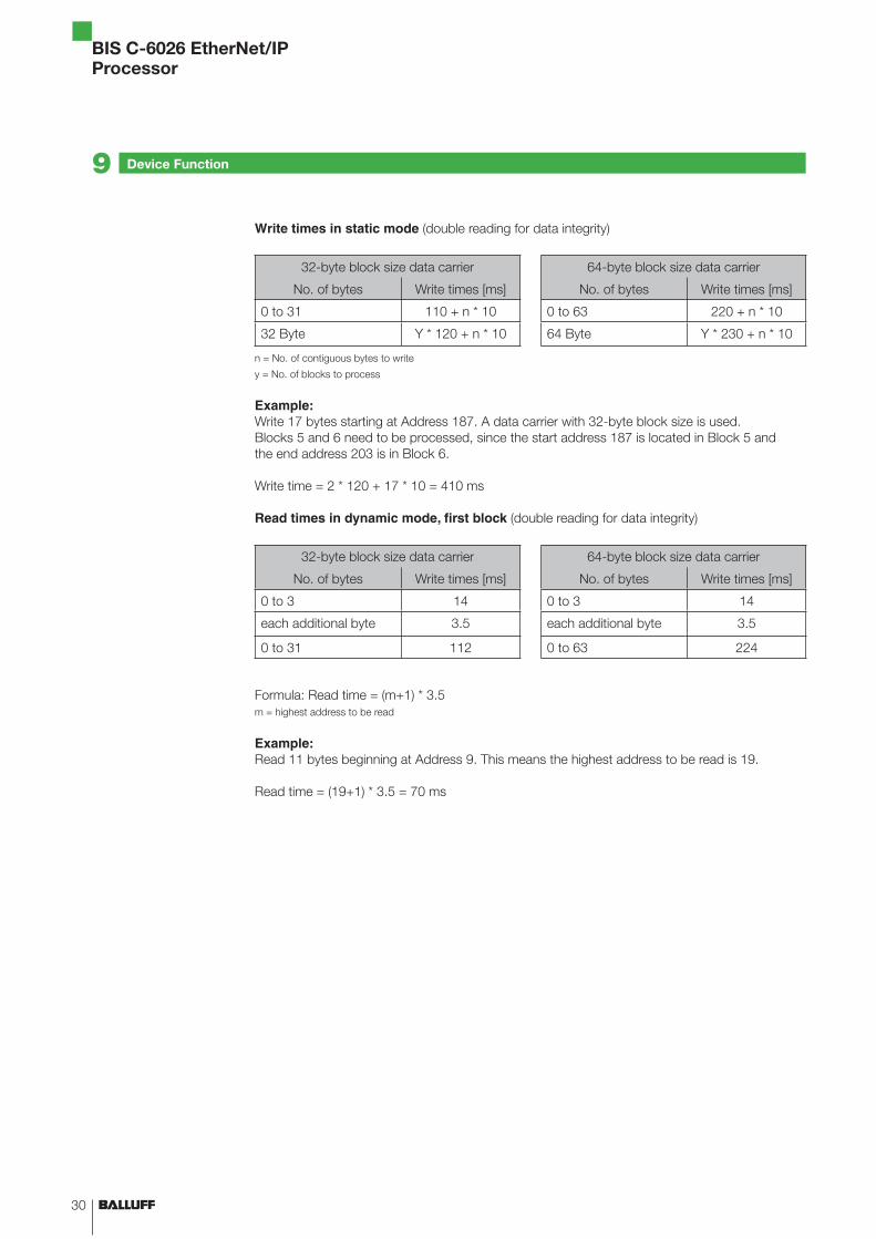
Write times in static mode (double reading for data integrity)
32-byte block size data carrier 64-byte block size data carrier
No. of bytes Write times [ms] No. of bytes Write times [ms]
0 to 31 110 + n * 10 0 to 63 220 + n * 10
32 Byte Y * 120 + n * 10 64 Byte Y * 230 + n * 10
n = No. of contiguous bytes to write
y = No. of blocks to process
Example:Write 17 bytes starting at Address 187. A data carrier with 32-byte block size is used. Blocks 5 and 6 need to be processed, since the start address 187 is located in Block 5 and the end address 203 is in Block 6.
Write time = 2 * 120 + 17 * 10 = 410 ms
Read times in dynamic mode, first block (double reading for data integrity)
32-byte block size data carrier 64-byte block size data carrier
No. of bytes Write times [ms] No. of bytes Write times [ms]
0 to 3 14 0 to 3 14
each additional byte 3.5 each additional byte 3.5
0 to 31 112 0 to 63 224
Formula: Read time = (m+1) * 3.5m = highest address to be read
Example:Read 11 bytes beginning at Address 9. This means the highest address to be read is 19.
Read time = (19+1) * 3.5 = 70 ms
Device Function9
31www.balluff.com
BIS C-6026 EtherNet/IPProcessor
9.2 Function indicators
Overview of indicators
Power-up
Diagnostics
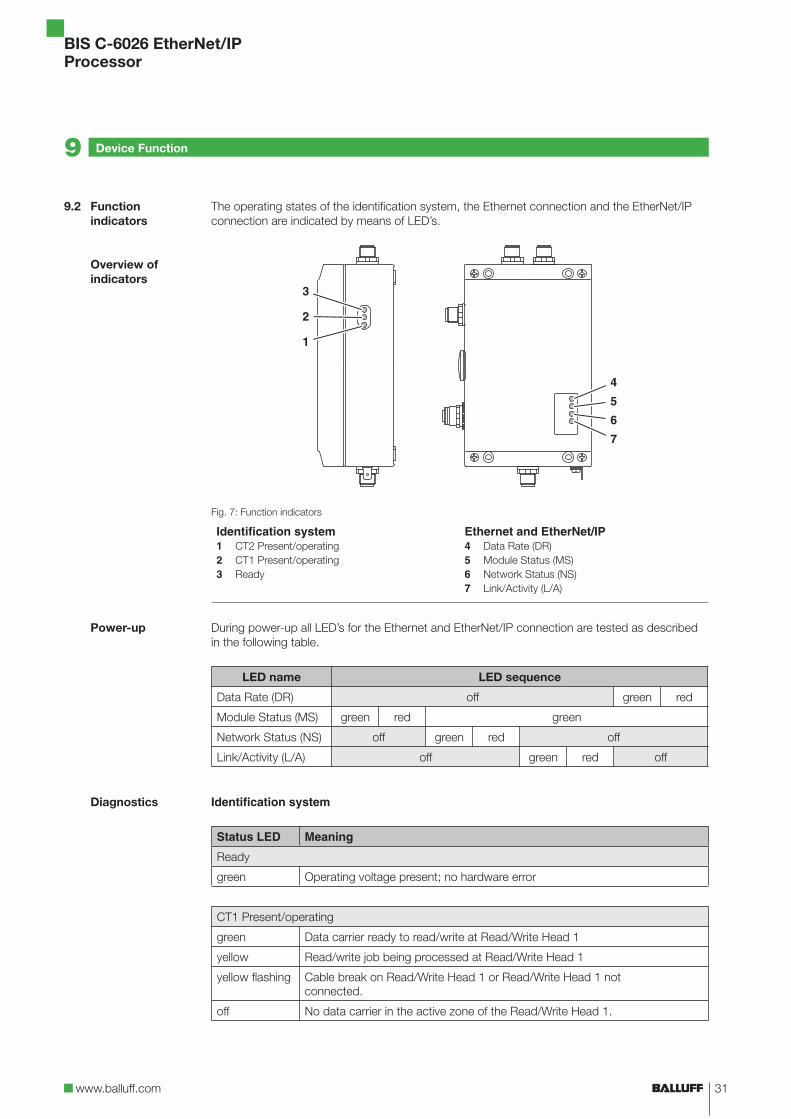
The operating states of the identification system, the Ethernet connection and the EtherNet/IP connection are indicated by means of LED’s.
Fig. 7: Function indicators
Identification system1 CT2 Present/operating2 CT1 Present/operating3 Ready
Ethernet and EtherNet/IP4 Data Rate (DR)5 Module Status (MS)6 Network Status (NS)7 Link/Activity (L/A)
During power-up all LED’s for the Ethernet and EtherNet/IP connection are tested as described in the following table.
LED name LED sequence
Data Rate (DR) off green red
Module Status (MS) green red green
Network Status (NS) off green red off
Link/Activity (L/A) off green red off
Identification system
Status LED Meaning
Ready
green Operating voltage present; no hardware error
CT1 Present/operating
green Data carrier ready to read/write at Read/Write Head 1
yellow Read/write job being processed at Read/Write Head 1
yellow flashing Cable break on Read/Write Head 1 or Read/Write Head 1 not connected.
off No data carrier in the active zone of the Read/Write Head 1.
Device Function9
32
BIS C-6026 EtherNet/IPProcessor
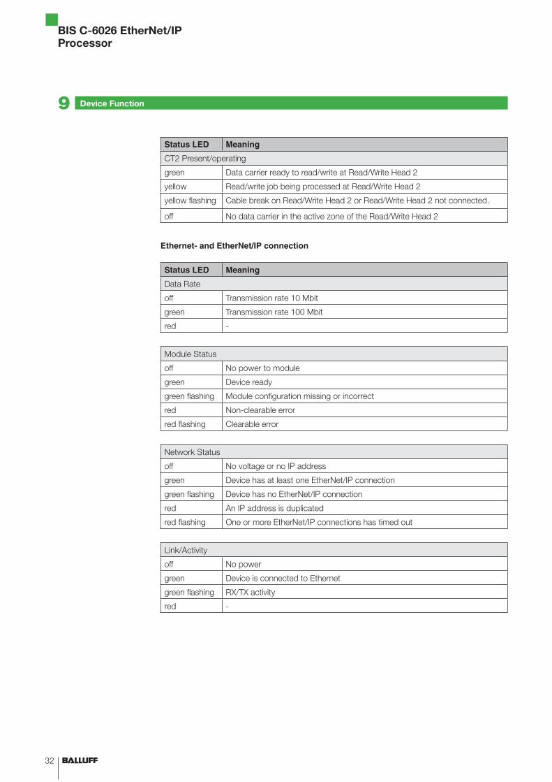
Status LED Meaning
CT2 Present/operating
green Data carrier ready to read/write at Read/Write Head 2
yellow Read/write job being processed at Read/Write Head 2
yellow flashing Cable break on Read/Write Head 2 or Read/Write Head 2 not connected.
off No data carrier in the active zone of the Read/Write Head 2
Ethernet- and EtherNet/IP connection
Status LED Meaning
Data Rate
off Transmission rate 10 Mbit
green Transmission rate 100 Mbit
red -
Module Status
off No power to module
green Device ready
green flashing Module configuration missing or incorrect
red Non-clearable error
red flashing Clearable error
Network Status
off No voltage or no IP address
green Device has at least one EtherNet/IP connection
green flashing Device has no EtherNet/IP connection
red An IP address is duplicated
red flashing One or more EtherNet/IP connections has timed out
Link/Activity
off No power
green Device is connected to Ethernet
green flashing RX/TX activity
red -
Device Function9
33www.balluff.com
BIS C-6026 EtherNet/IPProcessor
Device Function9
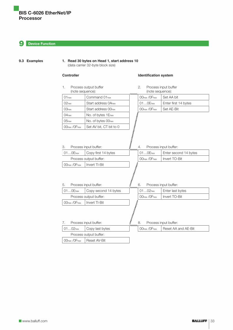
1. Read 30 bytes on Head 1, start address 10 (data carrier 32-byte block size)
Controller Identification system
1. Process output buffer (note sequence):
2. Process input buffer (note sequence):
01hex Command 01hex 00hex /0Fhex Set AA bit
02hex Start address 0Ahex 01…0Ehex Enter first 14 bytes
03hex Start address 00hex 00hex /0Fhex Set AE-Bit
04hex No. of bytes 1Ehex
05hex No. of bytes 00hex
00hex /0Fhex Set AV bit, CT bit to 0
3. Process input buffer: 4. Process input buffer:
01…0Ehex Copy first 14 bytes 01…0Ehex Enter second 14 bytes
Process output buffer: 00hex /0Fhex Invert TO-Bit
00hex /0Fhex Invert TI-Bit
5. Process input buffer: 6. Process input buffer:
01…0Ehex Copy second 14 bytes 01…02hex Enter last bytes
Process output buffer: 00hex /0Fhex Invert TO-Bit
00hex /0Fhex Invert TI-Bit
7. Process input buffer: 8. Process input buffer:
01…02hex Copy last bytes 00hex /0Fhex Reset AA and AE-Bit
Process output buffer:
00hex /0Fhex Reset AV-Bit
9.3 Examples
34
BIS C-6026 EtherNet/IPProcessor
Device Function9
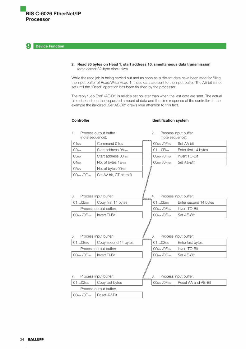
2. Read 30 bytes on Head 1, start address 10, simultaneous data transmission (data carrier 32-byte block size)
While the read job is being carried out and as soon as sufficient data have been read for filling the input buffer of Read/Write Head 1, these data are sent to the input buffer. The AE bit is not set until the “Read” operation has been finished by the processor.
The reply “Job End” (AE-Bit) is reliably set no later than when the last data are sent. The actual time depends on the requested amount of data and the time response of the controller. In the example the italicized „Set AE-Bit“ draws your attention to this fact.
Controller Identification system
1. Process output buffer (note sequence):
2. Process input buffer (note sequence):
01hex Command 01hex 00hex /0Fhex Set AA bit
02hex Start address 0Ahex 01…0Ehex Enter first 14 bytes
03hex Start address 00hex 00hex /0Fhex Invert TO-Bit
04hex No. of bytes 1Ehex 00hex /0Fhex Set AE-Bit
05hex No. of bytes 00hex
00hex /0Fhex Set AV bit, CT bit to 0
3. Process input buffer: 4. Process input buffer:
01…0Ehex Copy first 14 bytes 01…0Ehex Enter second 14 bytes
Process output buffer: 00hex /0Fhex Invert TO-Bit
00hex /0Fhex Invert TI-Bit 00hex /0Fhex Set AE-Bit
5. Process input buffer: 6. Process input buffer:
01…0Ehex Copy second 14 bytes 01…02hex Enter last bytes
Process output buffer: 00hex /0Fhex Invert TO-Bit
00hex /0Fhex Invert TI-Bit 00hex /0Fhex Set AE-Bit
7. Process input buffer: 8. Process input buffer:
01…02hex Copy last bytes 00hex /0Fhex Reset AA and AE-Bit
Process output buffer:
00hex /0Fhex Reset AV-Bit
35www.balluff.com
BIS C-6026 EtherNet/IPProcessor
Device Function9
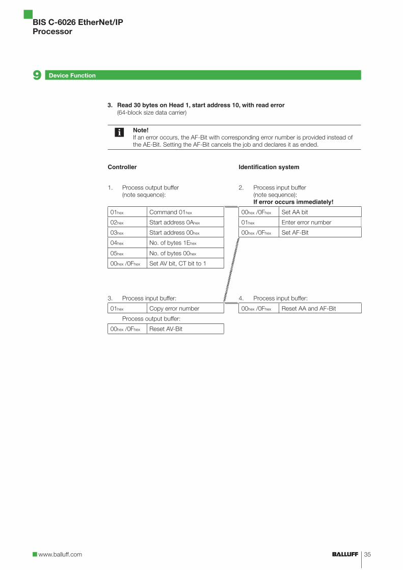
3. Read 30 bytes on Head 1, start address 10, with read error (64-block size data carrier)
Note!If an error occurs, the AF-Bit with corresponding error number is provided instead of the AE-Bit. Setting the AF-Bit cancels the job and declares it as ended.
Controller Identification system
1. Process output buffer (note sequence):
2. Process input buffer (note sequence): If error occurs immediately!
01hex Command 01hex 00hex /0Fhex Set AA bit
02hex Start address 0Ahex 01hex Enter error number
03hex Start address 00hex 00hex /0Fhex Set AF-Bit
04hex No. of bytes 1Ehex
05hex No. of bytes 00hex
00hex /0Fhex Set AV bit, CT bit to 1
3. Process input buffer: 4. Process input buffer:
01hex Copy error number 00hex /0Fhex Reset AA and AF-Bit
Process output buffer:
00hex /0Fhex Reset AV-Bit
36
BIS C-6026 EtherNet/IPProcessor
Device Function9
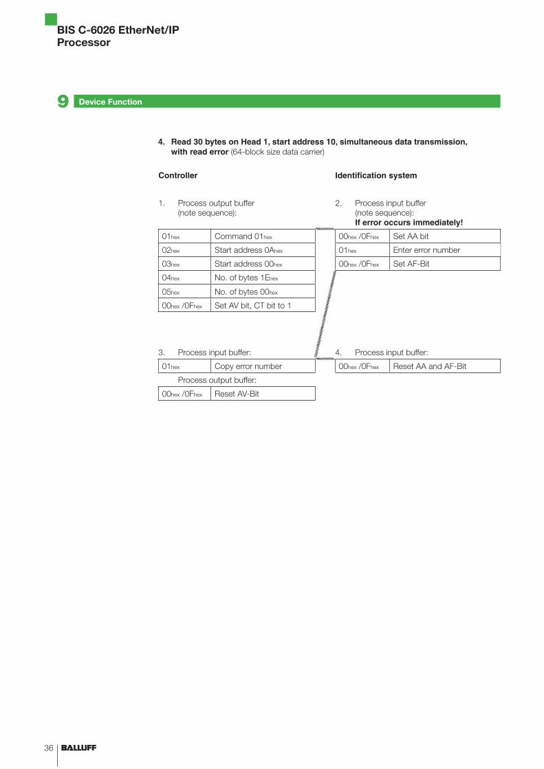
4. Read 30 bytes on Head 1, start address 10, simultaneous data transmission, with read error (64-block size data carrier)
Controller Identification system
1. Process output buffer (note sequence):
2. Process input buffer (note sequence): If error occurs immediately!
01hex Command 01hex 00hex /0Fhex Set AA bit
02hex Start address 0Ahex 01hex Enter error number
03hex Start address 00hex 00hex /0Fhex Set AF-Bit
04hex No. of bytes 1Ehex
05hex No. of bytes 00hex
00hex /0Fhex Set AV bit, CT bit to 1
3. Process input buffer: 4. Process input buffer:
01hex Copy error number 00hex /0Fhex Reset AA and AF-Bit
Process output buffer:
00hex /0Fhex Reset AV-Bit
37www.balluff.com
BIS C-6026 EtherNet/IPProcessor
Device Function9
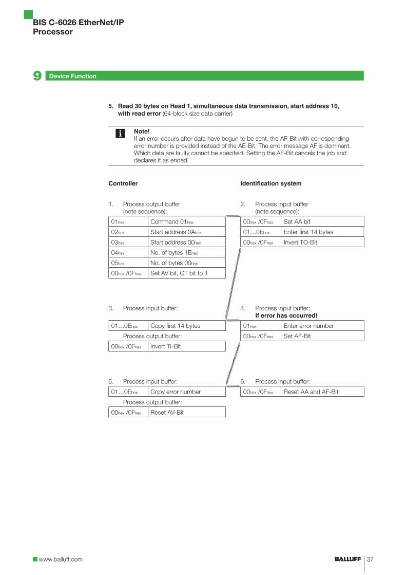
5. Read 30 bytes on Head 1, simultaneous data transmission, start address 10, with read error (64-block size data carrier)
Note!If an error occurs after data have begun to be sent, the AF-Bit with corresponding error number is provided instead of the AE-Bit. The error message AF is dominant. Which data are faulty cannot be specified. Setting the AF-Bit cancels the job and declares it as ended.
Controller Identification system
1. Process output buffer (note sequence):
2. Process input buffer (note sequence):
01hex Command 01hex 00hex /0Fhex Set AA bit
02hex Start address 0Ahex 01…0Ehex Enter first 14 bytes
03hex Start address 00hex 00hex /0Fhex Invert TO-Bit
04hex No. of bytes 1Ehex
05hex No. of bytes 00hex
00hex /0Fhex Set AV bit, CT bit to 1
3. Process input buffer: 4. Process input buffer:If error has occurred!
01…0Ehex Copy first 14 bytes 01hex Enter error number
Process output buffer: 00hex /0Fhex Set AF-Bit
00hex /0Fhex Invert TI-Bit
5. Process input buffer: 6. Process input buffer:
01…0Ehex Copy error number 00hex /0Fhex Reset AA and AF-Bit
Process output buffer:
00hex /0Fhex Reset AV-Bit
38
BIS C-6026 EtherNet/IPProcessor
Device Function9
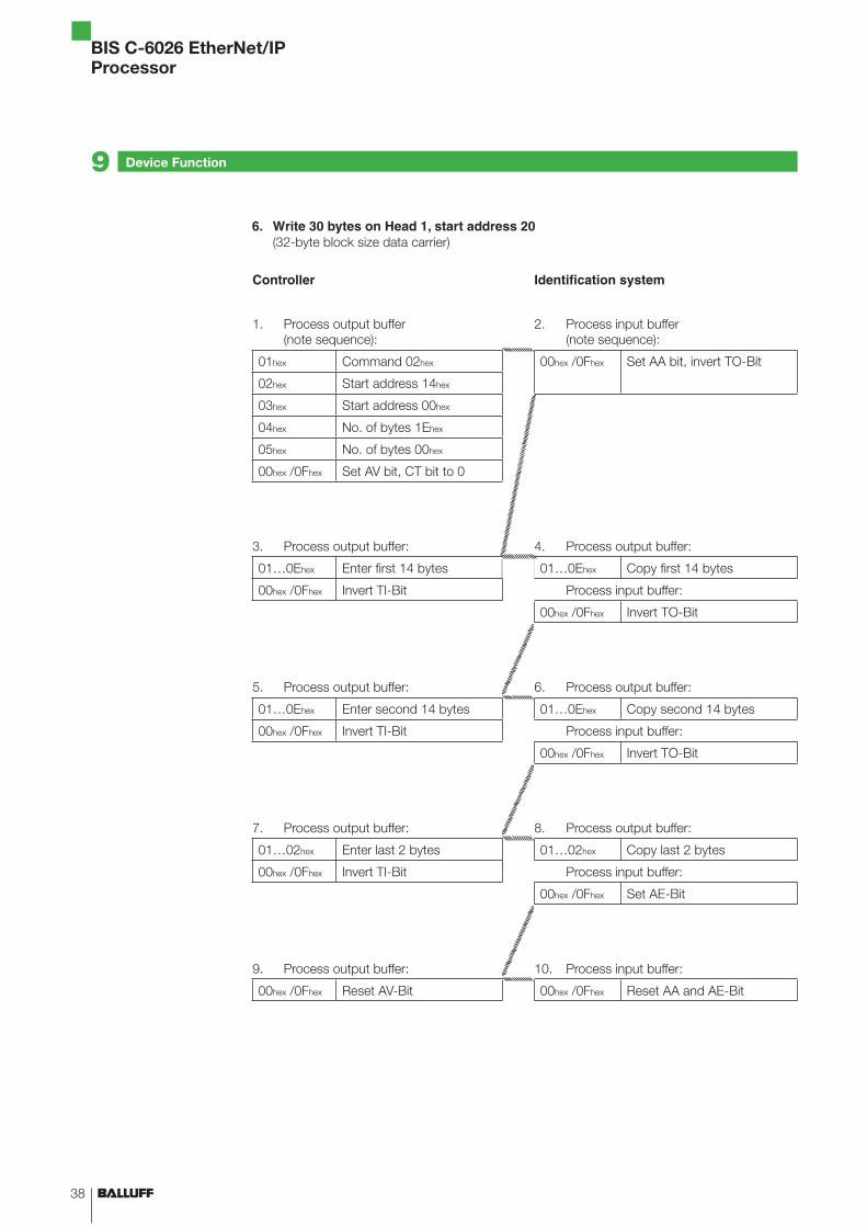
6. Write 30 bytes on Head 1, start address 20 (32-byte block size data carrier)
Controller Identification system
1. Process output buffer (note sequence):
2. Process input buffer (note sequence):
01hex Command 02hex 00hex /0Fhex Set AA bit, invert TO-Bit
02hex Start address 14hex
03hex Start address 00hex
04hex No. of bytes 1Ehex
05hex No. of bytes 00hex
00hex /0Fhex Set AV bit, CT bit to 0
3. Process output buffer: 4. Process output buffer:
01…0Ehex Enter first 14 bytes 01…0Ehex Copy first 14 bytes
00hex /0Fhex Invert TI-Bit Process input buffer:
00hex /0Fhex Invert TO-Bit
5. Process output buffer: 6. Process output buffer:
01…0Ehex Enter second 14 bytes 01…0Ehex Copy second 14 bytes
00hex /0Fhex Invert TI-Bit Process input buffer:
00hex /0Fhex Invert TO-Bit
7. Process output buffer: 8. Process output buffer:
01…02hex Enter last 2 bytes 01…02hex Copy last 2 bytes
00hex /0Fhex Invert TI-Bit Process input buffer:
00hex /0Fhex Set AE-Bit
9. Process output buffer: 10. Process input buffer:
00hex /0Fhex Reset AV-Bit 00hex /0Fhex Reset AA and AE-Bit
39www.balluff.com
BIS C-6026 EtherNet/IPProcessor
Device Function9
7. Mixed data access – Save program (3 data records)
1st data record Start address 5 No. of bytes 7
2nd data record Start address 75 No. of bytes 3
3rd data record Start address 312 No. of bytes 17
Total number of bytes exchanged in the operation: 27 bytes
All 104 bytes are written for this programming.
Controller Identification system
1. Process output buffer (note sequence):
2. Process input buffer (note sequence):
01hex Command 06hex 00hex /0Fhex Set AA bit, invert TO-Bit
02hex Program number 01hex
00hex /0Fhex Set CT-Bit to 0 or 1,Set AV bit
3. Process output buffer: 4. Process input buffer:
01hex 1st start address 05hex 00hex /0Fhex Invert TO-Bit
02hex 00hex
03hex 1st no. of bytes 07hex
04hex 00hex
05hex 2nd start address 4Bhex
06hex 00hex
07hex 2nd no. of bytes 03hex
08hex 00hex
09hex 3rd start address 38hex
0Ahex 01hex
0Bhex 3rd no. of bytes 11hex
0Chex 00hex
0Dhex /0Ehex End delimiter FFhexFFhex
00hex /0Fhex Invert TI-Bit
5. Process output buffer: 6. Process input buffer:
01hex…0Ehex (not used) FFhexFFhex 00hex /0Fhex Invert TO-Bit
00hex /0Fhex Invert TI-Bit
17. Process output buffer: 18. Process input buffer:
01hex…0Ehex (not used) FFhexFFhex 00hex /0Fhex Set AE-Bit
00hex /0Fhex Invert TI-Bit
19. Process output buffer: 20. Process input buffer:
00hex /0Fhex Reset AV-Bit 00hex /0Fhex Reset AA and AE-Bit
40
BIS C-6026 EtherNet/IPProcessor
Device Function9
8. Mixed data access – Reading the data carrier with Program No. 1 (32-byte block size data carrier)
Note!Dynamic mode is turned off while the program is running.
A total of 27 bytes are exchanged.
Controller Identification system
1. Process output buffer (note sequence):
2. Process input buffer (note sequence):
01hex Command 21hex 00hex /0Fhex Set AA bit
02hex Start address 01hex 01…0Ehex Enter first 14 bytes
00hex /0Fhex Set AV bit, CT bit to 0 00hex /0Fhex Set AE-Bit
3. Process input buffer: 4. Process input buffer:
01…0Ehex Copy first 14 bytes 01…0Dhex Enter last bytes
Process output buffer: 00hex /0Fhex Invert TO-Bit
00hex /0Fhex Invert TI-Bit
7. Process input buffer: 8. Process input buffer:
01…0Dhex Copy last bytes 00hex /0Fhex Reset AA and AE-Bit
Process output buffer:
00hex /0Fhex Reset AV-Bit
41www.balluff.com
BIS C-6026 EtherNet/IPProcessor
9. Mixed data access – Writing the data carrier with Program No. 1 (32-byte block size data carrier)
Note!Dynamic mode is turned off while the program is running.
A total of 27 bytes are exchanged.
Controller Identification system
1. Process output buffer (note sequence):
2. Process input buffer (note sequence):
01hex Command 22hex 00hex /0Fhex Set AA bit
02hex Start address 01hex 01…0Ehex Enter first 14 bytes
00hex /0Fhex Set AV bit, CT bit to 0 00hex /0Fhex Set AE-Bit
3. Process input buffer: 4. Process input buffer:
01…0Ehex Copy first 14 bytes 01…0Dhex Enter last bytes
Process output buffer: 00hex /0Fhex Invert TO-Bit
00hex /0Fhex Invert TI-Bit
5. Process input buffer: 6. Process input buffer:
01…0Dhex Copy last bytes 00hex /0Fhex Reset AA and AE-Bit
Process output buffer:
00hex /0Fhex Reset AV-Bit
Device Function9
42
BIS C-6026 EtherNet/IPProcessor
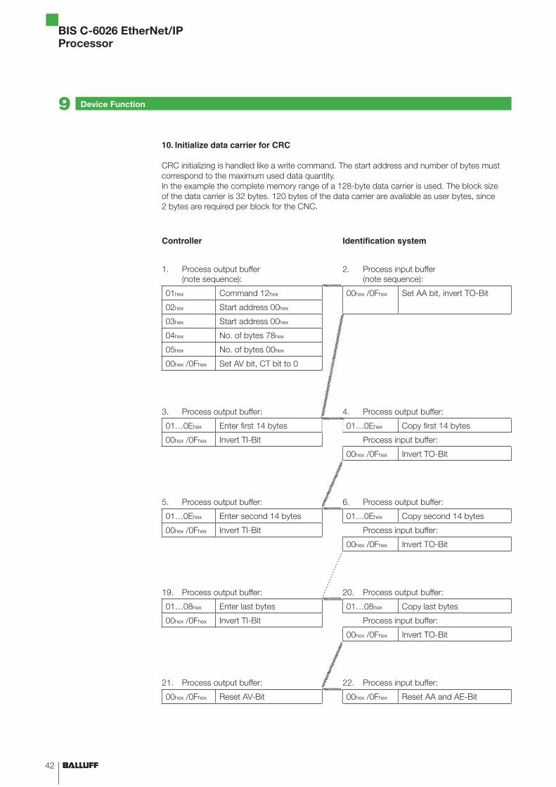
10. Initialize data carrier for CRC
CRC initializing is handled like a write command. The start address and number of bytes must correspond to the maximum used data quantity.In the example the complete memory range of a 128-byte data carrier is used. The block size of the data carrier is 32 bytes. 120 bytes of the data carrier are available as user bytes, since 2 bytes are required per block for the CNC.
Controller Identification system
1. Process output buffer (note sequence):
2. Process input buffer (note sequence):
01hex Command 12hex 00hex /0Fhex Set AA bit, invert TO-Bit
02hex Start address 00hex
03hex Start address 00hex
04hex No. of bytes 78hex
05hex No. of bytes 00hex
00hex /0Fhex Set AV bit, CT bit to 0
3. Process output buffer: 4. Process output buffer:
01…0Ehex Enter first 14 bytes 01…0Ehex Copy first 14 bytes
00hex /0Fhex Invert TI-Bit Process input buffer:
00hex /0Fhex Invert TO-Bit
5. Process output buffer: 6. Process output buffer:
01…0Ehex Enter second 14 bytes 01…0Ehex Copy second 14 bytes
00hex /0Fhex Invert TI-Bit Process input buffer:
00hex /0Fhex Invert TO-Bit
19. Process output buffer: 20. Process output buffer:
01…08hex Enter last bytes 01…08hex Copy last bytes
00hex /0Fhex Invert TI-Bit Process input buffer:
00hex /0Fhex Invert TO-Bit
21. Process output buffer: 22. Process input buffer:
00hex /0Fhex Reset AV-Bit 00hex /0Fhex Reset AA and AE-Bit
Device Function9
43www.balluff.com
BIS C-6026 EtherNet/IPProcessor
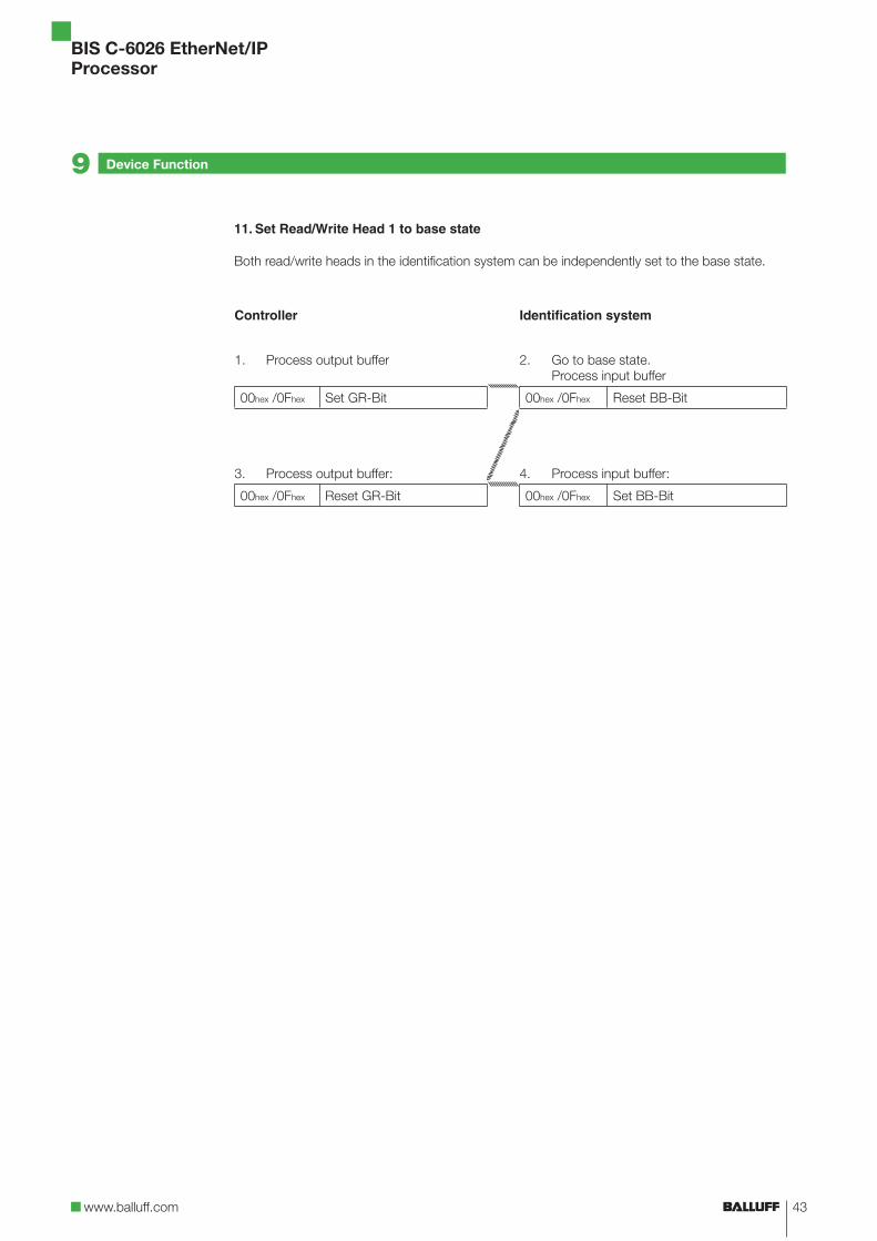
11. Set Read/Write Head 1 to base state
Both read/write heads in the identification system can be independently set to the base state.
Controller Identification system
1. Process output buffer 2. Go to base state.Process input buffer
00hex /0Fhex Set GR-Bit 00hex /0Fhex Reset BB-Bit
3. Process output buffer: 4. Process input buffer:
00hex /0Fhex Reset GR-Bit 00hex /0Fhex Set BB-Bit
Device Function9
44
BIS C-6026 EtherNet/IPProcessor
Appendix
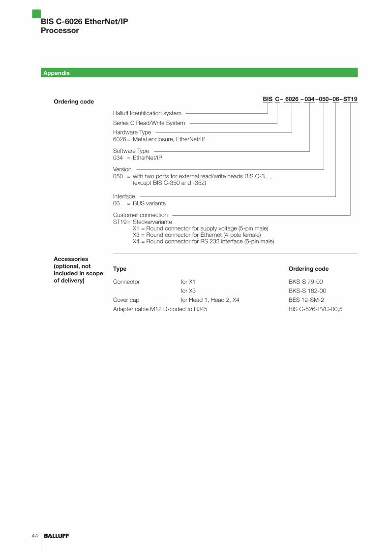
BIS C– 6026 – 034 –050–06–ST19
Balluff Identification system
Series C Read/Write System
Hardware Type6026= Metal enclosure, EtherNet/IP
Software Type034 = EtherNet/IP
Version050 = with two ports for external read/write heads BIS C-3_ _
(except BIS C-350 and -352)
Interface06 = BUS variants
Customer connectionST19= Steckervariante
X1 = Round connector for supply voltage (5-pin male)X3 = Round connector for Ethernet (4-pole female)X4 = Round connector for RS 232 interface (5-pin male)
Type Ordering code
Connector for X1 BKS-S 79-00
for X3 BKS-S 182-00
Cover cap for Head 1, Head 2, X4 BES 12-SM-2
Adapter cable M12 D-coded to RJ45 BIS C-526-PVC-00,5
Ordering code
Accessories(optional, notincluded in scope of delivery)
45www.balluff.com
BIS C-6026 EtherNet/IPProcessor
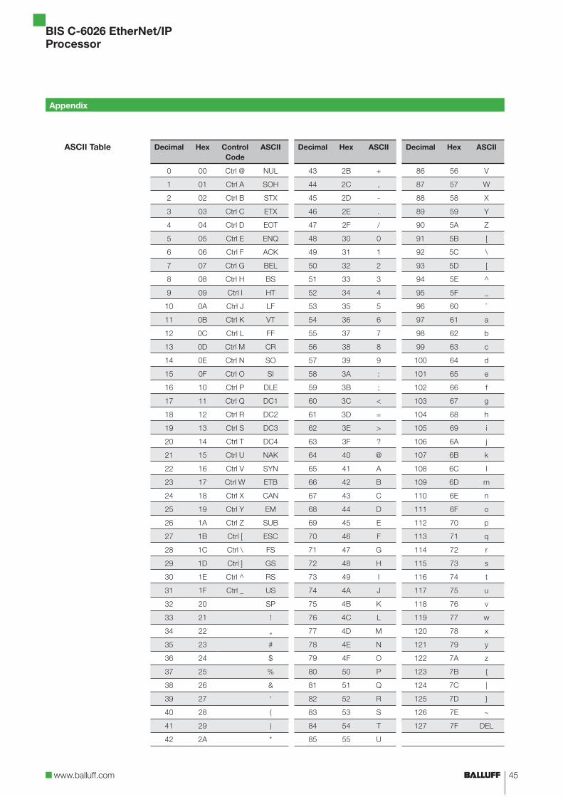
Decimal Hex Control Code
ASCII Decimal Hex ASCII Decimal Hex ASCII
0 00 Ctrl @ NUL 43 2B + 86 56 V
1 01 Ctrl A SOH 44 2C , 87 57 W
2 02 Ctrl B STX 45 2D - 88 58 X
3 03 Ctrl C ETX 46 2E . 89 59 Y
4 04 Ctrl D EOT 47 2F / 90 5A Z
5 05 Ctrl E ENQ 48 30 0 91 5B [
6 06 Ctrl F ACK 49 31 1 92 5C \
7 07 Ctrl G BEL 50 32 2 93 5D [
8 08 Ctrl H BS 51 33 3 94 5E ^
9 09 Ctrl I HT 52 34 4 95 5F _
10 0A Ctrl J LF 53 35 5 96 60 `
11 0B Ctrl K VT 54 36 6 97 61 a
12 0C Ctrl L FF 55 37 7 98 62 b
13 0D Ctrl M CR 56 38 8 99 63 c
14 0E Ctrl N SO 57 39 9 100 64 d
15 0F Ctrl O SI 58 3A : 101 65 e
16 10 Ctrl P DLE 59 3B ; 102 66 f
17 11 Ctrl Q DC1 60 3C < 103 67 g
18 12 Ctrl R DC2 61 3D = 104 68 h
19 13 Ctrl S DC3 62 3E > 105 69 i
20 14 Ctrl T DC4 63 3F ? 106 6A j
21 15 Ctrl U NAK 64 40 @ 107 6B k
22 16 Ctrl V SYN 65 41 A 108 6C l
23 17 Ctrl W ETB 66 42 B 109 6D m
24 18 Ctrl X CAN 67 43 C 110 6E n
25 19 Ctrl Y EM 68 44 D 111 6F o
26 1A Ctrl Z SUB 69 45 E 112 70 p
27 1B Ctrl [ ESC 70 46 F 113 71 q
28 1C Ctrl \ FS 71 47 G 114 72 r
29 1D Ctrl ] GS 72 48 H 115 73 s
30 1E Ctrl ^ RS 73 49 I 116 74 t
31 1F Ctrl _ US 74 4A J 117 75 u
32 20 SP 75 4B K 118 76 v
33 21 ! 76 4C L 119 77 w
34 22 „ 77 4D M 120 78 x
35 23 # 78 4E N 121 79 y
36 24 $ 79 4F O 122 7A z
37 25 % 80 50 P 123 7B {
38 26 & 81 51 Q 124 7C |
39 27 ‘ 82 52 R 125 7D }
40 28 ( 83 53 S 126 7E ~
41 29 ) 84 54 T 127 7F DEL
42 2A * 85 55 U
Appendix
ASCII Table
46
BIS C-6026 EtherNet/IPProcessor
ADimensions 12Wiring diagrams 14Display elements 31
Power-on 31EtherNet/IP connection 32Identifi cation system 31
ASCII-Table 45Output buffer 24
Command 25Bit header 24Mixed data access 25
ProcessorDisplay elements 31Output buffer 24Data integrity 10Input buffer 26Function principle 24Total buffer 24Communication 28Installation 14Parameterizing 19Product description 10Control function 10
Auto-Read 19
BIntended use 6Operating conditions 13Bus connection 11
CCRC check 18
Error message 18Initializing 18Checksum 18
DData integrity 10
CRC_16 data check 10Double read 10
DHCP 16Double bit header 10Dynamic mode 19
EEDS fi le 19Input buffer 26
Bit header 26Error code 27
Electrical data 12EtherNet/IP 11
FFunction indicators 13Function principle 10, 24
GMixed data access 28
Run programs 29Save programs 28
Total buffer 24
IIP address 16
AnyBus IPconfig 16DHCP 16
LRead times
Dynamic mode 30Static mode 29
MMechanical data 12Installation
Wiring diagrams 14Processor 14
PParameters
CRC_16 19Dynamic1 20Dynamic2 20Extra_Adr1 20Extra_Adr2 21Extra1 20Extra2 20Simultaneous 19
ParameterizingUser program 19EDS fi le 19
Product description 10
RRSLoogix 5000 19
SWrite times 30Safety 6
Operation 6Start-up 6Installation 6
Simultaneous data transmission 18Control bit
Job 25, 28
Job start 27, 28Job end 18, 27, 28Job error 27Codetag Present 19, 27Data carrier type 25Base state 25Head error 27Toggle-Bit In 18, 25, 28Toggle-Bit Out 18, 27, 28
Control function 10Double bit header 10
TTechnical data
Dimensions 12Operating conditions 13Electrical data 12Function indicators 13Mechanical data 12
Ordering code 44
ZAccessories 44
Index

Balluff GmbHSchurwaldstrasse 973765 Neuhausen a.d.F.GermanyPhone +49 (0) 71 58/1 73-0Fax +49 (0) 71 58/50 10E-Mail: [email protected]
No.
000
000
E . E
ditio
n 05
12;
Sub
ject
s to
mod
ifi ca
tion.
www.balluff.com
www.balluff.com


