20 October 2014 SULPHUR TECHNOLOGY MANAGER BLACK & VEATCH ENERGY BILL BRECKENRIDGE MIDDLE EAST SULPHUR PLANT OPERATIONS FORUM AGENDA Interactive Discussion Trends in Overall Plant Emissions Regional / Global Market Perspectives Technical Topics CBA Performance: Improvements & Feedback Organic Sulfur in Acid Gas Contaminated Acid Gas Design Basis
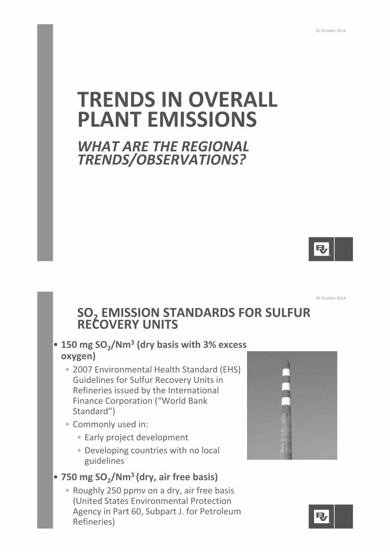
• 150 mg SO2/Nm3 (dry basis with 3% excessoxygen)• 2007 Environmental Health Standard (EHS)Guidelines for Sulfur Recovery Units inRefineries issued by the InternationalFinance Corporation (“World BankStandard”)
• Commonly used in:• Early project development• Developing countries with no localguidelines
• 750 mg SO2/Nm3 (dry, air free basis)• Roughly 250 ppmv on a dry, air free basis(United States Environmental ProtectionAgency in Part 60, Subpart J. for PetroleumRefineries)
SO2 EMISSION STANDARDS FOR SULFURRECOVERY UNITS
20 October 2014
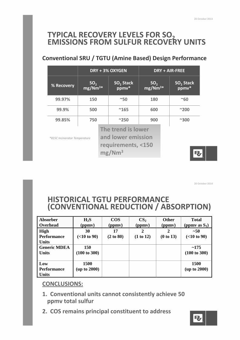
TYPICAL RECOVERY LEVELS FOR SO2EMISSIONS FROM SULFUR RECOVERY UNITS
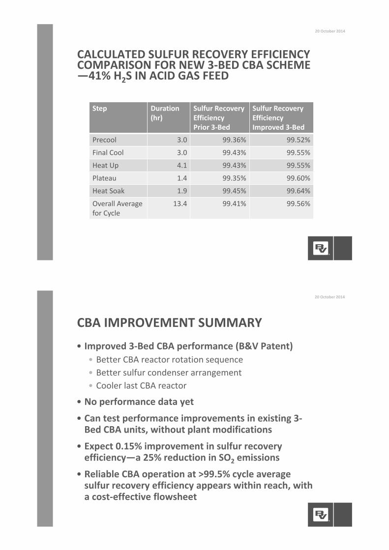
• No performance data yet• Can test performance improvements in existing 3Bed CBA units, without plant modifications
• Expect 0.15% improvement in sulfur recoveryefficiency—a 25% reduction in SO2 emissions
• Reliable CBA operation at >99.5% cycle averagesulfur recovery efficiency appears within reach, witha cost effective flowsheet
CBA IMPROVEMENT SUMMARY
20 October 2014
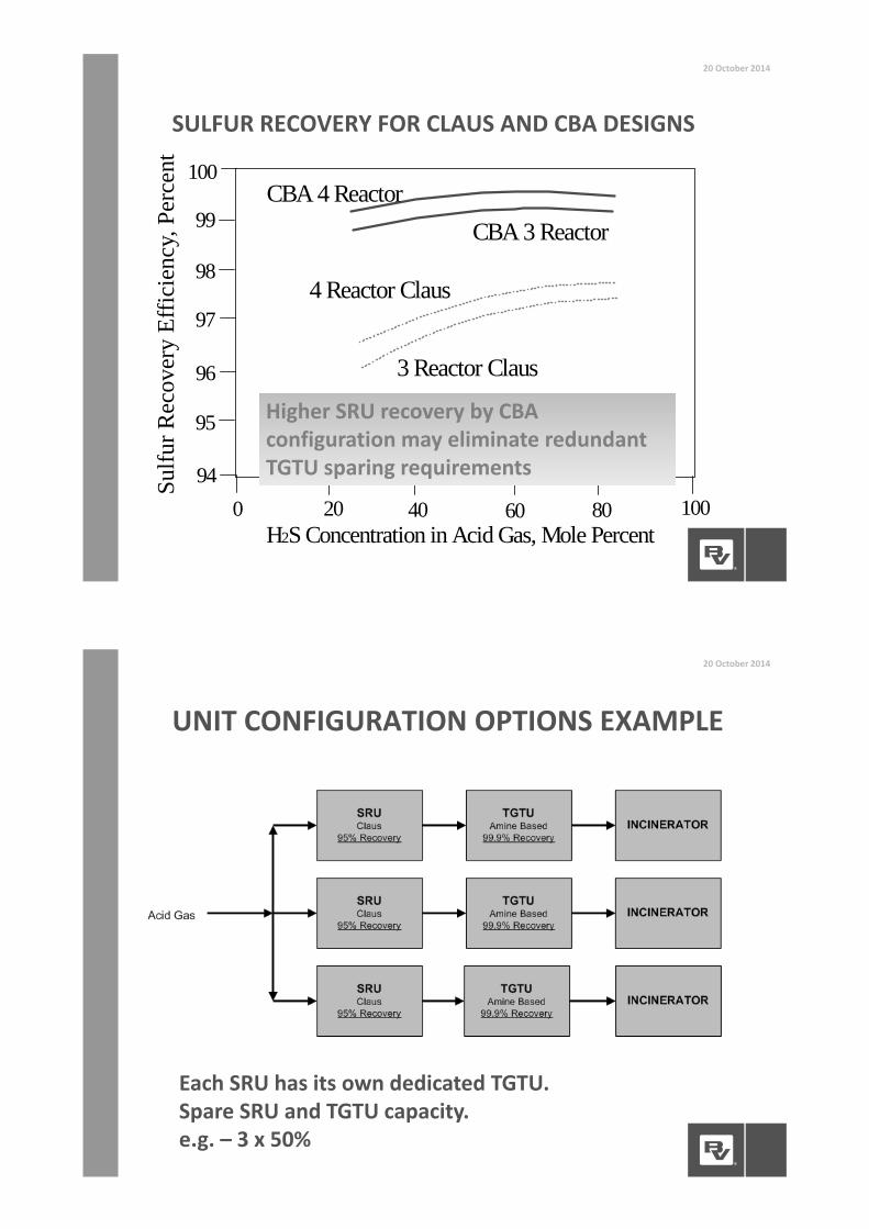
SULFUR RECOVERY FOR CLAUS AND CBA DESIGNS
20 October 2014
H2S Concentration in Acid Gas, Mole Percent
Sulfu
r Rec
over
y Ef
ficie
ncy,
Per
cent
0
96
98
100
40 8094
99
97
95
3 Reactor Claus
4 Reactor Claus
CBA 3 ReactorCBA 4 Reactor
20 60 100
Higher SRU recovery by CBAconfiguration may eliminate redundantTGTU sparing requirements
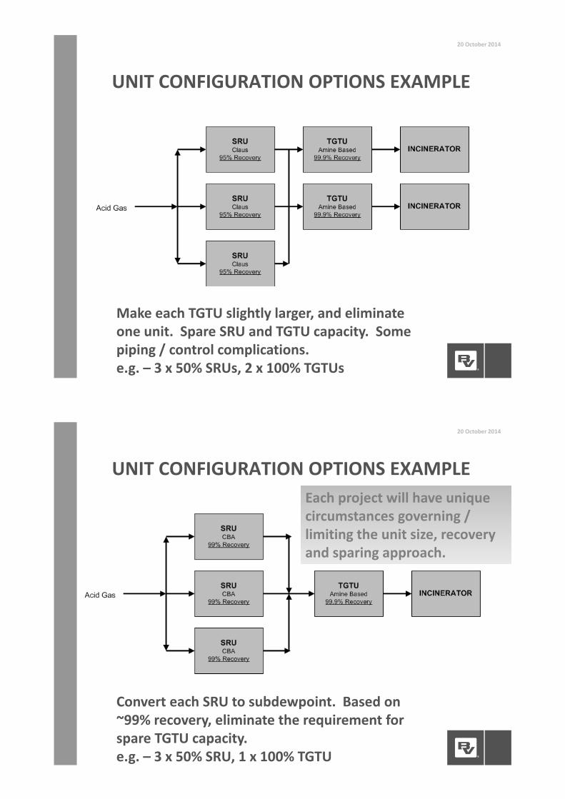
UNIT CONFIGURATION OPTIONS EXAMPLE
20 October 2014
Each SRU has its own dedicated TGTU.Spare SRU and TGTU capacity.e.g. – 3 x 50%
UNIT CONFIGURATION OPTIONS EXAMPLE
20 October 2014
Make each TGTU slightly larger, and eliminateone unit. Spare SRU and TGTU capacity. Somepiping / control complications.e.g. – 3 x 50% SRUs, 2 x 100% TGTUs
UNIT CONFIGURATION OPTIONS EXAMPLE
20 October 2014
Convert each SRU to subdewpoint. Based on~99% recovery, eliminate the requirement forspare TGTU capacity.e.g. – 3 x 50% SRU, 1 x 100% TGTU
Each project will have uniquecircumstances governing /limiting the unit size, recoveryand sparing approach.
ORGANIC SULFUR IN FEEDGAS
20October 2014
HOW OFTEN IS COS/RSH PRESENT INYOUR ACID GAS?
HOW DOES THIS IMPACT EMISSIONS,PARTICULARLY WITH ACID GASENRICHMENT?
DESI
GN
CHALL
ENGES
• For AGE facilities, COS and mercaptans (RSH) contributedirectly to emissions because they tend to slip throughAGE Absorber• COS comes from upstream AGRU that is normally designedto remove all COS (also coabsorbs abundant CO2)
• Mercaptans depend on upstream, AGRU solvent selectionand sophistication of model
• Predicting performance of organic sulfur absorption iscomplex and challenging, particularly at low pressuresand in the presence of H2S• Heavily dependent on accuracy of solvent vendorperformance data to meet emissions
ORGANIC SULFUR IN FEED GAS20 October 2014
Cannot decouple AGRU and SRU Performance!!
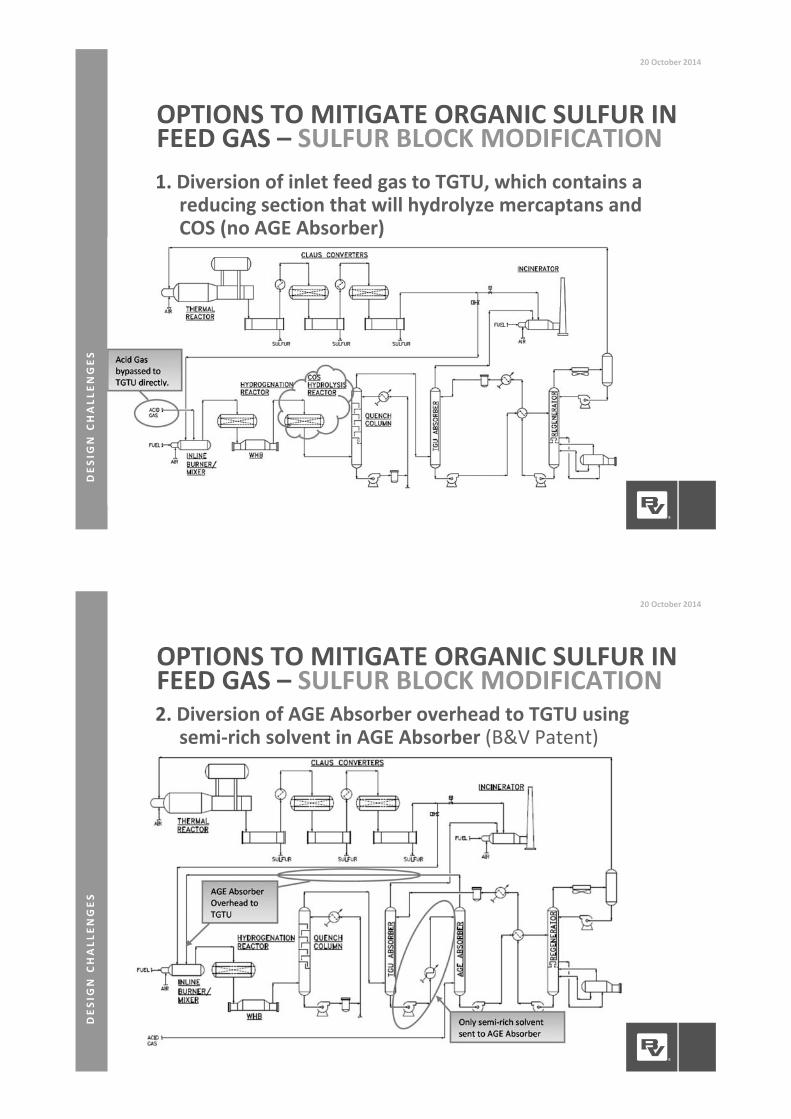
1. Diversion of inlet feed gas to TGTU, which contains areducing section that will hydrolyze mercaptans andCOS (no AGE Absorber)
OPTIONS TO MITIGATE ORGANIC SULFUR INFEED GAS – SULFUR BLOCK MODIFICATION
20October 2014
DESI
GN
CHALL
ENGES
2. Diversion of AGE Absorber overhead to TGTU usingsemi rich solvent in AGE Absorber (B&V Patent)
OPTIONS TO MITIGATE ORGANIC SULFUR INFEED GAS – SULFUR BLOCK MODIFICATION
20October 2014
DESI
GN
CHALL
ENGES
3. Interstage cooling and hydrolysis in the AGRU tomaximize CO2 slip and hydrolyze COS (B&V designfrom Sinopec Puguang Natural Gas Treating Project)
OPTIONS TO MITIGATE ORGANIC SULFUR INFEED GAS – UPSTREAMMODIFICATION
20October 2014
DESI
GN
CHALL
ENGES
4. Tail Gas Scrubbing (Caustic Scrubber)• Last resort if integration with AGRU or project optimizationcannot be achieved
• Challenges with tail gas scrubbing• Wastewater disposal or treatment• High alloy metallurgy• Cost (Opex) and delivery logistics of caustic
• Tail gas scrubbing represents a trade of air emissions forliquid emissions or costly wastewater treatment
OPTIONS TO MITIGATE ORGANIC SULFUR INFEED GAS – DOWNSTREAMMODIFICATION
20October 2014
DESI
GN
CHALL
ENGES
CONTAMINATED ACIDGAS
20October 2014
HOW OFTEN IS BTX A COMPONENT INACID GAS?
HAS IT BEEN A PROBLEM?
WHAT ARE YOUR MITIGATIONMEASURES?
• Uncertainty in BTX contained in Produced Gas• Uncertainty in BTX pickup by AGRU solvent• BTX has to be removed or destroyed prior to cominginto contact with any catalyst bed
• Lean acid gases often do not burn hot enough forsufficient BTX destruction in the SRU ThermalReactor
• In addition to ultra low emissions, some projects arerequiring a minimal level of SRU recovery• Requirements >95% will require 3rd catalytic stage or moreelaborate design
CONTAMINATED LEAN ACID GAS
20 October 2014
DESI
GN
CHALL
ENGES
• Often significant technical challenges and uncertaintywith lean acid gas feeds and ultra low emissions
• Sizeable commercial and operational impacts forachieving ultra low emissions
• Design optimization requires joint effort andcooperation between designers, end users andregulatory agencies
CONTAMINATED LEAN ACID GAS
20 October 2014
• Alternative options to destroy BTX• Thermal Reactor temperature enhancements:
• Co firing natural gas – not recommend, trades onecatalyst contaminant (BTX) for another (soot)
• Acid Gas Enrichment to improve acid gas quality• Upstream BTX removal – Sorbead™ Quick Cycleprocess (silica gel based absorbent that removes BTXwith heavier hydrocarbons, also removes mercaptans)
• Carbon beds upstream of SRU (developed by SaudiAramco)
BTX IN FEED GAS
20 October 2014
DESI
GN
CHALL
ENGES
DESIGN BASIS20October 2014
WHAT IS YOUR APPROACH TO SETTINGDESIGN PARAMETERS GAS TREATINGDURING EARLY PROJECTDEVELOPMENT?ARE YOU THINKING ABOUTCOS/RSH/BTX?WHAT ARE LONG TERMPERFORMANCE REQUIREMENTS?
DESI
GN
CHALL
ENGES
• Important components that need to be adequatelydefined:• Organic Sulfur Species – complicate achieving ultra lowemissions• Carbonyl Sulfide (COS) and/or mercaptans (RSH)
• Upstream modifications can reduce organic sulfur andBTX content in acid gas feed to SRU
• Being able to integrate and optimize upstreammodifications with SRU design is often complicated• It is difficult for SRU designed to influence overall design ofupstream units that may or may not be in SRU designersscope
• If design can be integrated and optimized across all unitinterfaces, it will result in an overall project WIN in termsof OPEX/CAPEX
DESIGN BASIS – UPSTREAMMODIFICATIONS
20 October 2014
DESI
GN
CHALL
ENGES
• Typically contractors focus on start of run (SOR)guarantees
• Projects with lean acid gases and ultra low emissionsmay have some exposure to performances shortcomingsat end of run (EOR)
• Technology provider and Owner should focus onmaximizing performance at EOR and not just meetingguarantees