Blade model for certification test support and failure prediction A G Dutton, M Clarke 1 , P Bonnet 2 Energy Research Unit (ERU) Rutherford Appleton Laboratory (RAL) Science and Technology Facilities Council (STFC) (now at 1 Oxford Brookes University and 2 SAMTECH Iberica) Supergen Wind Final Assembly Holywell Park, Loughborough University 25 March 2010
Transcript
Blade model for certification test support and
failure prediction
A G Dutton, M Clarke1, P Bonnet2
Energy Research Unit (ERU)
Rutherford Appleton Laboratory (RAL)
Science and Technology Facilities Council (STFC)(now at 1Oxford Brookes University and 2SAMTECH Iberica)
Supergen Wind Final Assembly
Holywell Park, Loughborough University
25 March 2010
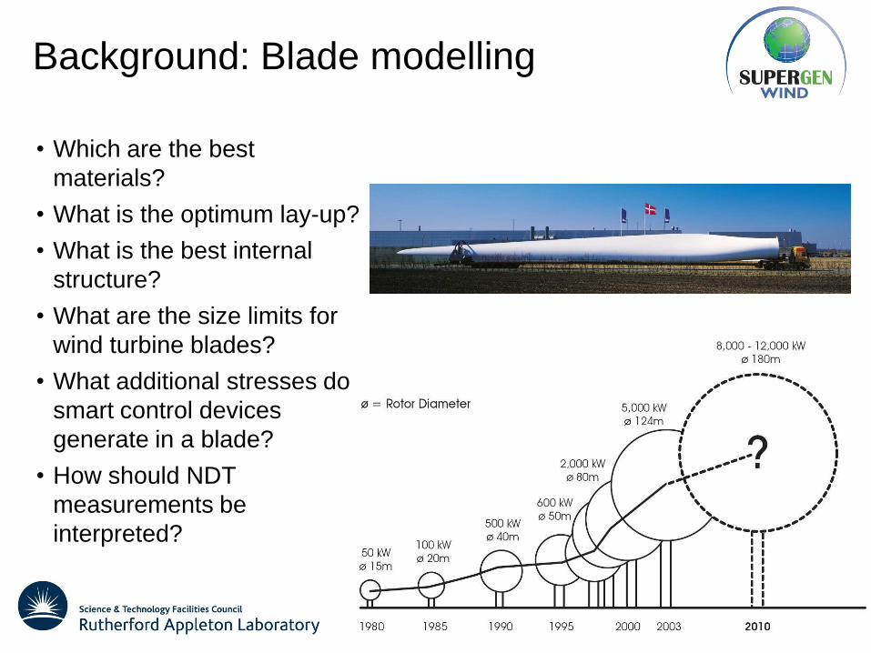
Background: Blade modelling
• Which are the best
materials?
• What is the optimum lay-up?
• What is the best internal
structure?
• What are the size limits for
wind turbine blades?
• What additional stresses do
smart control devices
generate in a blade?
• How should NDT
measurements be
interpreted?
Parametric blade model:
Design strategy
• Parametric processing tool for creation and running of the underlying FE
model
• Suitable for sensitivity analyses, flexibility, documenting, re-usability
Python script front end for automation of the Abaqus FE package
Modular program
Realistic load application, including quasi-static aerodynamic loading
Ultimate strength & fatigue analysis
Developing dynamic implementation
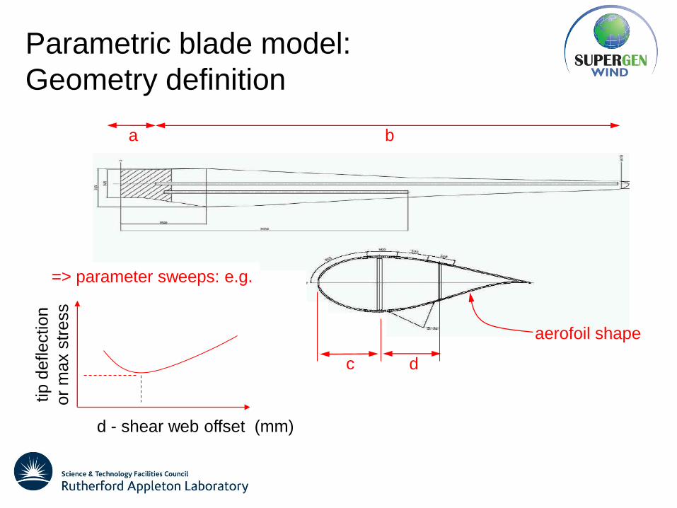
Parametric blade model:
Geometry definition
a b
c d
aerofoil shape
=> parameter sweeps: e.g.
tip
deflection
or
max s
tress
d - shear web offset (mm)
Parametric blade model:
Geometry definition
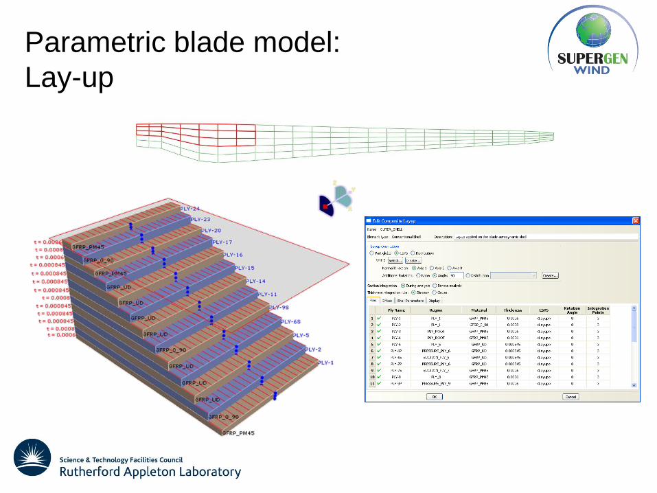
Parametric blade model:
Lay-up
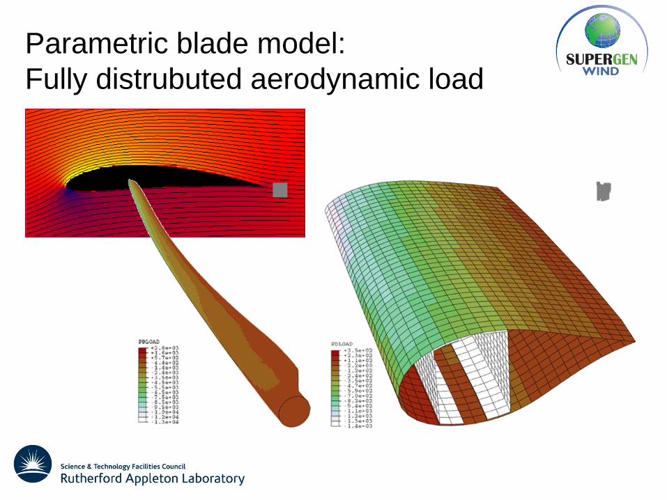
Parametric blade model:
Fully distrubuted aerodynamic load
Parametric blade model:
Variable mesh density...
... at the push of a button
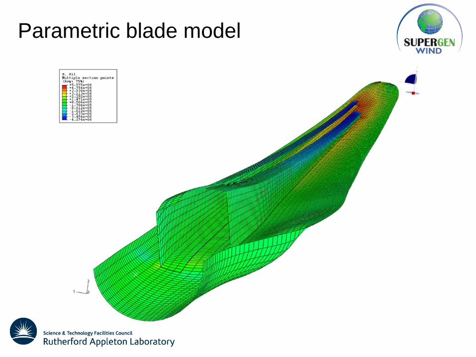
Parametric blade model
5 MW (61 m) blade model
• Basic lay-up information
• Target mass and stiffness distributions
• Limitations of lay-up information
• Overall mass
• Discretisation of lay-up info
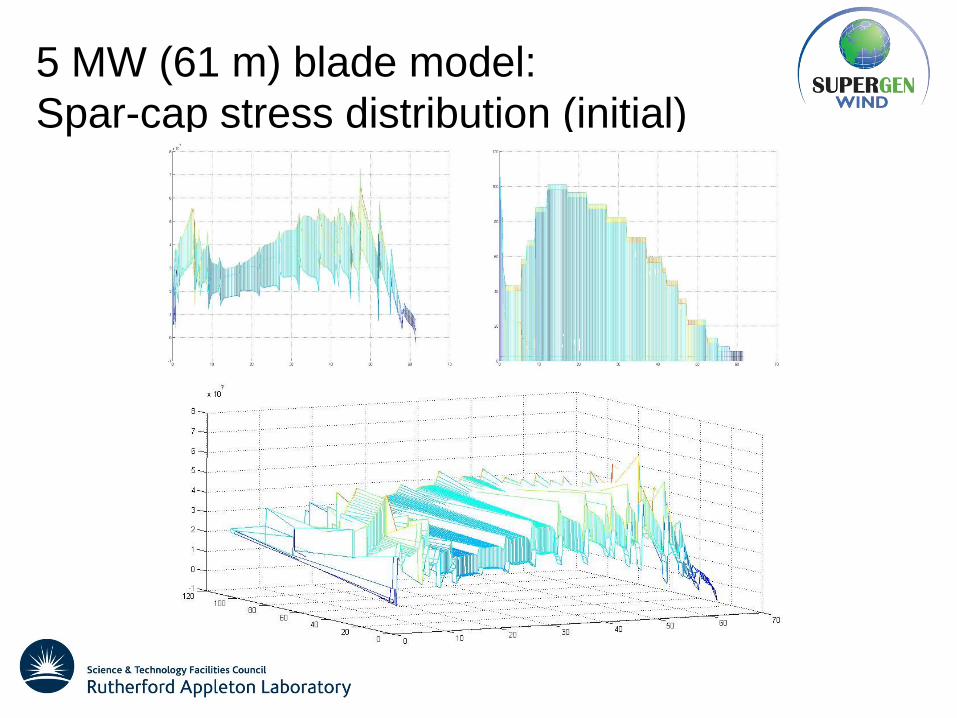
• Required spar-cap stress profile?
• Lay-up modification
• Materials variation
• Static load case (aerodynamic load distribution)
• Fatigue lifetime
5 MW (61 m) blade model:
Spar-cap stress distribution (initial)
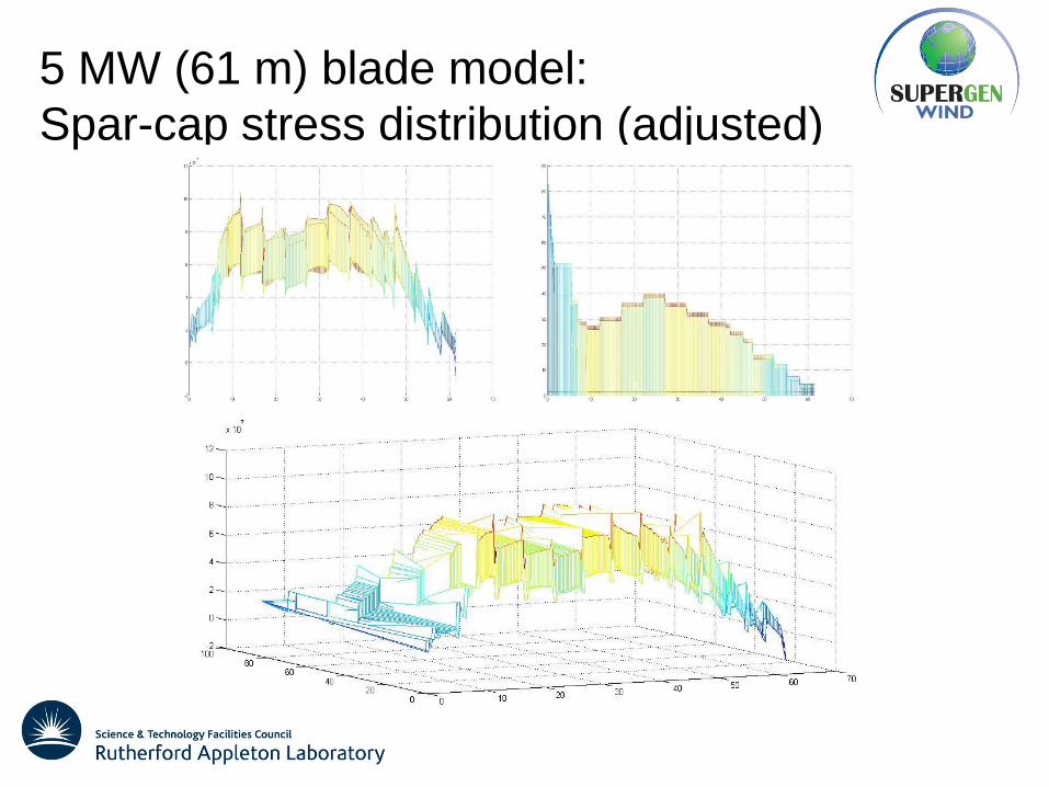
5 MW (61 m) blade model:
Spar-cap stress distribution (adjusted)
5 MW (61 m) blade model:
Spar-cap stress distribution (smoothed)
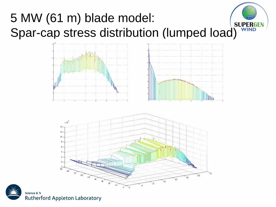
5 MW (61 m) blade model:
Spar-cap stress distribution (lumped load)
5 MW (61 m) blade model:
Materials
Baseline UD
material
Mean value
E1T (GPa) 39.042
E1C (GPa) 38.91
ν120.29058
E2T (GPa) 14.077
E2C (GPa) 14.997
ν210.95036E-01
G12 (MPa) 4.2388
Baseline UD
material
Mean value
XT (MPa) 776.5
XC (MPa) -521.82
YT (MPa) 53.865
YC (MPa) -165
S (MPa) 56.071
5 MW (61 m) blade model:
Static and fatigue failure
kd fFn m
k f
1 F
“Design” load
Characteristic
value of
material
property
Characteristic
load
Partial safety
factors
Loads
Material
Consequences
of failure
Design guidelines:
• ISO 61400-1
• Germanischer Lloyd (GL)
• Det Norske Veritas (DNV)
Range of design load cases:
• Ultimate
• Fatigue
5 MW (61 m) blade model:
Static strength – skins and shear web
Choice of static failure
criteria:
• Tsai-Wu
• Tsai-Hill
• Other (user specified)
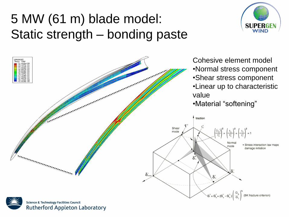
5 MW (61 m) blade model:
Static strength – bonding paste
Cohesive element model
•Normal stress component
•Shear stress component
•Linear up to characteristic
value
•Material “softening”
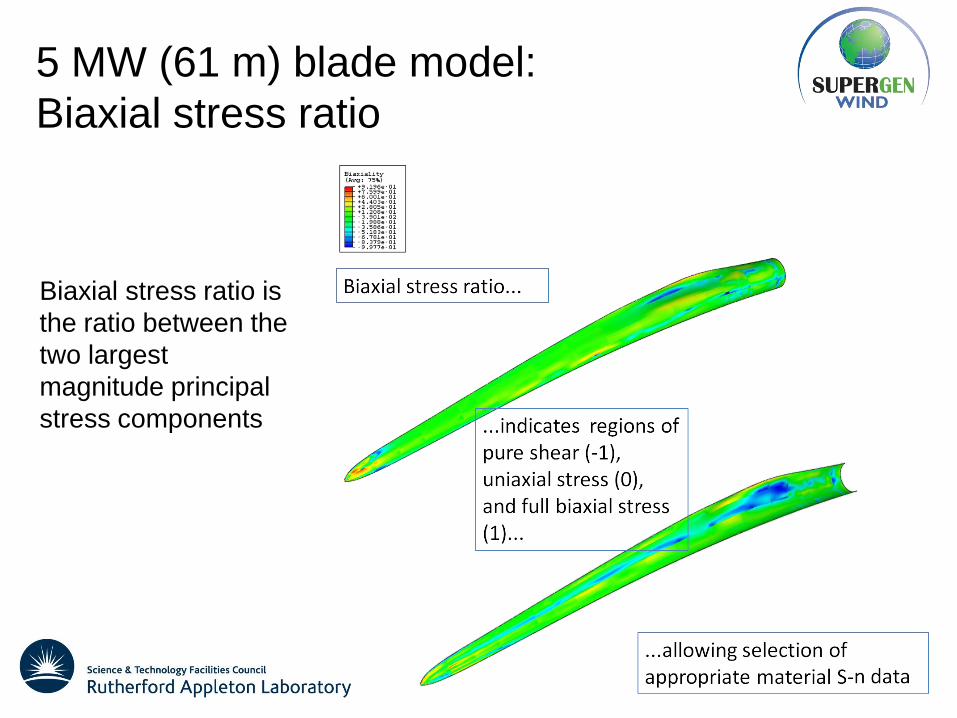
5 MW (61 m) blade model:
Biaxial stress ratio
Biaxial stress ratio is
the ratio between the
two largest
magnitude principal
stress components
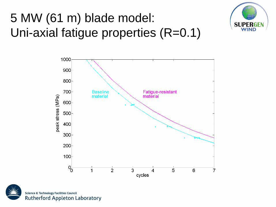
5 MW (61 m) blade model:
Uni-axial fatigue properties (R=0.1)
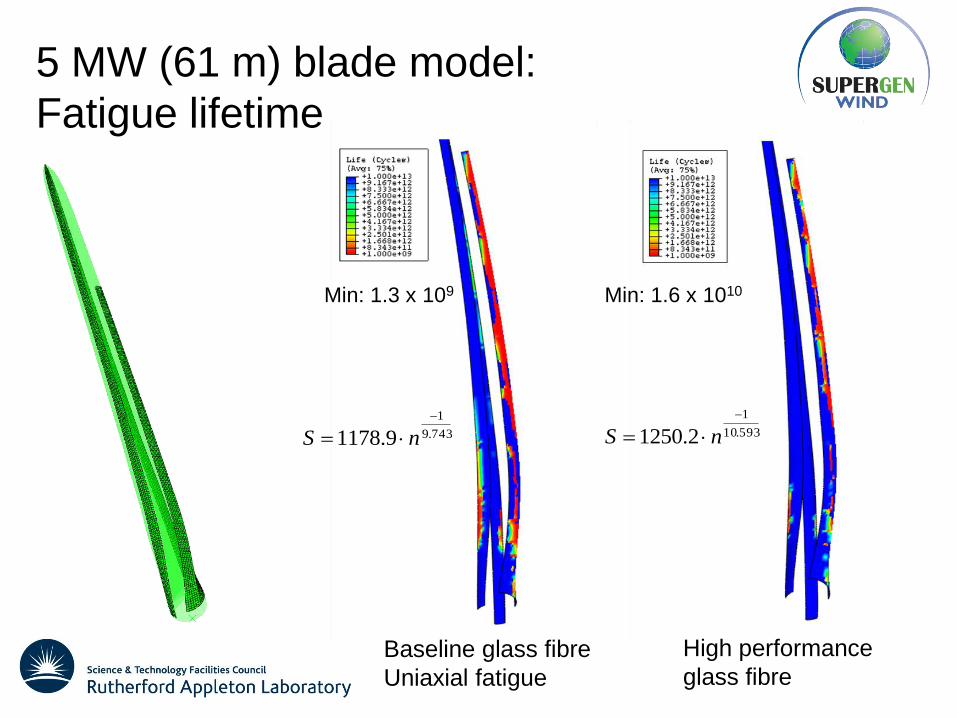
5 MW (61 m) blade model:
Fatigue lifetime
Baseline glass fibre
Uniaxial fatigue
743.9
1
9.1178
nS
Min: 1.3 x 10⁹
593.10
1
2.1250
nS
High performance
glass fibre
Min: 1.6 x 10¹⁰
Full scale blade testing
Multi-axial loading validation
Full scale blade testing
Multi-axial loading validation
-8
-6
-4
-2
0
2
4
6
8
-1.5
Tip
Fla
pw
ise
De
fle
cti
on
s (
m)
Tip Edgewise Deflections (m)
Blade model
Experimental data
(courtesy NAREC)
Full scale blade testing
Thermoelastic stress analysis
Blade test: blade with defects
2211
pc
TTIsotropic materials:
Orthotropic materials: 22221111
pc
TT
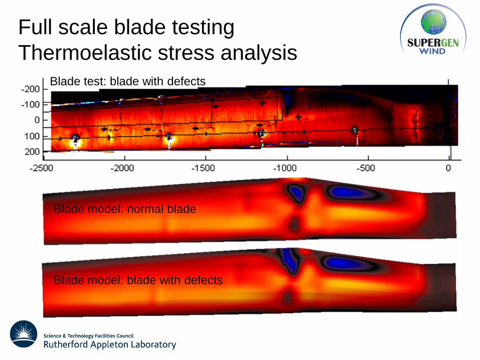
Full scale blade testing
Thermoelastic stress analysis
Blade test: blade with defects
Blade model: normal blade
Blade model: blade with defects
Conclusions
• Flexible, parametric blade model for assessment of alternative
materials with enhanced static and fatigue properties
• Initial results also available for application to full-scale blade testing,
control of smart blades and interpretation of condition monitoring data
• Future work planned on dynamic loading – operation in wakes from


![Turbine blade temperature calculation and life estimation ... · (HCF). Castillo et al. [25] also performed a similar blade failure investigation for another gas turbine blade. Their](https://static.documents.pub/doc/80x56/5f559abf2cad2e751d2bdd57/turbine-blade-temperature-calculation-and-life-estimation-hcf-castillo-et.jpg)


