65
Building Head and Neck Anatomical Atlas for Robust Image Segmentation using Statistical Models Olivier COMMOWICK, CRL, Childrens Hospital Boston. June 17, 2009.
Building Head and Neck Anatomical Atlas for Robust Image Segmentation using
Statistical Models
Olivier COMMOWICK,CRL, Childrens Hospital Boston.
June 17, 2009.
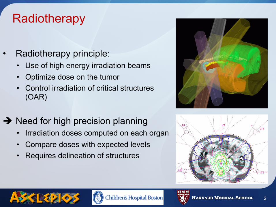
Radiotherapy
• Radiotherapy principle:• Use of high energy irradiation beams • Optimize dose on the tumor• Control irradiation of critical structures
(OAR)
Need for high precision planning• Irradiation doses computed on each organ• Compare doses with expected levels• Requires delineation of structures
2
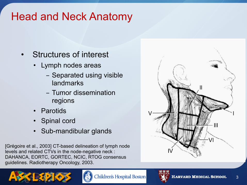
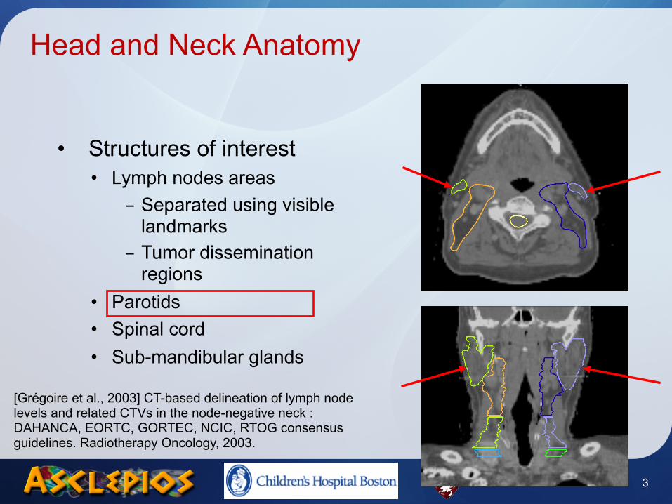
Head and Neck Anatomy
• Structures of interest• Lymph nodes areas
- Separated using visible landmarks
- Tumor dissemination regions
• Parotids• Spinal cord• Sub-mandibular glands
[Grégoire et al., 2003] CT-based delineation of lymph node levels and related CTVs in the node-negative neck : DAHANCA, EORTC, GORTEC, NCIC, RTOG consensus guidelines. Radiotherapy Oncology, 2003.
3
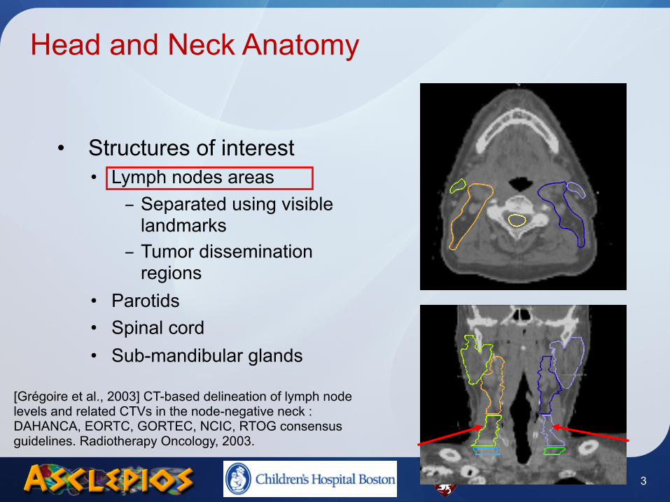
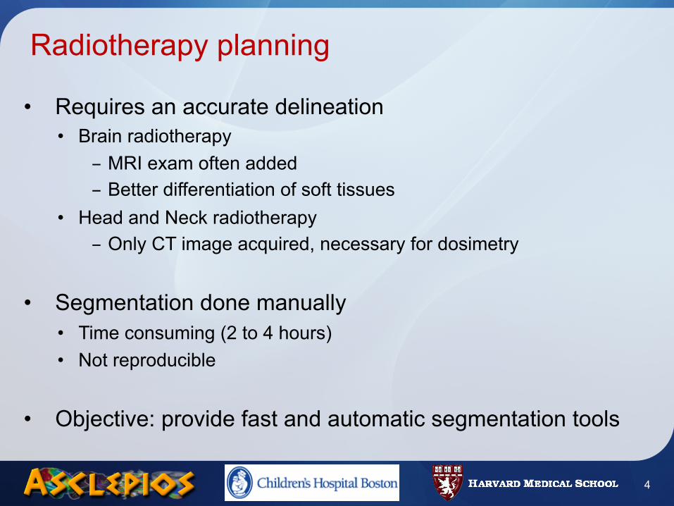
Radiotherapy planning
• Requires an accurate delineation• Brain radiotherapy
- MRI exam often added- Better differentiation of soft tissues
• Head and Neck radiotherapy- Only CT image acquired, necessary for dosimetry
• Segmentation done manually• Time consuming (2 to 4 hours)• Not reproducible
• Objective: provide fast and automatic segmentation tools
4
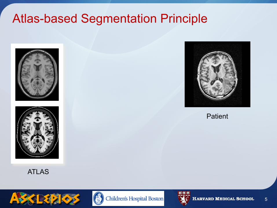
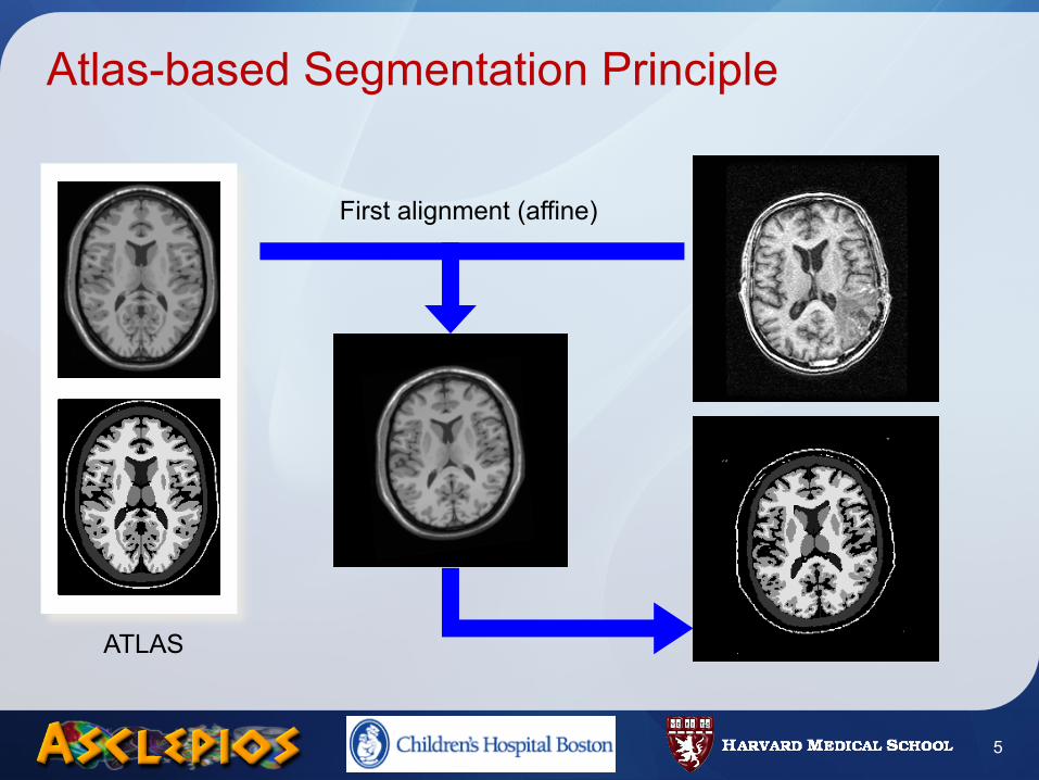
Atlas-based Segmentation Principle
5
Patient
ATLAS
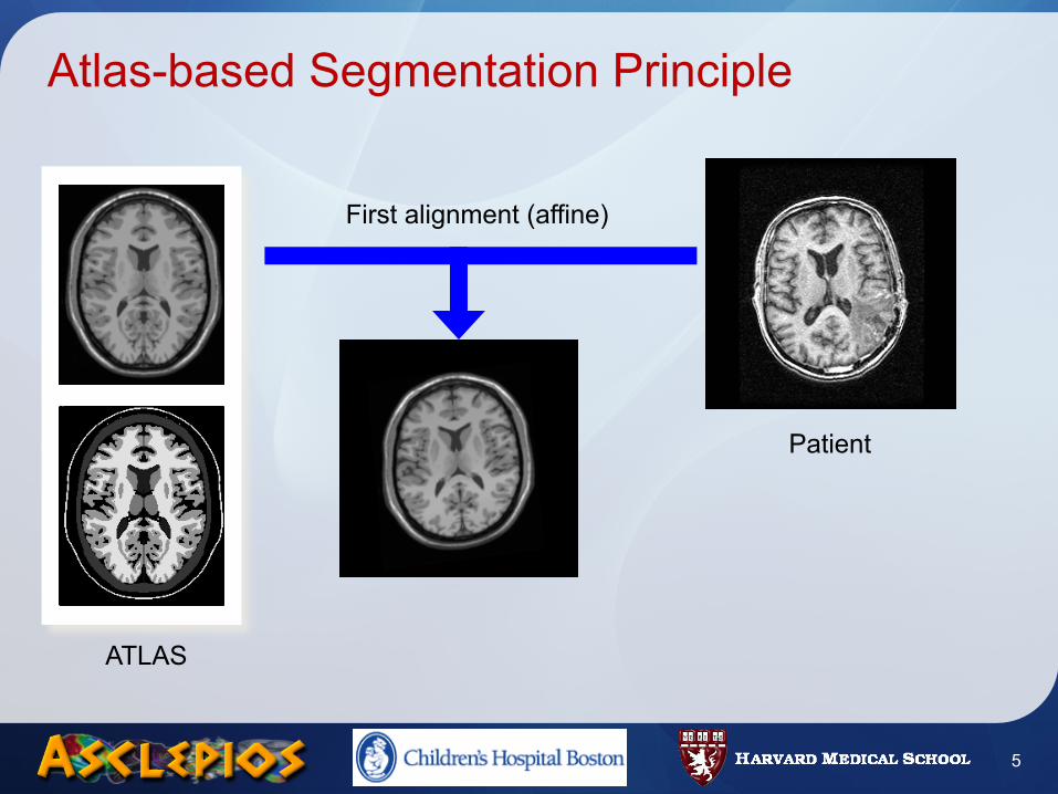
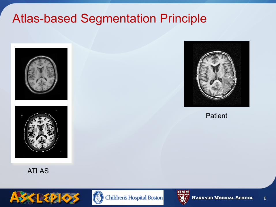
Atlas-based Segmentation Principle
5
Patient
ATLAS
First alignment (affine)
Atlas-based Segmentation Principle
5
Patient
ATLAS
First alignment (affine)
Atlas-based Segmentation Principle
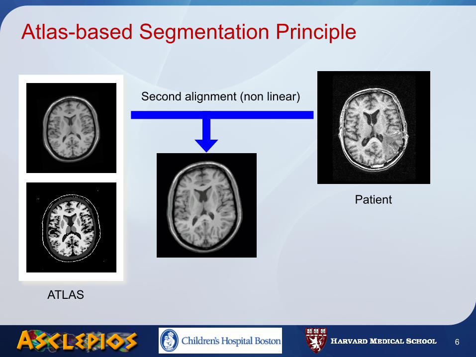
6
Patient
ATLAS
Atlas-based Segmentation Principle
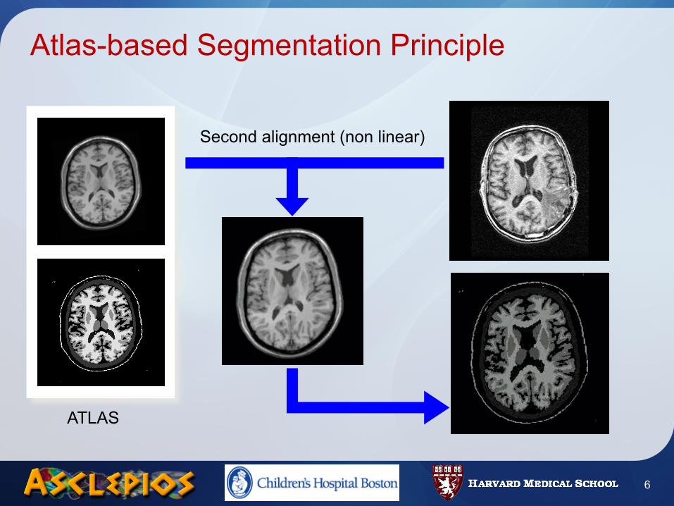
6
Patient
ATLAS
Second alignment (non linear)
Atlas-based Segmentation Principle
6
Patient
ATLAS
Second alignment (non linear)
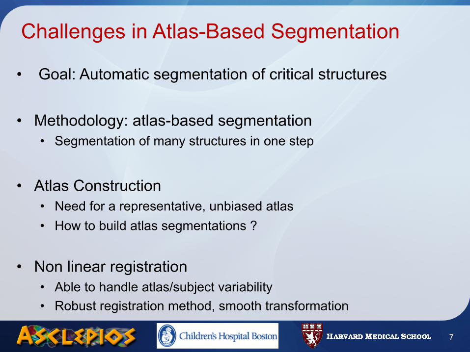
Challenges in Atlas-Based Segmentation
• Goal: Automatic segmentation of critical structures
• Methodology: atlas-based segmentation• Segmentation of many structures in one step
• Atlas Construction• Need for a representative, unbiased atlas• How to build atlas segmentations ?
• Non linear registration• Able to handle atlas/subject variability• Robust registration method, smooth transformation
7
Road Map
• Introduction• Methods
• Atlas Construction• Locally Affine Registration• Average Segmentations Construction
• Results• Registration validation• Head and Neck Atlas Construction
• Conclusion
8
Road Map
• Introduction• Methods
• Atlas Construction• Locally Affine Registration• Average Segmentations Construction
• Results• Registration validation• Head and Neck Atlas Construction
• Conclusion
9
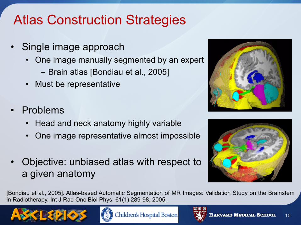
Atlas Construction Strategies
• Single image approach• One image manually segmented by an expert
- Brain atlas [Bondiau et al., 2005]• Must be representative
• Problems• Head and neck anatomy highly variable• One image representative almost impossible
• Objective: unbiased atlas with respect to a given anatomy
10
[Bondiau et al., 2005]. Atlas-based Automatic Segmentation of MR Images: Validation Study on the Brainstem in Radiotherapy. Int J Rad Onc Biol Phys, 61(1):289-98, 2005.
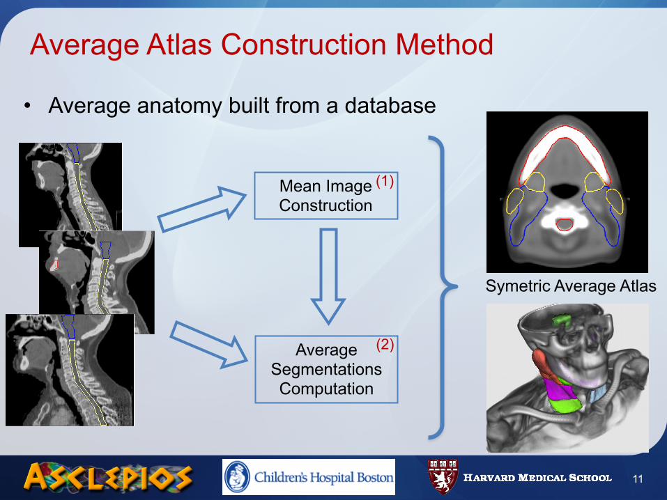
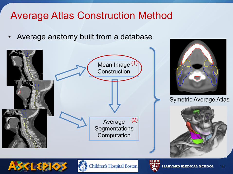
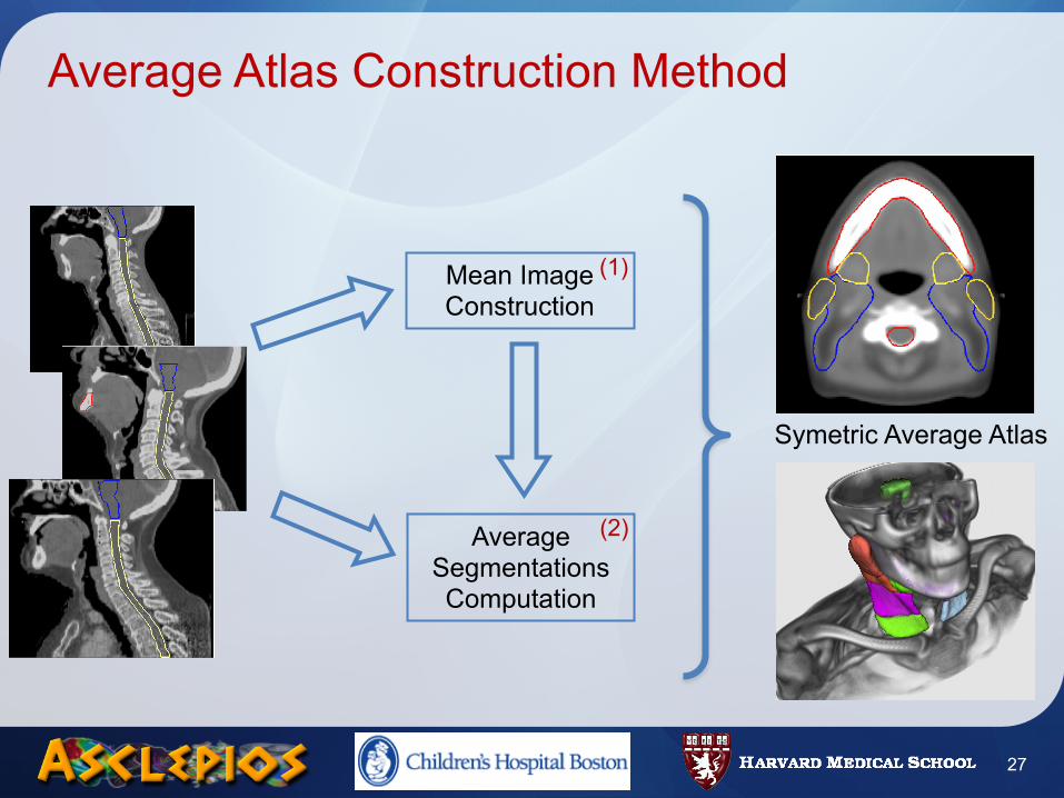
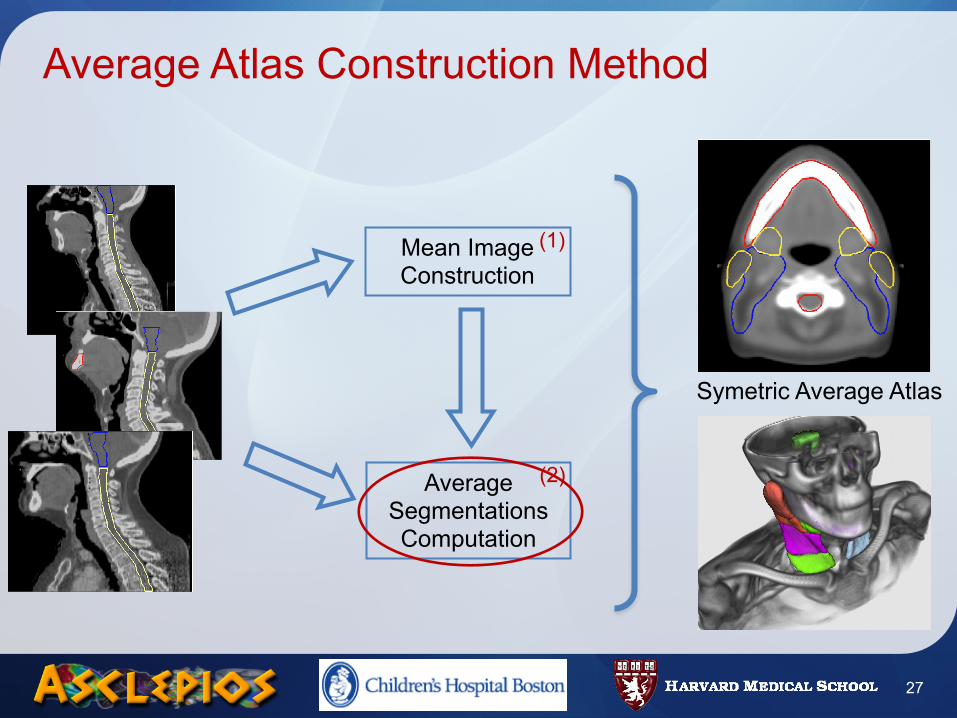
• Average anatomy built from a database
Average Atlas Construction Method
11
Mean Image Construction
Average Segmentations Computation
(1)
(2)
Symetric Average Atlas
• Average anatomy built from a database
Average Atlas Construction Method
11
Mean Image Construction
Average Segmentations Computation
(1)
(2)
Symetric Average Atlas
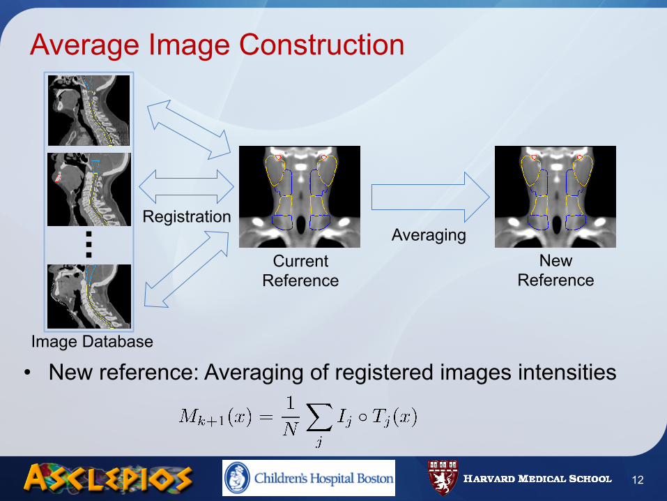
Average Image Construction
• New reference: Averaging of registered images intensities
12
Image Database
Registration
Current Reference
New Reference
Averaging
Average Image Construction
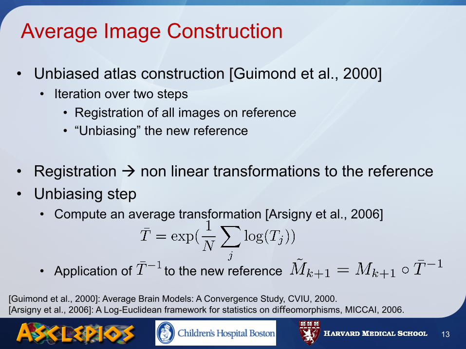
• Unbiased atlas construction [Guimond et al., 2000]• Iteration over two steps
• Registration of all images on reference• “Unbiasing” the new reference
• Registration non linear transformations to the reference• Unbiasing step
• Compute an average transformation [Arsigny et al., 2006]
• Application of to the new reference
[Guimond et al., 2000]: Average Brain Models: A Convergence Study, CVIU, 2000.[Arsigny et al., 2006]: A Log-Euclidean framework for statistics on diffeomorphisms, MICCAI, 2006.
13
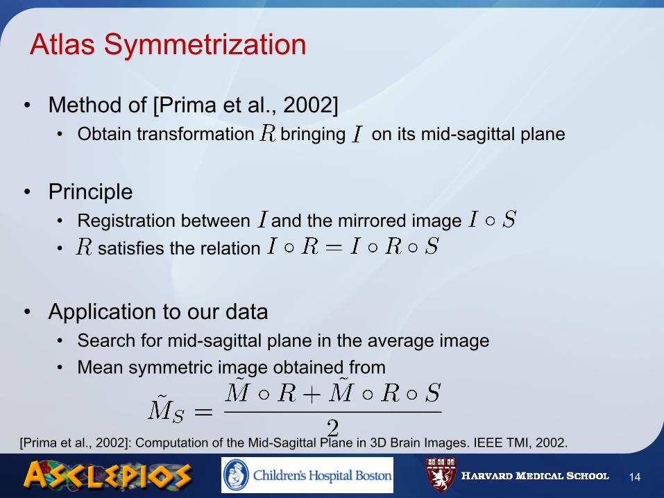
Atlas Symmetrization
• Method of [Prima et al., 2002]• Obtain transformation bringing on its mid-sagittal plane
• Principle• Registration between and the mirrored image• satisfies the relation
• Application to our data• Search for mid-sagittal plane in the average image• Mean symmetric image obtained from
14
[Prima et al., 2002]: Computation of the Mid-Sagittal Plane in 3D Brain Images. IEEE TMI, 2002.
Summary
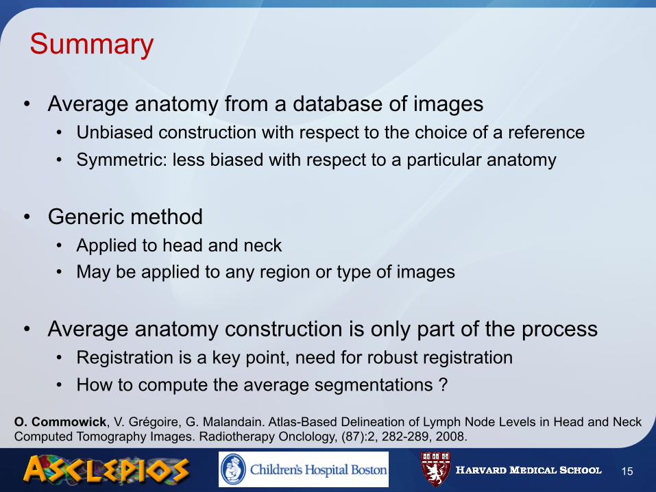
• Average anatomy from a database of images• Unbiased construction with respect to the choice of a reference• Symmetric: less biased with respect to a particular anatomy
• Generic method• Applied to head and neck• May be applied to any region or type of images
• Average anatomy construction is only part of the process• Registration is a key point, need for robust registration• How to compute the average segmentations ?
15
O. Commowick, V. Grégoire, G. Malandain. Atlas-Based Delineation of Lymph Node Levels in Head and Neck Computed Tomography Images. Radiotherapy Onclology, (87):2, 282-289, 2008.
Road Map
• Introduction• Methods
• Atlas Construction• Locally Affine Registration• Average Segmentations Construction
• Results• Registration validation• Head and Neck Atlas Construction
• Conclusion
16
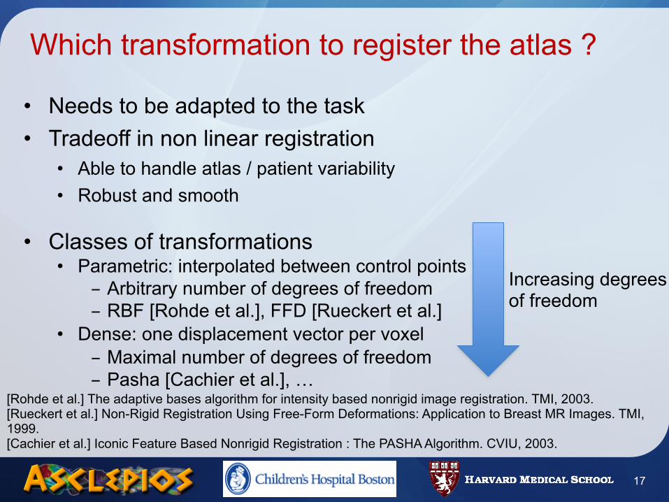
Which transformation to register the atlas ?
• Needs to be adapted to the task• Tradeoff in non linear registration
• Able to handle atlas / patient variability• Robust and smooth
• Classes of transformations• Parametric: interpolated between control points
- Arbitrary number of degrees of freedom- RBF [Rohde et al.], FFD [Rueckert et al.]
• Dense: one displacement vector per voxel- Maximal number of degrees of freedom- Pasha [Cachier et al.], …
17
[Rohde et al.] The adaptive bases algorithm for intensity based nonrigid image registration. TMI, 2003.[Rueckert et al.] Non-Rigid Registration Using Free-Form Deformations: Application to Breast MR Images. TMI, 1999.[Cachier et al.] Iconic Feature Based Nonrigid Registration : The PASHA Algorithm. CVIU, 2003.
Increasing degrees of freedom
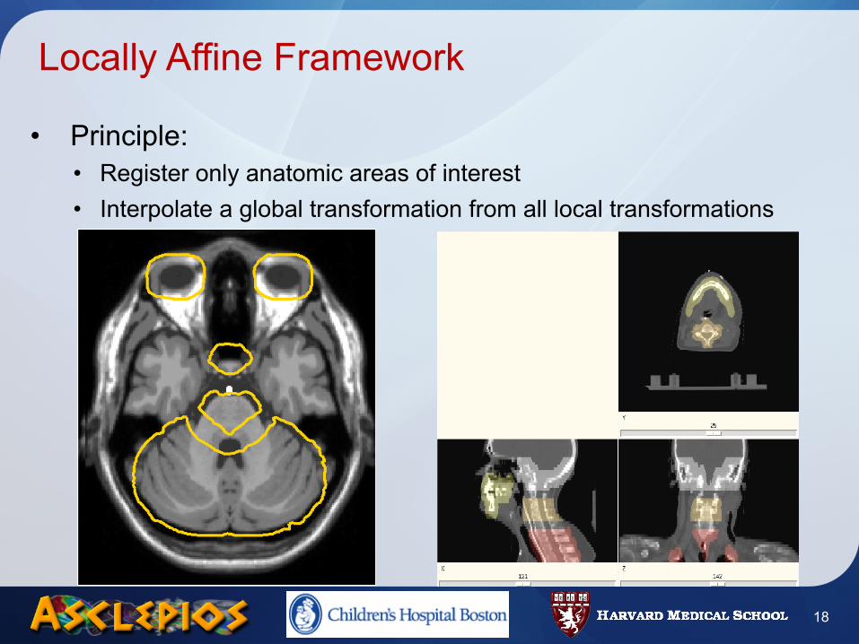
Locally Affine Framework
• Principle:• Register only anatomic areas of interest• Interpolate a global transformation from all local transformations
18
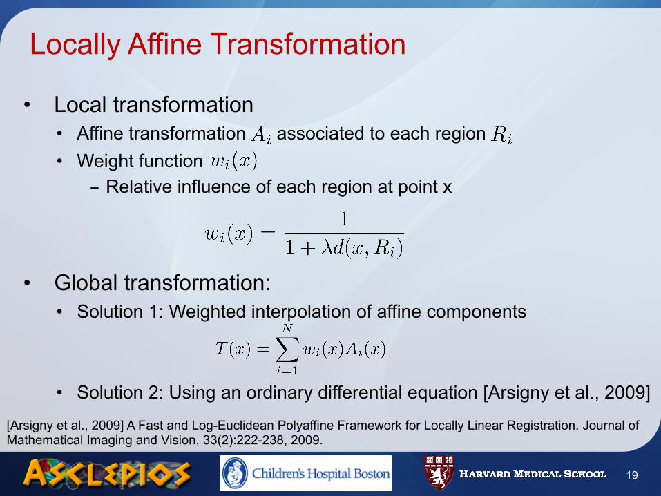
Locally Affine Transformation
• Local transformation• Affine transformation associated to each region• Weight function
- Relative influence of each region at point x
• Global transformation:• Solution 1: Weighted interpolation of affine components
• Solution 2: Using an ordinary differential equation [Arsigny et al., 2009]
19
[Arsigny et al., 2009] A Fast and Log-Euclidean Polyaffine Framework for Locally Linear Registration. Journal of Mathematical Imaging and Vision, 33(2):222-238, 2009.
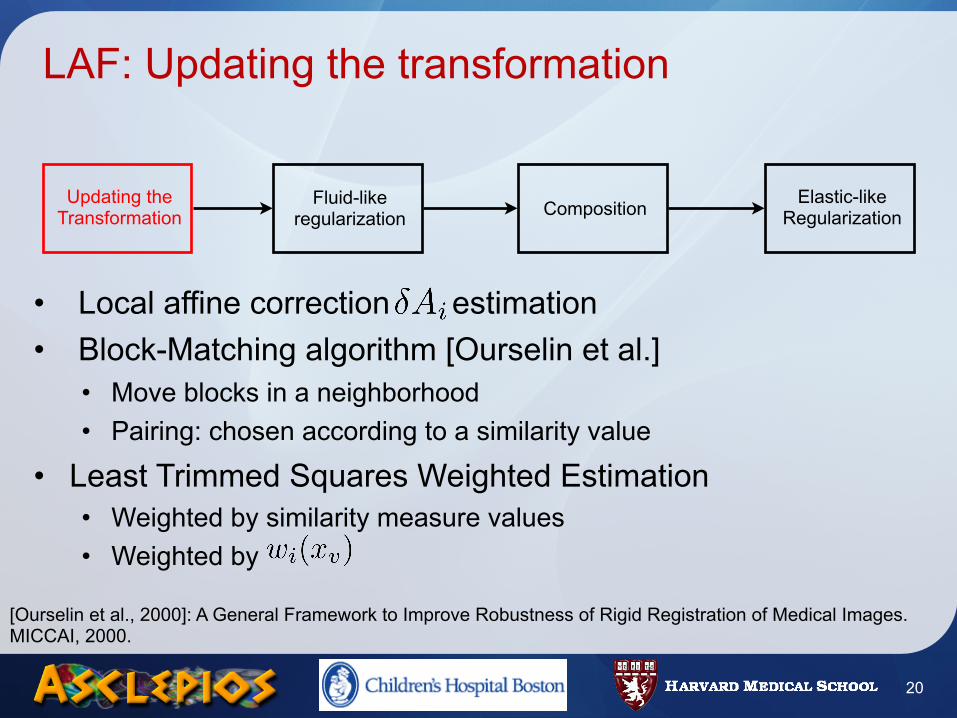
LAF: Updating the transformation
• Local affine correction estimation• Block-Matching algorithm [Ourselin et al.]
• Move blocks in a neighborhood• Pairing: chosen according to a similarity value
• Least Trimmed Squares Weighted Estimation• Weighted by similarity measure values• Weighted by
20
Updating the Transformation
Fluid-like regularization Composition Elastic-like
Regularization
[Ourselin et al., 2000]: A General Framework to Improve Robustness of Rigid Registration of Medical Images. MICCAI, 2000.
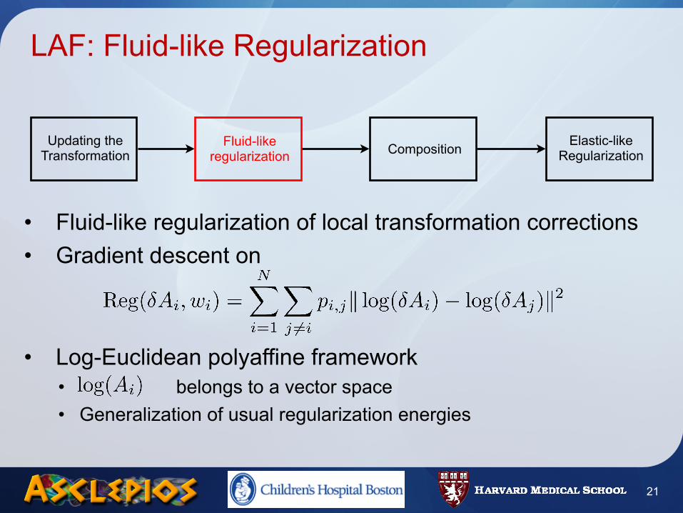
LAF: Fluid-like Regularization
• Fluid-like regularization of local transformation corrections• Gradient descent on
• Log-Euclidean polyaffine framework• belongs to a vector space• Generalization of usual regularization energies
21
Updating the Transformation
Fluid-like regularization Composition Elastic-like
Regularization
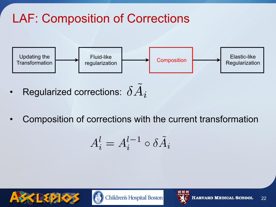
LAF: Composition of Corrections
• Regularized corrections:
• Composition of corrections with the current transformation
22
Updating the Transformation
Fluid-like regularization Composition Elastic-like
Regularization
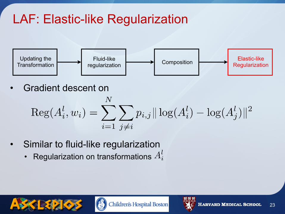
LAF: Elastic-like Regularization
• Gradient descent on
• Similar to fluid-like regularization• Regularization on transformations
23
Updating the Transformation
Fluid-like regularization Composition Elastic-like
Regularization
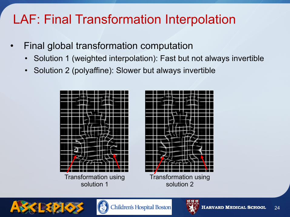
LAF: Final Transformation Interpolation
• Final global transformation computation• Solution 1 (weighted interpolation): Fast but not always invertible• Solution 2 (polyaffine): Slower but always invertible
24
Transformation using solution 1
Transformation using solution 2
Summary
• Locally Affine Registration [Commowick et al., 2008]• Constrained transformation• Log-Euclidean regularization and interpolation [Arsigny et al., 2009]• Robust registration
- One parameter set for all tested acquisition protocols• Fast computation time (10 minutes)
• Registration method able to recover large displacements• Ideal for articulated structures (head and neck)
25
[Commowick et al., 2008]: An Efficient Locally Affine Framework for the Smooth Registration of Anatomical Structures. Medical Image Analysis,12(4):427-441, 2008.[Arsigny et al., 2009] A Fast and Log-Euclidean Polyaffine Framework for Locally Linear Registration. JMIV, 33(2), 222-238, 2009.
Road Map
• Introduction• Methods
• Atlas Construction• Locally Affine Registration• Average Segmentations Construction
• Results• Registration validation• Head and Neck Atlas Construction
• Conclusion
26
Average Atlas Construction Method
27
Mean Image Construction
Average Segmentations Computation
(1)
(2)
Symetric Average Atlas
Average Atlas Construction Method
27
Mean Image Construction
Average Segmentations Computation
(1)
(2)
Symetric Average Atlas
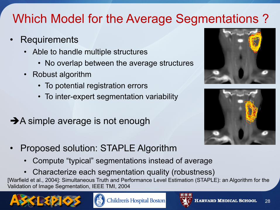
Which Model for the Average Segmentations ?• Requirements
• Able to handle multiple structures• No overlap between the average structures
• Robust algorithm• To potential registration errors• To inter-expert segmentation variability
A simple average is not enough
• Proposed solution: STAPLE Algorithm• Compute “typical” segmentations instead of average• Characterize each segmentation quality (robustness)
28
[Warfield et al., 2004]: Simultaneous Truth and Performance Level Estimation (STAPLE): an Algorithm for the Validation of Image Segmentation, IEEE TMI, 2004
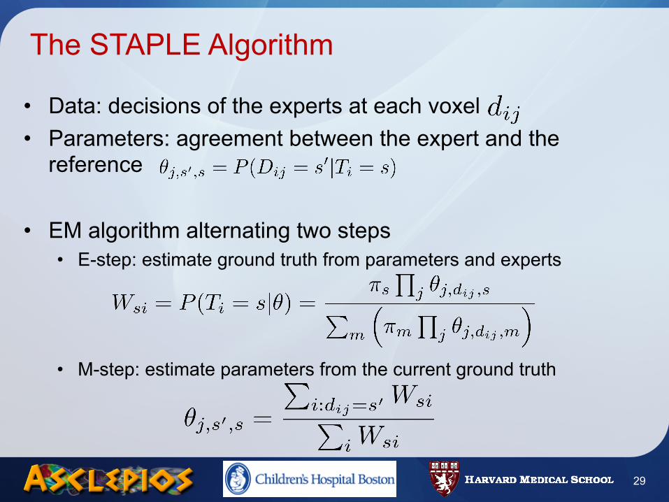
The STAPLE Algorithm
• Data: decisions of the experts at each voxel• Parameters: agreement between the expert and the
reference
• EM algorithm alternating two steps• E-step: estimate ground truth from parameters and experts
• M-step: estimate parameters from the current ground truth
29
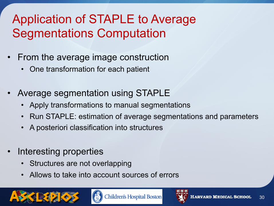
Application of STAPLE to Average Segmentations Computation
• From the average image construction• One transformation for each patient
• Average segmentation using STAPLE• Apply transformations to manual segmentations• Run STAPLE: estimation of average segmentations and parameters• A posteriori classification into structures
• Interesting properties• Structures are not overlapping• Allows to take into account sources of errors
30
Road Map
• Introduction• Methods
• Atlas Construction• Locally Affine Registration• Average Segmentations Construction
• Results• Registration validation• Head and Neck Atlas Construction
• Conclusion
31
Evaluation Methodology
• Databases• Image database from CAL Nice (Dr. PY Bondiau)
• Research quality, 1.5T, 2 mm slice thickness• Image database from IGR, Villejuif (Pr. V. Grégoire)
• Clinical quality, 1.5T, 3mm slice thickness• Injected with contrast agent
• Two evaluation methods• Visual inspection (CAL and IGR databases)• Semi-quantitative validation (IGR database)
- Visual inspection by a clinician- Graduation between 0 and 5
32
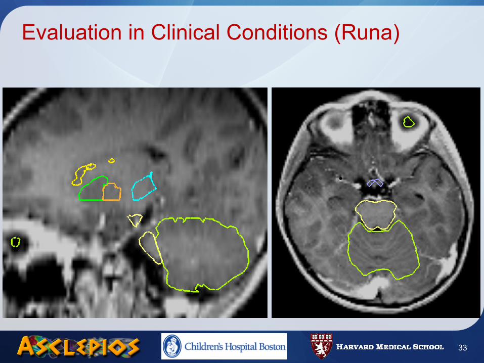
Evaluation in Clinical Conditions (Runa)
33
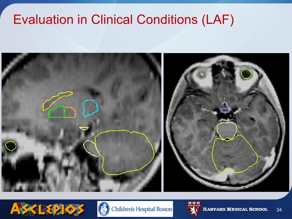
Evaluation in Clinical Conditions (LAF)
34
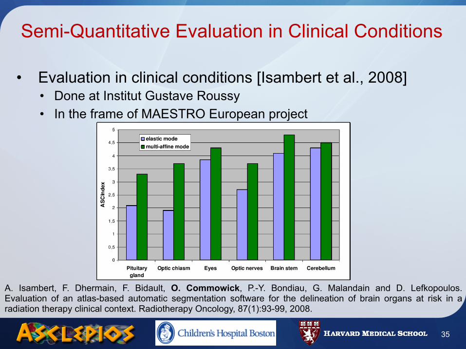
Semi-Quantitative Evaluation in Clinical Conditions
• Evaluation in clinical conditions [Isambert et al., 2008]• Done at Institut Gustave Roussy• In the frame of MAESTRO European project
A. Isambert, F. Dhermain, F. Bidault, O. Commowick, P.-Y. Bondiau, G. Malandain and D. Lefkopoulos. Evaluation of an atlas-based automatic segmentation software for the delineation of brain organs at risk in a radiation therapy clinical context. Radiotherapy Oncology, 87(1):93-99, 2008.
35
Road Map
• Introduction• Methods
• Atlas Construction• Locally Affine Registration• Average Segmentations Construction
• Results• Registration validation• Head and Neck Atlas Construction
• Conclusion
36
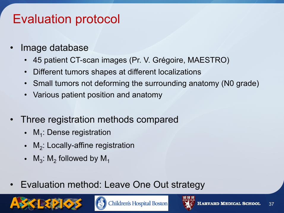
Evaluation protocol
• Image database• 45 patient CT-scan images (Pr. V. Grégoire, MAESTRO)• Different tumors shapes at different localizations• Small tumors not deforming the surrounding anatomy (N0 grade)• Various patient position and anatomy
• Three registration methods compared• M1: Dense registration
• M2: Locally-affine registration
• M3: M2 followed by M1
• Evaluation method: Leave One Out strategy
37
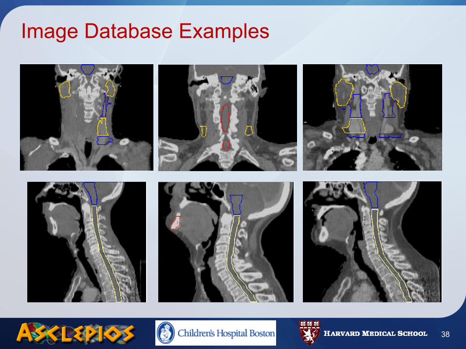
Image Database Examples
38
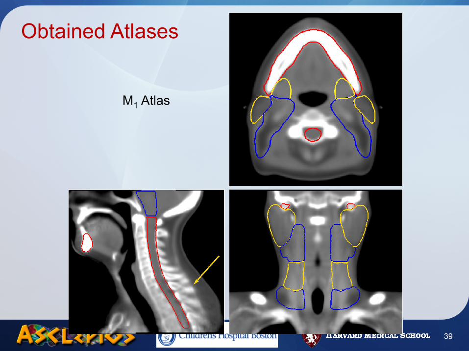
Obtained Atlases
M1 Atlas
39
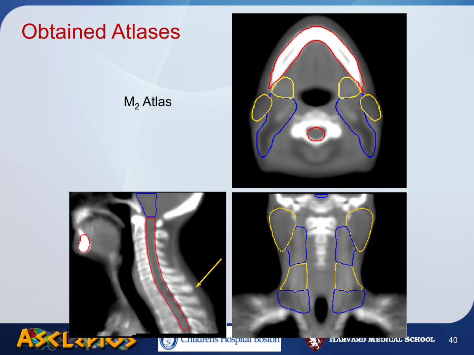
Obtained Atlases
M2 Atlas
40
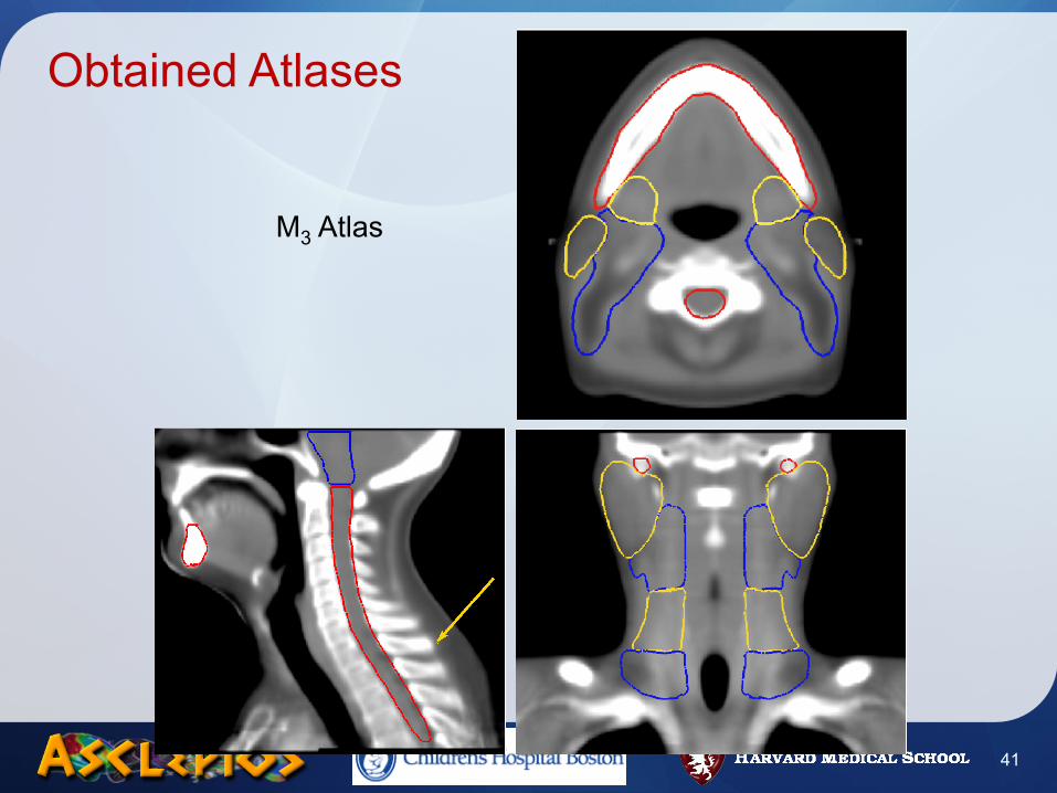
Obtained Atlases
M3 Atlas
41

Qualitative Results
Manual Segmentation
42

M1 Atlas Segmentation
Qualitative Results
43
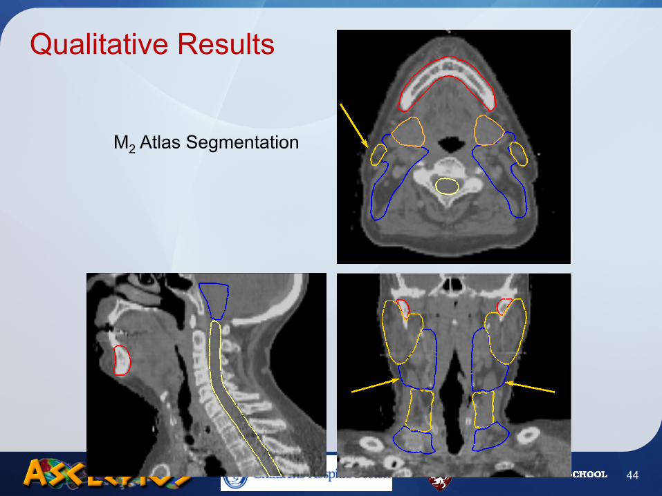
M2 Atlas Segmentation
Qualitative Results
44

M3 Atlas Segmentation
Qualitative Results
45
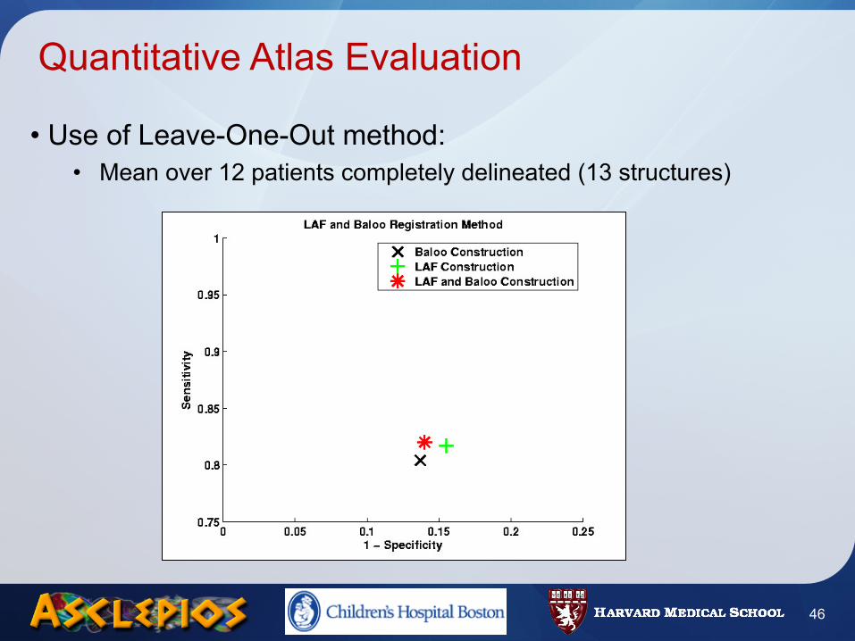
Quantitative Atlas Evaluation
• Use of Leave-One-Out method:• Mean over 12 patients completely delineated (13 structures)
46
Road Map
• Introduction• Methods
• Atlas Construction• Locally Affine Registration• Average Segmentations Construction
• Results• Registration validation• Head and Neck Atlas Construction
• Conclusion
47
Conclusion
• Original method to build an head and neck atlas• Symmetric atlas, unbiased• Typical structures computations from manual segmentations
• Locally affine registration: an adapted registration framework• Smooth transformation able to handle atlas/patient variability• Strong a priori constraint very robust
• Results• Fast segmentation of structures of interest• Precise segmentation not needing the clinician to set parameters
48
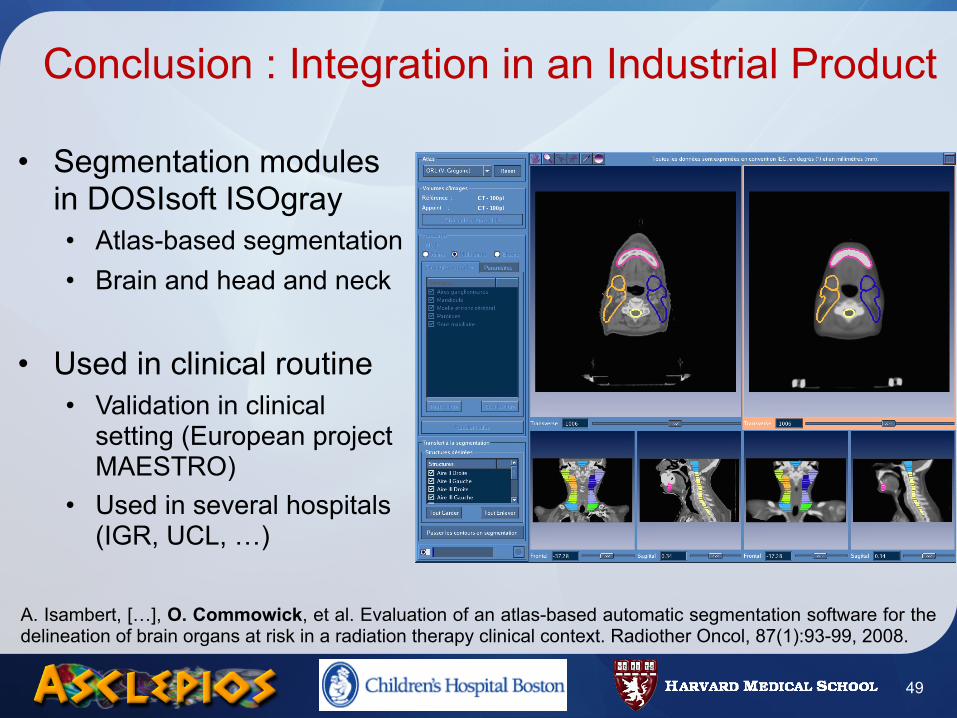
Conclusion : Integration in an Industrial Product
• Segmentation modules in DOSIsoft ISOgray• Atlas-based segmentation• Brain and head and neck
• Used in clinical routine• Validation in clinical
setting (European project MAESTRO)
• Used in several hospitals (IGR, UCL, …)
49
A. Isambert, […], O. Commowick, et al. Evaluation of an atlas-based automatic segmentation software for the delineation of brain organs at risk in a radiation therapy clinical context. Radiother Oncol, 87(1):93-99, 2008.

Perspectives
• Other representations for average segmentations• Statistical shape models
- Need to incorporate robustness- Handling multiple structures
• Kappa measure (Liliane Ramus, ISBI 2009, Boston)
• Atlas as a step of segmentation• Couple with very precise segmentation algorithms
- Graph cuts, level sets, …
• Going towards patient adapted atlases• Minimize errors due to anatomical variability
50
Contacts & Acknowledgments
• Contacts• [email protected]• http://olivier.commowick.org/
• CRL, Children’s Hospital Boston (http://www.crl.med.harvard.edu)• Simon K. Warfield
• INRIA Asclepios Team (http://www-sop.inria.fr/asclepios)• N. Ayache, X. Pennec, G. Malandain, V. Arsigny, P. Fillard, R. Stefanescu, O.
Clatz, L. Ramus …
• DOSIsoft S.A (http://www.dosisoft.com)• Clinicians
• P.Y. Bondiau (CAL, Nice), V. Grégoire (UCL, Bruxelles), A. Isambert (IGR, Villejuif)
51
52
Thank You


