PT1E-1040 Buzzer Unit TAN-5000 Series Operating Manual Request for the Customers • Read and understand this operating manual before using the buzzer unit. • Use the buzzer unit in accordance with the operating manual. • Regardless of warranty period, we shall not make any indemnification for accidents and damage caused by using this product. Make sure to read the warranty policy specified on the warranty. • Because this is a safety unit, a regular maintenance for every six months and daily maintenance must be performed. • If any abnormality is found in the buzzer unit, notify it to RIKEN KEIKI immediately. (Visit our Web site to find your nearest RIKEN KEIKI office.)
Transcript
PT1E-1040
Buzzer Unit
TAN-5000 Series Operating Manual
Request for the Customers • Read and understand this operating manual before using the buzzer unit. • Use the buzzer unit in accordance with the operating manual. • Regardless of warranty period, we shall not make any indemnification for accidents and
damage caused by using this product. Make sure to read the warranty policy specified on the warranty.
• Because this is a safety unit, a regular maintenance for every six months and daily maintenance must be performed.
• If any abnormality is found in the buzzer unit, notify it to RIKEN KEIKI immediately. (Visit our Web site to find your nearest RIKEN KEIKI office.)
TAN-5000 - 2 -
<Contents>
1 Outline of the Product.............................................................................................. 3 1-1. Preface .................................................................................................................... 3 1-2. Purpose of use ........................................................................................................ 3 1-3. Definition of DANGER, WARNING, CAUTION, and NOTE ..................................... 3 2 Important Notices on Safety .................................................................................... 4 2-1. Danger cases .......................................................................................................... 4 2-2. Warning cases......................................................................................................... 5 2-3. Precautions ............................................................................................................. 6 3 Product Components............................................................................................... 7 3-1. Main unit and accessories ....................................................................................... 7 3-2. Outline drawing ....................................................................................................... 8 3-3. Installation drawing.................................................................................................. 9 3-4. Names and functions for each part.......................................................................... 10 3-5. Detaching and attaching the buzzer unit ................................................................. 11 3-6. Block diagram.......................................................................................................... 12 4 How to Use.............................................................................................................. 13 4-1. Before using the buzzer unit.................................................................................... 13 4-2. Precautions for installation points ............................................................................ 13 4-3. Precautions for system designing............................................................................ 14 4-4. How to wire.............................................................................................................. 16 4-5. Grounding................................................................................................................ 21 5 How to Operate ....................................................................................................... 22 5-1. Preparation for start-up............................................................................................ 22 5-2. Basic operating procedures..................................................................................... 22 5-3. How to start the buzzer unit ..................................................................................... 23 5-4. Description of operation........................................................................................... 24 5-4-1. Common first and second alarm activation.............................................................. 24 5-4-2. Common fault alarm activation ................................................................................ 24 5-5. Description of operation........................................................................................... 27 5-5-1. How to change alarm contacts ................................................................................ 27 5-5-2. Maintenance mode.................................................................................................. 27 6 Measures for Abnormalities ..................................................................................... 28 7 Product Specifications ............................................................................................. 29 7-1. List of specifications ................................................................................................ 29
1 Outline of the Product 1-1. Preface
- 3 - TAN-5000
1
Outline of the Product
1-1. Preface Thank you for choosing our buzzer unit TAN-5000 series for use with the RM-5000 series. Please check that the model number of the product you purchased is included in the specifications on this manual. This manual explains how to use the buzzer unit and its specifications. It contains information required for using the buzzer unit properly. Not only the first-time users but also the users who have already used the product must read and understand the operating manual to enhance the knowledge and experience before using the buzzer unit. The buzzer unit must be used in combination with the RM-5000 series indicator/alarm unit. Be sure to read the operating manual of the indicator/alarm unit.
1-2. Purpose of use • The buzzer unit, when receiving an alarm signal from either of the multiple RM-5000 series
indicator/alarm units, sounds an alarm buzzer and activates the common first and second alarm contacts to inform of a danger.
Model Alarm activation
TAN-5000 Self-latching type TAN-5000L Lock-in type
• The buzzer unit, when receiving a fault alarm signal from either of the multiple RM-5000 series
indicator/alarm units, activates the common fault alarm contacts to inform of an abnormality to external circuits.
1-3. Definition of DANGER, WARNING, CAUTION, and NOTE
DANGER This message indicates that improper handling may cause serious damage on
life, health or assets.
WARNING This message indicates that improper handling may cause serious damage on health or assets.
CAUTION This message indicates that improper handling may cause minor damage on health or assets.
NOTE This message indicates advice on handling.
2 Important Notices on Safety 2-1. Danger cases
TAN-5000 - 4 -
2
Important Notices on Safety
2-1. Danger cases
DANGER This is not an explosion-proof unit. Do not operate the buzzer unit in a place where combustible gases or vapors are present. Operating the buzzer unit in such an environment will lead to extreme dangers.
2 Important Notices on Safety 2-2. Warning cases
- 5 - TAN-5000
WARNING • Indicator/alarm unit
Connect the buzzer unit only to the RM-5000 series indicator/alarm unit. Otherwise, the buzzer unit or equipment connected to it may be damaged.
• Power supply Before turning on the buzzer unit, always check that the power supply voltage is compliant with the specifications.
• Need of grounding circuit Do not cut the grounding circuit inside or outside the buzzer unit or disconnect the wire from the grounding terminal. In both of the cases, the buzzer unit will be in danger.
• Defects in protective functions
When seeming defects are found in the protective functions, such as protective grounding and fuses, do not start the buzzer unit.Before starting the buzzer unit, check the protective functions for defects.
• Fuse
To prevent fire, use a fuse with the specified ratings for the buzzer unit. Turn the power switch OFF and cut the mains power before replacing a fuse. Do not use an unspecified fuse or short-circuit the fuse holder. For more information on fuses, please contact RIKEN KEIKI.
• External connection
Before connecting the buzzer unit to external equipments or external control circuit, securely connect it to a protective grounding circuit.
• Response to a gas alarm
There are extreme dangers if a gas exceeding an alarm setpoint is detected. Take proper actions based on your judgment.
2-2. Warning cases
2 Important Notices on Safety 2-3. Precautions
TAN-5000 - 6 -
2-3. Precautions
CAUTION • Do not use a transceiver or mobile phone, etc. near the buzzer unit.
Radio wave from a transceiver near the buzzer unit or its cables may disturb operations. If a transceiver or other such device is used, it must be used in a place where it disturbs nothing.
• To restart the buzzer unit, you must wait five seconds or more before doing it. Restarting the buzzer unit in less than five seconds may cause errors.
• The safety and quality of the product cannot be guaranteed if this operating manual is ignored when operating or maintaining the buzzer unit or it is altered in any way or repaired using unspecified parts. We will not be liable for any accidents caused by these conditions.
• Careful consideration should be given to instrumentation to maintain safety even when a trouble
like disconnection of power/signal cable or unexpected malfunction or failure occurs. • This is an electrical appliance. Be careful that it may be affected, in rare cases, by power supply
noises, static electricity, and electromagnetic noises. Before using this product in an environment with such noises, provide for protective measures against them.
3 Product Components 3-1. Main unit and accessories
- 7 - TAN-5000
3
Product Components
3-1. Main unit and accessories
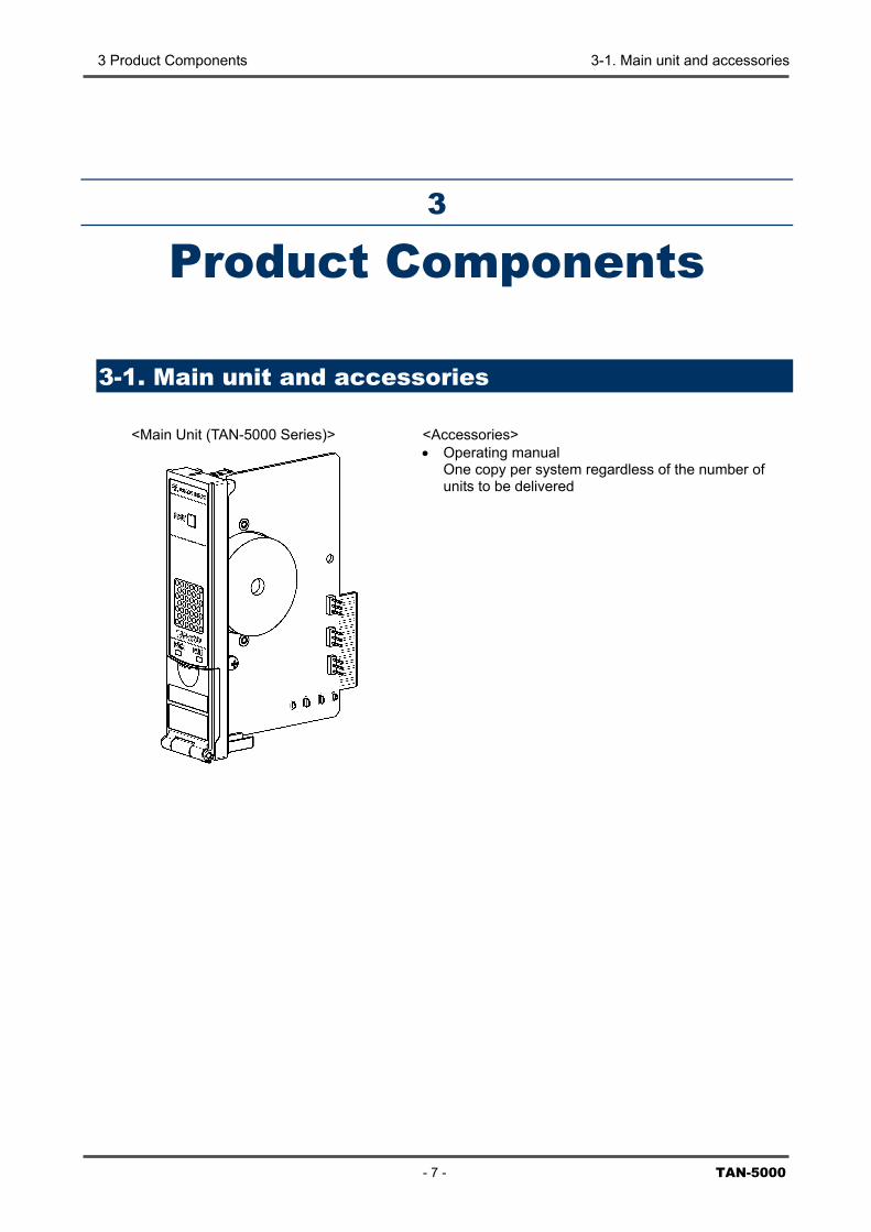
<Main Unit (TAN-5000 Series)>
<Accessories> • Operating manual
One copy per system regardless of the number of units to be delivered
3 Product Components 3-2. Outline drawing
TAN-5000
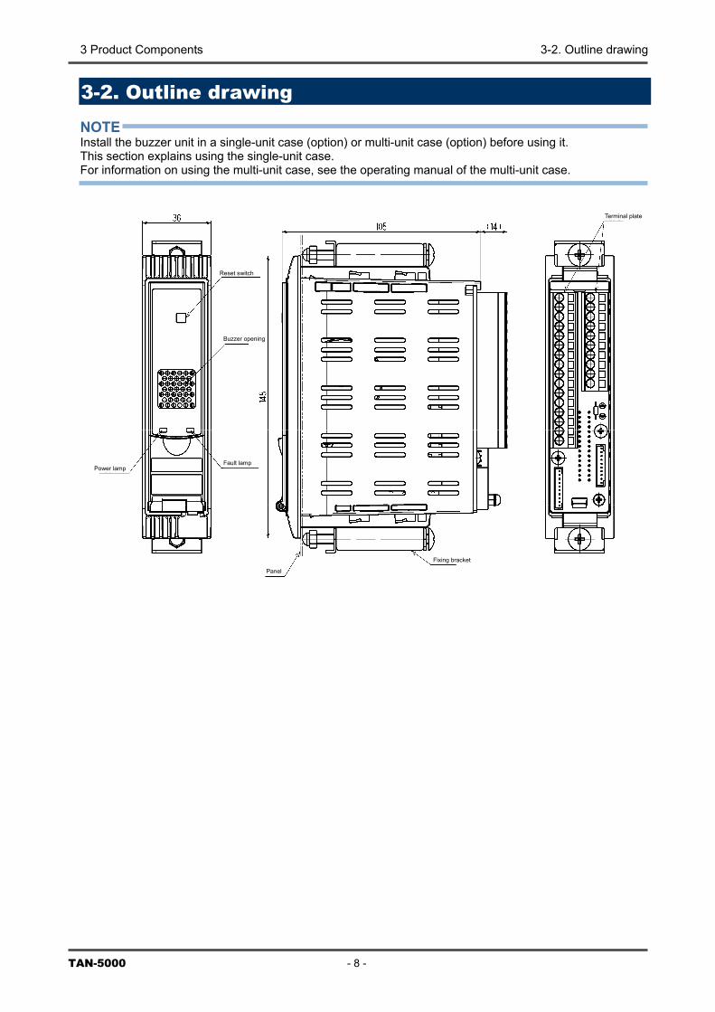
3-2. Outline drawing NOTE Install the buzzer unit in a single-unit case (option) or multi-unit case (option) before using it. This section explains using the single-unit case. For information on using the multi-unit case, see the operating manual of the multi-unit case.
h
Power lamp
Terminal plate
Reset switc
- 8 -
Buzzer opening
Fault lamp
Panel
Fixing bracket
3 Product Components 3-3. Installation drawing
- 9 -
3-3. Installation drawing NOTE Install the buzzer unit in a single-unit case (option) or multi-unit case (option) before using it. This section explains using the single-unit case. For information on using the multi-unit case, see the operating manual of the multi-unit case. <Panel Cut Dimensions> When installed in two rows vertically When installed in one row vertically and N columns horizontally
Single-point panel cut dimensions
Panel thickness
Buzzer unit + Indicator/alarm unit
Md
P
200
or m
ore
ulti-point panel cut imensions
s
anel thicknes
TAN-5000
3 Product Components 3-4. Names and functions for each part
TAN-5000 - 10 -
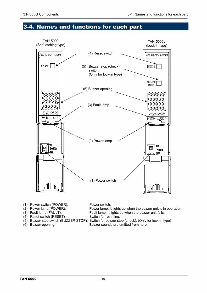
3-4. Names and functions for each part (1) Power switch (POWER): Power switch. (2) Power lamp (POWER): Power lamp. It lights up when the buzzer unit is in operation. (3) Fault lamp (FAULT): Fault lamp. It lights up when the buzzer unit fails. (4) Reset switch (RESET): Switch for resetting. (5) Buzzer stop switch (BUZZER STOP): Switch for buzzer stop (check). (Only for lock-in type) (6) Buzzer opening: Buzzer sounds are emitted from here.
(2) Power lamp
(3) Fault lamp
(1) Power switch
(4) Reset switch
(6) Buzzer opening
TAN-5000 (Self-latching type)
TAN-5000L (Lock-in type)
(5) Buzzer stop (check) switch (Only for lock-in type)
3 Product Components 3-5. Detaching and attaching the buzzer unit
- 11 - TAN-5000
3-5. Detaching and attaching the buzzer unit Detach or attach the buzzer unit from the single-unit case or multi-unit case according to the following procedure. (1) Attaching procedure
• Open the front cover of the buzzer unit. • Make sure that the power switch of the buzzer unit is OFF. • Insert the buzzer unit along the rail into the single-unit case or multi-unit case. • Push it in until an click is heard and you feel that it is locked in. • Gently pull it to make sure that the buzzer unit does not come off. • Close the front cover of the buzzer unit.
(2) Detaching procedure
• Open the front cover of the buzzer unit. • Make sure that the power switch of the buzzer unit is OFF. • While pressing the lock lever on the lower right of the buzzer unit, hold the front cover and pull it out
of the case. • Close the front cover of the buzzer unit.
Front cover Press the lock lever upward.
CAUTION Turn off the power of the buzzer unit before attaching or detaching it. Otherwise, a failure may be caused.
CAUTION This is a precision device. Be careful not to drop it when detaching it. Dropping the unit compromises its original performance or causes malfunctions.
3 Product Components 3-6. Block diagram
TAN
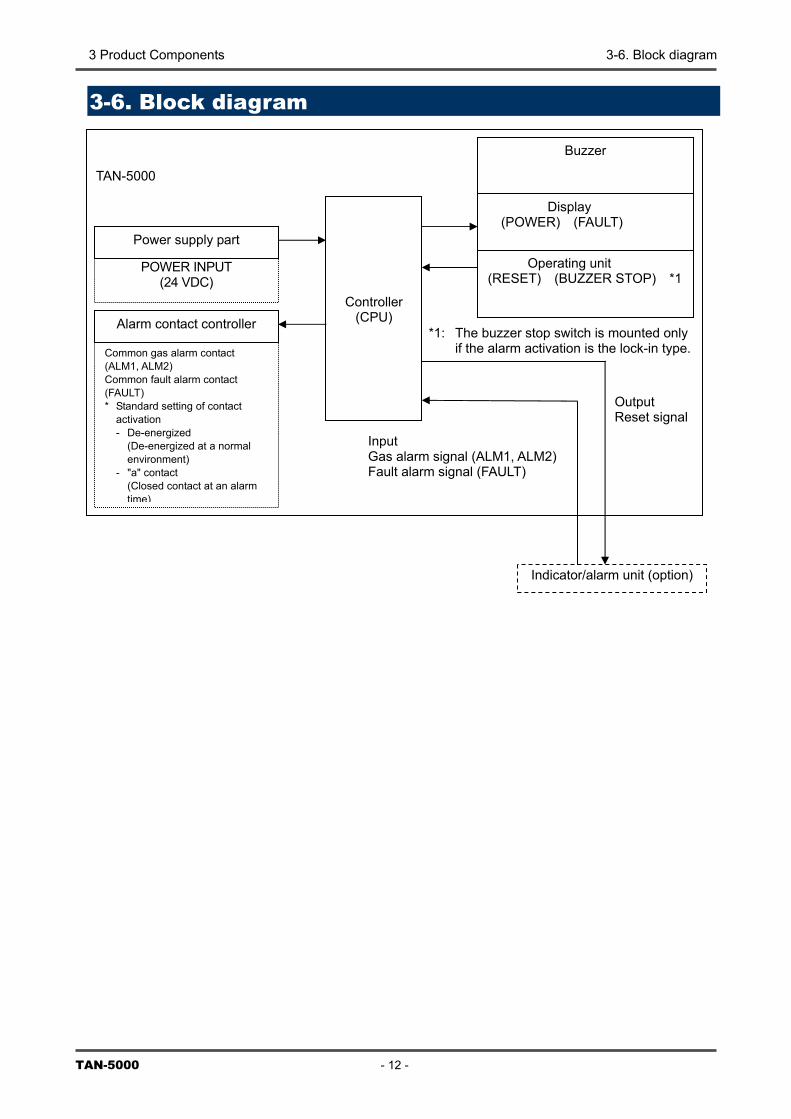
3-6. Block diagram
TAN-5000
Controller (CPU)
POWER INPUT (24 VDC)
Power supply part
Alarm contact controller
Output Reset signal
Input Gas alarm signal (ALM1, ALM2) Fault alarm signal (FAULT)
*1: The buzzer stop switch is mounted only if the alarm activation is the lock-in type.
Display (POWER) (FAULT)
Operating unit (RESET) (BUZZER STOP) *1
Buzzer
Common gas alarm contact (ALM1, ALM2) Common fault alarm contact (FAULT) * Standard setting of contact
activation - De-energized
(De-energized at a normal environment)
- "a" contact (Closed contact at an alarm time)
-5000 - 12 -
Indicator/alarm unit (option)
4 How to Use 4-1. Before using the buzzer unit
- 13 - TAN-5000
4
How to Use
4-1. Before using the buzzer unit Not only the first-time users but also the users who have already used the product must follow the operating precautions. Ignoring the precautions may damage the buzzer unit, resulting in inaccurate gas detection. NOTE Install the buzzer unit in a single-unit case (option) or multi-unit case (option) before using it. This section explains using the single-unit case. For information on using the multi-unit case, see the operating manual of the multi-unit case.
4-2. Precautions for installation points Do not install the buzzer unit in a place with vibrations or shocks. The buzzer unit consists of sensitive electronic parts. The buzzer unit must be installed in a stable place where it cannot drop and without vibrations or shocks. Do not install the buzzer unit in a place exposed to water, oil or chemicals. When selecting installation points, avoid a place where the buzzer unit is exposed to water, oil or chemicals. Do not install the buzzer unit in a place where the temperature drops below -10ºC or rises over 40ºC. The operating temperature of the buzzer unit is -10 to 40ºC. The buzzer unit must be installed in a stable place where the operating temperature is maintained and does not change suddenly. Do not install the buzzer unit in a place exposed to direct sunlight or sudden changes in the temperature. When you select installation sites, avoid a place where it is exposed to direct sunlight or radiant heat (infrared rays emitted from a high-temperature object), and where the temperature changes suddenly. Condensation may be formed inside the buzzer unit. Keep the buzzer unit (and its cables) away from noise source devices. When selecting installation points, avoid a place where high-frequency/high-voltage devices exist.
CAUTION This is a precision device. Because the buzzer unit may not provide the specified performance in some places (environments), check the environment in the installation point, and then take appropriate actions if necessary.
4 How to Use 4-3. Precautions for system designing
TAN-5000 - 14 -
Do not install the buzzer unit in a place where maintenance of the buzzer unit cannot be performed or where handling the buzzer unit involves dangers. Regular maintenance of the buzzer unit must be performed. Do not install the buzzer unit in a place where the machinery must be stopped when maintenance is performed in its inside, where parts of the machinery must be removed to perform maintenance, or where the buzzer unit cannot be removed because tubes or racks prevent access to it. Do not install the buzzer unit in a place where maintenance involves dangers, for example, near a high-voltage cable. Do not install the buzzer unit in machinery which is not properly grounded. Before installing the buzzer unit in machinery, the machinery must be grounded properly. Do not install the buzzer unit in a place where other gases exist around it. The buzzer unit must not be installed in a place where other gases exist around it.
4-3. Precautions for system designing Using a stable power supply The external output and alarm contact of the buzzer unit may be activated when the power is turned on, when momentary blackout occurs, or when the system is being stabilized. In such cases, use a UPS (uninterrupted power supply), or take appropriate actions on the receiving side. The buzzer unit must be provided with the following power supply.
Power supply voltage 24 VDC (21.6 – 26.4 VDC) (Terminal voltage of the buzzer unit)
Allowed time of momentary blackout
Up to 10 milliseconds (To recover from the momentary blackout for 10 milliseconds or more, restart the buzzer unit.)
Example of actions To ensure continuous operation and activation, install a protective power supply outside the buzzer unit.
Others Do not use it with a power supply of large power load or high-frequency noise.
Example of actions Use a line filter to avoid the noise source if necessary.
Heat radiation designing When it is installed in the closed instrumentation board, attach ventilation fans above and below the board.
CAUTION An unstable power supply and noise may cause malfunctions or false alarms. The descriptions in this section must be reflected on the designing of a system using the buzzer unit.
4 How to Use 4-3. Precautions for system designing
- 15 - TAN-5000
CAUTION The "b" contact (break contact) under de-energized state may be opened momentarily by a physical shock, such as external force. When the "b" contact is selected for the alarm contact, take appropriate actions to prepare for a momentary activation, for example, add signal delay operation (approximately one second) to the receiving side of the "b" contact.
Introducing protective measures against lightning If cables are installed outside the factory/plant, or if internal cables are installed in the same duct as the cables coming from outside the factory/plant, "lightning" will cause problems. Because lightning acts as a large emission source while cables act as a receiving antenna, devices connected to the cables may be damaged. Lightning cannot be prevented. Cables installed in a metal conduit or under the ground cannot be completely protected from inductive lightning surge caused by lightning. Although complete elimination of disasters caused by lightning is impossible, the following protective measures can be taken.
Protection against lightning
Take appropriate measures in accordance with the importance of the facilities and the environment. • Connect the transmission signal route by using optical fiber. • Provide protection by a lightning arrester (cable arrester).
(Although inductive lightning surge can be transmitted through the cable, it is prevented by installing a lightning arrester before the field devices and central processing equipment. For information on how to use a lightning arrester, please contact the manufacturer.)
Grounding In addition to lightning, there are more sources of surge noise. To protect units from these noise sources, the units must be grounded.
* The lightning arrester has a circuit to remove a surge voltage which damages field devices, so that
signals may be attenuated by installing the arrester. Before installing a lightning arrester, verify that it works properly.
Proper use of alarm contact The alarm contact of the buzzer unit is used to transmit signals to activate an external buzzer or alarm lamp. Do not use the buzzer unit for controlling purposes (e.g., controlling the shutdown valve). The specifications for the alarm contact of the buzzer unit are based on the resistant load conditions. If inductive load is used at the alarm contact, the following errors will occur easily because counter electromotive force is generated at the contact. • Deposition, defective insulation or defective contact at the relay contact • Damage of any electric parts due to high-voltage generated inside the buzzer unit • Abnormal operations by an out-of-control CPU
CAUTION • In principle, do not activate inductive load at the alarm contact of the buzzer unit. (In particular,
never use the inductive load to activate a fluorescent lamp or motor.) • If inductive load is activated, relay it with an external relay (contact amplification). However,
because the coil of an external relay also involves inductive load, select a relay at a lower voltage (100 VAC or below), and then protect the contact of the buzzer unit with an appropriate surge absorbing part, such as a CR circuit.
4 How to Use 4-4. How to wire
TAN-5000 - 16 -
If load is to be activated, appropriate measures must be taken to stabilize the operation of the buzzer unit and protect the alarm contact referring to the following information. • Relay it with an external relay at a lower voltage of 100 VAC or below (contact amplification). At the same
time, the surge absorbing part SK1 suitable for the specifications must be attached to the external relay. • In addition, the surge absorbing part SK2 must be attached to the loaded side of the external relay if
necessary. • It may be recommended that the surge absorbing part should be attached to the contact for certain load
conditions. It must be attached to an appropriate position by checking how the load is activated.
4-4. How to wire
TAN-5000
SK1 SK2
Coi
l
Load
Power supply
Power supply
External relay (low voltage relay)
Alarm contact
* SK1, SK2: Surge absorbing parts
CAUTION • When wiring, be careful not to apply stresses on the terminal plate when (overweight) cables are
installed. • The power cables and signal cables must not be installed together with the motor power cables,
etc. • When stranded wires are used, prevent wires from contacting each other. • Use the specified tools to wire.
4 How to Use 4-4. How to wire
<Figure of Terminal Plate> NOTE Install the buzzer unit in a single-unit case (option) or multi-unit case (option) before using it. This section explains using the single-unit case. For information on using the multi-unit case, see the operating manual of the multi-unit case.
*1: A signal to
by the use*2: Output on
RS-485 fu*3: Used for t
When this
Unassigned
Buzzer stop (check) Signal input (from outside)
R
U
BS
R(
C
F(
F(
B(
S(
U
Power input 24 VDC
T e
eset signal input from outside)
- 17 -
be used between the indicator/alarm unit (option) and the buzzer unit. This mayr. ly if RS-485 (option) is installed in the indicator/alarm unit.The buzzer unit does nnction. The input-output from the indicator alarm unit passes through the buzzer ransition wiring for signals between devices when single-unit cases (option) are c connector is used, no transition wiring between cases is required at the terminal
eset signal output(*3)
nassigned
uzzer stop (check) ignal output (*3)
ommon (*3)
irst alarm signal input *1, *3)
ault alarm signal input *1, *3)
uzzer signal input *1, *3)
econd alarm signal input *1, *3)
nassigned
RS-485 Input-output (*2, *3)
Common first alarm contact output
Common second alarm contact output
Common fault alarm contact output
Grounding terminal
Connector for between single-unit cases (*3)
erminal plat
TAN-5000
not be used
ot have the unit. onnected. plate.
4 How to Use 4-4. How to wire
TAN-5000 - 18 -
<Specifications of Terminal Plate> Specifications of terminal plate • Rated voltage: 250 VAC • Rated current: 12 A
Driver slot
Wire insertion hole D
river slot W
ire insertion hole
4 How to Use 4-4. How to wire
- 19 - TAN-5000
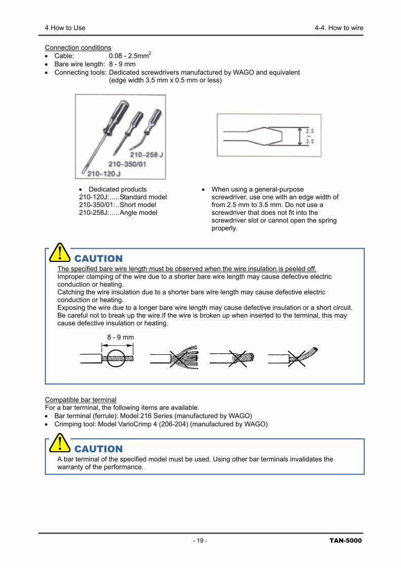
CAUTION The specified bare wire length must be observed when the wire insulation is peeled off. Improper clamping of the wire due to a shorter bare wire length may cause defective electric conduction or heating. Catching the wire insulation due to a shorter bare wire length may cause defective electric conduction or heating. Exposing the wire due to a longer bare wire length may cause defective insulation or a short circuit. Be careful not to break up the wire.If the wire is broken up when inserted to the terminal, this may cause defective insulation or heating.
Connection conditions • Cable: 0.08 - 2.5mm2 • Bare wire length: 8 - 9 mm • Connecting tools: Dedicated screwdrivers manufactured by WAGO and equivalent
(edge width 3.5 mm x 0.5 mm or less)
Compatible bar terminal For a bar terminal, the following items are available. • Bar terminal (ferrule): Model 216 Series (manufactured by WAGO) • Crimping tool: Model VarioCrimp 4 (206-204) (manufactured by WAGO)
• Dedicated products 210-120J:.....Standard model 210-350/01:..Short model 210-258J:.....Angle model
• When using a general-purpose screwdriver, use one with an edge width of from 2.5 mm to 3.5 mm. Do not use a screwdriver that does not fit into the screwdriver slot or cannot open the spring properly.
8 - 9 mm
CAUTION A bar terminal of the specified model must be used. Using other bar terminals invalidates the warranty of the performance.
4 How to Use 4-4. How to wire
TAN-5000 - 20 -
<How to Connect to Terminal Plate> When cables are connected to the terminal plate, use the dedicated screwdriver or a compatible flathead screwdriver to do it as shown below.
Wiring: Perform wiring as shown in the figure below.
Removal: In the same way as for the wiring procedure, insert the screwdriver to remove the wire.
CAUTION The right tools must be used. Only one wire can be connected to one wiring hole. When the wire is inserted into the driver slot by mistake, it does not contact the conductive part. This may cause defective electric conduction or heating. When the wire is inserted under the spring by mistake, it does not contact the conductive part. This may cause defective electric conduction or heating.
(4) Properly peel off a wire and insert it into the wiring hole (round hole). The wire will go in smoothly if you insert the wire along the edge of the round hole.
(5) When the wire is inserted as far as it will go, pull out the screwdriver while holding the wire.
(6) To check whether the wire is connected securely, pull the wire gently. (Do not pull the wire strongly.)
(1) Insert the screwdriver at an angle into the operating slot (square hole).
(2) While standing the screwdriver upright, insert it all the way securely.
(3) If you have done the previous steps properly, the screwdriver is kept upright when you let it go.
4 How to Use 4-5. Grounding
- 21 -
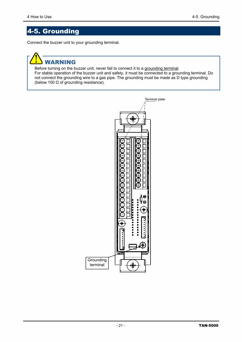
WARNING Before turning on the buzzer unit, never fail to connect it to a grounding terminal. For stable operation of the buzzer unit and safety, it must be connected to a grounding terminal. Do not connect the grounding wire to a gas pipe. The grounding must be made as D type grounding (below 100 Ω of grounding resistance).
4-5. Grounding Connect the buzzer unit to your grounding terminal.
Groundingterminal
T
TAN-5000
erminal plate
5 How to Operate 5-1. Preparation for start-up
TAN-5
5
How to Operate
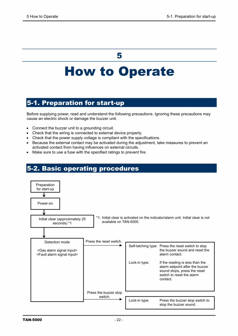
5-1. Preparation for start-up Before supplying power, read and understand the following precautions. Ignoring these precautions may cause an electric shock or damage the buzzer unit. • Connect the buzzer unit to a grounding circuit. • Check that the wiring is connected to external device properly. • Check that the power supply voltage is compliant with the specifications. • Because the external contact may be activated during the adjustment, take measures to prevent an
activated contact from having influences on external circuits. • Make sure to use a fuse with the specified ratings to prevent fire.
5-2. Basic operating procedures
Preparationfor start-up
000
Power-on
Initial clear (approximately 25 seconds) *1
Detection mode
<Gas alarm signal input> <Fault alarm signal input>
Self-latching type: Press the reset switch to stop the buzzer sound and reset the alarm contact.
Lock-in type: If the reading is less than the
alarm setpoint after the buzzer sound stops, press the reset switch to reset the alarm contact.
Press the reset switch.
*1: Initial clear is activated on the indicator/alarm unit. Initial clear is not available on TAN-5000.
Press the buzzer stop switch.
- 22 -
Lock-in type: Press the buzzer stop switch to stop the buzzer sound.
5 How to Operate 5-3. How to start the buzzer unit
- 23 - TAN-5000
5-3. How to start the buzzer unit • Before turning on the power switch, check that the buzzer unit is installed properly. • Open the front cover of the buzzer unit to find the power switch. • Turn ON the power switch. • The power lamp lights up and the operation is started.
OFF
ON
Slide Front cover
Power switch
5 How to Operate 5-4. Description of operation
TAN-5000 - 24 -
5-4. Description of operation
5-4-1. Common first and second alarm activation (1) Self-latching type
The indicator/alarm unit outputs a gas alarm signal when the reading exceeds each of the gas alarm setpoints. The buzzer unit, when receiving this signal, sounds the buzzer and activates the common first and second alarm contacts. The buzzer and the common first and second alarm contacts are the self-latching type. Press the reset switch to stop the buzzer sound and reset the common first and second alarm contacts.
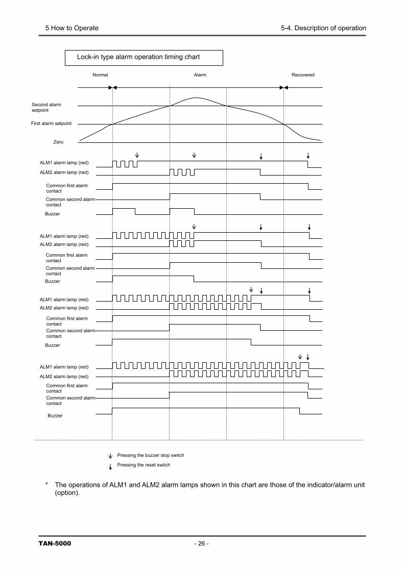
(2) Lock-in type
The indicator/alarm unit, outputs a gas alarm signal when the reading exceeds each of the gas alarm setpoints. The buzzer unit, when receiving this signal, sounds the buzzer and activates the common first and second alarm contacts. The buzzer and the common first and second alarm contacts are the self-latching type. Press the buzzer stop switch to stop the buzzer sound. The reset switch is effective if the reading is less than the alarm setpoint after the buzzer stop switch is pressed. It resets the common first and second alarm contacts.
5-4-2. Common fault alarm activation The indicator/alarm unit outputs a fault alarm signal when the self-diagnostic function discovers a fault. The buzzer unit, when receiving this signal, activates the common fault alarm contact <<Auto-Reset>>. The common fault alarm contact is automatically reset after the system recovers from the fault status.
NOTE The buzzer does not sound when a fault alarm is triggered <<Standard Setting>>. To enable sounding of the buzzer when a fault alarm is triggered, please contact RIKEN KEIKI.
5 How to Operate 5-4. Description of operation
Self-latching type alarm operation timing chart 1
Recovered Alarm Normal
ALM1 alarm lamp (red)
ALM2 alarm lamp (red)
Common first alarm contact Common second alarm contact Buzzer
ALM1 alarm lamp (red)
Zero point
First alarm setpoint
Second alarm setpoint
ALM2 alarm lamp (red)
A
AL
A
A
Common first alarmcontact
*
Common second a ntact
L
M
L
C
L
larm coBuzzer
M1 alarm lamp (red)
2 alarm lamp (red)
M1 alarm lamp (red)
ommon second ntact
M2 alarm lamp (red)
Common first alarmcontact
Common second alarm
contact
alarm coBuzzer
Common first alarmcontact
- 25 - TAN-5000
The operations of ALM1 and ALM2 alarm lamps shown in this chart are those of the indicator/alarm unit (option).
Pressing the reset switch
Buzzer
5 How to Operate 5-4. Description of operation
TA
*
Lock-in type alarm operation timing chart
Recovered Alarm Normal
Zero
First alarm setpoint
Second alarm setpoint
ALM1 alarm lamp (red)
Cc
B
ALM2 alarm lamp (red)
ALM
CcCcB
ALM
ALM
B
ALM
ALM
ALM
Common first alarmcontact
ommon second alarm ontact
uzzer
1 alarm lamp (red)
ommon first alarm ontact ommon second alarm ontact
2 alarm lamp (red)
uzzer
1 alarm lamp (red)
Common first alarm contact Common second alarm contact
uzzer
2 alarm lamp (red)
1 alarm lamp (red)
2 alarm lamp (red)
Common first alarmcontact
Common second alarm contact
N-5000 - 26 -
The operations of ALM1 and ALM2 alarm lamps shown in this chart are those of the indicator/alarm unit (option).
Buzzer
Pressing the buzzer stop switch
Pressing the reset switch
5 How to Operate 5-5. Description of operation
- 27 - TAN-5000
5-5. Description of operation
5-5-1. How to change alarm contacts There are two types of alarm contacts: (1) Common first and second alarm contacts for gas alarm signals from the indicator/alarm unit and (2) Common fault alarm contacts for fault alarm signals. To change the settings of the contact specifications (such as the "a" or "b" contact), please contact RIKEN KEIKI.
5-5-2. Maintenance mode If the gas concentration reading exceeds the alarm setpoint of the indicator/alarm unit during the adjustment or calibration of the detector head, the buzzer unit sounds the buzzer and activates the first or second alarm contact. Use the maintenance mode to disable these operations. Entering the maintenance mode • Keep the reset switch pressed. • The power switch starts blinking <<Maintenance Mode>>. Exiting the maintenance mode • Keep the reset switch pressed. • The power switch remains lit <<Detection Mode>>.
WARNING • When the buzzer unit enters the maintenance mode from the detection mode while an alarm is
activated, the alarm contact is released. • After the adjustment is completed, do not forget to keep the reset switch pressed and return to
the detection mode. If the buzzer unit remains in the maintenance mode, it automatically returns to the detection mode in ten hours.
6 Measures for Abnormalities 5-5. Description of operation
TAN-5000 - 28 -
6
Measures for Abnormalities The power lamp (green lamp) is off. • Fuse open-circuit <Causes and Actions> • The cause can be either a failure of the buzzer unit or a failure of the external power supply. Find out the
cause, take appropriate action, and then replace the fuse with a specified spare part.
7 Product Specifications 7-1. List of specifications
- 29 - TAN-5000
7
Product Specifications
7-1. List of specifications [TAN-5000]
Power display POWER lamp on or blinking (green) Gas alarm display Buzzer Gas alarm pattern Self-latching Gas alarm contact No-voltage contact 1a or 1b (2 step independent)
De-energized (energized at an alarm) or energized (de-energized at an alarm) Fault alarm/self diagnosis
System abnormalities, indicator/alarm unit common fault alarm
Fault alarm display FAULT lamp on (yellow) with or without buzzer sounds Fault alarm pattern Auto-reset Fault alarm contact No-voltage contact 1a or 1b
De-energized (energized at an alarm) or energized (de-energized at an alarm) Contact capacity 100 VAC - 0.5A/30 VDC - 1.5A (resistant load) Power supply 24 VDC (21.6 – 26.4 VDC) Power consumption Maximum 2 W Operating temperatures
-10 - 40 (at a constant condition)
Operating humidities 10 to 90%RH (Non-condensing) Structure Card type with front display used enclosed in a case (a single-unit or multi-unit
case) External dimensions Approx. 29.6 (W) x 120 (H) x 92 (D) mm (projection portions excluded) Weight Approx. 80g
* Specifications subject to changes without notice.
7 Product Specifications 7-1. List of specifications
TAN-5000 - 30 -
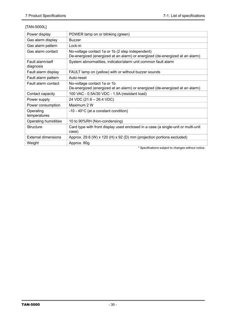
[TAN-5000L]
Power display POWER lamp on or blinking (green) Gas alarm display Buzzer Gas alarm pattern Lock-in Gas alarm contact No-voltage contact 1a or 1b (2 step independent)
De-energized (energized at an alarm) or energized (de-energized at an alarm) Fault alarm/self diagnosis
System abnormalities, indicator/alarm unit common fault alarm
Fault alarm display FAULT lamp on (yellow) with or without buzzer sounds Fault alarm pattern Auto-reset Fault alarm contact No-voltage contact 1a or 1b
De-energized (energized at an alarm) or energized (de-energized at an alarm) Contact capacity 100 VAC - 0.5A/30 VDC - 1.5A (resistant load) Power supply 24 VDC (21.6 – 26.4 VDC) Power consumption Maximum 2 W Operating temperatures
-10 - 40°C (at a constant condition)
Operating humidities 10 to 90%RH (Non-condensing) Structure Card type with front display used enclosed in a case (a single-unit or multi-unit
case) External dimensions Approx. 29.6 (W) x 120 (H) x 92 (D) mm (projection portions excluded) Weight Approx. 80g
* Specifications subject to changes without notice.
- 31 - TAN-5000
Warranty Policy RIKEN KEIKI CO., LTD., warrants gas alarm equipment sold by us to be free from defects in materials, workmanship, and performance for a period of one year from date of shipment from RIKEN KEIKI CO., LTD., Inc. Any parts found defective within that period will be repaired or replaced, at our option, free of charge. This warranty does not apply to those items which by their nature are subject to deterioration or consumption in normal service, and which must be cleaned, repaired, or replaced on a routine basis. Warranty is voided by abuse including mechanical damage, alteration, rough handling, or repair procedures not in accordance with the operator’s manual. This warranty indicates the full extent of our liability, and we are not responsible for removal or replacement costs, local repair costs, transportation costs, or contingent expenses incurred without our prior approval.
THIS WARRANTY IS EXPRESSLY IN LIEU OF ANY AND ALL OTHER WARRANTIES AND REPRESENTATIONS, EXPRESSED OR IMPLIED, AND ALL OTHER OBLIGATIONS OR LIABILITIES ON THE PART OF RIKEN KEIKI CO., LTD., INCLUDING BUT NOT LIMITED TO, THE WARRANTY OF MERCHANTABILITY OR FITNESS FOR A PARTICULAR PURPOSE. IN NO EVENT SHALL RIKEN KEIKI CO., LTD., BE LIABLE FOR INDIRECT, INCIDENTAL, OR CONSEQUENTIAL LOSS OR DAMAGE OF ANY KIND CONNECTED WITH THE USE OF ITS PRODUCTS OR FAILURE OF ITS PRODUCTS TO FUNCTION OR OPERATE PROPERLY.
This warranty covers instruments and parts sold to users by authorized distributors, dealers, and representatives as appointed by RIKEN KEIKI CO., LTD. We do not assume indemnification for any accident or damage caused by the operation of this gas monitor, and our warranty is limited to the replacement of parts or our complete goods.