Page 1
Vishay Electronic GmbH
Hofmark-Aich-Str.36
D-84030 Landshut
Telefon +49 871 86-0
www.vishay.com
Document number: 13173 - Rev. 02
_________________________________________________________________________________________________________
QUALITY MANAGEMENT
Certified by VDE according to
DIN EN ISO 9001
Reg. No. 2556/QM/03.94
Capacitor protection relay
ESTAsym MD
Operating instructions
Page 2
ESTAsym MD Doc.No.: 13173 - Rev. 02 Operating instructions Page 2 of 50
Revision history
Date Name Revision Change
25.08.11 drt 00 initial document release
20.12.11 brm 01 update of content
07.05.12 fez 02 corrections
Page 3
ESTAsym MD Doc.No.: 13173 - Rev. 02 Operating instructions Page 3 of 50
Content
1 Characteristics ......................................................................................................................................... 4
2 Description of function ............................................................................................................................. 4
2.1 Capacitor Unbalance Protection ......................................................................................................... 4
2.2 Line Current Unbalance Protection ..................................................................................................... 4
2.3 Overvoltage Protection ........................................................................................................................ 4
2.4 Overheating Protection ....................................................................................................................... 5
2.5 Ground Fault Protection ...................................................................................................................... 5
2.6 Fundamental Harmonic Overcurrent Protection ................................................................................. 5
2.7 RMS – overcurrent Protection ............................................................................................................. 5
2.8 Undercurrent Protection ...................................................................................................................... 5
2.9 Capacitor Bank Discharge Timer ........................................................................................................ 6
3 Matching of protective function ................................................................................................................ 7
4 Block diagram ESTAsym MD .................................................................................................................. 8
5 Current inputs .......................................................................................................................................... 9
6 Optron inputs ........................................................................................................................................... 9
7 LCD display ........................................................................................................................................... 10
8 Keypad .................................................................................................................................................. 10
9 Relay outputs ......................................................................................................................................... 10
10 LED indicators ....................................................................................................................................... 10
11 Boot– Loader Software update .............................................................................................................. 13
12 Settings .................................................................................................................................................. 20
12.1 Example of parameter setting ESTAsym MD ................................................................................ 22
12.2 Setting parameter through PC screen ........................................................................................... 23
13 Display menu ......................................................................................................................................... 30
14 Technical data ....................................................................................................................................... 45
15 Immunity tests ....................................................................................................................................... 46
16 Dimensions and cut-out details ............................................................................................................. 48
17 Times of warning and tripping for the overheating protection ............................................................... 49
18 Times of tripping for Overvoltage protection ......................................................................................... 49
Page 4
ESTAsym MD Doc.No.: 13173 - Rev. 02 Operating instructions Page 4 of 50
1 Characteristics
The microprocessor-based capacitor protection relay ESTAsym MD is a versatile integrated current
measuring multi-function relay design, to be used for the protection of medium and high voltage capacitor
banks. Through the use of FFT techniques the ESTAsym MD extracts from measured line and unbalance
currents the currents of fundamental frequency and harmonics currents. From this results are calculated the
values used for the individual protective functions.
The capacitor protection relay can be used especially in capacitor banks connected in double wye and H
configuration. Protective functions provided by the ESTAsym MD are the following:
- Capacitor unbalance protection
- Line current unbalance protection
- Overvoltage protection
- Overheating protection
- Ground fault protection
- Fundamental harmonic and RMS - overcurrent protection
- Undercurrent protection
- Capacitor bank discharge timer
2 Description of function
2.1 Capacitor Unbalance Protection
The protection measures fundamental frequency of the natural unbalance current of capacitor bank and
compensates it for both amplitude and phase to zero, to enable detection of further changes, in both
amplitude and phase angel. Phase current input IL1 is used as synchronizing input for the compensation. The
phase angel indicates the leg in which the change in capacitance has occurred. The indication of failed leg
depends of the fact whether the capacitors have element fuses or not (Fig. 6 and 7).
The protection has two-stages, warning and tripping, both with adjustable definite timer. A trip signal is
output if associated threshold is exceeded for the definite time set. ESTAsym MD compares the stored
unbalance value with present phase-current.
2.2 Line Current Unbalance Protection
The protection calculates the fundamental frequency line current unbalance due to faults or failures within
the capacitor bank. The line current unbalance is calculated from 3-phase line currents. The protection
includes two-stages, warning and tripping, both with adjustable definite timer. A trip signal is output if value of
the line unbalance current exceeds the selected set point value for the definite time.
2.3 Overvoltage Protection
Page 5
ESTAsym MD Doc.No.: 13173 - Rev. 02 Operating instructions Page 5 of 50
The purpose of the overvoltage protection is to protect the capacitor bank against overload due to
fundamental and harmonics currents, which may lead to dielectric breakdown, i.e. short-circuit in a capacitor
element. The capacitor bank voltage is calculated from 3-phase line fundamental frequency component
current and from harmonic currents. Overvoltage factor is calculated and continuously compared with a
variable threshold. It is possible to choose between definite time characteristic and an inverse time
characteristic according to ANSI–curve. A trip signal is output if the set point value is exceeded for the
definite time.
2.4 Overheating Protection
Overheating protection stage is intended to be used for protection of serial reactance coils used within
capacitor banks. This protection is based on measuring the RMS 3-phase line currents and comparing them
with an adjustable threshold. The protection has either two stages, warning and tripping, both with adjustable
definite-time delay, or it is possible to select tripping time depending on the ratio of the actual current to the
nominal current. Warning time is half of tripping time. If the current exceeds the relevant set point value for
the definite-time delay, tripping or warning signal is output. The protection has two ANSI modes and tripping
time adjusting.
2.5 Ground Fault Protection
The protection calculates the fundamental frequency ground fault current, as the value of the vector sum of
the 3-phase line currents. The protection has two-stages, warning and tripping, both with adjustable definite
time. A trip signal is output if amplitude of the ground fault current exceeds the selected set point value for
the definite time.
2.6 Fundamental Harmonic Overcurrent Protection
The protection stage is measuring the fundamental frequency of 3-phase currents and comparing them with
an adjustable threshold. This function may be used for short circuit protection. A trip signal is output if the
value of the line current exceeds the selected set point value for the definite time. The protection has two
adjustable threshold values, each with separately adjustable time delay.
2.7 RMS – overcurrent Protection
The protection calculates RMS value of 3-phase currents and comparing them with an adjustable threshold.
The protection has two adjustable threshold values, each with separately adjustable time delay.
2.8 Undercurrent Protection
Page 6
ESTAsym MD Doc.No.: 13173 - Rev. 02 Operating instructions Page 6 of 50
The undercurrent protection is intended for the detection of capacitor bank disconnection. In case of voltage
loss in the feeding bus, the capacitor bank has to be disconnected from the system to prevent reapplication
of the voltage on the capacitors before they are fully discharged. The stage starts when one of the three
phase currents falls below the set level. If the undercurrent condition persists for a time longer than the set
operating time, the trip signal is output. The auxiliary contact of circuit breaker signals to ESTAsym MD if the
circuit breaker is off or a black-out occurred. The blocking-relay contact operates together with the tripping
contact. The closure time of blocking relay is given by the preset blocking time.
2.9 Capacitor Bank Discharge Timer
The relay includes an adjustable timer, started by the circuit breaker auxiliary contacts, which blocks the
breaker reclosing until the capacitor bank is discharged to an acceptable voltage level for switching in.
ESTAsym MD has an auxiliary contact for this purpose. It is possible to adjust the timer from 2s to 10 min
step 1s.
Page 7
ESTAsym MD Doc.No.: 13173 - Rev. 02 Operating instructions Page 7 of 50
3 Matching of protective function
Block or release of protection functions: By clicking the fields Enabled in the parameterization program it is
possible to enable or disable individual protection functions.
Matching of protective function
Connection of capacitor bank Protective function
Double wye with reactors Capacitor unbalance protection
Line current unbalance protection
Overvoltage protection
Overheating protection
Ground fault protection
Fundamental harmonic overcurrent protection
RMS - overcurrent protection
Undercurrent protection
Capacitor bank discharge timer
Double wye without reactors Capacitor unbalance protection
Line current unbalance protection
Overvoltage protection
Ground fault protection
Fundamental harmonic overcurrent protection
RMS - overcurrent protection
Undercurrent protection
Capacitor bank discharge timer
H3- Bridge with and without reactors Capacitor unbalance protection
Capacitor bank discharge timer
H1- Bridge with reactors Capacitor unbalance protection
Overvoltage protection
Overheating protection
Fundamental harmonic overcurrent protection
RMS - overcurrent protection
Undercurrent protection
Capacitor bank discharge timer
H1- Bridge without reactors Capacitor unbalance protection
Overvoltage protection
Fundamental harmonic overcurrent protection
RMS - overcurrent protection
Undercurrent protection
Capacitor bank discharge timer
Triple double wye Capacitor unbalance protection
Capacitor bank discharge timer
Page 8
ESTAsym MD Doc.No.: 13173 - Rev. 02 Operating instructions Page 8 of 50
Display
Power
Alarm
Trip
Error
µµµµC
RS 485
RxD DSR
TxD
DTR
GND
RS 232
Esc
Keypad
~
0
1 A (5 A)
2
3
5
6
8
9
11
51
52
50
31
32
33
34
35
36
37
38
39 40
41
42
43
44
45
Relay 1
Relay 2
Relay 3
Relay 4
Relay 5
POWER
12
INPUT CURRENT
13
14
15
16
17
18 19
20
21 22
23
24 25
26
27 28
29
30
INPUT CURRENT
INPUT CURRENT
INPUT CURRENT
0
0
0
N(-)
L(+)
P
Relay 6
OPT 1
OPT 2
OPT 3
OPT 4
( - )
B
A
PC in / output
1 A (5 A)
1 A (5 A)
1 A (5 A)
4 Block diagram ESTAsym MD
Fig.1 Block diagram ESTAsym MD
Page 9
ESTAsym MD Doc.No.: 13173 - Rev. 02 Operating instructions Page 9 of 50
5 Current inputs
Four current inputs are provided within ESTAsym MD. Each can be parameterized to 1A or 5A.
Matching of inputs
Connection of capacitor bank Inputs
Double wye Input 1 – Line current L1
Input 2 – Line current L2
Input 3 – Line current L3
Input 4 – Unbalance current
H- Bridge; Triple double wye Input 1 – Line current L1
Input 2 – Unbalance current 1
Input 3 – Unbalance current 2
Input 4 – Unbalance current 3
For phase currents, the current transformer ratio can be set to 10-3000/1A or /5A. The device evaluates
phase currents up to 6000A. The transforming ratio for unbalance current can be set to 1-100/1A or /5A.
6 Optron inputs
The OPT 1 and OPT 2 are used for Capacitor Bank Discharge Timer. This function is started by the circuit
breaker auxiliary contact wired to one of Optron inputs. OPT 3 and 4 are reserve. Input voltage can be in the
range from 20 to 220 V DC.
Circuit breaker
31 32
33 34 38
ESTAsym MD
OPT2
( - )
OPT1
=
+
Fig.2 Wiring of optocouplers
OFF
ON
Page 10
ESTAsym MD Doc.No.: 13173 - Rev. 02 Operating instructions Page 10 of 50
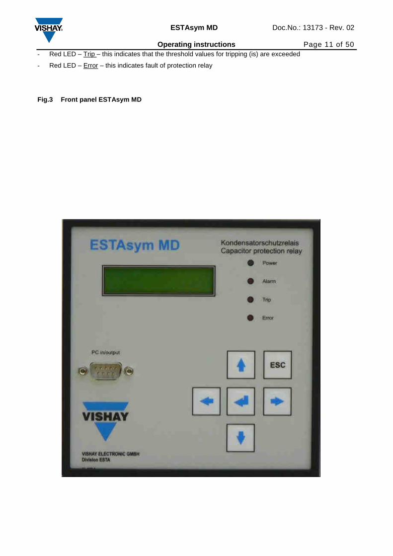
7 LCD display
Two lines, 16 character and full alpha-numeric LCD display (Fig.3) is provided on the front panel for the
following purposes:
- During normal relay operation:
Display of various measured parameters together with the threshold and times associated with these
parameters
- During relay configuration:
Interactive configuration of protection relay
- After warning or tripping:
Recording of fault currents and voltages at the instant of warning or tripping
8 Keypad
A six button key-pad is provided on the front panel (Fig.3) of relay for the following purposes:
- Interactive configuration of the protection relay
- Acknowledgement and resetting of trip conditions
9 Relay outputs
ESTAsym MD has six relay outputs:
- Relay 1, 2, 3, 4 and 6: optional protection function
- Relay 5 is self-monitoringsupervision relay
The user may program the relays to be manual or self-resetting, and to be normally energized or de-energized during the power-up healthy condition. All output relays have a full change – over contact. All N/O and N/C contact are permanently wired to the terminal block.
10 LED indicators
Four LED indicators are provided on the front panel (Fig.3) of relay, as follow:
- Green LED – Power ON /Healthy, this indicates that the auxiliary power supply is on
- Red LED – Warning, this indicates that the threshold values for warning (is) are exceeded
Page 11
ESTAsym MD Doc.No.: 13173 - Rev. 02 Operating instructions Page 11 of 50
- Red LED – Trip – this indicates that the threshold values for tripping (is) are exceeded
- Red LED – Error – this indicates fault of protection relay
Fig.3 Front panel ESTAsym MD
Page 12
ESTAsym MD Doc.No.: 13173 - Rev. 02 Operating instructions Page 12 of 50
Fig.4 Rear panel
Page 13
ESTAsym MD Doc.No.: 13173 - Rev. 02 Operating instructions Page 13 of 50
11 Boot– Loader Software update
Boot–Loader is means for updating ESTAsym MD software using RS232 interface. This function is provided
only by the producer.
Page 14
ESTAsym MD Doc.No.: 13173 - Rev. 02 Operating instructions Page 14 of 50
12 Settings Parameter setting ESTA sym MD
Protection Parameter Setting range
Capacitor unbalance Warning threshold
Tripping threshold
Lower threshold Iu
Lower threshold IL1
Iu 0,1 -100A Delay 0,1 - 6 s
Iu 0,1 -100A Delay 0,1 - 6 s
Iu 0,01 – 1 A
in A, (5% - 30%)IL1
Line current unbalance Warning threshold
Tripping threshold
Nominal current
1 - 30% In Delay 0,3 – 6s
2 - 30% In Delay 0,3 – 6s
In 10 - 3000A
Overvoltage IEC(ANSI):
Overvoltage factor
Phase capacitance
Nominal voltage (Line to Line)
Set time:
Overvoltage factor
Nominal voltage (Line to Line)
0,8; 0,9; 1,0; 1,10; 1,25; 1,50
1 - 6400 µF
2 - 450 kV
0,8 – 2,0
Delay 0,1 - 6 s
2 - 450 kV
Overheating Warning threshold
Tripping threshold
10 - 6000 A
10 - 6000 A
Set time on:
Delay warning 1 - 7200 s
Delay tripping 1 - 7200 s
Set time off:
The time sink with the ratio actual
current/nominal current.
Warning time is always a half of
tripping time
Ground fault Warning threshold
Tripping threshold
Nominal current
1 - 30% In Delay 0,3 – 6 s
1 - 30% In Delay 0,3 – 6 s
In 10 – 3000 A
Fundamental harmonic
overcurrent protection
RMS – overcurrent protection
Tripping threshold
Tripping threshold
10 – 6000 A Delay 0,1 - 6 s
10 – 6000 A Delay 0,3 - 6 s
Undercurrent Tripping threshold 10 – 3000 A Delay 0,3 - 6 s
Capacitor bank discharge timer Delay from 2s to 10min step 1s
Page 15
ESTAsym MD Doc.No.: 13173 - Rev. 02 Operating instructions Page 15 of 50
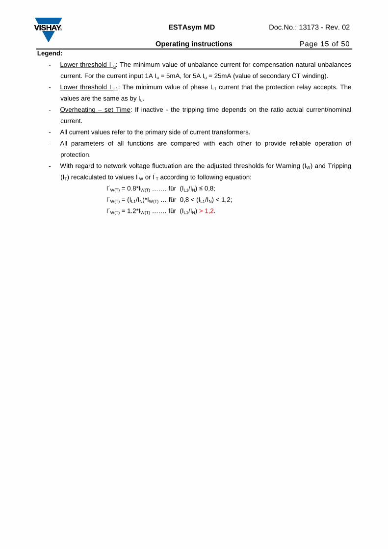
Legend:
- Lower threshold I u: The minimum value of unbalance current for compensation natural unbalances
current. For the current input 1A Iu = 5mA, for 5A Iu = 25mA (value of secondary CT winding).
- Lower threshold I L1: The minimum value of phase L1 current that the protection relay accepts. The
values are the same as by Iu.
- Overheating – set Time: If inactive - the tripping time depends on the ratio actual current/nominal
current.
- All current values refer to the primary side of current transformers.
- All parameters of all functions are compared with each other to provide reliable operation of
protection.
- With regard to network voltage fluctuation are the adjusted thresholds for Warning (IW) and Tripping
(IT) recalculated to values I´W or I´T according to following equation:
I´W(T) = 0.8*IW(T) ….… für (IL1/IN) ≤ 0,8;
I´W(T) = (IL1/IN)*IW(T) … für 0,8 < (IL1/IN) < 1,2;
I´W(T) = 1.2*IW(T) ….… für (IL1/IN) > 1,2.
Page 16
ESTAsym MD Doc.No.: 13173 - Rev. 02 Operating instructions Page 16 of 50
Fig. 5a Capacitor bank in H-Bridge with failure
Phase angel
φunb Faulty capacitor unit
0° C La or CLd
180° C Lc or CLb
Phase angel
φunb Faulty capacitor unit
0° C Lc or CLb
180° C La or CLd
1.) Failed element in the capacitor unit with element fuses
2.) Failed element in the capacitor unit without element fuses
CLc
CLb
CLd
CLa
ESTA Sym MD
L K
2(l) 3(k)
φun
ESTA Sym MD
L K
11(l) 12(k)
Page 17
ESTAsym MD Doc.No.: 13173 - Rev. 02 Operating instructions Page 17 of 50
Fig. 5b Capacitor bank in 3H-Bridge with failure
Phase angel
φunb Faulty capacitor unit
0° C L1a or CL1d
60° C L3c or CL3b
120° C L2a or CL2d
180° C L1c or CL1b
240° C L3a or CL3d
300° C L2c or CL2b
Phase angel
φunb Faulty capacitor unit
0° C L1c or CL1b 60° C L3a or CL3d 120° C L2c or CL2b 180° C L1a or CL1d 240° C L3c or CL3b 300° C L2a or CL2d
1.) Failed element in the capacitor unit with element fuses
2.) Failed element in the capacitor unit without element fuses
L1
ESTA Sym MD
L K
2(l) 3(k)
φunCL1c
CL1b
CL1d
CL1a
ESTA Sym MD
L K
5(l) 6(k)
L2
CL2c
CL2b
CL2d
CL2a
φun
ESTA Sym MD
L K
8(l) 9(k)
L3
CL3c
CL3b
CL3d
CL3a
φun
ESTA Sym MD
L K
11(l) 12(k)
Page 18
ESTAsym MD Doc.No.: 13173 - Rev. 02 Operating instructions Page 18 of 50
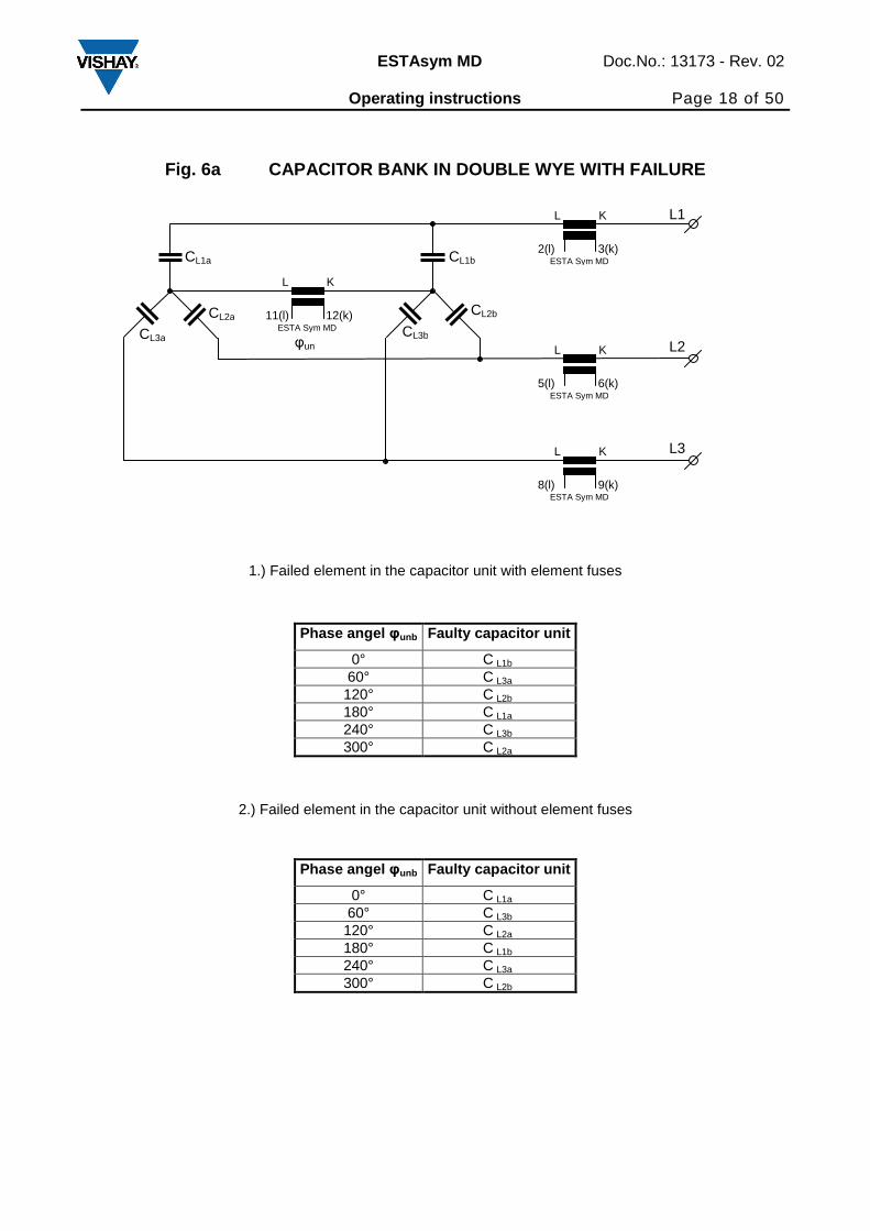
Fig. 6a CAPACITOR BANK IN DOUBLE WYE WITH FAILURE
Phase angel φunb Faulty capacitor unit
0° C L1b
60° C L3a 120° C L2b 180° C L1a 240° C L3b 300° C L2a
Phase angel φunb Faulty capacitor unit
0° C L1a
60° C L3b 120° C L2a 180° C L1b 240° C L3a 300° C L2b
2.) Failed element in the capacitor unit without element fuses
1.) Failed element in the capacitor unit with element fuses
CL1a
CL3a
CL2a
CL1b
CL3b
CL2b
L3
ESTA Sym MD
L K
8(l) 9(k)
L2
ESTA Sym MD
L K
5(l) 6(k)
L1
ESTA Sym MD
L K
2(l) 3(k)
φun
ESTA Sym MD
L K
11(l) 12(k)
Page 19
ESTAsym MD Doc.No.: 13173 - Rev. 02 Operating instructions Page 19 of 50
Fig. 6b CAPACITOR BANK IN TRIPLE DOUBLE WYE WITH F AILURE
L1
ESTA Sym MD
L K
2(l) 3(k)
L3
L2 φun
ESTA Sym MD
L K
5(l) 6(k)
CL1a
CL3a
CL2a
CL1b
CL3b
CL2b
φun
ESTA Sym MD
L K
8(l) 9(k)
CL1a
CL3a
CL2a
CL1b
CL3b
CL2b
φun
ESTA Sym MD
L K
11(l) 12(k)
CL1b
CL3b
CL2b
CL1a
CL3a
CL2a
Page 20
ESTAsym MD Doc.No.: 13173 - Rev. 02 Operating instructions Page 20 of 50
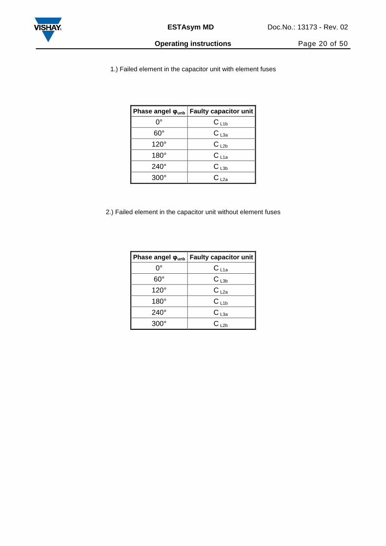
Phase angel φunb Faulty capacitor unit
0° C L1b
60° C L3a
120° C L2b
180° C L1a
240° C L3b
300° C L2a
Phase angel φunb Faulty capacitor unit
0° C L1a
60° C L3b
120° C L2a
180° C L1b
240° C L3a
300° C L2b
1.) Failed element in the capacitor unit with element fuses
2.) Failed element in the capacitor unit without element fuses
Page 21
ESTAsym MD Doc.No.: 13173 - Rev. 02 Operating instructions Page 21 of 50
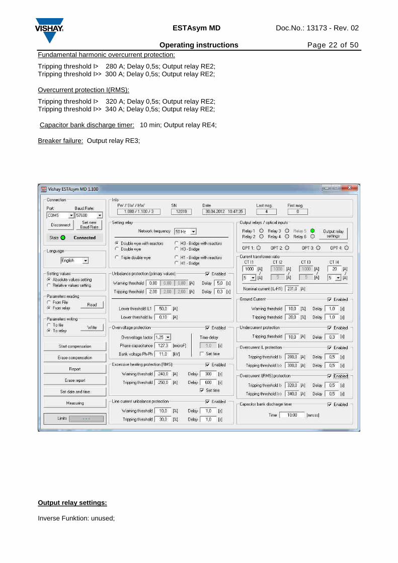
12.1 Example of parameter setting ESTAsym MD
Parametrs of capacitor bank: Capacitor Bank 4 MVAr, double wye Nominal line to line voltage Un =11 kV Nominal line current In = 231 A Phase capacity Cn = 127,3 µF Unit nominal voltage Un = 6,35 kV, (Line to line voltage 11 kV) Unit capacity Cn = 31,8µF Double wye with reactors ESTAsym MD settings: Double wye with reactors Nominal current 231 A Network frequency 50Hz Current transformer ratio: IL1 1000/5; Iu 20/5
Unbalance protection:
Warning threshold 0,8A; Delay 5s; Output relay RE1; Tripping threshold 2A, Delay 0,3s; Output relay RE2; Lower threshold IL1 50A Lower threshold Iu 0,1 mA
Overvoltage protection:
Overvoltage factor: 1,25 Phase capacitance: 127,3 µF Line to line Voltage: 11 kV (If set time and delay are empty, will be used ANSI-curve according to the paragraph 17) Tripping: Output relay RE2;
Excessive heating protection:
Warning threshold 240 A, Delay 300s; Output relay RE1; Tripping threshold 50 A, Delay 600s; Output relay RE2; (If set time and delay are empty, will be used ANSI-curve according to the paragraph 18)
Line current unbalance protection:
Warning threshold 10%; Delay 1s; Output relay RE1; Tripping threshold 30%; Delay 1s; Output relay RE2;
Ground current:
Warning threshold 10 %, Delay 1s; Output relay RE1; Tripping threshold 20 %, Delay 1s; Output relay RE2;
Undercurrent protection:
Tripping threshold 10 A, Delay 0,3s; Output relay RE2;
Page 22
ESTAsym MD Doc.No.: 13173 - Rev. 02 Operating instructions Page 22 of 50
Fundamental harmonic overcurrent protection:
Tripping threshold I> 280 A; Delay 0,5s; Output relay RE2; Tripping threshold I>> 300 A; Delay 0,5s; Output relay RE2;
Overcurrent protection I(RMS):
Tripping threshold I> 320 A; Delay 0,5s; Output relay RE2; Tripping threshold I>> 340 A; Delay 0,5s; Output relay RE2;
Capacitor bank discharge timer: 10 min; Output relay RE4;
Breaker failure: Output relay RE3;
Output relay settings:
Inverse Funktion: unused;
Page 23
ESTAsym MD Doc.No.: 13173 - Rev. 02 Operating instructions Page 23 of 50
RE1: Mode - ACK;
RE2: Mode - Auto;
RE3: Mode - End;
RE4: Mode - Auto;
RE5: for internal failure only;
RE6: Mode - ACK;
12.2 Setting parameter through PC screen
Connection:
- Ports – COM 1 – COM 8 are on the front or rear panel
- Connect - connect or disconnect the connection to relay
Page 24
ESTAsym MD Doc.No.: 13173 - Rev. 02 Operating instructions Page 24 of 50
- Select Baudrate
Language:
- Select language
Parameter reading:
- From file
- From relay
Parameter writing:
- To file
- To relay
Start compensation: Starting of natural current compensation
Erase compensation: Erase the compensation value
Report: Display of recorded data
Erase report: Erase recorded data
Set date and time: Setting date and time from PC to relay (internal time of the computer is sent to the
protection relay)
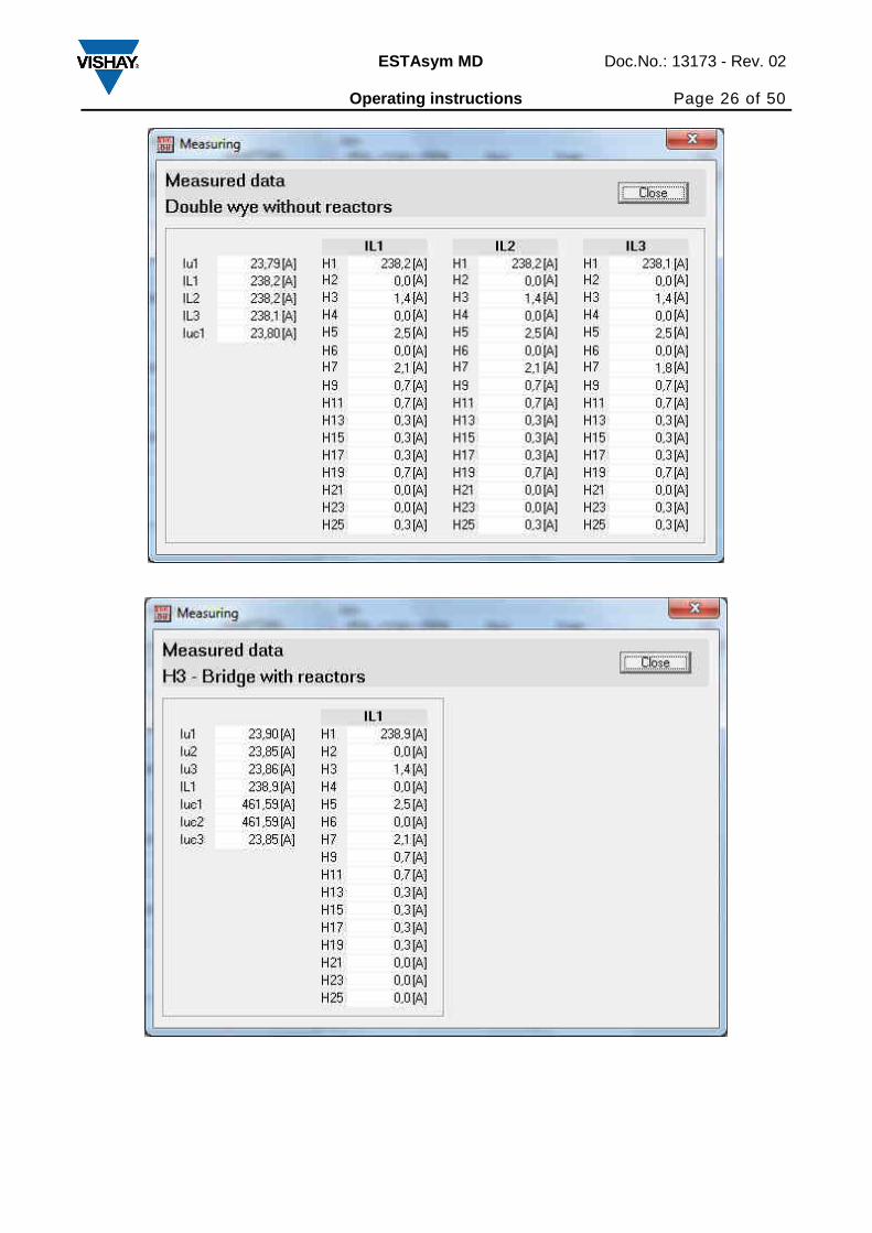
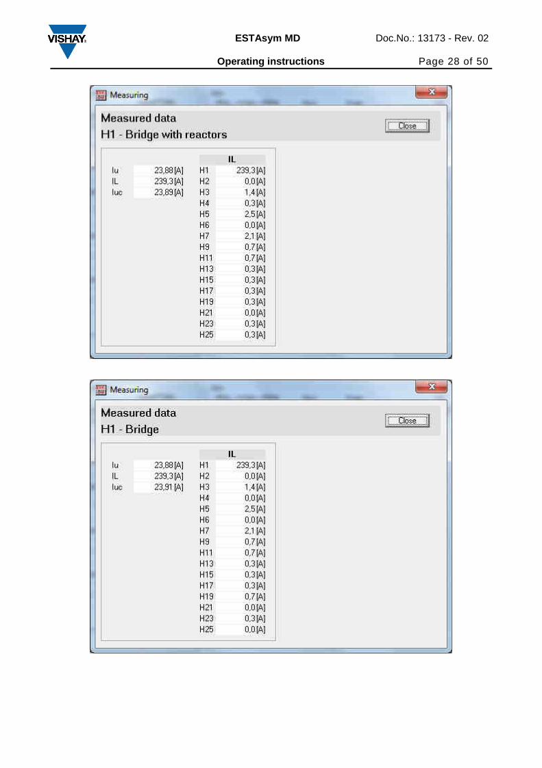
Measuring: Display of measured data
Info: Service data, program version, communication etc.
Setting relay: Setting network frequency, alarm acknowledgement (automatic, manual) and connection of
capacitor bank.
Output relays:
Each relay can be individually set to one of following modes:
• Acknowledgement – output contact is closed until the Acknowledgement button is pressed
• Automatic 1 s – output contact is closed for 1 second
• Automatic – output contact is closed while the condition is met
Optical inputs: Display of optical inputs states
Block or release of protection functions: By clicking the fields Enabled it is possible to enable or disable
individual protection functions.
Unbalance protection: Setting parameter of unbalance protection
Lower threshold IL1 is the minimum value of current IL1
Lower threshold Iu is the minimum value of current Iu
Overvoltage protection: Setting parameter of Overvoltage protection
IEC(ANSI):
Overvoltage factor
Phase capacitance
Ph/Ph-Voltage (Line to line voltage)
Set time:
Delay
Ph/Ph-Voltage (Line to line voltage)
Capacitor bank discharge timer: Set time
Current transformer ratio: Set the secondary current of current transformers x/1A or x/5 A.
Setting output relays: Setting the output relays, normally energized or de-energized during the power-up
Page 25
ESTAsym MD Doc.No.: 13173 - Rev. 02 Operating instructions Page 25 of 50
healthy condition.
Setting parameters of followed protection:
Line current unbalance protection
Ground current protection
Overcurrent protection
Undercurrent protection
Excessive heating protection: Set time on:
Setting parameters and delay
Set time off:
Setting parameters
Delay depend of ratio actual current/ nominal current
Measured data
Measured data on PC screen
Page 26
ESTAsym MD Doc.No.: 13173 - Rev. 02 Operating instructions Page 26 of 50
Page 27
ESTAsym MD Doc.No.: 13173 - Rev. 02 Operating instructions Page 27 of 50
Page 28
ESTAsym MD Doc.No.: 13173 - Rev. 02 Operating instructions Page 28 of 50
Page 29
ESTAsym MD Doc.No.: 13173 - Rev. 02 Operating instructions Page 29 of 50
Report
Example of Report
On LCD display is possible to display only data of the last event.
Measured data on LCD display:
Iu1; Iu2; Iu3
IL1; IL2; IL3
The data are displayed in dependence on connection of capacitor bank.
Legend:
Iu1;Iu2;Iu3 Unbalance currents
IL1; IL2; IL3 Line currents
Page 30
ESTAsym MD Doc.No.: 13173 - Rev. 02 Operating instructions Page 30 of 50
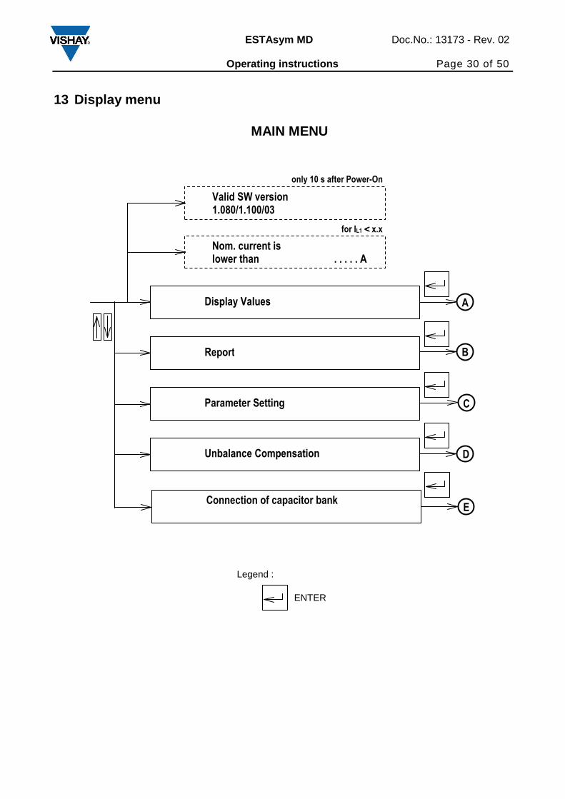
13 Display menu
MAIN MENU
ENTER
Legend :
Nom. current is lower than . . . . . A
Display Values
Report
Parameter Setting
D
C
B
A
Unbalance Compensation
for IL1 <<<< x.x
Connection of capacitor bank E
Valid SW version 1.080/1.100/03
only 10 s after Power-On
Page 31
ESTAsym MD Doc.No.: 13173 - Rev. 02 Operating instructions Page 31 of 50
DISPLAY VALUES DOUBLE WYE (WITH REACTORS)
H – BRIDGE (WITH REACTORS), TRIPLE DOUBLE WYE
Line 1
Current A
Line 2
Current A
Line 3
Current A
Unbalance
Current A
A
Line 1
Current A
Unbalance
Current 1 A
Unbalance
Current 2 A
Unbalance
Current 3 A
A
Page 32
ESTAsym MD Doc.No.: 13173 - Rev. 02 Operating instructions Page 32 of 50
(= Event)
(only for Unbalance Protection)
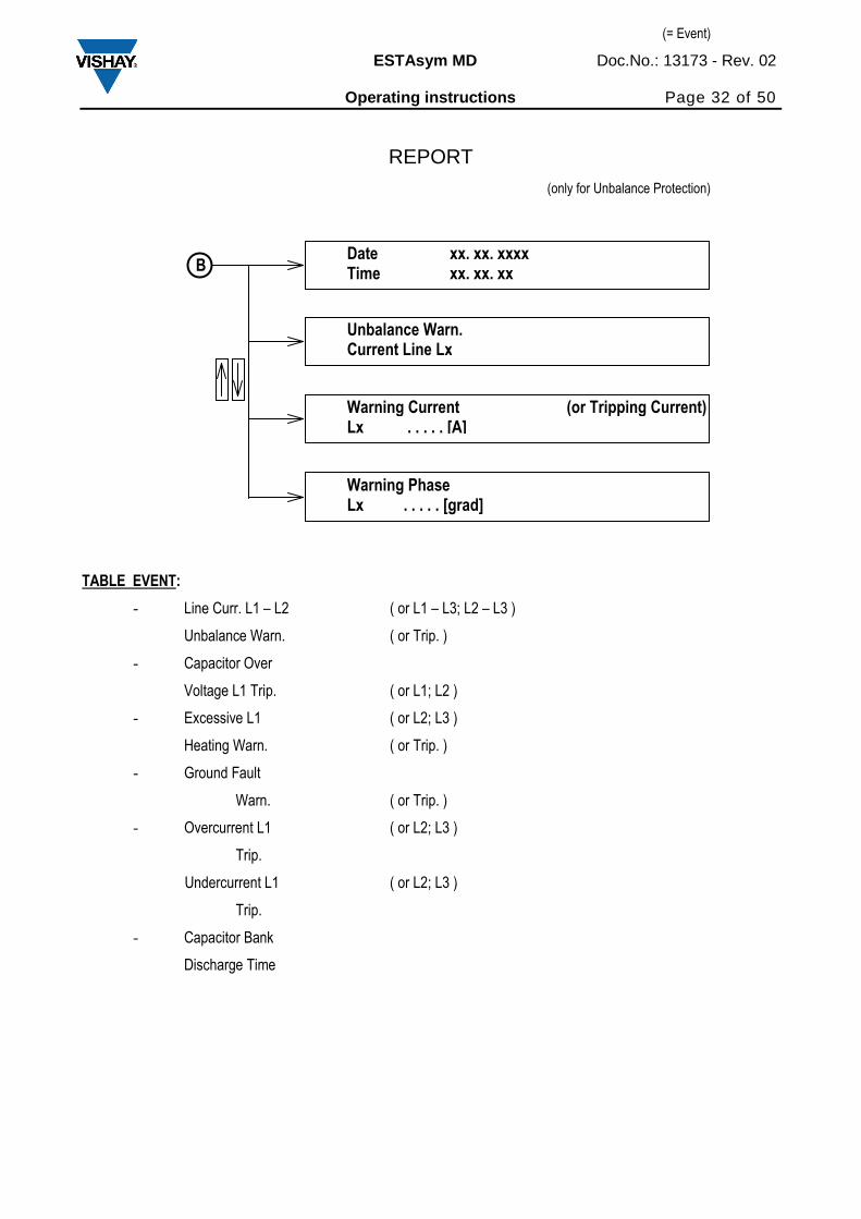
REPORT
TABLE EVENT:
- Line Curr. L1 – L2 ( or L1 – L3; L2 – L3 )
Unbalance Warn. ( or Trip. )
- Capacitor Over
Voltage L1 Trip. ( or L1; L2 )
- Excessive L1 ( or L2; L3 )
Heating Warn. ( or Trip. )
- Ground Fault
Warn. ( or Trip. )
- Overcurrent L1 ( or L2; L3 )
Trip.
Undercurrent L1 ( or L2; L3 )
Trip.
- Capacitor Bank
Discharge Time
Date xx. xx. xxxx Time xx. xx. xx
Unbalance Warn. Current Line Lx
Warning Current (or Tripping Current) Lx . . . . . [A]
Warning Phase Lx . . . . . [grad]
B
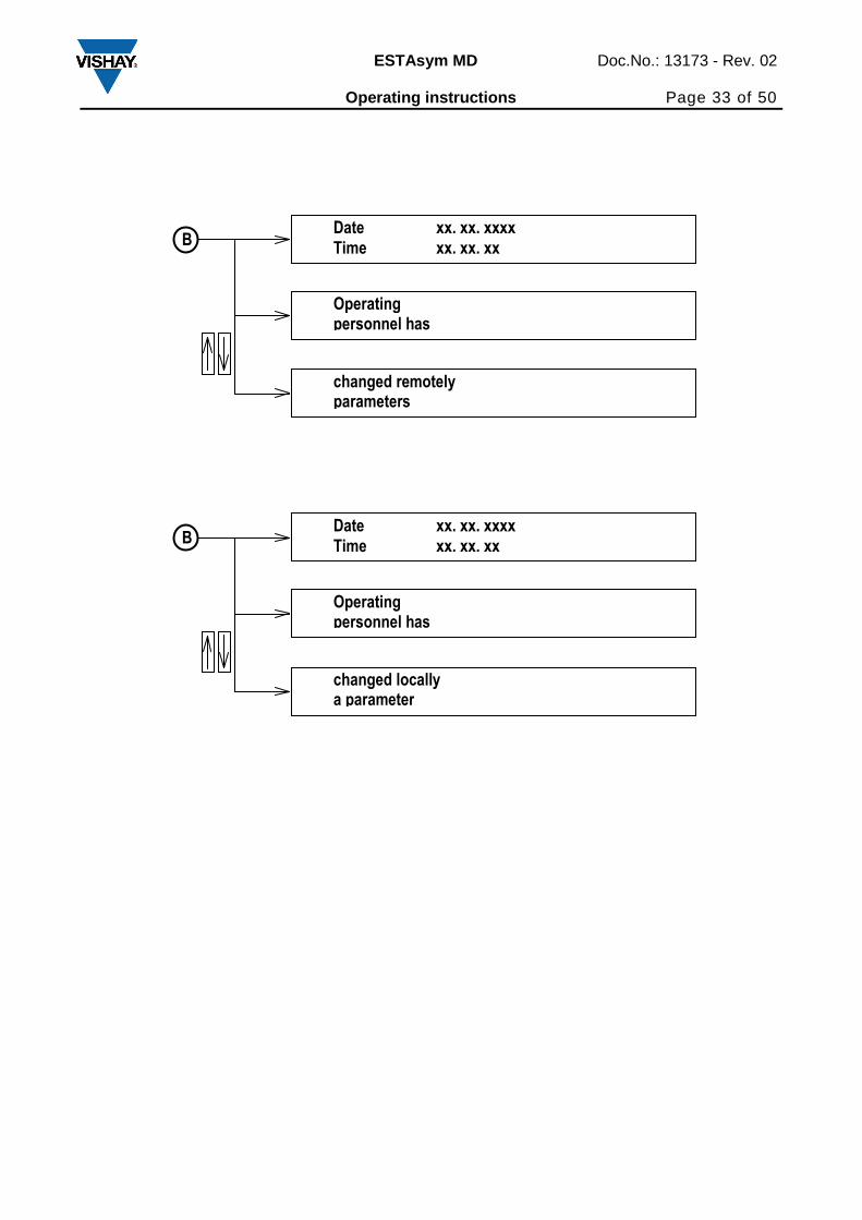
Page 33
ESTAsym MD Doc.No.: 13173 - Rev. 02 Operating instructions Page 33 of 50
Date xx. xx. xxxx Time xx. xx. xx
Operating personnel has
changed remotely parameters
B
Date xx. xx. xxxx Time xx. xx. xx
Operating personnel has
changed locally a parameter
B
Page 34
ESTAsym MD Doc.No.: 13173 - Rev. 02 Operating instructions Page 34 of 50
ENTER
Legend :
PARAMETER SETTING DOUBLE WYE WITH REACTORS
Unbalance Protection
Line Current Unbalance Prot.
C C1
Overvoltage Protection
C2
Overvolt Ratio x.xx ( or ANSI x.xx)
Change enable
Change
Overvolt Protect Time x.x [ s]
Excessive Heat. Protection
Ground Fault Protection
Overcurrent Protection
Capacitor Bank Discharge Timer
Undercurrent Protection
C3
C4
C7
Inhibit Time xx:xx [mm:ss]
C5
Change enable
Change
Overcurrent Protection >>
Overcurrent Protection >
C5
Overcurrent RMS Protection
C6
Overcurrent RMS Protection >>
Overcurrent RMS Protection >
C6
(only for set Time)
Page 35
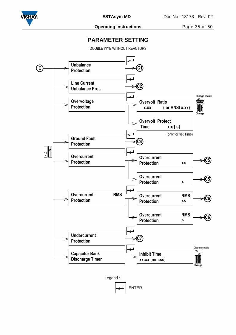
ESTAsym MD Doc.No.: 13173 - Rev. 02 Operating instructions Page 35 of 50
PARAMETER SETTING DOUBLE WYE WITHOUT REACTORS
ENTER
Legend :
Unbalance Protection
Line Current Unbalance Prot.
C C1
Overvoltage Protection
C2
Overvolt Ratio x.xx ( or ANSI x.xx)
Change enable
Change
Overvolt Protect Time x.x [ s]
Ground Fault Protection
Overcurrent Protection
Capacitor Bank Discharge Timer
Undercurrent Protection
C4
C7
Inhibit Time xx:xx [mm:ss]
C5
Change enable
Change
Overcurrent Protection >>
Overcurrent Protection >
C5
Overcurrent RMS Protection
C6
Overcurrent RMS Protection >>
Overcurrent RMS Protection >
C6
(only for set Time)
Page 36
ESTAsym MD Doc.No.: 13173 - Rev. 02 Operating instructions Page 36 of 50
PARAMETER SETTING
H- BRIDGE H1 WITH OR WITHOUT REACTORS
ENTER
Legend :
Unbalance Protection
C C1
Capacitor Bank Discharge Timer
Change enable
Change
Inhibit Time xx:xx [mm:ss]
Page 37
ESTAsym MD Doc.No.: 13173 - Rev. 02 Operating instructions Page 37 of 50
ENTER
Legend :
PARAMETER SETTING H- BRIDGE H1 WITH REACTORS
Unbalance Protection
C C1
Overvoltage Protection
Overvolt Ratio x.xx ( or ANSI x.xx)
Change enable
Change
Overvolt Protect Time x.x [ s]
Excessive Heat. Protection
Overcurrent Protection
Capacitor Bank Discharge Timer
Undercurrent Protection
C3
C7
Inhibit Time xx:xx [mm:ss]
C5
Change enable
Change
Overcurrent Protection >>
Overcurrent Protection >
C5
Overcurrent RMS Protection
C6
Overcurrent RMS Protection >>
Overcurrent RMS Protection >
C6
(only for set Time)
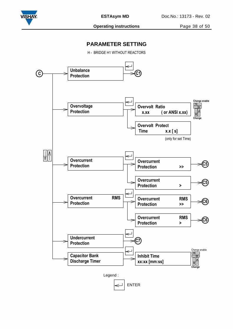
Page 38
ESTAsym MD Doc.No.: 13173 - Rev. 02 Operating instructions Page 38 of 50
ENTER
Legend :
PARAMETER SETTING H - BRIDGE H1 WITHOUT REACTORS
Unbalance Protection
C C1
Overvoltage Protection
Overvolt Ratio x.xx ( or ANSI x.xx)
Change enable
Change
Overvolt Protect Time x.x [ s]
Overcurrent Protection
Capacitor Bank Discharge Timer
Undercurrent Protection
C7
Inhibit Time xx:xx [mm:ss]
C5
Change enable
Change
Overcurrent Protection >>
Overcurrent Protection >
C5
Overcurrent RMS Protection
C6
Overcurrent RMS Protection >>
Overcurrent RMS Protection >
C6
(only for set Time)
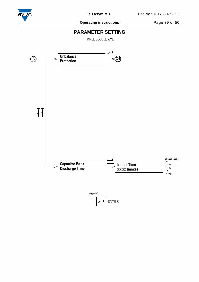
Page 39
ESTAsym MD Doc.No.: 13173 - Rev. 02 Operating instructions Page 39 of 50
PARAMETER SETTING TRIPLE DOUBLE WYE
ENTER
Legend :
Unbalance Protection
C C1
Capacitor Bank Discharge Timer
Change enable
Change
Inhibit Time xx:xx [mm:ss]
Page 40
ESTAsym MD Doc.No.: 13173 - Rev. 02 Operating instructions Page 40 of 50
ENTER
Legend :
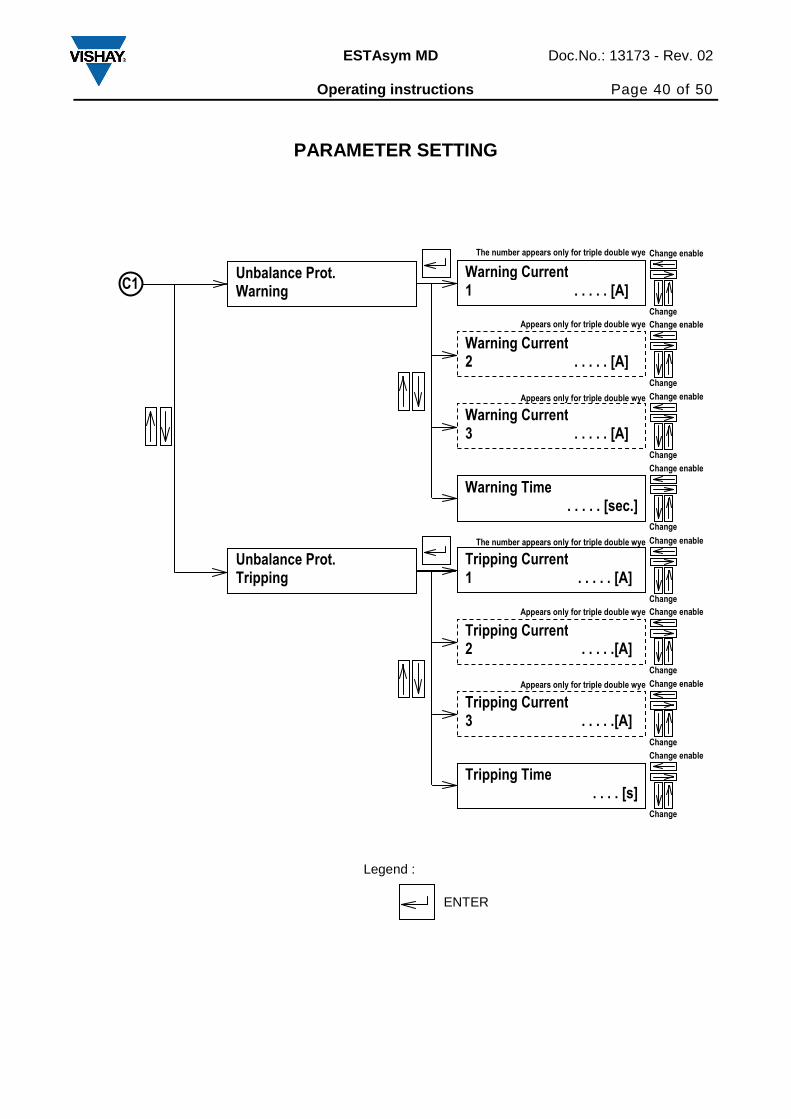
PARAMETER SETTING
Unbalance Prot. Warning
C1 Warning Current 1 . . . . . [A]
Warning Current 2 . . . . . [A]
Unbalance Prot. Tripping
Warning Current 3 . . . . . [A]
Warning Time . . . . . [sec.]
Change enable
Change
Change enable
Change
Change enable
Change
Change enable
Change
Tripping Current 1 . . . . . [A]
Tripping Current 2 . . . . .[A]
Tripping Current 3 . . . . .[A]
Tripping Time . . . . [s]
Change enable
Change
Change enable
Change
Change enable
Change
Change enable
Change
The number appears only for triple double wye
Appears only for triple double wye
Appears only for triple double wye
The number appears only for triple double wye
Appears only for triple double wye
Appears only for triple double wye
Page 41
ESTAsym MD Doc.No.: 13173 - Rev. 02 Operating instructions Page 41 of 50
ENTER
Legend :
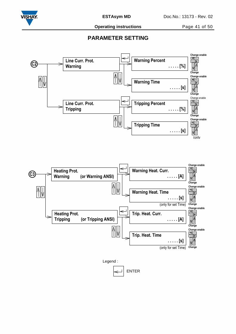
PARAMETER SETTING
Change enable
Change
Line Curr. Prot. Warning
C2
Line Curr. Prot. Tripping
Warning Percent . . . . . [%]
Warning Time . . . . . [s]
Change enable
Change
Change enable
Change
Tripping Percent . . . . . [%]
Tripping Time . . . . . [s]
Change enable
(only
Change enable
Change
Heating Prot. Warning (or Warning ANSI)
C3
Heating Prot. Tripping (or Tripping ANSI)
Warning Heat. Curr. . . . . . [A]
Warning Heat. Time . . . . . [s]
Change enable
Change
Change enable
Change
Trip. Heat. Curr. . . . . . [A]
Trip. Heat. Time . . . . . [s]
Change enable
Change
(only for set Time)
(only for set Time)
Page 42
ESTAsym MD Doc.No.: 13173 - Rev. 02 Operating instructions Page 42 of 50
ENTER
Legend :
Parameter setting
Change enable
Change
Ground Prot. Warning
C4
Ground Prot. Tripping
Warn. Gnd. Per. . . . . . [%]
Warn. Gnd. Time . . . . . [s]
Change enable
Change
Change enable
Change
Trip. Gnd. Per. . . . . . [%]
Trip. Gnd. Time . . . . . [s]
Change enable
Change
C5 Trip. Over Cur. >> (or >) . . . . . [A]
Trip. Over Time >> (or >) . . . . . [s]
Change enable
Change
Change enable
Change
C6Trip. Over Cur. RMS >> (or >) . . . . . [A]
Trip. Over Time RMS >> (or >) . . . . . [s]
Change enable
Change
Change enable
Change
Page 43
ESTAsym MD Doc.No.: 13173 - Rev. 02 Operating instructions Page 43 of 50
ENTER
Legend :
C7Trip. Under Cur.
. . . . . [A]
Trip. Under Time . . . . . [s]
Change enable
Change
Change enable
Change
Page 44
ESTAsym MD Doc.No.: 13173 - Rev. 02 Operating instructions Page 44 of 50
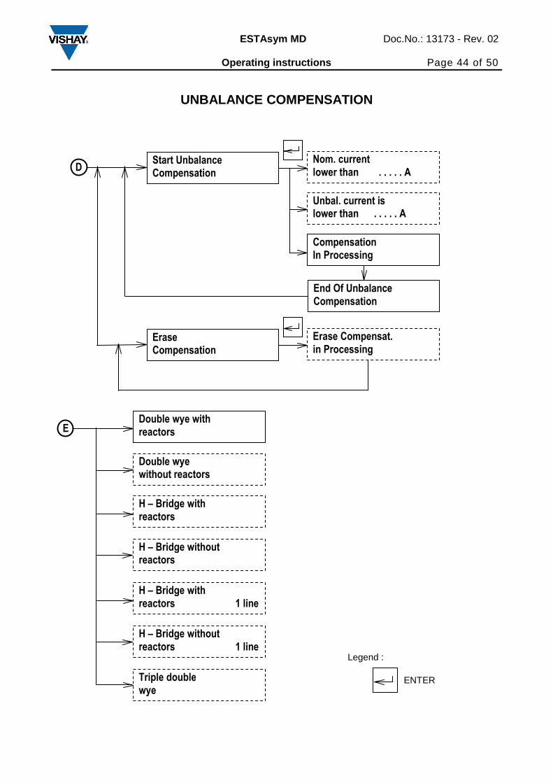
UNBALANCE COMPENSATION
D
End Of Unbalance Compensation
Start Unbalance Compensation
Compensation In Processing
Nom. current lower than . . . . . A
Unbal. current is lower than . . . . . A
Erase Compensation
Erase Compensat. in Processing
ENTER
Legend :
E Double wye with reactors
H – Bridge with reactors
Triple double wye
H – Bridge without reactors
Double wye without reactors
H – Bridge with reactors 1 line
H – Bridge without reactors 1 line
Page 45
ESTAsym MD Doc.No.: 13173 - Rev. 02 Operating instructions Page 45 of 50
14 Technical data
Current inputs
Rated current Four current inputs, each can be parameterized to
1A or 5A. Maximum current transformer ratio is 6000/x
Thermal current withstand
- Continuously 15A
- For 1 second 100A
Optron inputs 20 – 220 V DC
Rated frequency 50Hz / 60Hz
Power supply
Standard 100-375 V DC or 100-240 AC 50/60Hz
Option 18-75V DC
Power consumption 10 VA
Output contact rating
Continuous carry 8A / 265 V AC
0,3A / 300V DC
8A / 30V DC
Data transmission Interface RS 232 on the front panel or RS 485 and RS 232
on the rear panel. Baudrate is selectable by the PC software.
RS 485 is not used by the software now.
Metering of harmonics: Odd harmonics up to 25-th, even up to 6-th
Environmental conditions:
Operating temperature - 10 up to + 60°C
Storage temperature - 20 up to + 70° C
Dimensions 135 x 135 x 121 mm (w x h x d)
Degree of protection of the relay IP 54
Page 46
ESTAsym MD Doc.No.: 13173 - Rev. 02 Operating instructions Page 46 of 50
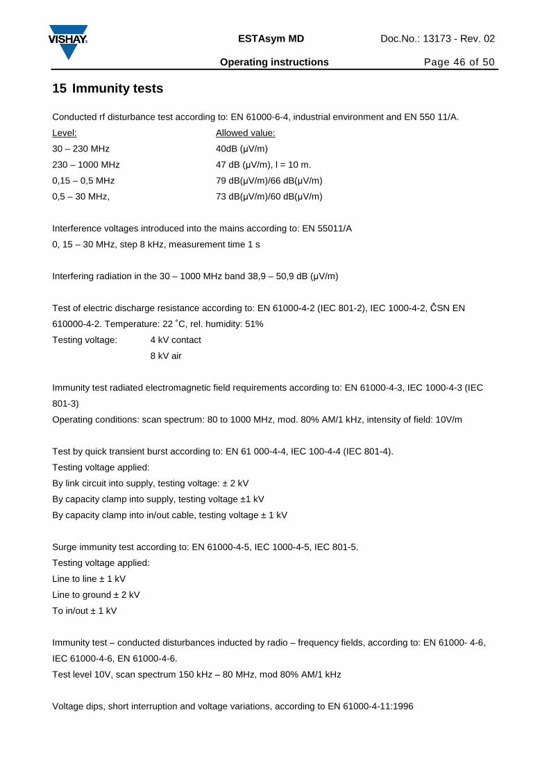
15 Immunity tests
Conducted rf disturbance test according to: EN 61000-6-4, industrial environment and EN 550 11/A.
Level: Allowed value:
30 – 230 MHz 40dB (µV/m)
230 – 1000 MHz 47 dB (µV/m), l = 10 m.
0,15 – 0,5 MHz 79 dB(µV/m)/66 dB(µV/m)
0,5 – 30 MHz, 73 dB(µV/m)/60 dB(µV/m)
Interference voltages introduced into the mains according to: EN 55011/A
0, 15 – 30 MHz, step 8 kHz, measurement time 1 s
Interfering radiation in the 30 – 1000 MHz band 38,9 – 50,9 dB (µV/m)
Test of electric discharge resistance according to: EN 61000-4-2 (IEC 801-2), IEC 1000-4-2, ČSN EN
610000-4-2. Temperature: 22 ˚C, rel. humidity: 51%
Testing voltage: 4 kV contact
8 kV air
Immunity test radiated electromagnetic field requirements according to: EN 61000-4-3, IEC 1000-4-3 (IEC
801-3)
Operating conditions: scan spectrum: 80 to 1000 MHz, mod. 80% AM/1 kHz, intensity of field: 10V/m
Test by quick transient burst according to: EN 61 000-4-4, IEC 100-4-4 (IEC 801-4).
Testing voltage applied:
By link circuit into supply, testing voltage: ± 2 kV
By capacity clamp into supply, testing voltage ±1 kV
By capacity clamp into in/out cable, testing voltage ± 1 kV
Surge immunity test according to: EN 61000-4-5, IEC 1000-4-5, IEC 801-5.
Testing voltage applied:
Line to line ± 1 kV
Line to ground ± 2 kV
To in/out ± 1 kV
Immunity test – conducted disturbances inducted by radio – frequency fields, according to: EN 61000- 4-6,
IEC 61000-4-6, EN 61000-4-6.
Test level 10V, scan spectrum 150 kHz – 80 MHz, mod 80% AM/1 kHz
Voltage dips, short interruption and voltage variations, according to EN 61000-4-11:1996
Page 47
ESTAsym MD Doc.No.: 13173 - Rev. 02 Operating instructions Page 47 of 50
Test level 70%Ut, duration 10 ms
Test level 40%Ut, duration 100ms
Test level 40%Ut duration 1000 ms
Page 48
ESTAsym MD Doc.No.: 13173 - Rev. 02 Operating instructions Page 48 of 50
16 Dimensions and cut-out details
Fig. 4 Dimensions and cut-out details
138,4 mm
138,
4 m
m
138 mm
138
mm
Panel Cut - Out
PC
113 mm 8 mm
Page 49
ESTAsym MD Doc.No.: 13173 - Rev. 02 Operating instructions Page 49 of 50
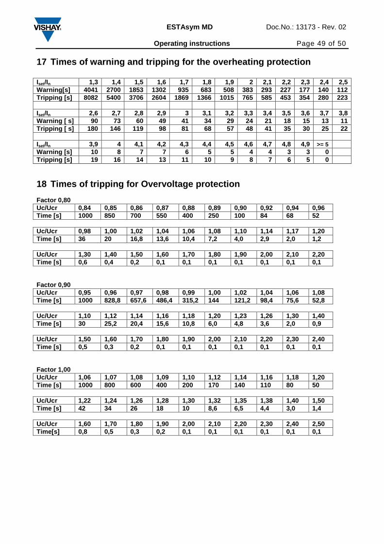
17 Times of warning and tripping for the overheatin g protection
Iset/In 1,3 1,4 1,5 1,6 1,7 1,8 1,9 2 2,1 2,2 2,3 2,4 2,5 Warning[s] 4041 2700 1853 1302 935 683 508 383 293 227 177 140 112 Tripping [s] 8082 5400 3706 2604 1869 1366 1015 765 585 453 354 280 223 Iset/In 2,6 2,7 2,8 2,9 3 3,1 3,2 3,3 3,4 3,5 3,6 3,7 3,8 Warning [ s] 90 73 60 49 41 34 29 24 21 18 15 13 11 Tripping [ s] 180 146 119 98 81 68 57 48 41 35 30 25 22 Iset/In 3,9 4 4,1 4,2 4,3 4,4 4,5 4,6 4,7 4,8 4,9 >= 5 Warning [s] 10 8 7 7 6 5 5 4 4 3 3 0 Tripping [s] 19 16 14 13 11 10 9 8 7 6 5 0
18 Times of tripping for Overvoltage protection Factor 0,80 Uc/Ucr 0,84 0,85 0,86 0,87 0,88 0,89 0,90 0,92 0,94 0,96 Time [s] 1000 850 700 550 400 250 100 84 68 52 Uc/Ucr 0,98 1,00 1,02 1,04 1,06 1,08 1,10 1,14 1,17 1,20 Time [s] 36 20 16,8 13,6 10,4 7,2 4,0 2,9 2,0 1,2 Uc/Ucr 1,30 1,40 1,50 1,60 1,70 1,80 1,90 2,00 2,10 2,20 Time [s] 0,6 0,4 0,2 0,1 0,1 0,1 0,1 0,1 0,1 0,1 Factor 0,90 Uc/Ucr 0,95 0,96 0,97 0,98 0,99 1,00 1,02 1,04 1,06 1,08 Time [s] 1000 828,8 657,6 486,4 315,2 144 121,2 98,4 75,6 52,8 Uc/Ucr 1,10 1,12 1,14 1,16 1,18 1,20 1,23 1,26 1,30 1,40 Time [s] 30 25,2 20,4 15,6 10,8 6,0 4,8 3,6 2,0 0,9 Uc/Ucr 1,50 1,60 1,70 1,80 1,90 2,00 2,10 2,20 2,30 2,40 Time [s] 0,5 0,3 0,2 0,1 0,1 0,1 0,1 0,1 0,1 0,1 Factor 1,00 Uc/Ucr 1,06 1,07 1,08 1,09 1,10 1,12 1,14 1,16 1,18 1,20 Time [s] 1000 800 600 400 200 170 140 110 80 50 Uc/Ucr 1,22 1,24 1,26 1,28 1,30 1,32 1,35 1,38 1,40 1,50 Time [s] 42 34 26 18 10 8,6 6,5 4,4 3,0 1,4 Uc/Ucr 1,60 1,70 1,80 1,90 2,00 2,10 2,20 2,30 2,40 2,50 Time[s] 0,8 0,5 0,3 0,2 0,1 0,1 0,1 0,1 0,1 0,1
Page 50
ESTAsym MD Doc.No.: 13173 - Rev. 02 Operating instructions Page 50 of 50
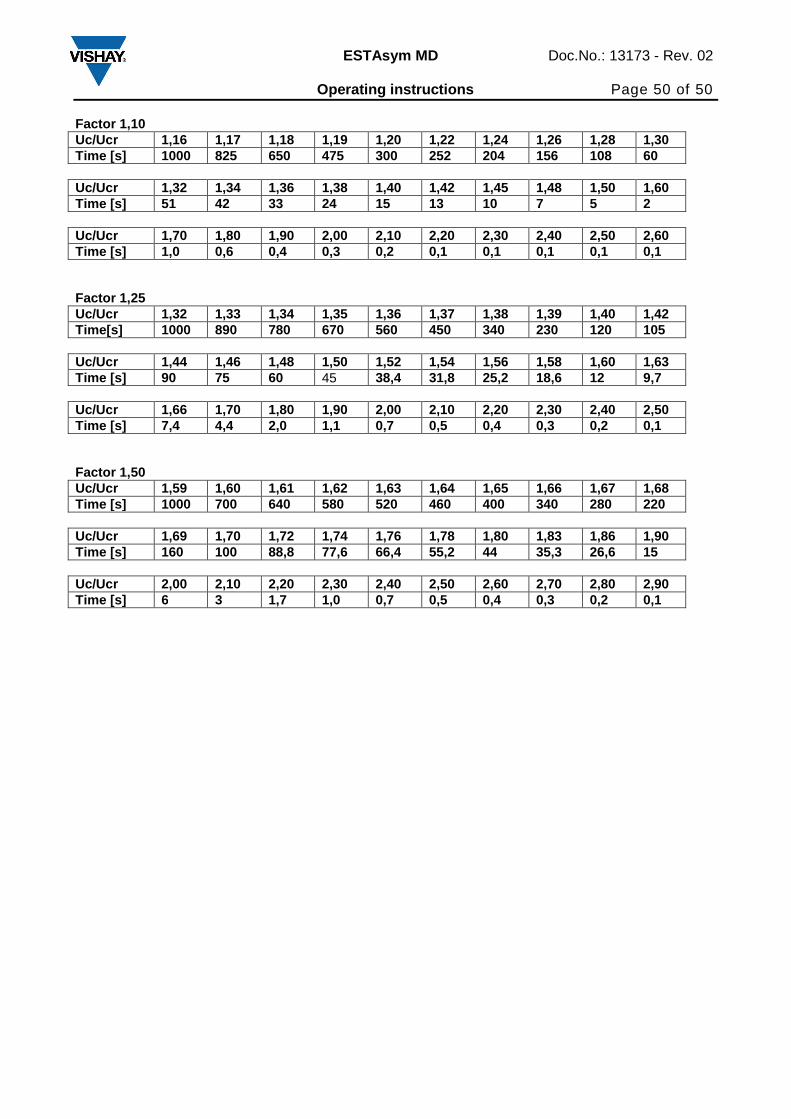
Factor 1,10 Uc/Ucr 1,16 1,17 1,18 1,19 1,20 1,22 1,24 1,26 1,28 1,30 Time [s] 1000 825 650 475 300 252 204 156 108 60 Uc/Ucr 1,32 1,34 1,36 1,38 1,40 1,42 1,45 1,48 1,50 1,60 Time [s] 51 42 33 24 15 13 10 7 5 2 Uc/Ucr 1,70 1,80 1,90 2,00 2,10 2,20 2,30 2,40 2,50 2,60 Time [s] 1,0 0,6 0,4 0,3 0,2 0,1 0,1 0,1 0,1 0,1 Factor 1,25 Uc/Ucr 1,32 1,33 1,34 1,35 1,36 1,37 1,38 1,39 1,40 1,42 Time[s] 1000 890 780 670 560 450 340 230 120 105 Uc/Ucr 1,44 1,46 1,48 1,50 1,52 1,54 1,56 1,58 1,60 1,63 Time [s] 90 75 60 45 38,4 31,8 25,2 18,6 12 9,7 Uc/Ucr 1,66 1,70 1,80 1,90 2,00 2,10 2,20 2,30 2,40 2,50 Time [s] 7,4 4,4 2,0 1,1 0,7 0,5 0,4 0,3 0,2 0,1 Factor 1,50 Uc/Ucr 1,59 1,60 1,61 1,62 1,63 1,64 1,65 1,66 1,67 1,68 Time [s] 1000 700 640 580 520 460 400 340 280 220 Uc/Ucr 1,69 1,70 1,72 1,74 1,76 1,78 1,80 1,83 1,86 1,90 Time [s] 160 100 88,8 77,6 66,4 55,2 44 35,3 26,6 15 Uc/Ucr 2,00 2,10 2,20 2,30 2,40 2,50 2,60 2,70 2,80 2,90 Time [s] 6 3 1,7 1,0 0,7 0,5 0,4 0,3 0,2 0,1