1 CE-632 Foundation Analysis and Design 1 Design Settlement of Foundation Settlement of Foundation Foundation Analysis and Design: Dr. Amit Prashant Settlement Settlement Settlement S = S e + S c + S s Immediate Settlement S e Primary Consolidation S c Secondary Consolidation S s 2 Immediate Settlement: Occurs immediately after the construction. This is computed using elasticity theory (Important for Granular soil) Primary Consolidation: Due to gradual dissipation of pore pressure induced by external loading and consequently expulsion of water from the soil mass, hence volume change. (Important for Inorganic clays) Secondary Consolidation: Occurs at constant effective stress with volume change due to rearrangement of particles. (Important for Organic soils) For any of the above mentioned settlement calculations, we first need vertical stress increase in soil mass due to net load applied on the foundation Foundation Analysis and Design: Dr. Amit Prashant Elasticity Elasticity 3
Transcript
1
CE-632Foundation Analysis and Design
1
Design
Settlement of FoundationSettlement of Foundation
Foundation Analysis and Design: Dr. Amit Prashant
SettlementSettlementSettlement
S = Se + Sc + Ss
ImmediateSettlement
Se
PrimaryConsolidation
Sc
SecondaryConsolidation
Ss
2
Immediate Settlement: Occurs immediately after the construction. This is computed using elasticity theory (Important for Granular soil)Primary Consolidation: Due to gradual dissipation of pore pressure induced by external loading and consequently expulsion of water from the soil mass, hence volume change. (Important for Inorganic clays)Secondary Consolidation: Occurs at constant effective stress with volume change due to rearrangement of particles. (Important for Organic soils)
For any of the above mentioned settlement calculations, we first need vertical stress increase in soil mass due to net load applied on the foundation
Vertical Stress: Rectangular AreaVertical Stress: Rectangular Area
9
4
Foundation Analysis and Design: Dr. Amit Prashant
Vertical Stress: Rectangular AreaVertical Stress: Rectangular Area
10
Foundation Analysis and Design: Dr. Amit PrashantPressure BulbPressure BulbSquare Footing Strip Footing
11
Foundation Analysis and Design: Dr. Amit Prashant
Pressure Pressure Bulb for Bulb for Square Square FoundationFoundation
12
5
Foundation Analysis and Design: Dr. Amit Prashant
Pressure Pressure Bulb for Bulb for CircularCircularFoundationFoundation
13
Foundation Analysis and Design: Dr. Amit Prashant
Newmark’sNewmark’s ChartChart
14
Influence Value
This Model is good for normally-consolidated, lightly overconsolidated clays, and variable deposits
Foundation Analysis and Design: Dr. Amit Prashant
Newmark’s ChartNewmark’s ChartPoint of stress calculation
Depth = z2
15
Determine the depth, z, where you wish to calculate the stress increaseAdopt a scale as shown in the figureDraw the footing to scale and place the point of interest over the center of the chartCount the number of elements that fall inside the footing, NCalculate the stress increase as:
Depth = z1
6
Foundation Analysis and Design: Dr. Amit Prashant
Westergaard’s MethodWestergaard’s MethodProvided solution for layered soilsPoint LoadsAssumption:Elastic soil mass is laterally reinfrced by numorous, closely spaced, horizontal sheets of negligible thickness but infinite rigidity, that allow only vertical movement but prevent the mass as a whole from undergoing any lateral
16
p g g ystrain.
( )
32
22 2
12z
Pz C r z
σπ
⎡ ⎤= ⎢ ⎥
+⎢ ⎥⎣ ⎦( )
1 22 1
C νν
−=
−
This Model is specially good for pre-compressed or overconsolidated clays
fI = influence factor: depends on the rigidity and shape of the foundation
sE = Avg elasticity modulus of the soil for (4B) depth below foundn level
Foundation Analysis and Design: Dr. Amit Prashant
Elastic settlement of FoundationElastic settlement of Foundation
24
9
Foundation Analysis and Design: Dr. Amit Prashant
Elastic settlement of FoundationElastic settlement of Foundation
E in kPa
25
Foundation Analysis and Design: Dr. Amit Prashant
Elastic settlement of FoundationElastic settlement of Foundation
26
Foundation Analysis and Design: Dr. Amit Prashant
Elastic settlement of FoundationElastic settlement of FoundationSoil Strata with Semi-infinite depth
27
10
Foundation Analysis and Design: Dr. Amit Prashant
Steinbrenner’s Influence Factors for Settlement of the Corners of Steinbrenner’s Influence Factors for Settlement of the Corners of loaded Area loaded Area LxBLxB on Compressible Stratus of on Compressible Stratus of μμ = 0.5= 0.5, and Thickness , and Thickness HHtt
28
Foundation Analysis and Design: Dr. Amit Prashant
Strain Influence Factor Method for Sandy Soil: Strain Influence Factor Method for Sandy Soil: SchmertmannSchmertmannand Hartman (1978)and Hartman (1978)
( )2
1 20
zz
e fs
IS C C q D zE
γ= − Δ∑1C = Correction factor for foundation depth
( ){ }1 0.5 f fD q Dγ γ⎡ ⎤− −⎣ ⎦
2C = Correction factor for creep effects
q For square and circular foundation:
( )1 0.2 log time in years 0.1⎡ ⎤+⎣ ⎦
29
q
For foundation with L/B >10:
Interpolate the values for 1 < L/B < 10
Foundation Analysis and Design: Dr. Amit Prashant
ExampleExample
( )2
1 20
zz
e fs
IS C C q D zE
γ= − Δ∑231.39fD kN mγ =
For square and circular foundations
30
3.5s cE q≈
2.5s cE q≈
For rectangular foundations
800 in kPasE N ′′≈Correlation with SPT data:
11
Foundation Analysis and Design: Dr. Amit Prashant
Burland and Burbidge’s Method for Sandy SoilsBurland and Burbidge’s Method for Sandy Soils
Depth of Stress Influence (z'):
( )0.751.04 ,where B is in metersz B′ =If N60'‘ is constant or increasing with depth, then If N60'‘ is decreasing with depth, use smaller of
( )2
1 25 L B⎡ ⎤Elastic Settlement (Se):
where B is in meters
2 and Thickness of soft layer below foundationz B z z′ ′ ′′= = =
31
( )( )1 2 3
1.250.25e
L BS Bq
L Bα α α
⎡ ⎤′= ⎢ ⎥
+⎢ ⎥⎣ ⎦
where B is in meters and is in kPaq′
1α = 0.0047 for NC sand0.0016 for OC sand with qna ≤ po‘0.0047 for OC sand with qna ≤ po‘
( )( )
1.42
1.4
1.71
0.57
N
N
α ′′=
′′=
Compressibility Index: for NC sand
for OC sand
3 2 1z zz z
α′′ ′′⎛ ⎞= − ≤⎜ ⎟′ ′⎝ ⎠
for NC sand and for OC sand with qna ≤ po‘
for OC sand with qna ≤ po‘0.67na oq q p′ ′= −naq q′ =
Foundation Analysis and Design: Dr. Amit Prashant
Settlement due to Primary ConsolidationSettlement due to Primary Consolidation
log log1 1
s c c c c o avc
o o o c
C H C HSe e
σ σ σσ σ⎛ ⎞ ⎛ ⎞′ ′ ′+ Δ
= +⎜ ⎟ ⎜ ⎟′ ′+ +⎝ ⎠ ⎝ ⎠
log1
s c o avc
o o
C HSe
σ σσ
⎛ ⎞′ ′+ Δ= ⎜ ⎟′+ ⎝ ⎠
log1
c c o avc
o o
C HSe
σ σσ
⎛ ⎞′ ′+ Δ= ⎜ ⎟′+ ⎝ ⎠
For NC clay
For OC clay ( )o av cσ σ σ′ ′ ′+ Δ <
For OC clay ( )o c o avσ σ σ σ′ ′ ′ ′< < + Δ
( )c o o avσ σ σ σ′ ′ ′ ′< < + Δ
32
⎝ ⎠ ⎝ ⎠
oσ ′ = Average effective vertical stress before construction
avσ ′Δ = Average increase in effective vertical stress
cσ ′ = Effective pre-consolidation pressure
oe = Initial void ratio of the clay layer
cC = Compression Index
sC = Swelling IndexcH = Thickness of the clay layer
( )1 46av t m bσ σ σ σ′ ′ ′ ′Δ = Δ + Δ + Δ
tσ ′Δ
bσ ′Δ
mσ ′Δ
Foundation Analysis and Design: Dr. Amit Prashant
Settlement Correction for Effect of 3Settlement Correction for Effect of 3--D ConsolidationD Consolidation
33
( ) ( )3 1c cD DS Sλ=
12
Foundation Analysis and Design: Dr. Amit Prashant
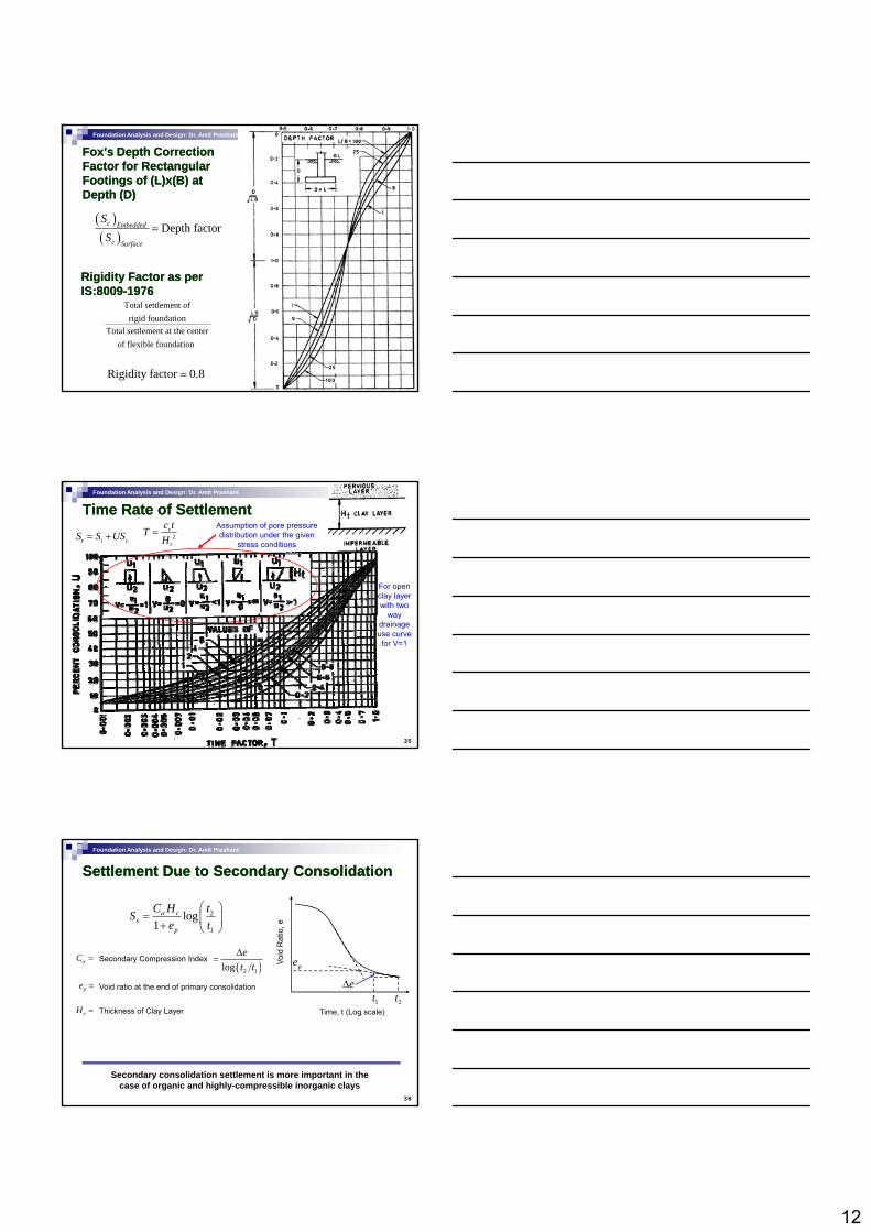
Fox’s Depth Correction Fox’s Depth Correction Factor for Rectangular Factor for Rectangular Footings of (L)x(B) at Footings of (L)x(B) at Depth (D)Depth (D)
( )( )
Depth factorc Embedded
c Surface
SS
=
34
Rigidity Factor as per Rigidity Factor as per IS:8009IS:8009--19761976
Total settlement of rigid foundation
Total settlement at the center of flexible foundation
Rigidity factor 0.8=
Foundation Analysis and Design: Dr. Amit Prashant
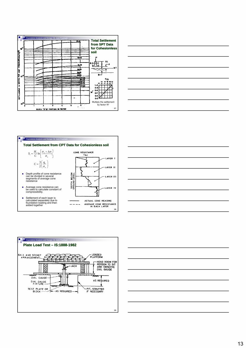
Time Rate of SettlementTime Rate of Settlement
t i cS S US= + 2v
t
c tTH
=
For open clay layer with two
way
Assumption of pore pressure distribution under the given
stress conditions
35
way drainage use curve for V=1
Foundation Analysis and Design: Dr. Amit Prashant
Settlement Due to Secondary ConsolidationSettlement Due to Secondary Consolidation
2
1
log1
cs
p
C H tSe t
α ⎛ ⎞= ⎜ ⎟+ ⎝ ⎠
Cα = Secondary Compression Index( )2 1log
et tΔ
= Void
Rat
io, e
pe
36
pe =
( )2 1
Time, t (Log scale)1t 2t
eΔVoid ratio at the end of primary consolidation
cH = Thickness of Clay Layer
Secondary consolidation settlement is more important in the case of organic and highly-compressible inorganic clays
13
Foundation Analysis and Design: Dr. Amit Prashant
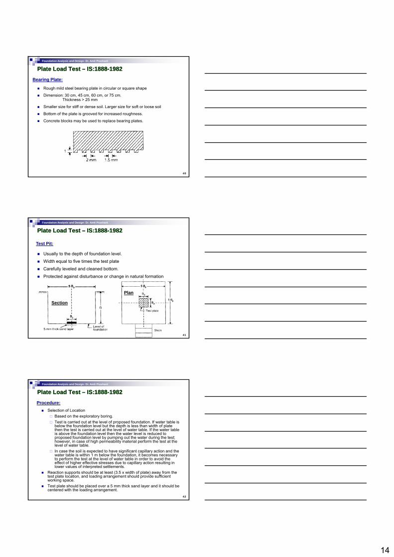
Total Settlement Total Settlement from SPT Data from SPT Data for for CohesionlessCohesionlesssoilsoil
37
Multiply the settlement by factor W'
Foundation Analysis and Design: Dr. Amit Prashant
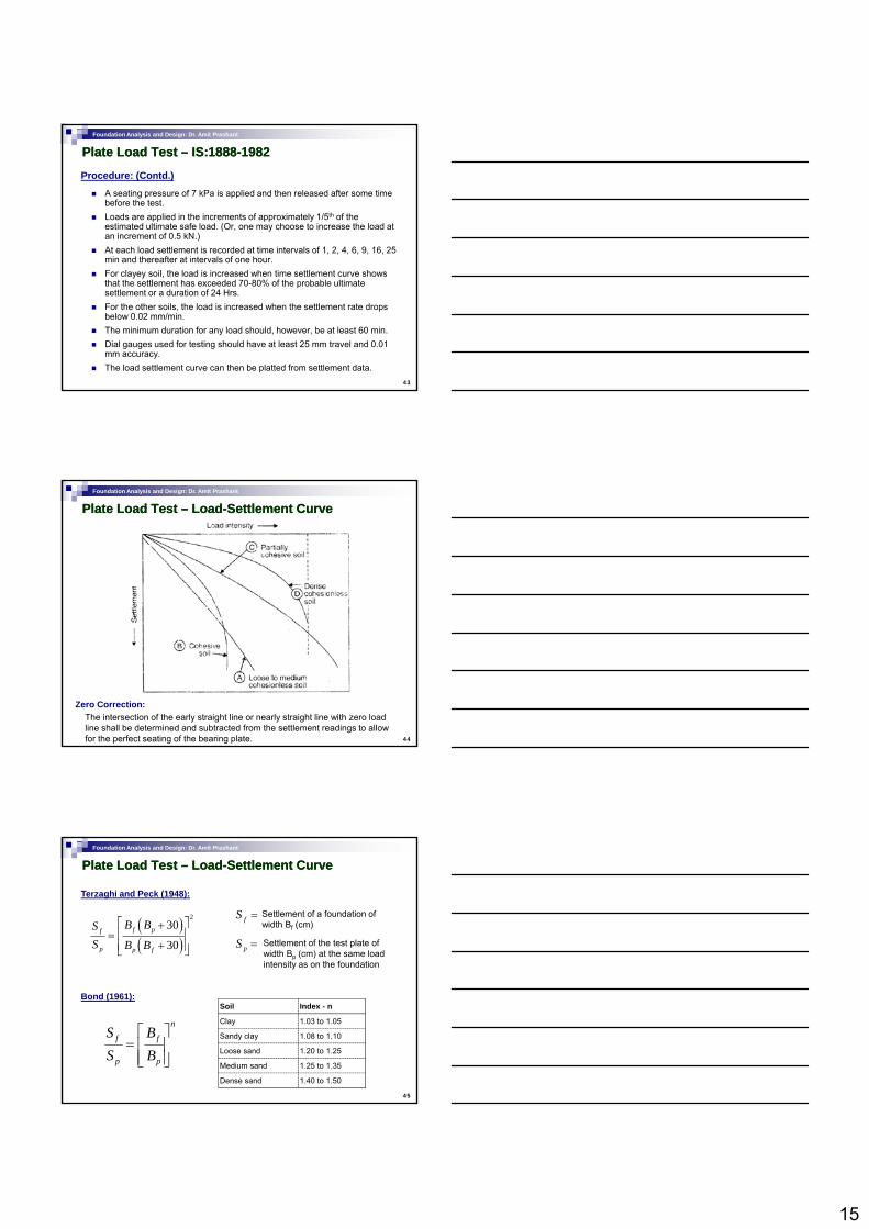
Total Settlement from CPT Data for Total Settlement from CPT Data for CohesionlessCohesionless soilsoil
32
c
o
qCσ⎛ ⎞
= ⎜ ⎟⎝ ⎠
lnt ot
o
HSC
σ σσ
⎡ ⎤+ Δ= ⎢ ⎥
⎣ ⎦
Depth profile of cone resistance
38
Depth profile of cone resistance can be divided in several segments of average cone resistance
Average cone resistance can be used to calculate constant of compressibility.
Settlement of each layer is calculated separately due to foundation loading and then added together
Foundation Analysis and Design: Dr. Amit Prashant
Plate Load Test Plate Load Test –– IS:1888IS:1888--19821982
39
14
Foundation Analysis and Design: Dr. Amit Prashant
Plate Load Test Plate Load Test –– IS:1888IS:1888--19821982
Bearing Plate:
Rough mild steel bearing plate in circular or square shape
Dimension: 30 cm, 45 cm, 60 cm, or 75 cm. Thickness > 25 mm
Smaller size for stiff or dense soil. Larger size for soft or loose soil
Bottom of the plate is grooved for increased roughness.
40
Concrete blocks may be used to replace bearing plates.
Foundation Analysis and Design: Dr. Amit Prashant
Plate Load Test Plate Load Test –– IS:1888IS:1888--19821982
Test Pit:
Usually to the depth of foundation level.
Width equal to five times the test plate
Carefully leveled and cleaned bottom.
Protected against disturbance or change in natural formation
41
Section
Plan
g g
Foundation Analysis and Design: Dr. Amit Prashant
Plate Load Test Plate Load Test –– IS:1888IS:1888--19821982
Procedure:Selection of Location
Based on the exploratory boring.Test is carried out at the level of proposed foundation. If water table is below the foundation level but the depth is less than width of plate then the test is carried out at the level of water table. If the water table is above the foundation level then the water level is reduced to proposed foundation level by pumping out the water during the test;
f f
42
however, in case of high permeability material perform the test at the level of water table.In case the soil is expected to have significant capillary action and the water table is within 1 m below the foundation, it becomes necessary to perform the test at the level of water table in order to avoid the effect of higher effective stresses due to capillary action resulting in lower values of interpreted settlements.
Reaction supports should be at least (3.5 x width of plate) away from the test plate location, and loading arrangement should provide sufficient working space.Test plate should be placed over a 5 mm thick sand layer and it should be centered with the loading arrangement.
15
Foundation Analysis and Design: Dr. Amit Prashant
Plate Load Test Plate Load Test –– IS:1888IS:1888--19821982
Procedure: (Contd.)
A seating pressure of 7 kPa is applied and then released after some time before the test.Loads are applied in the increments of approximately 1/5th of the estimated ultimate safe load. (Or, one may choose to increase the load at an increment of 0.5 kN.)At each load settlement is recorded at time intervals of 1, 2, 4, 6, 9, 16, 25
i d th ft t i t l f h
43
min and thereafter at intervals of one hour.For clayey soil, the load is increased when time settlement curve shows that the settlement has exceeded 70-80% of the probable ultimate settlement or a duration of 24 Hrs.For the other soils, the load is increased when the settlement rate drops below 0.02 mm/min.The minimum duration for any load should, however, be at least 60 min.Dial gauges used for testing should have at least 25 mm travel and 0.01 mm accuracy.The load settlement curve can then be platted from settlement data.
Foundation Analysis and Design: Dr. Amit Prashant
Plate Load Test Plate Load Test –– LoadLoad--Settlement CurveSettlement Curve
44
Zero Correction:The intersection of the early straight line or nearly straight line with zero load line shall be determined and subtracted from the settlement readings to allow for the perfect seating of the bearing plate.
Foundation Analysis and Design: Dr. Amit Prashant
Plate Load Test Plate Load Test –– LoadLoad--Settlement CurveSettlement Curve
Terzaghi and Peck (1948):
( )( )
230
30f pf
p p f
B BSS B B
⎡ ⎤+⎢ ⎥=
+⎢ ⎥⎣ ⎦
fS = Settlement of a foundation of width Bf (cm)
pS = Settlement of the test plate of width Bp (cm) at the same load intensity as on the foundation
45
Bond (1961):
n
f f
p p
S BS B
⎡ ⎤= ⎢ ⎥⎢ ⎥⎣ ⎦
Soil Index - n
Clay 1.03 to 1.05
Sandy clay 1.08 to 1.10
Loose sand 1.20 to 1.25
Medium sand 1.25 to 1.35
Dense sand 1.40 to 1.50
16
Foundation Analysis and Design: Dr. Amit Prashant
Plate Load Test: Some ConsiderationsPlate Load Test: Some ConsiderationsThe width of test plate should not be less than 30 cm. It is experimentally shown that the load settlement behavior of soil is qualitatively different for smaller widths.The settlement influence zone is much larger for the real foundation sizes than that for test plate, which may lead to gross
i i t t ti f t d ttl t
Soft soil layer
46
misinterpretation of expected settlement for proposed foundation.The foundation settlements in loose sands are usually much larger than what is predicted by plate load test.Plate load test is relatively short duration test and gives mostly the immediate settlements. In case of granular soils the immediate settlement is close to total settlements. However, due to considerable consolidation settlement in case of cohesive soils, the plate load test becomes irrelevant in such case. Although the following relationship is suggested for interpreting the settlements in cohesive soils, it can not be used seriously for design.
f f
p p
S BS B
=
Foundation Analysis and Design: Dr. Amit Prashant
Plate Load Test: Bearing CapacityPlate Load Test: Bearing CapacityIn case of dense cohesionless soil and highly cohesive soils ultimate bearing capacity may be estimated from the peak load in load-settlement curve.In case of partially cohesive soils and loose to medium dense soils the ultimate bearing capacity load may be estimated by assuming the load settlement curve so as to be a bilinear relationship.
47
Foundation Analysis and Design: Dr. Amit Prashant
Plate Load Test: Bearing CapacityPlate Load Test: Bearing CapacityA more precise determination of bearing capacity load is possible if the load-settlement curve is plotted in log-log scale and the relationship is assume to be bilinear. The intersection point is taken as the yield point or the bearing capacity load.
48
uf f
up p
q Bq B
=For cohesioless soil
uf upq q=For cohesive soil
17
Foundation Analysis and Design: Dr. Amit Prashant
Modulus of Modulus of SubSub--grade grade ReactionReaction
Differential settlement should not exceed 50% of the total settlement calculated for the foundation.
Considering the sizes of different footing, the following criteria is suggested for buildings:
For raft foundation the requirements shall be more stringent and they may designed for the following criteria
Differential settlement of footing 75% of max calculated settlement of footing>
50
g
Differential settlement of raft footing 37% of max calculated settlement of raft footing>
δΔΔ
L
Δ= maximum settlement
δ= differential settlement
δ/Δ = angular distortion
Allowable maximum and differential settlements as prescribed by IS:1904-1986 are given on the next slide
Foundation Analysis and Design: Dr. Amit Prashant
51
18
Foundation Analysis and Design: Dr. Amit Prashant
Rotation of Footings Subjected to MomentRotation of Footings Subjected to MomentFootings subjected to moment will have the tendency to rotate and the amount of rotation can be estimated by assuming that the footing is supported on a bed of springs and using the modulus of sub-grade reaction theory.
Modulus of sub-grade reaction:
EQ
52
( )21sEk
B ν=
−
L
M
Moment about the base due to soil reaction:
( )32
02 . .
12B LB kM L k dx θθ= =∫
Foundation Analysis and Design: Dr. Amit Prashant
Rotation of Footings Subjected to MomentRotation of Footings Subjected to Moment
IS Code recommendation: Use total settlement correlations with SPT data to determine safe bearing pressure.
Correlations for raft foundations:Rafts are mostly safe in bearing capacity and they do not show much differential settlements as compared to isolated foundations.
59
( ) 20.7 3 n w D aq N R C S kN mρ ′′ ′= −Teng’s Correlation:
Peck, Hanson, and Thornburn (1974): 20.88 a net w aq C N S kN m− ′′=
Correlations using CPT data:Meyerhof’s correlations may be used by substituting qc/2 for N, where qc is in kg/cm2.
Foundation Analysis and Design: Dr. Amit Prashant
Net vs. Gross Allowable Bearing PressureNet vs. Gross Allowable Bearing Pressure