234
Certified Hot Mix Asphalt Field Supervisor Manual

Certified Hot Mix
Asphalt Field Supervisor Manual

10/1/13
Table of Contents
Chapter One - Hot Mix Asphalt Paving Inspection
Terminology………………………………………………………… 1-1
Prerequisites………………………………………………………… 1-1
Duties…………………………..…………………………………… 1-2
Chain of Command…………………………………………………. 1-3
INDOT Project/District Level
Central Office
Contractor
Communication……………………………………………………… 1-4
Accurate Communication
The Three Key Activities of Accurate Communication
Communication in Specific Situations
When Instructing Your Crew
Meetings
Telephone Conversations
Safety……………………………………………………………….. 1-14
Hazards
Possible Injuries
Safety Precautions
Terms Related to Hot Mix Asphalt…………………………………. 1-20
Chapter Two - Mix Composition
Quality Control/Quality Assurance…………………………………. 2-1
Quality Control Plan
Quality Assurance Procedures
Materials
Design Mix Formula/Job Mix Formula
Hot Mix Asphalt (HMA)……………………………………………… 2-7
Quality Control
Pay Item
Design Mix Formula/Job Mix Formula
Miscellaneous Mix Criteria
Acceptance of Mixtures
Stone Mastic Asphalt ……………………………………………….. 2-8
Chapter Three -- Quality Assurance Procedures
Design Mix Formula……………………………………………………… 3-1
Lot/Sublot – QC/QA HMA and SMA……..……………………….…… 3-1
Types of Samples…………………………………………………………. 3-3
Plate Samples
Truck Samples
Core Samples
Appeal Samples
Methods of Acceptance Sampling………………………………………… 3-5
Random Numbers
Plate Samples
Truck Sampling
Core Sampling
Adjustment Period – QC/QA HMA ……………………………………… 3-17
Mixture Acceptance………………………………………………………. 3-17
QC/QA HMA
HMA
Pay Factors – QC/QA HMA (Dense Graded Mixture ≥ 1 Lot)…………… 3-20
PWL-Mixture
PWL-Density
Pay Factors
Adjustment Quantity – QC/QA HMA ≥ 1 lot……………………………. 3-31
Pay factors – QC/QA HMA (Dense Graded Mixture < 1 Lot
and Open Graded Mixtures)……………………………… 3-35
Mixture
Density
Adjustment Quantity –QC/QA HMA < 1 Lot and Open Graded Mixtures 3-39
Mix Appeal – QC/QA HMA……………………………………………… 3-42
Smoothness………………………………………………………………… 3-43
Procedures
Profilograph Exemptions
Quality Assurance Adjustments
Chapter Four – Quality Control Procedures
Contractor Personnel………………………………………………… 4-1
QCP Manager
QCP Site Manager
Quality Control Technician
Milling……………………………………………………………… 4-2
Milling Plan
Equipment
Testing
Process Balance…………………………………………………….. 4-3
Transportation of Mixture…………………………………………… 4-8
Truck Bed Cover
Unloading
Transfer Vehicles
Paving……………………………………………………………….. 4-8
Paving Plan
Material Feed System
Grade and Slope
Joints
Asphalt Materials
Joint Compaction……………………………………………………. 4-9
Materials Sampling and Testing……………………………………... 4-9
Mixture Properties
Mixture Temperature at Paver
Density
Coring
Smoothness
Response to Test Results……………………………………………… 4-10
Pavement Smoothness………………………………………………… 4-10
Documentation………………………………………………………… 4-10
Quality Control Plan…………………………………………………... 4-10
QCP Approval
QCP Addenda
Chapter Five - Traffic Control
Basic Setup………………….….…………………………………… 5-1
Continual Inspection ……………………………………………….. 5-7
Temporary Pavement Markings…………………………………….. 5-7
Chapter Six - Preparation of Surface
Subgrade Treatment………………………………………………….. 6-1
Proofrolling…………………………………………………………... 6-2
Milling……………………………………………………………….. 6-2
Patching……………………………………………………………… 6-4
Wedge and Level……………………………………………………. 6-6
Base Widening………………………………………………………. 6-7
Cleaning……………………………………………………………... 6-8
Tacking……………………………………………………………… 6-9
Application
Curing

Chapter Seven - Mix Placement and Compaction
Weather Limitations…………………………………………………….. 7-1
Asphalt Materials……………………………………………………….. 7-2
Prime Coats
Tack Coats
Base Seals
Fog Seals
Joint Adhesives
Distributor
Mixture Transportation………………………………………………….. 7-4
Haul Trucks
Material Transfer Vehicles
Mix Temperature and Appearance……………………………………… 7-7
Placement of Mixture……………………………………………………. 7-8
Pavers
Paver Operation
Start-Up
Alignment
Grade and Slope Control
Transverse Joints
Longitudinal Joints
Widening Machines
Care and Cleaning of Pavers
Paving Crew Responsibilities
Compaction………………………………………………………….. 7-28
Rollers
Compaction of HMA
Specified Rollers
Plant Production – Number of Rollers
Compaction Controlled by Density
Widening
Rolling Patterns
Roller Operator Responsibilities
Chapter Eight - Paving Troubleshooting
Problems Observed of the Mixture in the Trucks…………………… 8-1
Free Asphalt on Mix
Free Dust on Mix
Large Aggregate Uncoated
Mixture Not Uniform
Mixture Fat on One Side
Mixture Flattens
Mixture Burned
Mixture Brown or Gray
Mixture Too Fat
Mixture Smokes

Mixture Steams
Mixture Appears Dull
Problems Observed During Paving…………………………………..
8-6
Bleeding
Transverse Joints – Improper Elevation Across Joint
Transverse Joints – Rough Uneven Joint
Screed Marks
Surface Texture Fluctuation
Tearing of Mat – Full Width
Tearing of Mat – Center
Tearing of Mat – Edge
Thickness and Mat Quality Variations
Wavy Surface – Long Waves
Wavy Surface – Ripples, Short Waves
Problems Observed During Compaction………………………………. 8-19
Checking Under Roller
Mat Shoving Ahead of Roller
Roller Marks
Unsatisfactory Compaction
Chapter Nine - Thickness and Tonnage Control
Mixture Adjustment Factor…………………………………………. 9-1
Checking Mat Thickness……………………………………………. 9-2
Determining Mat Thickness
Depth Checks
Actual Rate of Spread……………………………………………….. 9-3
Stationing
Weigh Tickets
Computing Rates of Spread
Chapter Ten – Seal Coat Placement
Types of Seal Coats………………………………………………….. 10-2
Quality Control Plan…………………………………………………. 10-3
Equipment……………………………………………………………. 10-3
Distributor
Chip Spreader
Pneumatic-Tire Roller
Rotary Power Broom
Surface Preparation………………………………………………….. 10-6
Aggregate Surface
Prime Coats
HMA Surfaces

Placement……………………………………………………………. 10-7
Weather Limitations
Traffic Control
Application of Asphalt Material
Application of Cover Aggregate
Application of Fog Seal
Application Rate Computations……………………………………… 10-13
Asphalt Material
Cover Aggregate
Fog Seal
Appendix A – Indiana Test Methods
ITM 580 Sampling HMA Mixtures
ITM 588 Percent Within limits (PWL)
ITM 802 Random Sampling
ITM 803 Contractor Quality Control Plans
ITM 812 Macrotexture of Milled Pavement
ITM 912 Profilographs
Appendix B – 2014 Standard Specifications
Appendix C – Project Checklists
Pre-Start-Up Project safety Checklist A
Start-Up Work Zone Evaluation Checklist B
Daily Production Checklist C
Shut Down Safety Checklist D
Completed Project Maintenance Checklist E
Appendix D – Process Balance Forms
Mix Delivery Production Calculation Form
Paving Production Calculation Form
Compaction Production Calculation Form

HMA FIELD SUPERVISOR PROGRAM INSTRUCTORS
Industry Representatives Dudley Bonte Rieth-Riley Const. Co . Bobby Bullock Gohmann Asphalt & Construction Brad Cruea Milestone Contractors Brian Crume E & B Paving Inc. Bill Knopf APAI Scott Sherrill Mamco Lynn Shireman Milestone Contractors Consultants Jim Scherocman Consulting Engineer INDOT Representatives Matt Beeson Asphalt Engineer (317) 610 7251 Office of Materials Management Ext: 215 Jeff James Construction Engineer (317) 232-5082 Construction Management & District Support Pat McCarty Supervisor (317) 899-8626 Work Zone Safety Ron Walker Manager (317) 610-7251 Office of Materials Management Ext. 204

2014
CERTIFIED HMA FIELD SUPERVISOR TRAINING COURSE AGENDA
Title-Time Subjects Instructors Reference
Tuesday Morning
Moderator: Ron Walker
Introduction
9:00 Opening Comments Ron Walker
to Agenda/Manual Update
9:30 Supervisor Requirements
Calculators
Communication
9:30 General Bill Knopf Chp 1
to Communication Jay Woenker
9:45
9:45 to 10:00 ** BREAK **
Quality Assurance Procedures and Mix Composition
10:00 Random Numbers Matt Beeson Chps 2 & 3
to Design Mix Formula Ron Walker
12:00 Lot/Sublot
Acceptance Samples
Adjustment Period
Mixture Acceptance
Density Acceptance
Smoothness Acceptance
Pay Factors – QC/QA HMA ≥ 1 Lot
Pay Factors – QC/QA HMA < 1 Lot
Adjustment Quantity
Mix Appeal
12:00 to 1:00 ** LUNCH **

Tuesday Afternoon
Moderator: Ron Walker
Quality Assurance Procedures and Mix Composition (cont.) Matt Beeson Chp 2 & 3
Ron Walker
1:00
to
2:00
2:00 to 2:15 **BREAK**
Quality Control Plan Requirements
2:15 ITM 803 Ron Walker Chp 4
to INDOT QCP Checklist
2:45
Contractor Quality Control Plans 2:45 Contractor Personnel Brad Cruea Chp 4
to Milling Bobby Bullock
4:30 Process Balance
Transportation of Mixture
Paving
Joint Compaction
Materials Sampling and Testing
Response to Test Results
Pavement Smoothness
Documentation
Quality Control Plan
Help Session
6:30 La Quinta Hotel, 21st St.

Wednesday Morning
Moderator: Ron Walker
Traffic Control
8:00 Basic Setup Pat McCarty Chp 5
to Continual Inspection
8:45 Temporary Pavement Markings
Preparation of Surface
8:45 Subgrade Treatment Brian Crume Chp 6
to Proofrolling Scott Sherrill
10:00 Milling
Patching
Wedge and Level
Base Widening
Cleaning
Tacking
10:00 to 10:15 ** BREAK **
Mix Placement and Compaction
10:15 Weather Limitations Steve Thieroff Chp 7
to Alignment
10:45 Paving Equipment
Grade and Slope Control
Mix Temperature and Appearance
Placement of Mix
Paver Operation
Compaction
Rolling Patterns
Paving Best Practices
10:45 Distributors Lynn Shireman Chp 7
to Pavers
12:00 Widening Machines
Rollers
Material Transfer Devices
12:00 to 1:00 **LUNCH**

Wednesday Afternoon
Moderator: Ron Walker
Paving Troubleshooting
1:00 Jim Scherocman Chp 8
to
2:00
2:00 to 2:15 ** BREAK **
Paving Troubleshooting (cont.)
2:15 Jim Scherocman Chp 8
to
3:15
Thickness and Tonnage Control 3:15 Mixture Adjustment Factor Dudley Bonte Chp 9
to Checking the Mat Thickness
4:30 Actual Rate of Speed
Help Session
6:30 La Quinta Hotel, 21st St.

Thursday Morning
Moderator: Matt Beeson
Course Exam
8:00
to
12:00

CERTIFIED HMA
FIELD SUPERVISOR
PROCEDURES and POLICIES
MANUAL
2012

1
INDOT
CERTIFIED HMA
FIELD SUPERVISOR
Objectives
The Indiana Department of Transportation (INDOT) has established a Quality Control/Quality
Assurance Program for the purpose of properly assigning INDOT and Producer responsibilities
for all aspects of the production of quality Hot Mix Asphalt. The QC/QA HMA Pavement
specifications require that the Quality Control Plan Field Manager be a Certified HMA Field
Supervisor.
The principal objective of the Certified HMA Field Supervisor Program is to provide the
necessary training to field personnel so that they may administer quality control of the HMA.
Knowledge of materials, HMA plants, mix delivery, compaction, smoothness, testing,
specifications and other field HMA related topics are provided to enhance the Supervisor’s
ability to meet the program requirements.
Administration
The training program is administered by INDOT, the Asphalt Pavement Association of Indiana
(APAI) and Purdue University. Specific duties of each agency include:
INDOT
1. Course Announcement
2. Writing and Maintenance of the Training Manual
3. Notification to Students of Examination Results
4. Mailing Certificates
5. Maintenance of Certified HMA Field Supervisor List
6. Retesting
7. Recertification
APAI
1. Training Facility Arrangements
2. Meal and Refreshment Arrangements
3. Providing Training Course Materials
4. Miscellaneous Administrative Tasks
Purdue University
1. Registration of Students
2. Manual Printing
3. Distribution of Funds
4. Grading the Examination
5. Certificate Preparation
6. Continuing Education Units
7. Miscellaneous Administrative Tasks

2
Program Committee
The Program Committee acts as the steering committee which establishes the needs for the
certification program and provides technical assistance for course materials and examinations.
The committee is composed of representatives from INDOT, FHWA, APAI, and Purdue
University.
Certification Committee
The Certification Committee is responsible for revocation or suspension of certifications. Their
tasks include reviewing the violations of standard policies, rendering judgement of the
seriousness of the violation, and hearing any subsequent appeal. The committee is composed of
the following members:
Manager, Office of Materials Management
1 Representative of Purdue University
1 Representative appointed by the APAI Training Committee
Certification Requirements
An individual is required to pass a written examination to become certified. Participation in the
certification training course is required to take the examination. Also, verification of attendance
of the OSHA 10 or OSHA 30 training course on construction safety is required for certification.
Training Course Announcement
The announcement for the training course will be made by December 1 of each year that the
course is offered.
Certification Examination
The certification examination is given upon completion of the training course. The examination
time is limited to a maximum duration of three hours and the examination is open book/open
note. There are two parts of the examination. Part I consists of multiple choice questions and
Part II consists of word problems and other numerical calculations. A minimum score of 70
percent is required on each part to pass the examination. Notification of the examination results
will be made within 10 days of the examination date.
A technician that has failed the certification examination will be allowed one retake of the
examination. Only the part(s) failed are required to be retaken. A duration of 1 hour for Part I
and 2 hours for Part II is allowed. The retake examination will be open book/open note and
consist of a format similar to the original examination. The retake examination will be given at
the INDOT Office of Materials Management within 30 days of notification of the technician's
results of the original examination. A minimum score of 70 percent on each part is required to
pass the retake examination. Technicians failing either part of the retake examination will be
required to participate in the training course and pass the examination to become certified.

3
The examinations will be retained by Purdue University for a period of one year after such time
the examinations will be destroyed. Examinations may be reviewed in the presence of an
INDOT representative within one year of the examination date. Arrangements for review of the
examination shall be made with INDOT.
Recertification Requirements
The certification is valid for three years as determined from the date of initial issuance.
Recertification will require obtaining 12 credits and attending a recertification refresher course or
by passing a written examination. The 12 credits may be obtained as follows:
QCP Field Manager of one or more INDOT
contracts in one construction season …………………………………. 4 credits
Consultant Project Manager of one or more INDOT
contracts in one construction season ………………………………… 4 credits
The recertification refresher course will include a condensed version of the certification training
course. There will be no fee for the recertification refresher course.
If the certification is not renewed, the certification will expire. Renewal of the certification may
be made within the subsequent year after expiration by passing the recertification examination or
retake examination, if required. Renewal of the certification after one year from the expiration
of the certification will require review by the Certification Committee to determine the
certification requirements.
Notification of the recertification procedures will be made prior to the expiration of the
certification. Applying for certification renewal and verification of the required recertification
credits using the form in Appendix A are the responsibility of each individual. A current address
will be on file with INDOT. Any address revision or the recertification credit form is required to
be sent to:
Asphalt Engineer
Indiana Department of Transportation
Office of Materials Management
120 S. Shortridge Rd.
Indianapolis, IN 46219
Fax: 317-356-9351
Recertification Examination
The recertification examination is limited to two hours, is open book/open note, and will consist
of word problems and other numerical calculations. A minimum score of 70 percent is required
to pass the examination. Notification of the examination results will be made within 10 days of
the examination date.

4
One retake of the examination will be allowed if the recertification exam is failed. Two hours
will be allowed for the retake examination. The examination will be open book/open note and
consist of a format similar to the original recertification examination. The retake examination
will be given at the INDOT Office of Materials Management within 30 days of notification of
the results of the original recertification examination. A minimum score of 70 percent is
required to pass the retake examination. A failure of the retake examination will require
participation in the certification training course and passing the certification examination to
become certified.
The recertification examinations will be retained by Purdue University for a period of one year.
After that period the examinations will be destroyed. Examinations may be reviewed in the
presence of an INDOT representative within one year of the examination date. Arrangements for
review of the examination are required to be made with INDOT.
Fees
The fee for attending the certification training course will be established by the Program
Committee. The fee will cover a training manual, course materials, refreshments, and several
meals.
The refund policy for the certification course fee is as follows:
1. An administration fee of $100 will be charged for cancellation within 7 days of
the course.
2. Lack of attendance of the course will result in no refund of the fee.
3. Unforeseen emergencies that result in absences during the course will result in a
refund of the course fee.
Failure to pay the training course or examination fees will result in suspension of the
certification.
Cancellation Policy
If a scheduled certification or recertification refresher course is cancelled because of insufficient
class size, notification will be sent one week prior to the start of the course. The course fee for
the certification course will be reimbursed.
Continuing Education Units
Two continuing education units will be awarded for completion of the certification training
course and passing the examination. Purdue University will maintain the necessary files for
those individuals requesting that the continuing education units be recorded.
5
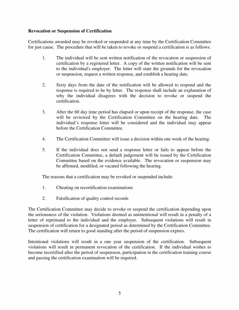
Revocation or Suspension of Certification
Certifications awarded may be revoked or suspended at any time by the Certification Committee
for just cause. The procedure that will be taken to revoke or suspend a certification is as follows:
1. The individual will be sent written notification of the revocation or suspension of
certification by a registered letter. A copy of the written notification will be sent
to the individual's employer. The letter will state the grounds for the revocation
or suspension, request a written response, and establish a hearing date.
2. Sixty days from the date of the notification will be allowed to respond and the
response is required to be by letter. The response shall include an explanation of
why the individual disagrees with the decision to revoke or suspend the
certification.
3. After the 60 day time period has elapsed or upon receipt of the response, the case
will be reviewed by the Certification Committee on the hearing date. The
individual’s response letter will be considered and the individual may appear
before the Certification Committee.
4. The Certification Committee will issue a decision within one week of the hearing.
5. If the individual does not send a response letter or fails to appear before the
Certification Committee, a default judgement will be issued by the Certification
Committee based on the evidence available. The revocation or suspension may
be affirmed, modified, or vacated following the hearing.
The reasons that a certification may be revoked or suspended include:
1. Cheating on recertification examinations
2. Falsification of quality control records
The Certification Committee may decide to revoke or suspend the certification depending upon
the seriousness of the violation. Violations deemed as unintentional will result in a penalty of a
letter of reprimand to the individual and the employer. Subsequent violations will result in
suspension of certification for a designated period as determined by the Certification Committee.
The certification will return to good standing after the period of suspension expires.
Intentional violations will result in a one year suspension of the certification. Subsequent
violations will result in permanent revocation of the certification. If the individual wishes to
become recertified after the period of suspension, participation in the certification training course
and passing the certification examination will be required.

6
Appendix A
HMA Field Supervisor
Recertification Credit Form
Name: ______________________________________________
Year: ____________________
I verify that the above-noted person was identified as the Quality Control Plan Field
Manager on HMA Pavement INDOT contract No.: ________________________.
___________________________________
Project Engineer/Supervisor
Send To: Asphalt Engineer
Indiana Department of Transportation
Office of Materials Management
120 S. Shortridge Rd.
Indianapolis, IN 46219
Fax: 317-356-9351

1 Hot Mix Asphalt Paving Supervision
Terminology
Prerequisites
Duties
Chain of Command INDOT Project/District Level
Central Office
Contractor
Communication Accurate Communication
The Three Key Activities of Accurate Communication
Communication in Specific Situations
When Instructing Your Crew
Meetings
Telephone Conservations
Safety Hazards
Possible Injuries
Safety Precautions
Terms Related to Hot Mix Asphalt

1-1
CHAPTER ONE:
HOT MIX ASPHALT PAVING SUPERVISION
The purpose of this course is to provide information on how to properly
construct Hot Mix Asphalt (HMA) pavements. Emphasis will be on
acquiring the skills and knowledge that a HMA Field Supervisor will need
to supervise and ensure construction of quality pavements in conformance
with the plans and Specifications. The construction of smooth, durable,
and safe highways requires careful planning and continuous monitoring.
This manual is intended to provide the best practices for the Certified
HMA Field Supervisor. Many of the techniques, procedures, and methods
provided are not applicable to all pavement circumstances, and other
methods may be used to meet the requirements of the specifications. The
manual is not to be considered part of the specifications or override the
specifications or contract documents.
TERMINOLOGY
HMA has numerous synonyms. This material has been called bituminous
paving mix(ture), bituminous concrete, bituminous mix(ture), asphalt paving
mix(ture), asphalt mix(ture), asphaltic concrete or plain "asphalt", among
other terms. This manual uses the term "hot mix asphalt" to help standardize
the wording and minimize confusion. When the Standard Specifications are
referenced in the manual, QC/QA HMA is used for mixtures in accordance
with Section 401, HMA is used for mixtures in accordance with Section 402,
and SMA (Stone Matrix Asphalt) is used for mixtures in accordance with
Section 410.
Asphalt materials include Performance Graded (PG) Asphalt Binders,
Asphalt Emulsions, Cutback Asphalt, Utility Asphalt, and Asphalt used for
coating corrugated metal pipe. Hot mix asphalt used for INDOT specified
pavements requires PG binders to be used for the asphalt material. This
manual uses the term "binder" when referring to this material.
PREREQUISITES
A HMA Field Supervisor should have knowledge of the following items
prior to taking this course.
1) INDOT Standard Specifications
2) Indiana Test Methods 580 and 803 (Appendix A)

1-2
3) HMA paving processes and methods
4) Paving equipment operations
5) Pavement deficiencies and how to correct these problems
6) Plans and contract Special Provisions
7) Profilographs
8) OSHA 10 or OSHA 30 training course on traffic and safety
9) Certified Worksite Traffic Supervisor (CWTS)
requirements
DUTIES
The general duties of a HMA Field Supervisor are contained within
Sections 105, 304, 306 and 400. These duties may be designated to other
personnel on the project. The duties are summarized as follows:
1) Provide all work and materials in reasonably close
conformance with the plans and specifications (Section
105.03)
2) For work conducted in accordance with Sections 304, 306
and 400, serve as the Contractors “competent
superintendent” (Section 105.05)
3) Be responsible to recognize and furnish acceptable
materials and perform all work in accordance with the
requirements of plans and specifications (Section 105.09)
4) Keep the Project Engineer or Project Supervisor (PE/PS)
informed as to the schedule of the work, the progress of the
work and the manner in which the work is being performed
(Sections 108.04, 108.05, 108.06 and 108.07)
5) Be knowledgeable of the Construction Requirement
Sections of 401, 402, 403, 404, 405, 406, 407, 408 and 410
6) Complete the Paving Quality Control Plan (QCP) in
accordance with ITM 803 (See Appendix A) and perform
the work in accordance with the QCP

1-3
7) Be knowledgeable of and implement the
maintenance of traffic plan in accordance with
Section 801.03 for the HMA operations
8) Complete the daily project balance sheet for each
activity. (See Appendix D)
9) Be responsible for road sampling in accordance
with ITM 580
10) Be responsible for constructing HMA pavements
meeting the plans and specifications for the contract
and proactively identify and correct issues
preventing such construction
CHAIN OF COMMAND
Every organization has a number of management levels, each with
their own assigned authority and responsibility. The chain of
command within INDOT and the Contractor should be known and
followed. Working through the chain usually minimizes problems
and maintains cooperation.
INDOT PROJECT/DISTRICT LEVEL
The levels of management in the field include:
1) HMA Technician/Inspector
2) Project Engineer/Project Supervisor
3) District Area Engineer
4) District Construction Engineer
5) District Deputy Commissioner
When there are major problems on the contract, such as equipment
breakdown or non-routine questions or requests, the PE/PS is
contacted. If the problem is urgent and the PE/PS is not available,
the Area Engineer is contacted.

1-4
CENTRAL OFFICE
Each District Construction Director has a Central Office
Construction Field Engineer to provide guidance concerning HMA
operations. The Field Engineers are each assigned a construction
specialty and work in the Construction Management Division of
INDOT.
CONTRACTOR
Typical Contractor organization may include:
1) The crafts -- operators, carpenters, laborers
2) Field Quality Control Technicians
3) Job Foremen/Paving Foremen
4) HMA Field Supervisor (may hold another title in
Contractor’s actual organization.)
5) Job Superintendent
6) General Superintendent/Project Manager
7) Executive
The HMA Field Supervisor responsible for communication
occurring between HMA field operations and HMA plant per QCP.
COMMUNICATION
Construction is always a race against time. You need to beat the
rain, lay the mix tomorrow, finish a certain task next week, and be
done by August. You worry about contract working days, calendar
date completions, hours, days, weeks, months, seasons and years.
You do so because time is money. You worry about profits,
incentive/disincentive clauses, liquidated damages, possible losses
and acceleration costs. You know that anything you can do to save
time can save money.
Accurate communication can save time. Why do you think that the
two-way radio is in your truck? Why do you wear a beeper? Why
is the first activity at a new job to install a telephone and hook up
electricity in the field office? Why does the home office have a
FAX machine? A modem? Copiers? Answering machines? The

1-5
answer is that these communication devices save time, and time is
money. However, for all of these advanced technical innovations,
our personal communication skills are not always that advanced as
they should be.
As a construction supervisor, you spend much time
communicating. You instruct your crew members, report to your
supervisors, coordinate with your subcontractors, listen to your
inspectors, and answer questions from the landowners. All of
these activities require communication skills, and your
effectiveness as a supervisor depends, to a large degree, on your
effective use of these skills.
Construction supervisors face difficulties with accurate
communication, however. You work in an environment which is
full of barriers that affect communication. On the job, you may
have scattered crew members, traffic within a few feet, and
extremely high noise levels. And, let's face it, you are used to
thinking more about facts, figures, costs, production, schedules,
and deadlines than communication skills.
When you hear a foreman say: "They did WHAT??” "I thought I
told you to do that”, you know that miscommunication has
occurred. You also know that time has probably been lost and
costs have probably increased.
Communication is the process of sending and receiving
information, thoughts, or instructions from one person to another.
The process includes the sender's word choice, voice tone
inflection, and body language, as well as the receiver's
understanding, feed-back, and, if the process is successful,
commitment. Clear and accurate communication is a learned
process. No one is born with this ability. To become an effective
communicator, you must learn about the process and practice its
skills.
By using the information in this session, you will become a more
accurate communicator and a better highway construction
supervisor. You will be able to give clear instructions, accurate
information, and you will know how to verify that your messages
have been accurately understood, resulting in a savings of time.
By learning to communicate more accurately, you will also
enhance your leadership and motivational skills.
1-6
ACCURATE COMMUNICATION
Accurate communication is a two-way process: information,
thoughts, or instructions are given or sent by one person and
received and understood by another.
Accurate communication always involves three components: (1) a
sender (2) a message, and (3) a receiver. Communication is
accomplished through speaking, listening, and feedback..
Think of accurate communication as an asphalt roadway. The
roadway is made up of components: subgrade, base rock, and
asphalt pavement. If any of these three components fails, the
roadway fails. The same is true of the three components of
accurate communication.
The Sender
The sender is the person who has information (a message) to
convey to someone else (a receiver). As a construction supervisor,
your performance as a sender is critical to your success. Learning
to be an effective sender is often considered the most important
component of accurate communication.
A sender has many responsibilities in an effective communication
process. These include:
1) Put the information into words which have a clear meaning and
can be easily understood by the receiver. If the words are written,
the message must be understood from the words alone, because
there is little opportunity to add clarification to the words
themselves. If the words are spoken, voice tones, inflections,
facial expression and body language (gestures or position which
have meaning) may be used to clarify and emphasize, not to
confuse and blur, the words of the message.
2) Prepare all receivers by reducing or eliminating distractions and
then causing the receiver to “tune into” the subject of the message
before delivering the message
3) Monitor feedback and reactions to make sure each receiver
understands the message
4) Obtain, in some cases, a commitment from each receiver to
undertake an action that is contained in the message

1-7
5) Finally, and this is a bottom-line responsibility, accept full
responsibility for the effectiveness of the entire process.
The Message
What is the message you are trying to communicate when you give
information to someone? What response are you expecting to
result from the message you are sending? Are you expecting them
to just know the information? Do you expect someone to take a
specific action? Is the action to be done at a specific time?
You can use the answers to certain questions, which form the
essential elements of information, to be sure every message carries
enough information to be understood as you intended. The
questions are:
Who? What? When? Where? Why? How?
When giving orders, instructions, or directions, you should not
omit any of these six elements. The essential element most
frequently omitted is why. Your crew wants to know why plans
are changed, or how they fit into the big picture. By explaining
why, you can help them understand the goals of the plan better and
they will be more willing to commit to the plan.
Unfortunately, people often assume that some elements are already
known and they leave them out of the message. But do not forget
that every time you make such an assumption, you are increasing
the risk of miscommunication. If you omit one of the six elements
from a message, make sure you do so on purpose and only after
you have asked yourself: “Could anything go wrong if I don’t tell
them why? or when? or how?
Messages can be complicated, and many messages simply have too
much information in them. People feel confused or frustrated
when they are unable to sort out a clear message from a mass of
information. A complicated message contains many components
and usually consists of many words plus gestures, facial
expressions, tone of voice, and other body movements. Each of
these components may have a meaning that must be received and
understood. It is not hard to understand why it is often difficult to
get the real message across if the message is surrounded by
unnecessary clutter.

1-8
The Receiver
Sometimes, receivers may not be aware of the sender at the start of
the communication process. They may be actively at work on the
project, and therefore may be caught off guard. A receiver is not a
passive party to the communication process. Like a sender, a
receiver also has the following responsibilities:
1) Give attention to the sender by “tuning in” to the message as
quickly as possible
2) Actively listen to the message, asking questions to clarify the
meaning, i.e., provide feedback
3) Respond to the message, including any commitment that the
message may contain
Accurate communication, with these three basic parts, may sound
simple. If that is so, why are there so many communication
problems on the job? Why aren’t people better communicators?
One reason is that in a typical job site communication, you are
playing out more than one role. At various points in the process,
you switch back and forth, some times quickly, from sender to
receiver. You instruct your crew (you’re a sender); you scan their
faces to see if they understand (you’re a receiver); during a
response from a crew member (you’re a receiver), you interrupt to
resend your message (you’re a sender); while listening to your
supervisor (you’re a receiver), you ask a question (you’re a sender)
for clarification.
It all seems so complicated, but you can become a better
communicator by improving your skills in the three activities of
the communication process.
THE THREE KEY ACTIVITIES OF ACCURATE COMMUNICATION
The three key activities of building an asphalt roadway are base
preparation, hot mix asphalt preparation, and placement. Just as
these three activities determine the success of a roadway, accurate
communication is determined by effective speaking, listening, and
feedback.

1-9
Speaking
A majority of communication in our industry, especially in the
field, is words spoken in person or over the phone. One of the
basic rules of speaking is to let your audience (the receivers) know
where you are going. In other words, help the receiver follow
along while you transmit the message.
You probably know foremen or superintendents who always seem
to get people to understand and follow their instructions with a
minimum of problems or difficulty. The secret to their success
may be the following three-step formula:
1) Tell them what you’re going to tell them
2) Tell them
3) Tell them what you told them
With a particularly long message that contains several topics of
instruction, this formula can be applied to each topic. Each part of
the long messages is treated as a unit or building block for the
complete message. This approach will avoid losing or confusing
the receivers.
Another procedure that can help improve your oral communication
is introduce the subject so your audience knows your objective.
(“We have to switch over to the Monroe County job starting
tomorrow morning”). Then after you have their attention, provide
the information that supports or satisfies that objective (the
message). Finally, restate anything important (summarize) to
reinforce the objective.
Remember, however, that speaking is only one of three essential
activities required for successful communications.
Listening
Listening is the second activity required, and the failure to listen is
one of the main problems in communications. Most people think
listening is another word for hearing, but that isn’t true. Listening
is not a passive activity, but an active process requiring your full
attention and concentration.

1-10
Sometimes people cannot remember the information given in a
message because they do not actively listen. A listener who is
thinking of a response cannot concentrate on the sender’s message.
As a smart listener, first listen actively, then decide what to say in
return. This is not easy; however, it is shortsighted to guess what
someone is leading up to so you can interrupt them before they
finish. Listen instead. Obtain all of the message and get the
message right. Ask questions to clarify, if necessary. Remember,
the purpose of your first response may be to provide feedback to
the sender – feedback that confirms your understanding of the
sender’s message – without either accepting or rejecting the
message itself.
Feedback
Feedback is the third activity in the communication process. This
process is used to discover if the sender’s message has been
completely and accurately understood by the receiver. Feedback is
very useful for confirming the accuracy of communication between
two people or in small groups, such as crew meetings. Additional
benefits are:
1) Feedback can confirm the understanding of what was said
or felt by both parties
2) A sender can prompt feedback by asking a receiver to
replay a message in the receiver’s own words to show what
level of understanding has been achieved, and to reveal if
key words actually have the same meaning to both parties.
3) Feedback can be used to verify the understanding of
specific elements of information in a message (who, what,
where, when, why and how).
As a supervisor, you can use feedback to carry out your bottom-
line responsibility for the overall effectiveness of the
communications process. Often you must us feedback in self-
defense to deal with receivers who have poor communications
skills and to make sure your message is accurately received and
acted upon.

1-11
Six ways you can obtain feedback from the people you work with
are:
1) Ask the receiver to repeat the message in his or her own
words: “Randy, what are we supposed to do as you
understand it?”
2) Watch what receivers do as they receive the message. Are
they maintaining eye contact with you? Do they seem to be
paying attention? Are they taking notes? Do you see
understanding in their faces, or a blank, glassy-eyed look
that may mean confusion and uncertainty?
3) Listen carefully to their questions about what you have
said. The questions people ask often reveal more than the
answers they give.
4) Ask questions and listen carefully to the answers. If you
receive inappropriate answers, or stone silence, you know
your message has not been completely and accurately
received.
5) Share your feelings about the feedback after the message is
understood, and do this whether the feedback is positive or
negative. This will encourage feedback and help to make
the feedback a regular part of your own communication
style.
6) Monitor the receiver’s actions after they receive the
message. When they go back to work, do their actions
show they understood the message? If the message called
for a commitment and the receivers made that commitment,
did they carry it out?
Sometimes it’s smart to carry your bottom-line responsibility for
effective communication one step further by assuming that it is
always your responsibility, whether you are a sender or a receiver.
If a sender’s message is not completely and accurately
communicated to a receiver, both lose. If this happens to you, it
won’t make any difference whether you are a sender or a receiver.
COMMUNICATING IN SPECIFIC SITUATIONS
Whether you are making a speech, instructing a new crew member,
conducting a meeting, or telling your family or a friend about your
day, you must be aware of your choice of words, tone, and
expressions. There are times on the job when communication is
1-12
social, but even “chit chat” or “small talk” tells people something
about you, and you should avoid making any impression that might
interfere with your effectiveness as a supervisor or leader.
In dealing with your crew, it is extremely important to insure their
understanding if you are to gain their commitment. Your crew
needs to know exactly what to do and when, and you must arrive at
a mutual understanding so that they can commit to today’s
objectives and the objectives of the project.
WHEN INSTRUCTING YOUR CREW
When instructing your crew, follow these steps:
1) Plan your presentation: write down your plan
2) Choose the time and place that eliminates environmental
barriers and has their attention
3) Follow the speaker’s three-step formula:
a) tell them what you’re going to tell them
b) tell them: and
c) tell them what you told them
4) Insure understanding by obtaining feedback
5) Be patient and positive
6) If understanding is incomplete, try again with different
words: or give examples, or ,if necessary, demonstrate
7) Get commitment from your crew to do what is required
MEETINGS
There is more to a meeting than just sitting around the table with
other people. Meetings also require preparation and follow-up to
make sure information is effectively communicated and agreed-
upon actions are taken.
Preparation for a Meeting
Preparation for a meeting requires the following:
1) Before setting up a meeting, ask yourself: Is this meeting
really necessary?

1-13
2) Determine the purpose of the meeting by asking yourself:
a) Does the problem require discussion?
b) Is it likely that a group can solve the problem?
c) Could the discussion be handled over the phone?
d) Are the required experts on the list of invitees?
3) Develop a list of topics to be discussed – an agenda
4) Gather information on each agenda item by listing:
a) Your thoughts, attitudes and opinions
b) Supporting data or rationale
c) Your proposed plan of action
d) Anticipated positions of others
e) Alternative plans where required
5) Choose the time and place, establish a time limit, and
eliminate distractions
6) Notify other attendees such as owners, subs, suppliers,
local officials, and other supervisors.
Conducting the meeting
1) Stick to the agenda – post it on the wall along with time
limits
2) Start on time and finish on time
3) Obtain everyone’s ideas and opinion on each subject
4) Clarify decisions and assignments
5) Get commitment from all who must support the action
Follow-up
1) Immediately document the main ideas and decisions
reached
2) Send copies of minutes to attendees
3) Check later to be sure that agreed-upon actions are taken
4) File a copy of the minutes for future reference

1-14
TELEPHONE CONVERSATIONS
Telephones have been part of your life since you can remember
and are taken for granted as a time-saver in construction. Effective
telephone communication, however, doesn’t just happen; it is
planned and improves with practice. When communicating by
phone:
1) Plan what you have say
2) Plan how you are going to say it
3) Be aware of the potential effect of communication barriers
4) Be businesslike and give your full attention to the caller
5) Make your tone of voice match your objective; remember
your emotions will probably show through
6) Use a serious tone for bad news or a serious problem
7) Use a friendly tone for normal discussion
8) Use a business-like tone for reprimands or complaints or
use a stern or harsh tone; however, only use this tone if you
think this approach will obtain the response you want.
9) Be careful in your choice of words, because there is no
body language to help understanding or provide feedback
10) Obtain feedback to insure understanding - Ask!
11) Follow up with a memo or a confirming phone
conversation
SAFETY
HMA Field Supervisor is required to be concerned with the safety
of the traveling public, INDOT employees, and the Contractor’s
work force, as well as their own safety. Although many safety
devices and procedures have been established to provide a safe
construction work zone, various hazards still exist. These hazards
are required to be identified and the necessary safety precautions
taken to prevent injuries and accidents.

1-15
HAZARDS
Safety hazards that are present every day for inspecting HMA
paving, include:
Equipment
Type of Equipment Potential Hazard
Trucks Dump bed and tailgate operation
Climbing on side of bed to check
mix
Overhead power lines
Pavers Clothing catches causing injuries
Burns
Being hit by paver extensions
Rollers High center of gravity, easily tipped
over
Being hit or run over
Being caught in the pinch points of
the roller when turning
Power brooms Flying debris and dust
Air hammers Flying debris and dust
Hand tools Long handles
Propane tank Fire
Explosion
Eye irritant
Vehicle and
Equipment fires Burns

1-16
Materials
Type of Material Potential Hazard
Cleaning solvents Fire
Hot mix material Burns
Tack coat Slips and falls
Traffic
Type of Traffic Potential Hazard
Traveling public through or
adjacent to the work zone Being hit
Construction traffic Being hit
POSSIBLE INJURIES
Safety hazards may result in accidents which cause injuries or
death. The possible injuries that may occur are:
Part of Body Possible Injury
Eyes Flying debris and dust
Hands and arms Cuts and lacerations
Bruises and abrasions
Burns
Body Falls
Burns
Bruises
Electrocution
Serious, extensive and possibly fatal
injuries if run over
Feet Blisters
Burns
Bruises

1-17
SAFETY PRECAUTIONS
Dress
Clothing
Regular clothing is worn. Loose jackets, shirts, or pants are never
worn because of the danger of getting caught in moving parts.
Shoes
Work type leather boots with non-skid soles and steel toes are
required to be worn. The soles of the shoes are required to be
reasonably free of tack. Tennis shoes do not provide adequate foot
protection and are not worn.
Safety Vests
Type III Fluorescent vests, t shirts, and hardhats, are required to be
worn at all times while engaged in operations upon or adjacent to a
highway construction and public traffic.
Safety vests and caps are bright colored so that equipment
operators and motorists are more likely to see them.
The vest may get caught on equipment and/or other projections,
and should be properly adjusted to minimize snagging.
Safety Equipment
Hard Hats
Hardhats should be worn in accordance with OSHA and
Contractor safety policies.
Specifically, hard hats are required to be worn when an employee
is on any worksite where overhead equipment, such as cranes,
backhoes, loaders, or other large equipment (as deemed necessary
by the supervisor), is considered a part of the worksite.
When bending over, the hard hat may fall off or get blown off.
Care is taken in making any sudden movement to recover the hat
as a safety hazard may exist. A hat strap may be attached to hold
the hat on.
1-18
Seat Belts
All operators and occupants of Contractor and INDOT vehicles are
required to wear the complete seat belt assembly of the vehicle.
Safety glasses
Safety glasses are available and worn when there is any possibility
of damaging the eyes.
Gloves
When climbing on the truck and conducting other similar tasks,
gloves are worn.
Ear plugs
Ear protection may be needed if jackhammers or other loud noises
are prevalent.
Minimizing Exposure
The risk of having an accident that results in injury may be
minimized by following these precautions:
1) Never get between the paver and a hauling truck backing
into the hopper
2) Stay back when the truck dump bed is in motion and when
the paver hopper wings are in operation
3) When collecting weigh tickets from the driver’s side,
remember that fast moving traffic is only a step away
4) When climbing onto a truck or equipment, use the steps
and hand holds when they are available with 3 contact
mounting and dismounting method
5) Do not climb onto truck/equipment, unless absolutely
necessary to do so
6) Inform the driver/operator before climbing up on the
truck/equipment

1-19
7) Don’t talk to the drivers, operators or other individuals
unnecessarily
8) Horse play and goofing around are not tolerated
9) Be alert to changes in the conditions on the contract that
affect safety hazards. One example is one-way traffic
versus two-way traffic.
10) Park vehicles out of the way of the traffic
Pertinent Information
Fires
Fires on the contract or in the field office are not common, but may
occur. Basic fire suppression, the locations of fire extinguishers,
and how to operate the fire extinguishers is required to be known.
First Aid
The proper treatment of minor cuts and burns not only reduces the
irritation but also reduces the chance of infection and more serious
complications. Basic methods of treatment and the location of the
first aid kit are required to be known.
Emergencies
Emergency situations may arise that require contacting aid. At the
start of the contract, the location and phone number or best method
to contact a medical facility, an ambulance, the fire department,
and the State Police are required to be identified.
Accidents
In the event of an accident on the contract, all available
information for possible inclusion in the permanent contract
records is recorded. The PE/PS is given information such as the
date, time, weather, people present, equipment, vehicle type and
identification numbers, and the sequence of events.

1-20
TERMS RELATED TO HOT MIX ASPHALT
AASHTO - American Association of State Highway and
Transportation Officials
ASTM - American Society for Testing and Materials
Aggregate Spreaders – Machines used for spreading aggregate
evenly at a uniform rate on a surface
Air Voids – Internal spaces in a compacted mix surrounded by
asphalt-coated particles, expressed as a percentage by volume of
the total compacted mix
Asphalt Emulsion – An emulsion of asphalt and water that contains
a small amount of an emulsifying agent. Emulsified asphalt
droplets may be of either the anionic (negative charge), cationic
(positive charge) or nonionic (neutral).
Base Course – The layer in the pavement system immediately
below the binder and surface courses. The base course consists of
crushed aggregate or other stabilized material.
Binder – Asphalt that is classified according to the Standard
specifications for Performance Graded Asphalt Binder, AASHTO
Designation MP1. The binder may be either unmodified or
modified asphalt.
Certified Material - An aggregate product produced in accordance
with the Certified Aggregate Producer Program (CAPP) for
Department use
Certified Aggregate Producer - A Plant/Redistribution Terminal
that meets the requirements of ITM 211, continues to be under the
same ownership, and is approved by the Department
Coarse Aggregate - Aggregate that has a minimum of 20 percent
retained on the No. 4 (4.75 mm) sieve
Crack and Seat – A fractured slab technique used in the
rehabilitation of PCC pavements that minimizes slab action in a
jointed concrete pavement by fracturing the PCC layer into smaller
segments. This reduction in slab length minimizes reflective
cracking in new HMA overlays.

1-21
Distributor – A truck or a trailer having an insulated tank heating
system and distribution system. The distributor applies asphalt to a
surface at a uniform rate.
DTE – District Testing Engineer
Emulsifier – The chemical added to the water and asphalt that
keeps the asphalt in stable suspension in the water. The emulsifier
determines the charge of the emulsion and controls the breaking
rate.
Equivalent Single Axle Load (ESAL) – The effect on pavement
performance of any combination of axle loads of varying
magnitude equated to the number of 80-kN (18,000-lb.) single-axle
loads that are required to produce an equivalent effect.
Fine Aggregate - Aggregate that is 100 percent passing the 3/8 in.
(9.5 mm) sieve and a minimum of 80 percent passing the No. 4
(4.75 mm) sieve
Fog Seal – A light application of diluted asphalt emulsion used to
renew old asphalt surfaces, seal small cracks and surface voids,
and inhibit raveling
Intermediate Course – The hot mix asphalt course immediately
below the surface course, generally consisting of larger aggregates
and less asphalt (by weight) than the surface course
Leveling Course – A course of hot mix asphalt of variable
thickness used to eliminate irregularities in the contour of an
existing surface prior to placing the subsequent course.
Mechanical Spreaders – Spreader boxes that are mounted on
wheels and attached to and pushed by dump trucks. HMA boxes
are pulled and chip spreaders are pushed.
Maximum Particle Size - The sieve on which 100 percent of the
material will pass
Milling Machine – A self-propelled unit having a cutting head
equipped with carbide-tipped tools for the pulverization and
removal of layers of asphalt materials from pavements
Nominal Maximum Particle Size - The smallest sieve opening
through which the entire amount of the aggregate is permitted to
pass

1-22
Performance Graded (PG) – Asphalt binder grade designation
used in Superpave that is based on the binder’s mechanical
performance at critical temperatures and aging conditions
Pneumatic-Tire Roller – A compactor with a number of tires
spaced so their tracks overlap delivering a kneading type of
compaction
Polish Resistant Aggregates - Dolomite containing less than 10.3%
elemental magnesium, crushed limestone, or gravel meeting the
requirements of ITM 214. Aggregates meeting these requirements
are maintained on the INDOT Approved List of Polish Resistant
Aggregates.
Power Sweeper – A power operated rotary broom used to clean
loose material from the pavement surface
Prime Coat – An application of asphalt primer to an absorbent
surface. The prime coat is used to prepare an untreated base for an
asphalt surface. The prime penetrates or is mixed into the surface
of the base and plugs the voids, hardens the top and helps bind the
mixture to the overlying course.
Quality Control Plan (QCP) - A document written by the
Contractor that is contract-specific and includes the policies, and
procedures used by the Contractor
Qualified Technician - An individual who has successfully
completed the written and proficiency testing requirements of the
Department Qualified Laboratory and Technician Program
Reclaimed Asphalt Pavement (RAP) – Excavated asphalt pavement
that has been pulverized, usually by milling, and is used like an
aggregate in the recycling of asphalt pavements
Rubblization – The pulverization of a Portland cement concrete
pavement into smaller particles, reducing the existing pavement
layer to a sound, structural base that will be compatible to an
asphalt overlay
Steel-Wheeled Static Rollers – Tandem or three-wheel rollers with
cylindrical steel rolls that apply their weight directly to the
pavement

1-23
Steel-Wheel Vibratory Rollers – A compactor having single or
double cylindrical steel rolls that apply compactive effort with
weight and vibration. The amount of compactive force is adjusted
by changing the frequency and amplitude of vibration.
Subbase – The course in the asphalt pavement structure
immediately below the base course. If the subgrade soil has
adequate support, this course may serve as the subbase.
Subgrade – The soil prepared to support a pavement structure or a
pavement system. The subgrade is the foundation of the pavement
structure.
Superpave – Short for "Superior Performing Asphalt Pavement", a
performance-based system for selecting and specifying asphalt
binders and for designing asphalt mixtures
Structural Backfill - Suitable sand, gravel, crushed stone, air-
cooled blast furnace slag, or granulated blast furnace slag used to
fill designated areas excavated for structures that are not occupied
by permanent work
Tack Coat – A relatively thin application of asphalt applied to an
existing asphalt or PCC surface at a prescribed rate. Asphalt
emulsion diluted with water is the preferred type. Tack coat is
used to form a bond between an existing surface and the overlying
course.

2 Mix Composition
Quality Control/Quality Assurance Quality Control Plan
Quality Assurance Procedures
Materials
Design Mix Formula/Job Mix Formula
Hot Mix Asphalt Quality Control
Pay Item
Design Mix Formula/Job Mix Formula
Miscellaneous Mix Criteria
Acceptance of Mixtures
Stone Mastic Asphalt
2-1
CHAPTER TWO:
MIX COMPOSITION
A HMA pavement is composed of binder and aggregate blended together
to form various lifts of mixture. The individual material properties of each
component may affect the overall performance of the pavement. If
pavements are to perform long term and withstand specific traffic and
loading, the materials making up the pavements are required to be of high
quality.
This section covers the material requirements relating to HMA mixtures.
QUALITY CONTROL/QUALITY ASSURANCE
The Contractor is responsible for Quality Control (QC), of all phases of
asphalt operations under Section 401. This Section also includes the
tolerances that are required to be met by the Contractor during the
production and paving operations. To ensure that the Contractor’s QC
procedures provide a finished product with properties within the defined
tolerances, INDOT uses Quality Assurance (QA) procedures. These
procedures are designed to provide for inspection of the Contractor’s QC
processes and random sampling of the material placed. The QA process is
completed by the testing of the mixture and core samples by District
Testing personnel.
QUALITY CONTROL PLAN
The contract specific steps that the Contractor intends to use in the paving
operations to ensure the construction of a quality pavement are included in
the Quality Control Plan (QCP). The QCP is required to be prepared in
accordance with ITM 803 and submitted by the Contractor in accordance
with Section 401.02.
QUALITY ASSURANCE PROCEDURES
QA procedures require plate samples to be obtained from the pavement
after placement by the paver. The samples are then transported to District
Testing laboratory facilities for testing to determine the following
volumetric properties:
1) Binder Content
2) Air Voids
3) Voids in Mineral Aggregate (VMA)

2-2
In addition, cores are taken to determine the in-place density of each
compacted mixture.
District Testing personnel will provide QA test results for volumetric
properties and density. These results will be forwarded to the PE/S and
the Contractor as soon as possible after they become available.
Pavement smoothness is another parameter which requires QA review.
On some contracts, longitudinal profile is measured by a profilograph. A
16 ft straightedge is used to verify the longitudinal profile for pavement
segments that are exempt from profilograph measurement.
On contracts that do not include the profilograph pay item, the 16 ft
straightedge is used to verify longitudinal profile of the constructed
pavement.
Regardless of the instrument used to measure the longitudinal profile, a 10
ft straightedge is used to verify the slopes transverse to the mainline
direction of traffic. This includes longitudinal profiles of all public road
approaches and median crossovers.
MATERIALS
All QC/QA HMA mixtures are required to be produced by a certified
HMA plant in accordance with ITM 583.
Pay Item
QC/QA HMA pay items have a standardized format that provides
information about the type of material required. For example, a QC/QA
HMA, 3, 70, Surface 9.5 mm pay item provides the following information:
1) "QC/QA HMA" represents Quality Control, Quality Assurance
Hot Mix Asphalt
2) The "3" in the pay item reflects the ESAL category for the mixture.
The ESAL category is a measure of the truck traffic that is
anticipated on the roadway. There are five ESAL categories and
larger numbers indicate higher anticipated truck volumes.
Therefore, higher ESAL category mixtures require more durable
aggregates to carry these additional anticipated loads.
3) The "70" in the pay item reflects the PG binder grade that is
required for the mixture. Typical PG binder grades that appear in
pay item descriptions include 58, 64, 70, and 76. Larger PG binder
numbers indicate stiffer binders. These stiffer binders are typically
required at locations subjected to higher loads or where higher
pavement temperatures are anticipated. Therefore, PG 70 and PG

2-3
76 are usually used in the upper courses of the pavement and are
more common in pavements in the southern portion of the state.
PG 76 binders are also used in open graded mixtures to prevent
draindown of the binder.
4) The "Surface" in the pay item indicates the mixture type. Base,
intermediate, and surface courses are the types of mixtures utilized
in pavement. Base courses are usually placed on treated
subgrades, but occasionally may be placed on a milled existing
pavement as part of a three lift, or structural overlay. Intermediate
courses are typically placed on underlying base courses or on a
milled pavement as part of a two lift, or functional overlay.
Surface mixtures are usually placed on underlying intermediate
courses or on a milled pavement surface in a preventive
maintenance overlay, sometimes referred to as a mill and fill.
5) The "9.5 mm" in the pay item reflects the nominal aggregate size
utilized in the mixture. The available nominal aggregate sizes are
4.75 mm, 9.5 mm, 12.5 mm, 19.0 mm, and 25.0 mm. Mixtures
with larger nominal aggregate size designations include larger
particle sizes. However, the maximum particle size in a mixture is
larger than the size noted in the nominal aggregate designation
(refer to Section 401.05 for gradation range information).
Recycled Asphalt Pavement
QC/QA HMA mixtures may also include recycled asphalt pavement
(RAP) (Figure 2-1). There are maximum RAP amounts allowed in
mixtures based on the course and ESAL category. The amount of RAP
included in each mixture is identified in the Contractor’s Design Mix
Formula (DMF) or Job Mix Formula (JMF).
Figure 2-1. Recycled Asphalt Pavement (RAP)

2-4
Recycled Asphalt Shingles
QC/QA HMA mixtures may also include recycled asphalt shingles (RAS)
(Figure 2-2) that are obtained from the waste from a shingle
manufacturing or from post-consumer (tear-off) shingles. There are also
maximum RAS amounts allowed in mixtures based on the course and
ESAL category. The amount of RAS included in each mixture is
identified in the Contractor’s DMF or JMF. RAS and RAP may be used
together in a HMA mixture.
Figure 2-2. Recycled Asphalt Shingles (RAS)
Dense Graded Mixtures
Dense graded mixtures are the structural component of the pavement.
They consist of fine and coarse portions of the aggregate that are
combined in the mixture. 4.75mm, 9.5mm, 12.5mm, 19.0mm, and
25.0mm are examples of dense graded mixtures. Section 401.05 includes
the gradation limits for these mixtures.
Open Graded Mixtures
Open graded mixtures are used to drain the pavement structure and
provide a means for water to reach the underdrain system, which is used in
conjunction with these mixtures. OG 19.0 and OG 25.0 are the two open
graded mixtures that are used. Section 401.05 includes the gradation
requirements for these two mixtures.

2-5
Binder Replacement
The amount of RAP, RAS, or a combination of both that is allowed in
HMA is based on the amount of binder in these recycled materials. Rather
than specifying a maximum percentage of these recycled materials in the
mixture, the amount of binder replacement of the virgin asphalt in the
mixture is specified. The limits of the binder replacement in the mixture
are specified in Section 401.06. Figure 2-3 is a graphical example of how
the binder replacement requirement is applied.
25% Binder Replacement
25.0 mm
19.0 mm
12.5 mm
9.5 mm
0.010
0.020
0.030
0.040
0.050
0.060
0.070
0.080
0.05 0.15 0.25 0.35 0.45 0.55 0.65 0.75 0.85 0.95
% by Total Mixture
RA
S o
r R
AP
Bin
der
Co
nte
nt
9.5 mm @ 5.8% AC
12.5 mm @ 4.8%
19.0 mm @ 4.4%
25.0 mm @ 4.1%
+ Total AC
Figure 2-3. Binder Replacement
The amount of total binder replaced by binder in the recycled material is
computed as follows:
% 100 x E
D) x (C B)(A x % t,ReplacemenBinder
+=
where:
A = RAP, % Binder Content
B = RAP, % in Mixture
C = RAS, % Binder Content
D = RAS, % in Mixture
E = Total, % Binder Content in Mixture

2-6
DESIGN MIX FORMULA/JOB MIX FORMULA
The Design Mix Formula is the format by which the Contractor submits
the design for each QC/QA HMA mixture to District Testing. ITM 583,
Certified Hot Mix Asphalt Producer Program, is the primary document
that includes requirements related to the development of the DMF. The
DMF includes the following information related to the mixture design:
1) Producer (Contractor)
2) Plant Location
3) Material Identification and Sources of the PG binder, coarse
aggregates and fine aggregates
4) DMF number
5) Applicable ESAL Categories
6) Mixture Course and Nominal Aggregate Designation
7) Gradation Information
8) Specific Gravity
9) Lab and Plant Mixture Temperatures
10) RAP/RAS Content
11) Volumetric Properties
12) Mixture Adjustment Factor, MAF
13) Other Miscellaneous Design Information
Once a DMF is approved by the District Testing Engineer (DTE), the
DMF is allowed an adjustment period each construction season that the
design mix is used. The adjustment period is 5000 tons for base and
intermediate mixtures and 3000 tons for surface mixes. During the
adjustment period, the gradation and volumetric properties may be
adjusted by the Contractor. At the completion of the adjustment period,
all adjustments are required to be noted in the resulting JMF. The JMF is
required to be submitted by the Contractor to District Testing within one
working day after the test results for the mixture volumetric properties are
available for the adjustment period.
If the Contractor elects to use an approved JMF from the beginning of a
contract, there is no adjustment period for the approved mixture.

2-7
HOT MIX ASPHALT (HMA)
Hot Mix Asphalt (HMA) consists of base, intermediate, or surface
mixtures placed in miscellaneous locations. These mixtures include
rumble strips, wedge and level courses, temporary pavement, curbing
mixtures, patching mixtures, and other mixtures in locations that the
concepts of QC/QA acceptance are not practical. The requirements for
HMA mixtures are specified in Section 402.
QUALITY CONTROL
The QC requirements for HMA mixtures are identical to those required for
QC/QA HMA mixtures. Additional information regarding QC may be
found in Section 402.02.
PAY ITEM
HMA mixture pay items include the design ESAL category for the
mixture. For example, HMA Surface, Type A provides the following
information:
The “Type A” portion of the pay item designates an ESAL category of
200,000. The ESAL categories range from Type A for the lowest
anticipated truck traffic volumes to Type D for the pavements with the
highest expected truck volumes. Unlike QC/QA HMA, HMA, mixture
pay items do not include any reference to the PG binder required or a
specific nominal aggregate size. Section 402.04 includes a minimum PG
binder grade for each ESAL category and allows the Contractor to select
the nominal aggregate size for each mixture.
DESIGN MIX FORMULA/JOB MIX FORMULA
A DMF for a QC/QA HMA mixture in accordance with Section 401 may
be used for HMA in accordance with Section 402. The source or grade of
the binder may be changed; however, the high temperature grade of the
binder is required to meet the requirements of Section 402.04.
The JMF is required to be an approved JMF in accordance with Section
401.08 and be the same gyratory compaction effort category or higher.
The processing requirements for DMF/JMFs are identical to those
included in Section 401 for QC/QA HMA mixes.
MISCELLANEOUS MIX CRITERIA
Section 402.07 includes the specific requirements for miscellaneous
mixtures. These requirements include the type of mixture, restrictions on
the aggregates, and exclusions for the MAF and RAP, depending on the
type of mixture used.

2-8
ACCEPTANCE OF MIXTURES
The primary difference between HMA and QC/QA HMA mixtures is the
method of acceptance. HMA mixes are accepted by a Type D
Certification in accordance with Section 916. The Frequency Manual
designates the acceptance procedures for HMA mixtures in accordance
with Section 402. Because HMA mixtures are accepted by certification,
no QA sampling or testing is required. The Producer is required to
conduct QC Testing in accordance with the frequency designated in the
Quality Control Plan for the plant (ITM 583) and the Quality Control Plan
for the contract (ITM 803).
STONE MASTIC ASPHALT
Stone Mastic Asphalt (SMA) is a tough, stable, rut-resistant mixture that
relies on coarse aggregate-to-coarse aggregate contact to provide strength
and a rich mortar binder to provide durability. The coarse aggregate-to-
coarse aggregate contact is obtained by designing with an aggregate
skeleton that consists of a large percentage of very durable coarse
aggregate. The mortar consists of asphalt binder, mineral filler (material
passing the No. 200 sieve), and a stabilizing additive of either cellulose or
mineral fibers.
The primary advantage of SMA is the expected extended life as compared
to conventional dense-graded mixtures. This extended life is the result of
providing better rut resistance and the potential to reduce reflection cracks.
Other potential advantages are the reduction in tire splash and spray, and
traffic noise.

3 Quality Assurance Procedures Design Mix Formula Lot/Sublot -- QC/QA HMA Types of Samples Plate Samples Truck Samples Core Samples Appeal Samples Methods of Acceptance Sampling Random Numbers Plate Samples Truck Sampling Core Sampling Adjustment Period -- QC/QA HMA Mixture Acceptance QC/QA HMA HMA Pay Factors -- QC/QA HMA (Dense Graded Mixture ≥ 1 Lot) PWL - Mixture PWL – Density Pay Factors Adjustment Quantity -- QC/QA HMA ≥ 1 Lot

Pay Factors -- QC/QA HMA (Dense Graded Mixture < 1 Lot and Open Graded Mixtures)
Mixture Density Adjustment Quantity -- QC/QA HMA < 1 Lot and Open
Graded Mixures Mix Appeal -- QC/QA HMA Smoothness Procedures Profilograph Exemptions Quality Assurance Adjustments

3-1
CHAPTER THREE: QUALITY ASSURANCE PROCEDURES
The acceptance criteria for QC/QA HMA set out in the Quality Assurance Specifications are based on binder content, air voids @ Ndes, VMA @ Ndes, density and smoothness. The Specifications establish controls for temperature of the mixture, testing of aggregates for quality, and testing of binder. The acceptance criteria for HMA mixtures are based on binder content and air voids. The acceptance criteria for SMA mixtures are binder content and gradation.
This section includes the procedures for obtaining acceptance samples, minimum requirements for mixture properties in accordance with Sections 401 (QC/QA HMA), and 402 (HMA) and the procedures for determining pay factors.
DESIGN MIX FORMULA
The Contractor is required to submit for the Engineer's approval a Design Mix Formula (DMF) for each mixture. This information is recorded in a format acceptable to the Engineer. TD-451 is one format that has been used for this purpose (Figure 3-1). INDOT is required to have a signed copy of the DMF prior to production of any mixture.
LOT/SUBLOT – QC/QA HMA and SMA
Quality Assurance Specifications consider a lot as 5000 t of Base or Intermediate QC/QA HMA, and 3000 t of Surface QC/QA HMA or SMA. The lots are divided into five sublots of equal tons. For Base and Intermediate QC/QA HMA therefore, a sublot is 1000 t, and for Surface QC/QA HMA or SMA, a sublot is 600 t. Partial sublots of 100 t or less are added to the previous sublot. Partial sublots greater than 100 t constitute a full sublot. Partial lots of four sublots or less are added to the previous lot, if applicable.

3-2
Figure 3-1. Design Mix Formula

3-3
TYPES OF SAMPLES PLATE SAMPLES
INDOT, if possible, requires samples to be obtained at the point-of-placement. For QC/QA HMA and SMA, that location is from the road. HMA samples are obtained from the road by using metal plates. One or more metal plates are positioned on the road before the mixture is placed. Once the paver paves over the plates, the plates are located and removed from the pavement before compaction. The mixture retained on the plates is placed in sample containers (Figure 3-2), marked, and shipped to an INDOT Production Lab for testing.
Figure 3-2. HMA Sample Container TRUCK SAMPLES
Truck samples (Figure 3-3) are HMA samples taken directly from the truck before delivery to a contract. This type of sampling is often done by the Contractor at the plant to obtain information about the HMA quickly. INDOT may obtain a truck sample for HMA (402 mixture) for verification of the Specification requirements.

3-4
Figure 3-3. Truck Sample CORE SAMPLES
Core samples (Figure 3-4) are taken from the compacted pavement usually to obtain the density of the QC/QA HMA and SMA mixtures. The Contractor is required to obtain these samples in the presence of an INDOT representative. These samples are then shipped to an INDOT Production lab for the appropriate testing.
Figure 3-4. Core Sample

3-5
APPEAL SAMPLES
Appeal samples are samples obtained for testing when the Contractor does not agree with the original acceptance sample test results. The Contractor submits an appeal in writing that includes test data that indicates a lesser penalty than would be assessed from the original acceptance tests. Once approved by the District Testing Engineer, appeal samples are tested. For QC/QA HMA, the appeal samples are obtained at the same time as the acceptance plate samples. For SMA, the appeal samples are cores taken after the appeal has been granted.
METHODS OF ACCEPTANCE SAMPLING
The first step in acceptance sampling is determining when and where to take the sample. This process is done randomly so that all of the mixture has a chance to be sampled and so there is no bias in obtaining the sample.
RANDOM NUMBERS
Sampling for mixture tests is done on a random basis using ITM 802. A table of Random Numbers, as shown in Figure 3-5, is used to determine the random quantity or random location. The numbers occur in this table without aim or reason and are in no particular sequence. Therefore, samples obtained by the use of this table are truly random or chance, and eliminate any bias in obtaining samples. To use the random number table to determine the random ton to sample, select without looking one block in the table. After selecting the block, the top left number in the block is the first random number used. This number is the beginning number. Proceed down the column for additional numbers and proceed to the top of the next column on the right when the bottom of the column is reached. When the bottom of the last column on the right is reached, proceed to the top of the column at the left. If all numbers in the table are used, select a new starting number and proceed in the same manner.
To use this table to determine the location of the pavement sample, again select a block in the table and start with the top left number. This number is used to determine the test site station. The adjacent number within the block is used to determine the transverse distance to the random site. Proceed down by pairs until the bottom numbers are reached and proceed to the adjacent top block to the right, if available. When the bottom pair of numbers on the right are reached, proceed to the top block on the left in the table.

3-6
Figure 3-5. Random Numbers
0.576 0.730 0.430 0.754 0.271 0.870 0.732 0.721 0.998 0.239 0.892 0.948 0.858 0.025 0.935 0.114 0.153 0.508 0.749 0.291 0.669 0.726 0.501 0.402 0.231 0.505 0.009 0.420 0.517 0.858 0.609 0.482 0.809 0.140 0.396 0.025 0.937 0.310 0.253 0.761 0.971 0.824 0.902 0.470 0.997 0.392 0.892 0.957 0.040 0.463 0.053 0.899 0.554 0.627 0.427 0.760 0.470 0.040 0.904 0.993 0.810 0.159 0.225 0.163 0.549 0.405 0.285 0.542 0.231 0.919 0.081 0.277 0.035 0.039 0.860 0.507 0.081 0.538 0.986 0.501 0.982 0.468 0.334 0.921 0.690 0.806 0.879 0.414 0.106 0.031 0.095 0.801 0.576 0.417 0.251 0.884 0.522 0.235 0.389 0.222 0.509 0.025 0.794 0.850 0.917 0.887 0.751 0.608 0.698 0.683 0.371 0.059 0.164 0.838 0.289 0.169 0.569 0.977 0.796 0.996 0.165 0.996 0.356 0.375 0.654 0.979 0.815 0.592 0.348 0.743 0.477 0.535 0.137 0.155 0.767 0.187 0.579 0.787 0.358 0.595 0.788 0.101 0.434 0.638 0.021 0.894 0.324 0.871 0.698 0.539 0.566 0.815 0.622 0.548 0.947 0.169 0.817 0.472 0.864 0.466 0.901 0.342 0.873 0.964 0.942 0.985 0.123 0.086 0.335 0.212 0.470 0.682 0.412 0.064 0.150 0.962 0.925 0.355 0.909 0.019 0.068 0.242 0.777 0.356 0.195 0.313 0.396 0.460 0.740 0.247 0.874 0.420 0.127 0.284 0.448 0.215 0.833 0.652 0.701 0.326 0.897 0.877 0.209 0.862 0.428 0.117 0.100 0.259 0.425 0.284 0.876 0.969 0.109 0.843 0.759 0.239 0.890 0.317 0.428 0.802 0.190 0.696 0.757 0.283 0.777 0.491 0.523 0.665 0.919 0.246 0.341 0.688 0.587 0.908 0.865 0.333 0.928 0.404 0.892 0.696 0.846 0.355 0.831 0.218 0.945 0.364 0.673 0.305 0.195 0.887 0.882 0.227 0.552 0.077 0.454 0.731 0.716 0.265 0.058 0.075 0.464 0.658 0.629 0.269 0.069 0.998 0.917 0.217 0.220 0.659 0.123 0.791 0.503 0.447 0.659 0.463 0.994 0.307 0.631 0.422 0.116 0.120 0.721 0.137 0.263 0.176 0.798 0.879 0.432 0.391 0.836 0.206 0.914 0.574 0.870 0.390 0.104 0.755 0.082 0.939 0.636 0.195 0.614 0.486 0.629 0.663 0.619 0.007 0.296 0.456 0.630 0.673 0.665 0.666 0.399 0.592 0.441 0.649 0.270 0.612 0.804 0.112 0.331 0.606 0.551 0.928 0.830 0.841 0.702 0.183 0.360 0.193 0.181 0.399 0.564 0.772 0.890 0.062 0.919 0.875 0.183 0.651 0.157 0.150 0.800 0.875 0.205 0.446 0.648 0.685
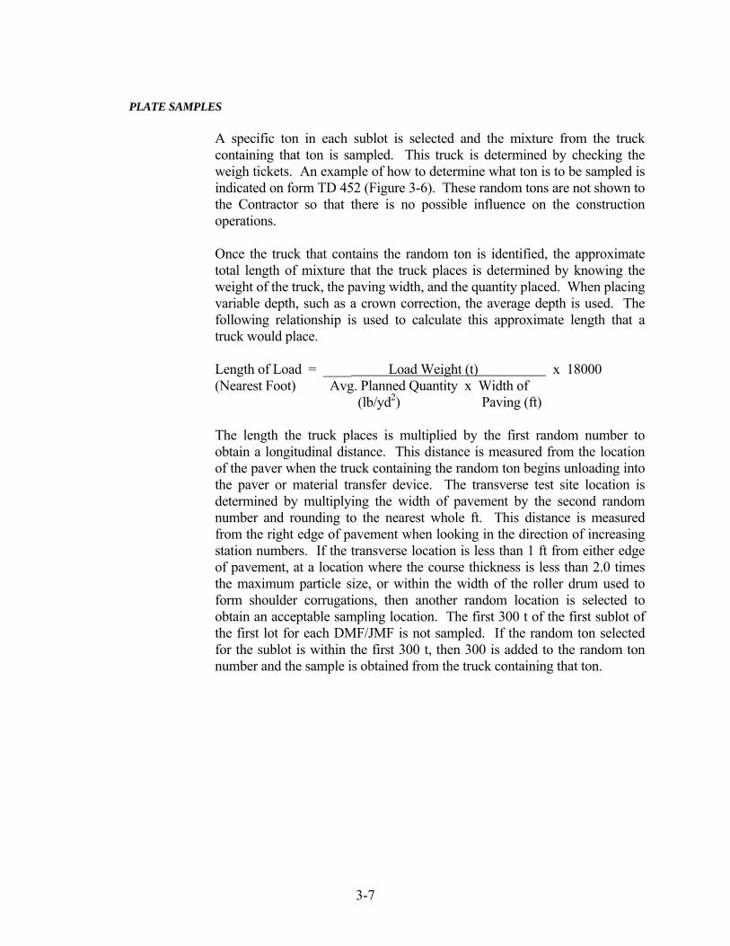
3-7
PLATE SAMPLES
A specific ton in each sublot is selected and the mixture from the truck containing that ton is sampled. This truck is determined by checking the weigh tickets. An example of how to determine what ton is to be sampled is indicated on form TD 452 (Figure 3-6). These random tons are not shown to the Contractor so that there is no possible influence on the construction operations. Once the truck that contains the random ton is identified, the approximate total length of mixture that the truck places is determined by knowing the weight of the truck, the paving width, and the quantity placed. When placing variable depth, such as a crown correction, the average depth is used. The following relationship is used to calculate this approximate length that a truck would place.
Length of Load = ____ Load Weight (t) x 18000 (Nearest Foot) Avg. Planned Quantity x Width of (lb/yd2) Paving (ft) The length the truck places is multiplied by the first random number to obtain a longitudinal distance. This distance is measured from the location of the paver when the truck containing the random ton begins unloading into the paver or material transfer device. The transverse test site location is determined by multiplying the width of pavement by the second random number and rounding to the nearest whole ft. This distance is measured from the right edge of pavement when looking in the direction of increasing station numbers. If the transverse location is less than 1 ft from either edge of pavement, at a location where the course thickness is less than 2.0 times the maximum particle size, or within the width of the roller drum used to form shoulder corrugations, then another random location is selected to obtain an acceptable sampling location. The first 300 t of the first sublot of the first lot for each DMF/JMF is not sampled. If the random ton selected for the sublot is within the first 300 t, then 300 is added to the random ton number and the sample is obtained from the truck containing that ton.

3-8
Figure 3-6. Random Sampling for Mix

3-9
The following example indicates how these random locations are determined. Example: Width of Pavement = 12 ft Load Weight = 20 t Mixture = 9.5 mm Surface Planned Quantity = 110 lb/yd2 Ending Station of Paver
of Previous Load = 158+00 Random Numbers = 256, .561 Test Site Station Length of Load = 20 x 18000 = 273 ft
110 x 12
Longitudinal Distance = 273 x .256 = 70 ft Random Station = (158+00) + 70 = 158+70 Transverse Distance
Distance = 12 x .561 = 6.7 ft (say 7 ft)
For contracts controlled by volumetrics for QC/QA HMA (401), several samples are required. The first plate sample location is determined by the random sampling procedure and this material is used for the maximum specific gravity and binder content samples. A second plate sample is placed longitudinally 2 ft upstation from the first plate at the same transverse offset. This sample is used for the gyratory specimens.
If an appeal by the Producer of the INDOT test results is accepted, backup samples are tested. These samples are obtained at the same time as the acceptance samples. The backup sample plate for the maximum specific gravity and binder content is placed transversely 2 ft from the first plate towards the center of the mat. The backup sample for the gyratory specimens is placed transversely 2 ft from the second plate towards the center of the mat.

3-10
The following diagram indicates an example of an arrangement of the plate samples when additional samples are required for QC/QA HMA:
An example of determining the sample locations is as follows:
Example: Width of Pavement = 12 ft Load Weight = 20 t Mixture = 9.5 mm Surface Planned Quantity = 110 lb/yd2 Ending Station of Paver of Previous Load = 158+00 Random Numbers = 256, .561
Test Site Station
Length of Load = 20 x 18000 = 273 ft
110 x 12
Longitudinal Distance = 273 x .256 = 70 ft Random Station = (158+00) + 70 = 158+70
Transverse Distance
Distance = 12 x .561 = 6.7 ft (say 7 ft)
Increasing Station
2 ft (0.6 m) 2 ft
(0.6 m)
Sample for Gyratory Specimens
Random Location MSG and Binder Content Sample
Backup Sample for Gyratory Specimens
Backup Sample for MSG and Binder Content

3-11
MSG and Binder Content Sample Random Location = 158 + 70 Transverse Distance = 7 ft Gyratory Specimens Sample Random Location = (158 + 70) + 02 = 158 + 72 Transverse Location = 7 ft Backup Sample for MSG and Binder Content Random Location = 158 + 70 Transverse Distance = 7-2 = 5 ft Backup Sample for Gyratory Specimens Random Location = (158 + 70) + 2 = 158 + 72 Transverse Distance = 7-2 = 5 ft
The procedure for obtaining plate samples (Figure 3-7) once the random location is determined is as follows:
1) A clean metal plate with attached wire is placed on the pavement. Should conditions on the contract require stabilizing movement to avoid slipping of the plate, a nail is driven into the pavement, and the plate hole placed onto the nail. A No. 18 gage mechanics wire and masonry nail has been proven to be effective for this purpose.
2) The wire is extended beyond the edge of the paving width.
The wire should not pass under a grade leveler attached to the paver. Trucks, pavers, or material transfer devices are allowed to cross the plate and/or wire. If a windrow elevator is used, the paving operation is stopped so that the plate may be placed between the windrow elevator and the paver.
3) After the mixture is placed and before any compaction from
the rollers occurs, the wire is used to locate the plate.

3-12
4) The plate is lifted with the wire, a narrow shovel or pitchfork is inserted under the plate, and the plate is lifted from the pavement.
5) The sample is then placed in a container for transport to the
testing facility. Material remaining on the plate is required to be removed and replaced into the sample container.
Figure 3-7. Plate Sampling
If the depth of the mixture is such that the material may fall off the sides of the plate when lifted from the pavement, a mold may be used with the plate. Only the plate or the plate with a mold procedures are allowed for the acceptance sample. The placement and location of the plate are done using the same procedures and restrictions used for sampling when only a plate is used. Additional requirements for using a mold with a plate include:
1) A clean round mold, with a height greater than the mixture thickness and diameter less than the width of the plate, is pushed by means of a circular motion into the mixture directly over the plate.

3-13
2) The mold and plate are raised together and a pitchfork or
narrow shovel is inserted under the plate. 3) The mold and plate are lifted from the pavement and any
excess mixture on top of the plate and outside of the mold is discarded.
4) The sample inside the mold is placed into the sample
container. Material remaining on the plate is removed and placed into the sample container.
When the pavement width is 4 ft or less, the samples are obtained from the center of the course and at least 1 ft from the edge of the course. The backup sample plate for the maximum specific gravity and binder content is placed 2 ft back station from the first plate in the center of the course. The backup sample for the gyratory specimens is placed 2 ft ahead station from the second plate in the center of the course. The following diagram indicates an example of an arrangement of the plate samples when additional samples are required for QC/QA HMA and the width of the pavement course is 4ft or less:
Increasing Station
2 ft (0.6 m)
Random Location MSG and Binder Content Sample
Backup Sample for MSG and Binder Content
Sample for Gyratory Specimens
Backup Sample for Gyratory Specimens
2 ft (0.6 m)
2 ft (0.6 m)

3-14
Example: Width of Pavement = 4 ft Load Weight = 20 t Mixture = 9.5 mm Surface Planned Quantity = 110 lb/yd2 Ending Station of Paver of Previous Load = 158+00 Random Numbers = .256, .561
Test Site Station Length of Load = 20 x 18000 = 818 ft
110 x 4 Longitudinal Distance = 818 x .256 = 209 ft Random Station = (158+00) + 209 = 160+09
Transverse Distance Distance = 4/2 = 2 ft
MSG and Binder Content Sample Random Location = 160 + 09 Transverse Distance = 2 ft Gyratory Specimens Sample Random Location = (160 + 09) + 2 ft = 160 + 11 Transverse Distance = 2 ft Backup Sample for MSG and Binder Content Random Location = (160 + 09) – 02 = 160 + 07 Transverse Distance = 2 ft Backup Sample for Gyratory Specimens Random Location = (160 + 11) + 2 ft = 160 + 13 Transverse Distance = 2 ft
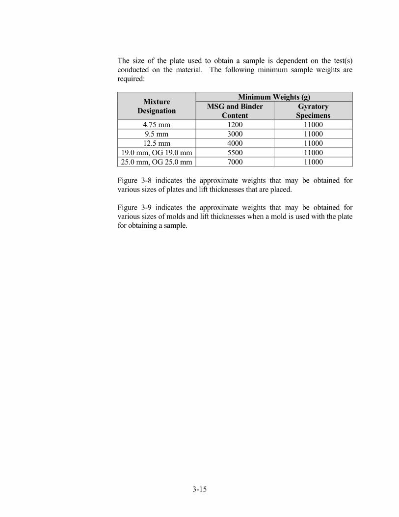
3-15
The size of the plate used to obtain a sample is dependent on the test(s) conducted on the material. The following minimum sample weights are required:
Mixture Designation
Minimum Weights (g) MSG and Binder
Content Gyratory Specimens
4.75 mm 1200 11000 9.5 mm 3000 11000 12.5 mm 4000 11000
19.0 mm, OG 19.0 mm 5500 11000 25.0 mm, OG 25.0 mm 7000 11000
Figure 3-8 indicates the approximate weights that may be obtained for various sizes of plates and lift thicknesses that are placed. Figure 3-9 indicates the approximate weights that may be obtained for various sizes of molds and lift thicknesses when a mold is used with the plate for obtaining a sample.

3-16
Approximate Sample Yield for Various Lift Thickness and Plate Sizes Lift
Thickness (inches)
Lay Rate
(lb/syd)
Plate Size, inches
8 9 10 11 12 14 16
Sample Weight (g) 1.25 137.5 3100 3900 4800 5900 7000 9500 12400
1.5 165 3700 4700 5800 7000 8400 11400 14900
1.75 192.5 4300 5500 6800 8200 9800 13300 17300
2.0 220 5000 6300 7700 9400 11100 15200 19800
2.25 247.5 5600 7100 8700 10500 12500 17100 22300
2.5 275 6200 7800 9700 11700 13900 19000 27800
2.75 302.5 6800 8600 10600 12900 15300 20900 27300
3.0 330 7400 9400 11600 14100 16700 22800 29700
3.25 357.5 8100 10200 12600 15200 18100 24700 32200
3.5 385 8700 11000 13500 16400 19500 26600 34700
3.75 412.5 9300 11800 14500 17600 20900 28500 37200
4.0 440 9900 12500 15500 18700 22300 30300 39600
4.25 467.5 10500 13300 16400 19800 23600 32100 41900
4.5 495 11100 14000 17300 21000 25000 34000 44400
4.75 522.5 11700 14800 18300 22100 26400 35900 46900
5.0 550 12300 15600 19300 23300 27700 37800 49300
5.25 577.5 12900 16400 20200 24500 29100 39700 51800
5.5 605 13600 17200 21200 25600 30500 41500 54300
5.75 632.5 14200 17900 22200 26800 31900 43400 56700
6.0 660 14800 18700 23100 28000 33300 45300 59200
Figure 3-8. Approximate Sample Yield for Various Lift Thickness and Plate Sizes

3-17
Approximate Sample Yield for Various Lift Thicknesses and Mold Sizes Lift
Thickness (inches)
Lay Rate (lb/yd²)
Mold Size, inches
8 10 12 14 16
Sample Weight (g) 1.25 137.5 2400 3800 5400 7400 9700
1.5 165 2900 4500 6500 8900 11600
1.75 192.5 3400 5300 7600 10400 13600
2.0 220 3900 6100 8700 11900 15500
2.25 247.5 4400 6800 9800 13300 17400
2.5 275 4800 7600 10900 14800 19400
2.75 302.5 5300 8300 12000 16300 21300
3.0 330 5800 9100 13100 17800 23200
3.25 357.5 6300 9800 14200 19300 25200
3.5 385 6800 10600 15300 20800 27100
3.75 412.5 7300 11300 16300 22200 29100
4.0 440 7700 12100 17400 23700 31000
4.25 467.5 8200 12900 18500 25200 32900
4.5 495 8700 13600 19600 26700 34900
4.75 522.5 9200 14400 20700 28200 36800
5.0 550 9700 15100 21800 29700 38700
5.25 577.5 10200 15900 22900 31100 40700
5.5 605 10700 16600 24000 32600 42600
5.75 632.5 11100 17400 25100 34100 44500
6.0 660 11600 18200 26100 35600 46500
Figure 3-9. Approximate Sample Yield for Various Lift Thicknesses and Mold Sizes

3-18
TRUCK SAMPLING
Truck sampling is conducted at the HMA Plant by taking a sample directly from a truck hauling the mixture to the contract. The random ton is determined in accordance with ITM 802. The truck containing that ton is then sampled. Generally, truck sampling is done by the Producer for Quality Control purposes. Truck sampling is conducted in accordance with ITM 580.
CORE SAMPLING
Core sampling (Figure 3-10) is done by the Conractor under the supervision of an INDOT Technician. For QC/QA HMA, two cores are obtained in each sublot for density of the mixture. The core locations are determined by ITM 802 with each core located independently within the sublot. All core sampling is done in accordance with ITM 580. A 6 in diameter core is obtained from the pavement. The sample is removed from the pavement with a device that does not damage the layer to be tested. The layer to be tested is marked with a lumber crayon or permanent marker.
Figure 3-10. HMA Coring
3-19
ADJUSTMENT PERIOD -- QC/QA HMA
The Producer is allowed an adjustment period for each mix design in which the mix design is verified and changes may be made in the DMF, if necessary. A job mix formula (JMF) is submitted for approval to the Engineer one working day after the Producer receives the test results for the binder content, VMA, and air content. The adjustment period is from the beginning of production and extending until 5000 t of base or intermediate QC/QA HMA, or 3000 t of surface QC/QA HMA has been produced for each mix design. A reduced adjustment period is allowed. If production extends into the next construction season, another adjustment period is allowed.
MIXTURE ACCEPTANCE QC/QA HMA
Acceptance of QC/QA HMA mixtures in accordance with 401 for binder content, VMA at Ndes, and air voids at Ndes for each lot is based on tests conducted by INDOT. INDOT randomly selects the location(s) within each sublot for sampling in accordance with the ITM 802. Samples from the pavement are obtained from each sublot in accordance with ITM 580.
A binder draindown test in accordance with AASHTO T 305 for open graded mixtures is required once per lot and may not exceed 0.50 %.
The acceptance test results for each sublot are available after the sublot and the testing are complete.
HMA
Acceptance of HMA mixtures in accordance with 402 is done on the basis of a Type D certification submitted by the Producer to the Project Engineer on a contract. An example of this form is shown in Figure 3-11. The certification is required to be submitted with the first truck of each type of mixture each day. If no test results are available, the Producer indicates on the form that test results are required to be obtained within the first 250 tons and each subsequent 1000 tons for base and intermediate mixtures, and the first 250 tons and each subsequent 600 tons for surface mixtures. A DMF developed for a QC/QA HMA mixture in accordance with 401 may be used for 402 mixtures and the source or grade of the binder may be changed; however, the high temperature grade of the binder is required to be in accordance with 402.

3-20
Mixtures in 402 that require the Type D Certification include miscellaneous HMA mixtures such as patching, widening, rumble strips, wedge and leveling, approaches, temporary mixtures, etc. In general these mixtures have low quantities and are placed in locations that plate samples cannot be obtained and the random sampling procedures are not applicable. On low traffic volume projects, mainline mixtures may also be included as mixtures accepted by Type D Certifications.

3-21
INDIANA DEPARTMENT OF TRANSPORTATION HOT MIX ASPHALT (HMA) CERTIFICATION
CONTRACT NUMBER ____RS-30000_________ DATE__5/3/07______ CERTIFIED HMA PRODUCER ______J. Wooden Construction___________________________ CERTIFIED HMA PLANT NUMBER ____3550___ DMF/JMF NUMBER ___0310075___ PG BINDER SOURCE _____7199_____ PG BINDER GRADE ____PG 64-22_____________ MIXTURE TYPE AND SIZE ______HMA Surface, 9.5 mm, Type A_______________________ DESIGN ESAL _____200,000_______ Air Voids __4.0__ (from DMF/JMF) Binder Content ___5.5__ (from DMF/JMF) This is to certify that the test results for Air Voids and Binder Content represent the HMA mixture supplied to this contract. Air Voids __4.3_ (± 1.5 % from DMF/JMF) Binder Content __5.7_ (± 0.7 % from DMF/JMF) * [ ] Test results are not available for submittal. A production sample shall be taken within the
first 250 t (250 Mg) and each subsequent 1000 t (1000 Mg) for base and intermediate mixtures and each subsequent 600 t (600 Mg) for surface mixtures.
* If Applicable __________________________________________ Signature of HMA Producer Official __________________________________________ Title of Official FOR PE/PS USE ONLY PAY ITEM(S) _____________________________ BASIS FOR USE NO. C999998 SPECIFICATION REFERENCE __ 304.04 - Patching __ 402.07(c) - Temporary HMA __ 610.02 - Approaches __ 304.05 - Widening __ 503.03(e) - Terminal Joints __ 611.02 - Crossovers __ 402.04 - HMA Pavements __ 507.05(b) - Partial Depth Patching __ 718.04 - Underdrains __ 402.07(a) - Rumble Strips __ 604.07(c) – Sidewalk __ 801.11- Temp. Cross __ 402.07(b) - Wedge & Leveling __ 605.07(c) - Curbing
Figure 3-11. HMA Certification

3-22
PAY FACTORS – QC/QA HMA (Dense Graded ≥ 1 Lot)
Pay factors for dense graded QC/QA HMA mixtures with original pay item quantities greater than or equal to one lot are determined in accordance with the procedures for Percent Within Limits (PWL) designated in ITM 588. The PWL method uses the average and standard deviation of the lot tests to estimate the percentage of the lot that is within the specification limits. The procedure for determining the PWL of the lot is as follows:
PWL - Mixture
1. Determine the average of the lot mixture properties for binder
content, air voids at Ndes, and VMA at Ndes as follows:
where:
x = average of the lot mixture property values xi = sublot mixture property value n = number of mixture sublot samples in the lot
The binder content, air voids,, and VMA lot average values are reported to the nearest 0.01 %.
2. Determine the standard deviation of the lot mixture property as
follows:
where:
s = standard deviation of the lot mixture property xi = sublot mixture property value x = average of the lot mixture property values n = number of mixture sublot samples in the lot
The standard deviation values for binder content, air voids, and VMA are reported to the nearest 0.01.
nx = x i
n
1=i∑
1n-
)x - x( = s
2i
n
1i∑=

3-23
3. Calculate the Upper Quality Index for each mixture property by subtracting the lot average of each mixture property from the Upper Specification Limit (Figure 3-12) and dividing the result by the standard deviation of the lot mixture property as follows:
where:
Qu = Upper Quality Index USL = Upper Specification Limit x = average of the lot mixture property values s = standard deviation of the lot mixture property
The binder content, air voids, and VMA Upper Quality Index values are reported to the nearest 0.01
Figure 3-12. Specification Limits
SPECIFICATION LIMITS Mixture
LSL* USL** Binder Content, % - 0.40 from JMF + 0.40 from JMF Air Voids(Va) at
Ndes, % 2.60 5.40
VMA at Ndes, % Greater Of Lesser Of Spec-0.50 JMF-1.20 Spec+2.00 JMF+1.20
Density LSL USL
Roadway Core Density
(%Gmm), % 91.00 Not Applicable
* LSL, Lower Specification Limit ** USL, Upper Specification Limit
sx - = QU
USL

3-24
4. Calculate the Lower Quality Index for each mixture property by subtracting the Lower Specification Limit (Figure 3-12) from the lot average of each mixture property and dividing the result by the standard deviation of the lot mixture property as follows:
where: QL = Lower Quality Index LSL = Lower Specification Limit x = average of the lot mixture property values s = standard deviation of the lot mixture property
The binder content, air voids, and VMA Lower Quality Index values are reported to the nearest 0.01
5. Determine the percentage of material that will fall within the
Upper and Lower Specification Limits (Figure 3-12) by entering the table of Quality Index Values (Figure 3-13) with QU or QL using the column appropriate to the total number of measurements, n.
6. Determine the percent of material that will fall within the limits for
each mixture property by adding the percent within the Upper Specification Limit (PWLU) to the percent within the Lower Specification Limit (PWLL), and subtracting 100 from the total as follows:
Total PWL = (PWLU + PWLL) – 100
PWL - Density
1. Determine the average of the lot density values as follows:
where: x = average of the lot density values xi = core density value n = number of cores in the lot
The density (% Gmm) lot average value is reported to the nearest 0.01 %.
s- x = QL
LSL
nx = x i
n
1=i∑

3-25
2. Determine the standard deviation of the lot density as follows:
where: s = standard deviation of the density of the lot x = average of the lot density values xi = core density value n = number of cores in the lot
The standard deviation value is reported to the nearest 0.01.
3. Calculate the Lower Quality Index for in-place density (% Gmm) by
subtracting the Lower Specification Limit (Figure 3-12) from the average of the density of the lot and dividing the result by the standard deviation of the density of the lot as follows:
where:
QL = Lower Quality Index LSL = Lower Specification Limit x = average of the lot density values s = standard deviation of the density of the lot
The density Lower Quality Index value is reported to the nearest 0.01.
4. Determine the PWL for density by entering the table of Quality
Index Values (Figure 3-13) using the column appropriate to the total number of measurements, n.
5. Determine the percent within the lower specification limit (PWLL)
for density as follows: Total PWL = PWLL
1n-
)x - x( = s
2i
1∑=
n
i
s- x = QL
LSL
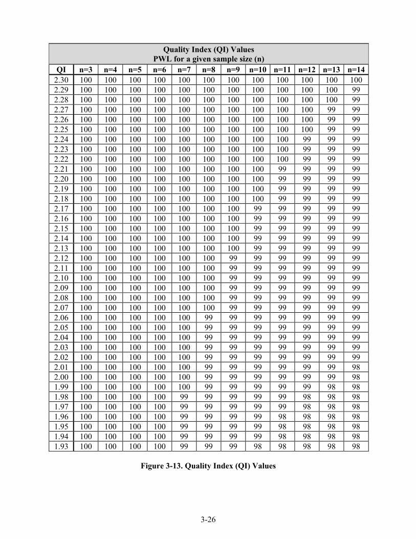
3-26
Quality Index (QI) Values PWL for a given sample size (n)
QI n=3 n=4 n=5 n=6 n=7 n=8 n=9 n=10 n=11 n=12 n=13 n=142.30 100 100 100 100 100 100 100 100 100 100 100 100 2.29 100 100 100 100 100 100 100 100 100 100 100 99 2.28 100 100 100 100 100 100 100 100 100 100 100 99 2.27 100 100 100 100 100 100 100 100 100 100 99 99 2.26 100 100 100 100 100 100 100 100 100 100 99 99 2.25 100 100 100 100 100 100 100 100 100 100 99 99 2.24 100 100 100 100 100 100 100 100 100 99 99 99 2.23 100 100 100 100 100 100 100 100 100 99 99 99 2.22 100 100 100 100 100 100 100 100 100 99 99 99 2.21 100 100 100 100 100 100 100 100 99 99 99 99 2.20 100 100 100 100 100 100 100 100 99 99 99 99 2.19 100 100 100 100 100 100 100 100 99 99 99 99 2.18 100 100 100 100 100 100 100 100 99 99 99 99 2.17 100 100 100 100 100 100 100 99 99 99 99 99 2.16 100 100 100 100 100 100 100 99 99 99 99 99 2.15 100 100 100 100 100 100 100 99 99 99 99 99 2.14 100 100 100 100 100 100 100 99 99 99 99 99 2.13 100 100 100 100 100 100 100 99 99 99 99 99 2.12 100 100 100 100 100 100 99 99 99 99 99 99 2.11 100 100 100 100 100 100 99 99 99 99 99 99 2.10 100 100 100 100 100 100 99 99 99 99 99 99 2.09 100 100 100 100 100 100 99 99 99 99 99 99 2.08 100 100 100 100 100 100 99 99 99 99 99 99 2.07 100 100 100 100 100 100 99 99 99 99 99 99 2.06 100 100 100 100 100 99 99 99 99 99 99 99 2.05 100 100 100 100 100 99 99 99 99 99 99 99 2.04 100 100 100 100 100 99 99 99 99 99 99 99 2.03 100 100 100 100 100 99 99 99 99 99 99 99 2.02 100 100 100 100 100 99 99 99 99 99 99 99 2.01 100 100 100 100 100 99 99 99 99 99 99 98 2.00 100 100 100 100 100 99 99 99 99 99 99 98 1.99 100 100 100 100 100 99 99 99 99 99 98 98 1.98 100 100 100 100 99 99 99 99 99 98 98 98 1.97 100 100 100 100 99 99 99 99 99 98 98 98 1.96 100 100 100 100 99 99 99 99 98 98 98 98 1.95 100 100 100 100 99 99 99 99 98 98 98 98 1.94 100 100 100 100 99 99 99 99 98 98 98 98 1.93 100 100 100 100 99 99 99 98 98 98 98 98
Figure 3-13. Quality Index (QI) Values

3-27
Quality Index (QI) Values PWL for a given sample size (n)
1.92 100 100 100 100 99 99 99 98 98 98 98 98 1.91 100 100 100 100 99 99 99 98 98 98 98 98 1.90 100 100 100 100 99 99 98 98 98 98 98 98 1.89 100 100 100 100 99 99 98 98 98 98 98 98 1.88 100 100 100 100 99 99 98 98 98 98 98 98 1.87 100 100 100 99 99 98 98 98 98 98 98 98 1.86 100 100 100 99 99 98 98 98 98 98 98 98 1.85 100 100 100 99 99 98 98 98 98 98 98 98 1.84 100 100 100 99 99 98 98 98 98 98 97 97 1.83 100 100 100 99 99 98 98 98 98 98 97 97 1.82 100 100 100 99 99 98 98 98 98 97 97 97 1.81 100 100 100 99 98 98 98 98 97 97 97 97 1.80 100 100 100 99 98 98 98 98 97 97 97 97 1.79 100 100 100 99 98 98 98 97 97 97 97 97 1.78 100 100 100 99 98 98 98 97 97 97 97 97 1.77 100 100 100 99 98 98 97 97 97 97 97 97 1.76 100 100 100 99 98 98 97 97 97 97 97 97 1.75 100 100 100 99 98 98 97 97 97 97 97 97 1.74 100 100 100 98 98 97 97 97 97 97 97 97 1.73 100 100 100 98 98 97 97 97 97 97 97 97 1.72 100 100 100 98 98 97 97 97 97 97 96 96 1.71 100 100 99 98 97 97 97 97 97 96 96 96 1.70 100 100 99 98 97 97 97 97 96 96 96 96 1.69 100 100 99 98 97 97 97 96 96 96 96 96 1.68 100 100 99 98 97 97 97 96 96 96 96 96 1.67 100 100 99 98 97 97 96 96 96 96 96 96 1.66 100 100 99 98 97 97 96 96 96 96 96 96 1.65 100 100 99 97 97 96 96 96 96 96 96 96 1.64 100 100 99 97 97 96 96 96 96 96 96 96 1.63 100 100 98 97 97 96 96 96 96 96 96 95 1.62 100 100 98 97 96 96 96 96 96 95 95 95 1.61 100 100 98 97 96 96 96 96 95 95 95 95 1.60 100 100 98 97 96 96 96 95 95 95 95 95 1.59 100 100 98 97 96 96 95 95 95 95 95 95 1.58 100 100 98 96 96 96 95 95 95 95 95 95 1.57 100 100 97 96 96 95 95 95 95 95 95 95 1.56 100 100 97 96 96 95 95 95 95 95 95 95 1.55 100 100 97 96 95 95 95 95 95 95 95 95
Quality Index Values (continued)

3-28
Quality Index (QI) Values PWL for a given sample size (n)
QI n=3 n=4 n=5 n=6 n=7 n=8 n=9 n=10 n=11 n=12 n=13 n=141.54 100 100 97 96 95 95 95 95 95 94 94 94 1.53 100 100 97 96 95 95 95 95 94 94 94 94 1.52 100 100 97 96 95 95 95 94 94 94 94 94 1.51 100 100 96 95 95 95 94 94 94 94 94 94 1.50 100 100 96 95 95 94 94 94 94 94 94 94 1.49 100 100 96 95 95 94 94 94 94 94 94 94 1.48 100 99 96 95 94 94 94 94 94 94 94 94 1.47 100 99 96 95 94 94 94 94 94 94 93 93 1.46 100 99 95 94 94 94 94 94 93 93 93 93 1.45 100 98 95 94 94 94 93 93 93 93 93 93 1.44 100 98 95 94 94 93 93 93 93 93 93 93 1.43 100 98 95 94 94 93 93 93 93 93 93 93 1.42 100 97 95 94 93 93 93 93 93 93 93 93 1.41 100 97 94 94 93 93 93 93 93 93 93 93 1.40 100 97 94 93 93 93 93 93 92 92 92 92 1.39 100 96 94 93 93 93 92 92 92 92 92 92 1.38 100 96 94 93 93 92 92 92 92 92 92 92 1.37 100 96 93 93 92 92 92 92 92 92 92 92 1.36 100 95 93 93 92 92 92 92 92 92 92 92 1.35 100 95 93 92 92 92 92 92 92 92 92 92 1.34 100 95 93 92 92 92 92 92 91 91 91 91 1.33 100 94 93 92 92 92 91 91 91 91 91 91 1.32 100 94 92 92 91 91 91 91 91 91 91 91 1.31 100 94 92 92 91 91 91 91 91 91 91 91 1.30 100 93 92 91 91 91 91 91 91 91 91 91 1.29 100 93 92 91 91 91 91 91 91 90 90 90 1.28 100 93 91 91 91 91 90 90 90 90 90 90 1.27 100 92 91 91 90 90 90 90 90 90 90 90 1.26 100 92 91 90 90 90 90 90 90 90 90 90 1.25 100 92 91 90 90 90 90 90 90 90 90 90 1.24 100 91 90 90 90 90 90 90 90 90 90 89 1.23 100 91 90 90 90 89 89 89 89 89 89 89 1.22 100 91 90 89 89 89 89 89 89 89 89 89 1.21 100 90 90 89 89 89 89 89 89 89 89 89 1.20 100 90 89 89 89 89 89 89 89 89 89 89 1.19 100 90 89 89 89 89 89 89 89 88 88 88 1.18 100 89 89 89 88 88 88 88 88 88 88 88 1.17 100 89 88 88 88 88 88 88 88 88 88 88
Quality Index Values (continued)
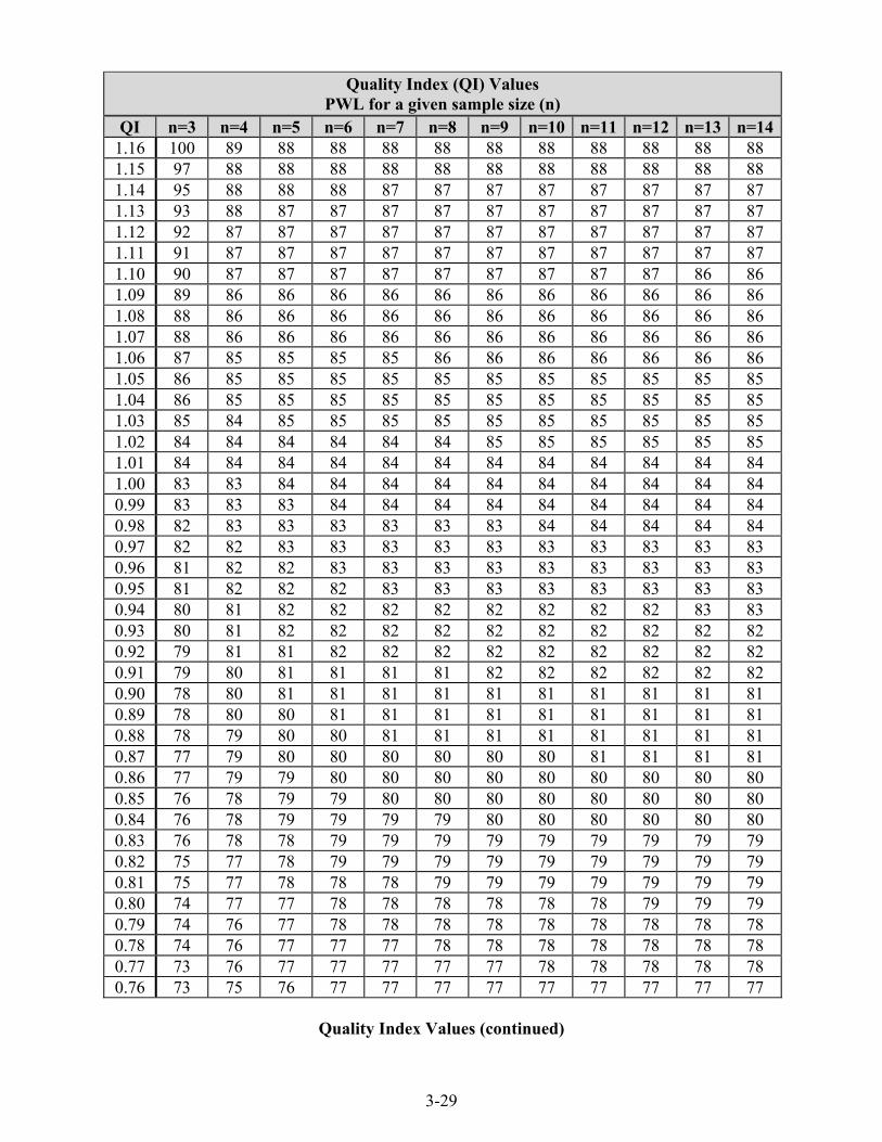
3-29
Quality Index (QI) Values PWL for a given sample size (n)
QI n=3 n=4 n=5 n=6 n=7 n=8 n=9 n=10 n=11 n=12 n=13 n=141.16 100 89 88 88 88 88 88 88 88 88 88 88 1.15 97 88 88 88 88 88 88 88 88 88 88 88 1.14 95 88 88 88 87 87 87 87 87 87 87 87 1.13 93 88 87 87 87 87 87 87 87 87 87 87 1.12 92 87 87 87 87 87 87 87 87 87 87 87 1.11 91 87 87 87 87 87 87 87 87 87 87 87 1.10 90 87 87 87 87 87 87 87 87 87 86 86 1.09 89 86 86 86 86 86 86 86 86 86 86 86 1.08 88 86 86 86 86 86 86 86 86 86 86 86 1.07 88 86 86 86 86 86 86 86 86 86 86 86 1.06 87 85 85 85 85 86 86 86 86 86 86 86 1.05 86 85 85 85 85 85 85 85 85 85 85 85 1.04 86 85 85 85 85 85 85 85 85 85 85 85 1.03 85 84 85 85 85 85 85 85 85 85 85 85 1.02 84 84 84 84 84 84 85 85 85 85 85 85 1.01 84 84 84 84 84 84 84 84 84 84 84 84 1.00 83 83 84 84 84 84 84 84 84 84 84 84 0.99 83 83 83 84 84 84 84 84 84 84 84 84 0.98 82 83 83 83 83 83 83 84 84 84 84 84 0.97 82 82 83 83 83 83 83 83 83 83 83 83 0.96 81 82 82 83 83 83 83 83 83 83 83 83 0.95 81 82 82 82 83 83 83 83 83 83 83 83 0.94 80 81 82 82 82 82 82 82 82 82 83 83 0.93 80 81 82 82 82 82 82 82 82 82 82 82 0.92 79 81 81 82 82 82 82 82 82 82 82 82 0.91 79 80 81 81 81 81 82 82 82 82 82 82 0.90 78 80 81 81 81 81 81 81 81 81 81 81 0.89 78 80 80 81 81 81 81 81 81 81 81 81 0.88 78 79 80 80 81 81 81 81 81 81 81 81 0.87 77 79 80 80 80 80 80 80 81 81 81 81 0.86 77 79 79 80 80 80 80 80 80 80 80 80 0.85 76 78 79 79 80 80 80 80 80 80 80 80 0.84 76 78 79 79 79 79 80 80 80 80 80 80 0.83 76 78 78 79 79 79 79 79 79 79 79 79 0.82 75 77 78 79 79 79 79 79 79 79 79 79 0.81 75 77 78 78 78 79 79 79 79 79 79 79 0.80 74 77 77 78 78 78 78 78 78 79 79 79 0.79 74 76 77 78 78 78 78 78 78 78 78 78 0.78 74 76 77 77 77 78 78 78 78 78 78 78 0.77 73 76 77 77 77 77 77 78 78 78 78 78 0.76 73 75 76 77 77 77 77 77 77 77 77 77
Quality Index Values (continued)
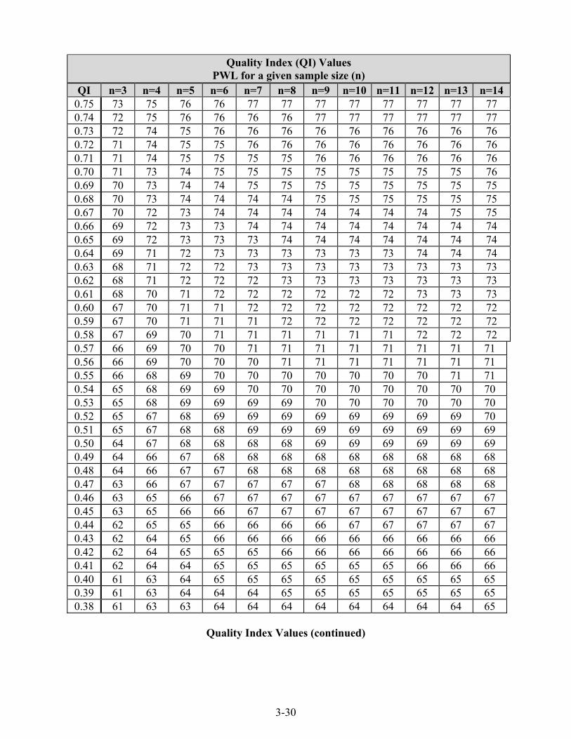
3-30
Quality Index (QI) Values PWL for a given sample size (n)
QI n=3 n=4 n=5 n=6 n=7 n=8 n=9 n=10 n=11 n=12 n=13 n=14 0.75 73 75 76 76 77 77 77 77 77 77 77 77 0.74 72 75 76 76 76 76 77 77 77 77 77 77 0.73 72 74 75 76 76 76 76 76 76 76 76 76 0.72 71 74 75 75 76 76 76 76 76 76 76 76 0.71 71 74 75 75 75 75 76 76 76 76 76 76 0.70 71 73 74 75 75 75 75 75 75 75 75 76 0.69 70 73 74 74 75 75 75 75 75 75 75 75 0.68 70 73 74 74 74 74 75 75 75 75 75 75 0.67 70 72 73 74 74 74 74 74 74 74 75 75 0.66 69 72 73 73 74 74 74 74 74 74 74 74 0.65 69 72 73 73 73 74 74 74 74 74 74 74 0.64 69 71 72 73 73 73 73 73 73 74 74 74 0.63 68 71 72 72 73 73 73 73 73 73 73 73 0.62 68 71 72 72 72 73 73 73 73 73 73 73 0.61 68 70 71 72 72 72 72 72 72 73 73 73 0.60 67 70 71 71 72 72 72 72 72 72 72 72 0.59 67 70 71 71 71 72 72 72 72 72 72 72 0.58 67 69 70 71 71 71 71 71 71 72 72 72 0.57 66 69 70 70 71 71 71 71 71 71 71 71 0.56 66 69 70 70 70 71 71 71 71 71 71 71 0.55 66 68 69 70 70 70 70 70 70 70 71 71 0.54 65 68 69 69 70 70 70 70 70 70 70 70 0.53 65 68 69 69 69 69 70 70 70 70 70 70 0.52 65 67 68 69 69 69 69 69 69 69 69 70 0.51 65 67 68 68 69 69 69 69 69 69 69 69 0.50 64 67 68 68 68 68 69 69 69 69 69 69 0.49 64 66 67 68 68 68 68 68 68 68 68 68 0.48 64 66 67 67 68 68 68 68 68 68 68 68 0.47 63 66 67 67 67 67 67 68 68 68 68 68 0.46 63 65 66 67 67 67 67 67 67 67 67 67 0.45 63 65 66 66 67 67 67 67 67 67 67 67 0.44 62 65 65 66 66 66 66 67 67 67 67 67 0.43 62 64 65 66 66 66 66 66 66 66 66 66 0.42 62 64 65 65 65 66 66 66 66 66 66 66 0.41 62 64 64 65 65 65 65 65 65 66 66 66 0.40 61 63 64 65 65 65 65 65 65 65 65 65 0.39 61 63 64 64 64 65 65 65 65 65 65 65 0.38 61 63 63 64 64 64 64 64 64 64 64 65
Quality Index Values (continued)
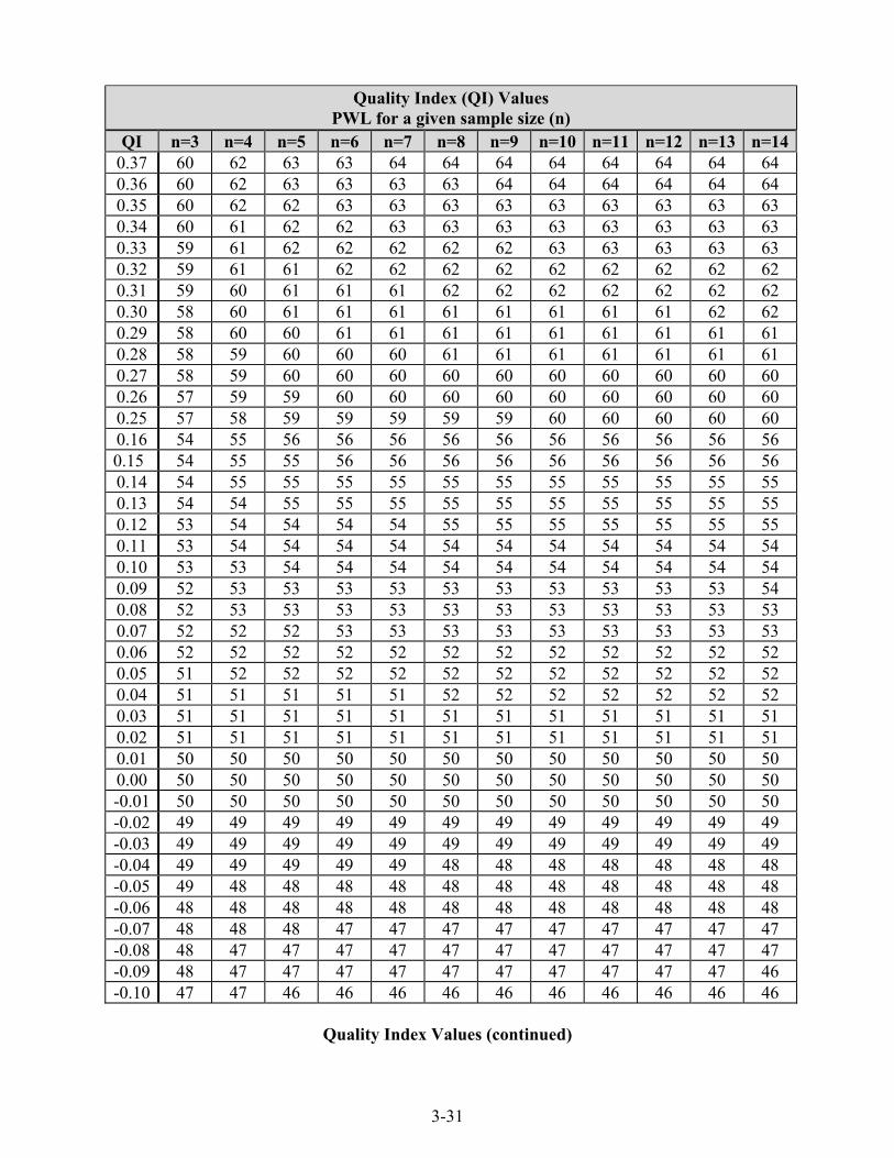
3-31
Quality Index (QI) Values PWL for a given sample size (n)
QI n=3 n=4 n=5 n=6 n=7 n=8 n=9 n=10 n=11 n=12 n=13 n=140.37 60 62 63 63 64 64 64 64 64 64 64 64 0.36 60 62 63 63 63 63 64 64 64 64 64 64 0.35 60 62 62 63 63 63 63 63 63 63 63 63 0.34 60 61 62 62 63 63 63 63 63 63 63 63 0.33 59 61 62 62 62 62 62 63 63 63 63 63 0.32 59 61 61 62 62 62 62 62 62 62 62 62 0.31 59 60 61 61 61 62 62 62 62 62 62 62 0.30 58 60 61 61 61 61 61 61 61 61 62 62 0.29 58 60 60 61 61 61 61 61 61 61 61 61 0.28 58 59 60 60 60 61 61 61 61 61 61 61 0.27 58 59 60 60 60 60 60 60 60 60 60 60 0.26 57 59 59 60 60 60 60 60 60 60 60 60 0.25 57 58 59 59 59 59 59 60 60 60 60 60 0.16 54 55 56 56 56 56 56 56 56 56 56 56 0.15 54 55 55 56 56 56 56 56 56 56 56 56 0.14 54 55 55 55 55 55 55 55 55 55 55 55 0.13 54 54 55 55 55 55 55 55 55 55 55 55 0.12 53 54 54 54 54 55 55 55 55 55 55 55 0.11 53 54 54 54 54 54 54 54 54 54 54 54 0.10 53 53 54 54 54 54 54 54 54 54 54 54 0.09 52 53 53 53 53 53 53 53 53 53 53 54 0.08 52 53 53 53 53 53 53 53 53 53 53 53 0.07 52 52 52 53 53 53 53 53 53 53 53 53 0.06 52 52 52 52 52 52 52 52 52 52 52 52 0.05 51 52 52 52 52 52 52 52 52 52 52 52 0.04 51 51 51 51 51 52 52 52 52 52 52 52 0.03 51 51 51 51 51 51 51 51 51 51 51 51 0.02 51 51 51 51 51 51 51 51 51 51 51 51 0.01 50 50 50 50 50 50 50 50 50 50 50 50 0.00 50 50 50 50 50 50 50 50 50 50 50 50 -0.01 50 50 50 50 50 50 50 50 50 50 50 50 -0.02 49 49 49 49 49 49 49 49 49 49 49 49 -0.03 49 49 49 49 49 49 49 49 49 49 49 49 -0.04 49 49 49 49 49 48 48 48 48 48 48 48 -0.05 49 48 48 48 48 48 48 48 48 48 48 48 -0.06 48 48 48 48 48 48 48 48 48 48 48 48 -0.07 48 48 48 47 47 47 47 47 47 47 47 47 -0.08 48 47 47 47 47 47 47 47 47 47 47 47 -0.09 48 47 47 47 47 47 47 47 47 47 47 46 -0.10 47 47 46 46 46 46 46 46 46 46 46 46
Quality Index Values (continued)

3-32
Quality Index (QI) Values PWL for a given sample size (n)
QI n=3 n=4 n=5 n=6 n=7 n=8 n=9 n=10 n=11 n=12 n=13 n=14-0.11 47 46 46 46 46 46 46 46 46 46 46 46 -0.12 47 46 46 46 46 45 45 45 45 45 45 45 -0.13 46 46 45 45 45 45 45 45 45 45 45 45 -0.14 46 45 45 45 45 45 45 45 45 45 45 45 -0.15 46 45 45 44 44 44 44 44 44 44 44 44 -0.16 46 45 44 44 44 44 44 44 44 44 44 44 -0.17 45 44 44 44 44 44 44 43 43 43 43 43 -0.18 45 44 44 43 43 43 43 43 43 43 43 43 -0.19 45 44 43 43 43 43 43 43 43 43 43 43 -0.20 44 43 43 43 43 42 42 42 42 42 42 42 -0.21 44 43 43 42 42 42 42 42 42 42 42 42 -0.22 44 43 42 42 42 42 42 42 42 42 42 -0.23 44 42 42 42 -0.24 43 42 -0.25 43 42 -0.26 43 -0.27 42 -0.28 42 -0.29 42 -0.30 42
Quality Index Values (continued)

3-33
Pay Factors
Pay factors (PF) are calculated for the binder content, air voids at Ndes, VMA at Ndes, and in-place density (% Gmm). The appropriate pay factor for each property is calculated as follows: Estimated PWL > 90
Pay Factor = (105.00 – 0.50 x (100.00 – PWL)/100 Estimated PWL ≥ 50 and ≤ 90
Pay Factor = (100.00 – 0.000020072 x (100.00 – PWL)3.5877)/100 Binder content, air voids, VMA, and in-place density PF values are reported to the nearest 0.01. If the Lot PWL for any one of the properties is less than 50 or a sublot has an air void content less than 1.0 %, the lot is referred to the Office of Materials Management as a failed material. A composite pay factor for each lot based on the mixture properties and density is determined by a weighted formula as follows: Lot Pay Factor = 0.20 (PFBINDER) + 0.35 (PFVOIDS) + 0.10 (PFVMA)
+ 0.35 (PFDENSITY) where: Lot PF = Lot Composite Pay Factor for Mixture and Density PFBINDER = Lot Pay Factor for Binder Content PFVOIDS = Lot Pay Factor for Air Vois at Ndes PF VMA = Lot Pay Factor for VMA at Ndes PFDENSITY = Lot Pay Factor for In-Place Density (%Gmm)
ADJUSTMENT QUANTITY -- QC/QA HMA ≥ 1 Lot
The pay factors are used to calculate a quality assurance adjustment quantity (q) for the lot. The adjustment for mixture properties and density is calculated as follows:
q = L x U x (Lot PF - 1.00)/MAF
where:
q = quality assurance adjustment for mixture properties and density of the lot
L = Lot quantity U = Unit price for the material, $/Ton
Lot PF = Lot Pay Factor

3-34
The following example indicates how the Pay Factors and the Qualiity Assurance Adjustment for PWL are determined for QC/QA mixtures ≥ 1 Lot: Example: 19.0 mm Intermediate Sublot 1 = 1000 tons Sublot 2 = 1000 tons Sublot 3 = 1000 tons Sublot 4 = 1000 tons
Sublot 5 = 1000 tons Unit Price = $40.00/ton MAF = 1.000 JMF % Binder = 5.0 % Air Voids = 4.0 % VMA = 13.5 % Sublot 1 Sublot 2 Sublot 3 Sublot 4 Sublot 5 % Binder 4.80 4.90 5.20 5.20 5.30 Air Voids 3.80 3.50 3.20 4.70 4.60 VMA 13.80 13.90 12.60 12.80 13.70 Density (%MSG) 91.10 91.70 92.30 92.90 92.50
% Binder
x = 4.80 + 4.90 + 5.20 + 5.20 + 5.30 = 5.08 5 s = 0.22 USL = + 0.40 from JMF = 0.40 + 5.0 = 5.40
From Figure 5-10 for n = 5 the PWLU is 95
45.122.0
08.540.5s
x - USL = QU =−
=

3-35
LSL = - 0.40 from JMF = 5.0 – 0.40 = 4.60
From Figure 3-13 for n = 5 the PWLL is 100
Total PWL = (PWLU + PWLL) – 100 = (95 + 100) – 100 = 95
Pay Factor (Estimated PWL > 90) = (105.00 – 0.50 x (100.00 – PWL)/100
= (105.00 – 0.50 x (100.00 – 95)/100
= (105.00 – 2.50)/100 = 1.03
Pay Factors for the Air Voids, VMA, and Density are indicated in Figure 3-14 and are as follows:
Pay Factor (Air Voids) = 1.05
Pay Factor (VMA) = 1.02
Paty Factor (Density) = 1.04
Lot Pay Factor = 0.20 (PFBINDER) + 0.35 (PFVOIDS) + 0.10 (PFVMA) + 0.35 (PFDENSITY)
= 0.20 (1.03) + 0.35 (1.05) + 0.10 (1.02) + 0.35 (1.04)
= 0.21 + 0.37 + 0.10 + 0.36 = 1.04
The Quality Assurance Adjustment for the Lot is calculated as follows:
Quality Assurance Adjustment ($) = L x U x (Lot PF – 1.00)/MAF
L = Lot quantity U = Unit Price for Material, $/Ton Lot PF = Lot Pay Factor
Quality Assurance Adjustment = 5000 x $40.00 x (1.04 – 1.00)/1.000
= + $8000.00
18.222.0
60.408.5sLSL- x = QL =
−=

3-36
INDIANA DEPARTMENT OF TRANSPORTATION HOT MIX ASPHALT ANALYSIS FOR QUALITY ASSURANCE
CONTRACT NO. _____________ PLANT NO. ___________ LOT NO. _______ DATE ____________
MIXTURE ___________________________________ DMF/JMF NO. ___________________________
Mixture &
Density x s
Qu QL
Total PWL USL
PWLU LSL
PWLL
% Binder 5.08 0.22 5.40 1.45 95 4.60 2.18 100 95
Air Voids 3.96 0.67 5.40 2.15 100 2.60 2.03 100 100
VMA 13.36 0.61 14.70 2.20 100 12.50 1.41 94 94
Density (% MSG) 92.10 0.71 91.00 1.55 97 97
* Requires submittal to the Office of Materials Management for Failed Material Investigation Binder Air Voids VMA Density Lot
Pay Factor
Quality Assurance Adjustment
Pay Factor 0.20xPF Pay
Factor 0.35xPF Pay Factor 0.10xPF Pay
Factor 0.35xPF
1.03 0.21 1.05 0.37 1.02 0.10 1.04 0.36 1.04 + $8000
Estimated PWL > 90
Pay Factor = (105.00 – 0.50 x (100.00 – PWL)/100
Estimated PWL ≥ 50 and ≤ 90
Pay Factor = (100.00 – 0.000020072 x (100.00 – PWL)3.5877)/100
Lot Pay Factor = 0.20 (PFBINDER) + 0.35 (PFVOIDS) + 0.10 (PFVMA) + 0.35 (PFDENSITY)
Quality Assurance Adjustment ($) = L x U x (Lot PF – 1.00)/MAF
L = Lot quantity U = Unit Price for Material, $/Ton Lot PF = Lot Pay Factor
Figure 3-14. Quality Assurance Adjustment
sx - USL = QU s
- x = QLLSL

3-37
PAY FACTORS -- QC/QA HMA (Dense Graded Mixture < 1 Lot and Open Graded
Mixtures)
After the tests are conducted, the test data is evaluated for compliance with the Specifications. CAA and temperature tests are taken in accordance with standard procedures and recorded. For open graded mixtures, lot numbers begin with number 1 for each type of mixture and are continuous for the entire contract regardless of the number of adjustment periods for that type of mixture.
When the required tests for one sublot are completed, the difference between the test values and the required value on the JMF is determined and pay factors calculated. For mixtures produced during the adjustment period, pay factors based on the JMF are used. A composite pay factor for each sublot is determined for the binder content, air voids @ Ndes, VMA @ Ndes, and density of the mixture as follows:
SCPF = 0.20(PFBINDER) + 0.35(PFVOIDS) + 0.10(PFVMA) + 0.35(PFDENSITY) where: SCPF = Sublot Composite Pay Factor for Mixture and Density PFBINDER = Sublot Pay Factor for Binder Content PFVOIDS = Sublot Pay Factor for Air Voids at Ndes PFVMA = Sublot Pay Factor for VMA at Ndes PFDENSITY = Sublot Pay Factor for Density
If the SCPF for a sublot is less than 0.85, the pavement is evaluated by INDOT. If the Contractor is not required to remove the mixture, quality assurance adjustments of the sublot are assessed or other corrective actions taken as determined by INDOT.

3-38
MIXTURE
Sublot test results for mixture properties are assigned pay factors in accordance with the following:
BINDER CONTENT
DENSE GRADED Deviation from JMF
(±%)
OPEN GRADED Deviation from JMF
(±%)
PAY FACTOR
≤ 0.2 ≤ 0.2 1.05 0.3 0.3 1.04 0.4 0.4 1.02 0.5 0.5 1.00 0.6 0.6 0.90 0.7 0.7 0.80 0.8 0.8 0.60 0.9 0.9 0.30 1.0 1.0 0.00
> 1.0 > 1.0 Submit to the Office of Materials
Management* * Test results are considered and adjudicated as a failed material in accordance with normal INDOT practice as listed in 105.03.
AIR VOIDS
DENSE GRADED Deviation from JMF
(±%)
OPEN GRADED Deviation from JMF
(±%)
PAY FACTOR
≤ 0.5 ≤ 1.0 1.05 > 0.5 and ≤ 1.0 > 1.0 and ≤ 3.0 1.00
1.1 3.1 0.98 1.2 3.2 0.96 1.3 3.3 0.94 1.4 3.4 0.92 1.5 3.5 0.90 1.6 3.6 0.84 1.7 3.7 0.78 1.8 3.8 0.72 1.9 3.9 0.66 2.0 4.0 0.60 > 2.0 > 4.0 Submit to the
Office of Materials Management*
* Test results are considered and adjudicated as a failed material in accordance with normal INDOT practice as listed in 105.03.
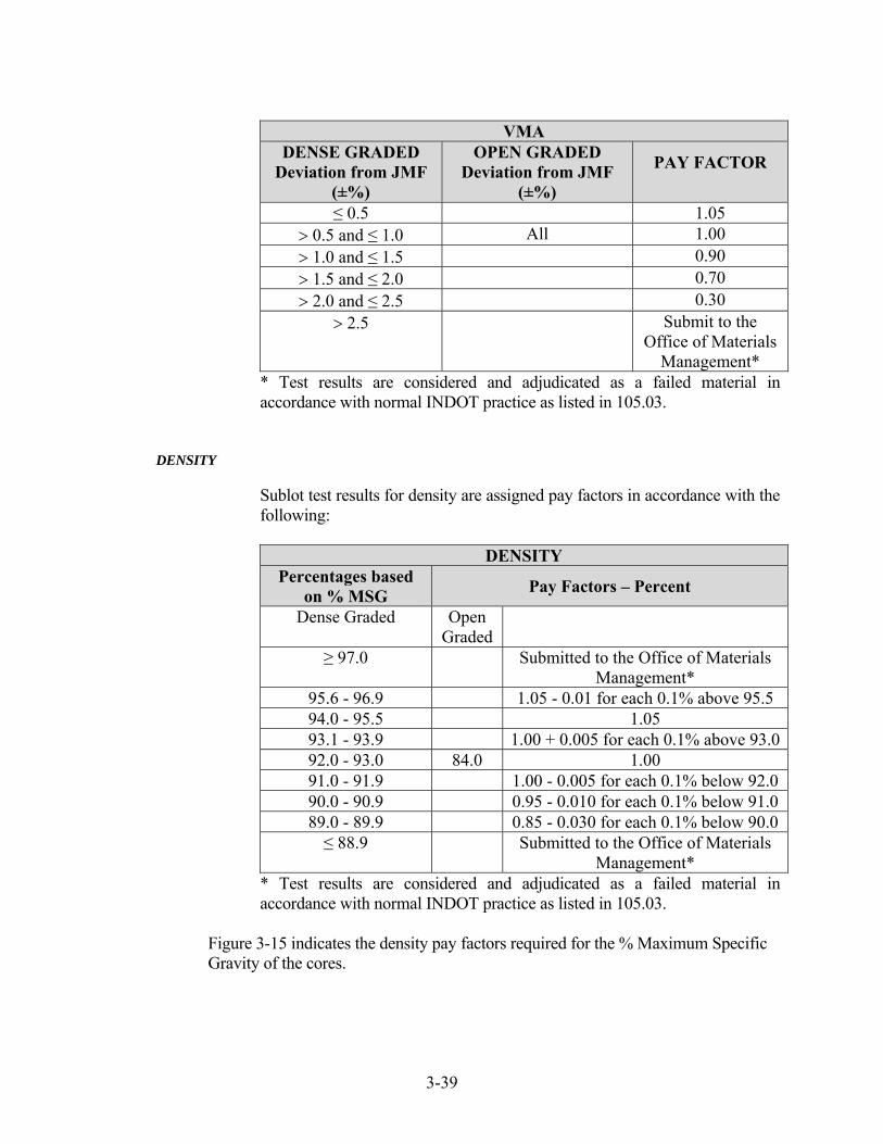
3-39
VMA
DENSE GRADED Deviation from JMF
(±%)
OPEN GRADED Deviation from JMF
(±%)
PAY FACTOR
≤ 0.5 1.05 > 0.5 and ≤ 1.0 All 1.00 > 1.0 and ≤ 1.5 0.90 > 1.5 and ≤ 2.0 0.70 > 2.0 and ≤ 2.5 0.30
> 2.5 Submit to the Office of Materials
Management* * Test results are considered and adjudicated as a failed material in accordance with normal INDOT practice as listed in 105.03.
DENSITY
Sublot test results for density are assigned pay factors in accordance with the following:
DENSITY Percentages based
on % MSG Pay Factors – Percent
Dense Graded Open Graded
≥ 97.0 Submitted to the Office of Materials Management*
95.6 - 96.9 1.05 - 0.01 for each 0.1% above 95.5 94.0 - 95.5 1.05 93.1 - 93.9 1.00 + 0.005 for each 0.1% above 93.092.0 - 93.0 84.0 1.00 91.0 - 91.9 1.00 - 0.005 for each 0.1% below 92.0 90.0 - 90.9 0.95 - 0.010 for each 0.1% below 91.0 89.0 - 89.9 0.85 - 0.030 for each 0.1% below 90.0 ≤ 88.9 Submitted to the Office of Materials
Management* * Test results are considered and adjudicated as a failed material in accordance with normal INDOT practice as listed in 105.03.
Figure 3-15 indicates the density pay factors required for the % Maximum Specific Gravity of the cores.

3-40
DENSITY -- DENSE GRADED
% MSG
Pay Factor
% MSG
Pay Factor
% MSG
Pay Factor
% MSG
Pay Factor
≥97.0 * 94.9 1.05 92.8 1.00 90.7 0.92
96.9 0.91 94.8 1.05 92.7 1.00 90.6 0.91
96.8 0.92 94.7 1.05 92.6 1.00 90.5 0.90
96.7 0.93 94.6 1.05 92.5 1.00 90.4 0.89
96.6 0.94 94.5 1.05 92.4 1.00 90.3 0.88
96.5 0.95 94.4 1.05 92.3 1.00 90.2 0.87
96.4 0.96 94.3 1.05 92.2 1.00 90.1 0.86
96.3 0.97 94.2 1.05 92.1 1.00 90.0 0.85
96.2 0.98 94.1 1.05 92.0 1.00 89.9 0.82
96.1 0.99 94.0 1.05 91.9 1.00 89.8 0.79
96.0 1.00 93.9 1.05 91.8 0.99 89.7 0.76
95.9 1.01 93.8 1.04 91.7 0.99 89.6 0.73
95.8 1.02 93.7 1.04 91.6 0.98 89.5 0.70
95.7 1.03 93.6 1.03 91.5 0.98 89.4 0.67
95.6 1.04 93.5 1.03 91.4 0.97 89.3 0.64
95.5 1.05 93.4 1.02 91.3 0.97 89.2 0.61
95.4 1.05 93.3 1.02 91.2 0.96 89.1 0.58
95.3 1.05 93.2 1.01 91.1 0.96 89.0 0.55
95.2 1.05 93.1 1.01 91.0 0.95 88.9 *
95.1 1.05 93.0 1.00 90.9 0.94
95.0 1.05 92.9 1.00 90.8 0.93
DENSITY -- OPEN GRADED 84.0 -- 1.00
* Requires submittal to Office of Materials Management for Failed Material Investigation
Figure 3-15. Density Pay Factors

3-41
ADJUSTMENT QUANTITY -- QC/QA HMA < 1 Lot and Open Graded Mixtures
The pay factors are used to calculate a quality assurance adjustment quantity (q) for the sublot. The adjustment for mixture properties and density is calculated as follows:
q = L x U x (SCPF - 1.00)/MAF
where:
q = quality assurance adjustment for the sublot L = Sublot quantity U = Unit price for the material, $/Ton
SCPF = Sublot composite pay factor
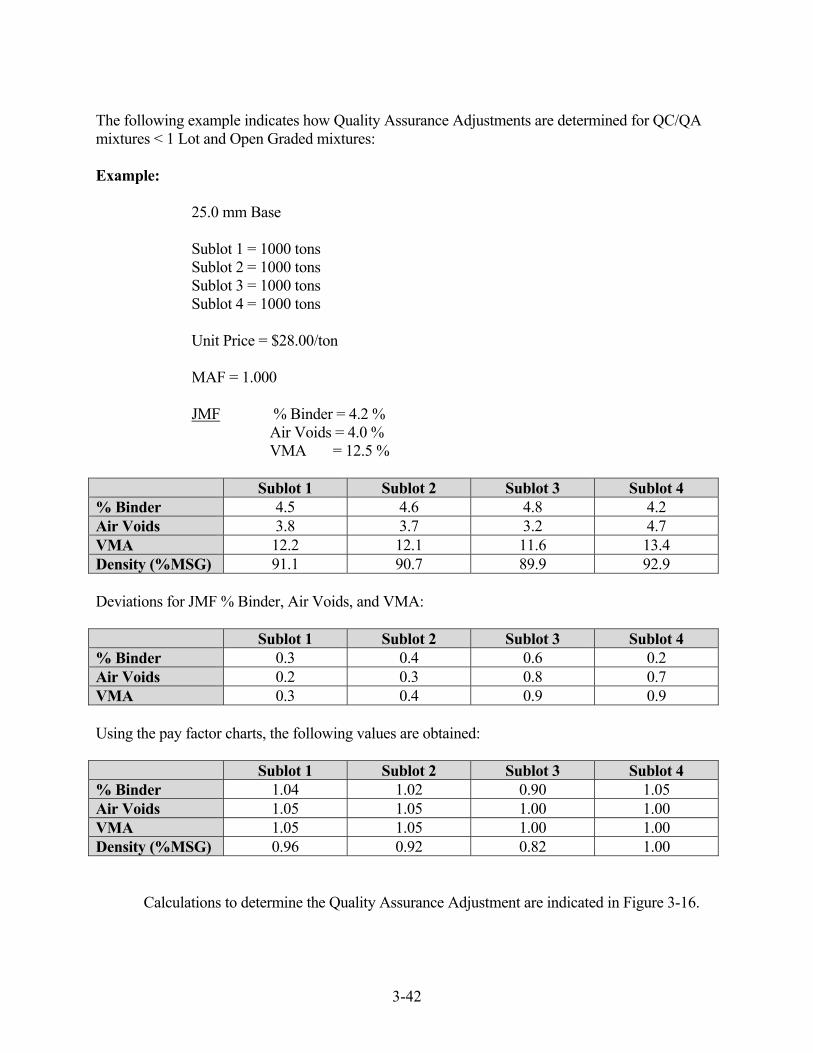
3-42
The following example indicates how Quality Assurance Adjustments are determined for QC/QA mixtures < 1 Lot and Open Graded mixtures: Example: 25.0 mm Base Sublot 1 = 1000 tons Sublot 2 = 1000 tons Sublot 3 = 1000 tons Sublot 4 = 1000 tons Unit Price = $28.00/ton MAF = 1.000 JMF % Binder = 4.2 % Air Voids = 4.0 % VMA = 12.5 % Sublot 1 Sublot 2 Sublot 3 Sublot 4 % Binder 4.5 4.6 4.8 4.2 Air Voids 3.8 3.7 3.2 4.7 VMA 12.2 12.1 11.6 13.4 Density (%MSG) 91.1 90.7 89.9 92.9 Deviations for JMF % Binder, Air Voids, and VMA: Sublot 1 Sublot 2 Sublot 3 Sublot 4 % Binder 0.3 0.4 0.6 0.2 Air Voids 0.2 0.3 0.8 0.7 VMA 0.3 0.4 0.9 0.9 Using the pay factor charts, the following values are obtained: Sublot 1 Sublot 2 Sublot 3 Sublot 4 % Binder 1.04 1.02 0.90 1.05 Air Voids 1.05 1.05 1.00 1.00 VMA 1.05 1.05 1.00 1.00 Density (%MSG) 0.96 0.92 0.82 1.00 Calculations to determine the Quality Assurance Adjustment are indicated in Figure 3-16.

3-43
INDIANA DEPARTMENT OF TRANSPORTATION HOT MIX ASPHALT ANALYSIS FOR QUALITY ASSURANCE
CONTRACT NO. _______________ PLANT NO. _________ LOT NO. __________ DATE ____________ MIXTURE _____________________________________________ DMF/JMF NO. ____________________ Mixture
& Density
SUBLOT 1 SUBLOT 2 SUBLOT 3 SUBLOT 4
Pay Factor
Mult
Pay Factor
Mult
Pay Factor
Mult.
Pay Factor
Mult.
% Binder
1.04
0.20
0.2080
1.02
0.20
0.2040
0.90
0.20
0.1800
1.05
0.20
0.2100
Air Voids
1.05
0.35
0.3675
1.05
0.35
0.3675
1.00
0.35
0.3500
1.00
0.35
0.3500
VMA
1.05
0.10
0.1050
1.05
0.10
0.1050
1.00
0.10
0.1000
1.00
0.10
0.1000
Density
0.96
0.35
0.3360
0.92
0.35
0.3220
0.82
0.35
0.2870
1.00
0.35
0.3500
SCPF
1.02
1.00
0.92
1.01
* Requires submittal to the Materials and Tests Division for Failed Material Investigation
QUALITY ASSURANCE ADJUSTMENTS
Sublot 1 Quantity
L (tons)
Sublot 1 Adjustment ($)
Sublot 2 Quantity
L (tons)
Sublot 2
Adjustment ($)
Sublot 3 Quantity
L (tons)
Sublot 3
Adjustment ($)
Sublot 4 Quantity L (tons)
Sublot 4 Adjustment ($)
1000
+560
1000
0
1000
-2240
1000
+280
U = Unit Price for Material, $/Ton Quality Assurance Adjustment = L x U x (SCPF – 1.00) / MAF
Figure 3-16. Quality Assurance Adjustment

3-44
MIX APPEAL -- QC/QA HMA
If the Producer does not agree with the acceptance test results, a request may be submitted in writing that additional samples be tested. The written request is required to include the Producer's test results and be made within seven calendar days of receipt of the written results of the HMA tests for that lot. The appeal is not accepted if the Producer has not conducted any tests that indicate a higher Pay Factor than was determined from the test results by INDOT.
Additional tests for the appeal may be requested for the maximum specific gravity, bulk specific gravity of the gyratory specimens, binder content, or bulk specific gravity of the density cores. One or more of these tests may be requested for the sublot or entire lot. Upon approval of the appeal, the backup samples are tested as follows:
1) Maximum Specific Gravity -- The sample is dried in
accordance with ITM 572 and mass determined in water in accordance with AASHTO T 209.
2) Bulk Specific Gravity of the Gyratory Specimens -- New
gyratory specimens are prepared and tested in accordance with AASHTO T 312.
3) Binder Content -- The binder content is tested in accordance
with the test method that was used for acceptance or as directed by INDOT.
4) Bulk Specific Gravity of the Density Core -- Additional cores
are taken within seven calendar days unless otherwise directed. The core locations are determined by adding 1.0 ft longitudinally of the cores tested for acceptance using the same transverse offset. The cores are dried in accordance with ITM 572 and tested in accordance with AASHTO T 166, Method A.
The appeal results replace all previous test result(s) for acceptance of the mixture properties and density.
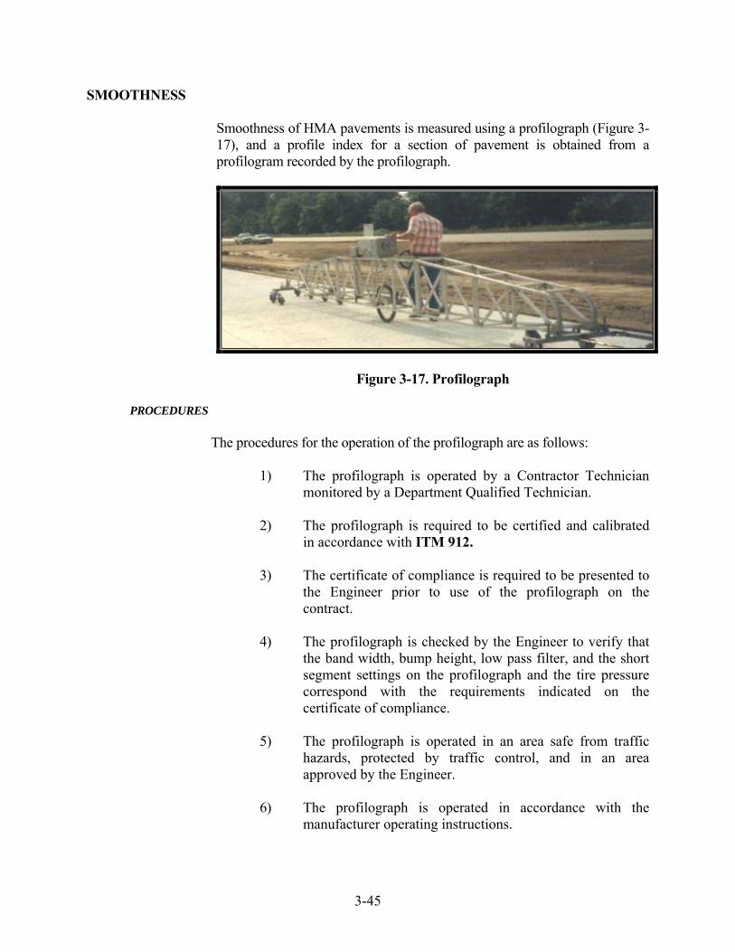
3-45
SMOOTHNESS
Smoothness of HMA pavements is measured using a profilograph (Figure 3-17), and a profile index for a section of pavement is obtained from a profilogram recorded by the profilograph.
Figure 3-17. Profilograph
PROCEDURES
The procedures for the operation of the profilograph are as follows:
1) The profilograph is operated by a Contractor Technician monitored by a Department Qualified Technician.
2) The profilograph is required to be certified and calibrated
in accordance with ITM 912.
3) The certificate of compliance is required to be presented to the Engineer prior to use of the profilograph on the contract.
4) The profilograph is checked by the Engineer to verify that
the band width, bump height, low pass filter, and the short segment settings on the profilograph and the tire pressure correspond with the requirements indicated on the certificate of compliance.
5) The profilograph is operated in an area safe from traffic
hazards, protected by traffic control, and in an area approved by the Engineer.
6) The profilograph is operated in accordance with the
manufacturer operating instructions.

3-46
7) The profilograph is operated manually at speeds less than or equal to 4 mph (6.7 kph).
8) Prior to the operation of the profilograph, the operator is
required to enter the following information into the profilograph.
a) Company b) Operator c) Contract Number d) Route e) Lane f) Lane Direction g) Collection Time and Date h) Pavement Course (Surface, Intermediate or Base) i) Pavement Type (HMA) j) English or Metric Measurement
9) For lanes less than or equal to 12 ft (3.6 m) wide, the
profilograph is operated in the direction of traffic and 3.0 ± 0.5 ft (0.9144 ± 0.152 m) from and parallel to the right edge of the lane. If the lane may be utilized by traffic in either direction, the profilograph is operated in the direction of increasing station numbers and 3.0 ± 0.5 ft (0.9144 ± 0.152 m) from and parallel to the right edge of the lane.
10) For lanes greater than 12 ft (3.6 m) wide, the profilograph is
operated in the direction of traffic and 3.0 ± 0.5 ft (0.9144 ± 0.152 m) from and parallel to both the left and the right edge of each lane. If the lane may be utilized by traffic in either direction, the profilograph is operated in the direction of increasing stations and 3.0 ± 0.5 ft (0.9144 ± 0.152 m) from and parallel to both the left and the right edge of each lane
11) The Contractor is required to provide the profilogram to the
Department Qualified Technician at the completion of each trace. The Qualified Technician signs and dates each trace at the time of receipt.
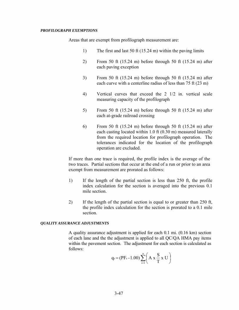
3-47
PROFILOGRAPH EXEMPTIONS
Areas that are exempt from profilograph measurement are:
1) The first and last 50 ft (15.24 m) within the paving limits
2) From 50 ft (15.24 m) before through 50 ft (15.24 m) after each paving exception
3) From 50 ft (15.24 m) before through 50 ft (15.24 m) after
each curve with a centerline radius of less than 75 ft (23 m)
4) Vertical curves that exceed the 2 1/2 in. vertical scale measuring capacity of the profilograph
5) From 50 ft (15.24 m) before through 50 ft (15.24 m) after
each at-grade railroad crossing
6) From 50 ft (15.24 m) before through 50 ft (15.24 m) after each casting located within 1.0 ft (0.30 m) measured laterally from the required location for profilograph operation. The tolerances indicated for the location of the profilograph operation are excluded.
If more than one trace is required, the profile index is the average of the two traces. Partial sections that occur at the end of a run or prior to an area exempt from measurement are prorated as follows:
1) If the length of the partial section is less than 250 ft, the profile
index calculation for the section is averaged into the previous 0.1 mile section.
2) If the length of the partial section is equal to or greater than 250 ft,
the profile index calculation for the section is prorated to a 0.1 mile section.
QUALITY ASSURANCE ADJUSTMENTS
A quality assurance adjustment is applied for each 0.1 mi. (0.16 km) section of each lane and the the adjustment is applied to all QC/QA HMA pay items within the pavement section. The adjustment for each section is calculated as follows:
∑=
⎟⎠⎞
⎜⎝⎛=
n
1i
ss x UTSA x 1.00) - (PF q

3-48
where:
qs = quality assurance adjustments for smoothness for 1 section PFs = pay factor for smoothness N = number of layers A = area of section, sq yd (m2) S = planned spread rate for material. lb/sq yd (kg/m2) T = conversion factor: 2,000 lb/ton (1,000 kg/Mg) U = unit price for the material, $/ton ($/Mg)
The quality assurance adjustment for smoothness, Qs, for the contract is the total of the quality assurance adjustnments, qs, on each section calculated by the following formula:
Qs = ∑ qs
Payment adjustments are made based on a zero blanking band on the final profile index in accordance with the following table. Regardless of the tabulated value, the maximum pay factor for a smoothness section where corrective action has been performed is 1.00.
PAY FACTORS FOR SMOOTHNESS
(PI0.0) ZERO BLANKING BAND Design Speed Graeter than 45 mph (70 km/h)
Profile Index in. / 0.1 mi.
(mm per 0.16 km)
Pay Factor, PFs
Over 0.00 to 1.20 in. (Over 0 to 30 mm) 1.06
Over 1.20 to 1.40 in. (Over 30 to 35 mm) 1.05
Over 1.40 to 1.60 in. (Over 35 to 40 mm) 1.04
Over 1.60 to 1.80 in. (Over 40 to 45 mm) 1.03
Over 1.80 to 2.00 in. (Over 45 to 50 mm) 1.02
Over 2.00 to 2.40 in. (Over 50 to 60 mm) 1.01
Over 2.40 to 3.20 in. (Over 60 to 80 mm) 1.00
Over 3.20 to 3.40 in. (Over 80 to 85 mm) 0.96
All pavement with a profile index (PI0.0) greater than 3.40 in. (85 mm) shall be corrected to a profile index less than or equal to 3.40 in. (85 mm).

4 Quality Control Procedures
Contractor Personnel QCP Manager
QCP Site Manager
Quality Control Technician
Milling Milling Plan
Equipment
Testing
Process Balance
Transportation of Mixture Truck Bed Cover
Unloading
Transfer Vehicles
Paving Paving Plan
Material Feed System
Grade and Slope
Joints
Asphalt Materials
Joint Compaction
Materials Sampling and Testing Mixture Properties
Mixture Temperature at Paver
Density
Coring
Smoothness

Response to Test Results
Pavement Smoothness
Documentation
Quality Control Plan QCP Approval
QCP Addenda

4-1
CHAPTER FOUR:
QUALITY CONTROL PROCEDURES
The foundation for a successful Quality Assurance program is the control
maintained by the Contractor to assure that all materials submitted for
acceptance conform to the contract requirements. To accomplish this, the
Contractor is required to have a functional Quality Control Plan (QCP) to
keep the process in control, quickly determine when the process goes out
of control, and respond adequately to bring the process back into control.
This chapter includes the minimum requirements for maintaining quality
control during production of QC/QA Hot Mix Asphalt. Acceptance test
results by INDOT are shared with the Contractor; however, results of
these tests should not be used for quality control purposes.
CONTRACTOR PERSONNEL
The Contractor personnel required to provide quality control on a QC/QA
Hot Mix Asphalt contract includes a QCP Manager, QCP Site Manager,
and a Quality Control Technician. One quality control person may
perform the duties of more than one position.
QCP MANAGER
The QCP Manager is responsible for the overall administration of the QCP
on the contract.
QCP FIELD MANAGER
The QCP Field Manager is responsible for the execution of the QCP and is
the liaison with the PE/PS. This person is required to be a Certified HMA
Field Supervisor and often is also the QCP Manager.
QUALITY CONTROL TECHNICIAN
The quality control technician is responsible for the following duties:
1) Quality control tests for temperature, density, and
smoothness
2) Pavement samples for quality control and INDOT
acceptance
3) Inspection to implement the QCP

4-2
MILLING
The Contractor is required to designate the procedures for milling the
existing material to include as a minimum the general procedures,
equipment, and testing that is conducted.
MILLING PLAN
The general procedures for asphalt milling, asphalt removal, PCCP
milling, scarification and profile milling, and transition milling are
required to be designated in the QCP.
EQUIPMENT
A description of the equipment required to mill, cut, and remove the
existing material is required to be designated.
TESTING
The procedure for measuring the macrotexture of the milled surface in
accordance with ITM 812 is required (Figure 4-1). The purpose of this
test is to measure the condition of the surface after milling in preparation
for resurfacing with HMA.
Figure 4-1. Macrotexture Test

4-3
A minimum frequency of one macrotexture test is required. The
requirements in accordance with Section 306 are as follows:
Macrotexture
Asphalt Scarification ≥ 2.2 for single course overlays
& Profile Preparation ≥ 1.8 for multiple course overlays
Asphalt Milling ≥ 2.2 for single course overlays
≥ 1.8 for multiple course overlays
PCCP milling ≥ 1.8
The procedure, frequency, and equipment for measuring the cross-slope
and longitudinal surface finish of the milled material is also required.
PROCESS BALANCE
The procedures for balancing the HMA operation, include the production,
transportation, placement, and compaction of the mixture. The purpose of
this balancing is to assure that there is the proper amount of HMA to
provide continual operation of the paver and that there is a sufficient
number of rollers to provide an effective compaction production rate
approximately equal to the paver speed. The QCP is required to state the
methodology for balancing the operation to include the plant production,
transportation, placement, and compaction of the mixture. One procedure
to determine whether the HMA operation is balanced compares the plant
production to the rate of mixture required to be delivered to the jobsite and
the actual paver production rate to the effective compaction production
rate (Figures 4-2 to 4-4). The following example explains the procedures
required to balance the HMA operations.
Example
Verify if the process is in balance for the following given information:
Mix Delivery
Tons to be Placed 3000 t
Hours of Paving 10 h
Plant Rating 350 t/h
Average Truck Capacity 20 t
Truck Cycle (minutes)
Delay at Facility 2
Load Time 3
Ticket & Tarp 2
Haul to Job 14
Delay on Site 5
Dump/Clean Up 5
Return Haul 14

4-4
Paving
Pavement width: 12 ft
Paving Thickness 2 in.
Minimum density 92% MSG
In-Place Target Density 94% MSG
Reference (Target) Density 143.0 #/ft3
Paving Efficiency Factor 0.80
Compaction
Breakdown roller: Dynapac CC-42A
Drum Width 66 in.
Maximum roller speed: 2 ½ mph
Vibrations/Minute 2700 VPM
Impact Spacing 10 impacts/ft
Number of Coverages to
Achieve Density (Test Strip) 2
Roller Efficiency Factor 0.80
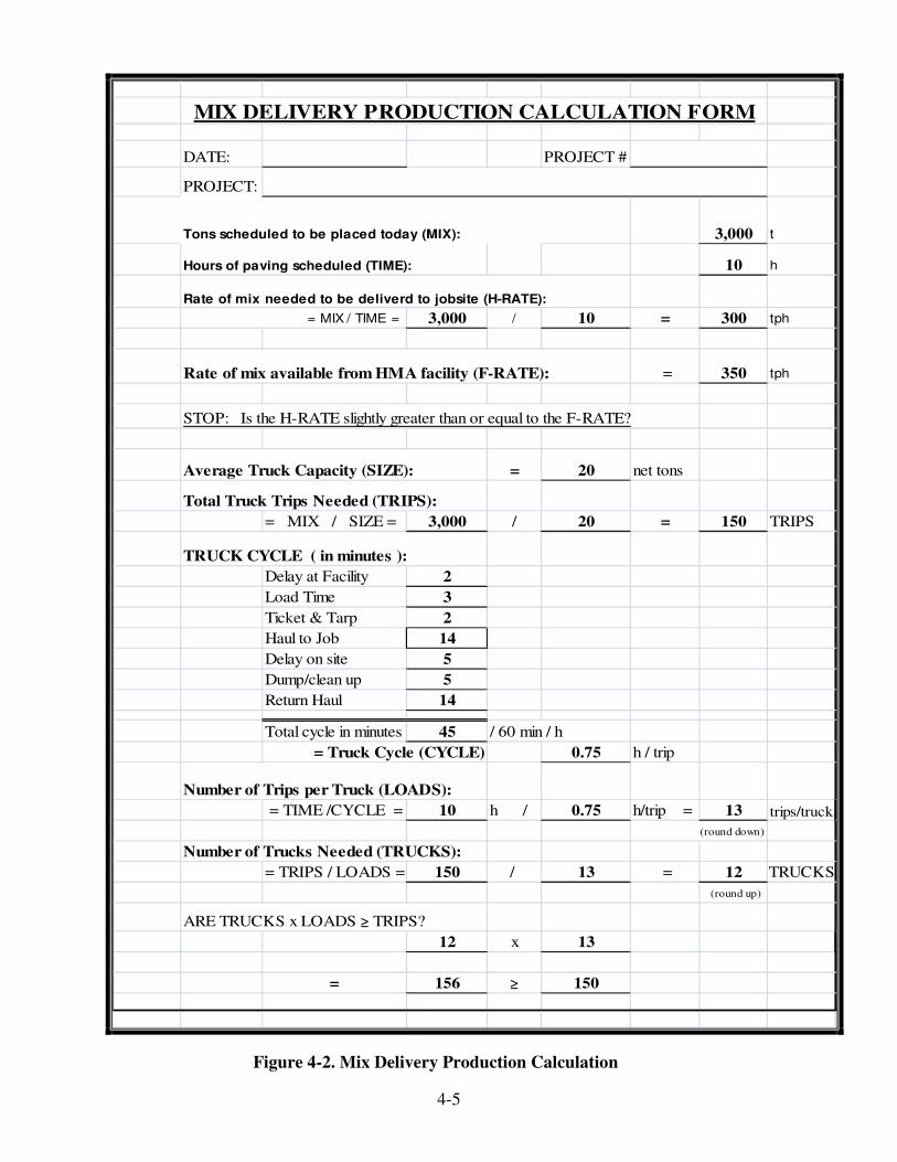
4-5
DATE: PROJECT #
PROJECT:
3,000 t
10 h
3,000 / 10 = 300 tph
Rate of mix available from HMA facility (F-RATE): = 350 tph
STOP: Is the H-RATE slightly greater than or equal to the F-RATE?
= 20 net tons
Total Truck Trips Needed (TRIPS):
= MIX / SIZE = 3,000 / 20 = 150 TRIPS
TRUCK CYCLE ( in minutes ):
Delay at Facility 2
Load Time 3
Ticket & Tarp 2
Haul to Job 14
Delay on site 5
Dump/clean up 5
Return Haul 14
Total cycle in minutes 45 / 60 min / h
0.75 h / trip
Number of Trips per Truck (LOADS):
= TIME /CYCLE = 10 h / 0.75 h/trip = 13 trips/truck
(round down)
Number of Trucks Needed (TRUCKS):
= TRIPS / LOADS = 150 / 13 = 12 TRUCKS
(round up)
ARE TRUCKS x LOADS ≥ TRIPS?
12 x 13
= 156 ≥ 150
= Truck Cycle (CYCLE)
MIX DELIVERY PRODUCTION CALCULATION FORM
Tons scheduled to be placed today (MIX):
Hours of paving scheduled (TIME):
Rate of mix needed to be deliverd to jobsite (H-RATE):
Average Truck Capacity (SIZE):
= MIX / TIME =
Figure 4-2. Mix Delivery Production Calculation
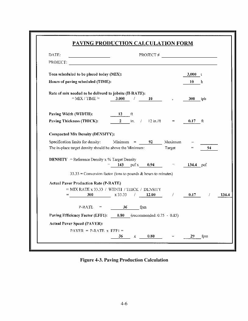
4-6
Figure 4-3. Paving Production Calculation

4-7
Figure 4-4. Compaction Production Calculation

4-8
TRANSPORTATION OF MIXTURE
The Contractor is required to designate the procedures for transportation
of the HMA from the plant to the paver.
TRUCK BED COVER
The procedure for when waterproof covers are used and the person that
directs their use is required.
UNLOADING
The procedures for unloading trucks and removing the remaining mixture
from the truck bed and bed apron are required.
TRANSFER VEHICLES
The procedures for the use of Material Transfer Devices or Windrow
Elevators, and the pans for crossing bridges with these devices is required.
PAVING
The Contractor is required to designate the procedures for placement of
the HMA.
PAVING PLAN
The general sequence, the widths and depths of paving for each of the
major courses, and the planned date for paving to begin and to be
completed on the contract are required.
MATERIAL FEED SYSTEM
The procedure for processing the mixture through the paver is required.
GRADE AND SLOPE
The procedure for controlling the grade and slope, including a description
of placing wedge and level courses, if applicable, is required.
JOINTS
The procedure for the construction of the longitudinal and transverse joints
is required. The starting and stopping procedures of the paver for
transverse joints is also required to be included.
ASPHALT MATERIALS
The source, source numbers, type, and grade of materials that are planned
for use for the tack coat, prime coat, or seal coat are required.

4-9
JOINT COMPACTION
The Contractor is required to designate the procedures for compaction of
the longitudinal and transverse joints.
MATERIALS SAMPLING and TESTING
The Contractor is required to designate the procedures for sampling and
testing HMA and the frequency of tests. The sampling locations and
procedures are not required to be the same procedures used for the
acceptance samples.
MIXTURE PROPERTIES
The HMA plant is required to be a HMA Certified Plant in accordance
with ITM 583. The location of the plant, owner, Producer name and plant
number are required.
The laboratory, procedures done for quality control testing of the mixture,
and the minimum frequency of samples is required.
MIXTURE TEMPERATURE at PAVER
The procedure for measuring the temperature of the mixture at the paver is
required. The temperature is required to be taken immediately behind the
paver prior to compaction at a minimum frequency of one test for each 1
hour of paving.
DENSITY
The procedure for measuring the density of the mixture utilizing a non-
destructive technique is required. Density tests are required to be taken on
the mainline and shoulders. The minimum frequency of tests is one test
each 1000 yd2. A nuclear test device, if used, is required to be calibrated
in accordance with ASTM D 2950 at a minimum frequency of once each
12 months. The nuclear gauge is required to be properly calibrated to the
mixture being placed.
The procedure for monitoring the temperature of the mix during
compaction to optimize the rolling pattern is also required.
Instead of a non-destructive testing device, an Intelligent Compaction (IC)
roller meeting the Department requirements may be used to measure the
stiffness and temperature of the mixture. A GPS radio and receiver unit
shall be mounted on the IC roller to monitor the drum locations and track
the number of passes of the roller. The IC roller shall include an
integrated on-board documentation system that is capable of displaying
real-time color-coded maps of IC measurement values including stiffness
response values, location of roller passes, pavement surface temperatures,
roller speeds, vibration frequencies, and amplitudes of the roller drums.

4-10
CORING
The plan for when cores are taken and the procedure for refilling the core
holes is required.
SMOOTHNESS
The procedure for measuring the smoothness of the pavement is required.
The annual certification of the profilograph in accordance with ITM 901
is also required to be included.
RESPONSE TO TEST RESULTS
The Contractor is required to take corrective action when quality control
test results exceed the established limits. The corrective actions are
required to be designated in the QCP. As a minimum, corrective actions
are required for the mixture tests from the pavement, the temperature
measurements, and the density.
PAVEMENT SMOOTHNESS
The Contractor is required to designate the procedures for correcting the
profile of non-complying pavement. Areas outside of the allowable
tolerance of Section 401.18 are required to be corrected.
DOCUMENTATION
The test results for quality control and documentation of equipment are
required to be maintained by the Contractor for a period of three years
upon completion of the contract. The records, either electronic and/or
hard copies, are required to be maintained at a readily accessible location
for review by INDOT at any time. As a minimum, the documentation is
required to include test results for the mixture, temperature, density, and
smoothness tests of the HMA pavement. Also, documentation of the
manufacture, model, and type of paver and rollers used each day of paving
is required. Any modifications to this equipment are required to be noted.
QUALITY CONTROL PLAN
The Contractor is required to submit a QCP that is contract specific and
states how the process control of materials, equipment, and operations are
maintained. As a minimum, the QCP is required to include the following
information for each contract.
1) The name, telephone number, duties, and employer of all
quality control personnel necessary to implement the QCP.
The minimum number of quality control personnel is
required to include a QCP Manager, QCP Site Manager,
and Quality Control Technician.

4-11
2) The procedure for milling to include the general
procedures, equipment, testing for macrotexture, and
testing for smoothness.
3) The procedure for balancing the HMA process to include
plant production, number of trucks, paver speed, and
compaction production rate procedure.
4) The procedure for transportation of the HMA to include the
use of truck bed covers, truck unloading procedures,
procedure for removal of mixture from the truck, and the
use of material transfer vehicles.
5) The procedure for paving to include a paving plan, the
material feed system, grade and slope control, joint
construction, and use of asphalt materials.
6) The procedure for compacting longitudinal and transverse
joints.
7) The procedures and frequency for sampling and testing the
HMA, to include the mixture behind the paver, the
temperature of the mixture at the paver, the density of the
mixture, the coring procedure, and the procedure for
measuring the smoothness.
8) The response to process control tests not within the
established requirements for mixture, density, and
smoothness tests.
9) The procedure for documentation of quality control tests
and the equipment used on the contract.
QCP APPROVAL
The QCP is required to be submitted to the PE/PS for review at least 15
calendar days prior to commencing HMA operations. The Contractor is
required to sign and date the QCP at the time of submittal to the PE/PS.
The PE/PS signs and dates the QCP if the contents of the QCP are in
compliance with the above-noted requirements. HMA operations are not
allowed to begin before the QCP has been accepted.
QCP ADDENDA
The QCP is required to be maintained to reflect the current status of the
operations, and revisions are required to be provided in writing prior to
initiating the change. The change may not be implemented until the
revision has been accepted.

5 Traffic Control
Basic Setup
Continual Inspection
Temporary Pavement Markings

5-1
CHAPTER FIVE:
TRAFFIC CONTROL
The need for standard traffic control is essential during roadway
construction to guide traffic safely and efficiently through what would
otherwise be hazardous areas.
Traffic control procedures are used at work sites to:
1) Warn motorists of the hazards involved and to
advise them of the proper manner for traveling
through the area
2) Inform the user of changes in regulations or
additional regulations that apply to traffic traversing
the area
3) Guide traffic through and around the work site
4) Delineate areas where traffic should not operate
BASIC SETUP
The required basic traffic control setup depends on several factors. Is the
work being performed under traffic or is the road closed? Is the road
closed to through traffic, but residences and businesses are located within
the work area for which access is required to be maintained? Is the work
zone at a fixed location or is the work zone moving down the road? Is the
work being performed on a two lane road or a multi-lane facility? Is the
work being performed on a travel lane or a shoulder? Is the work area on
an interstate only affected by infrequent ramps or on a roadway with a
number of driveways and at-grade intersections? The above factors, along
with others, all affect the required traffic control setup.
On individual projects, the following contract documents apply:
1) Indiana Manual on Uniform Traffic Control
Devices
1)2) Maintenance of Traffic Plan Sheets, if included in
the plans
Formatted: Bullets and Numbering

5-2
2)3) Standard Specifications Section 801
3)4) Section 801 Standard Drawings
4)5) Special Provisions in the Contract Information
Book
Section 801.03 of the Standard Specifications outlines the requirements
for the Certified Worksite Traffic Supervisor (CWTS). The CWTS is not
required to be on the contract site on a daily basis; however, the CWTS is
responsible for the layout and maintenance of all traffic control devices on
a contract. The CWTS should be involved in the initial layout of traffic
control devices as well as the layout associated with all construction phase
shifts that occur during the life of the contract.
For the purposes of this discussion, the primary emphasis will be related to
resurface work or other moving operations conducted on a travel lane
under traffic. Many of the principles discussed apply to other work
situations. The appropriate contract documents for the actual traffic
control setups required for other types of work should be reviewed on each
contract.
Two typical traffic control situations are illustrated in Figures 5-1 and 5-2.
The sign layouts noted in each figure are associated with the moving
operation only. Additional ground mounted signs are required at the
contract limits as noted in the Maintenance of Traffic Plans or Section 801
Standard Drawings.
A basic setup for a two-lane roadway with two-way traffic is shown in
Figure 5-1. This situation requires a flagger with advance warning signs
at both ends of the work area. All of the signs for this situation are to be
located in relation to the roadway in accordance with the Standard
Drawing. As the moving operation progresses down the road, relocation
of the signs to maintain proximity to the work area is necessary. If the
operation is allowed to progress too far in advance of the warning signs, a
motorist may conclude that there is no work being conducted. This may
result in a dangerous situation when the driver ultimately encounters the
work area.
Formatted: Bullets and Numbering
Formatted: Bullets and Numbering
Formatted: Bullets and Numbering

5-3
C
B
(optional) A
50 to 100 ft
50 to 100 ft
A
(optional)
B
C
Figure 5-1. Lane Closure on a Two-Lane Roadway Using Flaggers

5-4
Temporary white
edge line
500 ft
Work vehicle
Truck-mounted
attenuator
(optional)
Shoulder taper
(see Note 3)
500 ft
100 ft (optional)
Buffer space (optional) Buffer space (optional)
L
A
B
C
L
A
B
C
Shoulder taper
(see Note 3)
A - LONG-TERM AND INTERMEDIATE
B - SHORT-TERM
Figure 5-2. Stationary Lane Closure on a Divided Highway
5-5
Flaggers shall wear high-visibility safety apparel that meets the
Performance Class 2 or 3 requirements of the ANSI/ISEA 107-2004
publication entitled “American National Standard for High-Visibility
Apparel and Headwear”. Flaggers are required to be equipped with 24 in.
diameter STOP/SLOW paddles. The use of these paddles should be
limited to emergency situations. Flaggers should also be equipped with
two way radios if they will not be able to see each other.
Basic flagging procedures are shown in Figure 5-3. All flaggers are
required to remain alert while conducting flagging duties. Additional
personnel available to provide breaks for the flaggers may be necessary.
The following additional requirements for the flagger are necessary:
1. Stand either on the shoulder adjacent to the road user being
controlled or in the closed lane prior to stopping road users
2. Stand only in the lane being used by moving road users
after the road users have stopped
3. Be clearly visible to the first approaching road user at all
times
4. Be visible to other road users
5. Be stationed sufficiently in advance of the workers to warn
them of approaching danger by out-of-control vehicles with
an audible warning device such as a horn or whistle
6. Stand alone, away from other workers, work vehicles, or
equipment
Flagger and other crew members should be alert for trucks associated with
the work as they enter and leave the work area. Material delivery trucks
entering or exiting the work zone are often moving slower than the
through traffic and may cause traffic slowdowns. Also, motorists may
follow these vehicles into the work area.
Other considerations when setting up flagging operations include
intersections, driveways, and other site specific features within the work
area. Flaggers should not stand in the center of an intersection.
Additional flaggers may be necessary to prevent motorists from entering
the available travel lane from an intersecting road or driveway.

5-6
To
Stop
Traffic
7’
24"
24"
Traffic
Proceed
To Alert
and Slow
Traffic
Figure 5-3. Flagging Procedures
Properly Trained Flaggers
• give clear messages to drivers
as shown
• allow time and distance for
drivers to react
• coordinate with other flaggers
Properly Equipped
Flaggers
• approved sign paddles
• paddles are not to be used in a
signalized intersection
• approved Personal Protective
Garments (PPE)
• brightly colored hat for better
visibility
• retroreflective night equipment
Proper Flagging Stations
• good approach sight distance
• highly visible to traffic
• never stand in moving traffic
lane
• always have an escape route
Proper Advance Warning Signs
• always use warning signs
• allow reaction distance from
signs
• remove signs if not flagging
Flags should only be used in
emergency situations or when a
paddle would present a
conflicting message to the
motorist. Flags shall be a
minimum of 24in. x 24in., red in
color, and mounted on a staff
about 3ft long.

5-7
The basic setup for a multi-lane roadway is shown in Figure 5-2. A
flagger is not normally required in this situation since advance warning
signs are sufficient to warn motorists. A set of signs is required to be
located on both the outside and inside shoulders and installed in relation to
the roadway in accordance with the Standard Drawing. The flashing
arrow sign is placed on the pavement shoulder a calculated distance from
the beginning of the work area. Channelizing devices are required to
direct motorists from the lane to be closed to the adjacent open lane. For
daylight operations, the use of cones or tubular markers for the
channelizing devices is acceptable. For protection of nighttime work
areas, drums or cones with a minimum height of 2 ft-4 in. are typically
required.
CONTINUAL INSPECTION
All traffic control devices used at roadway work sites are required to be
inspected daily to ensure the safety of the work force, the traveling public,
pedestrians, as well as to protect the freshly placed mat. While the
performance of these duties may be delegated to anyone, the CTWS is
ultimately responsible for the inspection and maintenance of all traffic
control devices on the contract. If an inspection determines that individual
traffic control devices require reinstallation or replacement, the individual
making that inspection is required to know how to contact the CTWS or
designee to facilitate the repair or replacement of the defective devices.
TEMPORARY PAVEMENT MARKINGS
As the paving operation progresses down the road, any pavement
markings that are covered by the newly placed mat are required to be
replaced by temporary markings. The temporary pavement markings are
required to be placed prior to reopening the work area to traffic. Section
801.12 of the Standard Specifications includes the requirements associated
with temporary pavement markings. This information includes which
markings are required and which marking materials are appropriate.
There are also requirements associated with the length of time that the
temporary markings will be in place and for situations where the traffic
markings are used to indicate no passing zones.
6 Preparation of Surface
Subgrade Treatment
Proofrolling
Milling
Patching
Wedge and Level
Base Widening
Cleaning
Tacking Application
Curing

6-1
CHAPTER SIX:
PREPARATION OF SURFACE
HMA pavements may be placed:
1) Over existing pavements, either HMA or concrete
2) On newly constructed subgrade, aggregate base or HMA
base courses
3) For widening contracts, on a combination of existing
pavement and a base course
The existing surface is required to be compacted, stable, and free from
mud or other foreign matter before placing the new HMA pavement.
Preparation for a HMA course may include subgrade treatment,
proofrolling, milling, patching, leveling, wedging, and cleaning. The
surface is required to be inspected for cross slope, potholes, base failure,
dips, and bumps to determine the need for corrections.
The requirements of the Contractor for surface preparation are designated
in the Quality Control Plan (QCP) for the contract.
SUBGRADE TREATMENT
Subgrade treatments on which HMA Base may be placed are specified in
Section 207. One of several Subgrade Treatment Types may be allowed
and is specified in the Contract Plans and Section 207.04. One subgrade
treatment procedure is chemically modifying the soil (Figure 6-1).
Figure 6-1. Chemically Modifying Soil

6-2
PROOFROLLING
In some cases the subgrade may be accepted by proofrolling according to
Section 203.26. A fully legally loaded tri-axle dump truck may be
substituted for the pneumatic tire roller. Proofrolling is a visual means of
determining whether or not the subgrade is compacted or stable and
suitable to receive HMA base. A HMA base is required to be placed on an
unyielding surface to sustain the design traffic loads when completed.
MILLING
Milling is part of a pavement rehabilitation process where a portion of the
old HMA pavement or PCCP is removed or planed by a milling machine
in preparation for an HMA overlay (Figure 6-1).
Figure 6-1. Milling Machine
Milling is done prior to repaving for many reasons including:
1) Removal of distressed pavement
2) Improve smoothness
3) Reshape cross slopes
4) Eliminate shoulder work after new layer(s) are placed (mill and
fill)
5) Maintain curb exposure
6) Maintain clearances and other drainage features
7) Transitions to approaches or other pavement where new paving
stops
8) Roughing the existing surface texture to remove asphalt joint
material

6-3
There are several different pay items for milling depending on the
application. The specific type of milling is specified in the contract.
Milling is paid by the square yard (SYS) and is specified in Section 306.
The types of milling include:
1) Approach Milling
2) Asphalt Milling
3) Asphalt Removal
4) PCCP Milling
5) Scarification/Profile Milling
6) Transition Milling
The macrotexture after milling is required to be checked in accordance
with ITM 812 and Section 306.04. Milling procedures and procedures to
check macrotexture and cross slopes are required to be described in the
QCP.
The millings produced become the property of the Contractor and may be
transported to a HMA plant facility for use as recycled asphalt pavement
(RAP). When specified, millings may be used to construct shoulders.
PATCHING
Unsuitable areas are required to be identified and marked for removal by
INDOT personnel. Areas to be removed include potholes, base failures,
unstable mixes in place, and spots with excess asphalt. If the pavement to
be patched is overlaid, the edge of the removal area is not required to be
sawed. The removal area is required to conform to the marked lines to
minimize over-breakage. If the patch is not overlaid, a neat edge for the
patch is required to be attained by sawing. The size of the patches
depends on the conditions found on the contract. The size and depth of
the excavation are required to be measured and recorded for determination
of the pay quantities. A typical full depth HMA patch section is illustrated
in Figure 6-2.
Where unstable material is encountered below the existing pavement in
the base, subbase, or subgrade, this material is removed. The sides of the
excavation are required to be vertical. The HMA may not be properly
compacted against sloping sides. The bottom of the removal area is
compacted and the area backfilled with suitable material up to the bottom
of the existing pavement. The backfill material is placed in 6 in. lifts and
compacted thoroughly.

6-4
Figure 6-2. Typical Full Depth HMA Patch Section

6-5
Before placing the HMA patching material, the edges of the existing mat
are cleaned and tacked with asphalt to ensure a bond between the old
surface and the new mix. In placing the patching mixture, the depth of
each lift cannot exceed four times the maximum nominal particle size as
indicated on the DMF. Each lift is required to be compacted before
placing the next lift. The surface of the patch is required to be placed
approximately 1/4 in. high, and be flush with the existing surface after the
compaction is completed.
Patching operations are scheduled so that all removal areas opened during
the day are completely patched at the close of the work day to allow
opening the lane to traffic. When a patch cannot be completed, the HMA
is backfilled, compacted, and a temporary surface placed to carry traffic
during the night. All temporary work is at the expense of the Contractor
and is avoided if at all possible.
WEDGE AND LEVEL
When the surface of a pavement is irregular, the surface is required to be
brought to a uniform grade and cross section. Normally, milling is
specified to correct this problem; however, sometimes a leveling course is
used. Wedge and level may not be the best practice since proper
compaction is difficult when non-uniform thicknesses are placed. The
HMA materials used are specified in the contract and Section 402.07(d).
Wedges of HMA are used to level sags and depressions in an old
pavement prior to the paving operation.
Leveling and wedging material is required to be placed in lifts to ensure
compaction. The top of each lift is required to be parallel to the desired
profile or cross section as shown in Figure 6-3.
Figure 6-3. Correct Wedge and Level
Because of the difficulty of feathering the edges of HMA mixtures,
placing the material in lifts parallel to the existing surface (Figure 6-4)
usually results in rough patches that reflect to the finished surface.
Figure 6-4. Incorrect Wedge and Level

6-6
The number and lengths of lifts are determined by the allowable lift
thickness and the depth of the area to be leveled (Figure 6-5).
Figure 6-5. Wedge and Level Lifts
Wedges are also used to re-establish the crown on a tangent roadway or
superelevation on a curve (Figure 6-6). The number of wedge courses
necessary to rebuild the crown or superelevation depends on the total
depth to be placed and the maximum aggregate size in the mix.
Figure 6-6. Crown Wedge
The finished depth of any course is required to be at least 1.5 times but not
more than 6 times the maximum particle size as shown on the DMF or
JMF. Feathering may be less than the minimum thickness requirements.
Acceptance of patching material and wedge and level is done on the basis
of a Type D certification. This certification is required to be delivered to
the job-site each morning before any mix may be accepted. Typically, the
first truckload of material is delivered with the Type D certification. The
Type D certification is required to report the air voids and binder contents
of the mix. The allowable deviations from the DMF are 1.5 % for air voids
and 0.7 % for the binder content. If the results do not comply with these
requirements, the HMA is processed as a failed material.

6-7
BASE WIDENING
With the increased emphasis on rehabilitation of existing roadways, more
contracts require widening and resurfacing. The width of the widening,
either on one or both sides of the pavement, and the type of base mixture
are indicated on the plans or specified in the contract.
The area to be widened is usually excavated with a trenching machine,
milling machine or motor grader, depending on the width. The subgrade
is then compacted and the widened area backfilled to the planned line and
grade. When the profile and alignment of the existing pavement edge is
satisfactory, the edge may be used as a guide in excavating the widening
trench. However, when either of these is irregular, field work and
planning are required to establish line and grade before the Contractor
begins work. Pavements to be surfaced are sometimes warped with
variable or inverted crowns. On tangents, one edge may be higher than
the surface at the centerline.
Typical examples of warped and non-uniform crowned pavements are
shown in Figure 6-7. Sections needing correction may have excessive
crown, one edge higher than the other, or no crown. In each instance,
wedging is required. The controlling point for establishing the final
profile is indicated by the arrows in Figure 6-7. The wedges are required
to be placed before excavation of the widening sections is started so that a
good reference for line and grade is established.
Figure 6-7. Warped and Non-Uniform Crowned Pavements

6-8
CLEANING
The existing surface is required to be cleaned before applying the tack
coat. Normally, cleaning may be done by sweeping, but sometimes mud
or other foreign matter is required to be removed with shovels and hand
brooms. Where dirt is embedded, a pressure washer or compressed air
may be required for thorough cleaning. Typically power brooms are used
for sweeping (Figure 6-8).
Excess asphalt material at cracks and joints is required to be removed to
the elevation of the existing surface or below. Failure to remove the
excess asphalt materials results in "bleeding" of the asphalt through the
subsequent courses causing bumps or other irregularities in the surface.
Figure 6-8. Power Broom
TACKING
A tack coat is the application of asphalt material to an existing paved
surface (Figure 6-9). The primary purpose of the tack coat is to adhere the
newly placed HMA to the old surface. Tack coats are covered by Section
406. The material that is used for tacking is Asphalt Emulsion, AE-T, AE-
PMT, SS-1h or AE-NT (Section 902.01(b)).

6-9
Figure 6-9. Tack Application
APPLICATION
Tack coats are applied to have the least inconvenience to traffic and to
permit one-way traffic without tracking or picking up of the material.
Typically, nearly all of the tacked area is covered by mix each day. Tack
coat may not be applied to a wet surface. The rate of application,
temperature, and areas to be treated are required to be approved by the
PE/PS before the application of tack material. In the event of rain or other
circumstances where the tack coat remains uncovered, the material may be
lightly sanded and provisions made for traffic safety.
The two essential requirements of a tack coat are:
1) The application of the asphalt material is required to be
very thin
2) The material is required to uniformly cover the entire
surface of the area to be paved without puddling or
streaking
The asphalt material is required to be uniformly applied with a pressure
distributor at a rate from 0.03 to 0.08 gallons per square yard unless
otherwise specified or directed. The tack coat is not applied heavily. Too
little tack is better than too much. The texture and absorption of the
existing surface affects the desirable application rate.

6-10
The application rate depends on the speed of the truck, the length of the
spray bar, the pump pressure, and the pump speed. Each distributor is
equipped with charts or computerized systems for determining the correct
setting for the pump and truck speed for any given spray bar length and
application rate. When the Contractor cannot get uniform coverage and
streaking or puddling continues despite adjustments to the distributor, the
use of a burlap drag may be required. The tack coat may be mopped,
broomed, or squeegeed to obtain a more even distribution or to facilitate
curing.
Areas inaccessible to the spray bar are tacked with the hand spray.
Extreme care is required to be taken with the hand spray to obtain uniform
coverage without puddling.
CURING
Time is required to allow the asphalt emulsions to break and cure before
the HMA is placed on the tack coat. The emulsion turns from brown to
black and becomes sticky when the material "breaks" and the water
evaporates.

7 Mix Placement and Compaction
Weather Limitations
Asphalt Materials Prime Coats
Tack Coats
Base Seals
Fog Seals
Joint Adhesive
Distributors
Mixture Transportation Haul Trucks
Material Transfer Vehicles
Mix Temperature and Appearance
Placement of Mixture Pavers
Paver Operation
Start-Up
Alignment
Grade and Slope Control
Transverse Joints
Longitudinal Joints
Widening Machines
Care and Cleaning of Pavers
Paving Crew Responsibilities

Compaction Rollers
Compaction of HMA
Specified Rollers
Plant Production-Number of Rollers
Compaction Controlled by Density
Widening Rolling Patterns
Roller Operator Responsibilities

7-1
CHAPTER SEVEN:
MIX PLACEMENT AND COMPACTION
The procedures for mix placement and compaction are in general specified
by the Contractor in the Quality Control Plan for QC/QA HMA (401),
HMA (402) and SMA (410) mixtures for the contract.
The paving and compaction equipment on a HMA contract are
distributors, pavers, material transfer devices, widening machines, rollers,
and hauling units (trucks). Before paving operations may be started, all of
the paving equipment is required to be checked for conformance with the
Specifications and the Contractor’s Quality Control Plan. A pre-paving
meeting is a good practice to assure that all of the personnel involved in
the paving and compaction operation understand the procedures to be used
on the project. Pre-paving meetings should be held prior to beginning
paving operations for the project, prior to phase changes in a project, and
at the beginning of each construction season for multi-year projects.
____________________________________________________________
WEATHER LIMITATIONS
Hot mix asphalt may be placed only when weather conditions are
favorable. Placing the mix on a cold surface or when the air temperature
is low causes the mix to cool too quickly. No mixture may be placed on a
frozen subgrade. QC/QA HMA courses of less than 138 lb/yd2 and SMA
mixtures are required to be placed when the ambient temperature and the
temperature of the surface on which the mix is to be placed is 45° F or
above. For Non-QC/QA HMA, minimum temperatures have been
established and are summarized as follows:
HMA Courses Air
Temperature
Surface
Temperature
Equal to or greater than
220 lb/yd2
32° F 32° F
Equal to or greater than
110 lb/yd2, but less than
220 lb/yd2
45° F
45° F
Less than 110 lb/yd2 60° F 60° F
HMA courses may be placed at lower temperatures provided the density
of the HMA course is controlled by cores as indicated in Section 402.16.

7-2
Paving mixtures may not be laid on wet surfaces or when other conditions
are obviously not suitable, even if air and surface temperatures are within
the limits. Since rain may be prevalent at the paving site but not at the
plant, a means of rapid communication is required to be provided to
prevent having several loads of material delivered which may not be used.
ASPHALT MATERIALS
PRIME COATS
Prime coats are used on rubblized concrete pavements to protect the
pavement from wet weather. This waterproofing layer prevents excess
moisture absorbing into the pavement during rain before paving. The
prime coat also allows the pavement to be used for light traffic, binds
together any dust on the surface and promotes the bond between the
pavement and the HMA overlay. Section 405 includes the requirements
for the allowable materials, equipment, preparation of surface, and
application rate of asphalt materials and cover aggregate for prime coats.
The asphalt material is not allowed to be applied on a wet surface, when
the ambient temperature is below 50° F, or when other unsuitable
conditions exist, unless approved by the Engineer. The rubblized concrete
pavement to be treated is required to be shaped to the required grade and
section, free from all ruts, corrugations, or other irregularities, and
uniformly compacted and approved.
TACK COATS
Tack coats are used to ensure a bond between an existing HMA mixture
and the new HMA mixture. If a good bond is not formed, slippage of the
overlay in a longitudinal direction by traffic may occur. Section 406
includes the allowable materials, equipment, and application rate of the
asphalt material for tack coats. The existing HMA mixture to be treated is
required to be free of foreign materials that may be detrimental to the
purpose of the tack coat. Tack coats are not allowed to be applied to a wet
surface. The rate of application and areas to be treated are required to be
approved prior to application. Excessive tack coat is required to be
corrected to obtain an even distribution of the material.
BASE SEALS
Base seals are used on dense graded base mixtures that are immediately
below open graded mixtures within the pavement structure. The base seal
prevents water carried through the open graded mixture from penetrating
the dense graded base course and saturating the subgrade below. Section
415 includes the requirements for base seals.

7-3
FOG SEALS
Fog seals are used in conjunction with a joint adhesive to prevent water
from penetrating the pavement structure. Because of the difficulty in
compacting the asphalt mixture at the longitudinal joint, the fog seal is
applied to assist in sealing the material on each side of the joint. If a
milled centerline corrugation is applied, the fog seal will seal any cut
aggregates that may occur because of the corrugations. Section 412
includes the material and construction requirements for a fog seal.
JOINT ADHESIVE
Joint adhesives are used between adjacent mats to provide a waterproof
seal at the joint. The joint adhesive is a hot asphalt material that is applied
using a wand applicator on the joint face 1/8 in. thick at the temperature
recommended by the manufacturer. The application of the adhesive is
made within the same day, but at least 15 minutes prior to construction of
the longitudinal joint. RSP 401-R-581 includes the material and
construction requirements for a joint adhesive.
DISTRIBUTOR
A distributor is used to apply the liquid asphalt material used for the prime
and tack coats. The distributor consists of an insulated tank mounted on a
truck or trailer. A power-driven pump forces the asphalt through a system
of spray bars and nozzles onto the construction surface. A burner, usually
oil-fired with flues within the tank, is used to heat the asphalt to the proper
application temperature. The major units for a typical distributor are
indicated in Figure 7-1.
The distributor is required to:
1) Maintain the liquid asphalt at a uniform temperature
2) Apply material at a uniform rate
3) Apply material at variable widths
The distributor is required to be equipped with:
1) Accurate volume measuring gauges or a calibrated tank
2) A thermometer for measuring temperatures
3) A power unit for the pump
4) Full circulating spray bars to prevent material cooling in
the spray bars. The spray bars are required to be adjustable
vertically.

7-4
Figure 7-1. Distributor
MIXTURE TRANSPORTATION
HAUL TRUCKS
Haul trucks (Figure 7-2) used to transport the HMA to the paver should be
continuously monitored. 402.13 requires HMA in the haul trucks to be
protected by tarps from adverse weather conditions or foreign materials.
Adverse conditions include, but are limited to, precipitation or
temperatures below 45° F. The QCP is required to include the criteria for
when waterproof covers are used and designate the person responsible for
directing the use of these covers. Also, the procedures for truck unloading
and for removing the remaining mixture from the truck bed and apron are
required to be included in the QCP. Some daily checks of the trucks that
should be made include:

7-5
1) Truck beds that are leaking mix because the gates are not tight
2) Foreign material in the mix that would indicate the beds were not
clean when loaded. When tarps are used, they should overlap the
bed of the trucks enough to prevent rain and foreign material from
getting into the mix.
3) The appearance of the mix before the load is dumped
4) Evidence of the excess use of anti-adhesive agent
5) No hydraulic or fuel leaks
Figure 7-2. Haul Truck
Truck Driver Responsibilities
The truck driver responsibilities include assuring that the truck is loaded
properly and that there is a consistent delivery of HMA in a homogeneous
mass into the paver hopper or transfer unit without causing segregation.
Specific responsibilities of the truck driver when using a dump truck
include:
1) Load the truck using multiple drop procedures
2) Tarp the load as required to maintain mix temperatures
3) Proceed safely to the paving site and line up properly in
front of the paver or transfer unit
4) Back into the paver or transfer unit without bumping

7-6
5) Open the tail gate and discharge the mixture in a mass
when the paver or transfer unit makes contact with the
truck
6) Continue to raise the bed while moving to allow the
material to be discharged in a mass
7) Exit immediately when the truck is empty
An alternate procedure for unloading the truck into the paver is possible
by raising the bed prior to releasing the tailgate. The procedure is as
follows:
1) Back the truck into discharge position stopping short of the
paver by 1 to 2 inches
2) Raise the bed slowly until the load shifts to the rear. The
paver operator will start the paver forward when he
observes the shift of material
3) Release the tail gate when the forward motion is detected
and continue to raise the bed as directed
Dump Person Responsibilities
The dump person responsibilities include safely directing the truck into the
correct position for discharging the truck into the hopper. Specific
responsibilities include the following:
1) Be aware of the safety in and around the paving site,
especially overhead obstructions, and warn the paving crew
if dangerous situations arise
2) Safely direct the truck into the discharge position without
bumping the paver and assuring alignment of the paver and
truck to make steering to reference points much easier
3) Watching the hopper to assure that the hopper does not run
low or empty. The hopper should be at least 25% full at all
times.
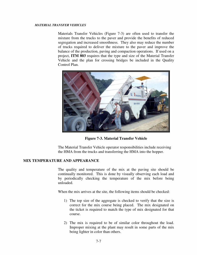
7-7
MATERIAL TRANSFER VEHICLES
Materials Transfer Vehicles (Figure 7-3) are often used to transfer the
mixture from the trucks to the paver and provide the benefits of reduced
segregation and increased smoothness. They also may reduce the number
of trucks required to deliver the mixture to the paver and improve the
balance of the production, paving and compaction operations. If used on a
project, ITM 803 requires that the type and size of the Material Transfer
Vehicle and the plan for crossing bridges be included in the Quality
Control Plan.
Figure 7-3. Material Transfer Vehicle
The Material Transfer Vehicle operator responsibilities include receiving
the HMA from the trucks and transferring the HMA into the hopper.
MIX TEMPERATURE AND APPEARANCE
The quality and temperature of the mix at the paving site should be
continually monitored. This is done by visually observing each load and
by periodically checking the temperature of the mix before being
unloaded.
When the mix arrives at the site, the following items should be checked:
1) The top size of the aggregate is checked to verify that the size is
correct for the mix course being placed. The mix designated on
the ticket is required to match the type of mix designated for that
course.
2) The mix is required to be of similar color throughout the load.
Improper mixing at the plant may result in some parts of the mix
being lighter in color than others.
7-8
3) All aggregates are required to be coated with asphalt. Large coarse
aggregate may not be entirely coated because of the rough surface
texture.
4) Puddles of asphalt sitting on the mix indicate insufficient mixing.
These loads are not acceptable.
5) Blue smoke rising from the mix is an indication that the
temperature of the mix is too hot. The temperature of the mix is
checked to confirm this observation. A smoky load may also
indicate the use of fuel oil as an anti-adhesive in the truck bed.
6) The aggregate particles are required to be distributed throughout
the mix. If the coarse aggregates tend to roll out of the truck into
the paver at the very beginning or very end of the load, the mix is
segregated. Segregation is the most common mix problem.
7) Specifications require the maximum plant discharge temperature to
be no more than 315 °F when PG 58-28, PG 64-22, PG 64-28, or
PG 70-22 binders are used and not more than 325 °F when PG 70-
28 or PG 76-22 binders are used. Mixture temperatures at the
paver site should never be higher than these temperature
limitations.
To attain the best results, HMA mixtures are required to be placed at the
optimum temperature. The temperature of each mixture at the time of
spreading is required to not be more than 18° F below the minimum
mixing temperatures indicated on the DMF/JMF for non-QC/QA
mixtures. Normally, a surface thermometer is sufficient for obtaining an
accurate temperature of the mixture.
PLACEMENT OF MIXTURE
PAVERS
HMA mixtures are spread and finished with the use of paver finishers and
widening pavers. The HMA paver spreads the mixture in either a uniform
layer of a desired thickness or a variable layer to a desired elevation and
cross section. Widening pavers are used for widths of less than 8 ft where
the normal paver cannot operate.
There are many types of pavers available for placing HMA mixtures. The
discussion in this chapter does not include all of the variations available on
all pavers. Figure 7-4 illustrates the various components that are common
to many pavers.

7-9
Figure 7-4. HMA Paver
The paver consists essentially of a tractor and a screed. The tractor
receives, conveys, and augers the mixture to the screed and propels the
screed forward. The tractor may be mounted on either rubber tires or
crawlers. In addition to the engine, the tractor unit has a hopper for
receiving mix from the haul trucks or Material Transfer Device, conveyors
to move the mix through the flow control gates to the augers, flow gates to
regulate the flow of mixture to maintain uniform auger speed, and augers
to evenly spread the mix in front of the screed. If haul trucks are used,
rollers are mounted on the front of the tractor to push the trucks during the
dumping process. The rollers turn freely so the trucks have little effect on
paver operation. The screed conducts the actual placing of HMA to the
desired width and thickness or elevation as indicated in Figure 7-5. The
screed is towed by the tractor and is free to float up or down until the
bottom of the screed is parallel with the grade over which the screed is
traveling.
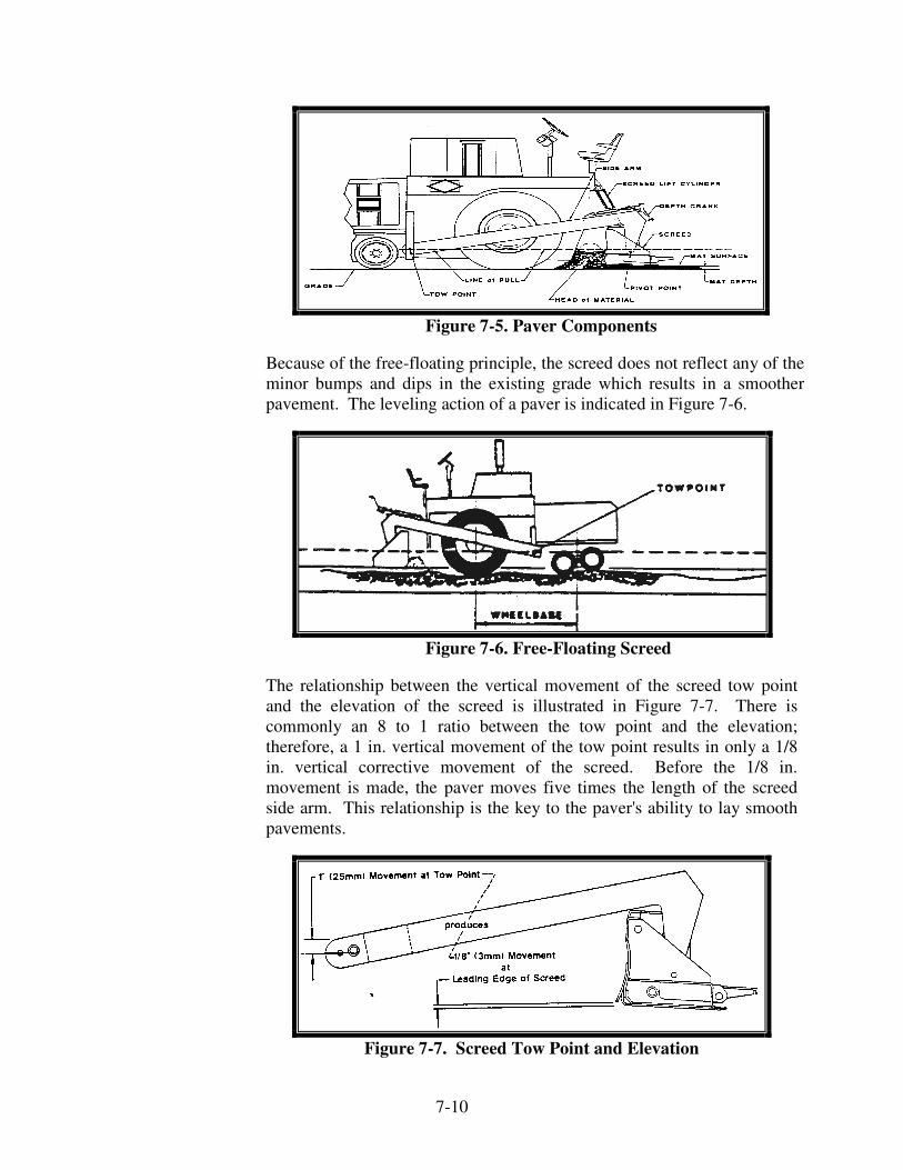
7-10
Figure 7-5. Paver Components
Because of the free-floating principle, the screed does not reflect any of the
minor bumps and dips in the existing grade which results in a smoother
pavement. The leveling action of a paver is indicated in Figure 7-6.
Figure 7-6. Free-Floating Screed
The relationship between the vertical movement of the screed tow point
and the elevation of the screed is illustrated in Figure 7-7. There is
commonly an 8 to 1 ratio between the tow point and the elevation;
therefore, a 1 in. vertical movement of the tow point results in only a 1/8
in. vertical corrective movement of the screed. Before the 1/8 in.
movement is made, the paver moves five times the length of the screed
side arm. This relationship is the key to the paver's ability to lay smooth
pavements.
Figure 7-7. Screed Tow Point and Elevation

7-11
Section 409 requires that a paver (Figure 7-8):
1) Be a self-contained power propelled unit
2) Be equipped with an activated (vibratory) screed or strike-
off assembly capable of being heated for the full length,
including extensions
3) Be capable of spreading and finishing mix in lane widths
indicated on the typical sections for the contract
4) Be equipped with automatic grade and slope controls if the
width of the roadway or shoulder to be paved is 8 ft or
wider. The operator's control panel is required to have
gauges that indicate compliance with the established grade
and slope.
5) Have a grade leveler (commonly called a ski or mat
reference) for attachment to the paver to activate the
automatic grade control
Figure 7-8. Paver Screed Controls

7-12
The automatic screed controls may be set for manual, semiautomatic, or
automatic operation on most pavers. Automatic screed controls typically
have the following main components:
1) Infrared Sonic Sensors
2) Non-Contact Sensors
3) Control station
4) Slope control
5) Motors and hydraulic cylinders to change the screed tilt
The grade sensor rides on a stringline, a ski, or a joint matcher to detect
changes in elevation and transmit the information electronically to the
controls. The electronic controls may be checked by varying the position
of the grade sensor and observing if the screed controls react to make the
correct adjustment. When the ski is used, the grade sensor is required to
always ride on the center of the ski so that all elevation changes are
averaged.
Use of the automatic controls further enhances the paver's capability to
produce a smooth pavement surface regardless of irregularities in the
surface being paved. Crown or superelevation slope is controlled by the
slope sensor or pendulum set for the desired slope. Once the screed is set
for the desired mat thickness and slope, the automatic controls activate the
motors or cylinders to change the screed tilt to automatically compensate
for road surface irregularities. Automatic slope and grade controls are
required to be used as outlined in the QCP.
PAVER OPERATION
The operation of the paver is different for the various types of equipment
used in the HMA Industry. The information provided in this section may
or may not apply to all pavers and is intended to provide information on
the general operations of a paver.
Controlling the vertical position of the free-floating screed, with respect to
the grade surface over which the paver is moving, is the primary concern
in producing high quality paving.
Several factors, such as the paving speed, head of material, mix
consistency, pre-compaction, and screed angle of attack influence the
vertical position of the screed. If any one of these factors is varied during
the paving operation, the variation causes a change in the mat depth,
density, and/or texture.
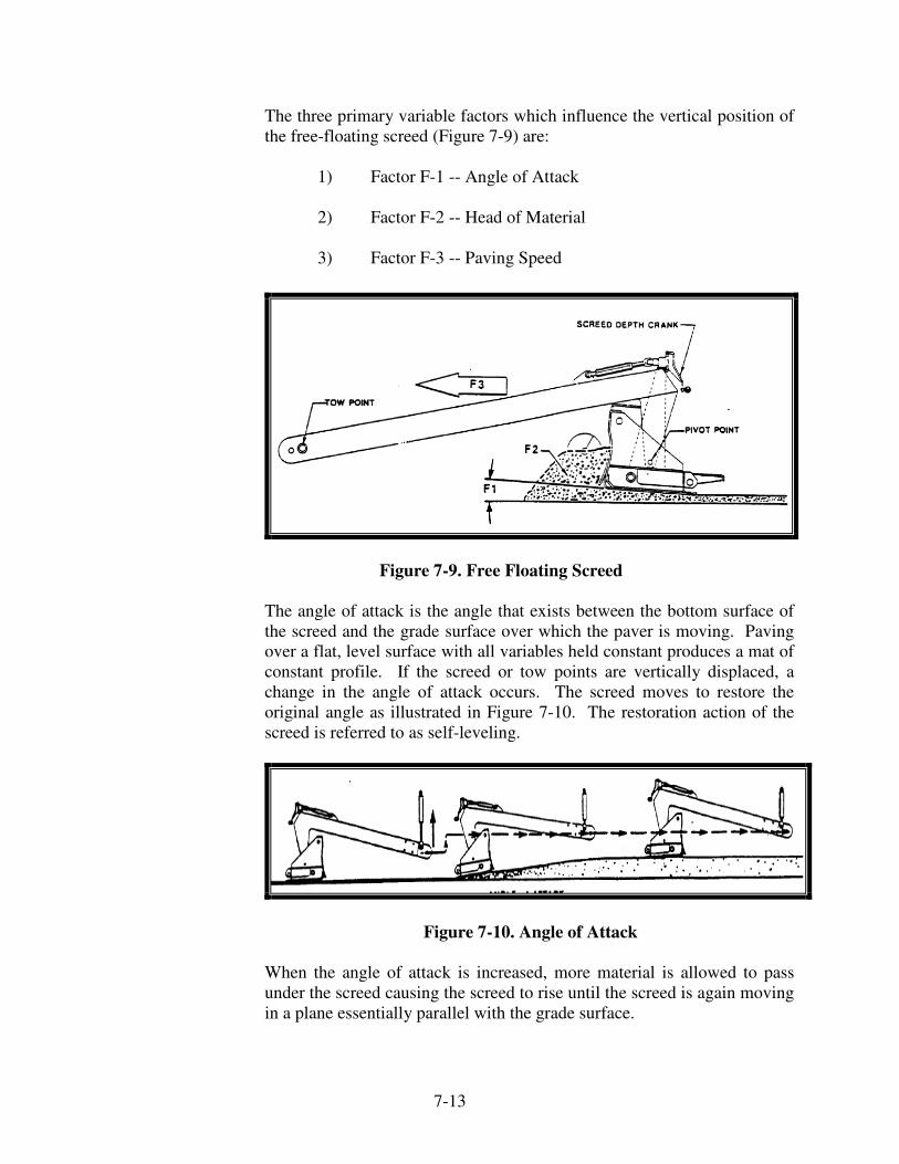
7-13
The three primary variable factors which influence the vertical position of
the free-floating screed (Figure 7-9) are:
1) Factor F-1 -- Angle of Attack
2) Factor F-2 -- Head of Material
3) Factor F-3 -- Paving Speed
Figure 7-9. Free Floating Screed
The angle of attack is the angle that exists between the bottom surface of
the screed and the grade surface over which the paver is moving. Paving
over a flat, level surface with all variables held constant produces a mat of
constant profile. If the screed or tow points are vertically displaced, a
change in the angle of attack occurs. The screed moves to restore the
original angle as illustrated in Figure 7-10. The restoration action of the
screed is referred to as self-leveling.
Figure 7-10. Angle of Attack
When the angle of attack is increased, more material is allowed to pass
under the screed causing the screed to rise until the screed is again moving
in a plane essentially parallel with the grade surface.
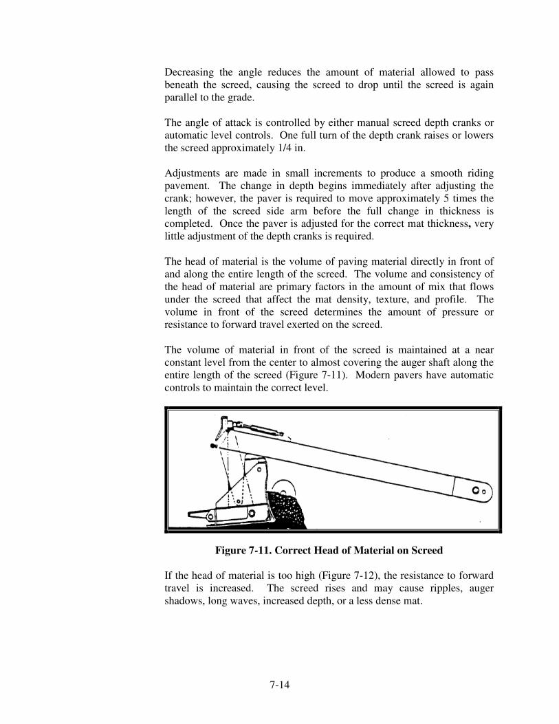
7-14
Decreasing the angle reduces the amount of material allowed to pass
beneath the screed, causing the screed to drop until the screed is again
parallel to the grade.
The angle of attack is controlled by either manual screed depth cranks or
automatic level controls. One full turn of the depth crank raises or lowers
the screed approximately 1/4 in.
Adjustments are made in small increments to produce a smooth riding
pavement. The change in depth begins immediately after adjusting the
crank; however, the paver is required to move approximately 5 times the
length of the screed side arm before the full change in thickness is
completed. Once the paver is adjusted for the correct mat thickness, very
little adjustment of the depth cranks is required.
The head of material is the volume of paving material directly in front of
and along the entire length of the screed. The volume and consistency of
the head of material are primary factors in the amount of mix that flows
under the screed that affect the mat density, texture, and profile. The
volume in front of the screed determines the amount of pressure or
resistance to forward travel exerted on the screed.
The volume of material in front of the screed is maintained at a near
constant level from the center to almost covering the auger shaft along the
entire length of the screed (Figure 7-11). Modern pavers have automatic
controls to maintain the correct level.
Figure 7-11. Correct Head of Material on Screed
If the head of material is too high (Figure 7-12), the resistance to forward
travel is increased. The screed rises and may cause ripples, auger
shadows, long waves, increased depth, or a less dense mat.

7-15
Figure 7-12. Head of Material Too High on Screed
If the head is too low (Figure 7-13), the resistance to forward travel is
decreased and the screed gradually falls, resulting in a thin mat and
possible voids in the mat.
Figure 7-13. Head of Material Too Low on Screed
A fluctuating head of material results in a combination of the mat
deficiencies described above plus alternating changes in the mat texture
and depth.
The speed of the paving operation is determined by the rate of material
delivery to the paver. The optimum speed results in the paver being in
continuous operation, using the mixture as the material is delivered, and
never having trucks stack up waiting to unload. Continuous, uninterrupted
forward travel at a constant speed, with other variables held constant,
produces a smooth riding surface. While absolute compliance with this
goal is usually not possible, fewer interruptions or changes in paving
speed provide a smoother finished surface. The paving speed is required
to be adjusted to give a uniform texture and coordinate with plant
production.
The paving speed to match the plant production may be computed for any
planned quantity. The paving speed and plant production are required to
match and be outlined in the Quality Control Plan.

7-16
Pavers may not operate at speeds in excess of 50 ft per minute for mixes
that are not density controlled by cores. Paver speeds in excess of this
speed often result in non-uniform surfaces.
Whenever the absence of loaded trucks necessitates a pause, the paver is
stopped with a substantial quantity of mix ahead of the screed. Operating
the paver until the mix is too low ahead of the screed results in a dip in the
pavement.
In addition to the three major factors discussed, other improper operating
procedures which may affect the riding quality of the pavement are:
1) Truck bumping the paver -- this practice is the most
common cause of transverse marks and ridges in the
finished mat. Drivers are required to stop their trucks
ahead of the paver and let the paver operator pick up the
truck as the paver travels forward.
2) Truck driver holding brakes -- this practice reduces the
paving speed causing an increase in mat depth and may
cause the paver wheels to slip or break traction. This
problem causes a non-uniform edge line of the mat and a
bump in the mat.
3) Paver engine in poor operating condition -- an improperly
functioning engine may cause power and speed surges
resulting in ripples, waves, or auger shadows in the mat.
4) Unequal or over inflation of paver tires -- this may cause
the drive wheel to slip or break traction resulting in a
rough, uneven mat.
5) Loose or unevenly tensioned traction drive chains -- this
may cause power or speed surges resulting in ripples,
waves, or auger shadows in the mat.
Automatic grade and slope controls are required to be outlined in the QCP
for mixtures produced in accordance with Section 401. Section 402
indicates that automatic slope and grade controls are required except when
placing mixtures on roadway approaches which are less than 200 ft (60 m)
in length or on miscellaneous work. The use of automatic controls on
other courses where the use is impractical due to project conditions may
be waived by the Engineer.

7-17
START-UP
Three types of start-ups are used in hot mix asphalt paving:
1) Full depth
2) Continuing an existing lay
3) Feathering
A full depth start-up is used where paving is started at an intermediate
point in the contract. Before starting, the screed is required to be elevated
from the grade by the thickness of the mat plus an allowance for the
compaction to be achieved by the rolling. Wooden blocks of the required
thickness are placed under each end of the screed.
When continuing from a previously laid mat, the tapered material is
removed back to the full-depth section and the joint lightly tacked. Strips
of lath thick enough to allow for compaction are placed under the ends of
the screed as illustrated in Figure 7-14. The front of the screed should
never be placed beyond the joint.
Figure 7-14. Continuing on Existing Lay
When building a start-up feather joint, the screed is set directly on the
existing pavement at an angle to gradually taper up to the full depth. The
feathering is required to be long enough to provide a smooth transition to
the driving surface. Temporary transverse joints, if constructed under
traffic, are also feathered.
Paving exceptions are indicated on the plans. Bridges, except for earth-
filled arches, are usually an exception from paving. Adding HMA
pavement over a concrete bridge deck would cause deterioration to the
deck. There may be exceptions when paving under a bridge if the added
pavement would reduce the overhead clearance to an unacceptable height.
Vertical clearance requirements are designated in 105.08(b).

7-18
With any start-up, the screed is required to be hot before any mix is
processed through the paver. Screed heaters are provided on all pavers to
preheat the screed. Once the screed is hot, the heaters may be turned off
because the heated mixture keeps the screed hot. Screed extensions bolted
on to the paver to attain the required width are also required to be heated.
The heating device on the main screed does not provide heat to these
extensions.
The front of the screed is required to be set slightly higher than the rear of
the screed to provide what is commonly referred to as the “angle of
attack”. This angle allows the screed to climb enough to equal the amount
of compaction that the screed exerts on the mix. Thickness checks are
made frequently during the start-up to ensure that the screed is set
correctly to produce the desired thickness.
ALIGNMENT
The alignment of the edge of the pavement is critical to the appearance of
the highway. When overlaying an existing pavement with a uniform edge,
the paver operator may use the edge as a guide for laying the new
pavement. When the edge is irregular or the lay is on a new base, an off-
set string line to guide the paver is recommended. The requirement for
good alignment is discussed with the Contractor before starting the paving
operation. Neat lines are a requirement for a good quality pavement.
Another cause of poor alignment is overloading the propulsion capabilities
of the paver. On steep grades, the haul truck may be required to dump
only a portion of the load and pull ahead to take the additional dead load
off the paver. This may also be necessary on fresh tack where the paver is
not maintaining traction. Fishtailing of the paver is usually caused by
overloading, slipping of the crawlers or drive wheels, or steering clutches
in poor condition.
The pointer mounted on the paver is recommended to be rigid rather than
a pendulum type because the rigid type permits more control in following
the string line or pavement edge.
GRADE AND SLOPE CONTROL
The paver may be equipped with an automatic grade and slope device.
The automatic grade device controls the screed to adjust the thickness of
the mat as the mix is placed to meet the desired grade. The automatic
grade device may be guided with a string line, a grade leveler, or a joint
marker, depending on the conditions of the existing pavement.

7-19
The screed may also be controlled by turning the depth crank. Once the
paver is adjusted to the automatic grade device, the depth cranks are not
used. One exception would be if the automatic grade device quit working.
Manual controls may be used if this occurs to place the material in transit,
however, stopping the operation until repairs can be made is
recommended.
The slope meter is used to pre-set the paver to produce the specified cross
slopes for crown and superelevation. The screed is hinged in the middle to
permit crown adjustment at both the leading and trailing edges of the
screed. The leading edge is required to always have slightly more crown
than the trailing edge to provide a smooth flow of material under the
screed. Too much crown produces an open texture along the edges of the
mat. Too little crown results in an open texture in the center.
TRANSVERSE JOINTS
A transverse joint, commonly called a day joint, is normally required at
the end of each day’s paving to provide a smooth transitional ramp for
traffic. One procedure to construct a day joint is indicated in the series of
drawings in Figure 7-15; however, there are other acceptable procedures
for this joint. The procedure for the construction of the transverse joint is
required to be included in the QCP for the project.

7-20
Figure 7-15. Construction of a Day Joint

7-21
The last few feet of the mat is left unrolled, the mix is cleared away from
the wedge area, joint paper is laid on the existing surface and up the
vertical face of the joint, the mix is shoveled over the paper to form the
wedge, and the mat is rolled. The Contractor is not allowed to completely
empty the paver hopper to make the day joint since some of the mix still in
the hopper is too cold. When paving is resumed, the wedge and paper are
removed to provide an exposed mat that is full-depth and at the proper
grade for continuing the lay. The screed is blocked up with wooden strips
as previously described. The paver is positioned with the front of the pre-
heated screed over the joint line. After the hot mixture is conveyed into
place, sufficient time to re-heat the joint is allowed before moving the
paver forward. The paver is advanced enough to allow the workmen to
conduct the necessary handwork. The straightedge is required to be used
to check the joint to ensure the proper grade before allowing the roller on
the surface. Once the joint has been rolled, the joint is rechecked with the
straightedge. If any corrections are required there is sufficient heat
remaining in the mix to make a smooth joint.
LONGITUDINAL JOINTS
Longitudinal joints are made when joining adjacent lays to make the
specified width of pavement. The paver screed does not overlap the
previous lay and is carried slightly higher to allow for compaction of the
new lay to match the previous lay. The raker uses a lute to remove the
excess material from the previous lay into the new lay to obtain a tight,
smooth joint and to prevent the rollers from compacting this material into
the cold mat. The paver attempts to place the material in such a way that
no luting is necessary.
Joint Adhesive
Longitudinal joint performance has been a problem with HMA pavements
because of the difficulty of obtaining a tight joint that will resist the
penetration of water into the pavement. This water will eventually cause
stripping of the underlying layers and deterioration of the joint. A joint
adhesive material placed on the joint (Figure 7-16) would reduce the water
penetration into the joint and improve the joint performance.
When joint adhesive materials are required by RSP 401-R-581, the
material is applied to longitudinal joints constructed in the top course of
dense graded intermediate mixtures and all surface mixture courses. This
includes joints within the traveled way as well as between the traveled
way and an auxiliary lane, the traveled way and a paved shoulder, and an
auxiliary lane and a paved shoulder.

7-22
Figure 7-16. Joint Adhesive
Safety Edge
A safety edge (Figure 7-17) is a wedge of asphalt mixture placed at the
edge of the pavement that results in a 30 - 35° angle of mixture. The
purpose of the safety edge is to provide a means for a vehicle to leave or
access the edge of pavement and therefore reduce roadway departure
accidents. The devices approved for constructing the safety edge are listed
in Section 409.03 (c).
Figure 7-17. Safety Edge

7-23
WIDENING MACHINES
Widening machines (Figure 7-18) are used when the width to be laid is too
narrow or inaccessible for the regular paver. The inside 4 ft wide shoulder
of a dual-lane highway is one example of when HMA may be placed
separately using a widening machine.
Widening machines are required to be self-propelled and capable of
placing material at variable widths. Vibrating or heated screeds and
automatic grade and slope controls are not required for these machines;
however, automatic grade controls for matching joints are available on
some models. The use of widening pavers is not allowed on widths of 8 ft
or more.
Figure 7-18. Widening Machine
Widening machines are equipped with hoppers for receiving the mix from
the haul units, conveyors to carry the mix to either side of the machines,
and adjustable strike-offs on each side of the machine to allow placing on
either side. The strike-off may be adjusted vertically up to 12 in. below or
above the grade, depending on the make and model, to allow placing
material in lifts.
The strike-off blade does not have the compactive capability of the screed
on a regular paver. Consequently, the surface texture is likely to be more
open.

7-24
The proper adjustment of the strike-off blade is the key to obtaining a
good pavement with a widening machine. The settings for the [paver]
machine are checked before the paving operation is started. After paving
a short distance, the mat is required to be checked for the following:
1) Proper width – if correction is necessary, the width is
adjusted by expanding or contracting the strike-off. The
outer edge plate may also need to be readjusted parallel
with the road edge.
2) Proper elevation – adjusted by raising or lowering the inner
strike-offs.
3) Proper slope – adjusted with the outer strike-off support.
The sliding outer edger plate, may also require
readjustment.
4) Inner edger plate – positioned to prevent paving material
from piling up on the existing pavement. The inner edger
plate is adjusted to be parallel to the pavement surface set
in the lowest position.
5) Flow of material - the flow of material in front of and under
the strike-off is watched. Adjustment from the vertical
positions may be required.
If the top of the strike-off is tilted back (Figure 7-19), the plate rolls
material up. Excessive backward tilt forces the strike-off to pull down
into the material.
Figure 7-19. Strike-Off Plate Tilted Back

7-25
Tilting the top of the strike off plate forward (Figure 7-20) causes the
strike-off to roll the material down. Excessive forward tilt forces the
strike-off to ride up over the material.
Figure 7-20. Strike-Off Plate Tilted Forward
CARE AND CLEANING OF PAVERS
Pavers are required to be checked for oil and fuel leaks because petroleum
products damage the mix. Fuel oil, kerosene, or solvents are not allowed
to be transported in open containers on any equipment. Cleaning of
equipment and small tools also is not allowed on the pavement or shoulder
areas.
The paver hopper, conveyors, augers, and screeds are required to be
cleaned at the end of each day. Any hardened mix is removed so the mix
is not contaminated when the paving is resumed.
Caution is used at paver cleanout sites because excessive fuel oil
saturating the ground may lead to pollution problems. The Contractor is
required to clean the areas where the paver is maintained.
PAVING CREW RESPONSIBILITIES
Paver Operators
The paver operator responsibilities include safely operating the paver and
using the paver best practices to produce the highest quality pavement
possible. Specific responsibilities include:
1) Selecting the paving speed that balances delivery, paver
capacity and the compaction process, and paving with few if
any extended stops
2) Working with the screed operator in establishing and
maintaining the head of material within a plus or minus one-
inch tolerance

7-26
3) Steering the paver and holding the paver to a pre-determined
reference
4) Directing the truck driver to raise the bed and exit when empty
5) Utilizing rapid but smooth starting and stopping operations to
help prevent end-of-load roughness
6) Observing the HMA being discharged into the paver hopper or
insert for changes in the characteristics of the mixture
7) Monitoring the paver for unusual noise or vibration
8) Working with the dump person to make sure the truck does not
bump the paver or that the hopper runs low on material
Screed Operator
The screed operator responsibilities include understanding the basic
principles of paving with a free-floating screed and knowing the screed
design, operation, and adjustments. An awareness of HMA mix design
characteristics and what may change if the mixture varies throughout the
day is valuable. Specific responsibilities include:
1) Setting up the screed and paving reference to match the
specification requirements for width, crown, slope, and
depth
2) Heating the screed properly
3) Working closely with the paver operator in establishing and
maintaining the head of material within a plus or minus
one-inch tolerance
4) Operating the grade and slope system, utilizing the
designated references, and occasionally checking that the
mat being laid is being held to the established references
5) Making screed adjustments to produce a consistent textured
mat
6) Following the best practices for making sound longitudinal
and transverse joints

7-27
Lute Person
The lute person (Figure 7-21) responsibilities include assuring that any
mat deficiencies are corrected prior to compaction. Specific
responsibilities include:
1) Hand working any area of the mat which cannot be placed
by the paver
2) Repairing all pavement imperfections
3) Preparing transverse and longitudinal joints for compaction
4) Preparing end-of-pass wedges or tapers for compaction
5) Assisting in cleaning the paver at the end of the shift
6) Assuring the quality of the finished project and
communicating problems to the responsible person when
they arise
Figure 7-21. Luting Transverse Joint

7-28
COMPACTION
ROLLERS
Six types of rollers are used for compacting HMA: two-axle tandem,
three-wheeled, pneumatic tire, vibratory, oscillatory, and trench rollers.
All of the rollers have steel wheels, except for the pneumatic-tire roller
which has rubber wheels.
All rollers are required to have proper sprinkling systems to wet the drums
or tires to prevent the mix from sticking. Scrapers are usually required on
steel-wheel rollers. Rollers are required to be equipped with drip pans to
prevent oil, grease, or fuel from dropping onto the roadway. Clutches are
required to function smoothly. A roller that jerks when starting, stopping,
or reversing causes a rough surface.
QC/QA mixtures in accordance with 401 and SMA mixtures in
accordance with 410 are compacted with rollers determined by the
Contractor. HMA mixtures are required to be compacted by the rollers
designated in 402.15.
Tandem Roller
A tandem steel-wheel roller (Figure 7-22) is required by Section
409.03(d)1 to weigh at least 10 tons.
Figure 7-22. Tandem Roller

7-29
Three Wheel Roller
The three wheel roller (Figure 7-23) is required by Section 409.03(d) 2 to
have a compression or drive rolls that produce a bearing of at least 300
pounds per linear inch of roll width. This bearing weight is computed by
dividing the weight of the drive axle by the combined width of the two
rolls. A tandem roller, which has a drive wheel bearing of no less than
300 pounds per linear inch may be used in lieu of the three wheel roller.
Figure 7-23. Three Wheel Roller
Pneumatic Tire Roller
A pneumatic tire roller (Figure 7-24) is required by Section 409.03(d) 3 to:
1) Be self propelled
2) Have a minimum width of 5 ft 6 in.
3) Be equipped with compaction tires, with a minimum size of
7:50 by 15
4) Be capable of exerting a uniform, average contact pressure
from 50 to 90 pounds per square inch over the surface by
adjusting ballast and tire pressure
5) Have wheels on at least one axle that are fully oscillating
vertically and so mounted so as to prevent scuffing of the
surface during rolling or turning

7-30
Figure 7-24. Pneumatic Tire Roller
The tires on a pneumatic tire roller are typically arranged so the gaps
between the tires on one axle are covered by the tires of the other as
shown in Figure 7-25.
Figure 7-25. Pneumatic Tire Alignment
The Contractor is required to furnish charts and tabulations indicating the
contact areas and pressures for the full range of tire inflation pressures and
for the full range of tire loadings for each type and size of pneumatic tire
roller to be used.
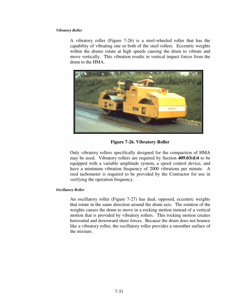
7-31
Vibratory Roller
A vibratory roller (Figure 7-26) is a steel-wheeled roller that has the
capability of vibrating one or both of the steel rollers. Eccentric weights
within the drums rotate at high speeds causing the drum to vibrate and
move vertically. This vibration results in vertical impact forces from the
drum to the HMA.
Figure 7-26. Vibratory Roller
Only vibratory rollers specifically designed for the compaction of HMA
may be used. Vibratory rollers are required by Section 409.03(d)4 to be
equipped with a variable amplitude system, a speed control device, and
have a minimum vibration frequency of 2000 vibrations per minute. A
reed tachometer is required to be provided by the Contractor for use in
verifying the operation frequency.
Oscillatory Roller
An oscillatory roller (Figure 7-27) has dual, opposed, eccentric weights
that rotate in the same direction around the drum axis. The rotation of the
weights causes the drum to move in a rocking motion instead of a vertical
motion that is provided by vibratory rollers. This rocking motion creates
horizontal and downward sheer forces. Because the drum does not bounce
like a vibratory roller, the oscillatory roller provides a smoother surface of
the mixture.

7-32
WeightWeight
Figure 7-27. Oscillatory Roller
Trench Roller
When the width of a trench is too narrow to accommodate a standard
roller, a trench roller (Figure 7-28) is used for compaction. The trench
roller is required by Section 409.03(d)6 to be of sufficient weight to exert
a pressure of 300 pounds per linear inch of width for the compression
wheel. The compression wheel may be either hollow or solid. Weight is
added to hollow wheels by filling the wheel with water ballast. Counter-
weights are used for rollers with solid wheels.
To provide uniform compaction for the entire width of the compression
wheel, the face of the wheel is required to be parallel to the surface being
compacted. Trench rollers use a vertical adjustment on the wheel not in
the trench to tilt the machine to accomplish this uniform compaction.
Figure 7-28. Trench Roller

7-33
COMPACTION OF HMA
Compaction of HMA mixes is conducted with steel wheel, pneumatic
tired, vibratory, or oscillatory rollers in three phases:
1) Breakdown or initial rolling
2) Intermediate rolling
3) Finish rolling
Both vibratory and tamper-type paver screeds begin the compaction of the
mix as the material flows under the screed. Breakdown rolling compacts
the material beyond that imparted by the paver, intermediate rolling
compacts and seals the surface, and finish rolling removes the roller marks
and other blemishes left from the previous rolling.
Breakdown Rolling
When a single lane is being placed, the outside edge (the low side) of the
lane is rolled first. When placing a new mat adjacent to the existing lay,
the longitudinal joint is rolled first followed by the breakdown rolling on
the low edge.
In general, the roller proceeds straight into the un-compacted mix and
returns in the same path, however, when the roller stops and reverses
direction the roller should be at an angle to the pavement. The turning
movement is normally completed on previously compacted material. The
drive wheel of the roller is toward the paver because there is less tendency
for the mix to shove under the drive wheel. The recommended pattern for
breakdown rolling is illustrated in Figure 7-29.
Figure 7-29. Breakdown Rolling Pattern

7-34
After the required passes for the breakdown rolling are completed, the
roller is moved to the outside of the lane on the cooled portion of the mat
to repeat the process on the next segment.
Intermediate Rolling
Intermediate rolling is conducted immediately after the breakdown rolling
while the mix is still hot and at a temperature that results in maximum
density. The rolling pattern is the same pattern as done for the breakdown
rolling.
Keeping the tires hot helps prevent the newly laid material from sticking
to the tires for the pneumatic-tired roller. Intermediate rolling is
continuous until compaction is attained. If the mixture is accepted in
accordance with Section 402, the rolling pattern is established by the
specifications.
Final Rolling
Final rolling is conducted to improve the surface texture. This rolling is
completed while the mat is still warm enough so roller marks from the
breakdown and intermediate compaction are removed.
SPECIFIED ROLLERS
Compaction may be controlled by the number of passes of a specified
series of rollers (Section 402) or by density (Section 401 and 410). The
QCP for the contract is required to specify the type of rollers to be used.
Sufficient rollers are required to be operated to complete the compaction
before the temperature of the mix has cooled to a point where the density
cannot be obtained.
The rolling operation is required to obtain a fully compacted mat. If the
necessary compaction is not attained, subsequent traffic may consolidate
the mat further resulting in wheel ruts. Some mixtures, designated as
“tender mixtures”, may have a temperature range whereby after the initial
breakdown passes, rolling is required to cease until the temperature drops
to an acceptable level. Otherwise, the mat may be damaged and/or any
density attained by initial breakdown may be lost. Monitoring compaction
during the first day of paving is critical to obtain the necessary density.
Section 402.15 for non-QC/QA mixtures allows the Contractor to
designate the type of rollers used. Option No. 1 requires a three wheel
roller, followed by a pneumatic tire roller and a tandem roller. Options 2,
3, 4, and 5 include different roller and roller application combinations. A
roller pass is defined as one pass of the roller over the entire mat. The
various options for rolling are included in the following table.

7-35
Number of Roller Applications
Rollers
Courses ≤ 440 lb/yd2
Courses >
440 lb/yd2
Option
1
Option
2
Option
3
Option
4
Option
5
Option
1
Option
2
Three
Wheel 2 4
4
Pneumatic
Tire 2 4
4
Tandem 2 2 2
4
Vibratory 6
8
Oscillatory
6 -- --
PLANT PRODUCTION - NUMBER OF ROLLERS
Before the contract begins, verification that there are a sufficient number
of rollers and haul trucks to keep pace with the anticipated plant
production is necessary. This procedure is documented in the Quality
Control Plan required for the project.
COMPACTION CONTROLLED BY DENSITY
For all QC/QA (401) and SMA (410) mixtures, density is determined by
cores obtained from the mat after all rolling is complete except for the
following locations:
1. The total planned lay rate to be placed over a shoulder existing
prior to the contract is less than 385 lb/yd2
2. The first lift of material placed at less than 385 lb/yd2 over a
shoulder existing prior to the contract award
If cold weather paving is allowed, the density is also determined by cores
(Section 402.16).
Quality control procedures for density control are to be included in the
QCP in accordance with ITM 803. Non-destructive density testing is
required except for cores taken to correlate the density gauge and quality
control cores defined in the QCP. Nuclear or non-nuclear gauges may be
used. Each gauge is calibrated in accordance with the manufacturer’s
recommendations and correlated to the type of mixture being placed,
depth of mixture, and possibly the underlying base materials. Near the
beginning of the paving operation, an area may be designated for testing to
determine the proper rolling patterns to achieve the target density. This
area is commonly referred to as a "test strip". Non-destructive tests are
taken and cores obtained at the same locations in the test strip. The

7-36
difference between the gauge readings and the measured core densities is
determined and used for an "offset" for the gauge.
For Non-QC/QA mixtures, the density is controlled by the specified
rolling option (Section 402.15).
WIDENING
HMA mixtures placed as widening and other depressed areas may be
rolled with a trench roller.
ROLLING PATTERNS
Rolling of HMA mixtures may vary depending on the conditions on the
project. In general, the best practice for the sequence of the rolling
operations is the following:
1) Transverse joints
2) Begin the initial or breakdown rolling at the low side and
proceed to the high side of the mat
3) Longitudinal joints – if the new mat is adjoining a
previously placed lane
4) Intermediate rolling
5) Finish rolling
Any area that cannot be compacted by rollers is required to be compacted
with hand tampers, plate vibrators, or other approved equipment.
Rollers, regardless of the type, are not allowed to be parked on the fresh
mat.
Transverse Joints
The ramp section and paper from the day joint are required to be removed
prior to starting paving. The screed is set enough higher than the
previously laid mat to allow for compaction. When the paver has moved
away from the joint, any mix on the surface of the old mat is butted into
the joint with a lute. The joint is first rolled transversely with the roller
compacting on the old mat and extending into the uncompacted mix about
6 in. Pinching the material into the joint in this way helps attain a tight
joint. Planks perpendicular to the lay are used to support the roller to
prevent breaking down the edge of the mat while rolling in the transverse
direction. Rolling is continued transversely until about 3 ft of the new lay
has been rolled.

7-37
The roller is then turned parallel to the laydown and rolling is continued.
The joint is required to be checked with a straightedge. The roller usually
smooths out a bump while the mix is still warm by rolling transversely.
Additional material may be required if the straightedge indicates a dip.
Material may be added by hand, leveled with a lute, and then re-rolled to
correct a dip. However, adding material tends to produce poorer quality
surface texture.
Longitudinal Joints
Section 402 requires that the longitudinal joint be compacted in
accordance with the following:
1) For confined edges, the first pass adjacent to the confined
edge, the compaction equipment shall be entirely on the hot
mat 6 in. from the confined edge
2) For unconfined edges, the compaction equipment shall
extend 6 in. beyond the edge of the hot mat
Another technique for the construction and compaction of the
longitudinal joint that may be used for mixtures placed in
accordance with Sections 401 and 410 is illustrated in Figure 7-29
and explained as follows:
1) The uncompacted HMA abutting a cold mat is placed 1/4
in. per 110 lb/yd2 higher than the cold mat. Any HMA
placed on top of the cold mat is required to be removed
from the cold mat prior to compaction.
2) The first pass of the breakdown roller to the paver and the
return pass from the paver are required to overlap an
unconfined edge or cold mat by 6 in.
3) The entire width of the mat is required to receive a uniform
number of passes of the compaction equipment. If the mat
is tender with pushing and shoving during the compaction
operation, the rolling operation is required to be delayed
until the mat becomes stable under the roller.

7-38
1
2
3
4
Figure 7-29. Longitudinal Joint Compaction
ROLLER DRUM
(6 in.)
COLD MAT HOT MAT
1/4 in. per 110 lb/yd2
Minimum Overlap
COLD MAT HOT MAT
Remove or lute off any
overlapping material.
COLD MAT
ROLLER DRUM
HOT MAT
6 in.

7-39
The notched wedge longitudinal construction joints (Figure 7-30) is
another procedure used for constructing the longitudinal joint. This type
of joint has shown the potential of improving the construction of
longitudinal joints by providing better compaction at the joint.
Lift thickness
Figure 7-30. Notched Wedge Longitudinal Construction Joint
Joint adhesive materials are also being used for the purpose of sealing
construction joints formed between adjacent HMA pavement courses
(Figure 7-31). The joint adhesive is applied to longitudinal joints
constructed in the top course of dense graded intermediate mixtures and
all surface mixture courses. This includes joints within the traveled way
as well joints between the traveled way and an auxiliary lane, joints
between the traveled way and a paved shoulder, and joints between an
auxiliary lane and a paved shoulder.
Figure 7-31. Joint Adhesive Material
0.50 in.
12 in.

7-40
ROLLER OPERATOR RESPONSIBILITIES
Breakdown and Intermediate Roller Responsibilities
The breakdown and intermediate roller operator responsibilities for
vibratory rollers include obtaining pavement density while the HMA is in
the proper temperature range for compaction without risking aggregate
damage. Rolling with the vibration toward the paver and establishing the
rolling pattern with the fewest side-by-side passes as possible is required.
Also, controlling the roller speed to provide proper drum impact, keeping
up with the paver, and operating in the best temperature zone are
additional responsibilities. If one roller cannot maintain the production
rate, a second breakdown roller will be needed. Specific responsibilities
include:
1) Communicating with the paving crew and foreman for the
project requirements prior to arrival of the HMA
2) Doing daily maintenance on the roller and checking the
water system
3) Determining the lift thickness
4) Being aware of the material temperature at delivery to the
paver and behind the screed
5) Determining if the rolling drum mode is vibratory or static
depending on the requirements to achieve density
6) Making the required amplitude adjustments for both drums
for the mix design, material thickness, and the temperature
zone
7) Optimizing the water system controls to avoid material
pick-up and eliminate excessive water usage
8) Establishing the proper rolling pattern considering the
paving width, roller drum width, unsupported edges, and
drum overlap
9) Determining rolling speed to achieve the proper impact
spacing and smoothness requirements
10) Monitoring rolling temperature and working with the
optimum temperature zones
11) Recognizing tender mixtures and adjusting the roller
pattern

7-41
12) Making the required rolling coverage to achieve density
requirements
13) Adjusting rolling operations to satisfy the density,
smoothness, and production rates
14) Maintaining consistency throughout the entire working
shift
Finish Roller Responsibilities
The finish roller operator responsibilities include removing all surface
marks and blemishes from the finished pavement. The operator may be
required to achieve final compaction in some cases where breakdown and
intermediate rolling have not achieved the target density. Rolling at the
necessary speed to maintain production is required and using vibration is
rarely done. Specific responsibilities include:
1) Communicating with the paving crew, foreman and
breakdown operator for the project requirements
2) Confirming maintenance and water system checks on a
daily basis
3) Being aware of the material temperature and avoiding the
tender zone
4) Determining if the rolling mode is vibratory or static
depending on the requirements to achieve density and
smoothness
5) Optimizing the water system controls to avoid pick-up and
eliminate excessive water usage
6) Establishing the proper rolling pattern determined by the
paving width, rolling drum width, unsupported edges, and
drum overlap
7) Coordinating the final rolling process with QC personnel
8) Monitoring the rolling temperature and working within the
optimum temperature zones
9) Making the required rolling coverage to achieve density
requirements and to remove drum edge marks
10) Maintaining consistency throughout the entire working
shift

8 Paving Troubleshooting
Problems Observed of the Mixture in the Trucks Free Asphalt on Mix
Free Dust on Mix
Large Aggregate Uncoated
Mixture Not Uniform
Mixture Fat on One Side
Mixture Flattens
Mixture Burned
Mixture Brown or Gray
Mixture Too Fat
Mixture Smokes
Mixture Steams
Mixture Appears Dull
Problems Observed During Paving Bleeding
Transverse Joints – Improper Elevation Across Joint
Transverse Joints – Rough Uneven Joint
Screed Marks
Surface Texture Fluctuation
Tearing of Mat – Full Width
Tearing of Mat – Center
Tearing of Mat – Edge
Thickness and Mat Quality Variations
Wavy Surface – Long Waves
Wavy Surface – Ripples, Short Waves

Problems Observed During Compaction Checking Under Roller
Mat Shoving Ahead of Roller
Roller Marks
Unsatisfactory Compaction

8-1
CHAPTER EIGHT:
PAVING TROUBLESHOOTING
Long-term pavement performance is the result of the smoothness and mat
quality of the HMA mixture. Smoothness affects the transportation costs
of the road user to include vehicle maintenance coasts, fuel consumption,
speed, passenger comfort, safety, and vehicle noise. Poor mat quality also
affects the pavement performance and may be caused by cracks,
segregation, poor joints, and other defects. Furthermore, low density may
cause the mix to deform, make the mix more susceptible to moisture,
prematurely harden the asphalt, decrease the fatigue resistance, or reduce
the structural strength of the pavement.
This chapter will discuss the problems that affect the smoothness and
quality of the pavement mat and the possible solutions for correcting these
deficiencies. Problems may be detected by observing the mixture in the
truck or Material Transfer Vehicle (MTV) during the transfer of the
mixture to the paver, by observing the mixture after the paving operations,
and by observing the mixture during the compaction process.
____________________________________________________________
PROBLEMS OBSERVED OF THE MIXTURE IN THE TRUCKS
As the HMA is transferred to the paver from the truck or MTV, the
operator should observe the mixture for any obvious problems. Problems
may be caused by the mixture materials or operations of the plant. The
following discussion lists the more common problems observed of the
mixture in the trucks or MTV, the type of plant associated with the
problem, and the causes of the problems.

8-2
FREE ASPHALT ON MIX
Batch and Drum Plants
1. Too much asphalt
2. Faulty distribution of asphalt to aggregates
Batch Plant
1. Aggregate scales out of adjustment
2. Improper weighing
3. Asphalt scales out of adjustment
4. Undersize or oversize batch
5. Improperly set or worn paddles
Drum Plant
1. Asphalt meter out of adjustment
2. Asphalt and aggregate feed not synchronized
FREE DUST ON MIX
Batch Plant
1. Improper weighing sequence
2. Faulty dump gate
LARGE AGGREGATE UNCOATED
Batch and Drum Plants
1. Insufficient asphalt
2. Faulty distribution of asphalt to aggregates
3. Irregular plant operation
Batch Plant
1. Asphalt scales out of adjustment
2. Undersize or oversize batch
3. Mixing time not proper
4. Improperly set or worn paddles
Drum Plant
1. Asphalt meter out of adjustment
2. Asphalt and aggregate feed not synchronized

8-3
MIXTURE NOT UNIFORM (FIGURE 8-1)
Figure 8-1. End of Truck Segregation
Batch and Drum Plants
1. Leaky Bins
2. Segregation of aggregates in bins
3. Carryover in bins due to overloading screens
4. Insufficient aggregates in hot bins
5. Faulty distribution of asphalt to aggregates
6. Irregular plant operation
Batch Plant
1. Faulty screen operation
2. Bin overflows not functioning
3. Aggregate scales out of adjustment
4. Improper weighing
5. Feed of mineral filler not uniform
6. Improper weighing sequence
7. Asphalt scales out of adjustment
8. Mixing time not proper
9. Improperly set or worn paddles
10. Faulty dump gate
11. Occasional dust shakedown in bins
Drum Plant
1. Asphalt meter out of adjustment
2. Irregular plant operation

8-4
MIXTURE FAT ON ONE SIDE
Batch and Drum Plants
1. Faulty distribution of asphalt to aggregates
2. Irregular plant operation
Batch Plant
1. Improper weighing
2. Undersize or oversize batch
3. Mixing time not proper
4. Improperly set or worn paddles
MIXTURE FLATTENS
Batch and Drum Plants
1. Too much asphalt
2. Faulty distribution of asphalt to aggregates
3. Irregular plant operation
Batch Plant
1. Aggregate scales out of adjustment
2. Undersize or oversize batch
Drum Plant
1. Asphalt meter out of adjustment
2. Asphalt and aggregate feed not synchronized
MIXTURE BURNED
Batch and Drum Plants
1. Aggregate feed gates not properly set
2. Improper dryer operation
3. Temperature indicator out of adjustment
4. Aggregate temperature too high
5. Irregular plant operation

8-5
MIXTURE BROWN OR GRAY
Batch and Drum Plants
1. Aggregates too wet
2. Over-rated dryer capacity
3. Dryer set too steep
4. Improper dryer operation
5. Temperature indicator out of adjustment
6. Insufficient asphalt
7. Irregular plant operation
Batch Plant
1. Faulty screen operation
Drum Plant
1. Asphalt meter out of adjustment
2. Asphalt and aggregate feed not synchronized
MIXTURE TOO FAT
Batch and Drum Plants
1. Insufficient aggregates in hot bins
2. Too much asphalt
3. Faulty distribution of asphalt to aggregates
4. Irregular plant operation
Batch Plant
1. Aggregate scales out of adjustment
2. Improper weighing
3. Feed of mineral filler not uniform
4. Asphalt scales out of adjustment
5. Undersize or oversize batch
Drum Plant
1. Asphalt meter out of adjustment
2. Asphalt and aggregate feed not synchronized
MIXTURE SMOKES
Batch and Drum Plants
1. Improper dryer operation
2. Temperature indicator out of adjustment
3. Aggregate temperature too high
4. Irregular plant operation

8-6
MIXTURE STEAMS
Batch and Drum Plants
1. Aggregates too wet
2. Over-rated dryer capacity
3. Dryer set too steep
4. Improper dryer operation
5. Temperature indicator out of adjustment
6. Irregular plant operation
MIXTURE APPEARS DULL
Batch and Drum Plants
1. Improper dryer operation
2. Temperature indicator out of adjustment
3. Aggregate temperature too high
PROBLEMS OBSERVED DURING PAVING
During the paving operations, the paving crew should observe the mixture
behind the screed prior to compaction for obvious problems. Problems
may be caused by mix designs, plant operations, existing pavement
conditions, or operations of the paver. The following discussion lists the
more common problems, the probable causes, and possible solutions.

8-7
BLEEDING (FIGURE 8-2)
Figure 8-2. Bleeding
Probable Cause-Possible Solution
1. Prime or tack coat too heavy (Figure 8-3)
a. Use correct prime or tack coat application rates
Figure 8-3. Tack Too Heavy
2. Poor prime penetration
a. If granular base is too moist, allow drying period or re-work
base material
3. Segregation of HMA
a. Can be due to many factors including materials handling, mix
gradation, operation and condition of storage bins, paver
operations, etc.
4. Moisture

8-8
TRANSVERSE JOINTS – IMPROPER ELEVATION ACROSS JOINT
Probable Cause-Possible Solution
1. Differential compaction
a. Set screed on blocks
b. Allow for compaction of about ¼ in. per 1 in. layer thickness
2. Poor joint preparation
a. Remove tapered area from previous paving
b. Prepare well-defined vertical face
TRANSVERSE JOINTS – ROUGH UNEVEN JOINT
Probable Cause-Possible Solution
1. Poor compaction technique
a. Roll joint transversely
b. Use correct compaction technique
2. Poor raking technique or excessive raking (Figure 8-4)
a. Minimize raking
b. Trim and remove any excess from cold side of joint
Figure 8-4. Poor Raking at Joint
3. Segregation of HMA at mat edge
a. Can be due to many factors including materials handling, mix
gradation, operation and condition of storage bins, paver
operations, etc.

8-9
SCREED MARKS (FIGURE 8-5)
Figure 8-5. Screed Marks
Probable Cause – Possible Solution
1. Thickness control screws in poor mechanical condition
a. Replace control screws
2. Variable material level in front of screed
a. Adjust hopper gates and/or feed conveyor/spreading screw
speeds
b. Adjust depth sensor
3. Improper operation of paver
a. Use proper paving procedures
b. Release brakes on truck
4. Truck bumps paver or is not square with paver (Figure 8-6)
a. Allow paver to approach truck
b. Make sure all rear wheels of truck are in contact with roller
bar on paver
Figure 8-6. Marks Due to Truck Bumping Paver

8-10
5. Over-sensitive automatic controls or tender mix
a. Check mix proportions and aggregate quality
b. Revise design if excess sand, low filler content, or high
asphalt content
c. Check and correct if moisture in mix
d. Check asphalt grade and temperature-viscosity characteristics
6. Excessive play in screed mechanical connection
a. See operation and maintenance manual
SURFACE TEXTURE FLUCTUATION
Probable Cause – Possible Solution
1. Too much raking and sanding behind machine
a. Use proper raking procedure
2. Variable HMA quality
a. Check mix proportions and sampling procedures
b. Correct at mixing plant
3. Poor temperature control of HMA
a. Correct temperature at mixing plant according to asphalt
temperature-viscosity characteristics
b. Cover load during hauling and waiting
4. Poor asphalt quality
a. Check for asphalt overheating
b. Check with asphalt supplier
c. Test asphalt properties
5. Segregation of HMA
a. Could be due to many factors including stockpiling
procedures, mix gradation, operation and condition of storage
bins, paver operations, etc.
6. Stone size too large for layer thickness
a. Reduce stone size to maximum of one-half of layer thickness
b. Revise mix design
7. Worn screed plates - stone degradation
a. Replace screed plates
b. Check stone quality and rolling techniques
c. Mix too coarse or too cold
8. Variable forward speed of paver
a. Maintain constant forward speed

8-11
TEARING OF MAT – FULL WIDTH (FIGURE 8-7)
Figure 8-7. Mat Tearing Full Width
Probable Cause – Possible Solution
1. Stone size too large for layer thickness
a. Reduce stone size to a maximum of half of the layer thickness
b. Revise mix design
2. Tender Mix
a. Check mix proportions
b. Revise design if excess sand, low filler content, or high
asphalt content
c. Check and correct if moisture in mix
d. Check asphalt grade and temperature-viscosity characteristics
3. Forward speed of paver too fast
a. Reduce paver speed
4. Worn out screed plate
a. Replace screed plate
5. Mix too dry or too harsh
a. Check if mix may be too coarse or aggregates too dirty
b. Increase VMA and asphalt content
c. Consider addition of natural sand

8-12
6. Mix temperature too low
a. Increase mix temperature at plant according to temperature-
viscosity characteristics or in accordance with asphalt supplier
recommendations
b. Cover load during hauling and waiting
7. Rapid cooling of mat surface
a. Check air temperature and wind chill effects
b. Increase number of rollers
c. Reduce forward speed of paver
8. Cold paver speed
a. Heat screed
TEARING OF MAT – CENTER (FIGURE 8-8)
Figure 8-8. Tearing of Mat – Center
Probable Cause – Possible Solution
1. Not enough lead crown
a. Increase lead crown
2. Mix temperature too low
a. Increase mix temperature at plant according to temperature-
viscosity characteristics or in accordance with asphalt supplier
recommendations
b. Cover load during hauling and waiting
3. Worn screed plate
a. Replace screed plate
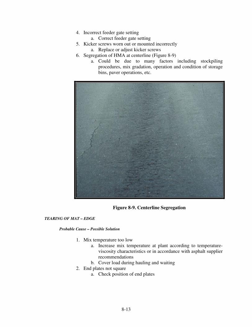
8-13
4. Incorrect feeder gate setting
a. Correct feeder gate setting
5. Kicker screws worn out or mounted incorrectly
a. Replace or adjust kicker screws
6. Segregation of HMA at centerline (Figure 8-9)
a. Could be due to many factors including stockpiling
procedures, mix gradation, operation and condition of storage
bins, paver operations, etc.
Figure 8-9. Centerline Segregation
TEARING OF MAT – EDGE
Probable Cause – Possible Solution
1. Mix temperature too low
a. Increase mix temperature at plant according to temperature-
viscosity characteristics or in accordance with asphalt supplier
recommendations
b. Cover load during hauling and waiting
2. End plates not square
a. Check position of end plates

8-14
3. Too much lead crown in screed
a. Reduce lead crown
b. Check for improper strike-off position
4. Worn screed plate
a. Replace screed plate
5. Excessive overlap
a. Ensure no more than 3 in. overlap
6. Cold Screed
a. Heat screed
7. Incorrect feeder gate setting
a. Correct feeder gate setting
8. Screed extensions installed incorrectly
a. Refer to manufacturer’s manual for correct installation
9. Segregation of HMA at mat edge
a. Could be due to many factors including stockpiling
procedures, mix gradation, operation and condition of storage
bins, paver operations, etc.
THICKNESS AND MAT QUALITY VARIATIONS
Probable Cause – Possible Solution
1. Poor control of material in front of screed
a. Adjust hopper gates and/or conveyer/spreading screw speed
b. Check location and operation of feed sensors to ensure
consistent auger and feeder spread
2. Screed pull point set at improper height
a. Raise screed pull point. Check line of pull (draw line from
bottom of tow point cylinder to pivot point of screed) and
check that this line is parallel with grade
3. Improper operation of paver
a. Use proper procedures
4. Out-of specification HMA
a. Check mix proportions and sampling procedures
b. Correct at mixing facility
5. Poor temperature control
a. Correct at mix plant according to temperature-viscosity
characteristics or in accordance with asphalt supplier
recommendations
b. Cover load during hauling and waiting
c. Consider remixing material at paving site if temperature
differential is more than 25°F across width of mat behind
screed

8-15
6. Poor asphalt content control
a. Evaluate sampling and testing procedures
b. Use Quality Control charts
c. Check asphalt meters or weigh buckets
d. Check belt scales
7. Over-controlling of screed
a. Adjust automatic controls to more closely meet mat thickness
b. Make sure automatics are adjusted to correct sensitivity as
recommended by manufacturer
c. Check for smooth uniform movement of tow point cylinders
8. Unstable or tender HMA (Figure 8-10)
a. Check mix proportions and aggregate quality
b. Revise design if excess sand, low filler content, or high
asphalt content
c. Check and correct if moisture in mix
d. Check asphalt grade and temperature-viscosity characteristics
Figure 8-10. Unstable HMA
9. Poorly graded surface of base
a. Use proper base preparation
b. Use stringline or laser reference for grade control
c. Use longer averaging ski or an inline-averaging ski if grade is
unacceptable outside of paver end gates
10. Hydraulic screed lift is not released
a. Release hydraulics
b. Check for improper or impaired operation of hydraulics

8-16
11. Yielding underlayer – granular bases (Figure 8-11)
a. Improve or modify
b. Check density
c. Do not lay HMA over a saturated base
d. Check drainage
Figure 8-11. Yielding Granular Base
12. Yielding underlayer – overlays
a. Cut out and patch weak areas
b. Maintain constant forward speed
c. Match paver speed to plant output
13. Material on existing pavement (Figure 8-12)
Figure 8-12. Dumped Material on Pavement

8-17
WAVY SURFACE – LONG WAVES
Probable Cause – Possible Solution
1. Poor temperature control of HMA
a. Correct temperature at mixing plant according to asphalt
temperature-viscosity characteristics
b. Cover load during hauling and waiting
2. Over-controlling screed
a. Adjust automatics to match mat thickness
3. Brakes set on truck
a. Release brakes
4. Hydraulic screed lift not released
a. Release hydraulics
b. Check for improper or impaired operation of hydraulics
5. Variable material level in front of screed (Figure 8-13)
a. Adjust hopper gates and/or feed conveyor/spreading screw
speed
b. Adjust depth sensor
Figure 8-13. Auger Material Too Low
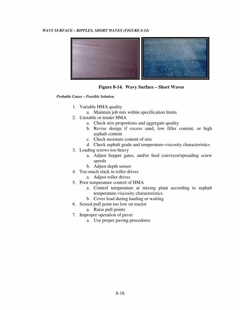
8-18
WAVY SURFACE – RIPPLES, SHORT WAVES (FIGURE 8-14)
Figure 8-14. Wavy Surface – Short Waves
Probable Cause – Possible Solution
1. Variable HMA quality
a. Maintain job mix within specification limits
2. Unstable or tender HMA
a. Check mix proportions and aggregate quality
b. Revise design if excess sand, low filler content, or high
asphalt content
c. Check moisture content of mix
d. Check asphalt grade and temperature-viscosity characteristics
3. Loading screws too heavy
a. Adjust hopper gates, and/or feed conveyor/spreading screw
speeds
b. Adjust depth sensor
4. Too much slack in roller drives
a. Adjust roller drives
5. Poor temperature control of HMA
a. Control temperature at mixing plant according to asphalt
temperature-viscosity characteristics
b. Cover load during hauling or waiting
6. Screed pull point too low on tractor
a. Raise pull points
7. Improper operation of paver
a. Use proper paving procedures

8-19
PROBLEMS OBSERVED DURING COMPACTION
CHECKING UNDER ROLLER (FIGURE. 8-15)
Figure 8-15. Checking Under Roller
Probable Cause – Possible Solution
1. Yielding underlayer – granular bases
a. Check density
b. Do not lay HMA over a saturated base
c. Check drainage
2. Yielding underlayer – overlays
a. Cut out and patch weak areas
3. Tender mix
a. Check mix proportions and aggregate quality
b. Revise design if excess sand, low filler content, or high
asphalt content
c. Check and correct if moisture is in mix
d. Check asphalt grade and temperature-viscosity characteristics
e. Change position of roller in the pattern (vibratory to
intermediate, static to breakdown, etc.)
4. Poor asphalt quality
a. Check that asphalt has not been overheated or contaminated
with harder grade
b. Check with supplier
c. Test asphalt properties
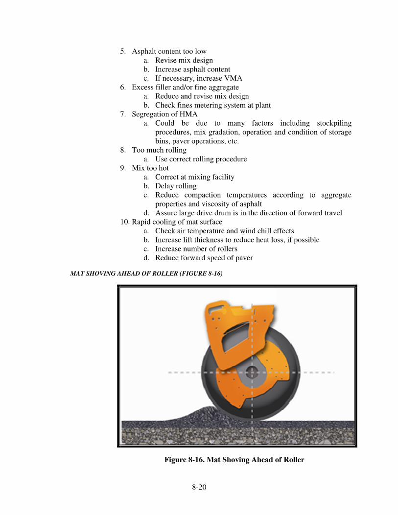
8-20
5. Asphalt content too low
a. Revise mix design
b. Increase asphalt content
c. If necessary, increase VMA
6. Excess filler and/or fine aggregate
a. Reduce and revise mix design
b. Check fines metering system at plant
7. Segregation of HMA
a. Could be due to many factors including stockpiling
procedures, mix gradation, operation and condition of storage
bins, paver operations, etc.
8. Too much rolling
a. Use correct rolling procedure
9. Mix too hot
a. Correct at mixing facility
b. Delay rolling
c. Reduce compaction temperatures according to aggregate
properties and viscosity of asphalt
d. Assure large drive drum is in the direction of forward travel
10. Rapid cooling of mat surface
a. Check air temperature and wind chill effects
b. Increase lift thickness to reduce heat loss, if possible
c. Increase number of rollers
d. Reduce forward speed of paver
MAT SHOVING AHEAD OF ROLLER (FIGURE 8-16)
Figure 8-16. Mat Shoving Ahead of Roller

8-21
Probable Cause – Possible Solution
1. Roller reversing or turning too abruptly
a. Gradually slow and reverse
b. Make wide radius turns
2. Tire pressure of rubber tire roller too high
a. Reduce tire pressures
3. Roller on fresh surface too soon
a. Delay rolling
b. Reduce compaction temperatures according to aggregate
properties and viscosity of asphalt
4. Asphalt content too high
a. Revise mix design
b. If necessary, reduce VMA
5. Yielding underlayer – granular bases
a. Check density
b. Do not lay HMA over a saturated base
c. Check drainage
6. Yielding underlayer – overlays
a. Cut out and patch weak area
7. Aggregate gradation
a. Check mix proportions
b. Reduce fines and uncrushed aggregates
8. Moisture in mix
a. Reduce moisture in material stockpiles, if possible
b. Increase proper drying time
9. Dusty or dirty base
a. Clean with motorized broom
10. Mix temperature too high
a. Reduce at mixing facility according to asphalt temperature-
viscosity characteristics or in accordance with asphalt
supplier’s recommendations
11. Un-combusted fuel in mix
a. Ensure fuel is at correct viscosity for burning
b. Ensure that there is not too little or too much excess air
c. Inspect and, if necessary, adjust burner
d. Check fuel quality
12. Poor asphalt cement quality
a. Check asphalt temperature for overheating
b. Test asphalt properties
13. Moisture accumulation due to condensation
a. Check mix design temperature and storage time in surge bins
14. Tender zone
a. Check temperature ranges for tender zone
b. Compact above or below tender zone
15. Excessive mat thickness relative to aggregate size
a. Reduce individual lift thicknesses, if possible

8-22
16. Incorrect amplitude or frequency settings
a. Adjust according to actual site conditions
17. Prime or tack coat too heavy or too light (Figure 8-17)
a. Use correct application rates
b. Check sprayer calibration
Figure 8-17. Incorrect Tack Coats
ROLLER MARKS
Probable Cause – Possible Solution
1. Tender mix
a. Check mix proportions and aggregate quality
b. Revise design if excess sand, low filler content, or high
asphalt content
c. Check and correct if excess moisture in mix
d. Check asphalt grade and temperature-viscosity characteristics
e. Check temperature ranges for tender zone.
f. Compact above or below tender zone
2. Bump/indentation due to reversing or turning roller too abruptly
a. Gradually slow and reverse
b. Make wide radius turns especially for vibratory rollers
c. Shut off vibration of vibratory roller before reaching the end
of the rolling zone
d. Run straight in and out on successive passes and not make
wide radius turns on hot HMA
e. Stop rollers at an angle (Figure 8-18)

8-23
Figure 8-18. Stopping Roller at an Angle
3. Bump/indentation caused by faulty drive system
a. Check complete drive system of roller including hydrostatic
pumps and motors
4. Edge marks from weight shift when rolling superelevated curve
a. Roll uphill. Start at bottom of superelevation and roll into
elevation, picking up the overlap on successive passes
5. Rough, uneven pavement due to material pick-up on pneumatic,
rollers
a. Allow mix to cool and tires to reach mat temperature
6. Rough, uneven pavement due to material pick-up on steel or vibratory
steel rollers
a. Ensure water spray nozzles operating and the water tank is full
b. Properly adjust rubber scrappers, cocoa mats, and steel
scrapers
7. Bump/indentation from parked roller
a. Don’t park roller on mat or vibrate drum when roller is
stationary
b. Park roller on cool compacted HMA transverse to the
direction of paving
8. Bump/indentation from vibratory roller
a. Reduce roller passes
b. Reduce amplitude
c. Do not vibrate on cold HMA surface
9. Flat spot or dent on roller drum
a. Replace roller
10. Gap too wide between halve or split drum
a. Keep roller drums and tires clean
b. Ensure scraper and mats are properly adjusted
11. Tender zone
a. Stay out of tender zone
b. Adjust rolling procedures

8-24
UNSATISFACTORY COMPACTION
Probable Cause – Possible Solution
1. Poor temperature control of HMA (mix temperature too cold or too
hot)
a. Correct temperature at plant according to temperature-
viscosity characteristics or in accordance with asphalt
supplier’s recommendations
b. Cover load during hauling and waiting
2. Poor asphalt quality
a. Check that asphalt has not been overheated
b. Check with supplier
c. Test asphalt properties
3. Asphalt content too low
a. Revise mix design to increase asphalt content, if possible
4. Hydraulic screed lift not released
a. Release hydraulics
b. Check for proper or impaired operation of hydraulics
5. Rapid cooling of mat surface
a. Check air temperature and wind chill effects using
temperature sensors
b. Increase lift thickness, if possible
c. Run two breakdown rollers in echelon
d. Reduce forward speed of paver
6. Mix too dry or too harsh
a. Revise mix design to increase VMA and asphalt content
b. Consider adding natural sand
c. Check fines return system at plant
7. Rolling too fast
a. Slow down rollers
b. For vibratory rollers, maintain frequency and speed that
results in a minimum of 10 impacts per foot
8. Roller too light, compactive effort too low
a. Use heavier roller
b. For static rollers, increase roller ballast
c. For vibratory rollers, set amplitude to match lift thickness and
type of material
9. Inadequate rolling compaction or too few rollers/improper rolling
pattern
a. Establish test strip to determine type and number of rollers
required to maintain specified density and smoothness. And
maintain production capability of plant, trucking, and paver
b. Slow paver to maintain proper rolling pattern
10. Out-of-specification HMA
a. Check that mix proportions and sampling procedures are
correct at mixing facility

8-25
11. Segregation of HMA
a. Could be due to many factors (Figure 8-19)
Figure 8-19. End of Truck Segregation
11. Yielding underlayer – granular bases
a. Check density
b. Do not lay HMA over a saturated base
c. Check drainage
12. Yielding underlayer – overlays
a. Cut out and patch weak area
13. Rolling zones
a. Work roller as close to the paver as possible
b. Determine mat surface temperatures for rolling zones
c. Maintain effective rollers in zones
14. Vibrator not operating
a. Check for electric of hydraulic system malfunction
15. Improper frequency (VPM) and amplitude settings on vibratory roller
a. Set frequency and amplitude in relation to lift thickness,
material, travel speed, and density requirement

9 Thickness and Tonnage Control Mixture Adjustment Factor Checking Mat Thickness Determining Mat Thickness Depth Checks Actual Rate of Spread Stationing Weigh Tickets Computing Rates of Spread

9-1
CHAPTER SEVEN: THICKNESS AND TONNAGE CONTROL
The lay rates (thickness) and width of the paving operation are shown on the typical sections in the contract plans or the Contract Information Book. Lay rates are used to define the thickness of the layers of the pavement. The actual compacted thickness of the mat is required to conform to the planned design. The design thickness is determined so the pavement is strong enough to carry the anticipated traffic. If the mat is too thin, the pavement will likely fail prematurely. If the mat is too thick, the pay quantities will overrun and increase the cost of the contract unnecessarily. The thickness of the mat is checked by verifying the uncompacted thickness behind the paver and by verifying the actual lay rate (sometimes call yield). The plans specify the rate in pounds per square yard that the HMA is to be placed. This is known as the "Planned Lay Rate". The planned quantity is used in the rate of spread and verifying the design thickness.
MIXTURE ADJUSTMENT FACTOR
A Mixture Adjustment Factor (MAF) is used to adjust the mixture planned quantity and lay rate prior to paving operations, and the pay quantity upon completion of production of the mixture. The MAF is a means of adjusting lay rates to the design thickness due to materials with different densities. The MAF is calculated by dividing the maximum specific gravity (Gmm) from the mixture design by the following values:
Mixture Maximum Specific Gravity 9.5 mm 2.465 12.5 mm 2.500 19.0 mm 2.500 25.0 mm 2.500
If the calculated MAF is equal to or greater than 0.980 and equal to or less than 1.020, the MAF value is considered to be 1.000. If the calculated MAF is less than 0.980, then 0.020 is added to the value. If the calculated MAF is greater than 1.020, 0.020 is subtracted from the value. The planned quantity and lay rate are adjusted by multiplying by the MAF. The accepted quantity for payment is adjusted by dividing by the MAF.

9-2
Example: Mixture = 9.5 mm Surface Planned Quantity = 9750.00 tons Placed Quantity = 9500.00 tons Mix Design Gmm = 2.360
Lay Rate = 165 lb/yd2
MAF = 2.360 = 0.957 2.465 MAF = 0.957 + 0.020 = 0.977 Adjusted Planned Quantity = 0.977 x 9750.00 = 9525.75 tons
Adjusted Lay Rate = 0.977 x 165 lb/yd2 = 161 lb/yd2
Adjusted Pay Quantity = 9500.00 = 9723.64 tons 0.977 The MAF does not apply to open graded mixtures, temporary HMA, HMA patching and widening with HMA.
CHECKING MAT THICKNESS
DETERMINING MAT THICKNESS
Before conducting any depth checks, the required thickness is obtained. Through experience, HMA mixes have indicated that 110 lb/yd2 is equivalent to approximately 1 in. of compacted depth when the MAF is approximately equal to 1.0. Mixes made with some aggregates such as slag, weigh somewhat less or more depending on the type of aggregate used.
The formula for determining the compacted mat thickness is:
Planned Lay Rate (lb/yd²) = Desired mat thickness in inches
110 lb/yd2
or
Adjusted Lay Rate = Desired mat thickness in inches MAF x 110 lb/yd2

9-3
Example:
Planned Lay Rate = 165 lb/yd²
165 = 1.5 inches 110
The mat thickness for 165 lb/yd² would be approximately 1 1/2 inches.
or
Adjusted Lay Rate = 161 lb/yd² MAF = 0.977
inches 51977 x 110
161 ..
=
The mat thickness for 161 lb/yd² would be approximately 1 1/2 inches.
DEPTH CHECKS
The approximate thickness of the uncompacted mat is checked immediately behind the paver screed and at various points across the lane. Uncompacted mat (loose mix) is placed approximately ¼ inch additional thickness per inch of depth placed. For example, a compacted thickness of 3 inches will be placed 3 ¾ inches behind the paver uncompacted. Depth checks are made regularly and are useful in determining if particular areas on the grade or pavement differ greatly from the typical cross sections. An excessively thin or thick mat does not compact properly. A mat too thin drags the mix aggregate. A mat too thick is difficult to compact to the required density. Adjustments to the paver may be required for the depth of mix. If the problem is extensive, the slope of the pavement or the planned thickness may need to be changed.
ACTUAL RATE OF SPREAD
The determination of the actual rate of spread is a more accurate method of determining the mixture placed than individual depth checks because the rate of spread considers the average spread over a longer paving area.
Weigh tickets are collected as the mix is delivered to the paving site and a record is kept of the actual amount of mix placed. This record is used to determine the "Placed Quantity" and compare this quantity to the "Planned Quantity".

9-4
The actual rate of spread is computed and compared this to the planned rate. The planned rate is typically shown on the plans in pounds per square yard. The actual rate of spread may be computed in pounds per linear foot, tons per linear foot, or pounds per square yard. Both the planned and actual rates are required to be in the same units for valid comparisons. The purpose of computing the actual rate of spread is to determine if the planned amount is being placed. If the actual rate exceeds the planned rate, too much mix is being placed and there is an overrun of material. If the actual rate is less than the planned rate, too little mix is being placed and there is an underrun. In either case, adjustments are required to be made to bring the actual quantity in line with the planned quantity.
STATIONING
Highway contracts are surveyed and staked in 100 ft increments called stations. Station 1 is written as 1+00, Station 25 as 25+00, and so on. Station 25+00 would equal 2500 ft from a fixed reference point. The use of stations makes the determination of distance paved relatively easy. If the paving started at Station 25+00 and ended at Station 60+00, there would be 3500 ft (6000 minus 2500) of mix paved. To be more precise, the distance from the actual starting or ending point to a station is determined and added or subtracted from the station referenced. For example, if the paving started 75 ft past Station 25+00, the starting point would be 25+75, or 2575 ft from the fixed reference point. If the ending point was 40 ft beyond Station 60+00, or 60+40, the distance paved would be 6040 minus 2575 or 3465 ft.
WEIGH TICKETS
A weigh ticket which shows the net weight of the material is required to be furnished for every load of mix delivered to the paving site. The weigh ticket is issued to the truck driver at the weighing site. The weigh tickets also show the cumulative tonnage delivered each day. Weigh tickets are collected from the truck driver by INDOT for each load at the same time the material is unloaded at the paving site. Upon taking the ticket, the INDOT is required to:
1) Write on the ticket the starting station of the load and the
lane (right, left, or center) where the material is placed. A preferred method of designating lanes is EBPL (eastbound passing lane), EBDL (eastbound driving lane), etc.
2) Keep a running total of the mix unloaded at the paving site
on the back of the ticket

9-5
3) Sign the original ticket after checking the appearance of the mix
At any time during the day and at any point along the roadway, the number of tons of mix that has been dumped into the paver is required to be known.
COMPUTING RATES OF SPREAD
As stated above, there are several methods of computing the actual rate of spread. The calculations differ primarily in the units in which the rates are expressed. The three methods are:
1) Method 1 – rate expressed in pounds per square yard 2) Method 2 – rate expressed in pounds per linear foot 3) Method 3 – rate expressed in tons per linear foot
4) Method 4 – quick method in linear feet per truck load
When the MAF is not equal to 1.000 then the adjusted lay rates and adjusted planned quantities should be used for the comparisons below. Before starting the explanations of the rates of spread, the relationship between the areas of the three methods is required. As indicated in the diagram below, 9 ft2 equals 1 yd2. The number of square yards in a linear foot depends on the width being paved.
The formula for determining the relationship is: 1 foot x pavement width (feet) = 1 x w = yd2/lft (linear foot) 9 ft2/yd2 9 For a width of 12 ft as shown in the above diagram, the square yards per linear foot would be: 1 x 12 = 1.33 yd2/lft 9
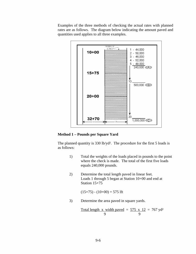
9-6
Examples of the three methods of checking the actual rates with planned rates are as follows. The diagram below indicating the amount paved and quantities used applies to all three examples.
Method 1 – Pounds per Square Yard
The planned quantity is 330 lb/yd². The procedure for the first 5 loads is as follows:
1) Total the weights of the loads placed in pounds to the point
where the check is made. The total of the first five loads equals 240,000 pounds.
2) Determine the total length paved in linear feet.
Loads 1 through 5 began at Station 10+00 and end at Station 15+75
(15+75) - (10+00) = 575 lft
3) Determine the area paved in square yards.
Total length x width paved = 575 x 12 = 767 yd²
9 9

9-7
4) Calculate the actual rate of spread in lb/yd²
Total mix placed (lb) = 240,000 lb = 313 lb/yd² Area paved (yd²) 767 yd²
5) Compare the placed quantity and planned quantity
If placed quantity = planned quantity: Mat is correct If placed quantity > planned quantity: Overrun If placed quantity < planned quantity: Underrun
The planned quantity equals 330 lb/yd². The placed quantity of 312.9 lb/yd² is less than the planned quantity indicating an underrun and a mat that is too thin. The Contractor is required to make the necessary adjustments. After load 10, the paver is at Station 20+00 and 500,000 pounds have been placed.
Total length = (20+00) – (10+00) = 1000 lft
Area = (1000 x 12) / 9 = 1333 yd² Placed Quantity = 500,000 / 1333 = 375 lb /yd² The placed quantity of 375 lb/yd² is greater than the planned quantity indicating an overrun.
After Load 20, the paver is at Station 32+70 and a total of 1,000,000 lb have been placed.
Total length = (32+70) – (10+00) = 2270 lft Area = (2270 x 12) / 9 = 3027 yd² Placed quantity = 1,000,000 / 3027 = 330.4 lb/yd² The placed quantity equals the planned quantity indicating the spread rate is correct.
Method 2 – Pounds per Linear Foot
The planned quantity is 330 lb/yd²
1) Convert the planned quantity from lb/yd² to lb/lft
length of one foot x width paved = 1 x 12 = 1.33 yd²/lft 9 ft²/yd² 9 planned quantity x yd²/lft = 330 x 1.33 = 440 lb/lft

9-8
2) Total the weights of the loads placed in pounds to the point where
the check is made.
The total of the first five loads equals 240,000 pounds
3) Determine the total length paved in linear feet
Loads 1 through 5 began at Station 10+00 and end at Station 15+75
(15+75) - (10+00) = 575 lft
4) Calculate the actual rate of spread in lb/lft
total mix placed = 240,000 lb = 417.4 lb/lft total length paved 575 lft
5) Compare the placed quantity and the planned quantity
The placed quantity of 417.4 lb/lft is less than the planned quantity of 440 lb/lft indicating that an underrun and a mat that is too thin.
After Load 10, the paver is at Station 20+00 and 500,000 pounds have been placed.
Total length = (20+00) – (10+00) = 1,000 lft Placed quantity = 500,000 / 1,000 = 500 lb/lft
The placed quantity of 500 lb/lft is greater than the planned
quantity of 440 lb/lft indicating an overrun and a mat that is too thick.
After Load 20, the paver is at Station 32+70 and 1,000,000 lb have been placed.
Total length = (32+70) – (10+00) = 2270 lft Placed quantity = 1,000,000 / 2270 = 440.5 lb/lft
The placed quantity equals the planned quantity indicating that the
spread rate is correct.

9-9
Method 3 – Tons per Linear Foot
The planned quantity is 330 lb/yd2
1) Convert the planned quantity from lb/yd² to t/lft
planned quantity (lb/yd²) x width of paving (ft) = 330 x 12 = 0.22 t/lft 9 (ft²/yd²) x 2000 (lb/t) 18,000
2) Total the weights of the loads placed in pounds to the point where
the check is made and convert to tons.
The total of the first five loads equals 240,000 pounds. Note: 2,000 pounds equals 1 ton.
pounds placed = 240,000 = 120 tons
2000 lb 2,000
3) Determine the total length paved in linear feet.
Loads 1 through 5 began at Station 10+00 and end at Station15+75
(15+75) – (10+00) = 575 lft
4) Calculate the theoretical quantity (tons) for the total length paved.
planned quantity (tons/lft) x total length paved (lft)
0.22 tons/lft x 575 lft = 126.5 tons
5) Compare the placed quantity and theoretical quantity
placed quantity – theoretical quantity = tons over/under
120 tons – 126.5 tons = -6.5 tons (Underrun)
Note: If net tons is positive, there is an overrun If net tons are negative, there is an underrun
6) Calculate % of underrun or overrun
net over/under (tons) x 100 = -6.5 x 100 = 5.14% underrun
theoretical quantity (tons) 126.5

9-10
Method 4 – linear feet covered per truck load A typical tri-axle truck contains a net weight of 20 tons of HMA. 1) Convert tons to pounds
(20 ton) x (2000 lb/ton) = 40000 lb 2) Divide the pounds of HMA by the adjusted lay rate to determine
the square yards a truckload will cover
22 yd 121
lb/yd 330lb 00040
=,
3) Convert the square yards to square feet
(121.2 yd2) x (9 ft2/yd2) = 1090.9 ft2
4) Divide by the width of paving to find the length covered in feet
ft 990ft 12
ft 91090 2..
=

10 Seal Coat Placement
Types of Seal Coats
Quality Control Plan
Equipment Distributor
Chip Spreader
Pneumatic-Tire Roller
Rotary Power Broom
Surface Preparation Aggregate Surface
Prime Coats
HMA Surfaces
Placement Weather Limitations
Traffic Control
Application of Asphalt Material
Application of Cover Aggregate
Application of Fog Seal
Application Rate Computations Asphalt Material
Cover Aggregate
Fog Seal
10-1
CHAPTER TEN:
SEAL COAT PLACEMENT
Seal coating consists of the application of liquid asphalt material to the
roadway followed immediately by the application of the aggregate.
Sometimes seal coats are referred to as chip seals. Seal coat applications
may include single or double coverage. Where double applications are
used, the first application of asphalt material is covered with aggregate,
rolled, and allowed to cure before the second coat is applied.
Seal Coats are covered in Section 404. Seal coats may be applied to
aggregate or HMA surfaces; however, the most common use by INDOT is
on HMA surfaces. When a seal coat is placed on an aggregate surface, a
prime coat (Section 405) is first applied and allowed to cure.
Seal coats are applied to HMA surfaces to:
1) Seal out moisture and air
2) Rejuvenate dry weathered surfaces
3) Improve skid resistance of the pavement
4) Improve visibility of delineation between the traveled way
and the shoulders
Seal coats applied directly to roadways with aggregate surfaces provide a
smooth, dust-free traveled way which eliminates the need for periodic re-
grading of the surface. This method of construction is normally used only
for low-volume roads.
INDOT typically uses seal coats on travel lanes on low volume roads or
on shoulders of roads of any traffic volume.
Fog seals are sometimes used in conjunction with seal coats. A fog seal is
a light application of liquid asphalt material to a pavement surface and is
commonly used on seal coated pavements to improve the cover aggregate
retention, assist the curing, and improve surface appearance. INDOT most
commonly uses fog seals on seal coated surfaces.
____________________________________________________________

10-2
TYPES OF SEAL COATS
Seven types of seal coats are used as indicated in the table below. The
types vary by the size of cover aggregate used and the number of
applications. Types 1 through 4 use single applications and types 5
through 7 are double applications.
Rates of Application
per Square Yard
Type Application
Cover
Aggregate
Size No.
Aggregate
(lb)
Asphalt
Material
(Gallons at 60°F)
1 or 1P Single 23, 24 12-15 0.12-0.16
2 or 2P Single 12 14-17 0.29-0.33
3 or 3P Single 11 16-20 0.36-0.40
4 or 4P Single 9 28-32 0.63-0.68
5 or 5P Double Top – 12
Bottom - 11
16-19
16-20
0.33-0.37
0.36-0.40
6 or 6P Double
Top -11
Bottom - 9
18-22
28-32
0.41-0.46
0.63-0.68
7 or 7P Double
Top - 11
Bottom - 8
18-22
28-32
0.41-0.46
0.63-0.68
Seal coat types which include a "P" in the designation utilize a polymer
based asphalt material, AE-90S. INDOT requires polymer modified
emulsion on all highway mainline applications. HFRS-2 is not to be used
with a Type I Seal Coat. Additional requirements related to allowable
asphalt materials for other seal coat types are included in Sections 404.03,
404.04, and 902.01(b). Seal coat asphalt materials require a Type A
certification for acceptance by INDOT.
For double applications, the coarser aggregate is used for the first
application. Section 904 includes the requirements for the aggregates used
in seal coats. The cover aggregates are required to be produced by a
CAPP approved source.

10-3
QUALITY CONTROL PLAN
A quality control plan which outlines the proposed seal coat operation is
required to be approved prior to beginning work. The QCP shall be in
accordance with ITM 803 (Appendix A).
EQUIPMENT
Four major pieces of Contractor equipment are required for seal coating: a
distributor, chip spreader, pneumatic-tired roller, and rotary power broom.
DISTRIBUTOR
The asphalt distributor (Figure 10-1) is the most important piece of
equipment on a seal coat operation. The uniform application of the
asphalt material at the appropriate rate is essential to achieve a quality seal
coat.
The distributor is required to be checked to ensure that the equipment is in
good working condition and complies with the Specification requirements.
The proper nozzles, nozzle angles, spray bar height, pump speed, and
pump pressure are items that are required to be checked. Clogged nozzles
are a common problem that prevents a uniform application of asphalt
material on the pavement surface. If the distributor does not apply a
uniform application of emulsion over the entire surface to be seal coated,
the operation is stopped immediately until the problem is corrected.
The distributor operation is optimized to ensure that the asphalt material is
applied to the pavement surface at the appropriate rate. Proper asphalt
material application rates vary depending on the existing pavement
condition. To achieve the required application rate, the distributor pumps
and speeds are required to be coordinated properly.
Figure 10-1. Asphalt Distributor
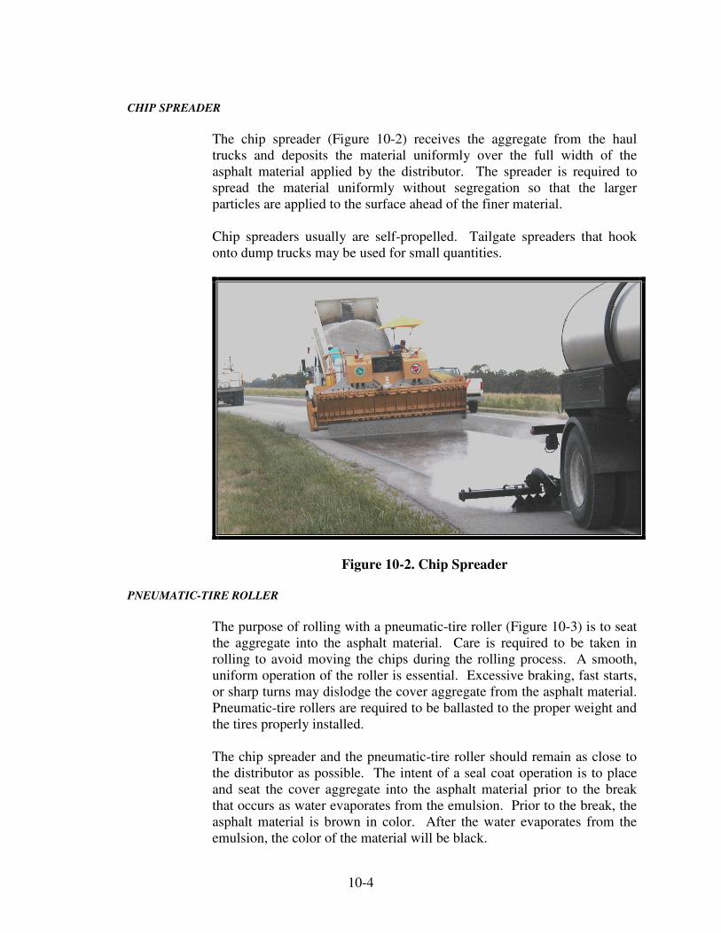
10-4
CHIP SPREADER
The chip spreader (Figure 10-2) receives the aggregate from the haul
trucks and deposits the material uniformly over the full width of the
asphalt material applied by the distributor. The spreader is required to
spread the material uniformly without segregation so that the larger
particles are applied to the surface ahead of the finer material.
Chip spreaders usually are self-propelled. Tailgate spreaders that hook
onto dump trucks may be used for small quantities.
Figure 10-2. Chip Spreader
PNEUMATIC-TIRE ROLLER
The purpose of rolling with a pneumatic-tire roller (Figure 10-3) is to seat
the aggregate into the asphalt material. Care is required to be taken in
rolling to avoid moving the chips during the rolling process. A smooth,
uniform operation of the roller is essential. Excessive braking, fast starts,
or sharp turns may dislodge the cover aggregate from the asphalt material.
Pneumatic-tire rollers are required to be ballasted to the proper weight and
the tires properly installed.
The chip spreader and the pneumatic-tire roller should remain as close to
the distributor as possible. The intent of a seal coat operation is to place
and seat the cover aggregate into the asphalt material prior to the break
that occurs as water evaporates from the emulsion. Prior to the break, the
asphalt material is brown in color. After the water evaporates from the
emulsion, the color of the material will be black.

10-5
Figure 10-3. Pneumatic-Tire Roller
ROTARY POWER BROOM
A power rotary broom (Figure 10-4) is required for cleaning the surface
prior to seal coating and to remove excess cover aggregate within 24 hours
after the seal coat application. Power brooms may be self-propelled,
mounted on the front of tractors, or mounted on trailers pulled behind
other vehicles. Some manufacturers make special machines for this
purpose.
Figure 10-4. Rotary Power Broom

10-6
SURFACE PREPARATION
Surface preparation is extremely important for successful seal coating.
The surface is required to be clean, dust free, and dry to obtain proper
adhesion of the seal coat. Preparation of the surface varies somewhat,
depending on the type of surface.
AGGREGATE SURFACE
Aggregate surfaces are required to be brought to the proper crown and
grade and thoroughly compacted. Aggregate surfaces that have been
under traffic typically have potholes and chatter bumps (washboarding)
which are required to be removed. Removal may be done by scarifying a
minimum of 3 in. deep, reshaping, and re-compacting. The surface is
required to be free from all ruts, corrugations, segregated material, or other
irregularities.
PRIME COATS
A prime coat is the application of asphalt material to an aggregate,
stabilized base, or similar absorptive base that is to be given an asphalt
surface. The purpose of the prime coat is to act as a bonding agent
between the base and the seal coat. Prime coat materials penetrate into the
base a slight amount to help hold down the dust which would prevent the
seal coat from sticking. Prime coats are only used when a chip seal is
applied to an aggregate surface.
Prime coats may be applied only when the temperature is 50º F or higher,
unless written permission is given by the PE/PS. The existing surface is
required to conform to the requirements for an aggregate pavement, as
described in Section 303, before the prime coat is applied.
The asphalt material for a prime coat is required to be applied uniformly
with a distributor at the specified temperature. The rate of application
may vary from 0.25 to 0.80 gallons per square yard depending on the
condition of the surface and the kind, gradation, and amount of loose
aggregate. Skipped areas are required to be corrected and any excess
material removed from the surface. Building paper is required to be
placed over the ends of previous applications and the joining application
started on the paper to prevent excess material build-up. The prime coat is
cured when the material ceases to be tacky, usually within 24 hours. If the
prime coat does not penetrate after a reasonable time and the primed area
is required to be opened to traffic, cover aggregate is spread to absorb the
excess material. When traffic is required to be maintained not more than
one-half of the width of the roadway may be primed at one time.

10-7
HMA SURFACES
All defective areas and broken edges of existing HMA surfaces are
required to be repaired prior to sealing. The old surface is brought to a
reasonable degree of uniformity by correcting flushed or dry areas and
patching potholes and dips.
Cleaning the existing surfaces may normally be done with a power rotary
broom. However, mud or other foreign matter may require removal with
shovels, hand brooms, or water.
PLACEMENT
WEATHER LIMITATIONS
The best weather for seal coating is hot and dry, during and after the
application. Sealing is never started when the surface is wet or rain is
threatening. The Specifications require that both the air and surface
temperatures be at least 60ºF. In addition to the temperature restrictions,
seal coats may only be applied to the mainline pavement between May 1
and October 1. Shoulders are not subject to these date limitations.
Special care is required to protect the traveling public from over-spray
from the distributor in windy weather. Sealing is not allowed in strong
winds because crosswinds disturb the flow of asphalt materials from the
nozzles which may cause spray interference and streaking.
TRAFFIC CONTROL
Because seal coats are often applied to road surfaces under traffic, special
traffic control measures are needed. The seal coat is required to be
protected from the traffic until the material has cured enough to prevent
pick-up or displacement of the cover aggregate and until the chips are
firmly embedded.
Traffic control is usually done during the initial curing period by the use
of flagmen and pilot cars. Later, the traffic control may be handled with
signing. Traffic is piloted through the work at speeds low enough to
prevent damage to the newly placed seal coat. Normally, the speed should
be less than 25 miles per hour. Care is required to be taken to prevent
sudden starts or stops on the new seal. When stopping traffic on a new
seal coat, additional cover aggregate at the stop locations may be
necessary to prevent pick-up of the cover aggregate and tracking of the
asphalt material.
The length of time that traffic is controlled depends on the weather and the
type of asphalt applied. During cool, damp, cloudy, or humid weather,
longer control periods are necessary than when the weather is warm, dry,

10-8
and sunny. Cool, damp weather delays the evaporation of the moisture in
the cover aggregate and the setting rates of the asphalt material. During
very hot weather, traffic is controlled longer if there is a possibility of
chips rolling or picking up under traffic. Traffic is controlled during that
portion of the day when damage may occur to vehicles due to flying rocks
or to the seal coat. Traffic control may be necessary during the second
day after seal coat placement.
Following an unexpected rainstorm, traffic is kept off of the new seal coat
until the cover aggregate has dried. If this is not possible, controlling
traffic at an extremely slow rate is necessary and rolling is not continued
until the danger of dislodging the aggregate has passed.
Traffic control is provided and the work scheduled to handle the traffic
with a minimum delay. Most extended delays, exposure of the traffic to
unnecessary hazards or inconveniences, or damage to the seal coat are the
result of poor planning for traffic control. Traffic is never allowed to pass
a distributor which is applying asphalt material if there is any possibility
of asphalt being sprayed on the vehicles.
APPLICATION OF ASPHALT MATERIAL
Asphalt material is applied to the roadway with a pressure distributor to
obtain a uniform application. The distributor is required to heat the
material to the designated temperature range. A continuous, uniform
application of the asphalt material over the width to be sealed is required
for a good seal coat. The distributor is tested for uniform application prior
to beginning the sealing operation. The distributor is required to not be
more than one minute ahead of the chip spreader.
The biggest problem in applying asphalt materials is the prevention of
streaking. Streaking results in alternating areas with an excessive amount
of asphalt immediately adjacent to one with insufficient asphalt and is
usually caused by one of the following conditions:
1) Asphalt at the improper temperature
2) Interference of the sprayed material from one nozzle with
that of adjacent nozzles
3) Improper pump speed
4) Improper spray bar height
5) Clogged nozzles

10-9
The required corrective actions for the above conditions are as follows:
1) Maintain the temperature of the asphalt material at the high
end of the range suggested by the emulsion supplier.
2) Orient all nozzle openings in accordance with the
manufacturer’s recommendations. All nozzles are set at the
same angle to prevent interference (Figure 10-5). Special
wrenches are available to ensure that the nozzles are
aligned uniformly. Generally, the smaller the nozzle
opening, the more uniform the application of asphalt
material. Worn or damaged nozzles are required to be
replaced.
Figure 10-5. Distributor Nozzles
3) The highest possible pump speed that does not cause
distortion of the spray fan is the correct speed to use. Low
speed applications result in streaking and non-uniform
discharge. Manufacturers provide charts and data for
proper pump speed or pressure and for determining the
discharge in gallons per minute for each nozzle size.
4) Clogged nozzles are usually the result of allowing the spray
bar to cool between applications. This causes the material
at the bar to harden. Circulating the hot material through
the spray bar until the bar reaches the temperature of the
material generally melts the obstruction. A quick test shot
before starting is recommended.
5) Improper spray bar height is the principal cause of
streaking. Visual observation while the distributor is
moving does not reveal whether an exact double or triple
lap is being applied. Without prior checking, only time
reveals the lack of uniformity of the seal coat application.
10-10
The optimum spray bar height is also dependent on the bar’s nozzle
spacing. The spray bar height/nozzle spacing combination should produce
either an exact double or triple overlap of the adjacent fans. Generally,
closer nozzle spacings are required to achieve triple overlaps. When the
proper spray bar height/nozzle spacing combination is achieved, the
distributor will be able to maintain the spray bar height regardless of the
amount of asphalt material in the tank.
Transverse Joints
Irregular transverse joints may be avoided by starting and stopping the
application of the asphalt on building paper. The paper is placed across
the lane to be treated so the forward edge is at the desired location. The
distributor, traveling at the correct speed for the desired application rate,
starts spraying on the paper so there is a full uniform application when the
exposed surface is reached. A second placement of paper is made across
the lane at the predetermined cutoff point for the distributor. This
procedure gives a straight, sharp transverse joint. After the aggregate
spreader has passed over the building paper, the paper is removed and
discarded.
For the next application, the leading edge of the paper is placed within 1/2
in. of the cutoff line of the previously laid treatment. This procedure
prevents a gap between the two spreads.
Longitudinal Joints
Full-width applications of asphalt and aggregates eliminate longitudinal
joints. In most seal coat work, the joint is unavoidable because the
roadway is too wide for one pass or traffic lanes are required to be
maintained.
To prevent aggregate from building up on the longitudinal joints, the edge
of the aggregate spread is required to coincide with the edge of the full
thickness of applied asphalt. This procedure allows a width where asphalt
is present in partial thickness to be overlapped when asphalt is applied to
the adjacent lane. The partial thickness is the result of the outside nozzle
spray being only partially overlapped. In this way there is no build up at
the joint when the aggregate is spread for the full width in the next lane.
The width of the asphalt strip left exposed varies depending on the nozzle
spacing and whether the asphalt is a double or triple lap spray pattern.
If possible, the longitudinal joint is required to be along the centerline of
the pavement being treated. An established line ensures a straight
longitudinal joint.

10-11
The distributor is parked off the roadway when not in use so the spray bar
or mechanism does not drip asphalt materials onto the traveled way, either
before or after seal coating.
APPLICATION OF COVER AGGREGATE
Cover aggregate is required to be clean and sufficiently dry so that a
satisfactory bond with the asphalt material is obtained. If the aggregate is
dusty, the material is moistened with water to eliminate or reduce the dust
coating on the aggregate at least 24 hours prior to use. The moisture
content should not exceed 3 %.
When the distributor moves forward, the aggregate spreader is required to
follow immediately. To minimize the number of transverse joints, a
sufficient number of trucks should be available to transport the cover
aggregate to the job site. The cover aggregate is required to be applied
within 1 min of the application of the asphalt material. The aggregate is
required to be spread such that the tires of the trucks or aggregate spreader
do not contact the uncovered and newly applied asphalt material. In a
single application, aggregate normally does not stick to the asphalt more
than one particle thick; therefore, applying aggregate at a rate greater than
a single layer is wasteful.
Rolling seats the aggregate in the asphalt and promotes the bond necessary
to resist traffic stresses. One pass forward, one pass back, and another
pass forward again are required over each area. Pneumatic-tired rollers
are required for seal coating. Steel-wheel rollers generally only compact
the high spots and may crush the aggregate. Pneumatic-tired rollers apply
uniform pressure over the entire area.
Immediately after the cover aggregate is spread but before rolling, any
area with a deficiency or surplus of aggregate is required to be corrected.
Rolling begins immediately behind the aggregate spreader and continues
until at least three complete roller passes have been made. The first roller
application is required to be completed within 2 min of the aggregate
application. Final rolling is required to be completed within 30 min after
the cover aggregate is applied.
The finished seal coat is required to exhibit a tightly knit surface one
particle thick (single seal), have enough asphalt binder to seat the
aggregate 50 to 65 percent of the aggregate particle, and orient the
particles on the average least dimension (Figure 10-6). A common
tendency is to apply both the aggregate and the asphalt at an excessive
rate.

10-12
Figure 10-6. Aggregate Average Least Dimension
Fuel or hydraulic fluid leaks from the equipment ruin the appearance of
the seal coat, cause permanent damage, and are to be avoided. Areas
where leaks occur are required to be repaired as soon as possible to
minimize permanent damage to the pavement.
Despite precautions, there is usually loose aggregate on the road surface
after rolling is completed. The excess coarse aggregate is required to be
removed from the mainline pavement surface by brooming no later than
the morning after the placement of the seal coat. Care must be exercised
during this brooming operation as the asphalt material may not be fully
cured at this time. If the broom is allowed to put excessive force on the
seal coated pavement, embedded cover aggregate may be swept from the
asphalt material and the pavement may require an additional seal coat. A
second brooming operation is required prior to opening to unrestricted
traffic in accordance with Section 101.33.
APPLICATION OF FOG SEAL
A fog seal (Section 412) is placed on top of the cover aggregate. The
purpose of a fog seal is to lock the cover aggregate into the seal coat, aid
the curing, and improve the surface appearance. The weather and calendar
requirements associated with a seal coat also apply to the application of a
fog seal.
The fog seal is required to be applied uniformly at the appropriate rate. If
too little asphalt material is applied or is not applied in a uniform manner,
the seal coat cover aggregate will not be locked in as intended. If too
much asphalt material is applied, there will likely be friction problems
with the pavement surface.

10-13
APPLICATION RATE COMPUTATIONS
ASPHALT MATERIAL
The Specification application rates for asphalt materials are based on
material at 60º F. Since the material is applied at a higher temperature and
expands in volume when heated, an allowance is required to be made for
the increase in volume.
The formula for calculation of the volume at 60º F from a volume at an
observed temperature is:
160)(TK
VV
1
+−
=
where: V = volume at 60º F.
V1 = volume at the observed temperature
T = observed temperature in degrees F
K = coefficient of expansion of asphalt material
The coefficient of expansion to be used in making the volume corrections
for asphalt emulsion is 0.00025/° F.
Distributors are required to have a gauge for determining the gallons of
material in the tank before and after each application. The difference is
the amount applied. Weighing the distributor before and after the
application is another acceptable method. The weight of asphalt material
in the tank may be converted to a volume in gallons with the following
formula:
8.328S.G x
WG =
where:
G = volume in gallons at 60º F
W = weight of asphalt material in pounds
S.G. = specific gravity of asphalt material at 60º F
8.328 = the weight of one gallon of water at 60º F
The laboratory report with the certification indicates the specific gravity
and the weight per gallon at 60º F for all asphalt materials.

10-14
Example #1 – Determine application rate
Plan rate of application of asphalt material is 0.32 gal/yd2 at 60º F
Temperature of the asphalt in the distributor is 270º F
K = 0.00025
V1 = V (K (T-60) +1)
V1 = 0.32 (0.00025 (270-60) +1)
V1 = 0.34 gal/yd2 at 270º F
Example #2 – Determine distributor speed
The speed of the distributor and length of spread are determined before
spraying starts. The distributor speed may be determined by the following
formula.
WA
Q 9V =
where: V = road speed in feet per minute
Q = spray bar output in gallons per minute
W = spray bar width in feet
A = application rate in gallons per square yard at the application
temperature (as computed in Example #1)
Asphalt material as in Example #1
Spray bar width = 12 feet
Pump capacity = 325 gallons per minute
minuteper feet 7130.34 x 12
325 x 9V ==
Example #3 – Determine actual application rate
Width of application = 12 feet
Beginning station = 10+00
Ending station = 15+75
Gallons in tank at start = 1230
Gallons in tank at end = 960
Temperature in the distributor = 270º F

10-15
2
22yd 767
/ydft 9
1000) (1575 12covered Area =
−=
F 60at gal/yd 0.35767
9601230raten Applicatio 2 o
=−
=
F 60at gal/yd 0.33160)(270 0.00025
0.35
160)(TK
VV 21 o
=
+−
=
+−
=
The actual rate of application is 0.33 gal/yd2 which is slightly
higher than the planned rate of 0.32 gal/yd2; however, this amount
is within reasonable tolerances.
Example #4 – Convert weight to gallons
Weight of asphalt material = 14,000 lb
Specific gravity at 60º F = 0.980
F 60at gallons 17158.328 x 0.980
14,000V o
==
COVER AGGREGATE
Application rates for cover aggregate are determined in a similar manner
as the application rates of asphalt material.
Example #5 – Determine the cover aggregate application rate
Weight of cover aggregate applied = 15,200 lb. (from weigh
tickets)
Use the area covered from Example #3
2lb/yd 20767
15,200
covered area
usedquantity raten Applicatio ===
The actual rate is compared with the planned rate. Adjustments in the gate
opening are required to reduce or increase the actual rate to conform to the
planned rate.
Test runs are required to be made to check the application rates of both the
asphalt and cover aggregate prior to commencing sealing operations.

10-16
FOG SEAL
The fog seal application rate adjusted for temperature is calculated in the
same manner as seal coat asphalt material in Example #1. The required
fog seal distributor speed calculation is made in the same manner as
Example #2. The actual fog seal application rate is calculated in the same
manner as Example #3.

Appendices A-E
Appendix A – Indiana Test Methods
1. ITM No. 580 4. ITM No. 803 2. ITM No. 588 5. ITM No. 812 3. ITM No. 802 6. ITM No. 912
Appendix B
(intentionally left blank)
Appendix C
1. Pre-Start Up Project Safety Checklist A 2. Start-Up Work Zone Evaluation Checklist B 3. Daily Productions Checklist C 4. Shut Down Safety Checklist D 5. Complete Project Maintenance Checklist E
Appendix D
1. Mix Delivery Production Caluculation Form 2. Paving Production Calculation Form 3. Compaction Production Calculation Form


