35
CGT 110 – Technical Graphics Communication Week 5: Auxiliary Views
| Date post: | 13-Dec-2015 |
| Category: |
Documents |
| Upload: | maryann-sims |
| View: | 228 times |
| Download: | 1 times |

CGT 110 – Technical Graphics Communication
Week 5:
Auxiliary Views

CGT 110 – Technical Graphics Communication
Week 5: Auxiliary Views
Here’s what we talked about last time…..

CGT 110 – Technical Graphics Communication
Week 5: Auxiliary Views
We place hidden lines in a drawing to do the following things:
1. Show hidden features
2. Clarify the position and shape of features
3. Make the “plate” more readable
(NOTE: The term “plate” refers to a finished drawing.)

CGT 110 – Technical Graphics Communication
Week 5: Auxiliary Views
Depending on the application, hidden lines will either touch other hidden lines, or pass over them
Note how hidden lines follow specific rules as to how they are to be laid out.

CGT 110 – Technical Graphics Communication
Week 5: Auxiliary Views
Center lines are used to show the theoretically perfect center of holes, arcs, cylinders and bolt circles*
*A “bolt circle” is used to position holes or cylinders in a circular pattern.

CGT 110 – Technical Graphics Communication
Week 5: Auxiliary Views
Rounds and Fillets are used to relieve stress and finish edges on manufactured goods.

CGT 110 – Technical Graphics Communication
Week 5: Auxiliary Views
Partial views are often used to simply symmetrical objects.

CGT 110 – Technical Graphics Communication
Week 5: Auxiliary Views
“Revolved” views are used to give a clearer representation of an object. We actually “draw the object incorrectly to make it easier to understand”. Here, webs have revolved to 12, 3 and 6 o’clock positions to make the view easier to visualize.
CGT 110 – Technical Graphics Communication
Week 5: Auxiliary Views
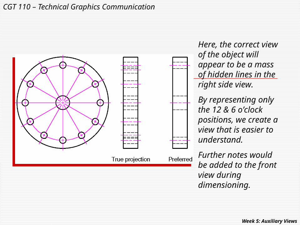
Here, the correct view of the object will appear to be a mass of hidden lines in the right side view.
By representing only the 12 & 6 o’clock positions, we create a view that is easier to understand.
Further notes would be added to the front view during dimensioning.
CGT 110 – Technical Graphics Communication
Week 5: Auxiliary Views
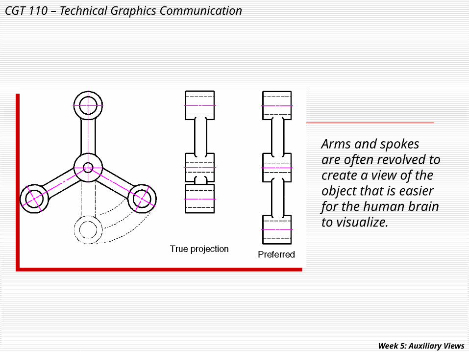
Arms and spokes are often revolved to create a view of the object that is easier for the human brain to visualize.
CGT 110 – Technical Graphics Communication
Week 5: Auxiliary Views
Let’s now take a look at how we can show an oblique surface’s “True Shape and Size” using auxiliary views…..

CGT 110 – Technical Graphics Communication
Week 5: Auxiliary Views
We have already seen how the principle views of an object can be represented when using the glass box approach to surface identification.
However, this object has a surface that is not parallel to any side of the glass box.
How can we represent that surface in its true shape and size?

CGT 110 – Technical Graphics Communication
Week 5: Auxiliary Views
Here, surface ABCD is shown in all 3 views.
In which view is it true shape and size?
Answer:
In none of them!

CGT 110 – Technical Graphics Communication
Week 5: Auxiliary Views
We can also use the glass box technique by adding another plane and project this surface unto it.
By doing so, we can show the slanted surface’s true shape and size.
NOTE:
The new glass plane is parallel to the surface it describes just like the other glass projection planes.

CGT 110 – Technical Graphics Communication
Week 5: Auxiliary Views
Just the way we unfold the glass box to expose all of the principle views…..

CGT 110 – Technical Graphics Communication
Week 5: Auxiliary Views
…we can unfold the projection plane that is parallel to the slanted surface we wish to show as true shape and size.
CGT 110 – Technical Graphics Communication
Week 5: Auxiliary Views
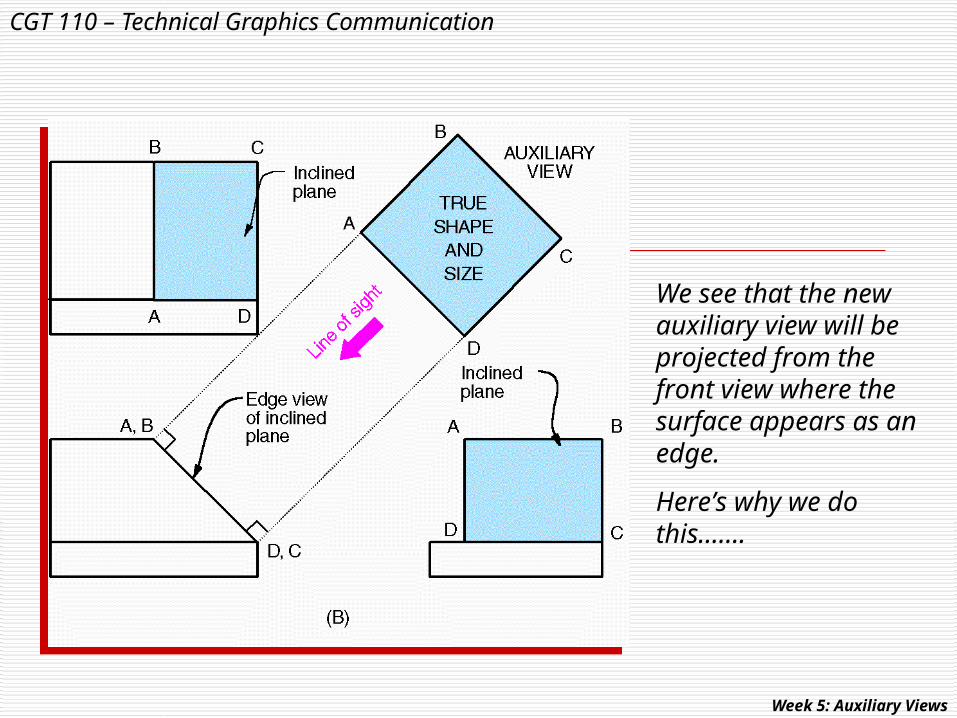
We see that the new auxiliary view will be projected from the front view where the surface appears as an edge.
Here’s why we do this…….

CGT 110 – Technical Graphics Communication
Week 5: Auxiliary Views
Between each view are imaginary lines that represent the edge view of the planes of projection.
These planes allows us to use the character-istics of the lines that make up each view.
For example…..
CGT 110 – Technical Graphics Communication
Week 5: Auxiliary Views
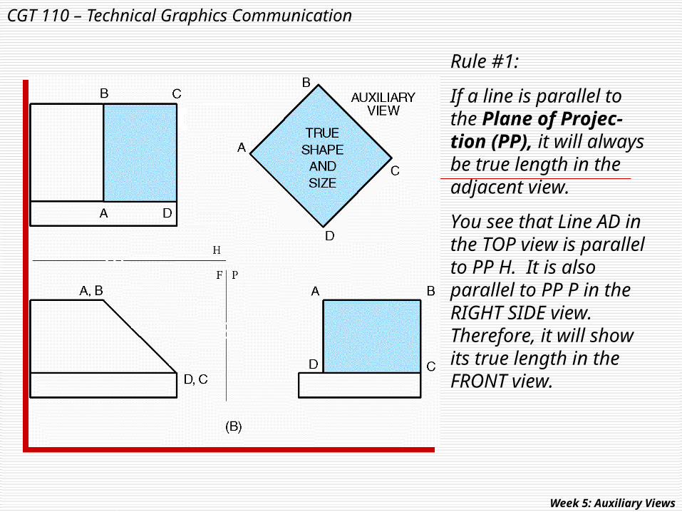
Rule #1:
If a line is parallel to the Plane of Projec-tion (PP), it will always be true length in the adjacent view.
You see that Line AD in the TOP view is parallel to PP H. It is also parallel to PP P in the RIGHT SIDE view. Therefore, it will show its true length in the FRONT view.

CGT 110 – Technical Graphics Communication
Week 5: Auxiliary Views
Rule #2:
If a line appears as a point in any view, it will be true length in the adjacent view.
You can see that line DC appears as a point in the FRONT view. Therefore, it is true length in both the TOP and RIGHT SIDE views.
CGT 110 – Technical Graphics Communication
Week 5: Auxiliary Views
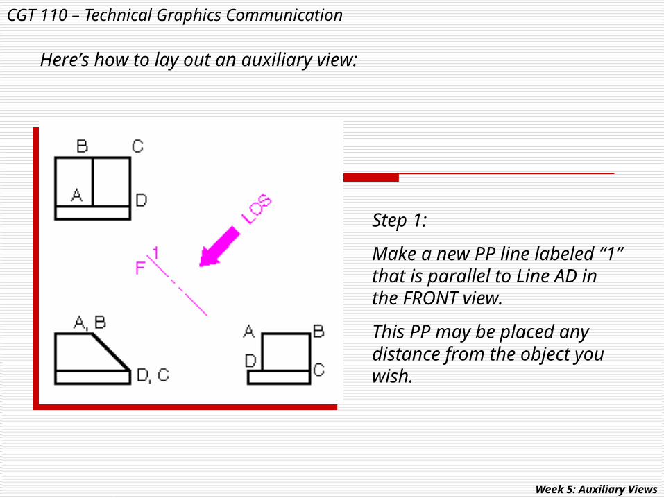
Here’s how to lay out an auxiliary view:
Step 1:
Make a new PP line labeled “1” that is parallel to Line AD in the FRONT view.
This PP may be placed any distance from the object you wish.

CGT 110 – Technical Graphics Communication
Week 5: Auxiliary Views
Step 2:
Add the other PP lines as shown so they will connect to PP 1.
It is always a good idea to label the PPs as shown.
CGT 110 – Technical Graphics Communication
Week 5: Auxiliary Views
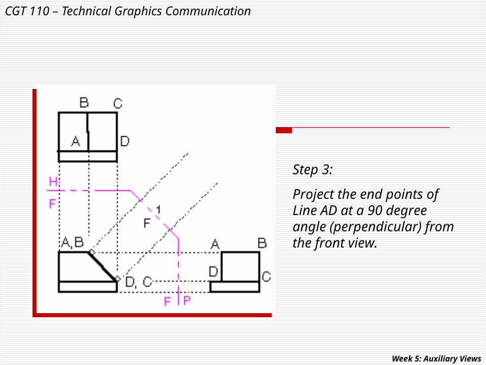
Step 3:
Project the end points of Line AD at a 90 degree angle (perpendicular) from the front view.

CGT 110 – Technical Graphics Communication
Week 5: Auxiliary Views
Step 4:
Transfer the distance from PP to point C in the TOP view…
…to its new position from PP 1 in the auxiliary view.

CGT 110 – Technical Graphics Communication
Week 5: Auxiliary Views
Step 5:
Connect the new point C with the projected line to find point B.
Do the same thing for points A and D.

CGT 110 – Technical Graphics Communication
Week 5: Auxiliary Views
Step 6:
Snap your lines in the auxiliary view to create its final form.
NOTE: You do not need to label all points on your drawing.

CGT 110 – Technical Graphics Communication
Week 5: Auxiliary Views
Auxiliary views may either show the “Full” image of the part….
….or be a "Partial” view of only the surface we wish to view.

CGT 110 – Technical Graphics Communication
Week 5: Auxiliary Views
This technique uses points in the principle views that have been transferred to the auxiliary view to create true shape features.
“Reverse Construction” technique….

CGT 110 – Technical Graphics Communication
Week 5: Auxiliary Views
…Another reverse construction application…

CGT 110 – Technical Graphics Communication
Sketching Assignments
Given two orthographic views of an object, your task is to create the auxiliary view.

CGT 110 – Technical Graphics Communication
Week 2: Sketching, Text, and Visualization
#1

CGT 110 – Technical Graphics Communication
Week 2: Sketching, Text, and Visualization
#4

CGT 110 – Technical Graphics Communication
Week 2: Sketching, Text, and Visualization
#6

CGT 110 – Technical Graphics Communication
Week 2: Sketching, Text, and Visualization
#7

CGT 110 – Technical Graphics Communication
Week 6:
Section Views


