257 CHAPTER 16 UNIVERSITY OF MASSACHUSETTS AT LOWELL Department of Electrical and Computer Engineering University of Massachusetts Lowell, Lowell, MA 01854 Principal Investigator: Dr. Donn Clark (978) 934-3341 [email protected]
Transcript
257
CHAPTER 16 UNIVERSITY OF MASSACHUSETTS AT
LOWELL
Department of Electrical and Computer Engineering University of Massachusetts Lowell,
258 NSF 2007 Engineering Senior Design Projects to Aid Persons with Disabilities
DISCRETE TRIAL TEACHING GAME Designer: Brian T. Lavoie
Client: Ferryway School in Malden, MA Supervising Professors: Charles Maffeo and Alan Rux Department of Electrical and Computer Engineering
University of Massachusetts at Lowell Lowell, MA 01854-5104
INTRODUCTION The Discrete Trial Teaching Game (DTTG) (Fig. 16.1) was designed to help students with autism learn by using light and sound. DTTG presents the students with three stimulus flashcards. The teacher selects the correct flashcards. The game then compares the teacher’s choice to the student’s choice and displays green or red LEDs around the correct or incorrect choice. DTTG plays melodies for correct and incorrect choices and dispenses candy as positive reinforcement for correct choices.
SUMMARY OF IMPACT The device helps students maintain focus and interest during lessons. The device is fun for the students, provides positive reinforcement, and reduces steps required by the teacher during lessons.
TECHNICAL DESCRIPTION The device entails five interactive stages: 1) input; 2) logic circuitry; 3) the ISD 2560 chip-recorder; 4) the LED display; and 5) the candy dispenser.
The inputs for the teacher are four push-button switches. One switch is for resetting the game between each trial, and three switches are for selecting one of the three stimuli as the correct choice. The student has three inputs. These inputs utilize the Parallax QT113 touch sensors, which are connected to copper pads under the flashcards. The student places his or her finger over his or her choice and this activates the touch sensor.
The logic circuitry of the game is programmed onto a complex programmable logic device (CPLD), which comes with a programming board and software made by Xilinx. The input is seven
switches. Outputs consist of single correct and incorrect choice indicators, 24 bicolor LEDs, enabling and addressing the ISD2560 chip-recorder, and an activation of the candy dispenser for correct choices.
The LEDs are bicolor red or green with a common cathode. Eight LEDs are around each cardholder.
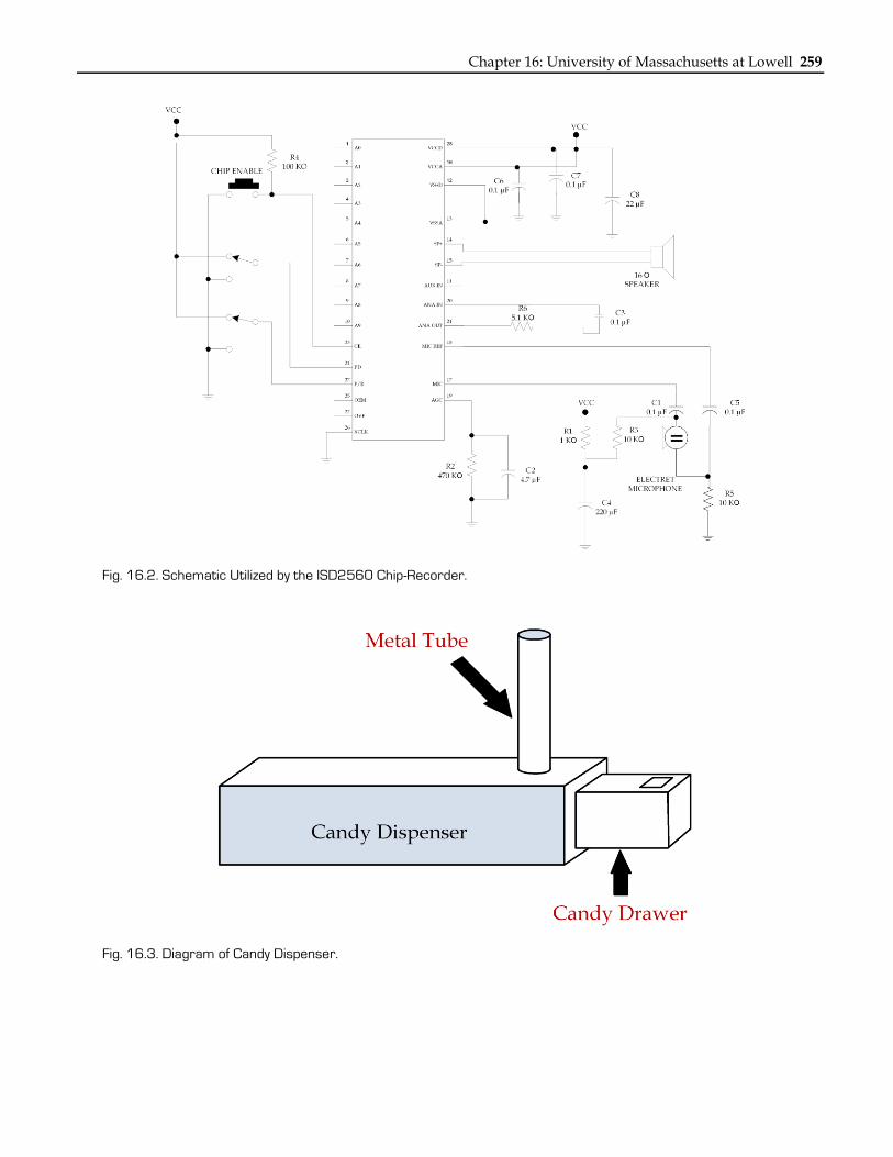
The ISD2560 chip-recorder (Fig. 16.2) utilizes addressing to play back a maximum of 60 seconds of sound over 600 address spaces, which provides 0.1 seconds of recording per address space. The chip stores six unique sounds in different addresses.
After a correct choice, candy is loaded into a drawer from a tube mounted on the device. After the student takes the candy, the game is reset, and the candy drawer is pushed back in position to load another piece of candy (Fig. 16.3).
The total cost of the device was about $287.
Fig. 16.1. Discrete Trial Teaching Game.
Chapter 16: University of Massachusetts at Lowell 259
Fig. 16.2. Schematic Utilized by the ISD2560 Chip-Recorder.
Fig. 16.3. Diagram of Candy Dispenser.
260 NSF 2007 Engineering Senior Design Projects to Aid Persons with Disabilities
MATCHING CARD GAME Designer: Christine Brunelle
Client Coordinator: Karen Mercurio, Brookside Elementary School, Dracut MA Supervising Professor: Alan Rux
Electrical and Computer Engineering Department University of Massachusetts at Lowell
Lowell, MA 01854
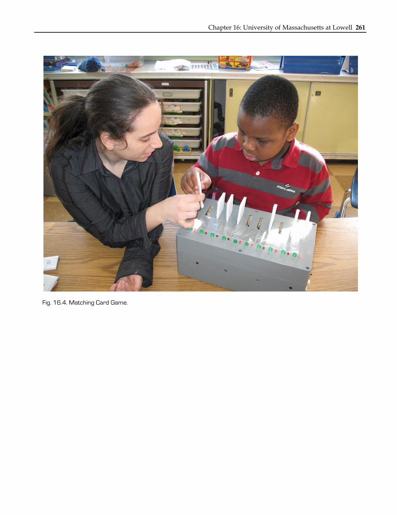
INTRODUCTION The Matching Card Game (Fig. 16.4) is a learning tool for kindergarten students with cognitive and physical disabilities. The device has ten slots with pictures behind them. The slots accept cards with the same pictures. When a card is inserted into a slot, the box determines whether the right card was inserted based on holes or notches that are in the card and outputs a signal based on the answer. If the correct card is put into the correct slot, a green light turns on and a musical tune plays; if a wrong card is put into the wrong slot, a red light turns on and a buzzing sound plays. The pictures on the cards can be modified by the teacher, who requested a system that does not require constant supervision. The Matching Card Game is an independent learning tool that allows students to be left alone while learning.
SUMMARY OF IMPACT The device increases the number of children that the teacher can attend to at one time and allows students to learn without constant supervision. The game gives the students independence and a sense of accomplishment. The game’s ability to be modified for higher level classes increases the ways in which it may be used.
TECHNICAL DESCRIPTION The game has four main parts: 1) optical switches; 2) multiplexers; 3) a microcontroller; and 4) light emitting diodes (LEDs). Four optical switches are placed in each slot to allow for a binary number up to ten. Each card has notches or holes in a particular order, corresponding to the correct slot for that card. When a card is inserted, the outputs from the optical switches go to the multiplexers and are fed into the microcontroller. The microcontroller determines whether the input is correct for the slot being read from. It then outputs accordingly and then switches over to the next slot. The microcontroller operates the multiplexers to read slots one through ten sequentially and constantly check the status of the slot.
The components were put into a box made of ABS plastic. The optical switches (H21A1, 40 total) were chosen because they were slotted. The multiplexers (74150, 4 total) are 16-1 bit converters so that the microcontroller (Basic Stamp BS2p40, 1 total) can scroll between slots and have a parallel input. At the request of the teacher, large green LEDs were used instead of red LEDs.
The cost of the parts and materials was about $300.
Chapter 16: University of Massachusetts at Lowell 261
Fig. 16.4. Matching Card Game.
262 NSF 2007 Engineering Senior Design Projects to Aid Persons with Disabilities
AUTOMATED LASER POINTING DEVICE Designer: John C. Newton
Client Coordinator: Jill, Helping Hands Monkey Helpers, Boston, MA Supervising Professor: Alan Rux
Department of Electrical and Computer Engineering University of Massachusetts at Lowell
Lowell, MA 01854
INTRODUCTION The Automated Laser Pointing Device was designed to help individuals who train or have Capuchin monkeys to point out objects in a room. The monkeys are trained to help individuals with disabilities by retrieving the selected object(s) or by performing a task on the selected object(s). The device consists of a hand-held joystick that communicates the desired coordinates wirelessly to a receiver. The receiver controls the position of the laser via two servos.
SUMMARY OF IMPACT The device helps individuals who are unable to physically manipulate a typical laser pointer. It provides the clients more control over their environment and decreases their dependence on caretakers.
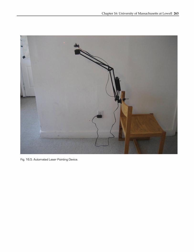
TECHNICAL DESCRIPTION The automated laser pointer has two separate modules (Fig. 16.5): 1) a transmitter and 2) a receiver. The transmitter module is a wireless handheld unit. It has: 1) a power switch; 2) a button; and 3) a small analog 2-axis joystick. A microcontroller runs a small program that controls the operation of the device. An RF transmitter sends data wirelessly to an RF receiver in the receiver module. The receiver module contains a microcontroller running its own program. The laser is mounted on two servos, which are directly connected to the receiver via a cable. It has a power switch and a power indicator LED.
The client operates the joystick to select an object in the room. The joystick has an X axis (left and right) and a Y axis (up and down). For fine adjustments, small deviation from the central axis results in slow movement of the laser. For coarse adjustments, large deviation from the central axis results in fast movement of the laser. Once the laser is positioned correctly, the client activates the button to excite the laser. Exciting the laser shakes it in close proximity to the object to get the monkey's attention. The transmitter module wirelessly transmits the desired state of the laser to the receiver module at 9600 baud. The receiver module interprets the state and positions the laser accordingly by sending pulse-width-modulated (PWM) signals to the servos.
The device is intended to operate indoors, in close proximity to the client and the monkey. The laser must remain in the field of view of both the client and the monkey. The receiver module can be mounted to: 1) a wheelchair; 2) a table; or 3) a bed frame. The servo/laser mechanism is affixed to an adjustable arm to ease the initial set up. The transmitter module is a handheld device that remains with the client.
The receiver module is powered by an AC/DC adapter, which provides five volts and ten Watts. The transmitter module consumes less than eight mA during normal operation and is powered by four AA batteries providing 4.8 volts and 2500mAh.
The cost of the parts and materials for each unit is less than $300.
Chapter 16: University of Massachusetts at Lowell 263
Fig. 16.5. Automated Laser Pointing Device.
264 NSF 2007 Engineering Senior Design Projects to Aid Persons with Disabilities
SMART INTERACTIVE TEACHER (SIT) Designer: Manuel Madera
Client Coordinator: Pamela Fraser (Teacher), Lawrence High School, Lawrence, MA Supervising Professor: Prof. Alan Rux
Electrical and Computer Engineering Department University of Massachusetts at Lowell
Lowell, MA 01854
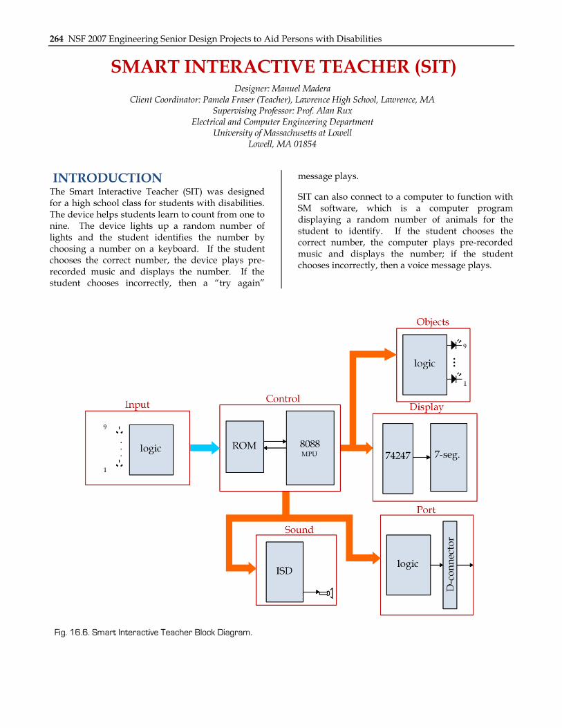
INTRODUCTION The Smart Interactive Teacher (SIT) was designed for a high school class for students with disabilities. The device helps students learn to count from one to nine. The device lights up a random number of lights and the student identifies the number by choosing a number on a keyboard. If the student chooses the correct number, the device plays pre-recorded music and displays the number. If the student chooses incorrectly, then a “try again”
message plays.
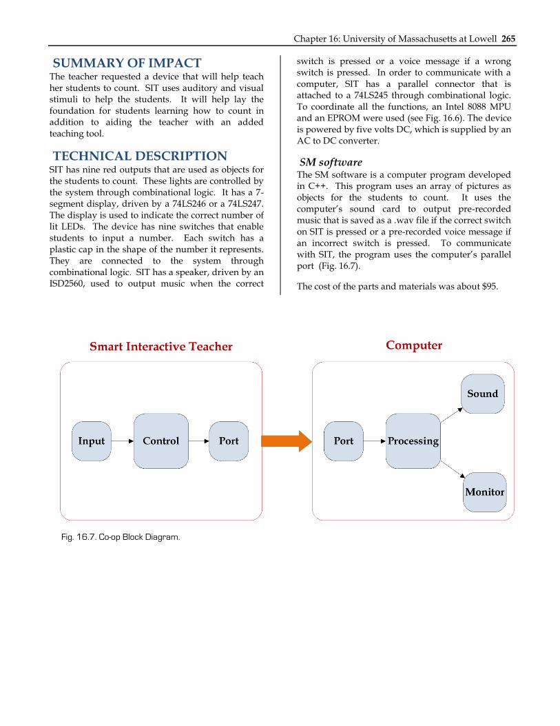
SIT can also connect to a computer to function with SM software, which is a computer program displaying a random number of animals for the student to identify. If the student chooses the correct number, the computer plays pre-recorded music and displays the number; if the student chooses incorrectly, then a voice message plays.
Chapter 16: University of Massachusetts at Lowell 265
SUMMARY OF IMPACT The teacher requested a device that will help teach her students to count. SIT uses auditory and visual stimuli to help the students. It will help lay the foundation for students learning how to count in addition to aiding the teacher with an added teaching tool.
TECHNICAL DESCRIPTION SIT has nine red outputs that are used as objects for the students to count. These lights are controlled by the system through combinational logic. It has a 7-segment display, driven by a 74LS246 or a 74LS247. The display is used to indicate the correct number of lit LEDs. The device has nine switches that enable students to input a number. Each switch has a plastic cap in the shape of the number it represents. They are connected to the system through combinational logic. SIT has a speaker, driven by an ISD2560, used to output music when the correct
switch is pressed or a voice message if a wrong switch is pressed. In order to communicate with a computer, SIT has a parallel connector that is attached to a 74LS245 through combinational logic. To coordinate all the functions, an Intel 8088 MPU and an EPROM were used (see Fig. 16.6). The device is powered by five volts DC, which is supplied by an AC to DC converter.
SM software The SM software is a computer program developed in C++. This program uses an array of pictures as objects for the students to count. It uses the computer’s sound card to output pre-recorded music that is saved as a .wav file if the correct switch on SIT is pressed or a pre-recorded voice message if an incorrect switch is pressed. To communicate with SIT, the program uses the computer’s parallel port (Fig. 16.7).
The cost of the parts and materials was about $95.
Fig. 16.7. Co-op Block Diagram.
266 NSF 2007 Engineering Senior Design Projects to Aid Persons with Disabilities
SOAP DISPENSER Designer: Mark Houseman
Client Coordinator: Bethany Campbell, Forestdale Memorial School, Malden, MA Supervising Professor: Chuck Maffeo Electrical Engineering Department
State University of Massachusetts at Lowell, Lowell, MA 01854
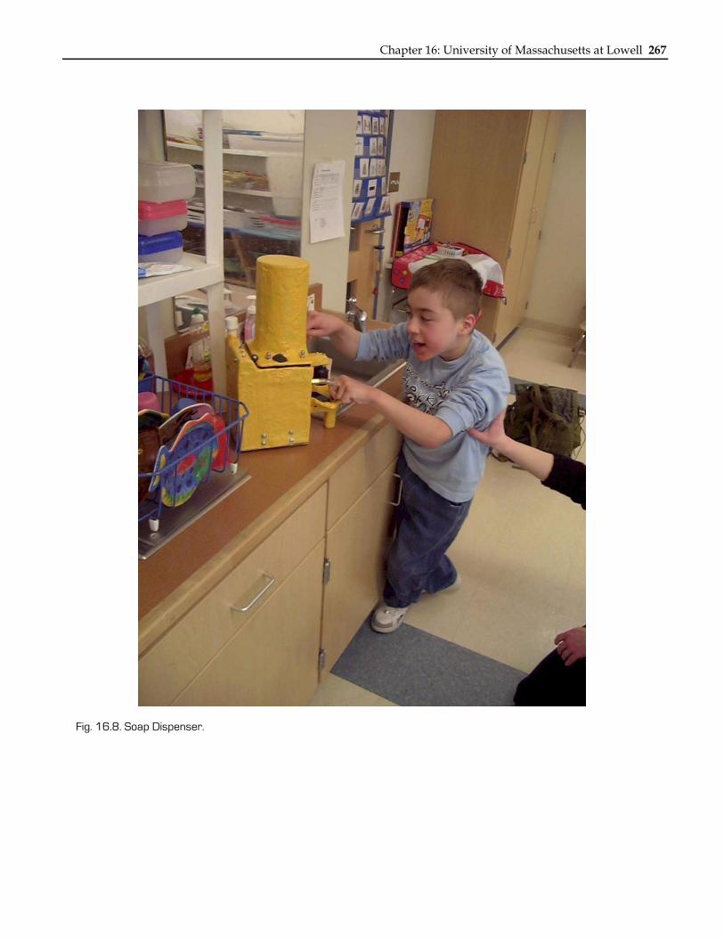
INTRODUCTION The Soap Dispenser (SD) is an automated soap distributor that provides an independently operable method of hand hygiene for a child with cerebral palsy (see Fig. 16.8). The SD uses an infrared sensor to detect motion, which triggers soap to dispense sideways into a shallow dish. The SD is easily used without rotating the palm upward. The device dispenses soap frequently, efficiently, and without adult assistance to the client. The device may be easily relocated.
SUMMARY OF IMPACT Using the SD, the client is able to wash his hands without taking up large amounts of the teachers’ time while in class. The device increases independence and promotes hygiene.
TECHNICAL DESCRIPTION The housing for the SD was made from: 1) 3/4“ wide aluminum tubing; 2) 26 gauge steel plating; 3) 16 gauge steel plating; and 4) fiberglass. The aluminum and steel plating were bolted together to form a sturdy housing, and the fiberglass was used to coat the housing. The steel and aluminum provide strength for the SD to survive impact, and the painted fiberglass provides water resistance and a finished look.
The dispenser has a 3300mAh battery, which allows for operation in locations without a nearby AC outlet. The battery must be recharged once a week by plugging an AC wall adapter into a power jack on the SD. The battery is a NiMH. It has the advantage over NiCd batteries of being unchanged
by the “memory effect,” which is when a battery loses overall potential by being recharged before it is completely drained. The charging circuit is monitored by a BQ2002T IC. The BQ2002T monitors the battery voltage with a voltage divider and the battery temperature with a thermistor (a heat sensitive resistor). When the battery is fully charged, the LED lights up and the BQ2002T trickle charges the battery to keep it at maximum charge.
Soap is dispensed when infrared light emitted from an LED reflects off the hand of the operator and becomes incident on a photosensitive transistor. A microcontroller senses a change in the voltage across the photosensitive transistor. The microcontroller provides power to: 1) an ISD1400 sound chip; 2) a solenoid valve; and 3) a linear solenoid. The ISD1400 sound chip plays a sound and then the solenoid valve opens, which enables soap to flow through the nozzle of the dispenser. The linear solenoid then pushes a spring pump for five repetitions. The spring pump moves the soap from a reservoir through a tube and out the nozzle.
When dispensing soap, the SD plays back a variety of Taz noises using the ISD1420 IC. The ISD chip is activated by the microcontroller and is activated prior to the linear solenoid. The ISD chip will play seven consecutive noises before beginning to repeat noises. The audio playback is turned on or off using a switch located on the back of the dispenser. The switch is easily used by an adult, but it cannot be used by a child.
The cost of the parts and materials was about $600.
Chapter 16: University of Massachusetts at Lowell 267
Fig. 16.8. Soap Dispenser.
268 NSF 2007 Engineering Senior Design Projects to Aid Persons with Disabilities
PORTABLE TOUCH-SCREEN COMMUNICATION DEVICE
Designers: Matthew B. Johnsen Client Coordinator: Cathy Reilly, Rockport, MA
Supervising Professor: Professor Alan Rux Electrical and Computer Engineering Department
State University of Massachusetts at Lowell Lowell, MA 01854
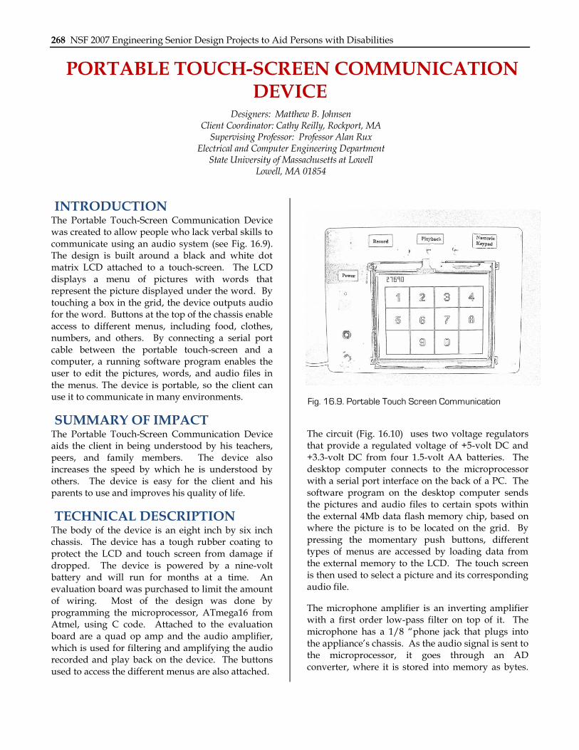
INTRODUCTION The Portable Touch-Screen Communication Device was created to allow people who lack verbal skills to communicate using an audio system (see Fig. 16.9). The design is built around a black and white dot matrix LCD attached to a touch-screen. The LCD displays a menu of pictures with words that represent the picture displayed under the word. By touching a box in the grid, the device outputs audio for the word. Buttons at the top of the chassis enable access to different menus, including food, clothes, numbers, and others. By connecting a serial port cable between the portable touch-screen and a computer, a running software program enables the user to edit the pictures, words, and audio files in the menus. The device is portable, so the client can use it to communicate in many environments.
SUMMARY OF IMPACT The Portable Touch-Screen Communication Device aids the client in being understood by his teachers, peers, and family members. The device also increases the speed by which he is understood by others. The device is easy for the client and his parents to use and improves his quality of life.
TECHNICAL DESCRIPTION The body of the device is an eight inch by six inch chassis. The device has a tough rubber coating to protect the LCD and touch screen from damage if dropped. The device is powered by a nine-volt battery and will run for months at a time. An evaluation board was purchased to limit the amount of wiring. Most of the design was done by programming the microprocessor, ATmega16 from Atmel, using C code. Attached to the evaluation board are a quad op amp and the audio amplifier, which is used for filtering and amplifying the audio recorded and play back on the device. The buttons used to access the different menus are also attached.
The circuit (Fig. 16.10) uses two voltage regulators that provide a regulated voltage of +5-volt DC and +3.3-volt DC from four 1.5-volt AA batteries. The desktop computer connects to the microprocessor with a serial port interface on the back of a PC. The software program on the desktop computer sends the pictures and audio files to certain spots within the external 4Mb data flash memory chip, based on where the picture is to be located on the grid. By pressing the momentary push buttons, different types of menus are accessed by loading data from the external memory to the LCD. The touch screen is then used to select a picture and its corresponding audio file.
The microphone amplifier is an inverting amplifier with a first order low-pass filter on top of it. The microphone has a 1/8 “phone jack that plugs into the appliance’s chassis. As the audio signal is sent to the microprocessor, it goes through an AD converter, where it is stored into memory as bytes.
Fig. 16.9. Portable Touch Screen Communication
Chapter 16: University of Massachusetts at Lowell 269
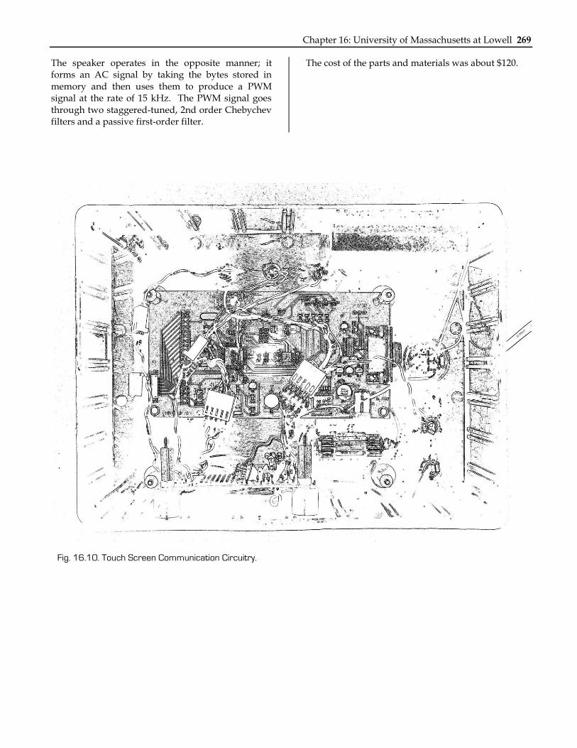
The speaker operates in the opposite manner; it forms an AC signal by taking the bytes stored in memory and then uses them to produce a PWM signal at the rate of 15 kHz. The PWM signal goes through two staggered-tuned, 2nd order Chebychev filters and a passive first-order filter.
The cost of the parts and materials was about $120.
Fig. 16.10. Touch Screen Communication Circuitry.
270 NSF 2007 Engineering Senior Design Projects to Aid Persons with Disabilities
MEDIA CONTROL CENTER Designer: Michael L. Bray
Client Coordinator: Deborah Plumer, Coastal Educational Collaborative, Salisbury, MA Supervising Professor: Jay Fu
Electrical and Computer Engineering Department University of Massachusetts at Lowell
Lowell, MA 01854
INTRODUCTION The Media Control Center (MCC) was created for individuals with disabilities at an educational collaborative. The MCC was designed to: 1) provide a computer-based solution to view photos; 2) provide an easy way to handle a growing photo library; and 3) give clients an opportunity to run slideshows independently. The MCC provides an interface box to a PC that runs the MCC application software. The application software monitors the interface box over the parallel port and responds to button presses by opening photos and moving back and forth between photos in the library. The photos are displayed on a wall through the LCD projector. To accommodate for clients with varying degrees of motor skills, the MCC provides three 1/8” jacks, allowing any button with a 1/8” jack to be connected, such as AbleNet’s “Big Red Switch” and “Jellybean” style buttons.
SUMMARY OF IMPACT The ability to customize the button size allows individuals with a wide range of skills to operate the device. The MCC provides the clients with the ability to view photos unassisted, which gives the clients a feeling of independence, and allows staff members the ability to assist others in the facility. The device also accommodates the facility’s large library of photographs.
TECHNICAL DESCRIPTION The MCC interface box contains three 1/8” stereo jacks that allow the user to connect a standard
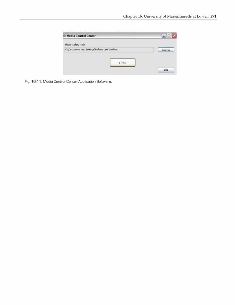
“Jellybean” style input device. Button presses are latched and read by the MCC application software via the parallel port. The application software, written in C++, was designed to run on the Windows 2000/XP platform and utilizes a third-party parallel port driver to access the MCC interface box. The software (see Fig. 16.11) allows the users to select the source location of their photo library, and it stores this path in the Windows Registry to be used as the default. This path can be updated at any time, which gives the clients the flexibility to move and sort their library as they desire. The application looks for files containing the JPG extension. When the user presses the “Start” button, the application initializes the parallel port and begins to monitor the button states.
The application checks for any new button presses every 250 ms when triggered by a Windows Timer event. The associated event handler parses the data read back and performs the appropriate action. These actions include: 1) starting the photo viewer; 2) displaying the next photo; and 3) displaying the previous photo. As the user traverses the directory, file paths are stored in a Standard Template Library (STL) vector of CString objects. These file paths are traversed by the use of a vector iteration. Unlike a standard array, an STL vector grows on its own, reallocating memory as needed. Images are opened on the screen, utilizing the default windows image viewer, and they are then displayed on the wall via the LCD projector.
The cost of the parts and materials was about $65.
Chapter 16: University of Massachusetts at Lowell 271
Fig. 16.11. Media Control Center Application Software.
272 NSF 2007 Engineering Senior Design Projects to Aid Persons with Disabilities
TACTILE IMAGER Designer: Nicholas H. Brunelle
Client Coordinator: Thomas David, Malden Elementary School, Malden, MA Supervising Professor: Alan Rux
University of Massachusetts at Lowell Lowell, MA 01841
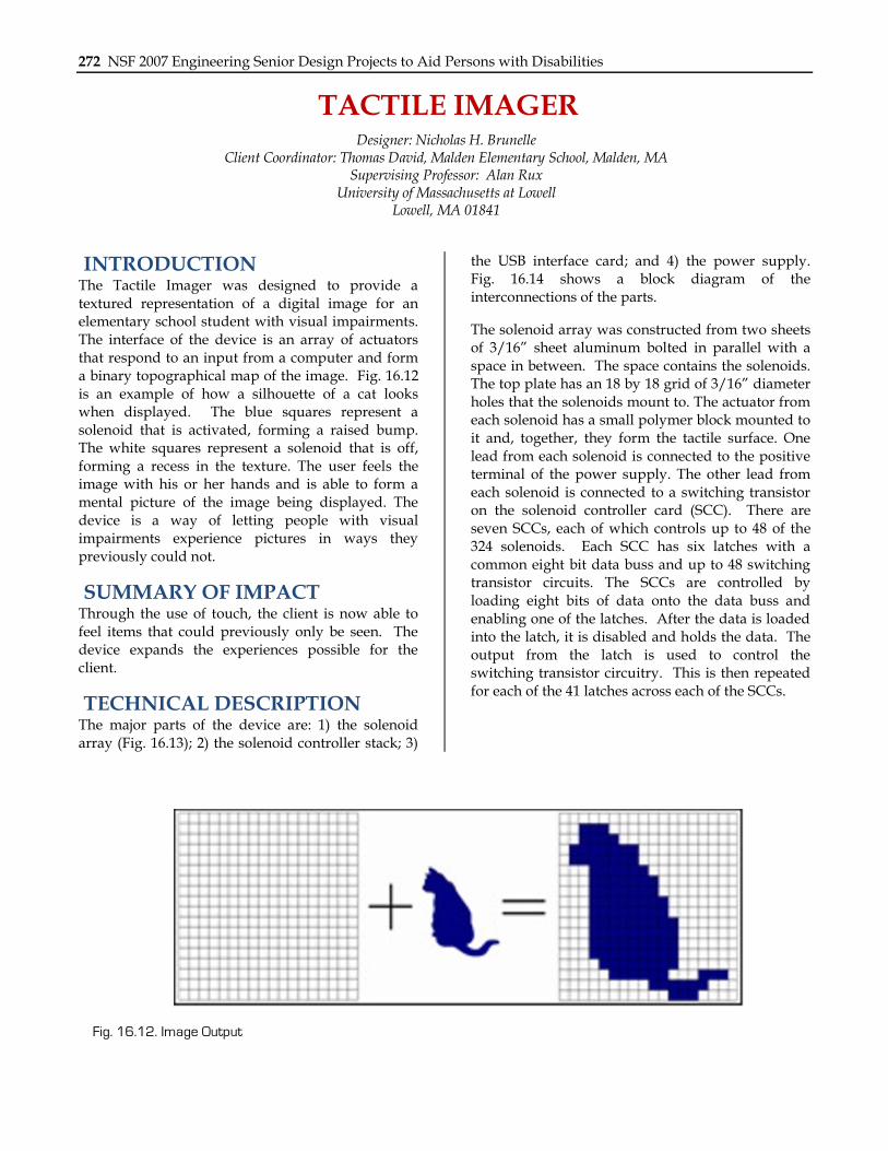
INTRODUCTION The Tactile Imager was designed to provide a textured representation of a digital image for an elementary school student with visual impairments. The interface of the device is an array of actuators that respond to an input from a computer and form a binary topographical map of the image. Fig. 16.12 is an example of how a silhouette of a cat looks when displayed. The blue squares represent a solenoid that is activated, forming a raised bump. The white squares represent a solenoid that is off, forming a recess in the texture. The user feels the image with his or her hands and is able to form a mental picture of the image being displayed. The device is a way of letting people with visual impairments experience pictures in ways they previously could not.
SUMMARY OF IMPACT Through the use of touch, the client is now able to feel items that could previously only be seen. The device expands the experiences possible for the client.
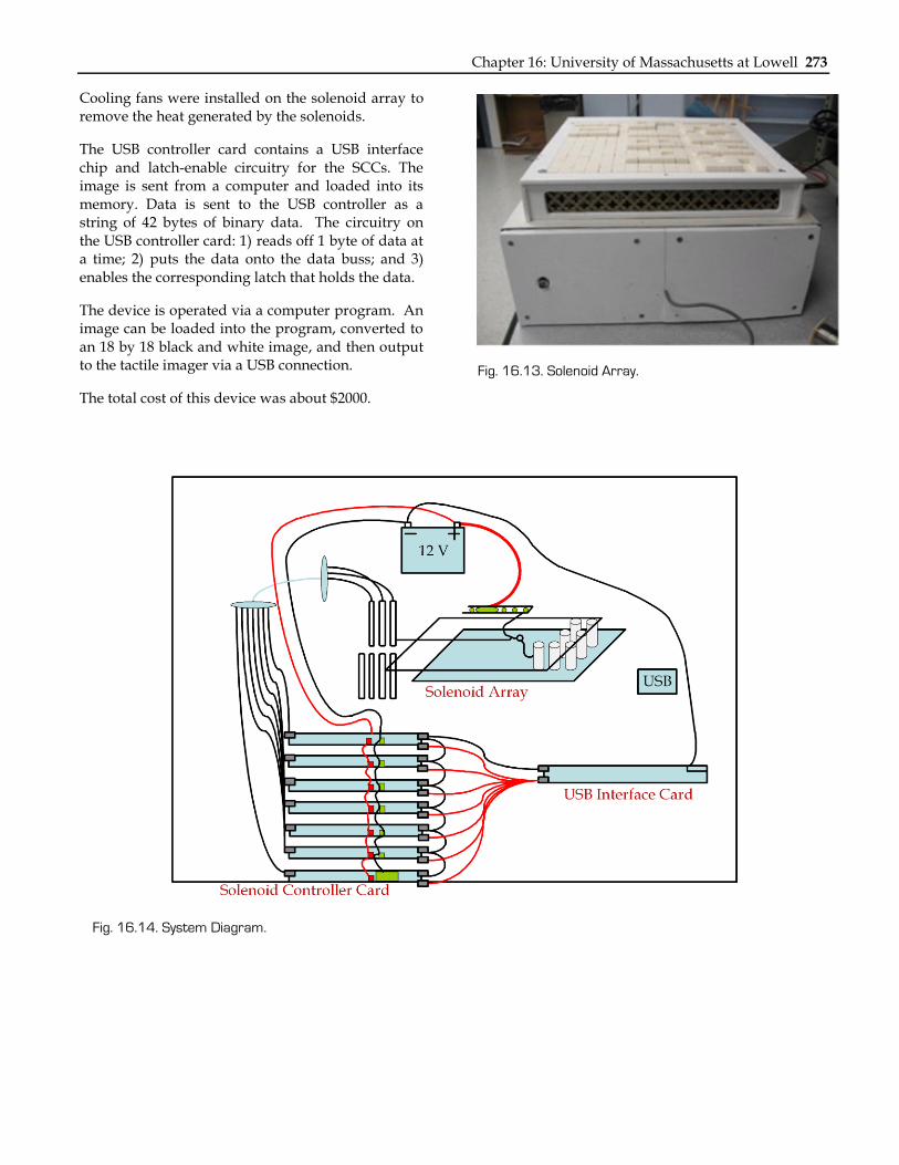
TECHNICAL DESCRIPTION The major parts of the device are: 1) the solenoid array (Fig. 16.13); 2) the solenoid controller stack; 3)
the USB interface card; and 4) the power supply. Fig. 16.14 shows a block diagram of the interconnections of the parts.
The solenoid array was constructed from two sheets of 3/16” sheet aluminum bolted in parallel with a space in between. The space contains the solenoids. The top plate has an 18 by 18 grid of 3/16” diameter holes that the solenoids mount to. The actuator from each solenoid has a small polymer block mounted to it and, together, they form the tactile surface. One lead from each solenoid is connected to the positive terminal of the power supply. The other lead from each solenoid is connected to a switching transistor on the solenoid controller card (SCC). There are seven SCCs, each of which controls up to 48 of the 324 solenoids. Each SCC has six latches with a common eight bit data buss and up to 48 switching transistor circuits. The SCCs are controlled by loading eight bits of data onto the data buss and enabling one of the latches. After the data is loaded into the latch, it is disabled and holds the data. The output from the latch is used to control the switching transistor circuitry. This is then repeated for each of the 41 latches across each of the SCCs.
Fig. 16.12. Image Output
Chapter 16: University of Massachusetts at Lowell 273
Cooling fans were installed on the solenoid array to remove the heat generated by the solenoids.
The USB controller card contains a USB interface chip and latch-enable circuitry for the SCCs. The image is sent from a computer and loaded into its memory. Data is sent to the USB controller as a string of 42 bytes of binary data. The circuitry on the USB controller card: 1) reads off 1 byte of data at a time; 2) puts the data onto the data buss; and 3) enables the corresponding latch that holds the data.
The device is operated via a computer program. An image can be loaded into the program, converted to an 18 by 18 black and white image, and then output to the tactile imager via a USB connection.
The total cost of this device was about $2000.
Fig. 16.13. Solenoid Array.
Fig. 16.14. System Diagram.
274 NSF 2007 Engineering Senior Design Projects to Aid Persons with Disabilities
AUDIO MIXER Designer: Phong K. Dinh
Client Coordinator: Tony Chavez and Keith Casavoy Supervising Professor: Prof. Alan Rux
Electrical and Computer Engineering Department University of Massachusetts, Lowell
Lowell, MA 01854
INTRODUCTION The AMVI (Fig. 16.15) was designed to enable a client to control an audio mixer. The client requested the ability to control the volumes or faders of each individual channel through sliding potentiometers. Large rocker switches and large knobs were used to maximize control and stability of the system. The device allows the client to fully control every aspect of the audio mixer.
SUMMARY OF IMPACT The device provides the client with increased independence and enjoyment by allowing him control of the audio mixer. The switches and knobs help him locate the controlling devices more quickly. The built-in micro-switches inside each sliding potentiometer also allow the client to simultaneously control mixer functions, which he could not do previously.
TECHNICAL DESCRIPTION The AMVI is a modified version of the Arrakis 150SC Console. The audio mixer is powered by an AC to DC converter. The power converter converts 120-volts AC to an adjustable 12-volt DC output. The console consists of five input channels. Within each channel are two different sections: A and B. The total number of inputs for the AMVI is ten. The inputs for each channel are located directly on top of the audio mixer. The inputs include eight phono jacks and two microphone XLR female connectors. The controlling interfaces for the AMVI are six sliding potentiometers and seven rocker switches.
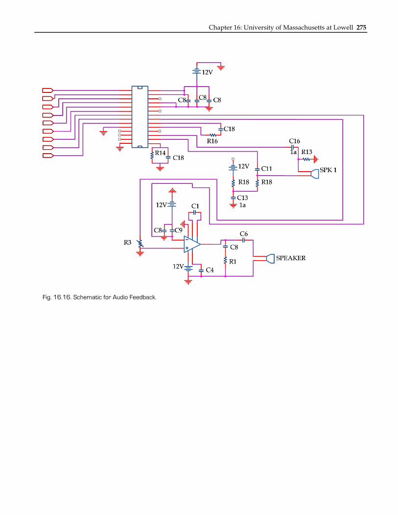
The audio feedback circuit for the AMVI (Fig. 16.16) consists of a Basic Stamp 2E microcontroller from
Parallax. A voice recorder chip, ISD 2560, was used to process and store prerecorded messages. The messages tell the client the status of the mixer. The ISD 2560 provides a large sampling frequency (8 kHz/sec). The ISD 2560 has 60 seconds of record and playback time.
When in operating the AMVI, the six rocker switches enable the individual reed relays to be energized so that sound or music is output to the program buss. The Basic Stamp 2E also plays back the stored messages through the ISD 2560. The messages are heard through the phono jacks, which are located directly in front of the client. The audio feedback tells the current status of a particular channel. Pressing the status pushbutton plays the entire status of every channel on the audio mixer. The status pushbutton is isolated from the other buttons.
The cost of the parts and materials was about $1500.
Fig. 16.15. Audio Mixer.
Chapter 16: University of Massachusetts at Lowell 275
Fig. 16.16. Schematic for Audio Feedback.
276 NSF 2007 Engineering Senior Design Projects to Aid Persons with Disabilities
WIRELESS REMOTE CONTROL WHEELCHAIR TRAINER
Designer: Run Ron
Client Coordinator: Bonnie Paulino, Franciscan Hospital for Children, Boston, MA Supervising Professor: Prof. Alan Rux
Electrical and Computer Engineering Department University of Massachusetts at Lowell
Lowell, MA 01854
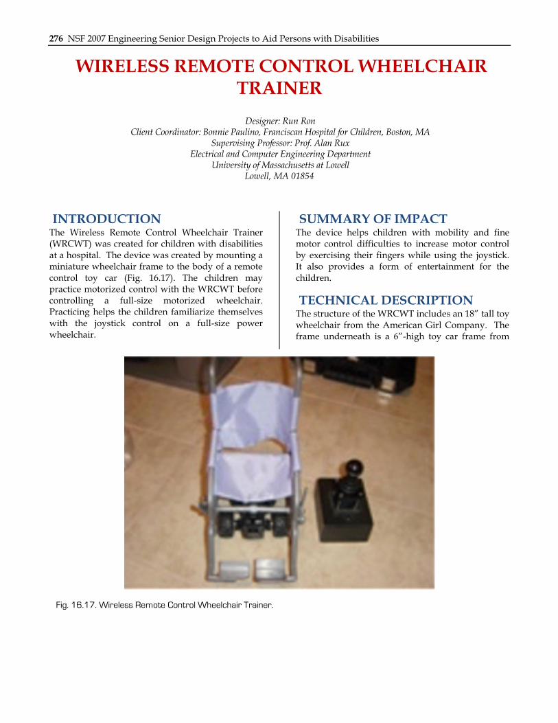
INTRODUCTION The Wireless Remote Control Wheelchair Trainer (WRCWT) was created for children with disabilities at a hospital. The device was created by mounting a miniature wheelchair frame to the body of a remote control toy car (Fig. 16.17). The children may practice motorized control with the WRCWT before controlling a full-size motorized wheelchair. Practicing helps the children familiarize themselves with the joystick control on a full-size power wheelchair.
SUMMARY OF IMPACT The device helps children with mobility and fine motor control difficulties to increase motor control by exercising their fingers while using the joystick. It also provides a form of entertainment for the children.
TECHNICAL DESCRIPTION The structure of the WRCWT includes an 18” tall toy wheelchair from the American Girl Company. The frame underneath is a 6”-high toy car frame from
Fig. 16.17. Wireless Remote Control Wheelchair Trainer.
Chapter 16: University of Massachusetts at Lowell 277
New Bright Company. The two frames were mounted together with two 3/8” screws. Both the wheelchair and remote control have a power switch.
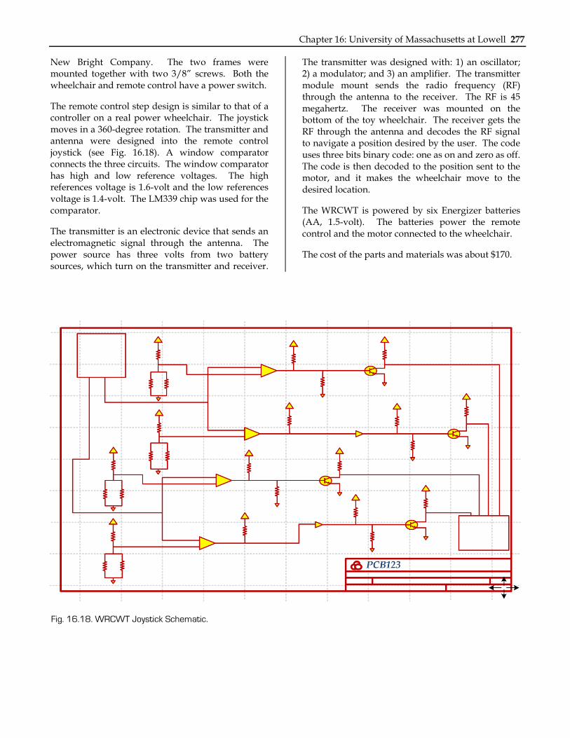
The remote control step design is similar to that of a controller on a real power wheelchair. The joystick moves in a 360-degree rotation. The transmitter and antenna were designed into the remote control joystick (see Fig. 16.18). A window comparator connects the three circuits. The window comparator has high and low reference voltages. The high references voltage is 1.6-volt and the low references voltage is 1.4-volt. The LM339 chip was used for the comparator.
The transmitter is an electronic device that sends an electromagnetic signal through the antenna. The power source has three volts from two battery sources, which turn on the transmitter and receiver.
The transmitter was designed with: 1) an oscillator; 2) a modulator; and 3) an amplifier. The transmitter module mount sends the radio frequency (RF) through the antenna to the receiver. The RF is 45 megahertz. The receiver was mounted on the bottom of the toy wheelchair. The receiver gets the RF through the antenna and decodes the RF signal to navigate a position desired by the user. The code uses three bits binary code: one as on and zero as off. The code is then decoded to the position sent to the motor, and it makes the wheelchair move to the desired location.
The WRCWT is powered by six Energizer batteries (AA, 1.5-volt). The batteries power the remote control and the motor connected to the wheelchair.
The cost of the parts and materials was about $170.
Fig. 16.18. WRCWT Joystick Schematic.
278 NSF 2007 Engineering Senior Design Projects to Aid Persons with Disabilities
HANDS DOWN, SIT UP STRAIGHT Designer: Shawn P. Garvey
Supervising Professor: Alan Rux Electrical and Computer Engineering Department
University of Massachusetts Lowell Lowell, MA 01850
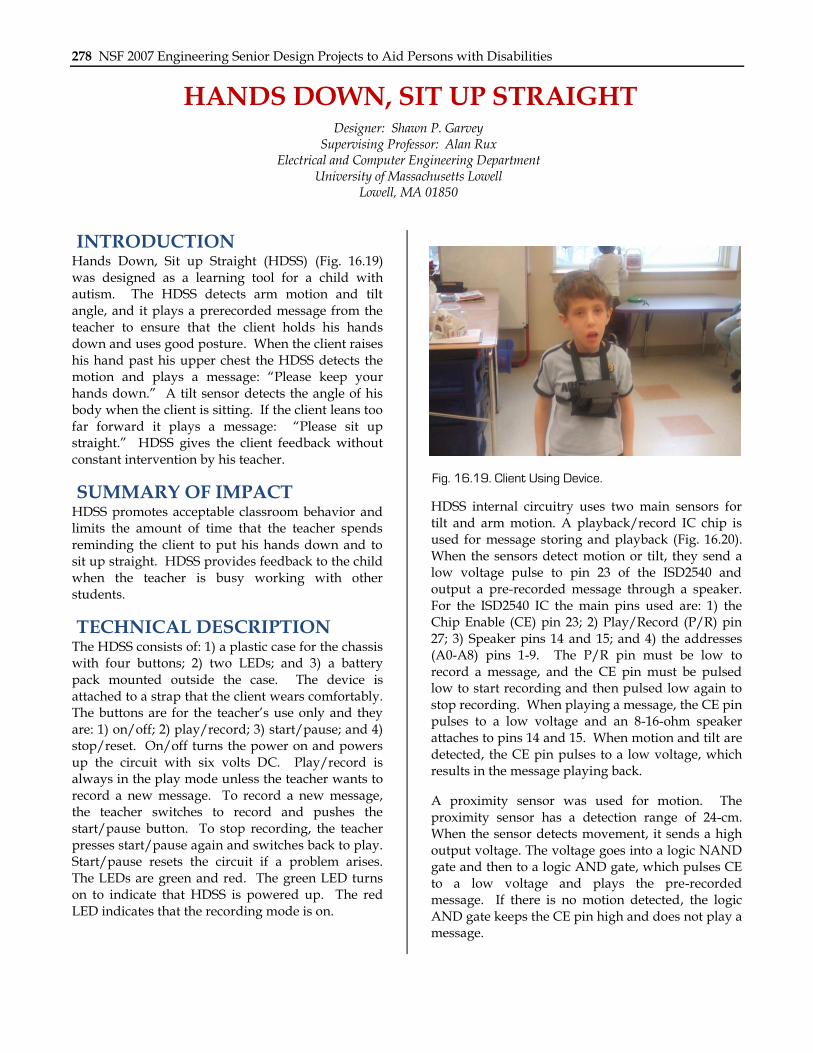
INTRODUCTION Hands Down, Sit up Straight (HDSS) (Fig. 16.19) was designed as a learning tool for a child with autism. The HDSS detects arm motion and tilt angle, and it plays a prerecorded message from the teacher to ensure that the client holds his hands down and uses good posture. When the client raises his hand past his upper chest the HDSS detects the motion and plays a message: “Please keep your hands down.” A tilt sensor detects the angle of his body when the client is sitting. If the client leans too far forward it plays a message: “Please sit up straight.” HDSS gives the client feedback without constant intervention by his teacher.
SUMMARY OF IMPACT HDSS promotes acceptable classroom behavior and limits the amount of time that the teacher spends reminding the client to put his hands down and to sit up straight. HDSS provides feedback to the child when the teacher is busy working with other students.
TECHNICAL DESCRIPTION The HDSS consists of: 1) a plastic case for the chassis with four buttons; 2) two LEDs; and 3) a battery pack mounted outside the case. The device is attached to a strap that the client wears comfortably. The buttons are for the teacher’s use only and they are: 1) on/off; 2) play/record; 3) start/pause; and 4) stop/reset. On/off turns the power on and powers up the circuit with six volts DC. Play/record is always in the play mode unless the teacher wants to record a new message. To record a new message, the teacher switches to record and pushes the start/pause button. To stop recording, the teacher presses start/pause again and switches back to play. Start/pause resets the circuit if a problem arises. The LEDs are green and red. The green LED turns on to indicate that HDSS is powered up. The red LED indicates that the recording mode is on.
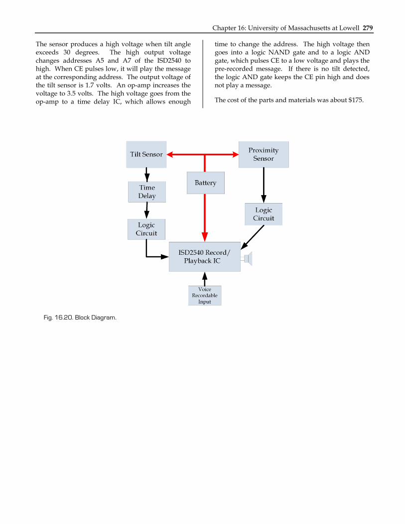
HDSS internal circuitry uses two main sensors for tilt and arm motion. A playback/record IC chip is used for message storing and playback (Fig. 16.20). When the sensors detect motion or tilt, they send a low voltage pulse to pin 23 of the ISD2540 and output a pre-recorded message through a speaker. For the ISD2540 IC the main pins used are: 1) the Chip Enable (CE) pin 23; 2) Play/Record (P/R) pin 27; 3) Speaker pins 14 and 15; and 4) the addresses (A0-A8) pins 1-9. The P/R pin must be low to record a message, and the CE pin must be pulsed low to start recording and then pulsed low again to stop recording. When playing a message, the CE pin pulses to a low voltage and an 8-16-ohm speaker attaches to pins 14 and 15. When motion and tilt are detected, the CE pin pulses to a low voltage, which results in the message playing back.
A proximity sensor was used for motion. The proximity sensor has a detection range of 24-cm. When the sensor detects movement, it sends a high output voltage. The voltage goes into a logic NAND gate and then to a logic AND gate, which pulses CE to a low voltage and plays the pre-recorded message. If there is no motion detected, the logic AND gate keeps the CE pin high and does not play a message.
Fig. 16.19. Client Using Device.
Chapter 16: University of Massachusetts at Lowell 279
The sensor produces a high voltage when tilt angle exceeds 30 degrees. The high output voltage changes addresses A5 and A7 of the ISD2540 to high. When CE pulses low, it will play the message at the corresponding address. The output voltage of the tilt sensor is 1.7 volts. An op-amp increases the voltage to 3.5 volts. The high voltage goes from the op-amp to a time delay IC, which allows enough
time to change the address. The high voltage then goes into a logic NAND gate and to a logic AND gate, which pulses CE to a low voltage and plays the pre-recorded message. If there is no tilt detected, the logic AND gate keeps the CE pin high and does not play a message.
The cost of the parts and materials was about $175.
Fig. 16.20. Block Diagram.
280 NSF 2007 Engineering Senior Design Projects to Aid Persons with Disabilities
SMART HAT Designers: Thomas M. Donigan
Supervising Professor: Prof. Alan Rux Electrical and Computer Engineering Department
University of Massachusetts, Lowell Lowell, MA 01854
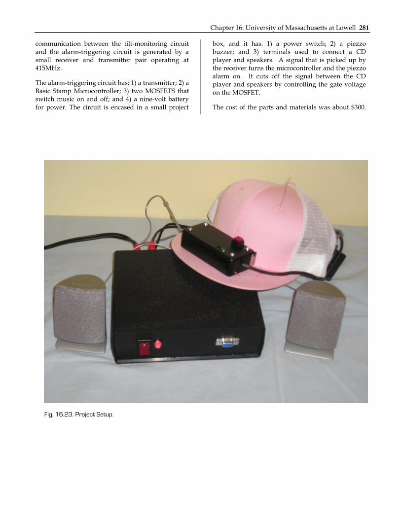
INTRODUCTION The Smart Hat was designed as a learning tool to help an elementary school student with spina bifida and down syndrome pay more attention in school by reminding her to keep her head in an upright position. The device uses a low-g accelerometer as a two-axis tilt sensor mounted on a baseball cap (see Fig. 16.23). The Smart Hat detects when the client’s head is no longer in an upright position, and it sends a signal through a radio frequency (RF) link operating at 415MHz to an alarm system. The alarm system simultaneously turns off a music player and sounds a pulsating alarm. The alarm stops and the CD music is turned back on when the SH detects the client’s head is once again in an upright position.
SUMMARY OF IMPACT The device encourages appropriate classroom behavior and reminds the client to pay attention in class. The device also decreases the amount of time that the teachers spend reminding the client to attend to tasks. The device incorporates the client’s interest in music.
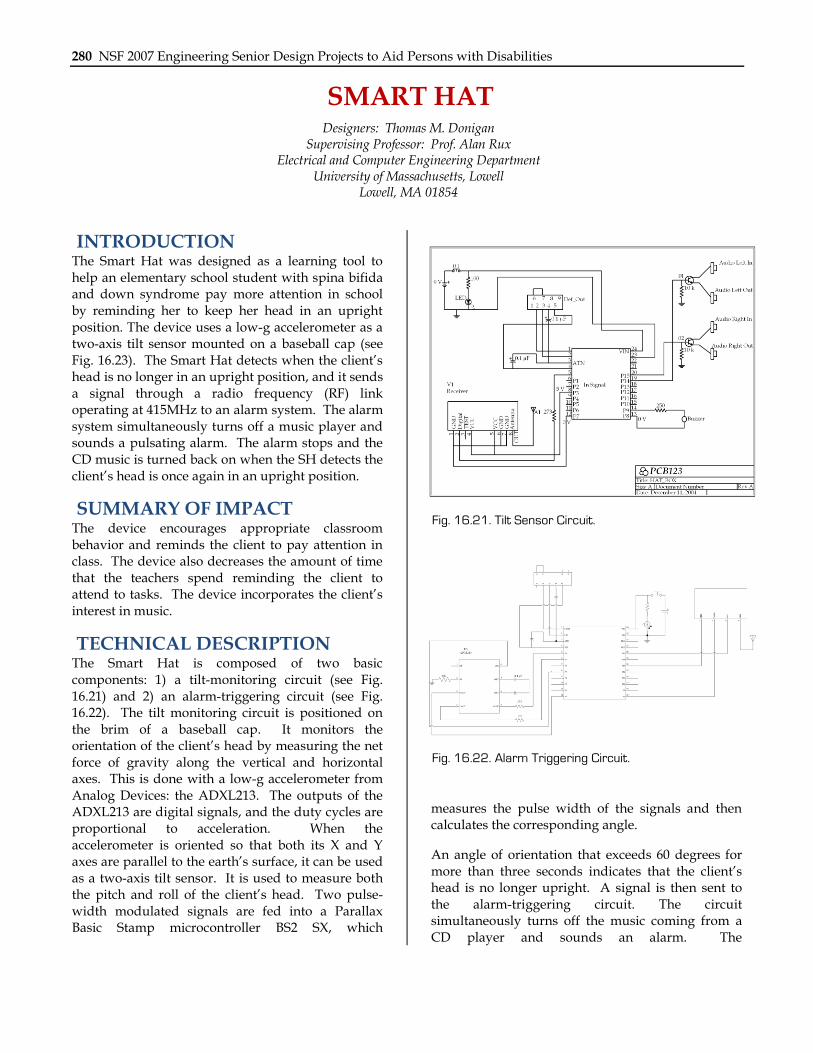
TECHNICAL DESCRIPTION The Smart Hat is composed of two basic components: 1) a tilt-monitoring circuit (see Fig. 16.21) and 2) an alarm-triggering circuit (see Fig. 16.22). The tilt monitoring circuit is positioned on the brim of a baseball cap. It monitors the orientation of the client’s head by measuring the net force of gravity along the vertical and horizontal axes. This is done with a low-g accelerometer from Analog Devices: the ADXL213. The outputs of the ADXL213 are digital signals, and the duty cycles are proportional to acceleration. When the accelerometer is oriented so that both its X and Y axes are parallel to the earth’s surface, it can be used as a two-axis tilt sensor. It is used to measure both the pitch and roll of the client’s head. Two pulse-width modulated signals are fed into a Parallax Basic Stamp microcontroller BS2 SX, which
measures the pulse width of the signals and then calculates the corresponding angle.
An angle of orientation that exceeds 60 degrees for more than three seconds indicates that the client’s head is no longer upright. A signal is then sent to the alarm-triggering circuit. The circuit simultaneously turns off the music coming from a CD player and sounds an alarm. The
Fig. 16.21. Tilt Sensor Circuit.
Fig. 16.22. Alarm Triggering Circuit.
Chapter 16: University of Massachusetts at Lowell 281
communication between the tilt-monitoring circuit and the alarm-triggering circuit is generated by a small receiver and transmitter pair operating at 415MHz.
The alarm-triggering circuit has: 1) a transmitter; 2) a Basic Stamp Microcontroller; 3) two MOSFETS that switch music on and off; and 4) a nine-volt battery for power. The circuit is encased in a small project
box, and it has: 1) a power switch; 2) a piezzo buzzer; and 3) terminals used to connect a CD player and speakers. A signal that is picked up by the receiver turns the microcontroller and the piezzo alarm on. It cuts off the signal between the CD player and speakers by controlling the gate voltage on the MOSFET.
The cost of the parts and materials was about $300.
Fig. 16.23. Project Setup.
282 NSF 2007 Engineering Senior Design Projects to Aid Persons with Disabilities