Chemical Engineering at Orbital ATK Shelby Healy, Justin Pancoast Peer Review: Scott Mildenhall March 22, 2016 University of Utah Chemical Engineering Seminar https://ntrs.nasa.gov/search.jsp?R=20160004383 2018-06-08T01:44:23+00:00Z
• Goal: Give a snapshot of what a chemical engineer might expect to do in
the aerospace industry through the experiences of two different
engineers at Orbital ATK
• Company description
• Product description
• Shelby’s experiences
• Justin’s experiences
1
About Orbital ATK
• $4.5 billion global aerospace and defense systems company
• Industry leader in government, defense and commercial markets
• Employs ~12,500 people, including ~4,300 engineers and scientists
• Major locations in 8 states (Virginia, Maryland, West Virginia, Minnesota, Missouri, Utah, Arizona and California), plus smaller locations and employees based in another 12 states
• Corporate headquarters in Dulles, Virginia
• This is a very exciting time for Orbital ATK. This is a unique strategic convergence of two companies that have worked together for more than 25 years
• Orbital ATK is financially strong and highly competitive in the aerospace and defense sector based on the company’s focus on the innovation, reliability, and affordability of its products
AE is the technical authority for his discipline. The AE’s charter is to ensure
performance requirements are properly dispersed and met and providing
boundary conditions or performance requirements for component /vehicle
design.
Design Engineer
(DE)
Design
Engineering
DE is the technical owner of his/her component. The DE’s charter is to
define the engineering requirements necessary for their design area to
perform within specification & often times statistical expectation.
Manufacturing Engineer
(ME)
Operations ME is the process owner of his/her component. The ME’s charter is to define
the manufacturing process that meets or exceeds both the engineering and
processability requirements levied by the DE & Orbital ATK.
Quality Engineer
(QE)
Quality QE is the inspection process owner of his/her component. The QE’s charter
is to define the proper inspection steps and methodologies that ensure the
design intent, engineering specifications and process requirements are
satisfied.
Systems Engineer
(SE)
Science and
Engineering
Derive system level requirements, system architecture, perform functional
analysis, trade studies, verification of customer requirements
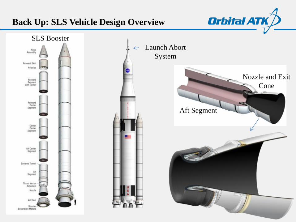
SLS Program Summary
Launch
Abort
System
Heavy Lift Space Launch System
MSFC Engineering
Support Materials
Testing Laboratory
CCiCap-020v11
1st Stage Transit by
Rail
RPSF: 1st
Stage Aft Assyoff critical path
VAB: Assembly and Testing
2nd Stage Transit by
Ship
1st Stage Stacking12 days
2nd Stage Stacking
5 days
Integrated Testing
IST #1: 4 daysIST #2: 3 days
Space VehicleMate3 days
Vehicle Closeouts
3 days
LC39: Pad Activities and
Launch5 days
(5 day refurb)
Liberty Ground Ops Process Flow: 40 Days
O&C: Crew/Service
Module Assembly
off critical path
MLP/Crawler
LCC
Astrotech: MLAS ProcessingIntegration, Fuel load
Off critical path
Recovery & RefurbReturn to O&C
Mission Ops
MLAS Demonstration
Vehicle Assembly Building
Rotating Processing
and Surge Facility
Rocket
Motor
Test
Facility
Aft Booster
Stacking
in VAB
Booster
Assembly
Integration
Stage
Avionics
Thrust Vector Control
Casting
Core
6
Booster Overview
Liner provides bonding between
propellant and internal insulation
Liner/insulation bond is primarily a
physical bond (insulation has a
textured-surface to enhance bonding)
Liner/propellant bond is primarily a
chemical bond
Liner, like insulation and propellant,
is a viscoelastic material: mechanical
response changes based on the rate
and time period of applied load
Propellant
Liner
Insulation
Steel Case
Liner
Castable
InhibitorPropellant Surface
Burn Inhibitor (aft
face of forward and
center segments)
LinerPropellant-to-insulation
Bond System (full
length of interior of each
segment and igniter)
9
• Hand line application of SLS forward segment requires one medium size liner mix
• Applied with segment in horizontal position
• Sling line application of SLS segments requires two large liner mixes
• Applied with segment in vertical position
Liner Mixing & Application
10
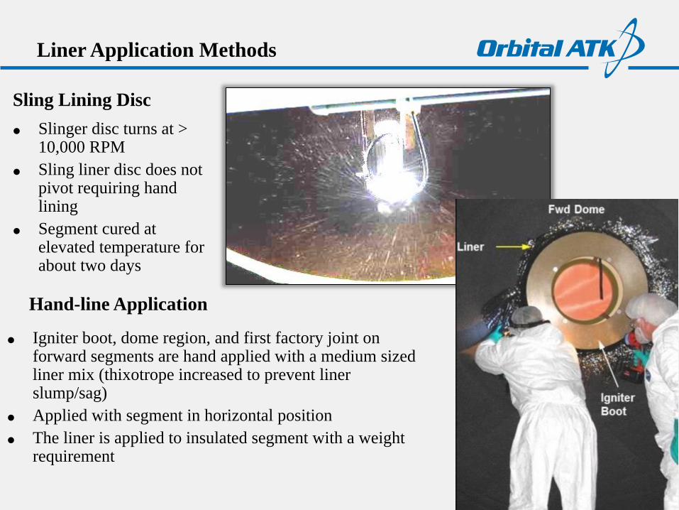
Sling Lining Disc
Slinger disc turns at >10,000 RPM
Sling liner disc does not pivot requiring hand lining
Segment cured at elevated temperature for about two days
Liner Application Methods
Hand-line Application
Igniter boot, dome region, and first factory joint on forward segments are hand applied with a medium sized liner mix (thixotrope increased to prevent liner slump/sag)
Applied with segment in horizontal position
The liner is applied to insulated segment with a weight requirement
Inspected for “full coverage”
• Thickness not measured: weight requirement with
known surface area
• Prior to liner cure, an operator is lowered into segment
(personned basket) to verify full coverage
• Liner voids are reworked if found
• After liner pre-cure, operators and inspectors are
lowered into the segment to verify full coverage
• Any liner voids found are repaired with liner saved from
the liner used for sling application
• Repair liner will cure during segment pre-heat prior to
propellant cast
Liner Post-Cure Inspection - OLD
Liner Inspection
The segment must be cast with propellant within about three weeks after liner
cure to ensure adequate liner cure potential remaining
During this time witness panels are tested to verify tensile strength of the
liner/insulation system
Liner Post-Cure Inspection – NEW
Flash Thermography
Inspection – Liner Witness to Offgassing
Pinhole, exposed insulation
Micro-CT
14
• Witness panels are processed side-by-side with the segments
• Segment witness panels include tensile buttons and peel strips that test the critical bond interfaces
Liner Witness Panels
Liner-Propellant Bondline
Liner-Insulation Bondline
Witness Panels – Screed vs Sling
• Motor experiences sling line application while witness panels experience
screed application
Witness Panels – Screed vs Sling
• Effort to sling line panels showed that it is more difficult to test uneven
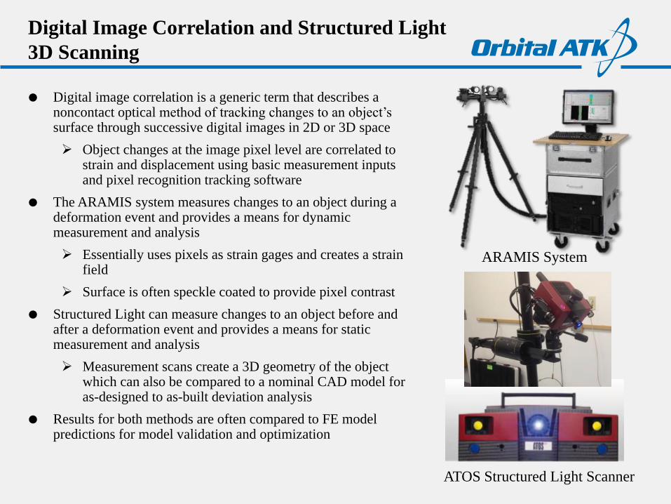
Digital image correlation is a generic term that describes a noncontact optical method of tracking changes to an object’s surface through successive digital images in 2D or 3D space
Object changes at the image pixel level are correlated to strain and displacement using basic measurement inputs and pixel recognition tracking software
The ARAMIS system measures changes to an object during a deformation event and provides a means for dynamic measurement and analysis
Essentially uses pixels as strain gages and creates a strain field
Surface is often speckle coated to provide pixel contrast
Structured Light can measure changes to an object before and after a deformation event and provides a means for static measurement and analysis
Measurement scans create a 3D geometry of the object which can also be compared to a nominal CAD model for as-designed to as-built deviation analysis
Results for both methods are often compared to FE model predictions for model validation and optimization
ATOS Structured Light Scanner
ARAMIS System
Basics of ARAMIS Dynamic Deformation
Measurement
27
facet size
facet step
fovx 465.9 [mm] 18.343 [in]
computation size
total points with 12M cameras
strain sensitivity [%]
strain sensitivity [ue]
equivalent gage length 4.55 [mm] 0.179 [in]
in plane displacement sensitivity 3.11 [um] 0.000 [in]
out of plane displacement sensitivity 15.53 [um] 0.001 [in]
Point Spacing 1.14 [mm] 0.045 [in]
Dot Size 0.57 [mm] 0.022 [in]
Presets
Expected Results
125829
30
10
5
0.011
111
ARAMIS equipment is highly mobile and can be tailored to lab and in-field measurements
ARAMIS software allocates coordinates to the image pixels
The first image represents the undeformed state to which all images are compared for deformation calculations
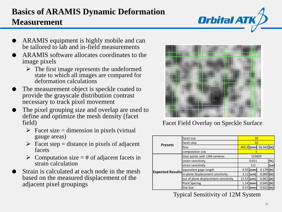
The measurement object is speckle coated to provide the grayscale distribution contrast necessary to track pixel movement
The pixel grouping size and overlap are used to define and optimize the mesh density (facet field)
Facet size = dimension in pixels (virtual gauge areas)
Facet step = distance in pixels of adjacent facets
Computation size = # of adjacent facets in strain calculation
Strain is calculated at each node in the mesh based on the measured displacement of the adjacent pixel groupings
Typical Sensitivity of 12M System
Facet Field Overlay on Speckle Surface
ARAMIS Application: PLI FEA Model and
Material Validation
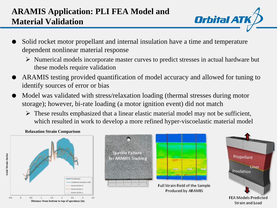
Solid rocket motor propellant and internal insulation have a time and temperature
dependent nonlinear material response
Numerical models incorporate master curves to predict stresses in actual hardware but
these models require validation
ARAMIS testing provided quantification of model accuracy and allowed for tuning to
identify sources of error or bias
Model was validated with stress/relaxation loading (thermal stresses during motor
storage); however, bi-rate loading (a motor ignition event) did not match
These results emphasized that a linear elastic material model may not be sufficient,
which resulted in work to develop a more refined hyper-viscoelastic material model
28
Relaxation Strain Comparison
ARAMIS Application: SLS Booster
FSTA-1 &-2 Forward Skirt Structural Testing
SLS ultimate assent loads are approximately 40% higher than
historical shuttle loads; however, NASA wants to use the
heritage space shuttle forward skirt hardware instead of
designing a new structure
The booster transfers load to the core vehicle through the
forward skirt thrust post
Analysis indicated that the shuttle forward skirt would not
meet structural safety factor requirements so testing was
commissioned to identify actual capability
ARAMIS testing was able to provide data when strain gages
failed, identify localized high strain near joint welds, and
strain at the failure initiation point on the thrust post
Proof testing followed by a burst test was performed on NASA’s Advanced Booster
composite case that had been intentionally damaged to varying degrees
Risk reduction effort to verify structural safety margins of a damaged motor at
varying internal pressures
Damage levels were based on the critical impact damage on a composite case that
could go undetected
ARAMIS testing was used to image the damage impact sites where it was not possible to
use strain gages
Able to detect and correlate unique strain irregularities during the proof and burst
tests, but most importantly, was able to show that local strain had not been affected
significantly by intentional damage
30
Some traditional strain gages failed mid-test
ARAMIS strain
did not fail
Impact Site:
Radial Displacement
Contour Plot with
Max Principle Strain
Vector Overlay
Basics of Structured Light (TRITOP/ATOS) Static
Deformation Measurement
31
The Structured Light system is highly mobile and can be customized for lab and field testing
Structured Light scanning collects full-field 3D surface data of as-built geometry by using stereo cameras to capture a fringe pattern sent out from the central projector
Software triangulates all of the surface data using changes in pixel color
Photogrammetry is used in conjunction with fringe pattern scanning to provide a 3D point cloud that is essentially a GPS that the scanner uses to precisely triangulate the position of surface pixels to less than 0.001-inch accuracy
Measurements of pre and post test objects can be compared directly to each other and to a nominal CAD model for comparison to FE model predictions
Photogrammetry measurements can be used to evaluate displacement vectors at discrete points between pre and post test objects