Page 1
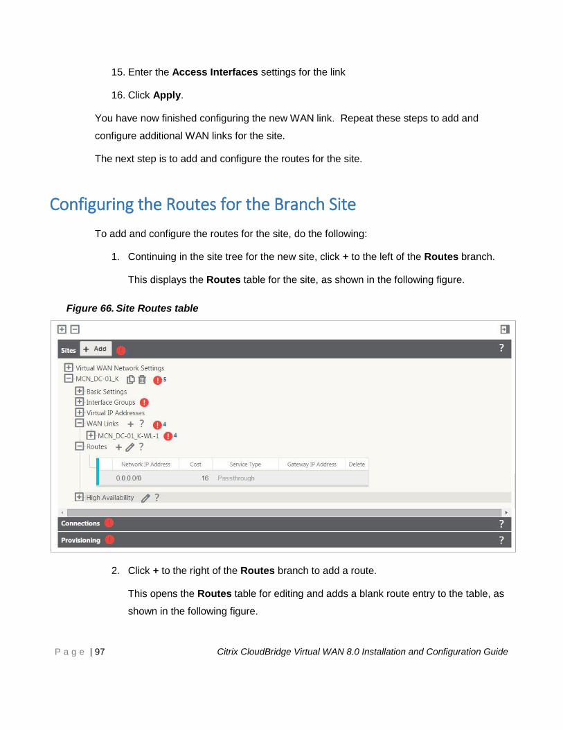
CloudBridge Virtual WAN 8.0
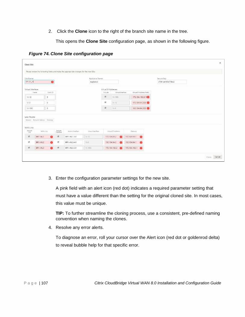
Installation and Configuration Guide
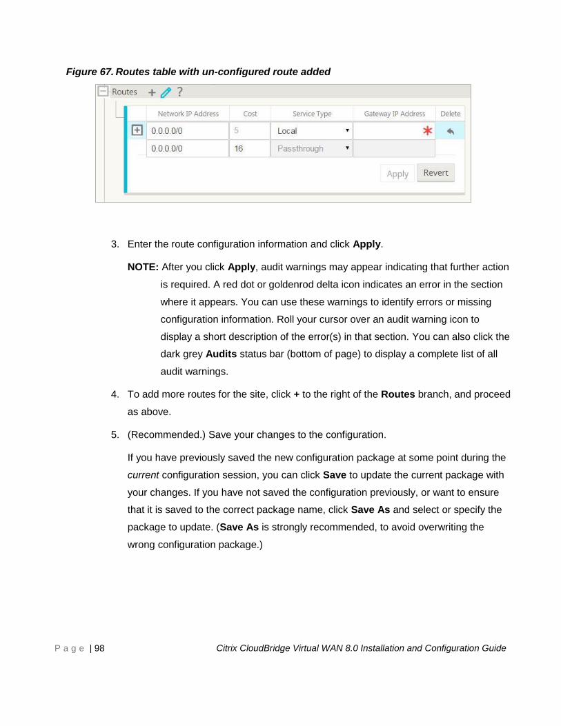
This document provides basic instructions for installing and configuring Citrix
CloudBridge Virtual WAN Appliances and sites in your CloudBridge Virtual WAN
network.
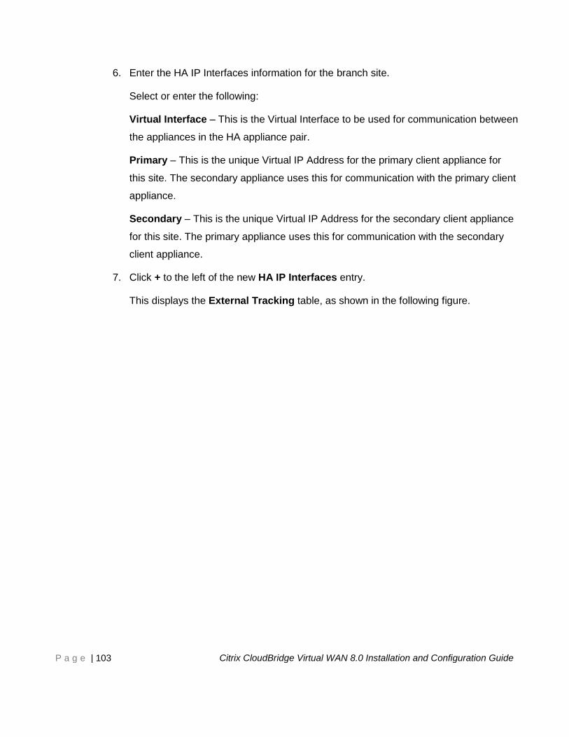
CITRIX SYSTEMS, INC | www.citrix.com
Page 2
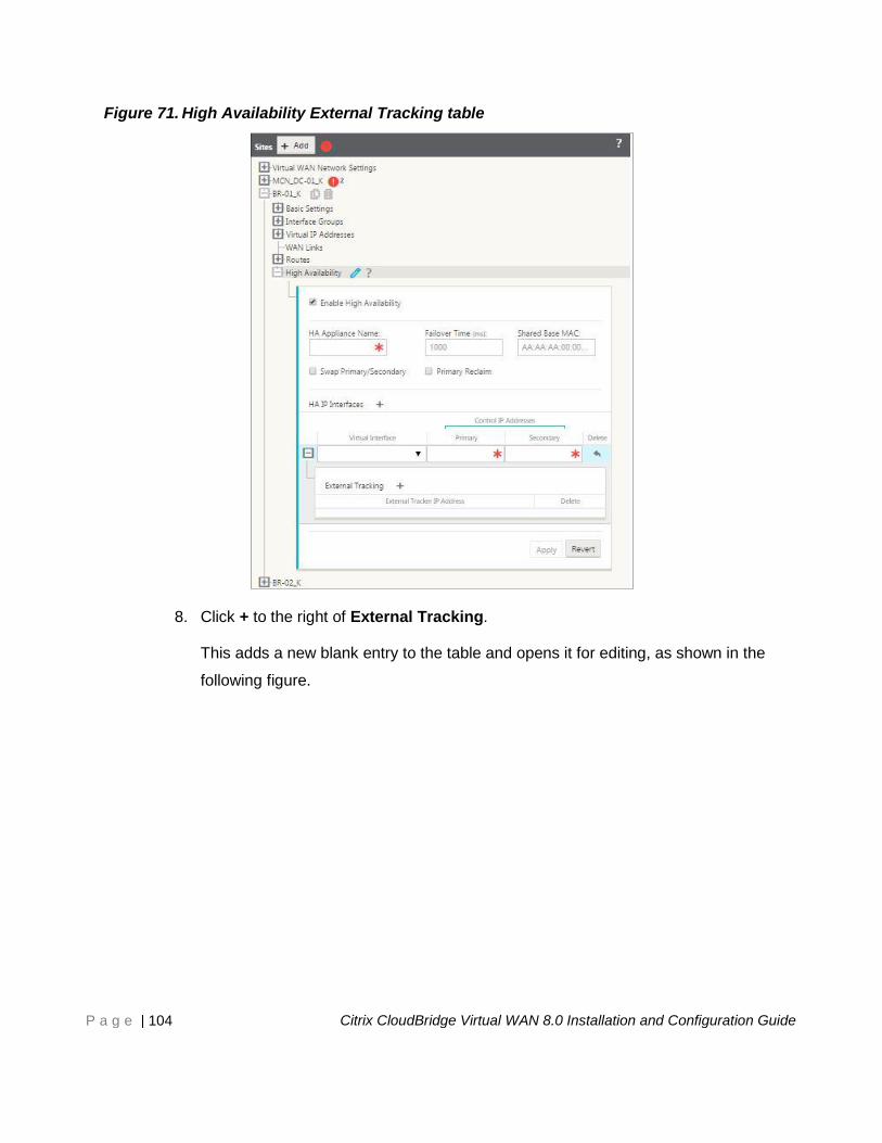
P a g e | 2 Citrix CloudBridge Virtual WAN 8.0 Installation and Configuration Guide
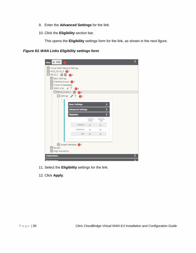
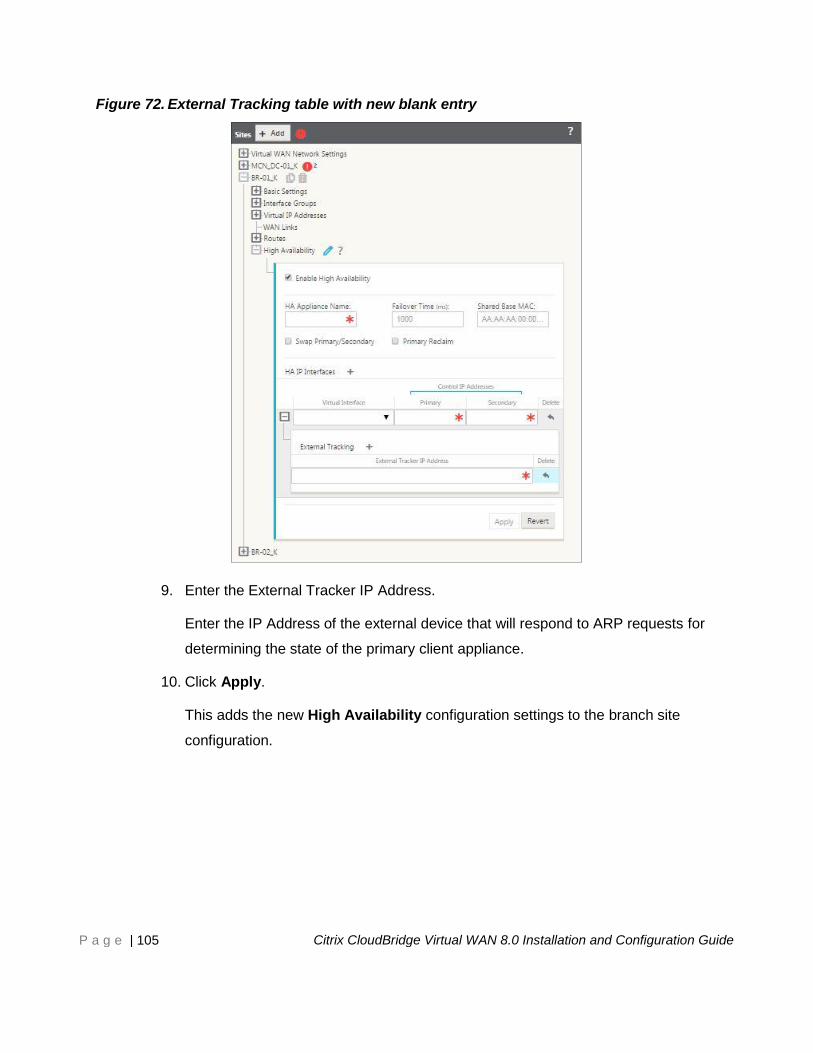
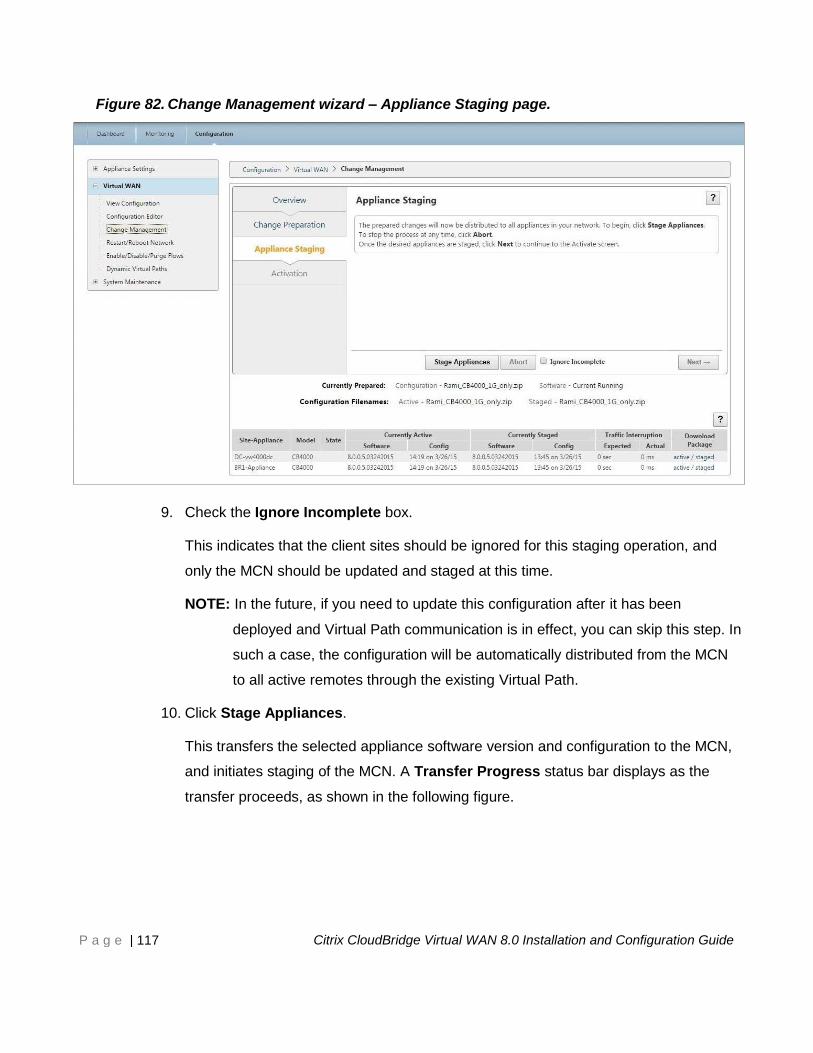
Copyright and Trademark Notice
© CITRIX SYSTEMS, INC., 2015. ALL RIGHTS RESERVED. NO PART OF THIS DOCUMENT MAY
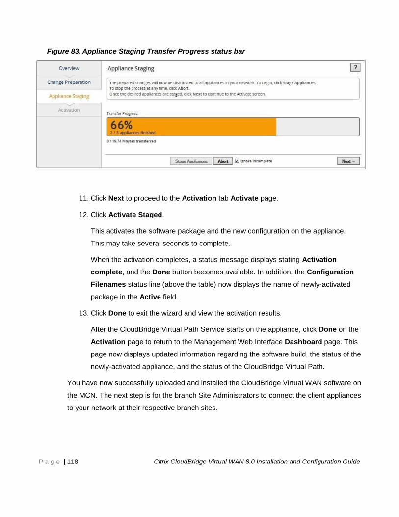
BE REPRODUCED OR TRANSMITTED IN ANY FORM OR BY ANY MEANS OR USED TO MAKE
DERIVATIVE WORK (SUCH AS TRANSLATION, TRANSFORMATION, OR ADAPTATION) WITHOUT
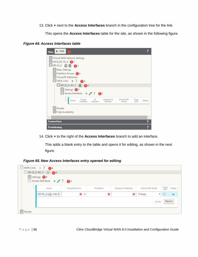
THE EXPRESS WRITTEN PERMISSION OF CITRIX SYSTEMS, INC.
Citrix, Citrix Systems, CloudBridge, Citrix Repeater, Branch Repeater, WANScaler, NetScaler,
XenServer, Orbital Data, Orbital 5500, Orbital 6500, Orbital 6800, TotalTransport, AutoOptimizer
Engine, and Adaptive Rate Control are trademarks of Citrix Systems.
Citrix Systems assumes no responsibility for errors in this document, and retains the right to make
changes at any time, without notice.
Portions licensed under the Apache License, Version 2.0 http://www.apache.org/ licenses/LICENSE-
2.0.
Portions licensed under the Gnu Public License, http://www.gnu.org/copyleft/gpl.html, including
xmlrpc++, glibc, rpmlibs, beecrypt.
Portions licensed under the Gnu Public License with product-specific clauses, including the Linux
kernel (http://www.kernel.org/pub/linux/kernel/COPYING), libstdc++, and libgcc.
Portions are free software with vendor-specific licensing, including zlib (http://
www.gzip.org/zlib/zlib_license.html), netsnmp (http://www.net-snmp.org/about/ license.html), openssl
(http://www.openssl.org/source/license.html), krb5-libs (http:/ /web.mit.edu/kerberos/krb5-1.3/krb5-
1.3.6/doc/krb5-install.html), tcp_wrappers (ftp://ftp.porcupine.org/pub/security/tcp_wrappers_license),
bzip2-libs (http:// sources.redhat.com/bzip2/), popt (http://directory.fsf.org/libs/COPYING.DOC). Elfutils-
libelf is licensed under the OSL 1.0 license, http://www.opensource.org.
JPGraph licensed under the terms given in http://www.aditus.nu/jpgraph/proversion.php.
LZS licensed from Hifn corporation, http://www.hifn.com.
Iperf licensed under the terms given in http://dast.nlanr.net/Projects/Iperf/ui_license.html.
This product includes PHP, freely available from http://www.php.net/.
Page 3
P a g e | 3 Citrix CloudBridge Virtual WAN 8.0 Installation and Configuration Guide
Contents 1 About This Guide .................................................................................................... 6
Purpose .......................................................................................................................... 6
Audience ........................................................................................................................ 6
How This Guide Is Organized ....................................................................................... 7
Document Font Conventions ....................................................................................... 9
Related Documents ....................................................................................................... 9
2 Overview ................................................................................................................ 10
The CloudBridge Virtual WAN 8.0 Software Packages ............................................. 10
Supported CloudBridge Virtual WAN Appliance Models .......................................... 11
The Master Control Node (MCN) ................................................................................ 12
The CloudBridge Virtual WAN Configuration ............................................................ 12
The CloudBridge Virtual WAN Appliance Packages ................................................. 13
CloudBridge Virtual WAN Security and Encryption Implementation ....................... 13
The CloudBridge Virtual WAN Management Web Interface ..................................... 14
Basic Navigation ................................................................................................... 14
Management Web Interface Page Hierarchy ............................................................. 16
The Management Web Interface Dashboard ........................................................ 18
The Configuration Editor ............................................................................................ 20
The Change Management Wizard .............................................................................. 23
3 Before You Begin .................................................................................................. 26
Hardware Installation Requirements.......................................................................... 26
Software Requirements .............................................................................................. 26
Browser Requirements ......................................................................................... 26
CloudBridge Virtual WAN Software Requirements ............................................. 27
Summary of Installation and Deployment Procedures ............................................. 28
4 Gathering Your CloudBridge Virtual WAN Deployment Information ................ 30
Installation and Deployment Information Checklist .................................................. 30
5 Setting up the CloudBridge Virtual WAN Appliances ........................................ 31
Setting up the Hardware ............................................................................................. 31
CB 1000 Management Port ................................................................................... 32
Page 4
P a g e | 4 Citrix CloudBridge Virtual WAN 8.0 Installation and Configuration Guide
CB 2000 Management Port ................................................................................... 33
CB 4000 Management Port ................................................................................... 33
Setting the Management IP Addresses for the Appliances ...................................... 34
6 Setting up the Master Control Node (MCN) Site ................................................. 40
Promote the Head End Appliance to the Role of MCN ............................................. 41
Adding the MCN Site ................................................................................................... 43
Configuring the Virtual Interface Groups for the MCN Site ...................................... 48
Configuring the Virtual IP Addresses for the MCN Site ............................................ 57
Configuring the WAN Links for the MCN Site ........................................................... 59
Configuring the Routes for the MCN Site .................................................................. 67
Configuring High Availability for the MCN Site (Optional) ....................................... 69
Enabling and Configuring Virtual WAN Security and Encryption (Optional) .......... 75
Naming and Saving the MCN Site Configuration ...................................................... 77
7 Adding and Configuring the Branch Sites .......................................................... 78
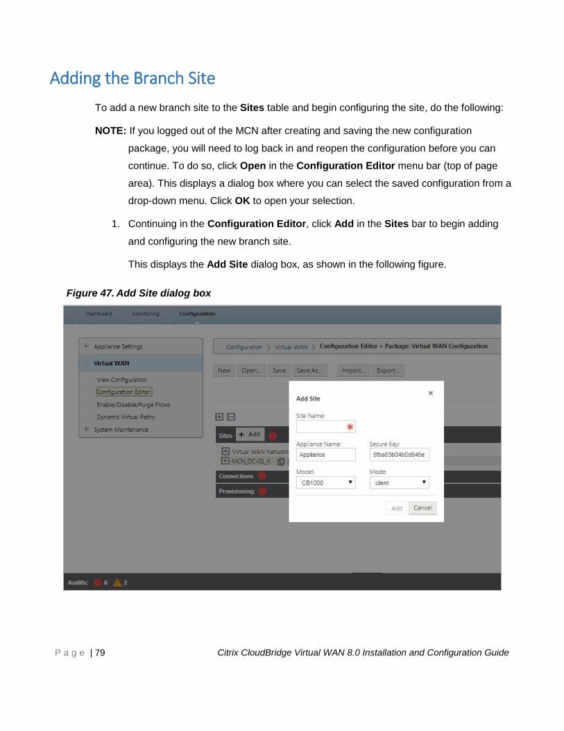
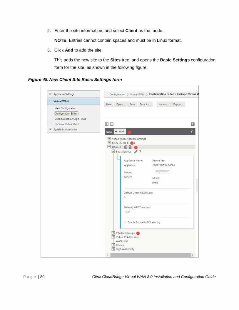
Adding the Branch Site ............................................................................................... 79
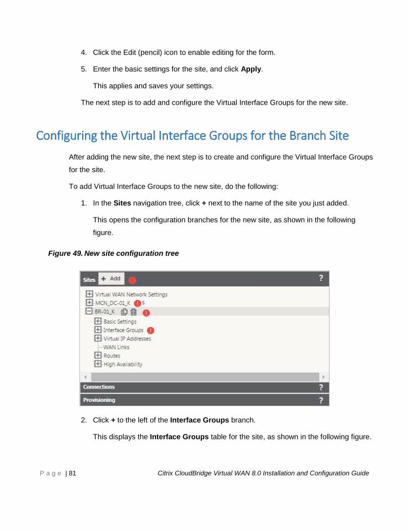
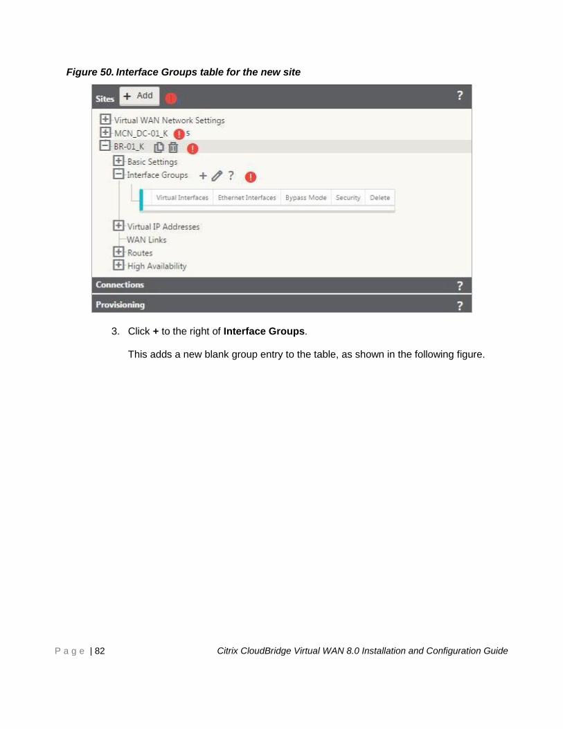
Configuring the Virtual Interface Groups for the Branch Site .................................. 81
Configuring the Virtual IP Addresses for the Branch Site ........................................ 89
Configuring the WAN Links for the Branch Site ....................................................... 91
Configuring the Routes for the Branch Site .............................................................. 97
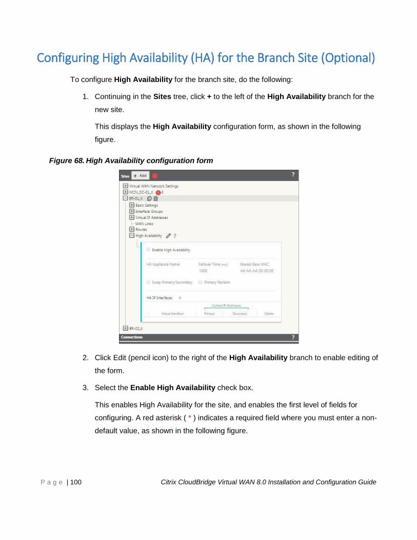
Configuring High Availability (HA) for the Branch Site (Optional) ......................... 100
Cloning the Branch Site (Optional) .......................................................................... 106
Resolving Configuration Error Alerts ...................................................................... 109
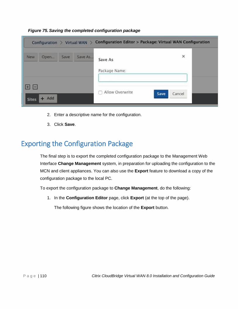
Saving the Completed Configuration ....................................................................... 109
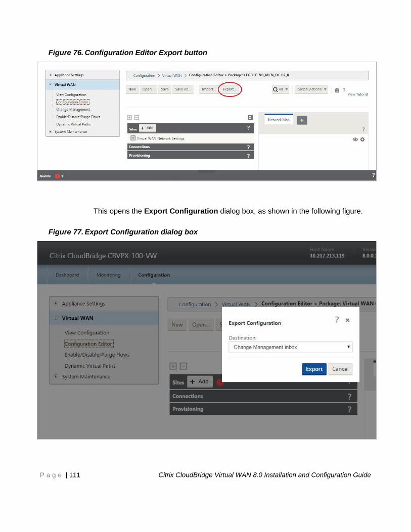
Exporting the Configuration Package ...................................................................... 110
8 Preparing the Virtual WAN Appliance Packages on the MCN ......................... 113
9 Connecting the Client Appliances to Your Network ........................................ 119
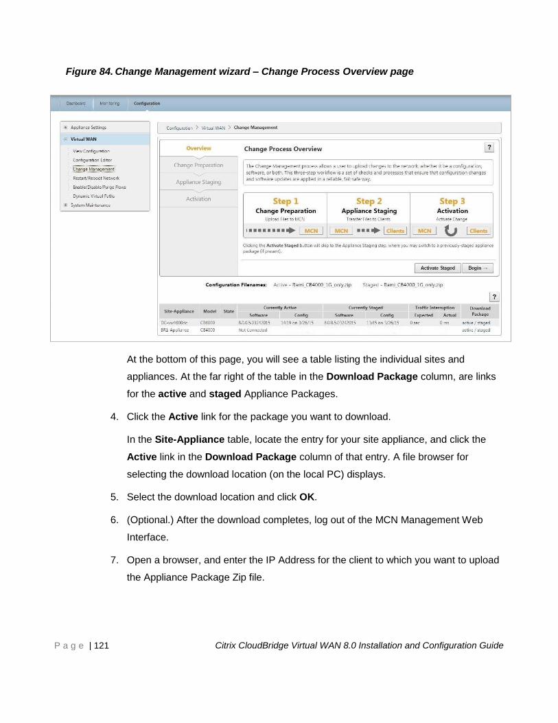
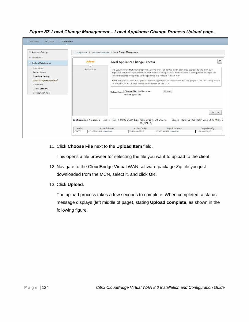
10 Installing the Virtual WAN Appliance Packages on the Clients ...................... 120
11 Monitoring Your CloudBridge Virtual WAN ...................................................... 128
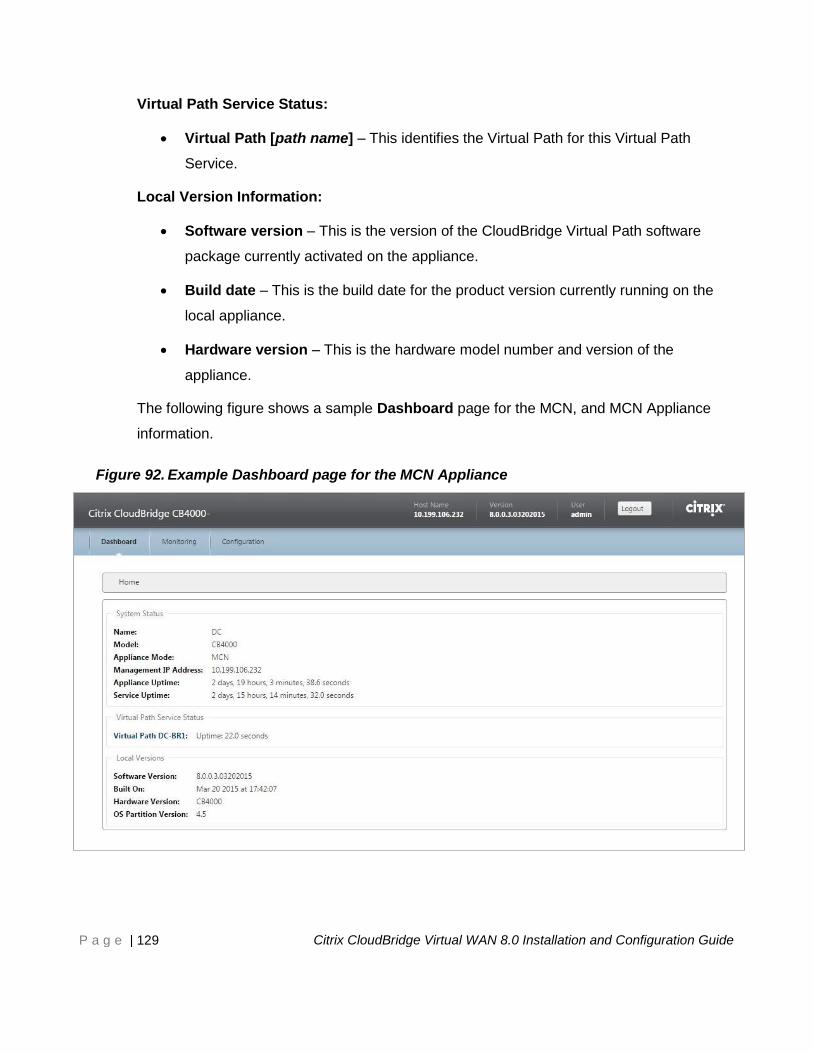
Viewing Basic Information for an Appliance ........................................................... 128
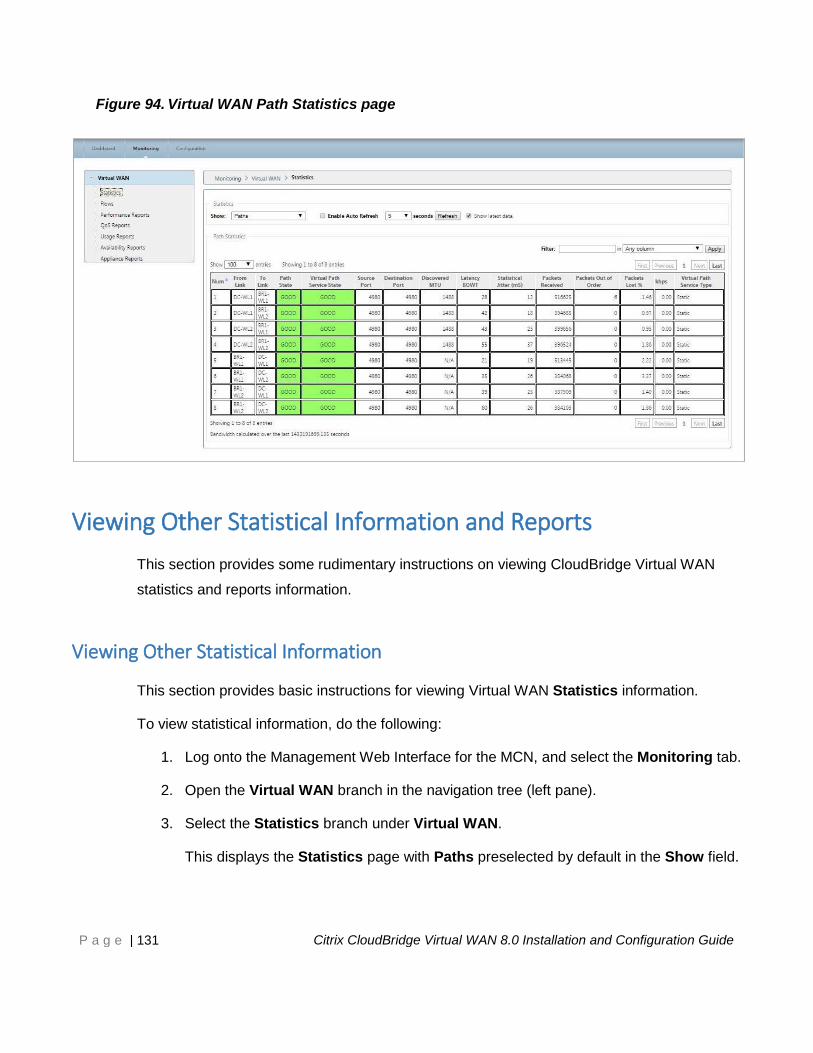
Viewing Path Statistics ............................................................................................. 130
Viewing Other Statistical Information and Reports ................................................ 131
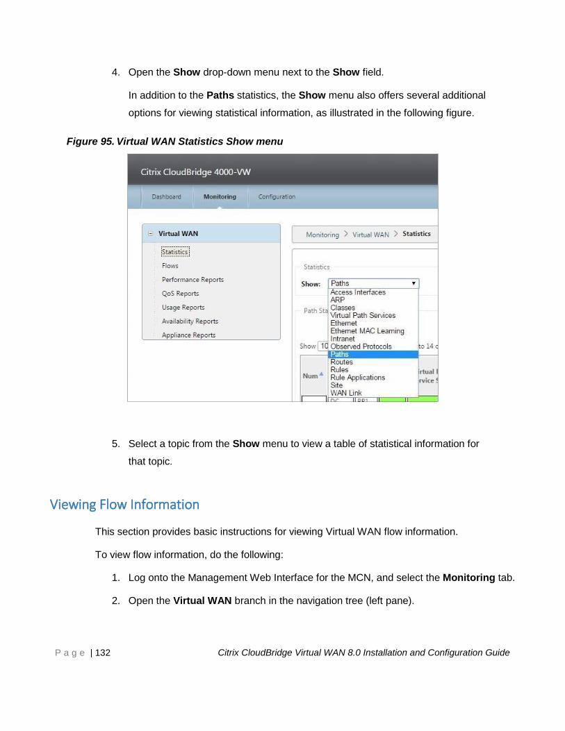
Viewing Other Statistical Information ................................................................ 131
Page 5
P a g e | 5 Citrix CloudBridge Virtual WAN 8.0 Installation and Configuration Guide
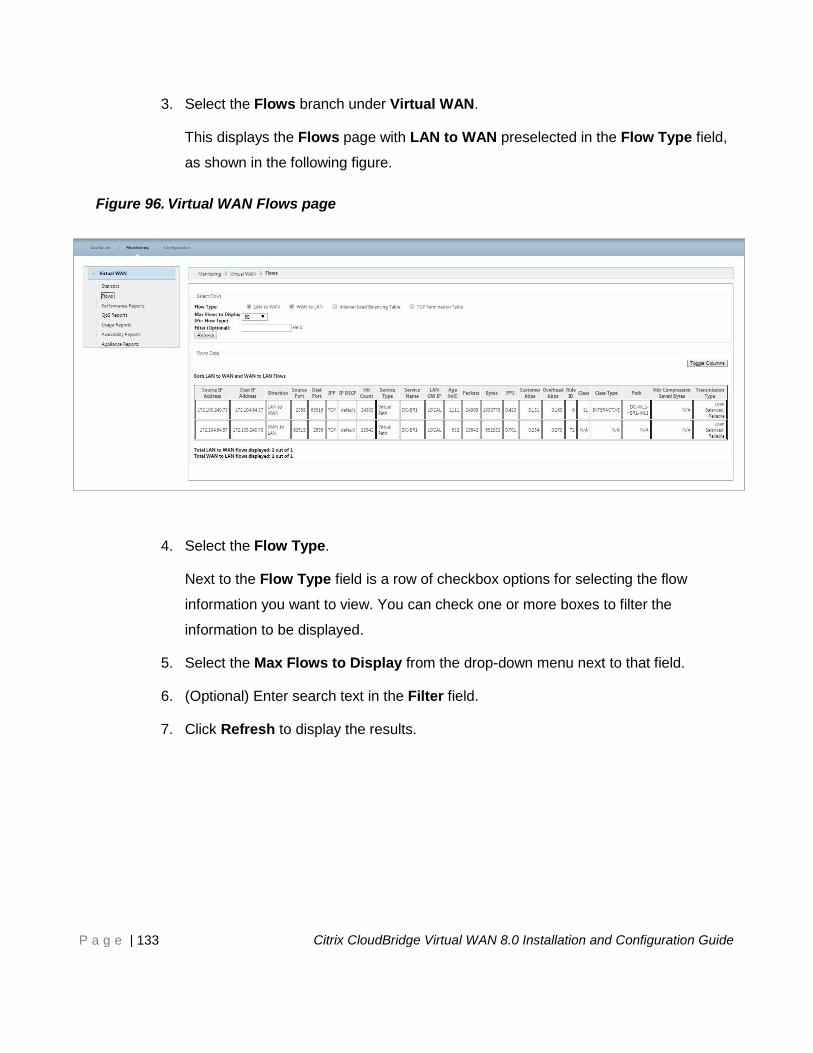
Viewing Flow Information ................................................................................... 132
Viewing Reports .................................................................................................. 134
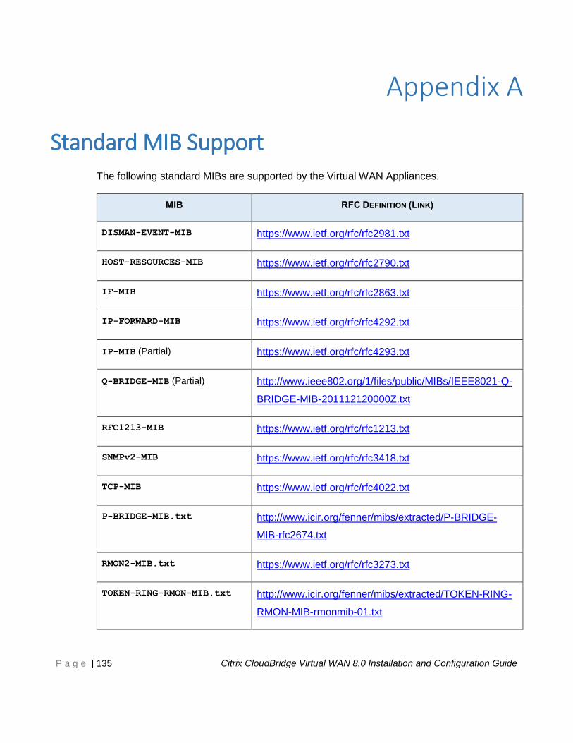
12 Standard MIB Support ........................................................................................ 135
Additional Notes ........................................................................................................ 136
13 Glossary ............................................................................................................... 137
Page 6
P a g e | 6 Citrix CloudBridge Virtual WAN 8.0 Installation and Configuration Guide
About This Guide This chapter provides an overview of the purpose and content of this guide. Topics include:
Purpose
Audience
How This Guide Is Organized
Document Font Conventions
Related Documents
The following sections provide details on each of these topics.
Purpose
This guide provides basic instructions for installing and deploying CloudBridge Virtual WAN
Appliances and the CloudBridge Virtual WAN software.
Audience
This guide is intended for Network Administrators and Architects. Readers are assumed to be
familiar with the physical setup and operation of networking equipment, and general
networking concepts.
Page 7
P a g e | 7 Citrix CloudBridge Virtual WAN 8.0 Installation and Configuration Guide
How This Guide Is Organized
A list and summary of each of the chapters in this guide are provided below.
Chapter 1: About This Guide – This chapter provides an overview of the purpose,
audience, and content of this guide. Also provided are a description of the font conventions
used in this guide, and a list of recommended and related documents.
Chapter 2: Overview – This chapter provides some basic information about the
CloudBridge Virtual WAN software packages and supported Virtual WAN Appliances. Also
included is a description and navigation roadmap of the CloudBridge Virtual WAN
Management Web Interface.
Chapter 3: Before You Begin – This chapter outlines the hardware and software
requirements for deploying Citrix CloudBridge Virtual WAN, and defines any platform
dependencies. Also provided is a summary and overview of the CloudBridge Virtual WAN
installation and deployment procedures described in this guide.
Chapter 4: Gathering Your CloudBridge Virtual WAN Deployment Information – This
chapter provides a checklist of the information you will need to complete the deployment.
Chapter 5: Setting up the CloudBridge Virtual WAN Appliances – This chapter describes
the procedures for setting up the CloudBridge Virtual WAN appliance hardware, and
configuring the Appliance Management IP Address.
Chapter 6: Setting up the Master Control Node (MCN) Site – This chapter provides
instructions for using the Configuration Editor to create and configure the MCN site. Also
included are instructions for enabling and configuring High Availability (HA) and Virtual WAN
security and encryption.
Chapter 7: Setting up the Branch Sites – This chapter provides instructions for creating
and configuring the branch sites.
Chapter 8: Installing the CloudBridge Virtual WAN Software on the MCN Appliance –
This provides instructions for uploading the Virtual WAN software and configuration to the
MCN appliance.
Page 8
P a g e | 8 Citrix CloudBridge Virtual WAN 8.0 Installation and Configuration Guide
Chapter 9: Connecting the Client Appliances to Your Network – This chapter provides
instructions for connecting the client appliances to your Virtual WAN network, in preparation
for installing the Virtual WAN Appliance packages on the clients.
Chapter 10: Installing the Virtual WAN Appliance Packages on the Clients – This
chapter provides instructions for installing, staging, and activating the CloudBridge Virtual
WAN Appliance packages on the Virtual WAN clients.
Chapter 11: Monitoring Your CloudBridge Virtual WAN – This chapter provides basic
instructions for generating and viewing statistics and reports to monitor the status of your
CloudBridge Virtual WAN deployment.
Appendix A: Standard MIB Support – This provides a table of the Standard MIBs
supported by CloudBridge Virtual WAN, which includes links to the RFC definitions for each
of these MIBs.
Glossary – This provides definitions of some of the fundamental CloudBridge Virtual WAN
terms and concepts.
Page 9
P a g e | 9 Citrix CloudBridge Virtual WAN 8.0 Installation and Configuration Guide
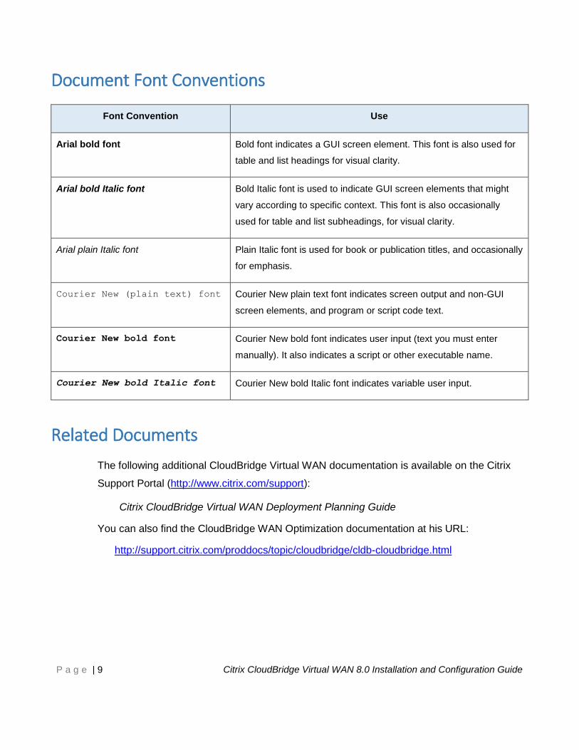
Document Font Conventions
Font Convention Use
Arial bold font Bold font indicates a GUI screen element. This font is also used for
table and list headings for visual clarity.
Arial bold Italic font Bold Italic font is used to indicate GUI screen elements that might
vary according to specific context. This font is also occasionally
used for table and list subheadings, for visual clarity.
Arial plain Italic font Plain Italic font is used for book or publication titles, and occasionally
for emphasis.
Courier New (plain text) font Courier New plain text font indicates screen output and non-GUI
screen elements, and program or script code text.
Courier New bold font Courier New bold font indicates user input (text you must enter
manually). It also indicates a script or other executable name.
Courier New bold Italic font Courier New bold Italic font indicates variable user input.
Related Documents
The following additional CloudBridge Virtual WAN documentation is available on the Citrix
Support Portal (http://www.citrix.com/support):
Citrix CloudBridge Virtual WAN Deployment Planning Guide
You can also find the CloudBridge WAN Optimization documentation at his URL:
http://support.citrix.com/proddocs/topic/cloudbridge/cldb-cloudbridge.html
Page 10
P a g e | 10 Citrix CloudBridge Virtual WAN 8.0 Installation and Configuration Guide
Overview This chapter provides some basic information about the CloudBridge Virtual WAN software
packages and supported Virtual WAN Appliances. Also included is a brief description of the
Virtual WAN Master Control Node (MCN), the Virtual WAN Configuration, and the Virtual
WAN Appliance packages. The chapter concludes with an overview and navigation roadmap
of the CloudBridge Virtual WAN Management Web Interface (MWI), and basic instructions for
using the MWI Configuration Editor and Change Management wizard.
The following sections provide the essential information for each of these topics.
The CloudBridge Virtual WAN 8.0 Software Packages
There is a different version of the Citrix CloudBridge Virtual WAN 8.0 software for each
supported CloudBridge Virtual WAN Appliance model. You will need to acquire the
appropriate version for each appliance model you plan to incorporate into your network.
The following section discusses the supported CloudBridge Virtual WAN Appliance models.
Page 11
P a g e | 11 Citrix CloudBridge Virtual WAN 8.0 Installation and Configuration Guide
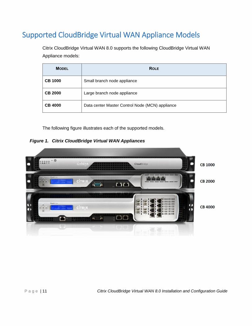
Supported CloudBridge Virtual WAN Appliance Models
Citrix CloudBridge Virtual WAN 8.0 supports the following CloudBridge Virtual WAN
Appliance models:
MODEL ROLE
CB 1000 Small branch node appliance
CB 2000 Large branch node appliance
CB 4000 Data center Master Control Node (MCN) appliance
The following figure illustrates each of the supported models.
Figure 1. Citrix CloudBridge Virtual WAN Appliances
Page 12
P a g e | 12 Citrix CloudBridge Virtual WAN 8.0 Installation and Configuration Guide
The Master Control Node (MCN)
The Master Control Node (MCN) is the central Virtual WAN Appliance that acts as the master
controller of the Virtual WAN, and the central administration point for the client nodes. All
configuration, software package distribution, and management activities for the Virtual WAN
are performed on or from the MCN.
The primary purpose of the MCN is to establish and utilize Virtual Paths with one or more
client nodes located across the Virtual WAN, for Enterprise Site-to-Site communications. An
MCN can administer and have Virtual Paths to multiple client nodes. There can be more than
one MCN, but only one can be active at any given time.
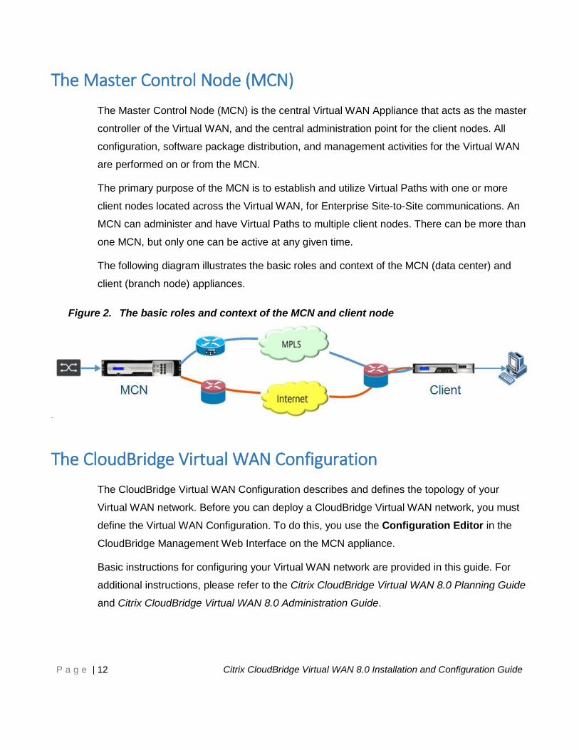
The following diagram illustrates the basic roles and context of the MCN (data center) and
client (branch node) appliances.
Figure 2. The basic roles and context of the MCN and client node
The CloudBridge Virtual WAN Configuration
The CloudBridge Virtual WAN Configuration describes and defines the topology of your
Virtual WAN network. Before you can deploy a CloudBridge Virtual WAN network, you must
define the Virtual WAN Configuration. To do this, you use the Configuration Editor in the
CloudBridge Management Web Interface on the MCN appliance.
Basic instructions for configuring your Virtual WAN network are provided in this guide. For
additional instructions, please refer to the Citrix CloudBridge Virtual WAN 8.0 Planning Guide
and Citrix CloudBridge Virtual WAN 8.0 Administration Guide.
Page 13
P a g e | 13 Citrix CloudBridge Virtual WAN 8.0 Installation and Configuration Guide
The CloudBridge Virtual WAN Appliance Packages
There is a different version of the Citrix CloudBridge Virtual WAN 8.0 software for each
supported CloudBridge Virtual WAN Appliance model. A Virtual WAN Appliance package is
a combined package containing the Virtual WAN software version for a particular appliance
model, bundled together with a specific Virtual WAN Configuration package. The two
components are bundled together and distributed to the clients by means of the Change
Management wizard in the Management Web Interface running on the Master Control Node
(MCN). You then must upload, stage, and activate the appropriate Appliance Package on
each of the client appliances residing in your Virtual WAN network.
CloudBridge Virtual WAN Security and Encryption
Implementation
The use of encryption in the CloudBridge Virtual WAN (for Virtual Paths) is an optional
feature for CloudBridge Virtual WAN. Instructions for configuring this feature are provided in
the section entitled, “Enabling and Configuring Virtual WAN Security and Encryption
(Optional),” in “Chapter 6: Setting up the Master Control Node (MCN) Site.”
The Advanced Encryption Standard (AES) is used by CloudBridge Virtual WAN to secure
traffic across the Virtual Path. Both AES 128 and 256 bit ciphers (key sizes) are supported by
the Virtual WAN Appliances, and are configurable options. You can select, enable, and
configure these and the other encryption options by using the Configuration Editor in
Management Web Interface on the Management Control Node (MCN). You must have
administrative access on the MCN to modify the configuration, and to distribute your changes
across the Virtual WAN. Once the MCN is secured, the encryption settings and their
distribution are also secure.
Authentication between sites functions by means of the Virtual WAN Configuration. The
network configuration has a secret for each site. For each Virtual Path, the network
configuration generates a key by combining the secrets from the sites at each end of the
Virtual Path. The initial key exchange that occurs when a Virtual Path is first set up, is
dependent upon the ability to encrypt and decrypt packets by means of that combined key.
Page 14
P a g e | 14 Citrix CloudBridge Virtual WAN 8.0 Installation and Configuration Guide
The CloudBridge Virtual WAN Management Web Interface
This section provides basic navigation instructions, and a navigation roadmap of the
Management Web Interface page hierarchy. Also provided are specific navigation instructions
for the Configuration Editor and Change Management wizard.
Basic Navigation
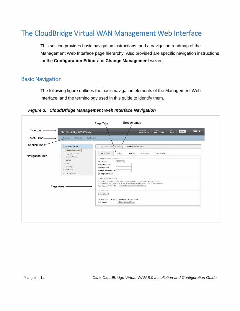
The following figure outlines the basic navigation elements of the Management Web
Interface, and the terminology used in this guide to identify them.
Figure 3. CloudBridge Management Web Interface Navigation
Page 15
P a g e | 15 Citrix CloudBridge Virtual WAN 8.0 Installation and Configuration Guide
The basic navigation elements are as follows:
Title bar – This is the dark grey bar at the top of all Management Web Interface
screens. This displays the appliance model number, Host IP Address for the
appliance, the software version currently running on the appliance, and the user name
for the current login session. The title bar also contains the Logout button for
terminating the session.
Main menu bar – This is the light blue bar displayed below the title bar on every
Management Web Interface screen. This contains the section tabs for displaying the
navigation tree and pages for a selected section.
Section tabs – The section tabs are located in the blue main menu bar at the top of
the page. These are the top-level categories for the Management Web Interface
pages and forms. Each section has its own navigation tree for navigating the page
hierarchy in that section. Click a section tab to display the navigation tree for that
section.
Navigation tree – The navigation tree is located in the left blue and grey pane, below
the main menu bar. This displays the navigation tree for a section. Click a section tab
to display the navigation tree for that section. The navigation tree offers the following
display and navigation options:
Click a section tab to display the navigation tree and page hierarchy for that
section.
Click + (plus sign) next to a branch in the tree to reveal the available pages for
that branch topic.
Click a page name to display that page in the page area.
Click – (minus sign) next to a branch item to close the branch.
Breadcrumbs – This displays the navigation path to the current page. The
breadcrumbs are located at the top of the page area, just below the main menu bar.
Active navigation links display in blue font. The name of the current page is displayed
in black bold font.
Page 16
P a g e | 16 Citrix CloudBridge Virtual WAN 8.0 Installation and Configuration Guide
Page area – This is the page display and work area for the selected page. Select an
item in the navigation tree to display the default page for that item.
Page tabs – Some pages contain tabs for displaying additional child pages for that
topic or configuration form. These are usually located at the top of the page area, just
below the breadcrumbs display. In some cases (as for the Change Management
wizard), tabs are located in the left pane of the page area, between the navigation
tree and the work area of the page.
Page area resizing – For some pages, you can grow or shrink the width of the page
area (or sections of it) to reveal additional fields in a table or form. These pages areas
contain a resize bar (not shown in the figure above) for this purpose. Where available,
the resize bar is the grey vertical bar located on the right border of a page area pane,
form, or table. Roll your cursor over the resize bar until the cursor changes to a bi-
directional arrow. Then click and drag the bar to the right or left to grow or shrink the
area width.
If the resize bar is not available for a page, you can click and drag the right edge of
your browser to display the full page.
Management Web Interface Page Hierarchy
The Management Web Interface pages and forms are organized into three top-level sections,
as follows:
Dashboard
Monitoring
Configuration
Click a section tab in the main menu bar to display the navigation tree for that section. Then
select an item in the navigation tree to display the default page for that item.
The following table provides a navigation roadmap of the Management Web Interface
navigation tree hierarchy.
Page 17
P a g e | 17 Citrix CloudBridge Virtual WAN 8.0 Installation and Configuration Guide
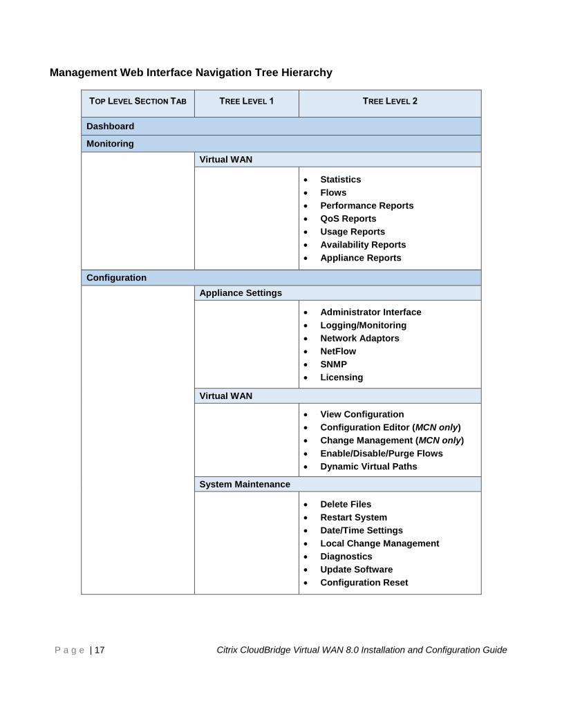
Management Web Interface Navigation Tree Hierarchy
TOP LEVEL SECTION TAB TREE LEVEL 1 TREE LEVEL 2
Dashboard
Monitoring
Virtual WAN
Statistics
Flows
Performance Reports
QoS Reports
Usage Reports
Availability Reports
Appliance Reports
Configuration
Appliance Settings
Administrator Interface
Logging/Monitoring
Network Adaptors
NetFlow
SNMP
Licensing
Virtual WAN
View Configuration
Configuration Editor (MCN only)
Change Management (MCN only)
Enable/Disable/Purge Flows
Dynamic Virtual Paths
System Maintenance
Delete Files
Restart System
Date/Time Settings
Local Change Management
Diagnostics
Update Software
Configuration Reset
Page 18
P a g e | 18 Citrix CloudBridge Virtual WAN 8.0 Installation and Configuration Guide
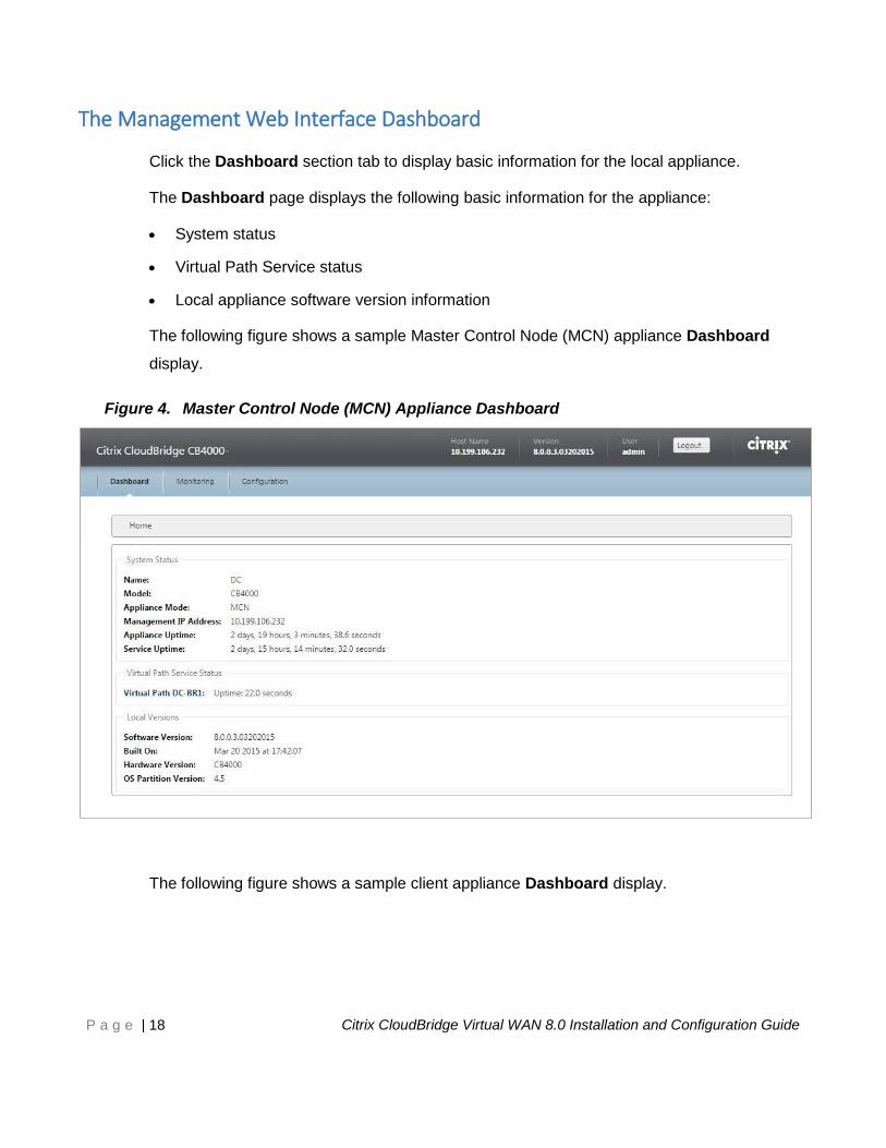
The Management Web Interface Dashboard
Click the Dashboard section tab to display basic information for the local appliance.
The Dashboard page displays the following basic information for the appliance:
System status
Virtual Path Service status
Local appliance software version information
The following figure shows a sample Master Control Node (MCN) appliance Dashboard
display.
Figure 4. Master Control Node (MCN) Appliance Dashboard
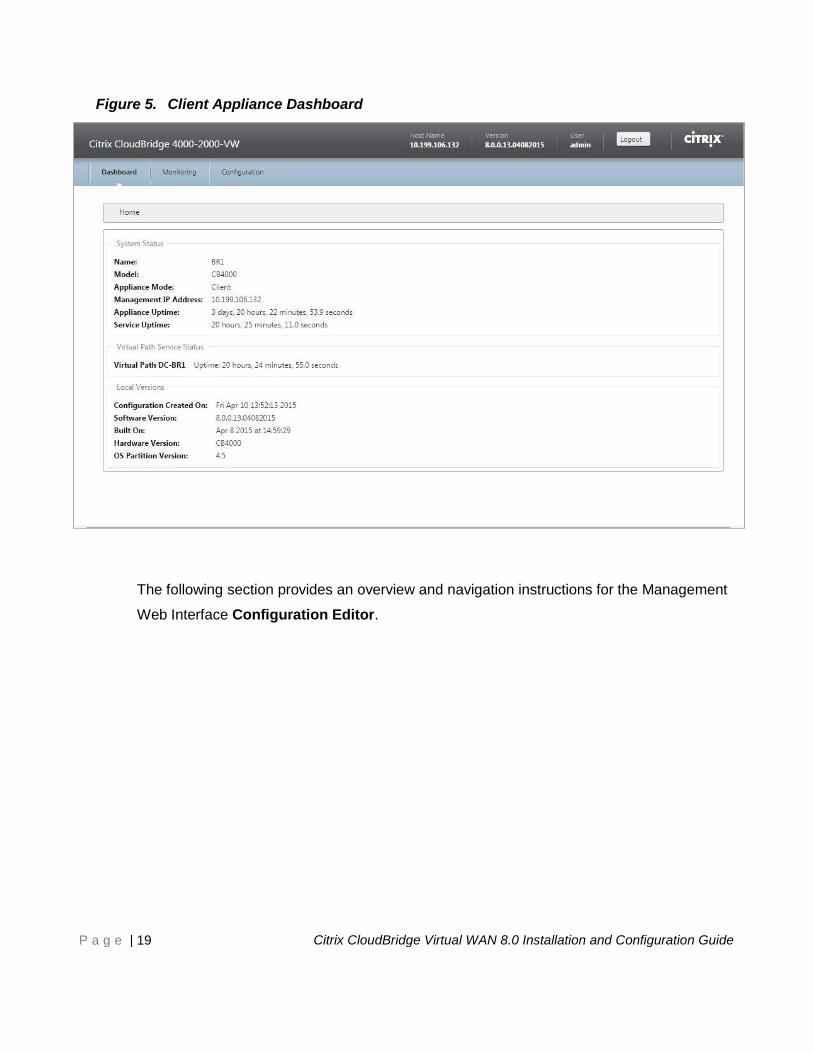
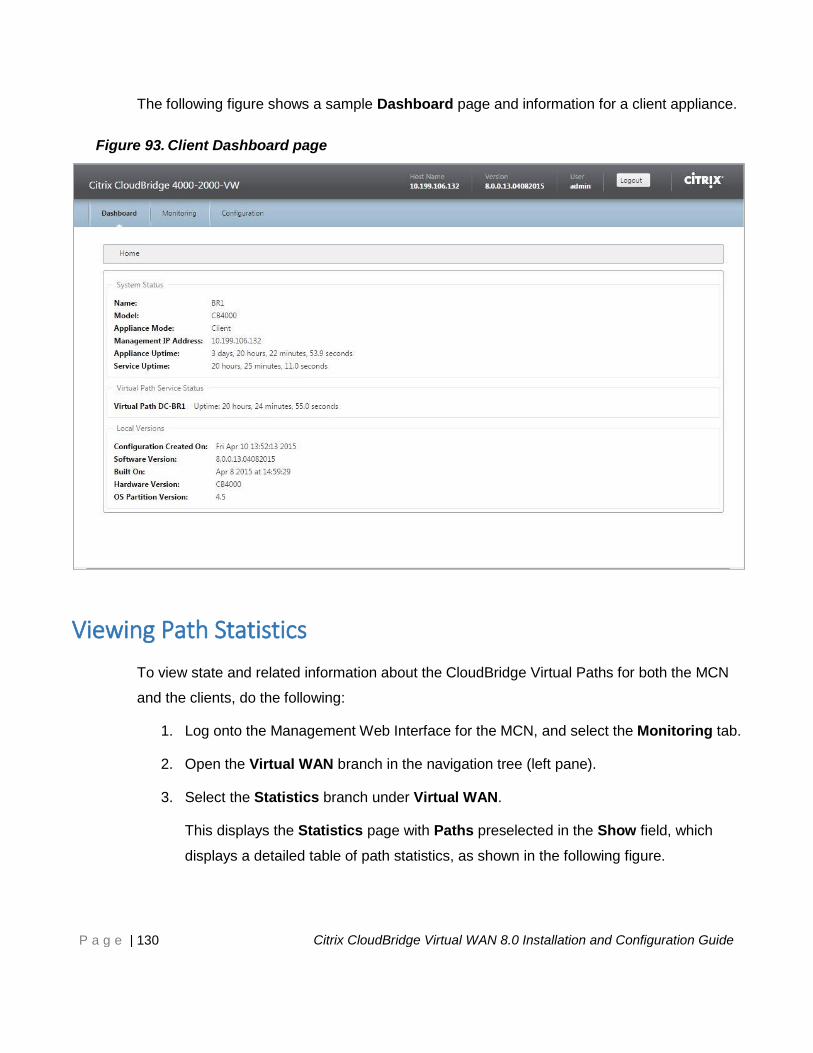
The following figure shows a sample client appliance Dashboard display.
Page 19
P a g e | 19 Citrix CloudBridge Virtual WAN 8.0 Installation and Configuration Guide
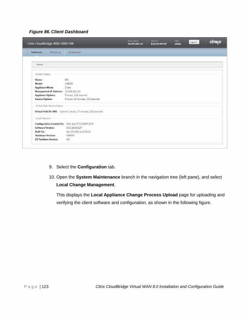
Figure 5. Client Appliance Dashboard
The following section provides an overview and navigation instructions for the Management
Web Interface Configuration Editor.
Page 20
P a g e | 20 Citrix CloudBridge Virtual WAN 8.0 Installation and Configuration Guide
The Configuration Editor
The Configuration Editor enables you to add and configure CloudBridge Virtual WAN
Appliance sites, connections, and provisioning, and to create and define the Virtual WAN
Configuration.
The Configuration Editor is available when the Management Web Interface is in MCN
Console mode, only. For information on switching the interface to MCN Console mode,
see the section entitled, “Specifying the MCN” in “Chapter 6: Setting up the Master Control
Node (MCN).”
To navigate to the Configuration Editor, do the following:
1. Log into the Management Web Interface on the MCN appliance.
2. Select the Configuration tab.
3. In the navigation tree, click + next to the Virtual WAN branch in the tree.
This displays the available pages for the Virtual WAN category.
4. In the Virtual WAN branch of the tree, select Configuration Editor.
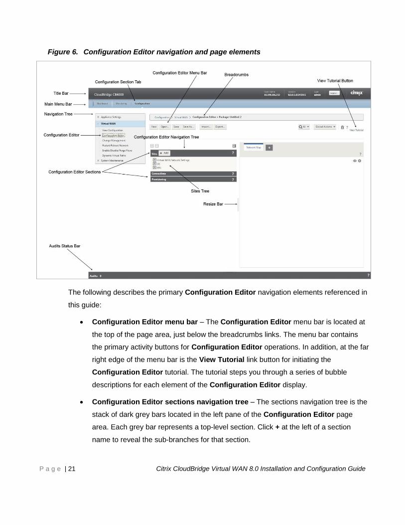
The following figure outlines the basic navigation and page elements of the Configuration
Editor, and the terminology used in this guide to identify them.
Page 21
P a g e | 21 Citrix CloudBridge Virtual WAN 8.0 Installation and Configuration Guide
Figure 6. Configuration Editor navigation and page elements
The following describes the primary Configuration Editor navigation elements referenced in
this guide:
Configuration Editor menu bar – The Configuration Editor menu bar is located at
the top of the page area, just below the breadcrumbs links. The menu bar contains
the primary activity buttons for Configuration Editor operations. In addition, at the far
right edge of the menu bar is the View Tutorial link button for initiating the
Configuration Editor tutorial. The tutorial steps you through a series of bubble
descriptions for each element of the Configuration Editor display.
Configuration Editor sections navigation tree – The sections navigation tree is the
stack of dark grey bars located in the left pane of the Configuration Editor page
area. Each grey bar represents a top-level section. Click + at the left of a section
name to reveal the sub-branches for that section.
Page 22
P a g e | 22 Citrix CloudBridge Virtual WAN 8.0 Installation and Configuration Guide
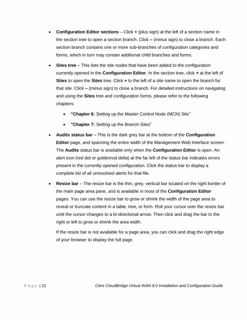
Configuration Editor sections – Click + (plus sign) at the left of a section name in
the section tree to open a section branch. Click – (minus sign) to close a branch. Each
section branch contains one or more sub-branches of configuration categories and
forms, which in turn may contain additional child branches and forms.
Sites tree – This lists the site nodes that have been added to the configuration
currently opened in the Configuration Editor. In the section tree, click + at the left of
Sites to open the Sites tree. Click + to the left of a site name to open the branch for
that site. Click – (minus sign) to close a branch. For detailed instructions on navigating
and using the Sites tree and configuration forms, please refer to the following
chapters:
“Chapter 6: Setting up the Master Control Node (MCN) Site”
“Chapter 7: Setting up the Branch Sites”
Audits status bar – This is the dark grey bar at the bottom of the Configuration
Editor page, and spanning the entire width of the Management Web Interface screen.
The Audits status bar is available only when the Configuration Editor is open. An
alert icon (red dot or goldenrod delta) at the far left of the status bar indicates errors
present in the currently-opened configuration. Click the status bar to display a
complete list of all unresolved alerts for that file.
Resize bar – The resize bar is the thin, grey, vertical bar located on the right border of
the main page area pane, and is available in most of the Configuration Editor
pages. You can use the resize bar to grow or shrink the width of the page area to
reveal or truncate content in a table, tree, or form. Roll your cursor over the resize bar
until the cursor changes to a bi-directional arrow. Then click and drag the bar to the
right or left to grow or shrink the area width.
If the resize bar is not available for a page area, you can click and drag the right edge
of your browser to display the full page.
Page 23
P a g e | 23 Citrix CloudBridge Virtual WAN 8.0 Installation and Configuration Guide
The Change Management Wizard
The Change Management wizard guides you through the process of uploading,
downloading, staging, and activating the CloudBridge Virtual WAN software and configuration
on the Master Control Node (MCN) appliance and client appliances.
To open the Change Management Wizard, do the following:
1. Log into the Management Web Interface on the MCN appliance.
2. Select the Configuration tab.
3. In the navigation tree, click + next to the Virtual WAN branch in the tree.
4. In the Virtual WAN branch, select Change Management.
This displays the first page of the Change Management wizard, the Change
Process Overview page, as shown in the following figure.
Figure 7. First page of the Change Management wizard
Page 24
P a g e | 24 Citrix CloudBridge Virtual WAN 8.0 Installation and Configuration Guide
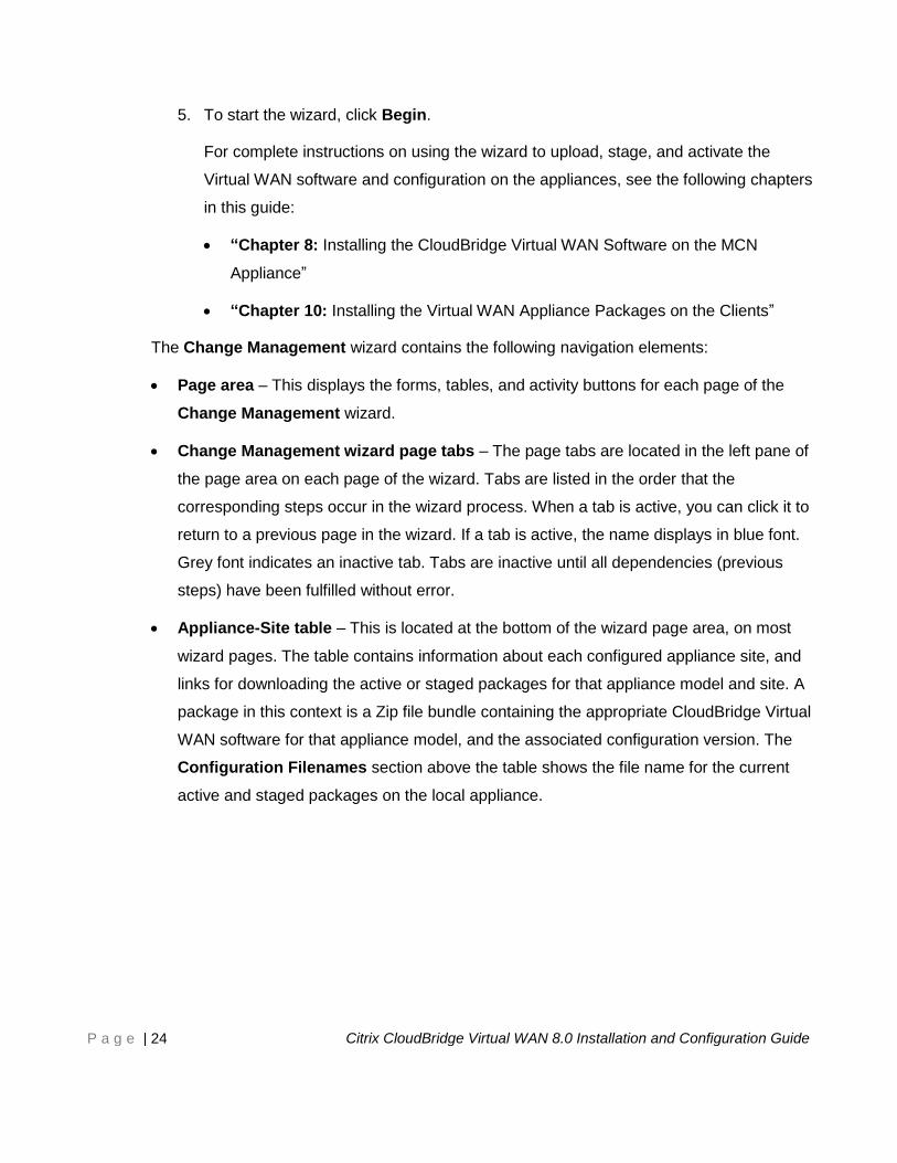
5. To start the wizard, click Begin.
For complete instructions on using the wizard to upload, stage, and activate the
Virtual WAN software and configuration on the appliances, see the following chapters
in this guide:
“Chapter 8: Installing the CloudBridge Virtual WAN Software on the MCN
Appliance”
“Chapter 10: Installing the Virtual WAN Appliance Packages on the Clients”
The Change Management wizard contains the following navigation elements:
Page area – This displays the forms, tables, and activity buttons for each page of the
Change Management wizard.
Change Management wizard page tabs – The page tabs are located in the left pane of
the page area on each page of the wizard. Tabs are listed in the order that the
corresponding steps occur in the wizard process. When a tab is active, you can click it to
return to a previous page in the wizard. If a tab is active, the name displays in blue font.
Grey font indicates an inactive tab. Tabs are inactive until all dependencies (previous
steps) have been fulfilled without error.
Appliance-Site table – This is located at the bottom of the wizard page area, on most
wizard pages. The table contains information about each configured appliance site, and
links for downloading the active or staged packages for that appliance model and site. A
package in this context is a Zip file bundle containing the appropriate CloudBridge Virtual
WAN software for that appliance model, and the associated configuration version. The
Configuration Filenames section above the table shows the file name for the current
active and staged packages on the local appliance.
Page 25
P a g e | 25 Citrix CloudBridge Virtual WAN 8.0 Installation and Configuration Guide
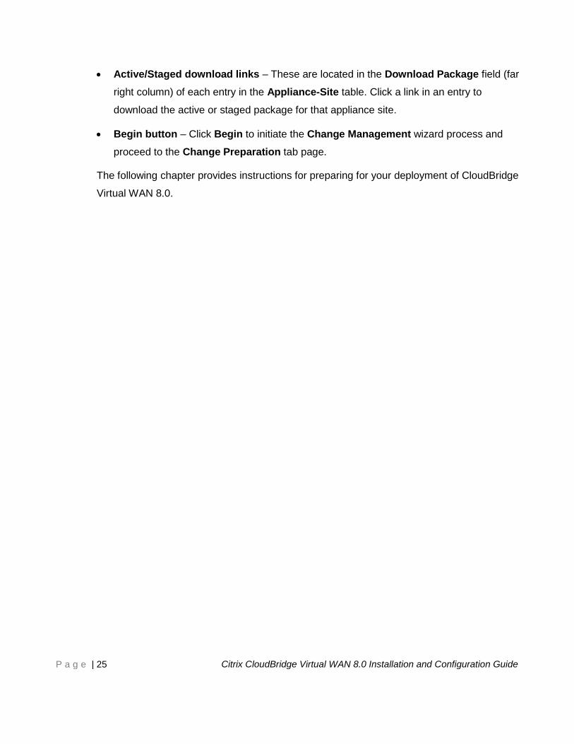
Active/Staged download links – These are located in the Download Package field (far
right column) of each entry in the Appliance-Site table. Click a link in an entry to
download the active or staged package for that appliance site.
Begin button – Click Begin to initiate the Change Management wizard process and
proceed to the Change Preparation tab page.
The following chapter provides instructions for preparing for your deployment of CloudBridge
Virtual WAN 8.0.
Page 26
P a g e | 26 Citrix CloudBridge Virtual WAN 8.0 Installation and Configuration Guide
Before You Begin This chapter outlines the hardware and software requirements for deploying Citrix
CloudBridge Virtual WAN, and defines any platform dependencies. Also provided is a
summary and overview of the CloudBridge Virtual WAN installation and deployment
procedures described in this guide.
Hardware Installation Requirements
Instructions for installing your CloudBridge Virtual WAN Appliances are provided in
“Chapter 5: Setting up the CloudBridge Virtual WAN Appliances,” in this guide.
Related information on CloudBridge WAN Optimization can be found at this location:
http://support.citrix.com/proddocs/topic/cloudbridge/cldb-cloudbridge.html
Software Requirements
This section outlines the software requirements for deploying and operating the CloudBridge
Virtual WAN. Also provided is basic information on acquiring and downloading the
CloudBridge Virtual WAN software packages.
Browser Requirements
Supported browsers must have cookies enabled, and JavaScript installed and enabled.
Page 27
P a g e | 27 Citrix CloudBridge Virtual WAN 8.0 Installation and Configuration Guide
The CloudBridge Virtual WAN Management Web Interface supports the following browsers
and versions:
Microsoft Internet Explorer 10+
Mozilla Firefox 35.0+
Google Chrome 40.0+
CloudBridge Virtual WAN Software Requirements
This section provides basic information on acquiring and downloading the CloudBridge Virtual
WAN software.
There is a different version of the software for each CloudBridge Virtual WAN appliance
model. You will need to download the appropriate package for each appliance model type
you want to add to your network.
CloudBridge Virtual WAN supports these appliance models:
CB 1000
CB 2000
CB 4000
Before you can download the software, you must acquire and register a CloudBridge Virtual
WAN software license, as follows:
To acquire a license: For instructions on acquiring a CloudBridge Virtual WAN software
license, please contact Citrix CloudBridge Sales or Customer Support.
To download the software packages: To download the CloudBridge Virtual WAN
software packages, go to the following URL:
http://www.citrix.com/downloads.html
Instructions for downloading the software are provided on this site.
The following section provides a summary of the steps and procedures involved in deploying
CloudBridge Virtual WAN.
Page 28
P a g e | 28 Citrix CloudBridge Virtual WAN 8.0 Installation and Configuration Guide
Summary of Installation and Deployment Procedures
The following list outlines the steps and procedures involved in deploying CloudBridge
Virtual WAN.
1. Gather your CloudBridge Virtual WAN deployment information.
2. Set up the CloudBridge Virtual WAN Appliances.
a) Set up the hardware.
b) Set the Management IP Addresses for the appliances.
3. Set up the Master Control Node (MCN) site.
a) Promote the head end appliance to the role of Master Control Node (MCN).
b) Add and configure the MCN site.
c) Configure the Virtual Interface Groups for the MCN site.
d) Configure the Virtual IP Addresses for the MCN site.
e) Configure the WAN Links for the MCN site.
f) Configure the Routes for the MCN site.
g) (Optional) Configure High Availability (HA) for the MCN site.
h) (Optional) Configure Virtual WAN security and encryption.
i) Save the MCN site configuration.
4. Set up the branch sites.
a) Add the branch site.
b) Configure the Virtual Interface Groups for the branch site.
c) Configure the Virtual IP Addresses for the branch site.
d) Configure the WAN Links for the branch site.
e) Configure the Routes for the branch site.
f) (Optional) Configure High Availability (HA) for the branch site.
Page 29
P a g e | 29 Citrix CloudBridge Virtual WAN 8.0 Installation and Configuration Guide
g) (Optional) Clone the new branch site to create and configure additional sites.
NOTE: Cloning the branch site is optional. The Virtual WAN appliance
models must be the same for both the original and the cloned sites.
You cannot change the specified appliance model for a clone. If the
appliance model is different for a site, you must manually add the site,
by repeating steps (a) through (f).
h) Resolve any configuration error alerts.
i) Save the new configuration.
j) Export the configuration package to Change Management on the MCN.
5. Prepare the Virtual WAN Appliance Packages on the MCN.
6. Connect the client appliances to your network.
7. Install the Virtual WAN Appliance Packages on the clients.
8. Use the Monitoring pages to verify the activation and check for any existing or
potential configuration issues.
Basic instructions for each of these tasks are provided in the remaining chapters of this
guide. The following chapter provides a checklist of the information you will need to complete
your deployment of CloudBridge Virtual WAN.
Page 30
P a g e | 30 Citrix CloudBridge Virtual WAN 8.0 Installation and Configuration Guide
Gathering Your CloudBridge Virtual WAN
Deployment Information This chapter provides a checklist of the information you will need to complete your
deployment.
Installation and Deployment Information Checklist
Gather the following information for each CloudBridge Virtual WAN site you want to deploy:
Required Network IP Addresses for each appliance to be deployed:
Management IP Address
Virtual IP Address
Site Name
Appliance Name (one per site)
Virtual WAN Appliance Model (for each appliance to be deployed)
Deployment Mode (MCN or Client)
Topology
Gateway MPLS
Routes
VLANs
Bandwidth at each site for each circuit
Page 31
P a g e | 31 Citrix CloudBridge Virtual WAN 8.0 Installation and Configuration Guide
Setting up the CloudBridge Virtual WAN
Appliances This chapter describes the procedures for setting up the CloudBridge Virtual WAN appliance
hardware, and configuring the Appliance Management IP Address for each appliance you
want to add to your network.
Instructions for these procedures are provided in the following sections.
Setting up the Hardware
This section provides basic instructions for setting up your CloudBridge Virtual WAN
Appliance hardware. These instructions apply for each CloudBridge Virtual WAN Appliance
you want to add to your network.
NOTE: The following instructions apply to all CloudBridge Virtual WAN Appliance models.
Additional details regarding each specific model are provided in the subsections
following these general instructions.
To set up your CloudBridge Virtual WAN Appliance hardware, do the following:
1. Set up the chassis.
CloudBridge Virtual WAN Appliances can be installed in a standard rack. For desktop
installation, place the chassis on a flat surface. Make sure that there is a minimum of
2” of side and rear clearance for proper ventilation.
Page 32
P a g e | 32 Citrix CloudBridge Virtual WAN 8.0 Installation and Configuration Guide
2. Connect the Power.
a. Make sure the power switch is set to Off.
b. Plug the power cord into the appliance and an AC outlet.
c. Press the power button located on the front of the appliance.
3. Connect the appliance Management Port to a personal computer.
You will need to connect the appliance to a PC in preparation for completing the next
procedure, setting the Management IP Address for the appliance.
NOTE: Before you connect the appliance, make sure the Ethernet port is enabled on
the PC.
Use an Ethernet cable to connect the CloudBridge Virtual WAN Appliance
Management Port to the default Ethernet port on a personal computer.
The following subsections provide additional details regarding the Management Port and port
IP Address for each CloudBridge Virtual WAN Appliance model.
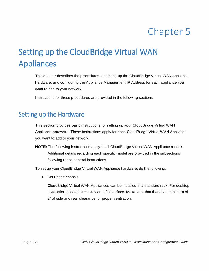
CB 1000 Management Port
The CB 1000 Management Port is the bottom far right port labeled MGMT, on the back of the
chassis. The default IP Address for the Management Port is 192.168.100.1.
The following figure shows the location of the CB 1000 Management Port.
Figure 8. CB 1000 Management Port.
Page 33
P a g e | 33 Citrix CloudBridge Virtual WAN 8.0 Installation and Configuration Guide
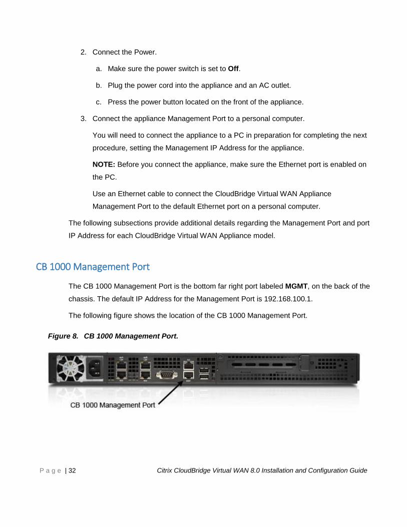
CB 2000 Management Port
The CB 2000 Management Port is the bottom-left port labeled 0/1, on the front of the chassis.
The default IP Address for the Management Port is 192.168.100.1.
The following figure shows the location of the CB 2000 Management Port.
Figure 9. CB 2000 Management Port.
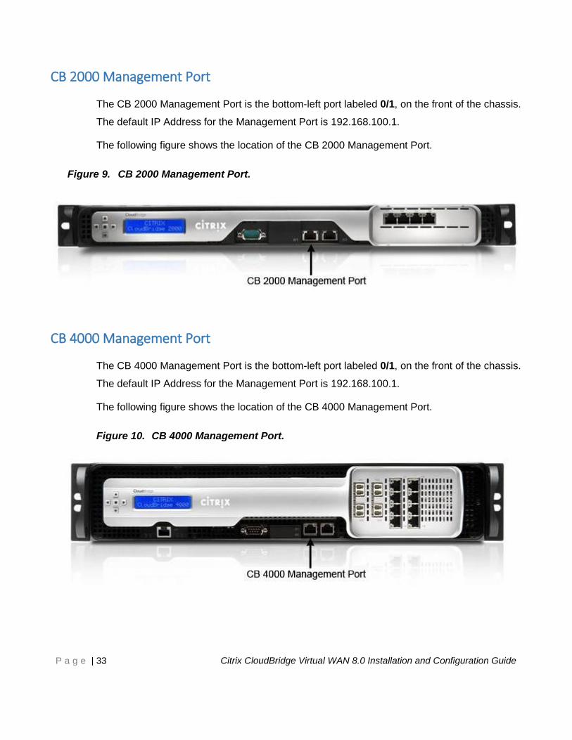
CB 4000 Management Port
The CB 4000 Management Port is the bottom-left port labeled 0/1, on the front of the chassis.
The default IP Address for the Management Port is 192.168.100.1.
The following figure shows the location of the CB 4000 Management Port.
Figure 10. CB 4000 Management Port.
Page 34
P a g e | 34 Citrix CloudBridge Virtual WAN 8.0 Installation and Configuration Guide
Setting the Management IP Addresses for the Appliances
To enable remote access to a CloudBridge Virtual WAN appliance, you must specify a unique
Management IP Address for the appliance. To do so, you must first connect the appliance to
a personal computer. You can then open a browser on the PC and connect directly to the
Management Web Interface on the appliance, where you can set the Management IP
Address for that appliance. The Management IP Address must be unique for each appliance.
NOTE: You must repeat this process for each appliance you want to add to your network.
To configure the Management IP Address for an appliance, do the following:
1. Connect the appliance to a PC.
If you have not already done so, connect one end of an Ethernet cable to the
Management Port on the appliance, and the other end to the default Ethernet port on
the PC.
NOTE: Make sure the Ethernet port is enabled on the PC you are using to connect to
the appliance.
2. Record the current Ethernet port settings for the PC you will be using to set the
appliance Management IP Address.
You will need to change the Ethernet port settings on the PC before you can set the
appliance Management IP Address. Be sure to record the original settings so you can
restore them after configuring the Management IP Address.
3. Change the IP Address for the PC.
On the PC, open your network interface settings and change the IP Address for your
PC to the following:
192.168.100.50
4. Change the Subnet Mask setting on your PC to the following:
255.255.0.0
Page 35
P a g e | 35 Citrix CloudBridge Virtual WAN 8.0 Installation and Configuration Guide
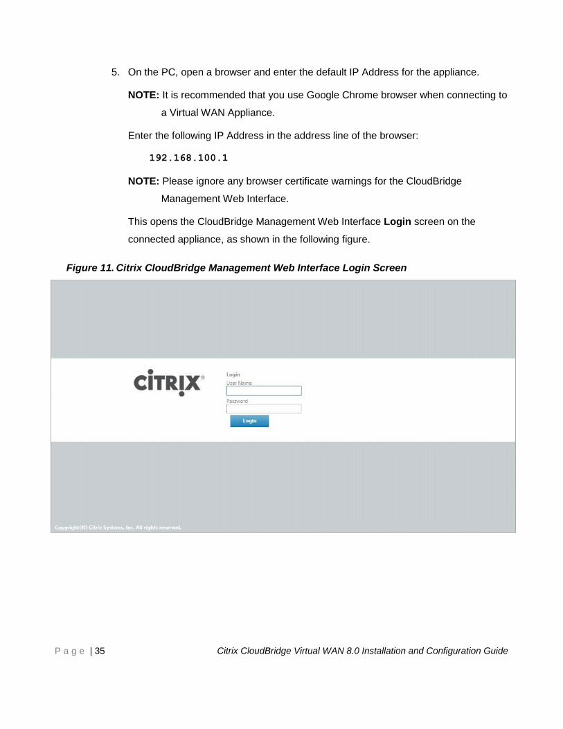
5. On the PC, open a browser and enter the default IP Address for the appliance.
NOTE: It is recommended that you use Google Chrome browser when connecting to
a Virtual WAN Appliance.
Enter the following IP Address in the address line of the browser:
192.168.100.1
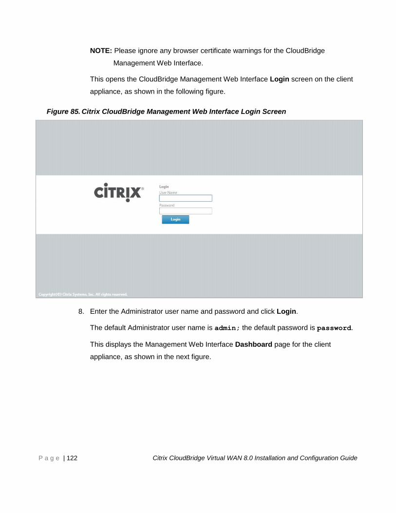
NOTE: Please ignore any browser certificate warnings for the CloudBridge
Management Web Interface.
This opens the CloudBridge Management Web Interface Login screen on the
connected appliance, as shown in the following figure.
Figure 11. Citrix CloudBridge Management Web Interface Login Screen
Page 36
P a g e | 36 Citrix CloudBridge Virtual WAN 8.0 Installation and Configuration Guide
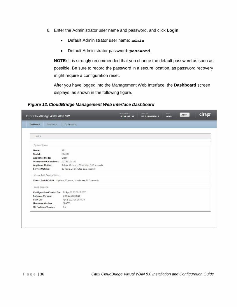
6. Enter the Administrator user name and password, and click Login.
Default Administrator user name: admin
Default Administrator password: password
NOTE: It is strongly recommended that you change the default password as soon as
possible. Be sure to record the password in a secure location, as password recovery
might require a configuration reset.
After you have logged into the Management Web Interface, the Dashboard screen
displays, as shown in the following figure.
Figure 12. CloudBridge Management Web Interface Dashboard
Page 37
P a g e | 37 Citrix CloudBridge Virtual WAN 8.0 Installation and Configuration Guide
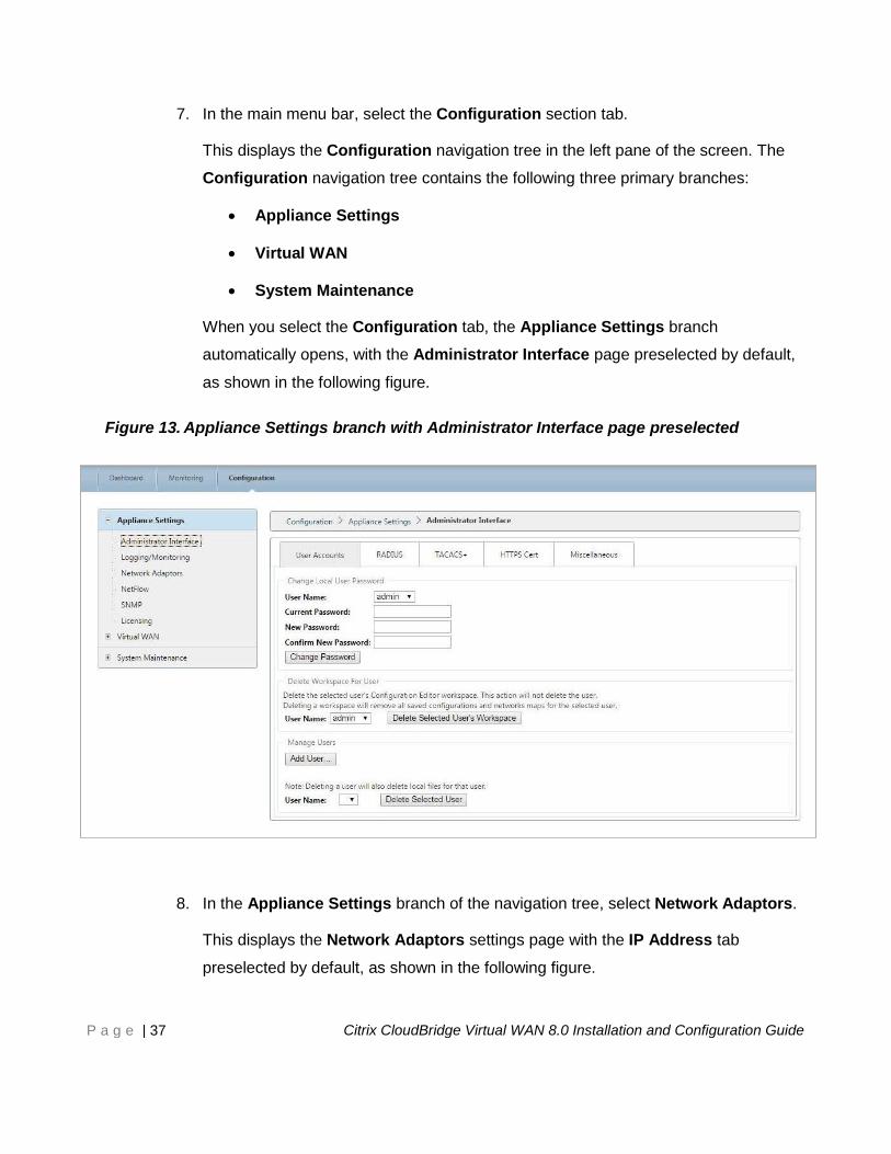
7. In the main menu bar, select the Configuration section tab.
This displays the Configuration navigation tree in the left pane of the screen. The
Configuration navigation tree contains the following three primary branches:
Appliance Settings
Virtual WAN
System Maintenance
When you select the Configuration tab, the Appliance Settings branch
automatically opens, with the Administrator Interface page preselected by default,
as shown in the following figure.
Figure 13. Appliance Settings branch with Administrator Interface page preselected
8. In the Appliance Settings branch of the navigation tree, select Network Adaptors.
This displays the Network Adaptors settings page with the IP Address tab
preselected by default, as shown in the following figure.
Page 38
P a g e | 38 Citrix CloudBridge Virtual WAN 8.0 Installation and Configuration Guide
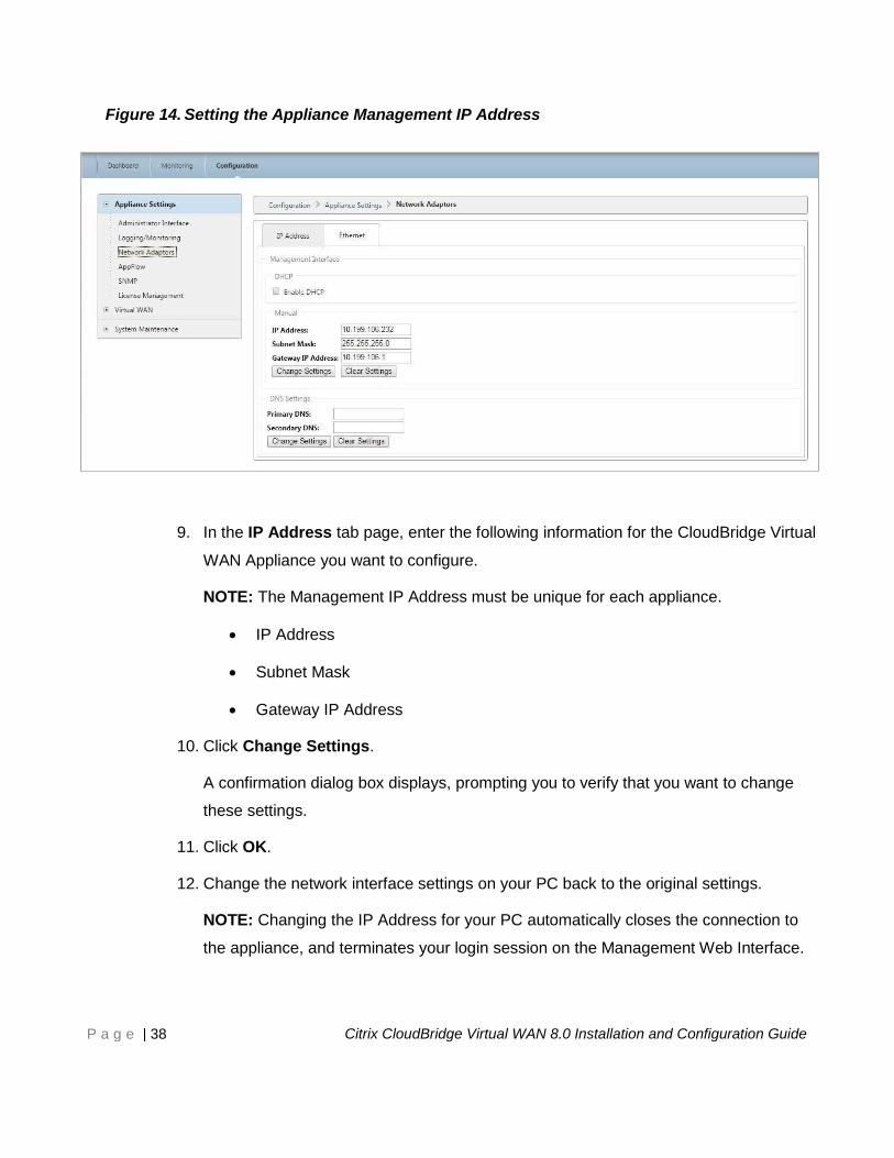
Figure 14. Setting the Appliance Management IP Address
9. In the IP Address tab page, enter the following information for the CloudBridge Virtual
WAN Appliance you want to configure.
NOTE: The Management IP Address must be unique for each appliance.
IP Address
Subnet Mask
Gateway IP Address
10. Click Change Settings.
A confirmation dialog box displays, prompting you to verify that you want to change
these settings.
11. Click OK.
12. Change the network interface settings on your PC back to the original settings.
NOTE: Changing the IP Address for your PC automatically closes the connection to
the appliance, and terminates your login session on the Management Web Interface.
Page 39
P a g e | 39 Citrix CloudBridge Virtual WAN 8.0 Installation and Configuration Guide
13. Disconnect the appliance from the PC and connect the appliance to your network
router or switch.
Disconnect the Ethernet cable from the PC, but do not disconnect it from your
appliance. Connect the free end of the cable to your network router or switch.
The Virtual WAN Appliance is now connected to and available on your network.
14. Test the connection.
On a PC connected to your network, open a browser and enter the Management
IP Address you just configured for the appliance.
If the connection is successful, this displays the Login screen for the CloudBridge
Virtual WAN Management Web Interface on the appliance you just configured.
You have now set the Management IP Address of your Virtual WAN Appliance, and can
connect to the appliance from any location in your network.
NOTE: You must repeat these steps for every CloudBridge Virtual WAN Appliance you want
to add to your network. The Management IP Address must be unique for each
appliance.
NOTE: If you have not already downloaded the CloudBridge Virtual WAN software packages
to a PC connected to your network, please do so now. For information on acquiring
and downloading the software packages, see the section entitled, “CloudBridge
Virtual WAN Software Requirements,” in the chapter entitled, “Before You Begin,”
earlier in this guide.
The next step is to create and configure the Master Control Node (MCN).
Page 40
P a g e | 40 Citrix CloudBridge Virtual WAN 8.0 Installation and Configuration Guide
Setting up the Master Control Node (MCN) Site This chapter provides basic instructions for creating and deploying the MCN.
The steps involved to complete this process are as follows:
1. Specify the appliance that will act as the Master Control Node (MCN).
2. Add the MCN site.
3. Configure the Virtual Interface Groups for the MCN site.
4. Configure the Virtual IP Addresses for the MCN site.
5. Configure the WAN links for the MCN site.
6. Configure the Access Interfaces for the MCN site.
7. Configure the routes for the MCN site.
8. (Optional) Configure High Availability for the MCN site.
9. (Optional) Configure Virtual WAN security and encryption.
10. Save the MCN site configuration.
Instructions for each of these tasks are provided in the following sections.
Page 41
P a g e | 41 Citrix CloudBridge Virtual WAN 8.0 Installation and Configuration Guide
Promote the Head End Appliance to the Role of MCN
The CloudBridge Virtual WAN Master Control Node (MCN) serves as the distribution point for
the initial system configuration and any subsequent configuration changes. In addition, you
conduct most upgrade procedures through the Management Web Interface on the MCN.
To set up the MCN, you first must promote the head end Virtual WAN Appliance—typically,
the appliance deployed at your Enterprise data center—from the default role of client to the
role of MCN. To do this, you must place the Management Web Interface on the appliance you
are promoting into MCN Console mode. Instructions are provided below.
To switch the Management Web Interface to MCN Console mode, do the following:
1. Log into the Management Web Interface on the appliance you want to configure as
the MCN.
2. Click Configuration in the main menu bar of the Management Web Interface main
screen (blue bar at the top of the page).
3. In the navigation tree (left pane), open the Appliance Settings branch and click
Administrator Interface.
This displays the Administrator Interface page in the middle pane.
4. Select the Miscellaneous tab.
This displays the Miscellaneous administrative settings page, as shown in the
following figure.
Page 42
P a g e | 42 Citrix CloudBridge Virtual WAN 8.0 Installation and Configuration Guide
Figure 15. Administrator Interface > Miscellaneous tab page
At the bottom of the Miscellaneous tab page is the Switch to [Client | MCN]
Console section. This section contains the Switch Console button for toggling
between appliance console modes.
The section heading indicates the current console mode, as follows:
When in Client Console mode (default), the section heading is Switch to
MCN Console.
When in MCN Console mode, the section heading is Switch to Client
Console.
By default, a new appliance is set to Client Console mode.
MCN Console mode enables the Configuration Editor branch in the navigation tree.
The Configuration Editor is available on the MCN appliance, only.
NOTE: Before proceeding to the next step, make sure that the appliance is still set to
the default (Client Console mode). The section heading should be: Switch to
MCN Console.
5. Click Switch Mode to set the appliance mode to MCN Console mode.
The next step is to add the MCN site to the Sites table, and begin to configure the new
MCN site.
Page 43
P a g e | 43 Citrix CloudBridge Virtual WAN 8.0 Installation and Configuration Guide
Adding the MCN Site
To add and begin configuring the MCN appliance site, do the following:
1. In the navigation tree, open the Virtual WAN branch and select Configuration
Editor.
This displays the Configuration Editor main page (middle pane), as shown in the
following figure.
NOTE: The Configuration Editor is available in MCN Console mode, only. If the
Configuration Editor option is not available in the Virtual WAN branch of the
navigation tree, please refer to the previous section, “Specifying the MCN,” for
instructions on changing the console mode.
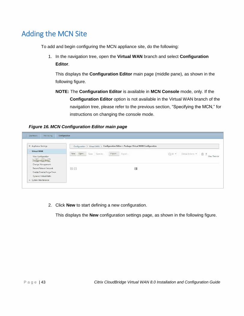
Figure 16. MCN Configuration Editor main page
2. Click New to start defining a new configuration.
This displays the New configuration settings page, as shown in the following figure.
Page 44
P a g e | 44 Citrix CloudBridge Virtual WAN 8.0 Installation and Configuration Guide
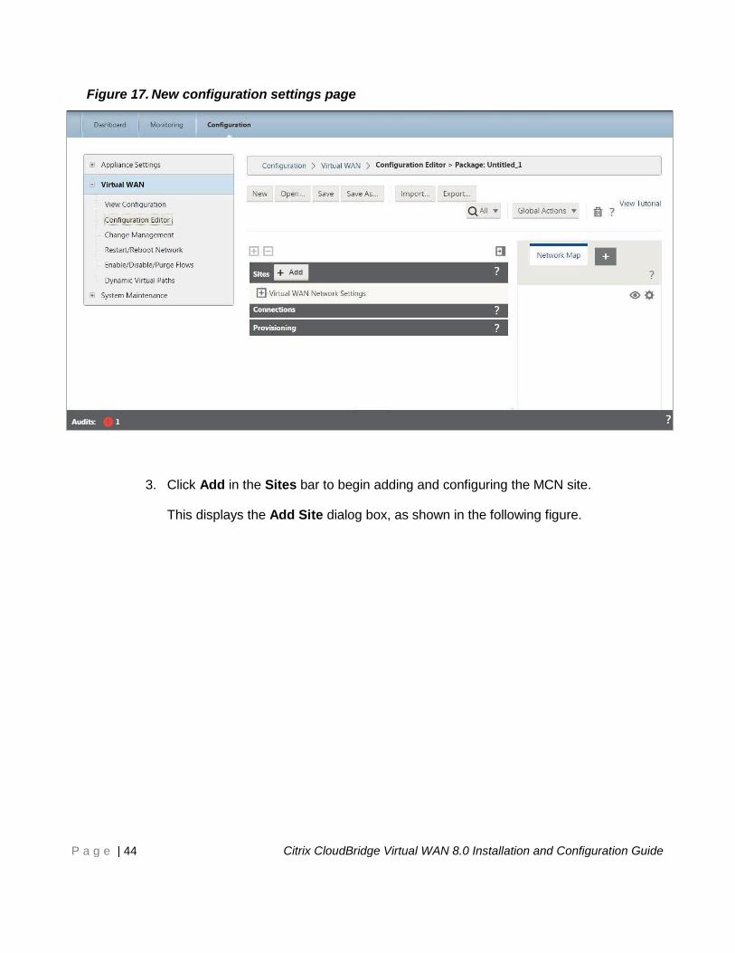
Figure 17. New configuration settings page
3. Click Add in the Sites bar to begin adding and configuring the MCN site.
This displays the Add Site dialog box, as shown in the following figure.
Page 45
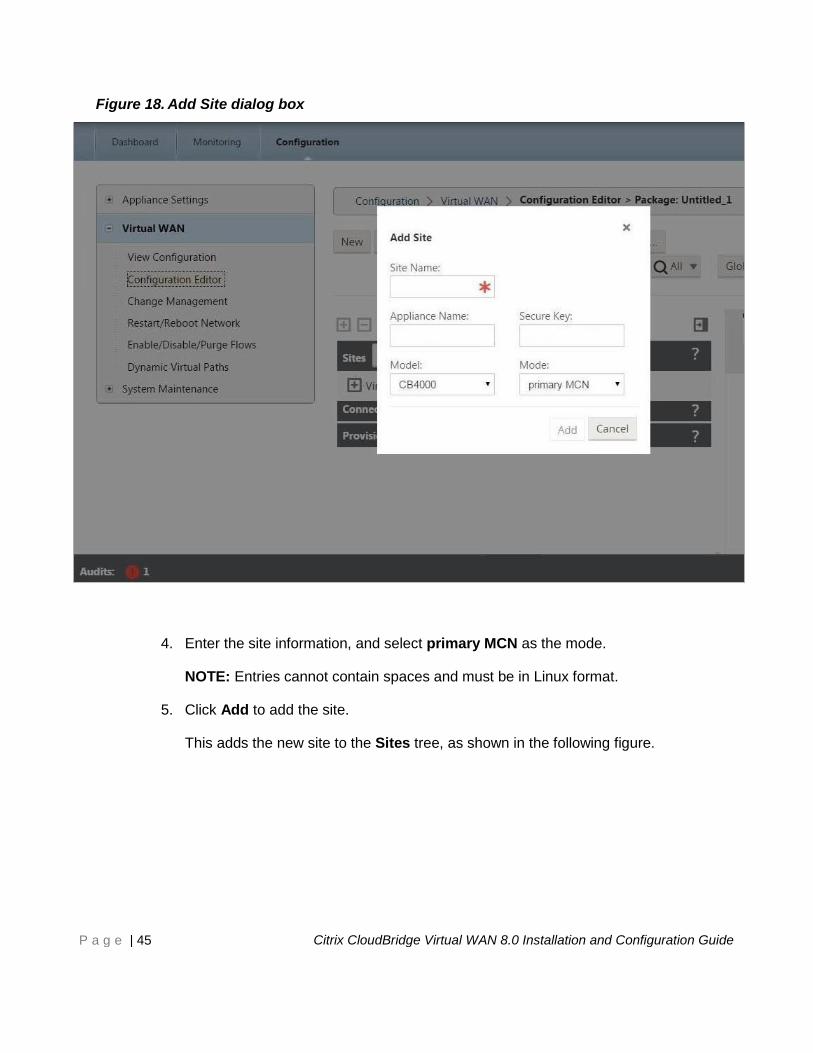
P a g e | 45 Citrix CloudBridge Virtual WAN 8.0 Installation and Configuration Guide
Figure 18. Add Site dialog box
4. Enter the site information, and select primary MCN as the mode.
NOTE: Entries cannot contain spaces and must be in Linux format.
5. Click Add to add the site.
This adds the new site to the Sites tree, as shown in the following figure.
Page 46
P a g e | 46 Citrix CloudBridge Virtual WAN 8.0 Installation and Configuration Guide
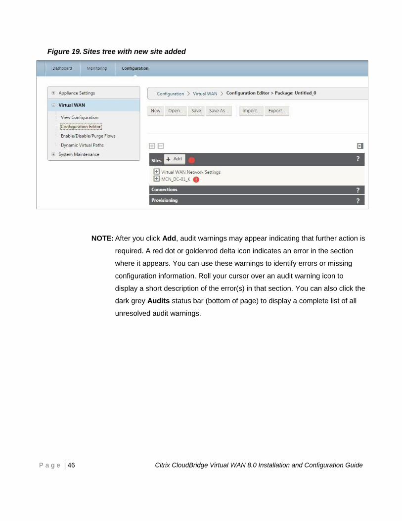
Figure 19. Sites tree with new site added
NOTE: After you click Add, audit warnings may appear indicating that further action is
required. A red dot or goldenrod delta icon indicates an error in the section
where it appears. You can use these warnings to identify errors or missing
configuration information. Roll your cursor over an audit warning icon to
display a short description of the error(s) in that section. You can also click the
dark grey Audits status bar (bottom of page) to display a complete list of all
unresolved audit warnings.
Page 47
P a g e | 47 Citrix CloudBridge Virtual WAN 8.0 Installation and Configuration Guide
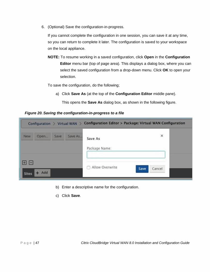
6. (Optional) Save the configuration-in-progress.
If you cannot complete the configuration in one session, you can save it at any time,
so you can return to complete it later. The configuration is saved to your workspace
on the local appliance.
NOTE: To resume working in a saved configuration, click Open in the Configuration
Editor menu bar (top of page area). This displays a dialog box, where you can
select the saved configuration from a drop-down menu. Click OK to open your
selection.
To save the configuration, do the following;
a) Click Save As (at the top of the Configuration Editor middle pane).
This opens the Save As dialog box, as shown in the following figure.
Figure 20. Saving the configuration-in-progress to a file
b) Enter a descriptive name for the configuration.
c) Click Save.
Page 48
P a g e | 48 Citrix CloudBridge Virtual WAN 8.0 Installation and Configuration Guide
Configuring the Virtual Interface Groups for the MCN Site
After adding the new site, the next step is to create and configure the Virtual Interface Groups
for the site.
The following are some guidelines for configuring Virtual Interface groups:
Use logical names that will best describe the group.
Trusted networks are networks that are protected behind a Firewall.
Virtual Interfaces associate interfaces to Fail to Wire (FTW) pairs.
Single WAN interfaces cannot be in an FTW pair.
NOTE: For additional guidelines and information on configuring Virtual Interface Groups,
please refer to the CloudBridge Virtual WAN 8.0 Deployment Planning Guide.
To add a Virtual Interface Group to the new site, do the following:
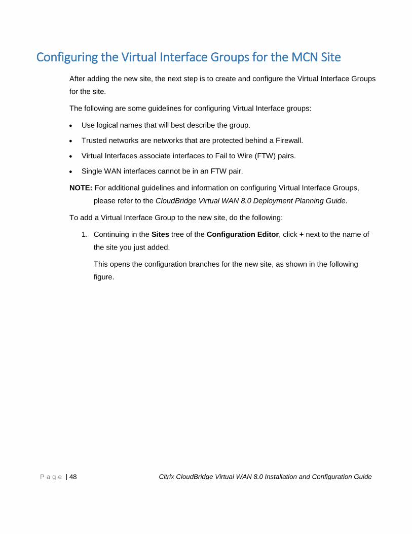
1. Continuing in the Sites tree of the Configuration Editor, click + next to the name of
the site you just added.
This opens the configuration branches for the new site, as shown in the following
figure.
Page 49
P a g e | 49 Citrix CloudBridge Virtual WAN 8.0 Installation and Configuration Guide
Figure 21. New site configuration tree
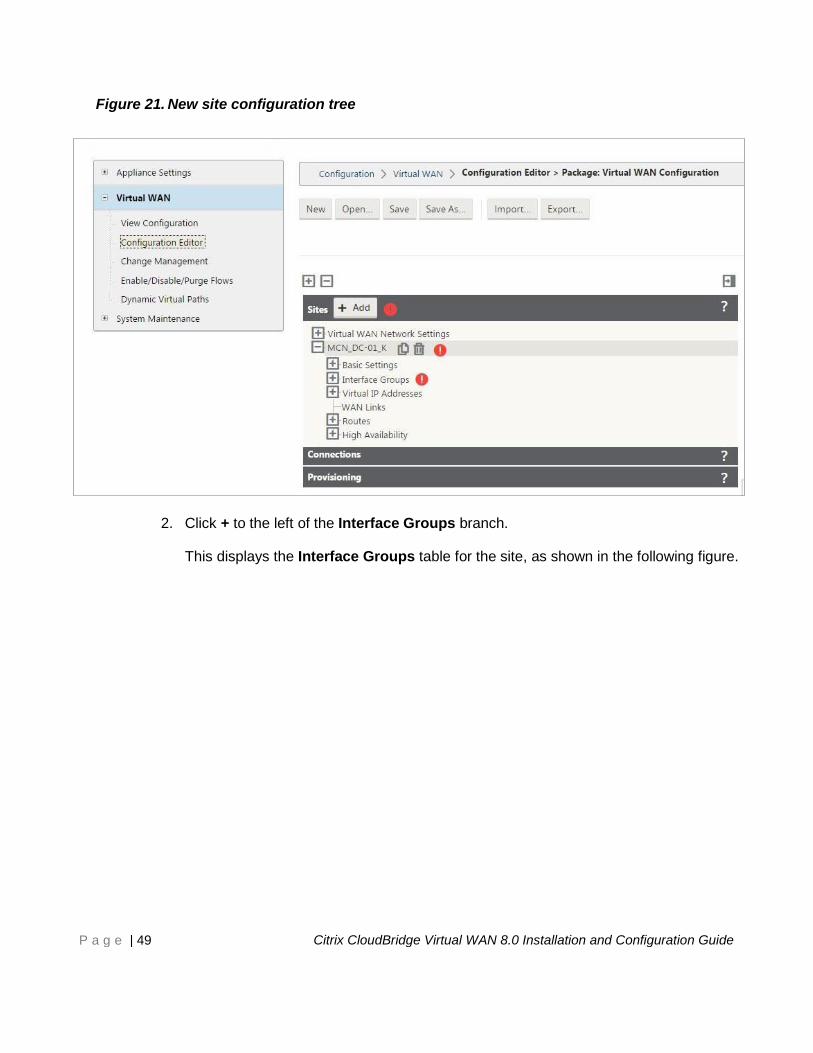
2. Click + to the left of the Interface Groups branch.
This displays the Interface Groups table for the site, as shown in the following figure.
Page 50
P a g e | 50 Citrix CloudBridge Virtual WAN 8.0 Installation and Configuration Guide
Figure 22. Interface Groups table for the new site
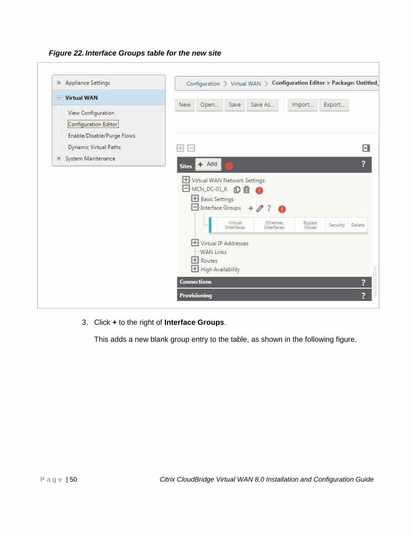
3. Click + to the right of Interface Groups.
This adds a new blank group entry to the table, as shown in the following figure.
Page 51
P a g e | 51 Citrix CloudBridge Virtual WAN 8.0 Installation and Configuration Guide
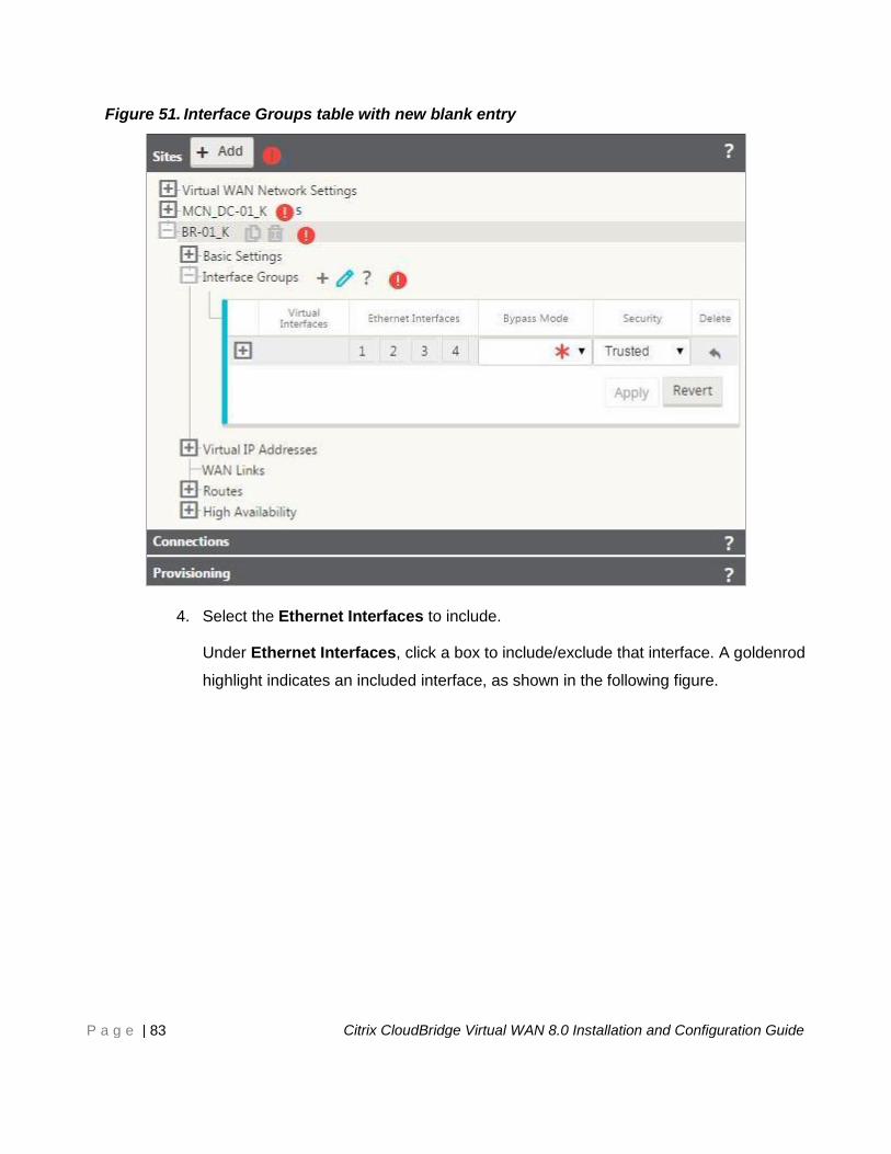
Figure 23. Interface Groups table with new blank entry
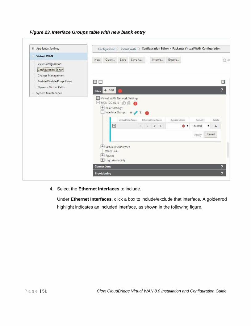
4. Select the Ethernet Interfaces to include.
Under Ethernet Interfaces, click a box to include/exclude that interface. A goldenrod
highlight indicates an included interface, as shown in the following figure.
Page 52
P a g e | 52 Citrix CloudBridge Virtual WAN 8.0 Installation and Configuration Guide
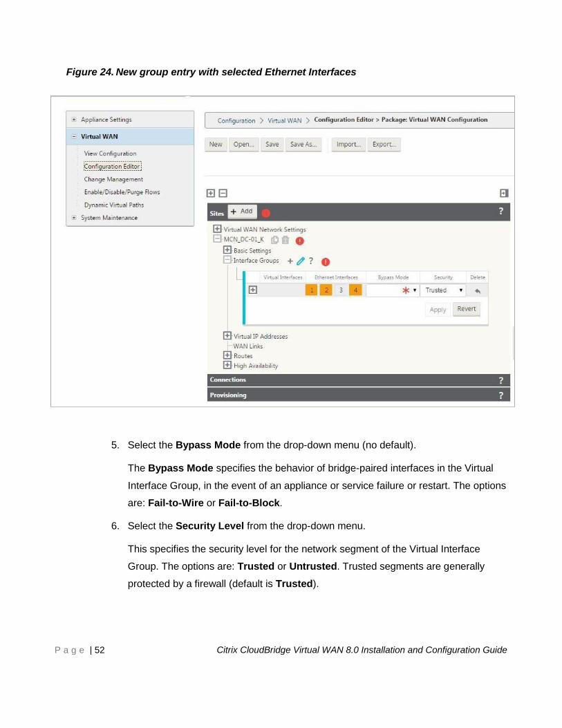
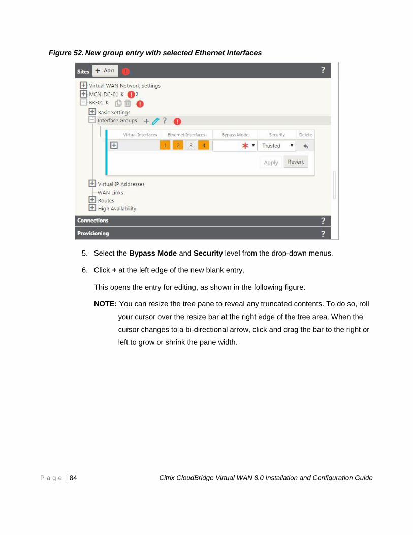
Figure 24. New group entry with selected Ethernet Interfaces
5. Select the Bypass Mode from the drop-down menu (no default).
The Bypass Mode specifies the behavior of bridge-paired interfaces in the Virtual
Interface Group, in the event of an appliance or service failure or restart. The options
are: Fail-to-Wire or Fail-to-Block.
6. Select the Security Level from the drop-down menu.
This specifies the security level for the network segment of the Virtual Interface
Group. The options are: Trusted or Untrusted. Trusted segments are generally
protected by a firewall (default is Trusted).
Page 53
P a g e | 53 Citrix CloudBridge Virtual WAN 8.0 Installation and Configuration Guide
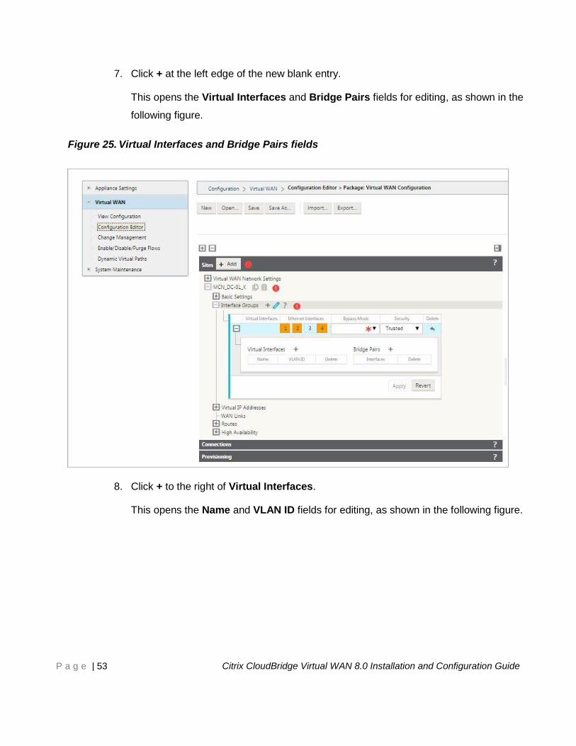
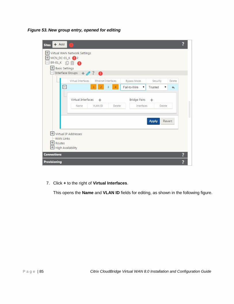
7. Click + at the left edge of the new blank entry.
This opens the Virtual Interfaces and Bridge Pairs fields for editing, as shown in the
following figure.
Figure 25. Virtual Interfaces and Bridge Pairs fields
8. Click + to the right of Virtual Interfaces.
This opens the Name and VLAN ID fields for editing, as shown in the following figure.
Page 54
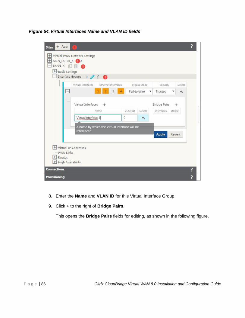
P a g e | 54 Citrix CloudBridge Virtual WAN 8.0 Installation and Configuration Guide
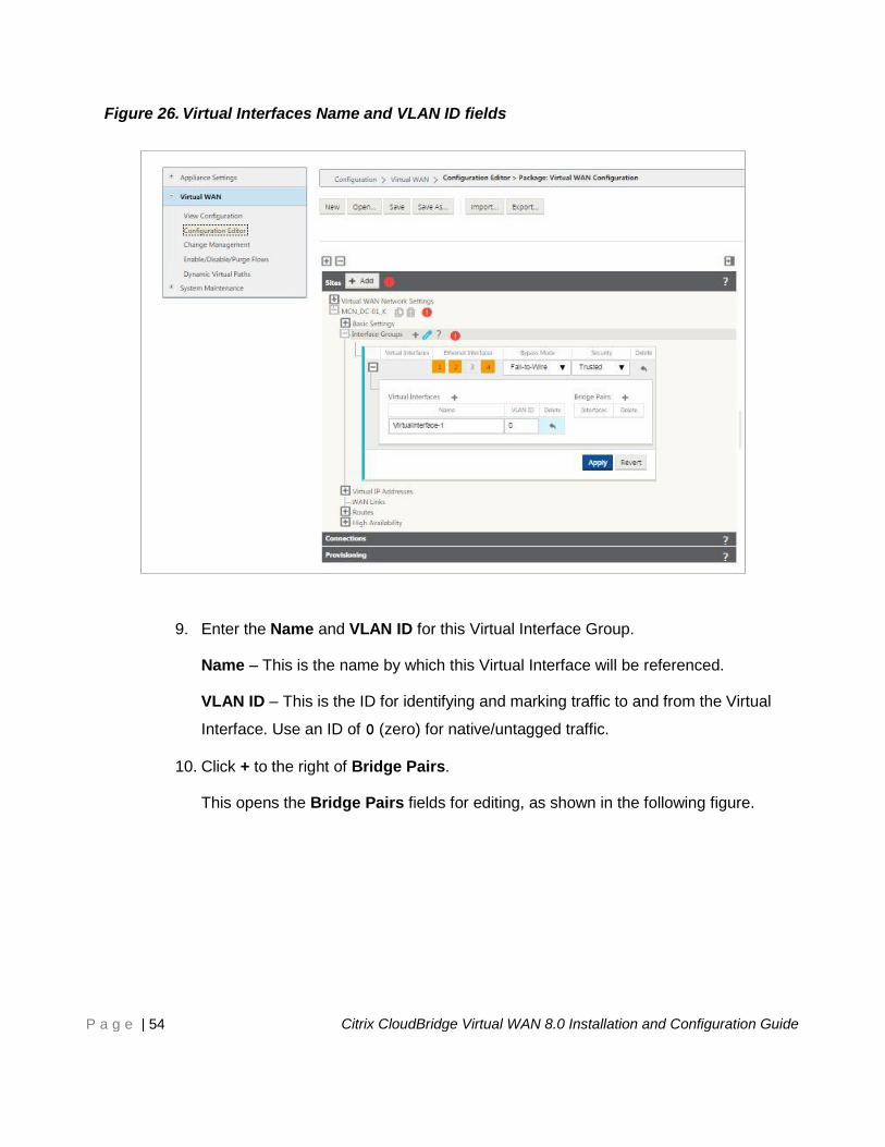
Figure 26. Virtual Interfaces Name and VLAN ID fields
9. Enter the Name and VLAN ID for this Virtual Interface Group.
Name – This is the name by which this Virtual Interface will be referenced.
VLAN ID – This is the ID for identifying and marking traffic to and from the Virtual
Interface. Use an ID of 0 (zero) for native/untagged traffic.
10. Click + to the right of Bridge Pairs.
This opens the Bridge Pairs fields for editing, as shown in the following figure.
Page 55
P a g e | 55 Citrix CloudBridge Virtual WAN 8.0 Installation and Configuration Guide
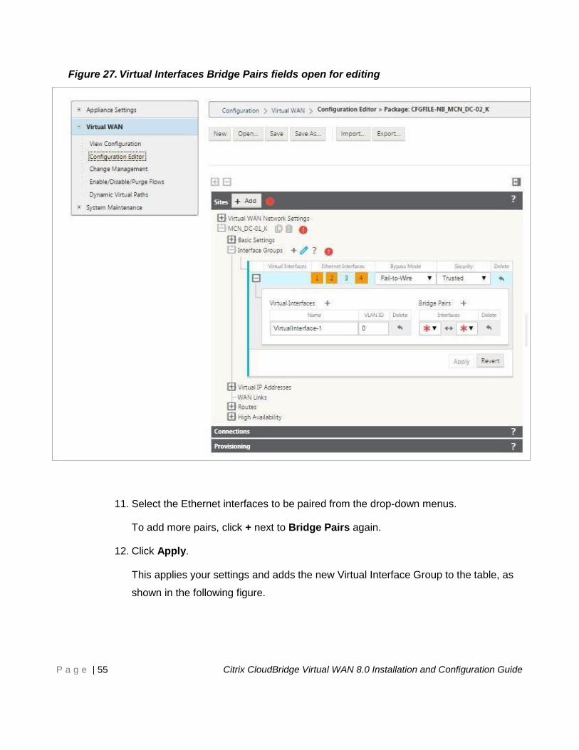
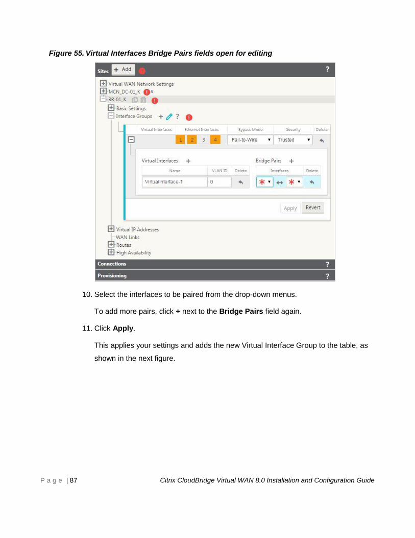
Figure 27. Virtual Interfaces Bridge Pairs fields open for editing
11. Select the Ethernet interfaces to be paired from the drop-down menus.
To add more pairs, click + next to Bridge Pairs again.
12. Click Apply.
This applies your settings and adds the new Virtual Interface Group to the table, as
shown in the following figure.
Page 56
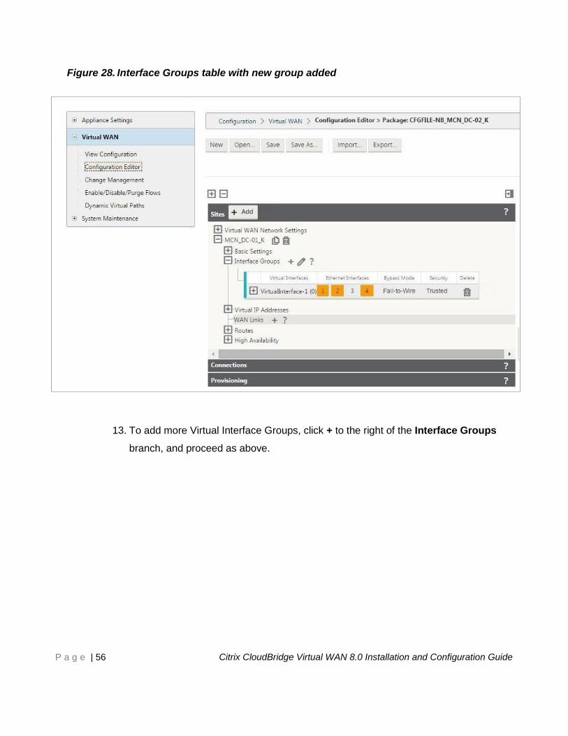
P a g e | 56 Citrix CloudBridge Virtual WAN 8.0 Installation and Configuration Guide
Figure 28. Interface Groups table with new group added
13. To add more Virtual Interface Groups, click + to the right of the Interface Groups
branch, and proceed as above.
Page 57
P a g e | 57 Citrix CloudBridge Virtual WAN 8.0 Installation and Configuration Guide
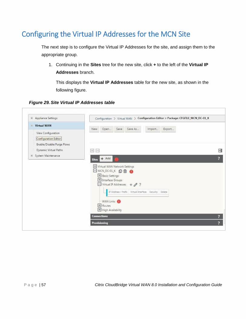
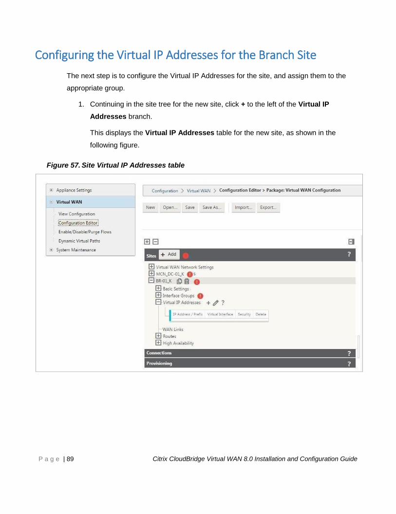
Configuring the Virtual IP Addresses for the MCN Site
The next step is to configure the Virtual IP Addresses for the site, and assign them to the
appropriate group.
1. Continuing in the Sites tree for the new site, click + to the left of the Virtual IP
Addresses branch.
This displays the Virtual IP Addresses table for the new site, as shown in the
following figure.
Figure 29. Site Virtual IP Addresses table
Page 58
P a g e | 58 Citrix CloudBridge Virtual WAN 8.0 Installation and Configuration Guide
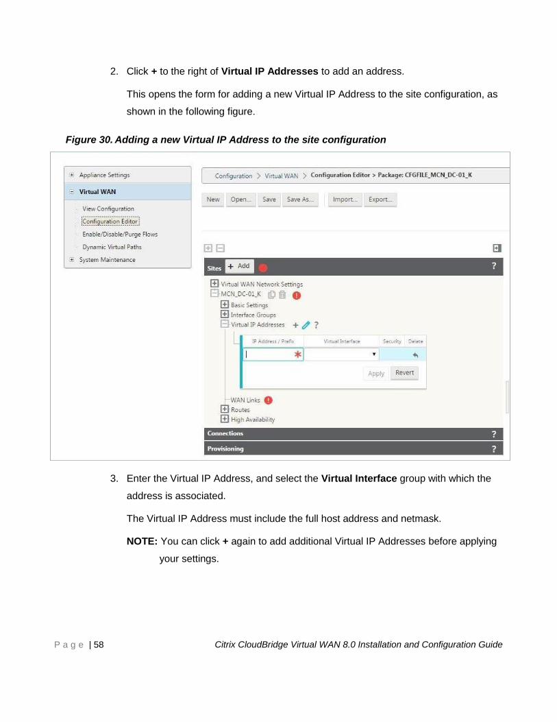
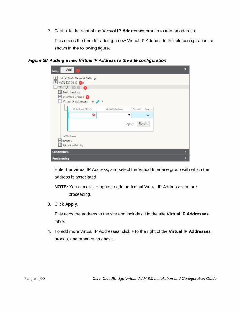
2. Click + to the right of Virtual IP Addresses to add an address.
This opens the form for adding a new Virtual IP Address to the site configuration, as
shown in the following figure.
Figure 30. Adding a new Virtual IP Address to the site configuration
3. Enter the Virtual IP Address, and select the Virtual Interface group with which the
address is associated.
The Virtual IP Address must include the full host address and netmask.
NOTE: You can click + again to add additional Virtual IP Addresses before applying
your settings.
Page 59
P a g e | 59 Citrix CloudBridge Virtual WAN 8.0 Installation and Configuration Guide
4. Click Apply.
This adds the address to the site and includes it in the site Virtual IP Addresses
table.
5. To add more Virtual IP Addresses, click + to the right of the Virtual IP Addresses
branch, and proceed as above.
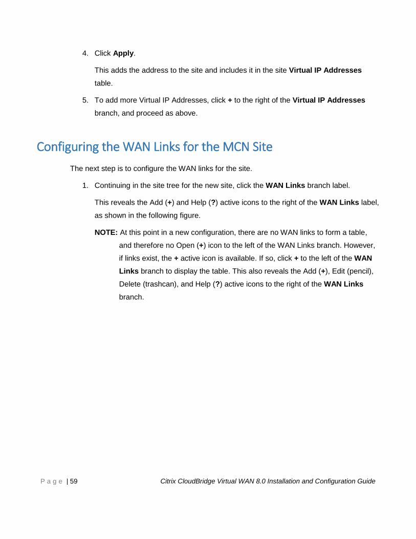
Configuring the WAN Links for the MCN Site
The next step is to configure the WAN links for the site.
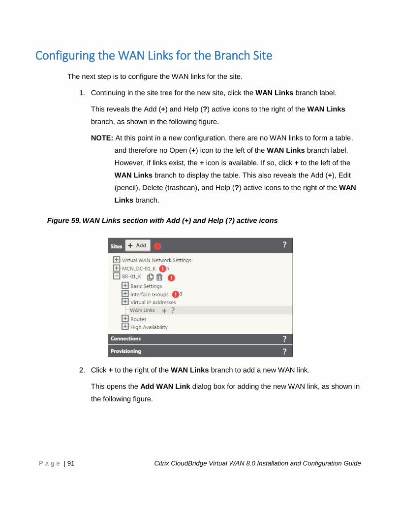
1. Continuing in the site tree for the new site, click the WAN Links branch label.
This reveals the Add (+) and Help (?) active icons to the right of the WAN Links label,
as shown in the following figure.
NOTE: At this point in a new configuration, there are no WAN links to form a table,
and therefore no Open (+) icon to the left of the WAN Links branch. However,
if links exist, the + active icon is available. If so, click + to the left of the WAN
Links branch to display the table. This also reveals the Add (+), Edit (pencil),
Delete (trashcan), and Help (?) active icons to the right of the WAN Links
branch.
Page 60
P a g e | 60 Citrix CloudBridge Virtual WAN 8.0 Installation and Configuration Guide
Figure 31. WAN Links section with Add (+) and Help (?) active icons
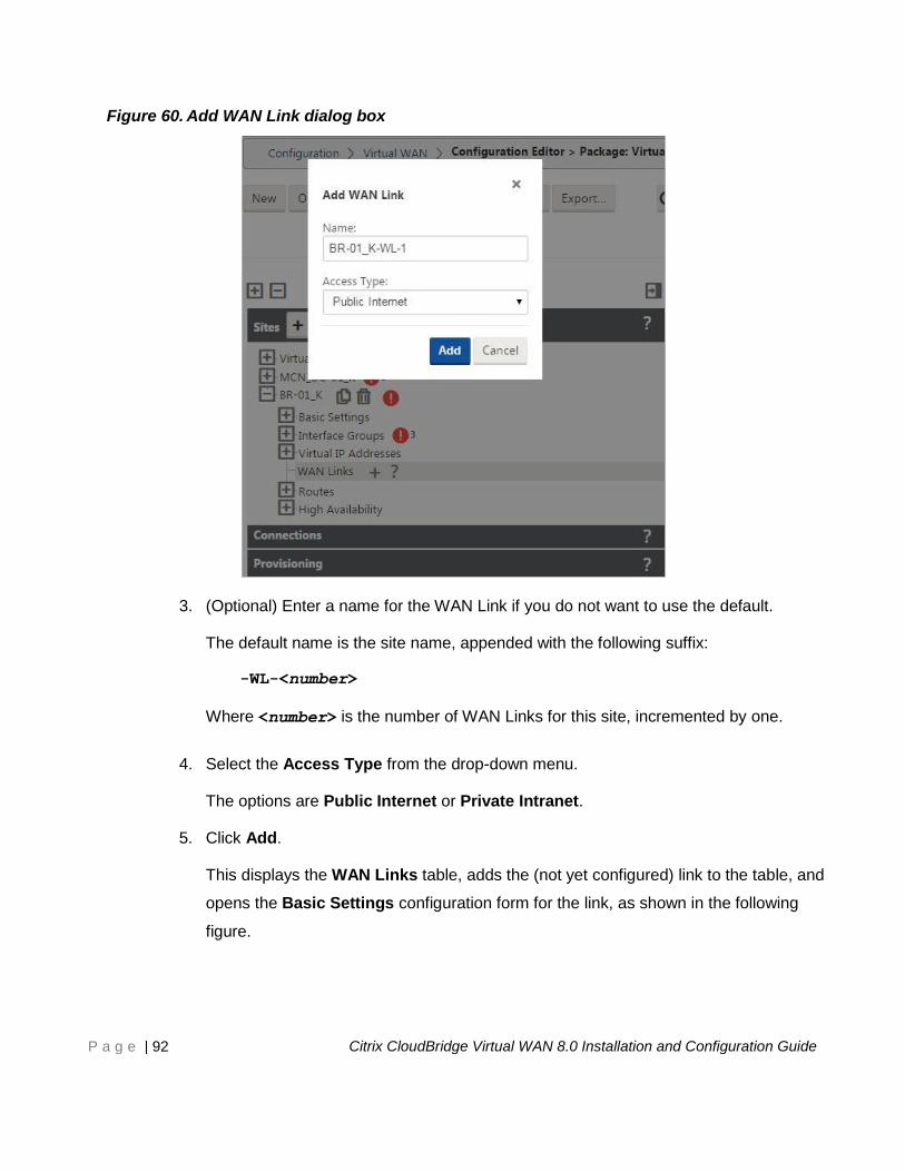
2. Click + to the right of the WAN Links branch to add a new WAN link.
This opens the Add WAN Link dialog box for adding the new WAN link, as shown in
the following figure.
Page 61
P a g e | 61 Citrix CloudBridge Virtual WAN 8.0 Installation and Configuration Guide
Figure 32. Add WAN Link dialog box
3. (Optional) Enter a name for the WAN Link if you do not want to use the default.
The default name is the site name, appended with the following suffix:
-WL-<number>
Where <number> is the number of WAN Links for this site, incremented by one.
4. Select the Access Type from the drop-down menu.
The options are Public Internet or Private Intranet.
5. Click Add.
This displays the WAN Links table, adds the un-configured link to the table, and
opens the Basic Settings configuration form for the link, as shown in the following
figure.
Page 62
P a g e | 62 Citrix CloudBridge Virtual WAN 8.0 Installation and Configuration Guide
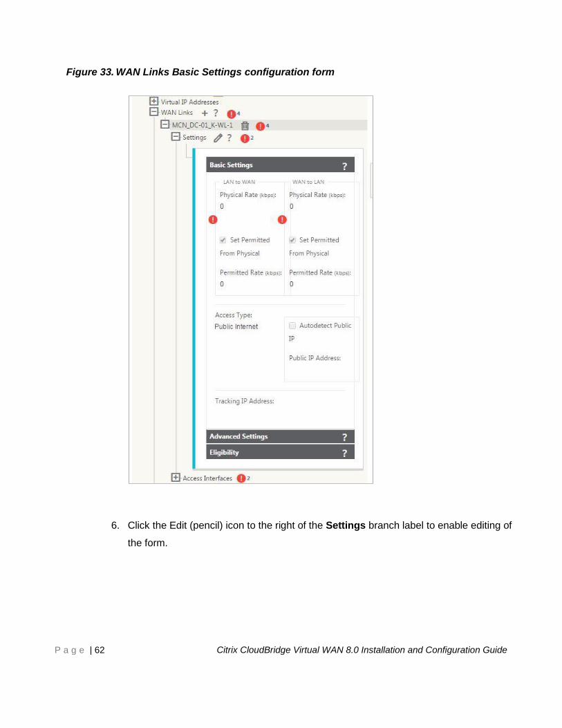
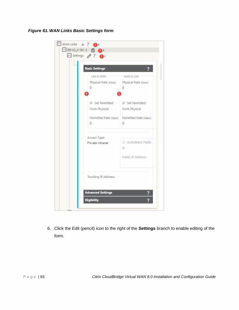
Figure 33. WAN Links Basic Settings configuration form
6. Click the Edit (pencil) icon to the right of the Settings branch label to enable editing of
the form.
Page 63
P a g e | 63 Citrix CloudBridge Virtual WAN 8.0 Installation and Configuration Guide
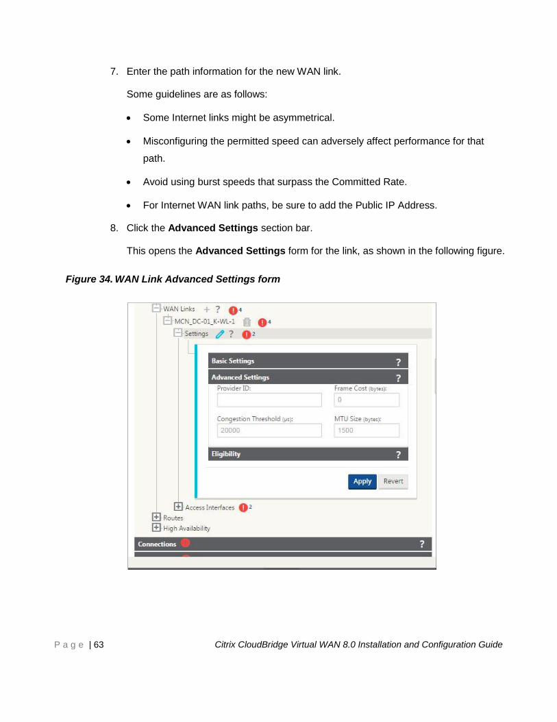
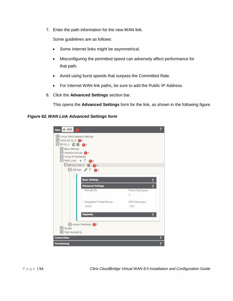
7. Enter the path information for the new WAN link.
Some guidelines are as follows:
Some Internet links might be asymmetrical.
Misconfiguring the permitted speed can adversely affect performance for that
path.
Avoid using burst speeds that surpass the Committed Rate.
For Internet WAN link paths, be sure to add the Public IP Address.
8. Click the Advanced Settings section bar.
This opens the Advanced Settings form for the link, as shown in the following figure.
Figure 34. WAN Link Advanced Settings form
Page 64
P a g e | 64 Citrix CloudBridge Virtual WAN 8.0 Installation and Configuration Guide
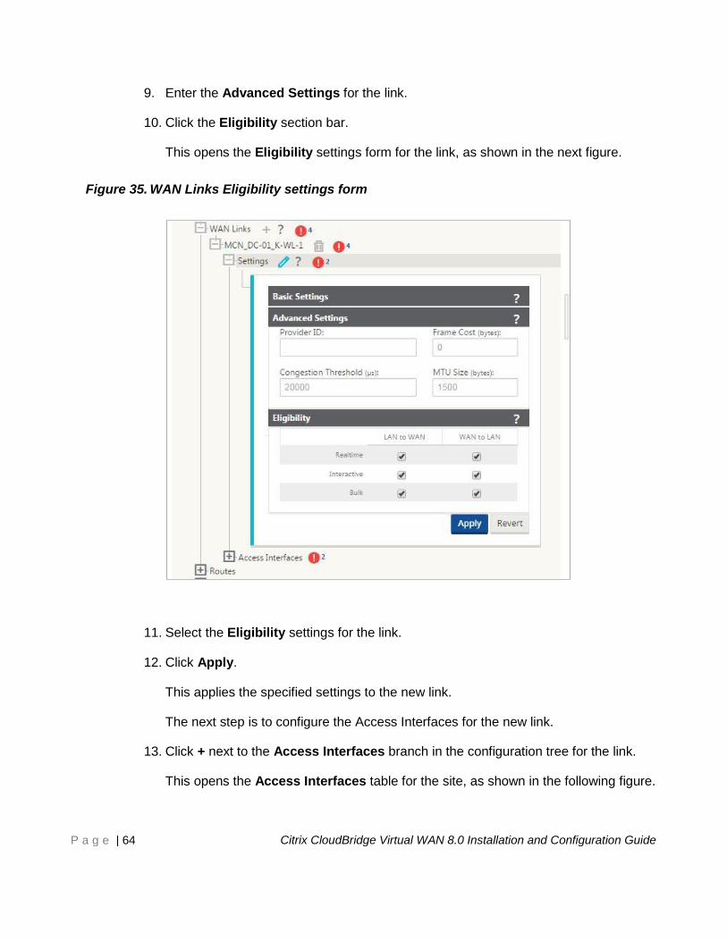
9. Enter the Advanced Settings for the link.
10. Click the Eligibility section bar.
This opens the Eligibility settings form for the link, as shown in the next figure.
Figure 35. WAN Links Eligibility settings form
11. Select the Eligibility settings for the link.
12. Click Apply.
This applies the specified settings to the new link.
The next step is to configure the Access Interfaces for the new link.
13. Click + next to the Access Interfaces branch in the configuration tree for the link.
This opens the Access Interfaces table for the site, as shown in the following figure.
Page 65
P a g e | 65 Citrix CloudBridge Virtual WAN 8.0 Installation and Configuration Guide
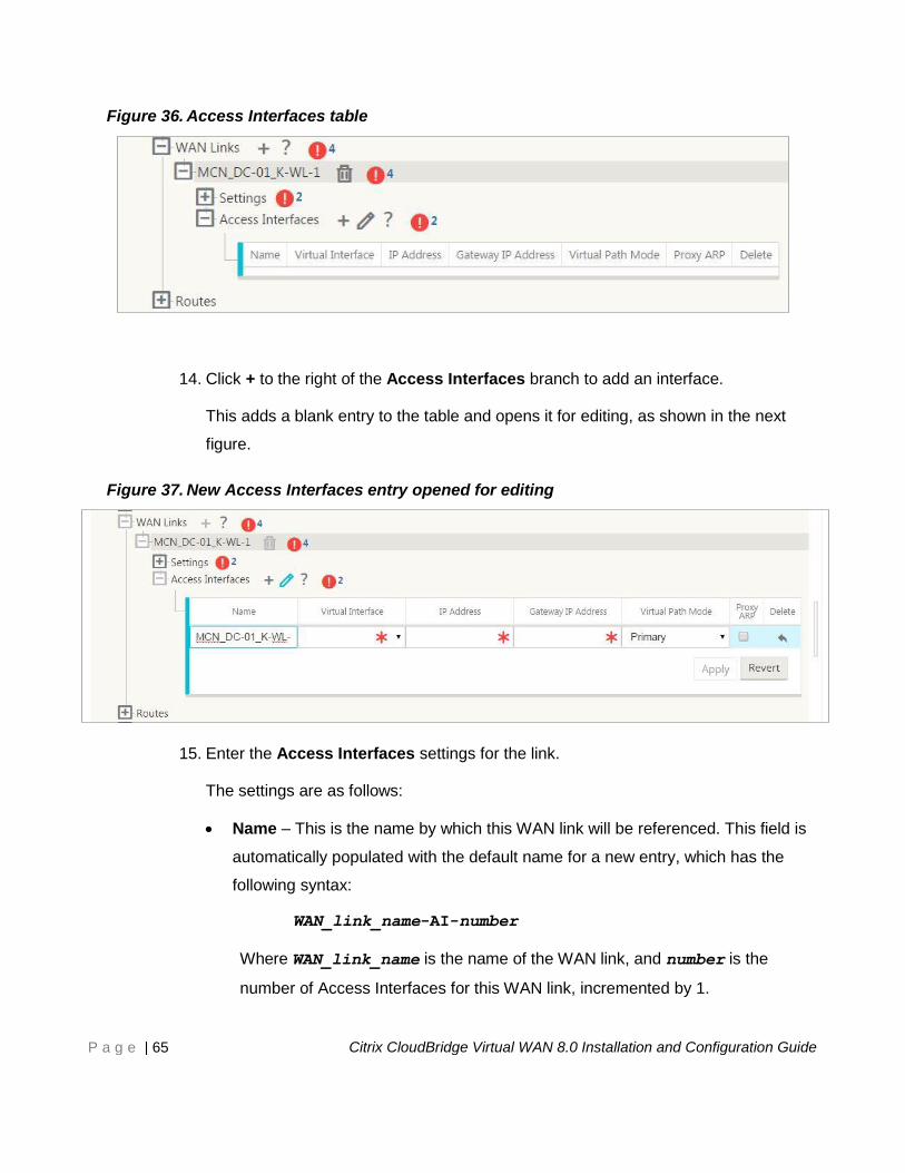
Figure 36. Access Interfaces table
14. Click + to the right of the Access Interfaces branch to add an interface.
This adds a blank entry to the table and opens it for editing, as shown in the next
figure.
Figure 37. New Access Interfaces entry opened for editing
15. Enter the Access Interfaces settings for the link.
The settings are as follows:
Name – This is the name by which this WAN link will be referenced. This field is
automatically populated with the default name for a new entry, which has the
following syntax:
WAN_link_name-AI-number
Where WAN_link_name is the name of the WAN link, and number is the
number of Access Interfaces for this WAN link, incremented by 1.
Page 66
P a g e | 66 Citrix CloudBridge Virtual WAN 8.0 Installation and Configuration Guide
The name of the Access Interface can be modified. If the name appears
truncated, you can place your cursor in the field, then click and hold and roll your
mouse right or left to see the truncated portion.
Virtual Interface – This is the Virtual Interface that this Access Interface will use.
IP Address – This is the IP Address for the Access Interface endpoint to the
WAN.
Gateway IP Address – This is the IP Address for the gateway router.
Virtual Path Mode – This specifies the priority for Virtual Path traffic on this WAN
link. The options are: Primary, Secondary, or Exclude. If set to Exclude, this
Access Interface will be used for Internet and Intranet traffic, only.
16. Click Apply.
You have now finished configuring the new WAN link. Repeat these steps to add and
configure additional WAN links for the site.
The next step is to add and configure the routes for the site.
Page 67
P a g e | 67 Citrix CloudBridge Virtual WAN 8.0 Installation and Configuration Guide
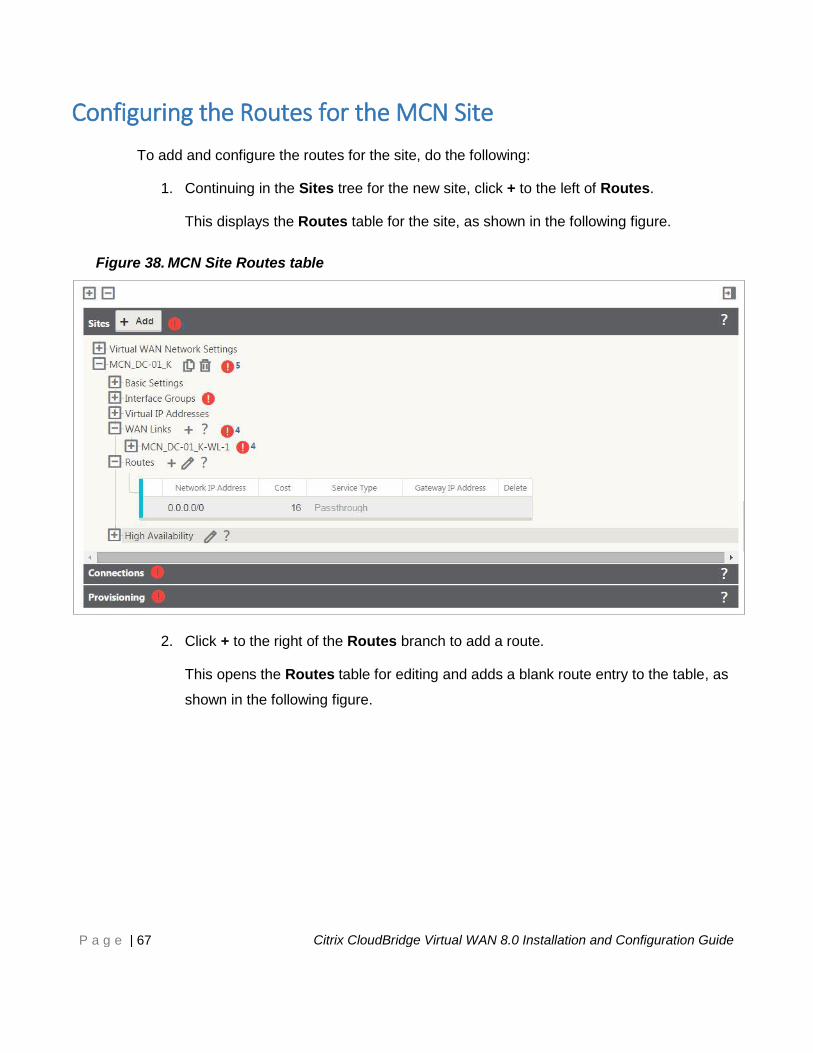
Configuring the Routes for the MCN Site
To add and configure the routes for the site, do the following:
1. Continuing in the Sites tree for the new site, click + to the left of Routes.
This displays the Routes table for the site, as shown in the following figure.
Figure 38. MCN Site Routes table
2. Click + to the right of the Routes branch to add a route.
This opens the Routes table for editing and adds a blank route entry to the table, as
shown in the following figure.
Page 68
P a g e | 68 Citrix CloudBridge Virtual WAN 8.0 Installation and Configuration Guide
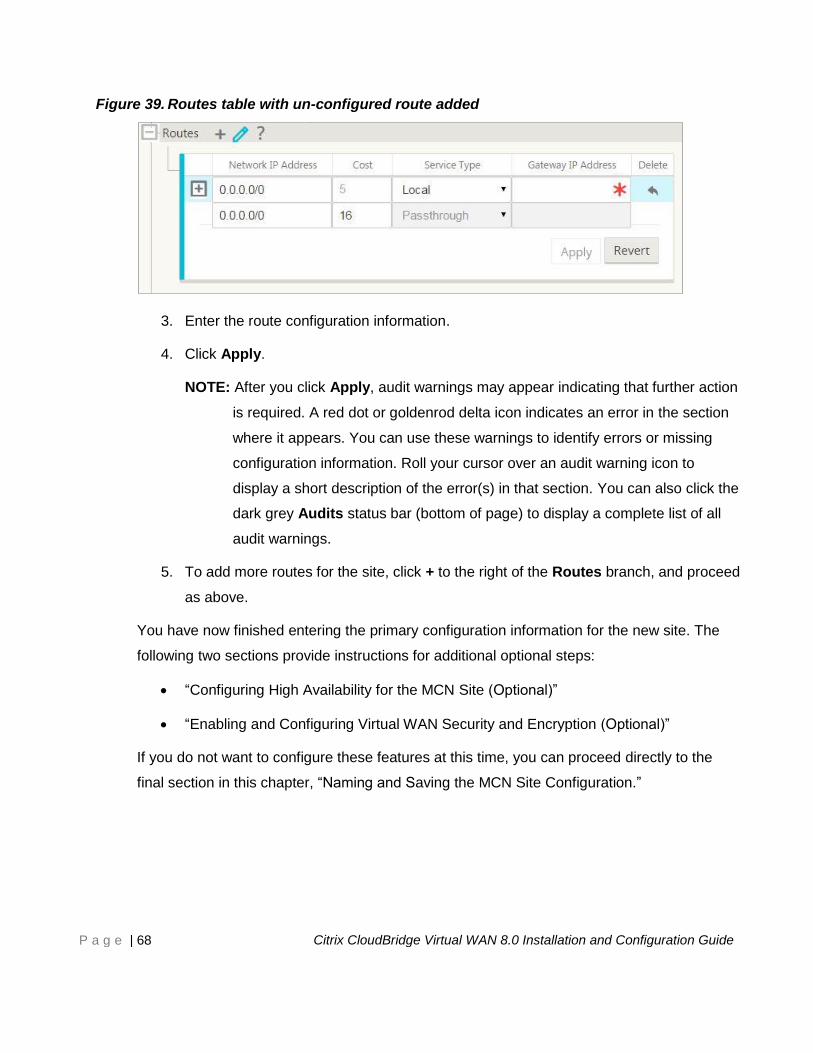
Figure 39. Routes table with un-configured route added
3. Enter the route configuration information.
4. Click Apply.
NOTE: After you click Apply, audit warnings may appear indicating that further action
is required. A red dot or goldenrod delta icon indicates an error in the section
where it appears. You can use these warnings to identify errors or missing
configuration information. Roll your cursor over an audit warning icon to
display a short description of the error(s) in that section. You can also click the
dark grey Audits status bar (bottom of page) to display a complete list of all
audit warnings.
5. To add more routes for the site, click + to the right of the Routes branch, and proceed
as above.
You have now finished entering the primary configuration information for the new site. The
following two sections provide instructions for additional optional steps:
“Configuring High Availability for the MCN Site (Optional)”
“Enabling and Configuring Virtual WAN Security and Encryption (Optional)”
If you do not want to configure these features at this time, you can proceed directly to the
final section in this chapter, “Naming and Saving the MCN Site Configuration.”
Page 69
P a g e | 69 Citrix CloudBridge Virtual WAN 8.0 Installation and Configuration Guide
Configuring High Availability for the MCN Site (Optional)
A Virtual WAN High Availability configuration is a configuration in which two Virtual WAN
Appliances at a site serve in an Active/Standby partnership, for redundancy purposes.
NOTE: Before configuring High Availability for the primary MCN site, it is best first to add
and configure the site that will act as the secondary MCN.
To configure High Availability for the MCN site, do the following:
1. Continuing in the Sites tree for the new MCN site, click + to the left of the High
Availability branch for the site.
This displays the High Availability configuration form, as shown in the following
figure.
Page 70
P a g e | 70 Citrix CloudBridge Virtual WAN 8.0 Installation and Configuration Guide
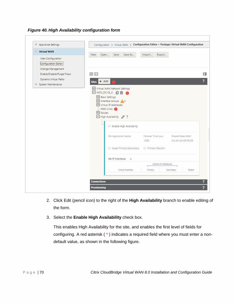
Figure 40. High Availability configuration form
2. Click Edit (pencil icon) to the right of the High Availability branch to enable editing of
the form.
3. Select the Enable High Availability check box.
This enables High Availability for the site, and enables the first level of fields for
configuring. A red asterisk ( * ) indicates a required field where you must enter a non-
default value, as shown in the following figure.
Page 71
P a g e | 71 Citrix CloudBridge Virtual WAN 8.0 Installation and Configuration Guide
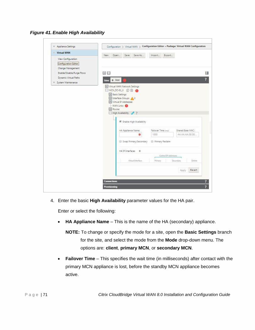
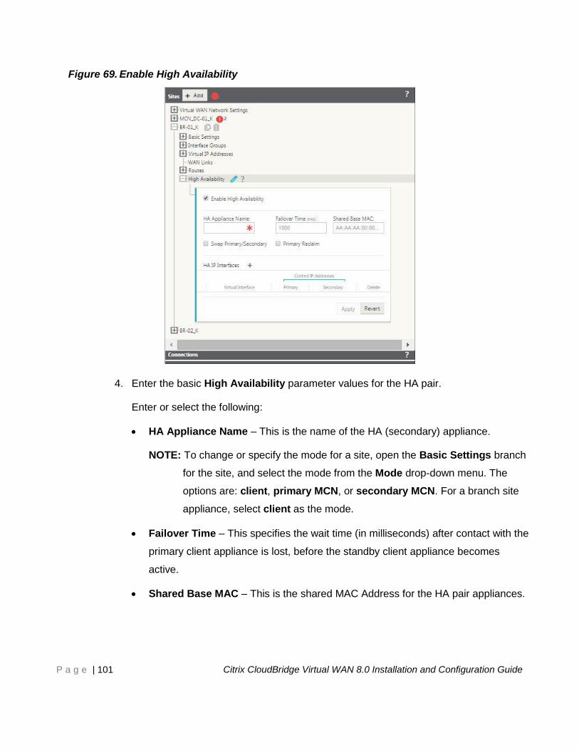
Figure 41. Enable High Availability
4. Enter the basic High Availability parameter values for the HA pair.
Enter or select the following:
HA Appliance Name – This is the name of the HA (secondary) appliance.
NOTE: To change or specify the mode for a site, open the Basic Settings branch
for the site, and select the mode from the Mode drop-down menu. The
options are: client, primary MCN, or secondary MCN.
Failover Time – This specifies the wait time (in milliseconds) after contact with the
primary MCN appliance is lost, before the standby MCN appliance becomes
active.
Page 72
P a g e | 72 Citrix CloudBridge Virtual WAN 8.0 Installation and Configuration Guide
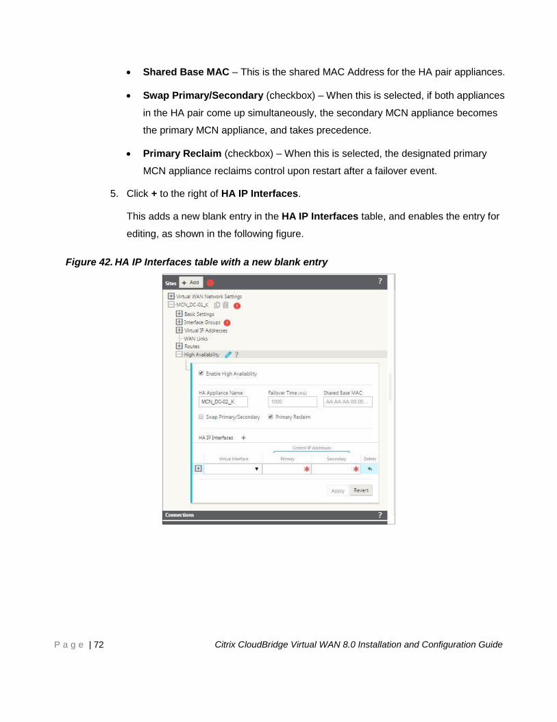
Shared Base MAC – This is the shared MAC Address for the HA pair appliances.
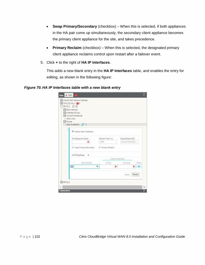
Swap Primary/Secondary (checkbox) – When this is selected, if both appliances
in the HA pair come up simultaneously, the secondary MCN appliance becomes
the primary MCN appliance, and takes precedence.
Primary Reclaim (checkbox) – When this is selected, the designated primary
MCN appliance reclaims control upon restart after a failover event.
5. Click + to the right of HA IP Interfaces.
This adds a new blank entry in the HA IP Interfaces table, and enables the entry for
editing, as shown in the following figure.
Figure 42. HA IP Interfaces table with a new blank entry
Page 73
P a g e | 73 Citrix CloudBridge Virtual WAN 8.0 Installation and Configuration Guide
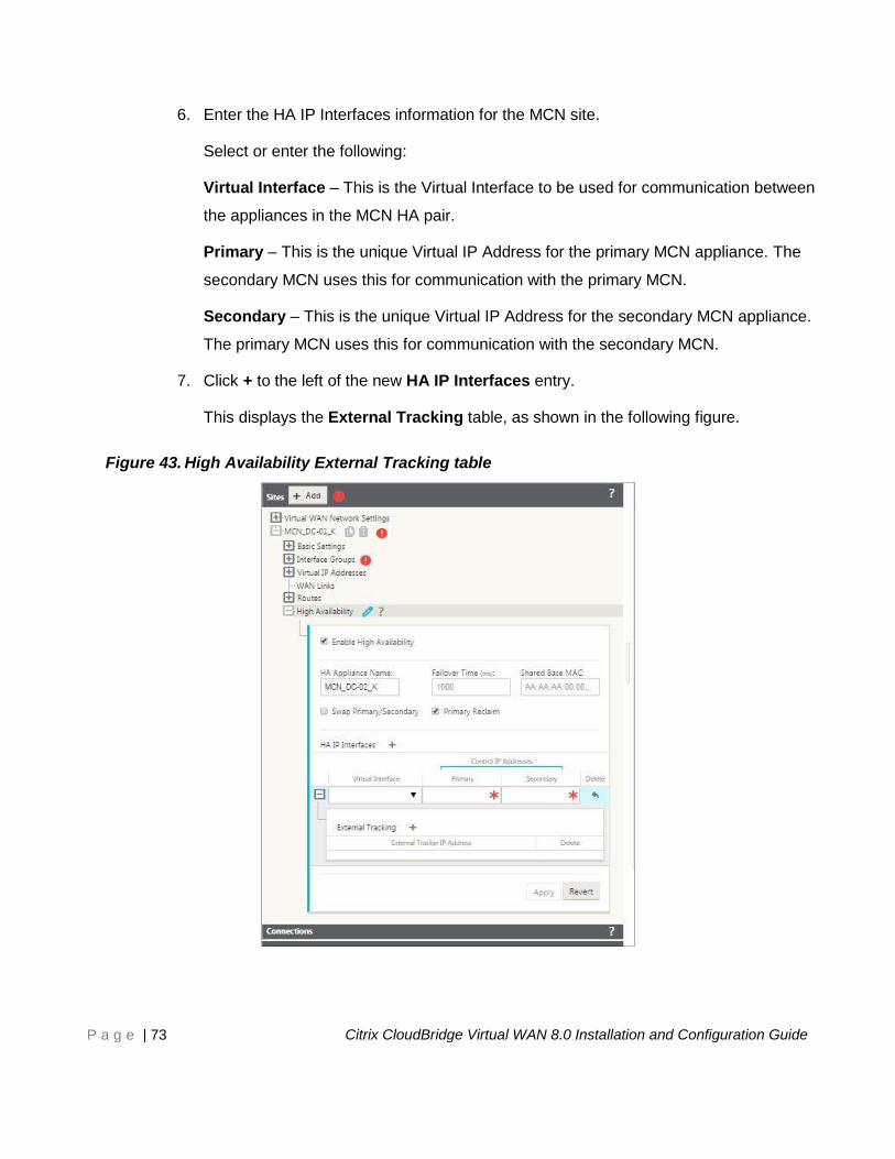
6. Enter the HA IP Interfaces information for the MCN site.
Select or enter the following:
Virtual Interface – This is the Virtual Interface to be used for communication between
the appliances in the MCN HA pair.
Primary – This is the unique Virtual IP Address for the primary MCN appliance. The
secondary MCN uses this for communication with the primary MCN.
Secondary – This is the unique Virtual IP Address for the secondary MCN appliance.
The primary MCN uses this for communication with the secondary MCN.
7. Click + to the left of the new HA IP Interfaces entry.
This displays the External Tracking table, as shown in the following figure.
Figure 43. High Availability External Tracking table
Page 74
P a g e | 74 Citrix CloudBridge Virtual WAN 8.0 Installation and Configuration Guide
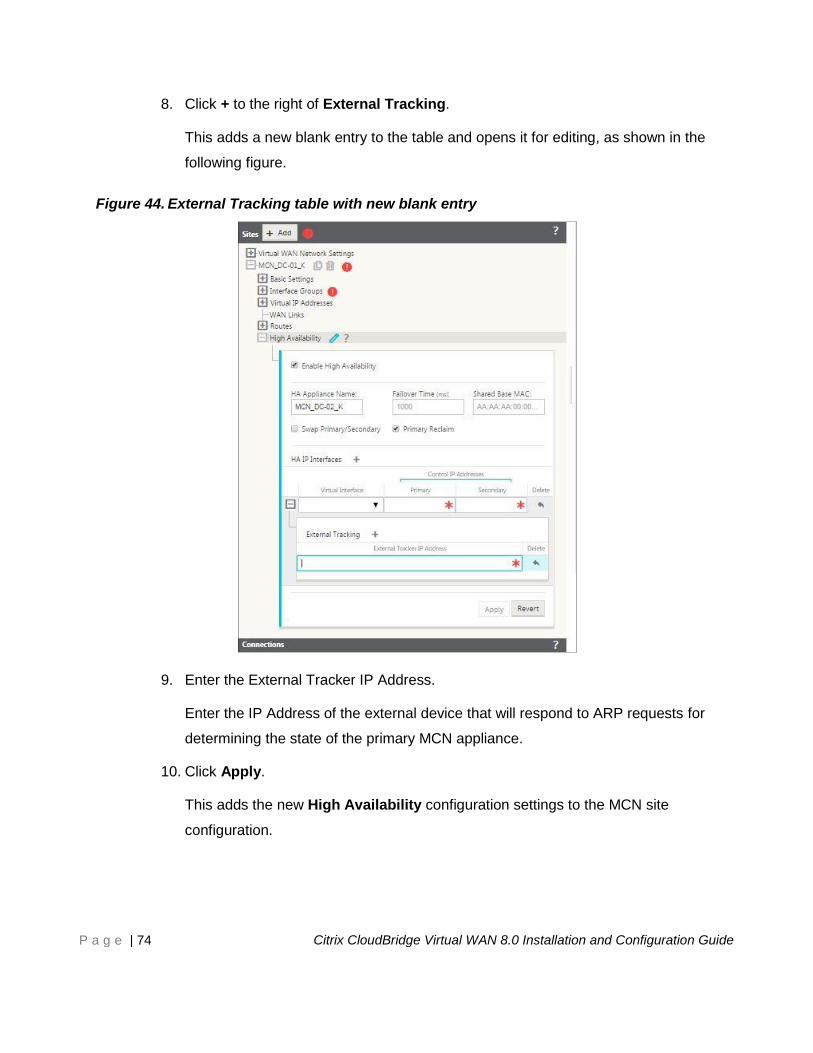
8. Click + to the right of External Tracking.
This adds a new blank entry to the table and opens it for editing, as shown in the
following figure.
Figure 44. External Tracking table with new blank entry
9. Enter the External Tracker IP Address.
Enter the IP Address of the external device that will respond to ARP requests for
determining the state of the primary MCN appliance.
10. Click Apply.
This adds the new High Availability configuration settings to the MCN site
configuration.
Page 75
P a g e | 75 Citrix CloudBridge Virtual WAN 8.0 Installation and Configuration Guide
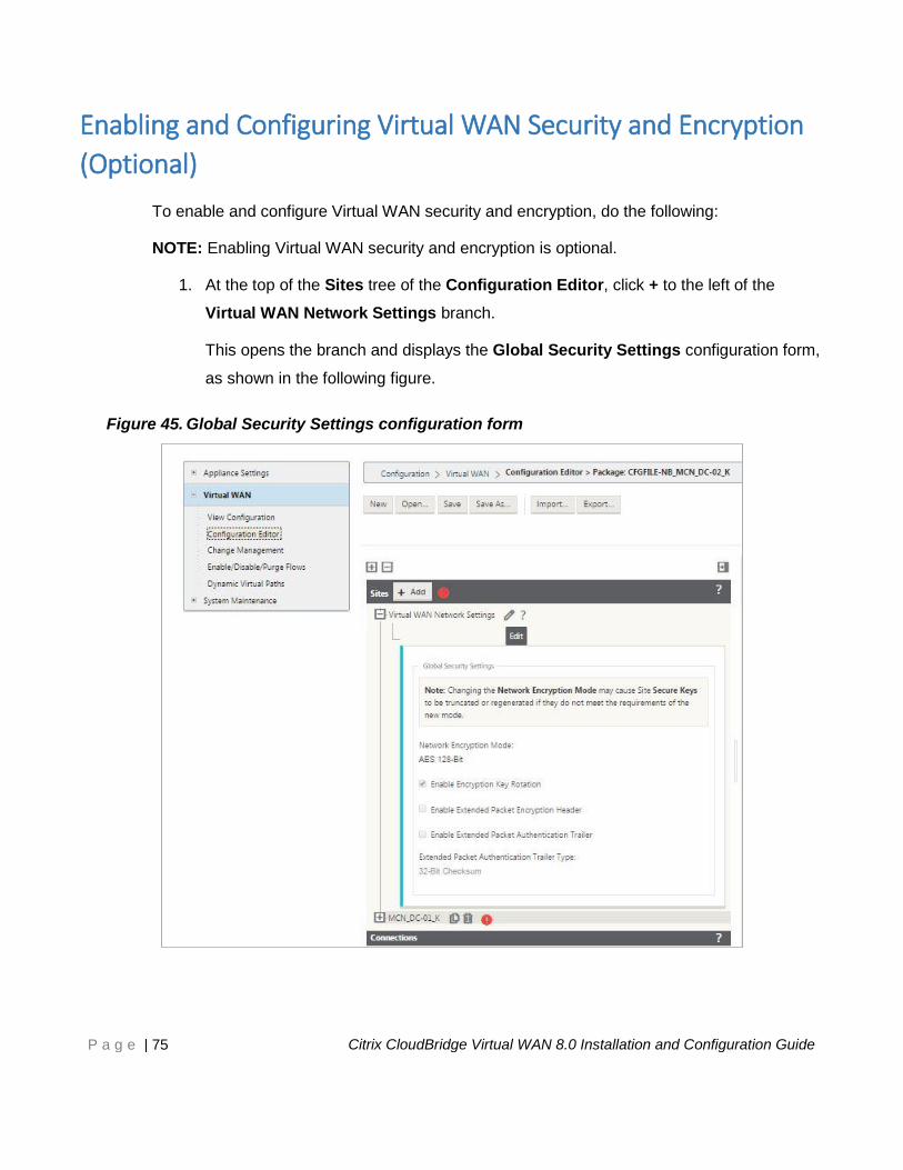
Enabling and Configuring Virtual WAN Security and Encryption
(Optional)
To enable and configure Virtual WAN security and encryption, do the following:
NOTE: Enabling Virtual WAN security and encryption is optional.
1. At the top of the Sites tree of the Configuration Editor, click + to the left of the
Virtual WAN Network Settings branch.
This opens the branch and displays the Global Security Settings configuration form,
as shown in the following figure.
Figure 45. Global Security Settings configuration form
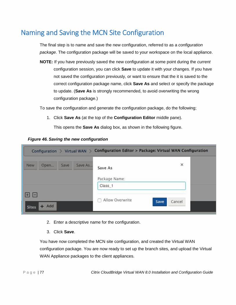
Page 76
P a g e | 76 Citrix CloudBridge Virtual WAN 8.0 Installation and Configuration Guide
2. Click Edit (pencil icon) to enable editing for the form.
3. Enter your global security settings.
The options are as follows:
Network Encryption Mode – This is the encryption algorithm used for
encrypted paths. Select one of the following from the drop-down menu: AES
128-Bit or AES 256-Bit.
Enable Encryption Key Rotation – When enabled, encryption keys are
rotated at intervals of 10 to 15 minutes.
Enable Extended Packet Encryption Header – When enabled, a 16 byte
encrypted counter is prepended to encrypted traffic to serve as an initialization
vector, and randomize packet encryption.
Enable Extended Packet Authentication Trailer – When enabled, an
authentication code is appended to the contents of the encrypted traffic to
verify that the message is delivered unaltered.
Extended Packet Authentication Trailer Type – This is the type of trailer
used to validate packet contents. Select one of the following from the drop-
down menu: 32-Bit Checksum or SHA-256.
4. Click Apply to apply your settings to the configuration.
The final step is to name and save the new MCN site configuration, as described in the
following section.
Page 77
P a g e | 77 Citrix CloudBridge Virtual WAN 8.0 Installation and Configuration Guide
Naming and Saving the MCN Site Configuration
The final step is to name and save the new configuration, referred to as a configuration
package. The configuration package will be saved to your workspace on the local appliance.
NOTE: If you have previously saved the new configuration at some point during the current
configuration session, you can click Save to update it with your changes. If you have
not saved the configuration previously, or want to ensure that the it is saved to the
correct configuration package name, click Save As and select or specify the package
to update. (Save As is strongly recommended, to avoid overwriting the wrong
configuration package.)
To save the configuration and generate the configuration package, do the following;
1. Click Save As (at the top of the Configuration Editor middle pane).
This opens the Save As dialog box, as shown in the following figure.
Figure 46. Saving the new configuration
2. Enter a descriptive name for the configuration.
3. Click Save.
You have now completed the MCN site configuration, and created the Virtual WAN
configuration package. You are now ready to set up the branch sites, and upload the Virtual
WAN Appliance packages to the client appliances.
Page 78
P a g e | 78 Citrix CloudBridge Virtual WAN 8.0 Installation and Configuration Guide
Adding and Configuring the Branch Sites This chapter provides instructions for adding and configuring the branch sites. The procedure
for adding a branch site is very similar to creating and configuring the MCN site. However,
some of the configuration steps and settings do vary slightly for a branch site. In addition,
once you have added an initial branch site, for sites that have the same appliance model, you
can use the Clone feature to streamline the process of adding and configuring those sites.
As with creating the MCN site, to set up a branch site you must use the Configuration
Editor in the Management Web Interface on the MCN appliance. The Configuration Editor
is available only when the interface is set to MCN Console mode.
The steps to complete this process are as follows:
1. Add the branch site.
2. Configure the Virtual Interface Groups for the branch site.
3. Configure the Virtual IP Addresses for the branch site.
4. Configure the WAN Links for the branch site.
5. Configure the Routes for the branch site.
6. (Optional) Configure High Availability for the branch site.
7. (Optional) Clone the new branch site to create and configure additional sites.
NOTE: Cloning the site is optional. The Virtual WAN appliance models must be the
same for both the original and the cloned sites. You cannot change the
specified appliance model for a clone. If the appliance model is different for a
site, you must manually add the site.
8. Resolve any configuration error alerts.
9. Save the completed configuration.
Page 79
P a g e | 79 Citrix CloudBridge Virtual WAN 8.0 Installation and Configuration Guide
Adding the Branch Site
To add a new branch site to the Sites table and begin configuring the site, do the following:
NOTE: If you logged out of the MCN after creating and saving the new configuration
package, you will need to log back in and reopen the configuration before you can
continue. To do so, click Open in the Configuration Editor menu bar (top of page
area). This displays a dialog box where you can select the saved configuration from a
drop-down menu. Click OK to open your selection.
1. Continuing in the Configuration Editor, click Add in the Sites bar to begin adding
and configuring the new branch site.
This displays the Add Site dialog box, as shown in the following figure.
Figure 47. Add Site dialog box
Page 80
P a g e | 80 Citrix CloudBridge Virtual WAN 8.0 Installation and Configuration Guide
2. Enter the site information, and select Client as the mode.
NOTE: Entries cannot contain spaces and must be in Linux format.
3. Click Add to add the site.
This adds the new site to the Sites tree, and opens the Basic Settings configuration
form for the site, as shown in the following figure.
Figure 48. New Client Site Basic Settings form
Page 81
P a g e | 81 Citrix CloudBridge Virtual WAN 8.0 Installation and Configuration Guide
4. Click the Edit (pencil) icon to enable editing for the form.
5. Enter the basic settings for the site, and click Apply.
This applies and saves your settings.
The next step is to add and configure the Virtual Interface Groups for the new site.
Configuring the Virtual Interface Groups for the Branch Site
After adding the new site, the next step is to create and configure the Virtual Interface Groups
for the site.
To add Virtual Interface Groups to the new site, do the following:
1. In the Sites navigation tree, click + next to the name of the site you just added.
This opens the configuration branches for the new site, as shown in the following
figure.
Figure 49. New site configuration tree
2. Click + to the left of the Interface Groups branch.
This displays the Interface Groups table for the site, as shown in the following figure.
Page 82
P a g e | 82 Citrix CloudBridge Virtual WAN 8.0 Installation and Configuration Guide
Figure 50. Interface Groups table for the new site
3. Click + to the right of Interface Groups.
This adds a new blank group entry to the table, as shown in the following figure.
Page 83
P a g e | 83 Citrix CloudBridge Virtual WAN 8.0 Installation and Configuration Guide
Figure 51. Interface Groups table with new blank entry
4. Select the Ethernet Interfaces to include.
Under Ethernet Interfaces, click a box to include/exclude that interface. A goldenrod
highlight indicates an included interface, as shown in the following figure.
Page 84
P a g e | 84 Citrix CloudBridge Virtual WAN 8.0 Installation and Configuration Guide
Figure 52. New group entry with selected Ethernet Interfaces
5. Select the Bypass Mode and Security level from the drop-down menus.
6. Click + at the left edge of the new blank entry.
This opens the entry for editing, as shown in the following figure.
NOTE: You can resize the tree pane to reveal any truncated contents. To do so, roll
your cursor over the resize bar at the right edge of the tree area. When the
cursor changes to a bi-directional arrow, click and drag the bar to the right or
left to grow or shrink the pane width.
Page 85
P a g e | 85 Citrix CloudBridge Virtual WAN 8.0 Installation and Configuration Guide
Figure 53. New group entry, opened for editing
7. Click + to the right of Virtual Interfaces.
This opens the Name and VLAN ID fields for editing, as shown in the following figure.
Page 86
P a g e | 86 Citrix CloudBridge Virtual WAN 8.0 Installation and Configuration Guide
Figure 54. Virtual Interfaces Name and VLAN ID fields
8. Enter the Name and VLAN ID for this Virtual Interface Group.
9. Click + to the right of Bridge Pairs.
This opens the Bridge Pairs fields for editing, as shown in the following figure.
Page 87
P a g e | 87 Citrix CloudBridge Virtual WAN 8.0 Installation and Configuration Guide
Figure 55. Virtual Interfaces Bridge Pairs fields open for editing
10. Select the interfaces to be paired from the drop-down menus.
To add more pairs, click + next to the Bridge Pairs field again.
11. Click Apply.
This applies your settings and adds the new Virtual Interface Group to the table, as
shown in the next figure.
Page 88
P a g e | 88 Citrix CloudBridge Virtual WAN 8.0 Installation and Configuration Guide
Figure 56. Interface Groups table with new group added, with audit warning icons
12. To add more Virtual Interface groups, click + to the right of the Interface Groups
branch, and proceed as above.
Page 89
P a g e | 89 Citrix CloudBridge Virtual WAN 8.0 Installation and Configuration Guide
Configuring the Virtual IP Addresses for the Branch Site
The next step is to configure the Virtual IP Addresses for the site, and assign them to the
appropriate group.
1. Continuing in the site tree for the new site, click + to the left of the Virtual IP
Addresses branch.
This displays the Virtual IP Addresses table for the new site, as shown in the
following figure.
Figure 57. Site Virtual IP Addresses table
Page 90
P a g e | 90 Citrix CloudBridge Virtual WAN 8.0 Installation and Configuration Guide
2. Click + to the right of the Virtual IP Addresses branch to add an address.
This opens the form for adding a new Virtual IP Address to the site configuration, as
shown in the following figure.
Figure 58. Adding a new Virtual IP Address to the site configuration
Enter the Virtual IP Address, and select the Virtual Interface group with which the
address is associated.
NOTE: You can click + again to add additional Virtual IP Addresses before
proceeding.
3. Click Apply.
This adds the address to the site and includes it in the site Virtual IP Addresses
table.
4. To add more Virtual IP Addresses, click + to the right of the Virtual IP Addresses
branch, and proceed as above.
Page 91
P a g e | 91 Citrix CloudBridge Virtual WAN 8.0 Installation and Configuration Guide
Configuring the WAN Links for the Branch Site
The next step is to configure the WAN links for the site.
1. Continuing in the site tree for the new site, click the WAN Links branch label.
This reveals the Add (+) and Help (?) active icons to the right of the WAN Links
branch, as shown in the following figure.
NOTE: At this point in a new configuration, there are no WAN links to form a table,
and therefore no Open (+) icon to the left of the WAN Links branch label.
However, if links exist, the + icon is available. If so, click + to the left of the
WAN Links branch to display the table. This also reveals the Add (+), Edit
(pencil), Delete (trashcan), and Help (?) active icons to the right of the WAN
Links branch.
Figure 59. WAN Links section with Add (+) and Help (?) active icons
2. Click + to the right of the WAN Links branch to add a new WAN link.
This opens the Add WAN Link dialog box for adding the new WAN link, as shown in
the following figure.
Page 92
P a g e | 92 Citrix CloudBridge Virtual WAN 8.0 Installation and Configuration Guide
Figure 60. Add WAN Link dialog box
3. (Optional) Enter a name for the WAN Link if you do not want to use the default.
The default name is the site name, appended with the following suffix:
-WL-<number>
Where <number> is the number of WAN Links for this site, incremented by one.
4. Select the Access Type from the drop-down menu.
The options are Public Internet or Private Intranet.
5. Click Add.
This displays the WAN Links table, adds the (not yet configured) link to the table, and
opens the Basic Settings configuration form for the link, as shown in the following
figure.
Page 93
P a g e | 93 Citrix CloudBridge Virtual WAN 8.0 Installation and Configuration Guide
Figure 61. WAN Links Basic Settings form
6. Click the Edit (pencil) icon to the right of the Settings branch to enable editing of the
form.
Page 94
P a g e | 94 Citrix CloudBridge Virtual WAN 8.0 Installation and Configuration Guide
7. Enter the path information for the new WAN link.
Some guidelines are as follows:
Some Internet links might be asymmetrical.
Misconfiguring the permitted speed can adversely affect performance for
that path.
Avoid using burst speeds that surpass the Committed Rate.
For Internet WAN link paths, be sure to add the Public IP Address.
8. Click the Advanced Settings section bar.
This opens the Advanced Settings form for the link, as shown in the following figure.
Figure 62. WAN Link Advanced Settings form
Page 95
P a g e | 95 Citrix CloudBridge Virtual WAN 8.0 Installation and Configuration Guide
9. Enter the Advanced Settings for the link.
10. Click the Eligibility section bar.
This opens the Eligibility settings form for the link, as shown in the next figure.
Figure 63. WAN Links Eligibility settings form
11. Select the Eligibility settings for the link.
12. Click Apply.
Page 96
P a g e | 96 Citrix CloudBridge Virtual WAN 8.0 Installation and Configuration Guide
13. Click + next to the Access Interfaces branch in the configuration tree for the link.
This opens the Access Interfaces table for the site, as shown in the following figure.
Figure 64. Access Interfaces table
14. Click + to the right of the Access Interfaces branch to add an interface.
This adds a blank entry to the table and opens it for editing, as shown in the next
figure.
Figure 65. New Access Interfaces entry opened for editing
Page 97
P a g e | 97 Citrix CloudBridge Virtual WAN 8.0 Installation and Configuration Guide
15. Enter the Access Interfaces settings for the link
16. Click Apply.
You have now finished configuring the new WAN link. Repeat these steps to add and
configure additional WAN links for the site.
The next step is to add and configure the routes for the site.
Configuring the Routes for the Branch Site
To add and configure the routes for the site, do the following:
1. Continuing in the site tree for the new site, click + to the left of the Routes branch.
This displays the Routes table for the site, as shown in the following figure.
Figure 66. Site Routes table
2. Click + to the right of the Routes branch to add a route.
This opens the Routes table for editing and adds a blank route entry to the table, as
shown in the following figure.
Page 98
P a g e | 98 Citrix CloudBridge Virtual WAN 8.0 Installation and Configuration Guide
Figure 67. Routes table with un-configured route added
3. Enter the route configuration information and click Apply.
NOTE: After you click Apply, audit warnings may appear indicating that further action
is required. A red dot or goldenrod delta icon indicates an error in the section
where it appears. You can use these warnings to identify errors or missing
configuration information. Roll your cursor over an audit warning icon to
display a short description of the error(s) in that section. You can also click the
dark grey Audits status bar (bottom of page) to display a complete list of all
audit warnings.
4. To add more routes for the site, click + to the right of the Routes branch, and proceed
as above.
5. (Recommended.) Save your changes to the configuration.
If you have previously saved the new configuration package at some point during the
current configuration session, you can click Save to update the current package with
your changes. If you have not saved the configuration previously, or want to ensure
that it is saved to the correct package name, click Save As and select or specify the
package to update. (Save As is strongly recommended, to avoid overwriting the
wrong configuration package.)
Page 99
P a g e | 99 Citrix CloudBridge Virtual WAN 8.0 Installation and Configuration Guide
The following two sections provide instructions for the following optional steps:
“Configuring High Availability (HA) for the Branch Site (Optional)” – High Availability
refers to a configuration in which two Virtual WAN Appliances at a site serve in an
Active/Standby partnership capacity for redundancy purposes. If you are not
implementing High Availability for this site, you can skip this step.
“Cloning the Branch Site (Optional)” – You have the option of cloning the branch site
you just configured, if the appliance models for the original site and the clone are the
same. You can then use the clone as a template to streamline the process of adding
and configuring additional branch sites.
Page 100
P a g e | 100 Citrix CloudBridge Virtual WAN 8.0 Installation and Configuration Guide
Configuring High Availability (HA) for the Branch Site (Optional)
To configure High Availability for the branch site, do the following:
1. Continuing in the Sites tree, click + to the left of the High Availability branch for the
new site.
This displays the High Availability configuration form, as shown in the following
figure.
Figure 68. High Availability configuration form
2. Click Edit (pencil icon) to the right of the High Availability branch to enable editing of
the form.
3. Select the Enable High Availability check box.
This enables High Availability for the site, and enables the first level of fields for
configuring. A red asterisk ( * ) indicates a required field where you must enter a non-
default value, as shown in the following figure.
Page 101
P a g e | 101 Citrix CloudBridge Virtual WAN 8.0 Installation and Configuration Guide
Figure 69. Enable High Availability
4. Enter the basic High Availability parameter values for the HA pair.
Enter or select the following:
HA Appliance Name – This is the name of the HA (secondary) appliance.
NOTE: To change or specify the mode for a site, open the Basic Settings branch
for the site, and select the mode from the Mode drop-down menu. The
options are: client, primary MCN, or secondary MCN. For a branch site
appliance, select client as the mode.
Failover Time – This specifies the wait time (in milliseconds) after contact with the
primary client appliance is lost, before the standby client appliance becomes
active.
Shared Base MAC – This is the shared MAC Address for the HA pair appliances.
Page 102
P a g e | 102 Citrix CloudBridge Virtual WAN 8.0 Installation and Configuration Guide
Swap Primary/Secondary (checkbox) – When this is selected, if both appliances
in the HA pair come up simultaneously, the secondary client appliance becomes
the primary client appliance for the site, and takes precedence.
Primary Reclaim (checkbox) – When this is selected, the designated primary
client appliance reclaims control upon restart after a failover event.
5. Click + to the right of HA IP Interfaces.
This adds a new blank entry in the HA IP Interfaces table, and enables the entry for
editing, as shown in the following figure:
Figure 70. HA IP Interfaces table with a new blank entry
Page 103
P a g e | 103 Citrix CloudBridge Virtual WAN 8.0 Installation and Configuration Guide
6. Enter the HA IP Interfaces information for the branch site.
Select or enter the following:
Virtual Interface – This is the Virtual Interface to be used for communication between
the appliances in the HA appliance pair.
Primary – This is the unique Virtual IP Address for the primary client appliance for
this site. The secondary appliance uses this for communication with the primary client
appliance.
Secondary – This is the unique Virtual IP Address for the secondary client appliance
for this site. The primary appliance uses this for communication with the secondary
client appliance.
7. Click + to the left of the new HA IP Interfaces entry.
This displays the External Tracking table, as shown in the following figure.
Page 104
P a g e | 104 Citrix CloudBridge Virtual WAN 8.0 Installation and Configuration Guide
Figure 71. High Availability External Tracking table
8. Click + to the right of External Tracking.
This adds a new blank entry to the table and opens it for editing, as shown in the
following figure.
Page 105
P a g e | 105 Citrix CloudBridge Virtual WAN 8.0 Installation and Configuration Guide
Figure 72. External Tracking table with new blank entry
9. Enter the External Tracker IP Address.
Enter the IP Address of the external device that will respond to ARP requests for
determining the state of the primary client appliance.
10. Click Apply.
This adds the new High Availability configuration settings to the branch site
configuration.
Page 106
P a g e | 106 Citrix CloudBridge Virtual WAN 8.0 Installation and Configuration Guide
Cloning the Branch Site (Optional)
This section provides instructions for cloning the branch site you just configured to use as a
partial template for adding more branch sites.
NOTE: Cloning the site is optional. The Virtual WAN appliance models must be the same for
both the original and the cloned sites. You cannot change the specified appliance
model for a clone. If the appliance model is different for a site, you must manually add
the site, as instructed in the previous sections.
Cloning a site streamlines the process of adding and configuring additional branch nodes.
When a site is cloned, the entire set of configuration settings for the site are copied and
displayed in a single form page. You can then modify the settings according to the
requirements of the new site. Some of the original settings can be retained, where applicable.
However, most of the settings must be unique for each site.
To clone a site, do the following:
1. In the Sites tree (middle pane) of the Configuration Editor, click + to the left of the
branch site you want to duplicate.
This opens that site branch in the Sites tree, and reveals the Clone (double page
icon) and Delete (trashcan icon) buttons, as shown in the following figure.
Figure 73. Clone site button
Page 107
P a g e | 107 Citrix CloudBridge Virtual WAN 8.0 Installation and Configuration Guide
2. Click the Clone icon to the right of the branch site name in the tree.
This opens the Clone Site configuration page, as shown in the following figure.
Figure 74. Clone Site configuration page
3. Enter the configuration parameter settings for the new site.
A pink field with an alert icon (red dot) indicates a required parameter setting that
must have a value different than the setting for the original cloned site. In most cases,
this value must be unique.
TIP: To further streamline the cloning process, use a consistent, pre-defined naming
convention when naming the clones.
4. Resolve any error alerts.
To diagnose an error, roll your cursor over the Alert icon (red dot or goldenrod delta)
to reveal bubble help for that specific error.
Page 108
P a g e | 108 Citrix CloudBridge Virtual WAN 8.0 Installation and Configuration Guide
5. Click Clone (far right corner) to create the new site and add it to the Sites table.
NOTE: The Clone button remains unavailable until you have entered all of the
required values, and the new site configuration is error-free.
6. (Optional.) Save your changes to the configuration.
If you have previously saved the new configuration package at some point during the
current configuration session, you can click Save to update the current package with
your changes. If you have not saved the configuration previously, or want to ensure
that it is saved to the correct package name, click Save As and select or specify the
package to update. (Save As is strongly recommended, to avoid overwriting the
wrong configuration package.)
You have now finished configuring the branch sites. The next step is to check the
configuration for error alerts, and make corrections or additions as needed.
Page 109
P a g e | 109 Citrix CloudBridge Virtual WAN 8.0 Installation and Configuration Guide
Resolving Configuration Error Alerts
An Alert icon (a red dot or goldenrod delta) next to an item indicates a configuration error or
missing parameter information for that item. A number next to the icon indicates the number
of associated errors for that alert. To see bubble help for a particular alert, roll your cursor
over the Alert icon. This displays a brief description of the specific errors flagged by that Alert.
For additional information and instructions on diagnosing and resolving configuration errors,
please refer to the Citrix CloudBridge Virtual WAN Planning Guide and Citrix CloudBridge
Virtual WAN Administration Guide.
Saving the Completed Configuration
The next step is to save the completed configuration package. The file will be saved to your
workspace on the local appliance.
NOTE: If you have previously saved the new configuration at some point during the current
configuration session, you can click Save to update the current package with your
changes. If you have not saved the configuration previously, or want to ensure that it
is saved to the correct package name, click Save As and select or specify the
package to update. (Save As is strongly recommended, to avoid overwriting the
wrong configuration package.) If you have not previously saved the configuration
package, please follow the instructions below.
To save the configuration and generate or update the configuration package, do the
following;
1. Click Save As (at the top of the Configuration Editor middle pane).
This opens the Save As dialog box, as shown in the following figure.
Page 110
P a g e | 110 Citrix CloudBridge Virtual WAN 8.0 Installation and Configuration Guide
Figure 75. Saving the completed configuration package
2. Enter a descriptive name for the configuration.
3. Click Save.
Exporting the Configuration Package
The final step is to export the completed configuration package to the Management Web
Interface Change Management system, in preparation for uploading the configuration to the
MCN and client appliances. You can also use the Export feature to download a copy of the
configuration package to the local PC.
To export the configuration package to Change Management, do the following:
1. In the Configuration Editor page, click Export (at the top of the page).
The following figure shows the location of the Export button.
Page 111
P a g e | 111 Citrix CloudBridge Virtual WAN 8.0 Installation and Configuration Guide
Figure 76. Configuration Editor Export button
This opens the Export Configuration dialog box, as shown in the following figure.
Figure 77. Export Configuration dialog box
Page 112
P a g e | 112 Citrix CloudBridge Virtual WAN 8.0 Installation and Configuration Guide
2. Select Change Management Inbox as the export destination.
Use the drop-down menu in the Destination: field to make your selection.
3. Click Export.
When the export operation completes, a green success status message displays at
the top of the page, as shown in the following figure.
Figure 78. Export success status message
TIP: You can click the blue Change Management link in the success message to go
directly to the Change Preparation -- Upload and Verify Files page (second
page) of the Change Management wizard. You will need to navigate to this
page to perform the next step in the configuration process. However, the
success message displays for only a few seconds, after which you must use the
navigation tree to open the wizard and then step through to this page.
Instructions are provided in the next chapter.
You are now ready to upload the CloudBridge Virtual WAN software package to the MCN
Appliance.
Page 113
P a g e | 113 Citrix CloudBridge Virtual WAN 8.0 Installation and Configuration Guide
Preparing the Virtual WAN Appliance Packages
on the MCN The next step is to prepare the Virtual WAN Appliance packages, by means of the Change
Management wizard on the MCN.
There is a different Virtual WAN software version for each Virtual WAN Appliance model. An
Appliance Package consists of the software version for a given model, bundled with the
configuration package you want to deploy. Consequently, a different Appliance Package must
be prepared and generated for each appliance model in your network.
NOTE: If you have not already downloaded the required CloudBridge Virtual WAN software
versions to a PC connected to your network, you will need to do so now. For
information on acquiring and downloading the software, see the section entitled,
“CloudBridge Virtual WAN Software Requirements” in “Chapter 3: Before You Begin.”
To upload and install the package and configuration to the MCN, do the following:
1. If you have not already done so, log into the Management Web Interface on the MCN
appliance.
NOTE: You will be uploading the software packages you previously downloaded to
the connected PC. For convenience, you might want to use this same PC to
connect to the MCN again, now.
2. Select the Configuration tab.
3. In the left pane, open the Virtual WAN section, and select Change Management.
This displays the first page of the Change Management wizard, the Change
Process Overview page, as shown in the following figure.
Page 114
P a g e | 114 Citrix CloudBridge Virtual WAN 8.0 Installation and Configuration Guide
Figure 79. Change Management wizard – Change Process Overview page.
4. Click Begin.
This displays the Change Preparation page for uploading and verifying the appliance
software version and configuration, as shown in the following figure.
Page 115
P a g e | 115 Citrix CloudBridge Virtual WAN 8.0 Installation and Configuration Guide
Figure 80. Change Management wizard – Change Preparation page.
5. Upload each of the Virtual WAN software versions required for your network.
NOTE: Before proceeding with this step, make sure you have downloaded a copy of
the appropriate Virtual WAN software version for each of the different
appliance models in your network. For information on downloading the
software packages, see the section entitled, “CloudBridge Virtual WAN
Software Requirements” in “Chapter 3: Before You Begin.”
For each Virtual WAN software version you want to deploy, do the following:
a) Click Choose File next to the Upload Item field.
This opens a file browser for selecting the Virtual WAN software package you
want to upload.
b) Select a Virtual WAN software package, and click OK.
Navigate to the CloudBridge Virtual WAN software packages you
downloaded earlier to the local PC, and select a package to upload.
Page 116
P a g e | 116 Citrix CloudBridge Virtual WAN 8.0 Installation and Configuration Guide
c) Click Upload.
d) Repeat steps (a) through (c) for each of the Virtual WAN software versions
required for your network.
6. In the Configuration field drop-down menu, select the new configuration package
that you just exported to Change Management.
7. Click Next.
The selected file is submitted for verification, and the Verification results page
displays, as shown in the following figure.
Figure 81. Change Management wizard – Verification Results page.
8. Click OK.
This dismisses the Verification page and proceeds to Appliance Staging page, as
shown in the following figure.
Page 117
P a g e | 117 Citrix CloudBridge Virtual WAN 8.0 Installation and Configuration Guide
Figure 82. Change Management wizard – Appliance Staging page.
9. Check the Ignore Incomplete box.
This indicates that the client sites should be ignored for this staging operation, and
only the MCN should be updated and staged at this time.
NOTE: In the future, if you need to update this configuration after it has been
deployed and Virtual Path communication is in effect, you can skip this step. In
such a case, the configuration will be automatically distributed from the MCN
to all active remotes through the existing Virtual Path.
10. Click Stage Appliances.
This transfers the selected appliance software version and configuration to the MCN,
and initiates staging of the MCN. A Transfer Progress status bar displays as the
transfer proceeds, as shown in the following figure.
Page 118
P a g e | 118 Citrix CloudBridge Virtual WAN 8.0 Installation and Configuration Guide
Figure 83. Appliance Staging Transfer Progress status bar
11. Click Next to proceed to the Activation tab Activate page.
12. Click Activate Staged.
This activates the software package and the new configuration on the appliance.
This may take several seconds to complete.
When the activation completes, a status message displays stating Activation
complete, and the Done button becomes available. In addition, the Configuration
Filenames status line (above the table) now displays the name of newly-activated
package in the Active field.
13. Click Done to exit the wizard and view the activation results.
After the CloudBridge Virtual Path Service starts on the appliance, click Done on the
Activation page to return to the Management Web Interface Dashboard page. This
page now displays updated information regarding the software build, the status of the
newly-activated appliance, and the status of the CloudBridge Virtual Path.
You have now successfully uploaded and installed the CloudBridge Virtual WAN software on
the MCN. The next step is for the branch Site Administrators to connect the client appliances
to your network at their respective branch sites.
Page 119
P a g e | 119 Citrix CloudBridge Virtual WAN 8.0 Installation and Configuration Guide
Connecting the Client Appliances to Your
Network The next step is for the branch Site Administrators to connect the client appliances to the
network at their respective branch sites. This is in preparation for uploading and activating the
appropriate CloudBridge Virtual WAN software version and configuration package to the
clients. You will need to contact each branch Site Administrator to initiate and coordinate
these procedures.
To connect your appliance, do the following:
1. Connect the appliance to the branch site LAN.
Connect one end of an Ethernet cable to a port configured for LAN on the
CloudBridge Virtual WAN Appliance, and the other end of the cable to the LAN switch.
2. Connect the appliance to the WAN.
Connect one end of an Ethernet cable to a port configured for WAN on the
CloudBridge Virtual WAN Appliance, and the other end of the cable to the WAN
router.
The next step is for the branch Site Administrators to install and activate the appropriate
CloudBridge Virtual WAN Appliance Package on their clients.
Page 120
P a g e | 120 Citrix CloudBridge Virtual WAN 8.0 Installation and Configuration Guide
Installing the Virtual WAN Appliance Packages on
the Clients After you have prepared and connected the MCN, and the branch Site Administrators have
connected their respective client appliances to the LAN and WAN, the next step is to upload
and activate the appropriate CloudBridge Virtual WAN Appliance package on each client. The
Change Management wizard guides you through this process.
To install and activate the software and configuration on a client appliance, do the following:
1. On a connected PC, open a browser and log onto the MCN appliance Management
Web Interface.
Enter the Management IP Address for the MCN in the browser address field. This
displays the Management Web Interface Dashboard page for the MCN appliance.
2. Select the Configuration tab.
3. Select Virtual WAN and then select Change Management in the navigation pane on
the left.
This displays the Change Process Overview page (the first page of the Change
Management wizard), as shown in the following figure.
Page 121
P a g e | 121 Citrix CloudBridge Virtual WAN 8.0 Installation and Configuration Guide
Figure 84. Change Management wizard – Change Process Overview page
At the bottom of this page, you will see a table listing the individual sites and
appliances. At the far right of the table in the Download Package column, are links
for the active and staged Appliance Packages.
4. Click the Active link for the package you want to download.
In the Site-Appliance table, locate the entry for your site appliance, and click the
Active link in the Download Package column of that entry. A file browser for
selecting the download location (on the local PC) displays.
5. Select the download location and click OK.
6. (Optional.) After the download completes, log out of the MCN Management Web
Interface.
7. Open a browser, and enter the IP Address for the client to which you want to upload
the Appliance Package Zip file.
Page 122
P a g e | 122 Citrix CloudBridge Virtual WAN 8.0 Installation and Configuration Guide
NOTE: Please ignore any browser certificate warnings for the CloudBridge
Management Web Interface.
This opens the CloudBridge Management Web Interface Login screen on the client
appliance, as shown in the following figure.
Figure 85. Citrix CloudBridge Management Web Interface Login Screen
8. Enter the Administrator user name and password and click Login.
The default Administrator user name is admin; the default password is password.
This displays the Management Web Interface Dashboard page for the client
appliance, as shown in the next figure.
Page 123
P a g e | 123 Citrix CloudBridge Virtual WAN 8.0 Installation and Configuration Guide
Figure 86. Client Dashboard
9. Select the Configuration tab.
10. Open the System Maintenance branch in the navigation tree (left pane), and select
Local Change Management.
This displays the Local Appliance Change Process Upload page for uploading and
verifying the client software and configuration, as shown in the following figure.
Page 124
P a g e | 124 Citrix CloudBridge Virtual WAN 8.0 Installation and Configuration Guide
Figure 87. Local Change Management – Local Appliance Change Process Upload page.
11. Click Choose File next to the Upload Item field.
This opens a file browser for selecting the file you want to upload to the client.
12. Navigate to the CloudBridge Virtual WAN software package Zip file you just
downloaded from the MCN, select it, and click OK.
13. Click Upload.
The upload process takes a few seconds to complete. When completed, a status
message displays (left middle of page), stating Upload complete, as shown in the
following figure.
Page 125
P a g e | 125 Citrix CloudBridge Virtual WAN 8.0 Installation and Configuration Guide
Figure 88. Upload complete status message
14. Click Next.
This uploads the specified software package, and displays the Local Change
Management Activation page, as shown in the following figure.
Figure 89. Change Management wizard – Activation page
Page 126
P a g e | 126 Citrix CloudBridge Virtual WAN 8.0 Installation and Configuration Guide
15. Click Activate Staged.
This activates the newly-installed package and starts the CloudBridge Virtual Path
Service on the client appliance. This process takes several seconds, during which a
progress status message displays, as shown in the following figure.
Figure 90. Activation status message
When the activation completes, a status message displays stating Activation
complete, and the Done button becomes available.
16. Click Done to exit the wizard and view the activation results.
After the CloudBridge Virtual Path Service starts on the appliance, click Done on the
Activation page to return to the Management Web Interface Dashboard page. This
page should now display updated information regarding the software build, the status
of the newly-activated client appliance, and the status of the CloudBridge Virtual Path.
The following figure shows a sample client Dashboard page.
Page 127
P a g e | 127 Citrix CloudBridge Virtual WAN 8.0 Installation and Configuration Guide
Figure 91. Sample client Dashboard page
This completes the installation and activation of the CloudBridge Virtual WAN software and
configuration on the MCN and branch site client appliances. You can now use the
Monitoring pages to verify the activation and diagnose any existing or potential configuration
issues. Basic instructions are provided in the next chapter.
Page 128
P a g e | 128 Citrix CloudBridge Virtual WAN 8.0 Installation and Configuration Guide
Monitoring Your CloudBridge Virtual WAN This chapter provides basic instructions for using the Management Web Interface to monitor
your CloudBridge Virtual WAN.
For additional information about CloudBridge Virtual WAN statistics and statistical reports,
please see the CloudBridge Virtual WAN Administration Guide.
Viewing Basic Information for an Appliance
Use a browser to connect to the Management Web Interface of the appliance you want to
monitor, and click the Dashboard tab to display basic information for that appliance.
The Dashboard page displays the following basic information for the local appliance:
System Status:
Name – This is the name you assigned to the appliance when you added it to the system.
Model – This is the Virtual WAN appliance model number.
Appliance Mode – This indicates whether this appliance has been configured as the
primary or secondary MCN, or as a client appliance.
Management IP Address – This is the Management IP Address for the appliance.
Appliance Uptime – This specifies the duration for which the appliance has been running
since the last reboot.
Service Uptime – This specifies the duration for which the Virtual WAN Service has been
running since the last restart.
Page 129
P a g e | 129 Citrix CloudBridge Virtual WAN 8.0 Installation and Configuration Guide
Virtual Path Service Status:
Virtual Path [path name] – This identifies the Virtual Path for this Virtual Path
Service.
Local Version Information:
Software version – This is the version of the CloudBridge Virtual Path software
package currently activated on the appliance.
Build date – This is the build date for the product version currently running on the
local appliance.
Hardware version – This is the hardware model number and version of the
appliance.
The following figure shows a sample Dashboard page for the MCN, and MCN Appliance
information.
Figure 92. Example Dashboard page for the MCN Appliance
Page 130
P a g e | 130 Citrix CloudBridge Virtual WAN 8.0 Installation and Configuration Guide
The following figure shows a sample Dashboard page and information for a client appliance.
Figure 93. Client Dashboard page
Viewing Path Statistics
To view state and related information about the CloudBridge Virtual Paths for both the MCN
and the clients, do the following:
1. Log onto the Management Web Interface for the MCN, and select the Monitoring tab.
2. Open the Virtual WAN branch in the navigation tree (left pane).
3. Select the Statistics branch under Virtual WAN.
This displays the Statistics page with Paths preselected in the Show field, which
displays a detailed table of path statistics, as shown in the following figure.
Page 131
P a g e | 131 Citrix CloudBridge Virtual WAN 8.0 Installation and Configuration Guide
Figure 94. Virtual WAN Path Statistics page
Viewing Other Statistical Information and Reports
This section provides some rudimentary instructions on viewing CloudBridge Virtual WAN
statistics and reports information.
Viewing Other Statistical Information
This section provides basic instructions for viewing Virtual WAN Statistics information.
To view statistical information, do the following:
1. Log onto the Management Web Interface for the MCN, and select the Monitoring tab.
2. Open the Virtual WAN branch in the navigation tree (left pane).
3. Select the Statistics branch under Virtual WAN.
This displays the Statistics page with Paths preselected by default in the Show field.
Page 132
P a g e | 132 Citrix CloudBridge Virtual WAN 8.0 Installation and Configuration Guide
4. Open the Show drop-down menu next to the Show field.
In addition to the Paths statistics, the Show menu also offers several additional
options for viewing statistical information, as illustrated in the following figure.
Figure 95. Virtual WAN Statistics Show menu
5. Select a topic from the Show menu to view a table of statistical information for
that topic.
Viewing Flow Information
This section provides basic instructions for viewing Virtual WAN flow information.
To view flow information, do the following:
1. Log onto the Management Web Interface for the MCN, and select the Monitoring tab.
2. Open the Virtual WAN branch in the navigation tree (left pane).
Page 133
P a g e | 133 Citrix CloudBridge Virtual WAN 8.0 Installation and Configuration Guide
3. Select the Flows branch under Virtual WAN.
This displays the Flows page with LAN to WAN preselected in the Flow Type field,
as shown in the following figure.
Figure 96. Virtual WAN Flows page
4. Select the Flow Type.
Next to the Flow Type field is a row of checkbox options for selecting the flow
information you want to view. You can check one or more boxes to filter the
information to be displayed.
5. Select the Max Flows to Display from the drop-down menu next to that field.
6. (Optional) Enter search text in the Filter field.
7. Click Refresh to display the results.
Page 134
P a g e | 134 Citrix CloudBridge Virtual WAN 8.0 Installation and Configuration Guide
Viewing Reports
This section provides basic instructions for generating and viewing CloudBridge Virtual WAN
reports using the MCN Management Web Interface. You can also generate reports using a
client Management Web Interface, but the scope of those reports in some cases will be
limited to the local branch.
To generate and view CloudBridge Virtual WAN reports, do the following:
1. Log onto the Management Web Interface for the MCN, and select the Monitoring tab.
2. Open the Virtual WAN branch in the navigation tree (left pane).
The Virtual WAN branch offers the following options for viewing reports:
Performance Reports
QoS Reports
Usage Reports
Availability Reports
Appliance Reports
3. Select the option for the type of report you want to view.
NOTE: For each type of report, there are numerous options for defining and filtering
the information you want to view. For a complete description of Virtual WAN
reports and monitoring, please refer to the CloudBridge Virtual WAN
Administration Guide.
Page 135
P a g e | 135 Citrix CloudBridge Virtual WAN 8.0 Installation and Configuration Guide
Appendix A
Standard MIB Support The following standard MIBs are supported by the Virtual WAN Appliances.
MIB RFC DEFINITION (LINK)
DISMAN-EVENT-MIB https://www.ietf.org/rfc/rfc2981.txt
HOST-RESOURCES-MIB https://www.ietf.org/rfc/rfc2790.txt
IF-MIB https://www.ietf.org/rfc/rfc2863.txt
IP-FORWARD-MIB https://www.ietf.org/rfc/rfc4292.txt
IP-MIB (Partial) https://www.ietf.org/rfc/rfc4293.txt
Q-BRIDGE-MIB (Partial) http://www.ieee802.org/1/files/public/MIBs/IEEE8021-Q-
BRIDGE-MIB-201112120000Z.txt
RFC1213-MIB https://www.ietf.org/rfc/rfc1213.txt
SNMPv2-MIB https://www.ietf.org/rfc/rfc3418.txt
TCP-MIB https://www.ietf.org/rfc/rfc4022.txt
P-BRIDGE-MIB.txt http://www.icir.org/fenner/mibs/extracted/P-BRIDGE-
MIB-rfc2674.txt
RMON2-MIB.txt https://www.ietf.org/rfc/rfc3273.txt
TOKEN-RING-RMON-MIB.txt http://www.icir.org/fenner/mibs/extracted/TOKEN-RING-
RMON-MIB-rmonmib-01.txt
Page 136
P a g e | 136 Citrix CloudBridge Virtual WAN 8.0 Installation and Configuration Guide
Additional Notes
Support for these MIBs is provided by default by the net-snmp snmpd daemon
process on Linux systems. The MIBs provide the basis for supporting Network
Management applications, for example: Nagios or SolarWinds.
The Ethernet port packet and byte counters are in the IF-MIB inside the ifTable.
System information is in the system object.
Ethernet ports are included in the ifTable, so walking that should be sufficient to
ensure that the SNMP subsystem is running.
Support for the Q-BRIDGE-MIB and the IP-MIB provides support for the network
mapping application in SolarWinds.
Page 137
P a g e | 137 Citrix CloudBridge Virtual WAN 8.0 Installation and Configuration Guide
Glossary The following table provides basic definitions of the key CloudBridge Virtual WAN terms and concepts.
TERM DEFINITION
Access Interface An Access Interface consists of a Virtual Interface, WAN endpoint IP Address, Gateway IP Address, and Virtual Path Mode defined collectively as an interface for a specific WAN link. Each WAN link must have at least one Access Interface.
branch node A branch node is a Virtual WAN Appliance that is deployed as a Virtual WAN client at an Enterprise branch (remote) site, and across the Virtual WAN from the associated Master Control Node (MCN). An MCN can be associated with multiple Virtual WAN branch nodes; however, each Virtual WAN branch node can be associated with only one MCN. (See also: client node.)
branch site A branch site is an Enterprise branch office (remote) location where a Virtual WAN Appliance is deployed as a Virtual WAN client, across the Virtual WAN from the associated Master Control Node (MCN) site. (See also: client site.)
class See: Virtual WAN Class.
client node (client) A client node is a CloudBridge Virtual WAN Appliance that is deployed as a Virtual WAN client, and located across the Virtual WAN from the associated Master Control Node (MCN). Client nodes are typically located at an Enterprise branch office (remote) site, whereas the MCN is typically located at the Enterprise primary data center. An MCN can be associated with multiple Virtual WAN client nodes; however, each Virtual WAN client node can be associated with only one MCN. (See also: Virtual WAN client node.)
client site This is a site on the Enterprise network at which a Virtual WAN Appliance is deployed as a Virtual WAN client, across the Virtual WAN from the Master Control Node (MCN) site. The MCN site is typically located at the primary data center for the Enterprise, whereas the client sites are typically located at Enterprise branch office (remote) locations.
Dynamic Virtual Path Intermediate Site
A Dynamic Virtual Path Intermediate Site is a site that is actively participating in a Dynamic Virtual Path as an intermediary for two endpoint sites. The intermediate site determines whether a Dynamic Virtual Path should be created between the endpoint sites. The determination is based on bandwidth measurements made at the intermediate site.
Dynamic Virtual Path Service A Dynamic Virtual Path Service is a dynamically created and removed Virtual Path Service between two sites within the same WAN to WAN Forwarding Group.
Page 138
P a g e | 138 Citrix CloudBridge Virtual WAN 8.0 Installation and Configuration Guide
Enterprise site (site) An Enterprise site or site is a location within the Virtual WAN that connects to the rest of the Virtual WAN through a WAN. A site typically has either a single Virtual WAN Appliance, or a pair of High Availability (HA) Virtual WAN Appliances.
Ethernet Interface An Ethernet Interface is a physical or configurable interface on the CloudBridge Virtual WAN Appliance.
flow See: Virtual WAN flow.
Geographically Diverse MCN A Geographically Diverse MCN is a configuration in which two sites serve in an Active/Standby partnership (primary and secondary MCN) for High Availability (redundancy) purposes.
High Availability (HA) configuration
This is a configuration in which two Virtual WAN Appliances at a site serve in an Active/Standby partnership capacity for redundancy purposes.
Internet Service This refers to the service used for traffic between an Enterprise site and sites on the public Internet. Traffic of this type is not encapsulated. During times of congestion, the Virtual WAN actively manages bandwidth by rate-limiting Internet traffic relative to the Virtual Path, and Intranet traffic according to the Virtual WAN configuration established by the Administrator.
Intranet Service This refers to a service used for any portion of Enterprise Intranet traffic that has not been defined for transmission across a Virtual Path. As with Internet traffic, it remains unencapsulated, and the Virtual WAN manages bandwidth by rate-limiting this traffic relative to other service types during times of congestion. Note that under certain conditions, and if configured for Intranet Fallback on the Virtual Path, traffic that ordinarily travels by means of a Virtual Path may instead be treated as Intranet traffic, in order to maintain network reliability.
LAN to WAN LAN to WAN refers to the traffic traveling from an Enterprise Site into the WAN. LAN to WAN also refers in general to the following related terms: Upstream, Upload, Up, Transmit, Site Egress.
Master Control Node (MCN) The Master Control Node (MCN) is the central Virtual WAN Appliance that acts as the master controller of the Virtual WAN, as well as the central point of administration for the client nodes. The primary purpose of the MCN is to establish and employ Virtual Paths between one or more client nodes located across the Virtual WAN for Enterprise Site-to-Site communications. A particular MCN can establish and administer Virtual Paths to multiple client nodes.
Network Service (service) A Network Service is a logical set of operations performed on traffic as it flows across the Virtual WAN. The set of services supported are Passthrough, Internet, Intranet, and Virtual Path.
Page 139
P a g e | 139 Citrix CloudBridge Virtual WAN 8.0 Installation and Configuration Guide
Passthrough Service The Passthrough Service handles traffic that is to be passed through the Virtual WAN. Traffic directed to the Passthrough Service includes broadcasts, ARPs and other non-IPv4 traffic, as well as traffic on the Virtual WAN Appliance local subnet, specifically-configured subnets, or Rules applied by the Network Administrator. This traffic is not delayed, shaped or modified by the Virtual WAN. Consequently, the Network Administrator must ensure that Passthrough traffic does not consume substantial resources on the WAN links that the Virtual WAN Appliance is configured to use for other services.
For example, Passthrough Service might be used when a host is located on the WAN side of the Virtual WAN Appliance, but access to the host does not impact the specific WAN links of the Virtual WAN Appliance.
Redundant Virtual WAN Control Protocol (RVWCP)
This is a Citrix protocol used for transmission of availability information between two Virtual WAN Appliances that function as a High Availability (HA) pair.
Rule A Rule is a Virtual WAN Networking Service equivalent of a typical router access control list or filter mask. A Rule defines match criteria and properties for IP flows.
Session A session is a semi-persistent communication between two or more devices consisting of a series of packets over time between the devices. Sessions used by Virtual WAN are typically OSI L3/L4 sessions identifiable by a 5-tuple of Source IP, Destination IP, IP Protocol Type, and UDP/TCP Source Port and Destination Port. Related terms are: Application Session, TCP Session, Voice Session, HTTP Session.
TCP Termination TCP termination provides the ability to split a single TCP connection into three separate TCP connections.
Trusted WAN Interface This refers to an appliance interface processing network traffic that is protected by a firewall, performing as if it were a traditional WAN port.
Untrusted WAN Interface This refers to an appliance interface processing network segment traffic that is not being protected by a firewall. Non-Virtual Path traffic from the WAN is unable to communicate with any network interface on the appliance. The segment is entirely isolated from the rest of the network, with the exception of the 128-bit AES-encrypted paths of the Virtual WAN.
Virtual IP Address A Virtual IP Address is an additional IP address declared on an interface that already has an IP Address.
Virtual Path A Virtual Path is a logical link between two WAN links. It comprises a collection of WAN Paths combined to provide high service-level communication between two Virtual WAN nodes. This is accomplished by constantly measuring and adapting to changing application demand and WAN conditions. Virtual WAN Appliances measure the network on a per-path basis. (See also: Virtual Path Service.)
Page 140
P a g e | 140 Citrix CloudBridge Virtual WAN 8.0 Installation and Configuration Guide
Virtual Path Class A Virtual Path Class is a queued service point into a Virtual Path. The class to which traffic is assigned determines its share of Virtual Path bandwidth, permitted queue depth, and priority relative to other traffic for Virtual WAN resources.
Virtual Path Control Protocol The Virtual Path Control Protocol is a proprietary protocol for transport across a Virtual WAN. The protocol uses UDP Port 2156 to encapsulate traffic that is transmitted between two Virtual WAN Appliances across the WAN.
Virtual Path Service The Virtual Path Service is a service that is a logical combination of one or more WAN paths. This is the typical service for Enterprise Site-to-Site Intranet traffic, utilizing the full value of the Virtual WAN. With this service, depending on configuration, traffic is actively managed across multiple WAN links to create an end-to-end Virtual Path. All traffic utilizing the Virtual Path is encapsulated. A Virtual Path can be static (always exists) or dynamic (exists only when traffic between two Virtual WAN Appliances meets a configured threshold). The service provides a high service level by constantly measuring and adapting to changing application demands and WAN conditions.
Virtual WAN This is an Enterprise network in which a Virtual WAN solution is implemented. It includes the Virtual WAN Appliances, the WAN, the Virtual Paths between peer Virtual WAN Appliances, as well as other network application services.
Virtual WAN Appliance A Virtual WAN Appliance is a Citrix CloudBridge Appliance running Virtual WAN software.
Virtual WAN Appliance package A Virtual WAN Appliance package consists of the Virtual WAN software and the Virtual WAN Configuration, which are bundled together and distributed by the Master Control Node (MCN). There is a different version of the Virtual WAN software for each Virtual WAN Appliance model. Consequently, the MCN generates a separate and distinct package for each specific Virtual WAN Appliance model included in the configuration. The appropriate Appliance Package is then uploaded and activated on each of the client appliances. (See also: Virtual WAN Configuration and Virtual WAN Software.)
Virtual WAN client node This is a CloudBridge Virtual WAN Appliance that is deployed as a Virtual WAN client, and located across the Virtual WAN from the associated Master Control Node (MCN). Client nodes are typically located at an Enterprise branch office (remote) site, whereas the MCN is typically located at the Enterprise primary data center. An MCN can be associated with multiple Virtual WAN client nodes; however, each Virtual WAN client node can be associated with only one MCN.
Page 141
P a g e | 141 Citrix CloudBridge Virtual WAN 8.0 Installation and Configuration Guide
Virtual WAN Configuration Also referred to as a Virtual WAN Configuration package. This is the set of configured parameter settings that define a Virtual WAN network. The configuration is provided to the Master Control Node (MCN), which then bundles the configuration and the Virtual WAN software to generate the Virtual WAN Appliance packages. There is a different version of the Virtual WAN software for each Virtual WAN Appliance model; therefore, a different Appliance package must be generated for each specific Virtual WAN Appliance model included in the configuration. (See also: Virtual WAN Appliance package and Virtual WAN software.)
Virtual WAN Configuration Editor
This is a web-based configuration tool that is integrated with the Virtual WAN Management Web Interface and the Virtual WAN software. The Configuration Editor enables you to create and edit the Virtual WAN Configuration, and to create, edit, and view Virtual WAN network maps. The Configuration Editor is available only on the Master Control Node (MCN) when the Management Web Interface is in MCN mode.
Virtual WAN Flow A Virtual WAN flow (also simply referred to as a flow) is a stateful instance (memory) used to track and treat application traffic from its source to its destination across the Virtual WAN. The properties of a particular flow are derived from the routes, Rules, and Network Service that the flow matches.
Virtual WAN Network This is an Enterprise network in which a CloudBridge Virtual WAN solution is implemented. A Virtual WAN network comprises the Virtual WAN nodes, the WAN, and the Network Services.
Virtual WAN Software This is the software that runs on a Virtual WAN Appliance. There is a different version of the Virtual WAN software for each Virtual WAN Appliance model. The appropriate Virtual WAN software version and the selected Virtual WAN Configuration are bundled together by the Change Management utility on the MCN to generate a Virtual WAN Appliance package for each specific appliance model in the Virtual WAN configuration. The appropriate Appliance Package is then uploaded and activated on each of the client appliances. (See also: Virtual WAN Configuration and Virtual WAN Appliance package.)
WAN link WAN link is the general term for a connection between an Enterprise network site and a WAN. WAN links are typically connected to router ports. Some examples of WAN Links are T1, DSL, or Frame Relay.
WAN path A WAN path is a P2P unidirectional tunnel between two WAN Links across the WAN.
Page 142
P a g e | 142 Citrix CloudBridge Virtual WAN 8.0 Installation and Configuration Guide
WAN to LAN WAN to LAN refers to the traffic traveling from a WAN into the Enterprise site Local Area Network.
WAN to WAN Forwarding WAN to WAN Forwarding refers to a feature whereby two non-adjacent sites can route traffic to one another by means of a shared neighbor site.
WAN to WAN Forwarding Group
This refers to a group of sites that can route traffic to one another through a shared neighbor site, by means of WAN to WAN Forwarding.