28
Co-existence of IEEE 802.15.4 at 2.4 GHz Application Note JN-AN-1079 Revision 1.1 8-Nov-2013
Co-existence of IEEE 802.15.4 at 2.4 GHz Application Note
JN-AN-1079
Revision 1.1
8-Nov-2013

Co-existence of IEEE 802.15.4 at 2.4 GHz Application Note
2 © NXP Laboratories UK 2013 JN-AN-1079 v1.1
Contents About this Manual 3
Organisation 3 Acronyms and Abbreviations 4 Related Documents 5 Trademarks 5
1 Introduction 6 1.1 IEEE 802.15.4 6 1.2 Spectrum Sharing in 2.4-GHz ISM Band 6
1.2.1 IEEE 802.15.4 LR-WPAN 6 1.2.2 IEEE 802.11b/g 7 1.2.3 Bluetooth 9 1.2.4 Microwave Ovens 10 1.2.5 Channel Allocation 10
2 Overview of the IEEE 802.15.4 Standard 12 2.1 DSSS Transmission 12 2.2 Protocol 13 2.3 Data-Rate 13
3 Co-existence Concerns 14 3.1 Circumstantial Evidence 14 3.2 Independent Co-existence Studies 15
3.2.1 Empirical Data Studies 16 3.2.2 Analytical Studies 17
4 Conclusions 19
5 Moderating Interference Effects 20
Appendices 22 A 2.4 GHz vs 915/868 MHz? 22 B Microwave Propagation through Rain 22 C LR-WPAN 2.4-GHz PHY Channel Frequencies 23 D Wi-Fi Channel Frequencies 24 E Wi-Fi Modulation and Coding Schemes 25 F CSMA-CA Algorithm 26

Co-existence of IEEE 802.15.4 at 2.4 GHz Application Note
JN-AN-1079 v1.1 © NXP Laboratories UK 2013 3
About this Manual This document aims to highlight the issues affecting the co-existence of IEEE 802.15.4-based systems in the presence of interference. The measures employed by the 802.15.4 standard to ensure reliable co-existence are outlined. The practical performance of an IEEE 802.15.4-based system is established with reference to supporting empirical and simulated data. Finally, guidelines are provided for installing sensor networks in either a planned or unplanned RF environment.
Note: An IEEE 802.15.4-based system may be a wireless network that employs a networking protocol, such as ZigBee PRO or JenNet-IP, which is built on top of the IEEE 802.15.4 protocol. The network nodes may be based on the NXP JN51xx series of wireless microcontrollers.
Organisation This manual consists of 5 chapters and 4 appendices, as follows:
• Chapter 1 introduces the IEEE 802.15.4 standard and reviews the characteristics of other users of the 2.4-GHz ISM band
• Chapter 2 specifically outlines the mechanisms implemented in the IEEE 802.15.4 standard that enhance co-existence with other wireless devices
• Chapter 3 describes common co-existence concerns, looking at both circumstantial evidence and independent studies.
• Chapter 4 draws conclusions from the studies covered in Chapter 3, stating the recommended co-existence criteria for IEEE 802.15.4.
• Chapter 5 presents several strategies that can be employed to improve LR-WPAN co-existence in the 2.4-GHz ISM band.
• The Appendices provide various ancillary information.

Co-existence of IEEE 802.15.4 at 2.4 GHz Application Note
4 © NXP Laboratories UK 2013 JN-AN-1079 v1.1
Acronyms and Abbreviations ISM Industrial Scientific and Medical
LR-WPAN Low Rate Wireless Personal Area Network
WLAN Wireless Local Area Network
AP Access Point
PHY Physical Layer
MAC Medium Access Control
DSSS Direct Sequence Spread Spectrum
FHSS Frequency Hopping Spread Spectrum
CCK Complementary Code Keying
PBCC Packet Binary Convolutional Code
OFDM Orthogonal Frequency-Division Multiplexing
O-QPSK Offset quadrature phase-shift keying
(D)BPSK (Differential) binary phase shift keying
(D)QPSK (Differential) quadrature phase-shift keying
QAM Quadrature amplitude modulation
CSMA-CA Carrier sense multiple access with collision avoidance
CCA Clear Channel Assessment
CCA-CS Clear Channel Assessment - Carrier Sense
CCA-ED Clear Channel Assessment - Energy Detect
LQI Link Quality Indicator
ED Energy Detect
BER Bit Error Rate
SNR Signal to Noise Ratio
PER Packet Error Rate

Co-existence of IEEE 802.15.4 at 2.4 GHz Application Note
JN-AN-1079 v1.1 © NXP Laboratories UK 2013 5
Related Documents [1] IEEE Std 802.15.4-2003, LR-WPANs
[2] IEEE Std 802.11-1999 Edition (R2003), WLAN
[3] IEEE Std 802.11b-1999 (R2003), WLAN
[4] IEEE Std 802.11b-1999/Cor 1-2001, WLAN
[5] IEEE Std 802.11g-2003, WLAN
[6] IEEE Std 802.15.1-2005, WPANs (Bluetooth)
[7] Petrova M., Riihijarvi J., Mahonen P., and Labella S., “Performance study of IEEE 802.15.4 using measurements and simulations”. Wireless Communications and Networking Conference, 2006. WCNC 2006. IEEE
[8] Sikora Axel. “Compatibility of IEEE802.15.4 (ZigBee) with IEEE802.11 (WLAN), Bluetooth, and Microwave Ovens in 2.4 GHz ISM-Band”
[9] Sikora A., and Groza V.F., “Coexistence of IEEE802.15.4 with other Systems in the 2.4 GHz-ISM-Band”. IEEE Instrumentation and Measurement Technology Conference, IMTC 2005
[10] Shuaib K., Boulmal M., Sallabi F., and Lakas A., “Co-existence of ZigBee and WLAN - a performance study”. Wireless and Optical Communications Networks, 2006. IFIP International Conference
[11] Application Note JN-AN-1035 “Calculating 802.15.4 Data Rates”. NXP Laboratories UK Ltd
[12] “ZigBee and Wireless Radio Frequency Coexistence”. ZigBee Alliance. June 2007
[13] Shin S.Y., Choi S., Park H.S., and Kwon W.H., "Packet Error Rate Analysis of IEEE 802.15.4 under IEEE 802.11b Interference”. Wired/Wireless Internet Communications. WWIC May 2005
[14] Shin S.Y., Park H.S., and Kwon W.H., “Packet Error Rate Analysis of IEEE 802.15.4 under Saturated IEEE 802.11b Network Interference”. IEICE Transactions on Communications 2007
[15] Shin S.Y., Park H.S., Choi S., and Kwon W.H.,“Packet Error Rate Analysis of ZigBee Under WLAN and Bluetooth Interferences”. Wireless Communications, IEEE Transactions. August 2007
Trademarks All trademarks are the property of their respective owners.
“JenNet” and “JenNet-IP” are trademarks of NXP B.V..

Co-existence of IEEE 802.15.4 at 2.4 GHz Application Note
6 © NXP Laboratories UK 2013 JN-AN-1079 v1.1
1 Introduction
1.1 IEEE 802.15.4 IEEE 802.15.4 is a Low-Rate Wireless Personal Area Network (LR-WPAN) standard [1] aimed at providing simple, low-cost communication networks. LR-WPANs are intended for short-range operation and involve little or no infrastructure. The standard focuses on applications with limited power and relaxed throughput requirements, with the main objectives being ease of installation, reliable data transfer, low-cost and low-power. This allows small, power-efficient, inexpensive solutions to be implemented for a wide range of devices. Low power consumption can be achieved by allowing a device to sleep, only waking into active mode for brief periods. Enabling such low duty cycle operation is at the heart of the IEEE 802.15.4 standard.
Wireless networks can be developed based directly on the IEEE 802.15.4 protocol or based on another protocol which is itself built on IEEE 802.15.4. For example, ZigBee PRO is built on top of the IEEE 802.15.4 standard and offers the additional functionality to implement mesh networking (rather than point-to-point networks found in most Bluetooth and Wi-Fi applications).
Note: The NXP JN51xx series of wireless microcontrollers supports a number of IEEE 802.15.4-based protocols, including JenNet-IP, ZigBee PRO and ZigBee Remote Control (RF4CE).
1.2 Spectrum Sharing in 2.4-GHz ISM Band The unlicensed 2.4-GHz ISM band is used by a variety of devices, standards and applications. In order to focus on the co-existence issues relating to the operation of LR-WPANs, only the most common systems operating in the 2.4-GHz ISM band are considered here.
1.2.1 IEEE 802.15.4 LR-WPAN The IEEE 802.15.4 standard is intended to conform to established regulations in Europe, Japan, Canada and the United States, and defines two physical (PHY) layers - the 2.4-GHz and 868/915-MHz band PHY layers. Although the PHY layer chosen depends on local regulations and user preference, for the purposes of this document only the higher data-rate, worldwide, unlicensed 2.4-GHz band will be considered.
A total of 16 channels are available in the 2.4-GHz band, numbered 11 to 26, each with a bandwidth of 2 MHz and a channel separation of 5 MHz. The channel mapping frequency table is defined in Appendix C. LR-WPAN output powers are around 0 dBm and typically operate within a 50-m range. The transmit scheme used is DSSS (see Section 2.1 for further details on DSSS).

Co-existence of IEEE 802.15.4 at 2.4 GHz Application Note
JN-AN-1079 v1.1 © NXP Laboratories UK 2013 7
PHY (MHz)
Frequency Band (MHz)
Geographical Region
Modulation Channels Bit Rate (kbps)
Typical Output Power (dBm)
868/915 868-868.6 Europe BPSK 1 20 0
902-928 United States BPSK 10 40 0
2450 2400-2483.5 Worldwide O-QPSK 16 250 0
Table 1: IEEE 802.15.4-2003 Frequency Bands and Data Rates
1.2.2 IEEE 802.11b/g The IEEE 802.11b and 802.11g Wireless LAN (WLAN) standards operate in a total of 14 channels available in the 2.4-GHz band, numbered 1 to 14, each with a bandwidth of 22 MHz and a channel separation of 5 MHz. This channel mapping can be seen in the channel frequency table of Appendix D. WLAN output powers are typically around 20 dBm and operate within a 100-m range.
The transmit scheme used by 802.11b is DSSS. Although 802.11g is backwards compatible with 802.11b, the 802.11g standard achieves higher data rates by implementing an additional OFDM transmission scheme. This leads to fundamentally different spectral masks, as seen in Figure 1 and Figure 2.
The IEEE 802.11 physical layer also includes multi-rate support. If the current data rate cannot be sustained due to interference or low received signal strength, dynamic data rate switching is applied to choose a more appropriate data rate (and modulation technique). For further details of the transmission modes, modulation schemes and spreading/coding schemes implemented in the IEEE 802.11 standard, please refer to Appendix E, ([2], [3], [4]).
Transmit SpectrumMask
fc fc+11MHz fc+22MHzfc-22MHz fc-11MHz
-50dBr
-30dBr
0dBr Unfilteredsin(x)/x
-30dBr
-50dBr
Figure 1: 802.11b Spectral Mask

Co-existence of IEEE 802.15.4 at 2.4 GHz Application Note
8 © NXP Laboratories UK 2013 JN-AN-1079 v1.1
fc
-28dBr
-40dBr
0dBr
-20dBr
fc-9MHz fc-11MHzfc-9MHzfc-11MHzfc-20MHzfc-30MHz fc-20MHz fc-30MHz
Figure 2: 802.11g Spectral Mask
PHY (MHz)
Frequency Band (MHz)
Geographical Region
Modulation Channels Bit rate (Mbps)
Typical Output Power (dBm)
2450
2401-2483 Europe* Japan
DBPSK
DQPSK
13
1, 2, 5.5, 11 20
2401-2473 United States, Canada
11
2446-2483 France 4
2446-2473 Spain 2
* Excluding France and Spain
Table 2: IEEE 802.11b Frequency Bands and Data Rates
PHY (MHz)
Frequency Band (MHz)
Geographical Region
Modulation Channels Bit rate (Mbps)
Typical Output Power (dBm)
2450
2401-2483 Europe* Japan
DBPSK
DQPSK
QAM-16
QAM-64
13
1, 2, 5.5, 11, 6, 9, 12, 18, 24, 36, 48, 54
20 2401-2473 United States
Canada 11
2446-2483 France 4
2446-2473 Spain 2
* Excluding France and Spain
Table 3: IEEE 802.11g Frequency Bands and Data Rates

Co-existence of IEEE 802.15.4 at 2.4 GHz Application Note
JN-AN-1079 v1.1 © NXP Laboratories UK 2013 9
1.2.3 Bluetooth The IEEE 802.15.1 Bluetooth standard operates in 79 channels available worldwide in the 2.4-GHz band. Numbered 0 to 78, each channel has a bandwidth of 1 MHz and a channel separation of 1 MHz. Channel centre frequencies are defined by the formula:
( ) 7802402 ..., =+= kMHzkf
Bluetooth output powers are generally less than 4 dBm for the more commonly used class 2 devices such as wireless headsets and keyboards. Ranges of around 10 m are typical. The less common class 1 devices can operate at up to 20 dBm and typically within a 100-m range. Although not mandatory for class 2 devices, almost all Bluetooth devices implement power control in order to reduce power consumption. Therefore, the output power is often less than 4 dBm and can be as low as –30 dBm for Bluetooth devices in close proximity. Data rates of 1 Mbps are achieved in version 1.2 of the standard [6] and 3 Mbps in version 2.0 + EDR (Enhanced Data Rate).
fc
0dBr
fc-0.5MHz fc+0.5MHzfc+11MHzfc-11MHz
Figure 3: Bluetooth Spectral Mask
PHY (MHz)
Frequency Band (MHz)
Geographical Region
Modulation Channels Bit Rate (Mbps)
Typical Output Power (dBm)
2450 2401.5-2480.5 Worldwide FSK, PSK*1 79 1, 3*1 4*2, 20*3
*1 EDR Only, *2 Class 2 Device, *3 Class 1 Device
Table 4: Bluetooth Frequency Bands and Data Rates The transmission scheme used in Bluetooth is fundamentally different from that used in WLAN and LR-WPAN systems. These networks use DSSS to spread energy across a relatively wide signal bandwidth while Bluetooth uses FHSS to transmit a narrow band signal (Figure 3: Bluetooth Spectral Mask). In the latter scheme, the signal power is spread across the entire band by constantly changing the transmit channel frequently in a pre-determined pattern. The Bluetooth ‘Hop Rate’ is 1600 hops/s (625µs between hops).

Co-existence of IEEE 802.15.4 at 2.4 GHz Application Note
10 © NXP Laboratories UK 2013 JN-AN-1079 v1.1
Note: For Bluetooth 1.2 and above, Adaptive Frequency Hopping (AFH) may be employed, potentially reducing the hop rate.
1.2.4 Microwave Ovens Microwave ovens operate at around 2.45 GHz. Although they should be covered by a Faraday cage, it is still possible for some leakage to occur around the doors. This is increased when mechanical abuse or simple ‘wear and tear’ causes door seals to become less effective. For these reasons, microwave ovens are a potential source of interference for LR-WPANs, but the reality is that microwave ovens cause very little interference. This conclusion is drawn from the findings of such investigations as those by Sikora et al. [9] which state “Running the microwave oven at a distance of ~1 m, no influence on the IEEE802.15.4 performance was left”. For these reasons, microwave interference will not be considered further in this document.
1.2.5 Channel Allocation For LR-WPANs and Bluetooth, the allocated channel usage is accepted worldwide. For WLAN, however, channel usage depends on the regulatory domain (see WLAN channel frequency listings in Appendix D). In the US and Canada for example, channels 13 and 14 are not used. This allows two LR-WPAN channels to operate clear of Wi-Fi interference. In addition, the 802.11b standard [3] recommends the use of non-overlapping operating channels - 1, 6 and 11 for North America, and 1, 7 and 13 for Europe. Although this operating practice is not mandatory, it is often employed where multiple access points are in use. This allows further clear channels for operation of LR-WPANs, as shown in Figure 4.

Co-existence of IEEE 802.15.4 at 2.4 GHz Application Note
JN-AN-1079 v1.1 © NXP Laboratories UK 2013 11
Figure 4: LR-WPAN vs Non-Overlapping WLAN Channel Allocations
Co-existence of IEEE 802.15.4 at 2.4 GHz Application Note
12 © NXP Laboratories UK 2013 JN-AN-1079 v1.1
2 Overview of the IEEE 802.15.4 Standard Standards such as IEEE 802.15.4 are designed to ensure reliable co-existence and provide several mechanisms that enhance co-existence with other wireless devices operating in the 2.4-GHz band. Although co-existence is covered in Annex E of the IEEE 802.15.4 specification [1], a brief overview is presented here.
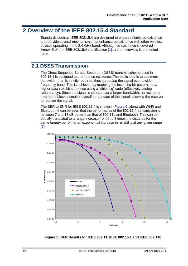
2.1 DSSS Transmission The Direct Sequence Spread Spectrum (DSSS) transmit scheme used in 802.15.4 is designed to promote co-existence. The basic idea is to use more bandwidth than is strictly required, thus spreading the signal over a wider frequency band. This is achieved by mapping the incoming bit-pattern into a higher data-rate bit sequence using a “chipping” code (effectively adding redundancy). Since the signal is spread over a larger bandwidth, narrow-band interferers block a smaller overall percentage of the signal, allowing the receiver to recover the signal.
The BER to SNR for IEEE 802.15.4 is shown in Figure 5, along with Wi-Fi and Bluetooth. It can be seen that the performance of the 802.15.4 transmission is between 7 and 18 dB better than that of 802.11b and Bluetooth. This can be directly translated to a range increase from 2 to 8 times the distance for the same energy per bit, or an exponential increase in reliability at any given range [7].
1.0E-09
1.0E-08
1.0E-07
1.0E-06
1.0E-05
1.0E-04
1.0E-03
1.0E-02
1.0E-01
1.0E+00
-10 -5 0 5 10 15
SNR (dB)
Bit
Erro
r Rat
e
802.15.4
802.11b (2Mbps)
802.11b (11Mbps)
Bluetooth
Figure 5: BER Results for IEEE 802.11, IEEE 802.15.1 and IEEE 802.11b

Co-existence of IEEE 802.15.4 at 2.4 GHz Application Note
JN-AN-1079 v1.1 © NXP Laboratories UK 2013 13
2.2 Protocol The IEEE 802.15.4 standard provides several mechanisms to enhance co-existence.
Dynamic Channel Selection The PHY layer provides the ability to measure the energy, and thus the interference, that is present on a particular channel. This capability is used by the MAC and higher layers to allow users to select the best available channel for operation.
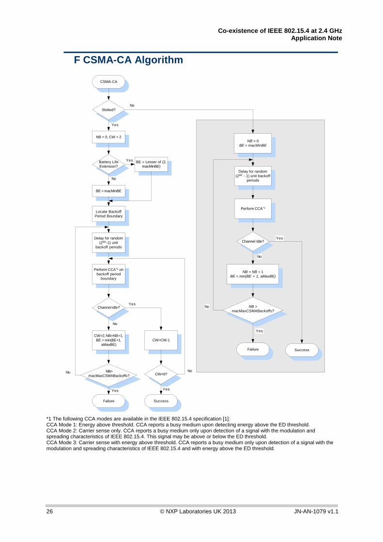
CSMA-CA The CSMA-CA (Carrier Sense Multiple Access with Collision Avoidance) channel access mechanism is a “listen before you talk” strategy employed by the PHY layer, providing the ability to sample a channel and report whether the channel is “Clear To Transmit”. The CSMA-CA algorithm is shown in Appendix F.
Note: The wait intervals increase exponentially and are random, making subsequent collisions less likely.
Acknowledged Transmission and Retries To ensure successful reception of data, an acknowledged frame delivery protocol is supported to increase transfer reliability. If the receiving device is unable to handle the received data frame for any reason, the message is not acknowledged. If the originator does not receive an acknowledgment, it assumes that the transmission was unsuccessful and retries the frame transmission. This is particularly useful in dealing with frequency hopping interference, such as from Bluetooth, which may interfere with a first transmission attempt but will usually have hopped to a different part of the spectrum for the retry.
2.3 Data-Rate While lower data-rates can meet the requirements of many applications, one of the best ways to promote co-existence is to reduce channel occupancy time. The IEEE 802.15.4-2003 standard defines the relatively high data-rate of 250 kbps for the 2.4-GHz PHY (see Table 1: IEEE 802.15.4-2003 Frequency Bands and Data Rates and [11]).

Co-existence of IEEE 802.15.4 at 2.4 GHz Application Note
14 © NXP Laboratories UK 2013 JN-AN-1079 v1.1
3 Co-existence Concerns The number of wireless standards might reasonably raise concerns about overcrowding in the unlicensed 2.4-GHz ISM band. Therefore, the performance of IEEE 802.15.4 in the presence of interferers such as Wi-Fi and Bluetooth should be evaluated, particularly for applications in which resources and bandwidth allocation cannot be guaranteed.
These co-existence concerns are often used by promoters of competing technologies in an attempt to gain commercial advantage. Interestingly, these proprietary technologies use the sub-GHz ISM bands, also crowded with traffic from consumer devices such as cordless phones and wireless music systems. Claims are rarely supported by independent and unbiased evidence, fueling speculation on the inadequacies of the test methods employed.
“With the existence of evidence to the contrary, conclusions drawn in whitepapers supported by a proprietary competitive wireless technology should be considered questionable at best”, [12].
The sections of this chapter aim to provide a reasonable assessment of the co-existence issues, as well as presenting the findings of both independent analytical and empirical studies into the co-existence performance of LR-WPANs in the 2.4-GHz ISM band.
3.1 Circumstantial Evidence The wireless systems that have recently achieved worldwide success and popularity are all based on industry standards, such as Bluetooth, DECT and GSM. Working to a standard protocol offers the major advantage of allowing devices from different manufacturers to interoperate with each other. In addition, the adoption of these standards by industry leaders has allowed the inclusion of features which would be costly for smaller enterprises to develop.
The IEEE Standards Association is an internationally acknowledged and respected group dealing in standards development with voluntary members working in an open and collaborative manner. A significant contribution has been the IEEE 802 standards family, which includes LR-WPANs, Bluetooth and Wi-Fi. For a standard in the IEEE 802 family to be approved, a ‘Co-existence Assurance’ document must be provided and approved. The co-existence approval process usually involves IEEE members working together to ensure that all 802 wireless standards can co-exist in the same space at the same time (further details on the Co-existence of 802.15.4 with other IEEE standards can be found in Annex E of the IEEE 802.15.4-2003 standard [1]).
The ZigBee protocol standard, which is built on top of IEEE 802.15.4, provides the additional benefits of a well-developed wireless networking standard, designed, built and supported by hundreds of the world’s leading technology companies. The ZigBee Alliance has more than 225 member companies, spending billions of dollars around ZigBee. Most of these companies have thoroughly and independently investigated ZigBee (and the underlying IEEE 802.15.4 standard) prior to investing funds to develop new ZigBee products and services.
IEEE 802.15.4 and ZigBee products are regularly demonstrated around the world at some of largest consumer electronics tradeshows, such as Electronica,

Co-existence of IEEE 802.15.4 at 2.4 GHz Application Note
JN-AN-1079 v1.1 © NXP Laboratories UK 2013 15
Hannover Messe and Wireless Japan. These shows often present the harshest locations for RF technologies to operate, with dozens of wireless networks including Wi-Fi, Bluetooth and other RF traffic, yet users and demonstrators of ZigBee networks report reliable performance [12].
3.2 Independent Co-existence Studies In the real world, there are many possible co-existence scenarios, with different network sizes and configurations, interference sources and environmental conditions. In addition, the performance metrics are often determined by the particular application under test.
In performing co-existence studies, difficulties can arise in determining the typical characteristics of an interferer and the expected traffic rates in the network:
• In defining the characteristics of an interference source, important factors are transmitter payload size, inter-packet delay and output power.
For Bluetooth, the output power is especially important since dynamic power control is often employed.
• For WLAN, typical characteristics are hard to define. For example, the characteristics of a domestic or small commercial WLAN system are intermittent and variable over time.
• Other significant factors are traffic rates and proximity to the transmitter.
For WLAN, if the current data-rate cannot be maintained, adaptive rate selection is employed (see Section 1.2.2).
The WLAN Access Point (AP) is often a significant source of interference due its large duty cycles, while the clients transmit short acknowledgment packets and have a considerably smaller duty cycle (assuming the clients are mainly receiving data from the AP).
Given the above and the difficulty in defining the characteristics of a ‘typical’ interferer, test scenarios often reflect the worst case and have limited real world relevance, giving overly pessimistic results.
The rest of this section is split into:
• ‘Empirical data studies’ in which experimental measured data is obtained with the use of a more practical approach – see Section 3.2.1
• ‘Analytical studies’ in which elemental parts of the PHY and MAC behaviour are modelled, and simulated data is obtained – see Section 3.2.2
The papers referenced are considered to take a reasonable approach to interference modelling and testing, providing credible test results and offering useful real world metrics, helping to define recommendations for the co-existence of IEEE 802.14.5 networks.

Co-existence of IEEE 802.15.4 at 2.4 GHz Application Note
16 © NXP Laboratories UK 2013 JN-AN-1079 v1.1
3.2.1 Empirical Data Studies This section presents a number of published empirical studies.
A. Sikora The work carried out by A. Sikora in [8], and extended in [9], offers a good early insight into the co-existence performance of IEEE 802.15.4. It must be noted that these tests were set up to represent the worst case scenario and are stated in the report as having “limited real world relevance”.
• For the WLAN interferer, the following statement is made: “The IEEE802.11b system was run with the highest possible utilisation rate for a prolonged time. In practical life, this utilisation rate is achieved only at peak times”. However, some reasonable conclusions are drawn.
• For Wi-Fi interference, it can be seen that a channel offset of ~10MHz dramatically reduces the IEEE 802.15.4 Packet Error Rate (PER) from 92% to ~30%. The key point to note here is that the separation of the Wi-Fi transmitter from the LR-WPAN is only 2 m throughout the test. It is also of interest to note the significant amount of time attributed to the client/server processing overhead during the WLAN FTP transfer, highlighting the importance of measured results.
• The Bluetooth interferer characteristics are also worst case. Using two parallel FTP links in close proximity, an IEEE 802.15.4 PER of less than 10% is achieved.
M. Petrova et al. The paper by M. Petrova et al. [7] briefly covers co-existence with IEEE 802.11b/g, in Section V of the paper. Measurements are made for different offsets between the central frequencies of the IEEE 802.15.4 and IEEE 802.11b/g channels. Different packet sizes for IEEE 802.15.4 are also taken into account, although no details of the interferer traffic characteristics are provided. Separation between the IEEE 802.15.4 and WLAN sources is fixed at 3.5 m. The following conclusions are stated: “Our measurement showed that there should be at least 7MHz offset between the operational frequencies for a satisfactory performance of the IEEE 802.15.4”. The results also show that using small packets of 20 bytes exhibits significantly better co-channel rejection than using the maximum packet size of 127 bytes.
K. Shuaib et al. More recent studies include that done by K. Shuaib et al. [10]. This study was carried out in an office environment using an IEEE 802.11g interferer with a data throughput of 9.8 Mbps. The bi-directional ZigBee data throughput was also set near to the full channel capacity at 115 kbps (see the NXP Application Note JN-AN-1035, “Calculating 802.15.4 Data Rates”). The results show that for ZigBee nodes placed between 3 m and 6 m either side of the WLAN transmitter, the ZigBee throughput is decreased by between 10% and 22%. It must be noted that this is for co-channel operation. Separation distances greater than 6 m and channel offsets are not considered. The interesting point to note in this paper is the considerable effect that Bluetooth interference has on the WLAN throughput - up to 12% worst case, compared with the negligible impact on throughput due to ZigBee interference when operating in close proximity.

Co-existence of IEEE 802.15.4 at 2.4 GHz Application Note
JN-AN-1079 v1.1 © NXP Laboratories UK 2013 17
ZigBee Alliance The final study presented here has been carried out by the ZigBee Alliance [12]. Rather than defining specific interferer characteristics, this study uses data captured at Hannover Messe 2007 – Europe’s largest electronics show. A very active air environment provides ambient interference, composed of multiple WLAN, Bluetooth and IEEE 802.15.4 networks, as well as numerous proprietary wireless technologies. The performance of a ZigBee network is recorded using a network analyser tool. The results show a 2.2% packet loss rate at the NWK layer (with application level retries, this could be reduced to an effective loss rate of 0%).
3.2.2 Analytical Studies The main body of analytical co-existence studies have been carried out by S.Shin et al. in [13], [14] and [15].
The initial work carried out in [13] assumes both the WLAN and LR-WPAN are transmitting blind, without consideration for the channel state, i.e. the carrier sense CCA mode is used (CCA-CS). The WLAN interferer is modelled as band-limited additive white Gaussian noise. Consideration is also given to the non-uniform power spectral density distribution of the IEEE 802.11b signal. Simulations are performed using the OPNET*1 network simulator to model the IEEE 802.15.4 and IEEE 802.11b access protocols, using a 11-Mbps data-rate for WLAN with a 1500-byte packet payload. A 105-byte packet payload is used for the WPAN. Results show a 0.1% PER for the IEEE 802.15.4 transmission when at a separation of 8m from the WLAN transmitter (co-channel). Frequency offset is also analysed. The following conclusions are made: “If the distance between the IEEE 802.15.4 and IEEE 802.11b is longer than 8 m, the interference of the IEEE 802.11b does not affect the performance of the IEEE802.15.4. If the frequency offset is larger than 7 MHz, the interference effect of the IEEE 802.11b is negligible to the performance of the IEEE 802.15.4”.
The findings of [13] are expanded further in [14] to consider the performance of an IEEE 802.15.4 link under the interference of a saturated IEEE 802.11b network. For a saturated WLAN network, the probability of two nodes transmitting at the same time is increased. Therefore, from the viewpoint of IEEE 802.15.4, a IEEE 802.11b packet collision is a more powerful interferer than a single source transmission. Here, both IEEE 802.15.4 and the IEEE 802.11b interferer are considered to be in saturated traffic conditions. Transmission output powers were set to 15 dBm for WLAN and 0 dBm for IEEE 802.15.4. The results show a significant increase in PER with the increase in transmitting WLAN nodes. However, even when considering 20 WLAN nodes, the IEEE 802.15.4 PER is below 10% for separations of 8 m and above (co-channel).
At the time of writing, the latest paper [15] includes the PER analysis under the influence of WLAN and/or Bluetooth. From the co-existence results with Bluetooth, it can be seen that the Bluetooth interferer has much less of an effect on the IEEE 802.15.4 PER than WLAN, concluding with the statement “The dominant interference source is WLAN”. The suggested separation figure from saturated WLAN interference is 11.55 m, assuming 20 operational co-channel WLAN nodes compared with a 6.2-m separation for a Bluetooth interferer.
It is important to note that co-existence criteria for WLAN and Bluetooth stated above ([14], [15]) defines an acceptable PER threshold of 0.001%. This is considered an unrealistic threshold for all but a few data-critical applications (and

Co-existence of IEEE 802.15.4 at 2.4 GHz Application Note
18 © NXP Laboratories UK 2013 JN-AN-1079 v1.1
contradicts the co-existence criteria statement made in [13], which implies an acceptable PER threshold of 0.1%). It is reasonable to assume that most IEEE 802.15.4 applications would be able to tolerate a PER of between 1 and 10%, particularly if application level retries are employed, without significant impact on battery life.
*1 OPNET and OPNET Modeler are registered trademarks of OPNET Technologies, Inc.
Co-existence of IEEE 802.15.4 at 2.4 GHz Application Note
JN-AN-1079 v1.1 © NXP Laboratories UK 2013 19
4 Conclusions In general, the co-existence of IEEE 802.15.4 with both WLAN and Bluetooth networks is possible with an acceptable performance, when nodes are not in a close proximity of each other and/or channels are adequately selected to prevent overlapping.
WLAN It is clear that the effects of WLAN on IEEE 802.15.4 cannot be ignored. Although co-channel operation can be avoided by evaluation of the RF environment prior to installation, in the case where multiple access points exist, co-channel operation must be considered. From the papers reviewed in Sections 3.2.1 and 3.2.2, and experience gained in the field, some co-existence criteria can be established:
• To achieve satisfactory IEEE 802.15.4 performance in the presence of WLAN interference, a channel centre-frequency offset of 7 MHz is recommended.
• For co-channel operation, a physical separation from the WLAN Access Point (AP) of 8 m is recommended to achieve a PER of 1%. For a particularly saturated WLAN link, 9-10 m may be necessary.
Bluetooth Bluetooth interference is less of an issue. The packet retry mechanism employed by IEEE 802.15.4 ensures re-transmission of packets corrupted by Bluetooth interference. Bluetooth may interfere with a first transmission attempt, but will usually have hopped to a different part of the spectrum for the retry.
To achieve satisfactory IEEE 802.15.4 performance in the presence of Bluetooth interference, a separation distance of 2 m is recommended.
Note: The effects of IEEE 802.15.4 on WLAN can effectively be ignored. Bluetooth however has a significant effect on WLAN throughput.
Co-existence of IEEE 802.15.4 at 2.4 GHz Application Note
20 © NXP Laboratories UK 2013 JN-AN-1079 v1.1
5 Moderating Interference Effects This chapter presents a number of methods for reducing the effects of interference on an IEEE 802.15.4 network.
Channel Selection The channels 25 and 26 can be used in North America for operation clear of Wi-Fi interference.
For deployment in an environment where resource planning and bandwidth allocation can be guaranteed (see Section 1.2.5 ‘Channel Allocation’), a channel centre-frequency offset of 7 MHz is recommended to ensure acceptable co-existence with Wi-Fi. The non-overlapping channels (1, 6 and 11 for North America, 1, 7 and 13 for Europe) can also be used to avoid Wi-Fi interference where non-overlapping Wi-Fi channels have been allocated.
Physical Separation Ensuring a physical separation of at least 8 m from a Wi-Fi Access Point (AP) will ensure acceptable co-channel IEEE 802.15.4 performance.
Mesh Networking The ZigBee protocol offers the additional benefits of a self-organising and self-healing dynamic mesh network. In this kind of environment, path diversity offers better channel use. If a chosen path fails as a result of interference, the network will select a different path.
Network Layer Frequency Agility The upper protocol layers of the PAN Co-ordinator can perform dynamic channel selection in response to channel impairment. Mechanisms for this are available in IEEE 802.15.4, such as LQI (Link Quality Indicator), which assesses the current channel status on a packet-by-packet basis. Although not defined in the IEEE 802.15.4 specification, frequency agility measures are being addressed in ZigBee PRO with the addition of ‘network manager’ attributes such as NLME-JOIN.request, although the specific mechanisms used to decide on a channel change are selected by the developers.
Activity Signalling to Aid System Co-location Issues Activity signalling can be employed when two RF systems are co-located in the same device. It is used to indicate transmission/reception activity and enable time-division multiplexing between the two systems. The information passed between the primary and secondary systems will usually indicate when the primary system is active and when the secondary system has priority traffic. These signals require very accurate timing and low latency, so they are not normally passed via a host operating system but, instead, over dedicated hardware co-existence signalling connections.

Co-existence of IEEE 802.15.4 at 2.4 GHz Application Note
JN-AN-1079 v1.1 © NXP Laboratories UK 2013 21
Neighbour Piconet Support The PAN Co-ordinator can co-ordinate the timings of its network with other systems. This type of neighbour ‘piconet’ capability may further alleviate interference with other LR-WPANs
Network Planning For the initial deployment of IEEE 802.15.4 networks, a site survey can be performed to evaluate the RF environment, logging results over a period of time. PER analysis can also be performed on specific node placements. To assist with network planning, NXP offer the following tools as Application Notes:
JN-AN-1006: Packet Error Rate Testing JN-AN-1014: Site Survey Tool JN-AN-1059: Wireless Network Deployment Guidelines
Co-existence of IEEE 802.15.4 at 2.4 GHz Application Note
22 © NXP Laboratories UK 2013 JN-AN-1079 v1.1
Appendices
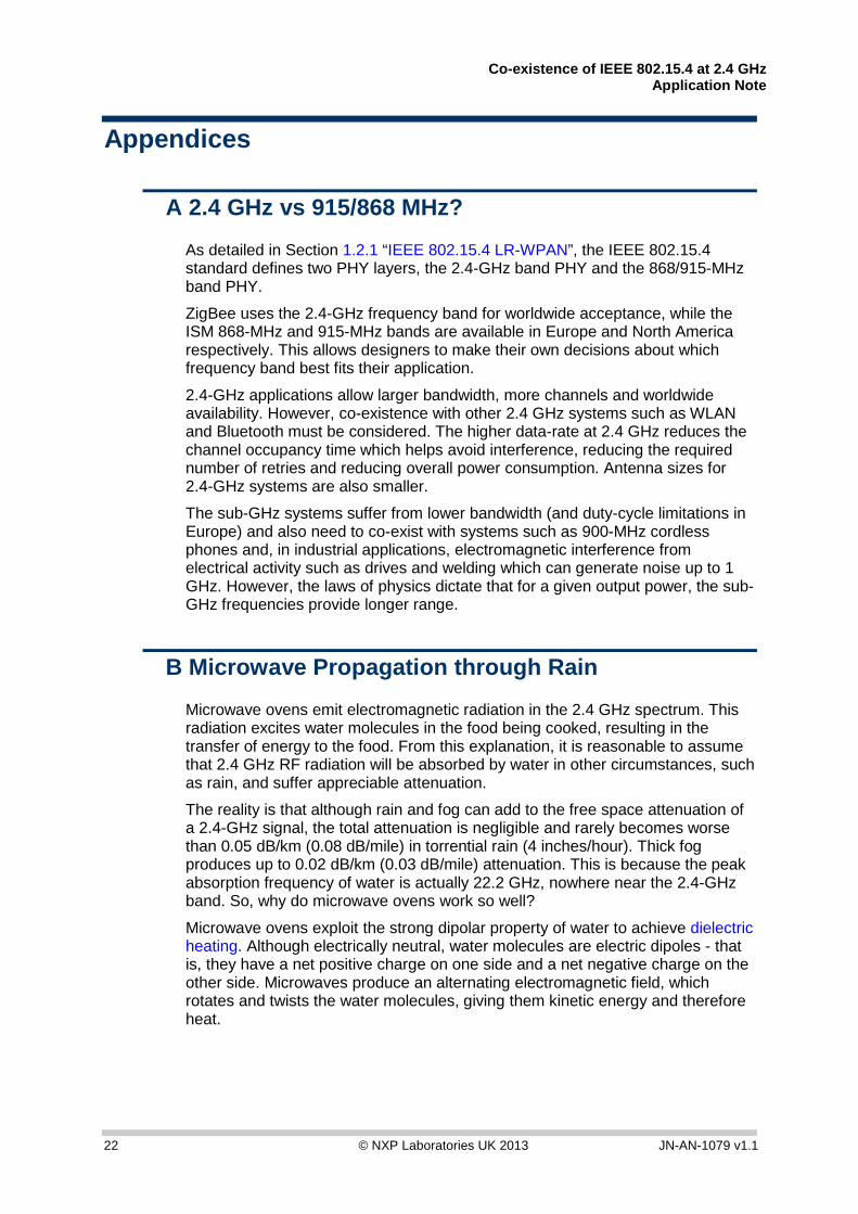
A 2.4 GHz vs 915/868 MHz?
As detailed in Section 1.2.1 “IEEE 802.15.4 LR-WPAN”, the IEEE 802.15.4 standard defines two PHY layers, the 2.4-GHz band PHY and the 868/915-MHz band PHY.
ZigBee uses the 2.4-GHz frequency band for worldwide acceptance, while the ISM 868-MHz and 915-MHz bands are available in Europe and North America respectively. This allows designers to make their own decisions about which frequency band best fits their application.
2.4-GHz applications allow larger bandwidth, more channels and worldwide availability. However, co-existence with other 2.4 GHz systems such as WLAN and Bluetooth must be considered. The higher data-rate at 2.4 GHz reduces the channel occupancy time which helps avoid interference, reducing the required number of retries and reducing overall power consumption. Antenna sizes for 2.4-GHz systems are also smaller.
The sub-GHz systems suffer from lower bandwidth (and duty-cycle limitations in Europe) and also need to co-exist with systems such as 900-MHz cordless phones and, in industrial applications, electromagnetic interference from electrical activity such as drives and welding which can generate noise up to 1 GHz. However, the laws of physics dictate that for a given output power, the sub-GHz frequencies provide longer range.
B Microwave Propagation through Rain
Microwave ovens emit electromagnetic radiation in the 2.4 GHz spectrum. This radiation excites water molecules in the food being cooked, resulting in the transfer of energy to the food. From this explanation, it is reasonable to assume that 2.4 GHz RF radiation will be absorbed by water in other circumstances, such as rain, and suffer appreciable attenuation.
The reality is that although rain and fog can add to the free space attenuation of a 2.4-GHz signal, the total attenuation is negligible and rarely becomes worse than 0.05 dB/km (0.08 dB/mile) in torrential rain (4 inches/hour). Thick fog produces up to 0.02 dB/km (0.03 dB/mile) attenuation. This is because the peak absorption frequency of water is actually 22.2 GHz, nowhere near the 2.4-GHz band. So, why do microwave ovens work so well?
Microwave ovens exploit the strong dipolar property of water to achieve dielectric heating. Although electrically neutral, water molecules are electric dipoles - that is, they have a net positive charge on one side and a net negative charge on the other side. Microwaves produce an alternating electromagnetic field, which rotates and twists the water molecules, giving them kinetic energy and therefore heat.

Co-existence of IEEE 802.15.4 at 2.4 GHz Application Note
JN-AN-1079 v1.1 © NXP Laboratories UK 2013 23
C LR-WPAN 2.4-GHz PHY Channel Frequencies
Channel ID Lower Frequency
Centre Frequency
Upper Frequency
11 2404 2405 2406
12 2409 2410 2411
13 2414 2415 2416
14 2419 2420 2421
15 2424 2425 2426
16 2429 2430 2431
17 2434 2435 2436
18 2439 2440 2441
19 2444 2445 2446
20 2449 2450 2451
21 2454 2455 2456
22 2459 2460 2461
23 2464 2465 2466
24 2469 2470 2471
25 2474 2475 2476
26 2479 2480 2481

Co-existence of IEEE 802.15.4 at 2.4 GHz Application Note
24 © NXP Laboratories UK 2013 JN-AN-1079 v1.1
D Wi-Fi Channel Frequencies
Regulatory Domains
Channel ID
Lower Freq.
Centre Freq.
Upper Freq.
USA & Canada
Europe Spain France Japan
1 2401 2412 2423 X X X
2 2404 2417 2428 X X X
3 2411 2422 2433 X X X
4 2416 2427 2438 X X X
5 2421 2432 2443 X X X
6 2426 2437 2448 X X X
7 2431 2442 2453 X X X
8 2436 2447 2458 X X X
9 2441 2452 2463 X X X
10 2446 2457 2468 X X X X X
11 2451 2462 2473 X X X X X
12 2456 2467 2478 X X X
13 2461 2472 2483 X X X
14 2473 2484 2495 X*1
*1 802.11b only

Co-existence of IEEE 802.15.4 at 2.4 GHz Application Note
JN-AN-1079 v1.1 © NXP Laboratories UK 2013 25
E Wi-Fi Modulation and Coding Schemes
*1 Spreading/Coding Schemes used:11 Chip Barker Code, CCK and PBCC. *2 DSSS Mode *3 OFDM Mode *4 Support for 802.11b backwards compatibility.
Transmit Scheme Modulation
IEEE Standard
Freq. Data-rates DSSS*1 OFDM
(D)BPSK (Data-rates)
(D)QPSK (Data-rates)
QAM-16 (Data-rates)
QAM-64 (Data-rates)
802.11b 2.4GHz 1,2,5.5,11 X X
(1)*2
X
(2, 5.5, 11)*2
802.11g 2.4GHz (1,2,5.5,11)*4
6, 9, 12, 18, 24, 36, 48, 54
X X X
(6,9)*3
X
(12,18)*3
X
(24, 36)*3
X
(48, 54)*3
Co-existence of IEEE 802.15.4 at 2.4 GHz Application Note
26 © NXP Laboratories UK 2013 JN-AN-1079 v1.1
F CSMA-CA Algorithm
Channel Idle?
NB = 0BE = macMinBE
Delay for random(2BE - 1) unit backoff
periods
Perform CCA*1
NB = NB + 1BE = min(BE + 1, aMaxBE)
NB >macMaxCSMABackoffs?
Failure Success
No
Yes
Yes
No
CSMA-CA
Slotted?
NB = 0, CW = 2
Battery LifeExtension?
BE = Lesser of (2,macMinBE)
BE = macMinBE
Locate BackoffPeriod Boundary
Delay for random(2BE-1) unit
backoff periods
Perform CCA*1 onbackoff period
boundary
Channel idle?
CW=2, NB=NB+1,BE = min(BE+1,
aMaxBE)
NB>macMaxCSMABackoffs? CW=0?
CW=CW-1
Failure Success
Yes
No
Yes
No
Yes Yes
Yes
No
No
No
*1 The following CCA modes are available in the IEEE 802.15.4 specification [1]: CCA Mode 1: Energy above threshold. CCA reports a busy medium upon detecting energy above the ED threshold. CCA Mode 2: Carrier sense only. CCA reports a busy medium only upon detection of a signal with the modulation and spreading characteristics of IEEE 802.15.4. This signal may be above or below the ED threshold. CCA Mode 3: Carrier sense with energy above threshold. CCA reports a busy medium only upon detection of a signal with the modulation and spreading characteristics of IEEE 802.15.4 and with energy above the ED threshold.

Co-existence of IEEE 802.15.4 at 2.4 GHz Application Note
JN-AN-1079 v1.1 © NXP Laboratories UK 2013 27
Revision History Version Date Description
1.0 18-Feb-2008 First release
1.1 8-Nov-2013 Various updates made

Co-existence of IEEE 802.15.4 at 2.4 GHz Application Note
28 © NXP Laboratories UK 2013 JN-AN-1079 v1.1
Important Notice Limited warranty and liability — Information in this document is believed to be accurate and reliable. However, NXP Semiconductors does not give any representations or warranties, expressed or implied, as to the accuracy or completeness of such information and shall have no liability for the consequences of use of such information. NXP Semiconductors takes no responsibility for the content in this document if provided by an information source outside of NXP Semiconductors.
In no event shall NXP Semiconductors be liable for any indirect, incidental, punitive, special or consequential damages (including - without limitation - lost profits, lost savings, business interruption, costs related to the removal or replacement of any products or rework charges) whether or not such damages are based on tort (including negligence), warranty, breach of contract or any other legal theory.
Notwithstanding any damages that customer might incur for any reason whatsoever, NXP Semiconductors’ aggregate and cumulative liability towards customer for the products described herein shall be limited in accordance with the Terms and conditions of commercial sale of NXP Semiconductors.
Right to make changes — NXP Semiconductors reserves the right to make changes to information published in this document, including without limitation specifications and product descriptions, at any time and without notice. This document supersedes and replaces all information supplied prior to the publication hereof.
Suitability for use — NXP Semiconductors products are not designed, authorized or warranted to be suitable for use in life support, life-critical or safety-critical systems or equipment, nor in applications where failure or malfunction of an NXP Semiconductors product can reasonably be expected to result in personal injury, death or severe property or environmental damage. NXP Semiconductors and its suppliers accept no liability for inclusion and/or use of NXP Semiconductors products in such equipment or applications and therefore such inclusion and/or use is at the customer’s own risk.
Applications — Applications that are described herein for any of these products are for illustrative purposes only. NXP Semiconductors makes no representation or warranty that such applications will be suitable for the specified use without further testing or modification.
Customers are responsible for the design and operation of their applications and products using NXP Semiconductors products, and NXP Semiconductors accepts no liability for any assistance with applications or customer product design. It is customer’s sole responsibility to determine whether the NXP Semiconductors product is suitable and fit for the customer’s applications and products planned, as well as for the planned application and use of customer’s third party customer(s). Customers should provide appropriate design and operating safeguards to minimize the risks associated with their applications and products.
NXP Semiconductors does not accept any liability related to any default, damage, costs or problem which is based on any weakness or default in the customer’s applications or products, or the application or use by customer’s third party customer(s). Customer is responsible for doing all necessary testing for the customer’s applications and products using NXP Semiconductors products in order to avoid a default of the applications and the products or of the application or use by customer’s third party customer(s). NXP does not accept any liability in this respect.
Export control — This document as well as the item(s) described herein may be subject to export control regulations. Export might require a prior authorization from competent authorities.
NXP Laboratories UK Ltd (Formerly Jennic Ltd)
Furnival Street Sheffield S1 4QT
United Kingdom
Tel: +44 (0)114 281 2655 Fax: +44 (0)114 281 2951
For the contact details of your local NXP office or distributor, refer to:
www.nxp.com
For online support resources, visit the Wireless Connectivity TechZone:
www.nxp.com/techzones/wireless-connectivity


