CO 2 capture from oxy-fuel combustion power plants Yukun Hu Licentiate Thesis 2011 KTH Royal Institute of Technology School of Chemical Science and Engineering Department of Chemical Engineering and Technology Energy Processes Stockholm, Sweden
Transcript
CO2 capture from oxy-fuel combustion power plants
Yukun Hu
Licentiate Thesis
2011
KTH Royal Institute of Technology School of Chemical Science and Engineering
Department of Chemical Engineering and Technology Energy Processes
II. Hu Y., Yan J., Li H., 2011. Effects of flue gas recycle on the performance of particles, SOx
and NOx removal in oxy-coal power generation system. International Conference on
Applied Energy, Perugia, Italy, May 16-18.
III. Hu Y., Li H., Yan J., 2010. Integration of evaporative gas turbine with oxy-fuel combustion
for carbon dioxide capture. International Journal of Green Energy 7, 615-631.
IV. Hu Y., Li H., Yan J., 2012. Techno-economic evaluation of the evaporative gas turbine
cycles combined with different CO2 capture techniques. Applied Energy 89: 303-314.
Other publications which are not included in this thesis:
V. Hu Y., Yan J., Li H. Effects of flue gas recycle on oxy-coal power generation system.
Applied Energy, under review.
VI. Li H., Flores S., Hu Y., Yan J., 2009. Simulation and optimization of evaporative gas turbine
with chemical absorption for carbon dioxide capture. International Journal of Green Energy
6, 527-539.
My contribution to the appended papers Papers I, II, III, IV, and V are the continuous work of the previous studies. The basic concepts
and ideas are from the supervisors/co-authors. I did the specific tasks and wrote the first draft of
the papers. Co-authors made valuable revision to improve the drafts. Additionally, I am a co-
author of Paper VI, in which I did validation of the simulation.
VI
VII
Table of Contents
Abstract .................................................................................................................................................... I
Acknowledgments ................................................................................................................................ III
List of Appended Papers ...................................................................................................................... V
Table of Contents .............................................................................................................................. VII
List of Figures ...................................................................................................................................... IX
List of Tables ........................................................................................................................................ XI
Abbreviations and Nomenclatures .................................................................................................. XIII
2. Studied systems .................................................................................................................................. 9
2.1. Reference systems and subsystems ................................................................................................ 9
2.1.1. Conventional pulverized coal power plant ............................................................................ 9
2.1.2. Evaporative gas turbine (EvGT) cycle ................................................................................. 10
2.1.3. Air separation unit (ASU) ....................................................................................................... 10
2.1.4. CO2 conditioning process ...................................................................................................... 11
6. Future work ...................................................................................................................................... 33
How is the performance of the EvGT cycle integrated with oxy-fuel combustion for CO2
capture from techno-economic point of view, such as electrical efficiency, cost of
electricity (COE), and cost of CO2 avoidance (COA)?
1.4. Objective of this study
The presented study aims to make an investigation on oxy-coal combustion processes and oxy-
natural gas combustion processes. Detailed comparisons and analyses have been done to
investigate characteristics of flue gas in oxy-coal combustion processes for CO2 capture, such as
the effect of impurities on flue gas recycle (FGR) rate and ratio, and the flue gas cleaning unit
arrangement associated with various flue gas recycle options (See Papers I and II).
Furthermore, to continue our previous work on system integration of evaporative gas turbine
(EvGT) towards higher efficiency, the feasibility study of the EvGT cycle integrated with oxy-
fuel combustion have to be carried out and compared to its integration with other technology
(post-combustion capture) from technical and economic points of view (See Papers III and IV).
1.5. Thesis outline
The schematic diagram of the thesis structure is illustrated in Figure 1.3. The characterization of
flue gas as well as the recycle options were first identified in order to make a full understanding of
oxy-coal combustion processes (Level I); then the simulation and optimization of EvGT cycle
with oxy-fuel combustion was carried out to obtain optimized technical parameters (Level II) and
compared to EvGT cycle with chemical absorption for further economic evaluation (Level III).
The characterization
of flue gas recycle in
oxy-coal combustion
Simulation and optimization of EvGT
integrated with oxy-fuel combustion
Economic evaluation of EvGT integrated
with oxy-fuel combustion vs. Chemical
absorption for CO2 capture
Level Ⅰ
Level Ⅱ
Level Ⅲ
Provide better understanding
Obtain optimal operation parameters
Comparison from economic point of view
The effects of flue
gas recycle in oxy-
coal power system
and
Figure 1.3 Schematic diagram of the thesis structure
CO2 capture form oxy-fuel combustion power plants
8
The thesis is a summary of four scientific papers, which are appended. The outline consists of the
following six chapters.
Chapter 1 Introduction: includes background information, literature review, problems, and objective
etc.
Chapter 2 Studied systems: provides basic information of the studied systems including reference air
combustion systems and oxy-fuel combustion systems. The system configurations and
boundary conditions are also discussed.
Chapter 3 Methodology: introduces research approaches, assumptions and the reference data used
for simulations.
Chapter 4 Results and discussions: presents results of theoretical and modeling analysis, system
performance such as optimized parameters and electrical efficiency etc., as well as
economic evaluations.
Chapter 5 Conclusions: highlights major conclusions for this study and future work.
Chapter 6 Future work: suggestions for continuing the study.
9
2. Studied systems
The present thesis studies the integration of reference power generation systems with oxy-fuel
combustion technology for CO2 capture based on the following complete systems and
subsystems:
Conventional pulverized coal fired power plant (reference system)
Natural gas evaporative gas turbine (EvGT) cycle power plant (reference system)
Air separation unit (ASU) (Subsystem)
CO2 conditioning process (Subsystem)
Brief descriptions of the studied systems and subsystems are presented below.
2.1. Reference systems and subsystems
2.1.1. Conventional pulverized coal power plant
Figure 2.1 shows the schematic diagram of a conventional pulverized coal power plant, which has
7 water preheaters with steam extraction from the steam turbine. Such a kind of power plant can
effectively reduce the exergy loss during heat transfer. Coal is conveyed from an external stack
and ground to fine powder in the coal mill. There it is mixed with around 20 % of the preheated
combustion air and transported to the furnace; the remaining 80 % of air is supplied directly to
the furnace chamber. Water from the steam cycle flows vertically up the water wall of the boiler
and turns into steam, and then it goes through a superheated where its temperature and pressure
increase rapidly to around 200 bar and 570 °C (dependent on the specific technology). The steam
flows through a series of steam turbines to spin an electrical generator. The pan-steam from the
turbines is cooled, condensed back into water, and preheated before being returned to the steam
generator to start the process over. The flue gas is ventilated after emission control processes
(dust removal, desulfurization and denitrification etc).
ESPFGD
MillCoal
Air
Deaerator
HP G
Boiler
FD Fan
Condensor
LP Pump
HP PumpAP
H
Electric HeaterSCR
SPH
Stack
IP LP
Figure 2.1 Schematic diagram of a conventional pulverized coal power plant (Hu et al., 2011b)
CO2 capture form oxy-fuel combustion power plants
10
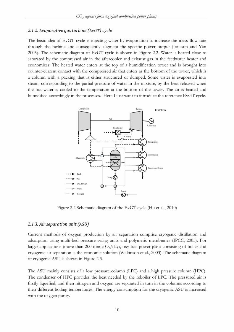
2.1.2. Evaporative gas turbine (EvGT) cycle
The basic idea of EvGT cycle is injecting water by evaporation to increase the mass flow rate
through the turbine and consequently augment the specific power output (Jonsson and Yan
2005). The schematic diagram of EvGT cycle is shown in Figure 2.2. Water is heated close to
saturated by the compressed air in the aftercooler and exhaust gas in the feedwater heater and
economizer. The heated water enters at the top of a humidification tower and is brought into
counter-current contact with the compressed air that enters as the bottom of the tower, which is
a column with a packing that is either structured or dumped. Some water is evaporated into
steam, corresponding to the partial pressure of water in the mixture, by the heat released when
the hot water is cooled to the temperature at the bottom of the tower. The air is heated and
humidified accordingly in the processes. Here I just want to introduce the reference EvGT cycle.
Combustor
Compressor
GT
Generator
Recuperator
Economizer
Aftercooler
CO2 Stream
Fuel
Water
Air
EvGT Cycle
Feedwater Heater
Coolant
Cooling
Turbine
Humidification Tower
Pump
Pump
Figure 2.2 Schematic diagram of the EvGT cycle (Hu et al., 2010)
2.1.3. Air separation unit (ASU)
Current methods of oxygen production by air separation comprise cryogenic distillation and
adsorption using multi-bed pressure swing units and polymeric membranes (IPCC, 2005). For
larger applications (more than 200 tonne O2/day), oxy-fuel power plant consisting of boiler and
cryogenic air separation is the economic solution (Wilkinson et al., 2003). The schematic diagram
of cryogenic ASU is shown in Figure 2.3.
The ASU mainly consists of a low pressure column (LPC) and a high pressure column (HPC).
The condenser of HPC provides the heat needed by the reboiler of LPC. The pressured air is
firstly liquefied, and then nitrogen and oxygen are separated in turn in the columns according to
their different boiling temperatures. The energy consumption for the cryogenic ASU is increased
with the oxygen purity.
2. Studied systems
11
Air
Heat
Exchanger
1
Heat
Exchanger
2
Oxygen with samll amount of Argon
Nitrogen
Splitter
Turbine 2
Turbine 1
Air Separation Units
CompressorFilter
Condensor
Air
Water vapor, impurities
Preliminary purified oxygen
Oxygen
Nitrogen
Heat
Water
Valve 1
Valve 2
Valve 1
Low Pressure Column
High Pressure Column
Figure 2.3 Schematic diagram of ASU (Hu et al., 2010)
2.1.4. CO2 conditioning process
The conditioning process (Figure 2.4) consists of compressors, condenser, dehydrator, heat
exchanger, stripper and reboiler etc., which is located at the downstream of the flue gas/exhaust
gas condenser. The enriched CO2 stream passes through the CO2 conditioning process to meet
the requirement of CO2 transport and storage processes. As illustrated in Figure 2.4, the CO2
stream is compressed, and then condensed to remove the bulk of the water. The pressure level of
CO2 stream must meet the requirement of the water removal process which uses triethylene
glycol (TEG). The lean sorbent stream and CO2 stream are countercurrent in the dehydrator, and
the sorbent is then regenerated in the stripper. The used sorbent is preheated by the regenerated
sorbent in the heat exchanger to reduce the energy consumption of the reboiler. The bottom
stream of stripper is limited at the maximum reboiler temperature of about 204 °C (Nivargi et al.
2005) to avoid undesirable process of decomposition of TEG. The distillate rate of the stripper is
fitted to reach this condition. After the dehydrator, the residual water in the CO2 stream is limited
to avoid corrosion problems. In order to reach the transport pressure in pipe, the CO2 stream is
firstly compressed to around 90 bar by a two-stage intercooled compressor, and condensed to
liquid at 25 °C; then a pump is used to raise the pressure of the CO2 stream to 150 bar.
Pump
Dehydrator
CO2 conditioning process
Stripper
CO2 Stream
Water
TEG
Heat
Exchanger
Compresser
Condenser
Vapour
Pipe
From flue gas/exhaust
gas condenser
To storage site
Figure 2.4 Schematic diagram of the CO2 conditioning process (Hu et al., 2010)
CO2 capture form oxy-fuel combustion power plants
12
2.2. Oxy-combustion systems
2.2.1. Oxy-coal power plant with CO2 capture
To adapt the oxy-coal combustion system without significant changes of technology in a
conventional pulverized coal boiler and steam cycle, the necessary retrofit mainly focuses on the
region of the flue gas subsystem as shown in Figure 2.5. Flue gas is recycled as primary and
secondary air flows in the furnace. There are four possible ways for the secondary recycle
(Options A-D). In order to carry coal moisture as vapor at relatively low temperature and avoid
the risk of explosion as well as the problem of corrosion, the primary recycle stream must be
dried and recycled after all flue gas cleaning units (Hu and Yan, 2011). The oxygen concentration
of the secondary recycle should not exceed 40 mol% to avoid the need to specify pure oxygen
construction materials standards for the ducting (IEA, 2005). To protect downstream equipment
and operate economically, an electro static precipitator (ESP) is placed downstream of the air
preheater (APH). For the arrangement of flue gas cleaning units, removal of the particles, as the
first step, provides the possibility of applying a low-dust stream downstream of the ESP. In order
to control the sulfur accumulation in the system for preventing both corrosion and ammonium
bisulfate degradation of the catalyst in selective catalytic reduction (SCR) due to high SO3 level, a
flue gas desulphurization (FGD) unit prior to the SCR is installed (Toftegaard et al., 2010). Since
the SCR system requires reheating the flue gas to 300-400 °C (Nalbandian, 2004) for optimum
reaction, an electric heater is used to meet this requirement after the SCR preheater (SPH). After
the flue gas cleaning, the cold flue gas is sent to flue gas condenser (FGC) to lower the water
content. Finally, 60-70 % of the flue gas is recycled as the primary recycle and 30-40 % of the flue
gas is transported to the CO2 conditioning process.
BoilerAPH
ESP FGD
SPH SCR
350 °C
Heater
370 °C
370 °C
340 °C
FGCPrimary Recycle
Secondary Recycle
From ASU
To CO2 Purification and
Compression Process
20 °C
25 °C
A B
CD180 °C
180 °C
Coal
Figure 2.5 Schematic diagram of flue gas subsystem in the oxy-coal combustion system (Hu et al.,
2011b)
2.2.2. Oxy-EvGT cycle power plant with CO2 capture
To apply the oxy-fuel combustion technology on an EvGT cycle, air separation unit (ASU) and
CO2 conditioning process are needed to be integrated with the EvGT cycle (Hu et al., 2010) as
shown in Figure 2.6. A large fraction of the exhaust gas after the Condenser 1 is recycled and
mixed with the oxidant (typically 95-99 % O2) before it is humidified. The stream after the
compressor is split into two parts. A small fraction is used for turbine blade cooling. Another
2. Studied systems
13
large fraction is fed to the humidification tower after exchanging heat with the exhaust gas in the
economizer, and it is then further heated by exhaust gas in the recuperator before fed to the
combustor. There are two possible schemes for the configuration of the exhaust gas recycle, dry
recycle and wet recycle. The difference comes from how the exhaust gas is recirculated with or
without water condensation. Finally, the exhaust gas is transported to the CO2 conditioning
process.
Combustor
Compressor
Gas TurbineGenerator
Recuperator
Economizer
Aftercooler
Humidification Tower
Pump
Turbine
CO2 Stream
Fuel
Water
Oxygen
Coolant
To transport
Condenser 1PumpASU Condenser 2
TIT=1250 °C; PR=20
T=20 °C; P=150 bar
O2 Purity: 97 mol%
CO2 conditioning
process
Figure 2.6 Schematic diagram of an oxy-fuel EvGT cycle (Hu et al., 2010)
14
15
3. Methodology
This chapter will present the system boundary with assumptions and methodology adapted for
the oxy-fuel combustion power plant with CO2 capture. It aims to analyze how the simulations
have been performed to evaluate whether the oxy-fuel combustion technology is suitable for CO2
mitigation or not from technical and economical points of view. The modeling of each system is
implemented in a steady state flow sheet simulator, Aspen plus V7.1 (2010). Some input data used
for the calculations are also presented in this chapter.
3.1. Oxy-coal combustion system
3.1.1. Combustion parameters
Since parts of excess O2 contained in the flue gas are recycled to the boiler with the recycled flue
gases, some combustion parameters defined in the conventional combustion, such as lambda (λ)
and excess air are no longer appropriate to characterize the oxy-coal combustion process. In the
air-coal combustion, they are defined as the ratio of actual air-fuel ratio to stoichiometric mixture
(lambda) and the air supplied in excess that is required for stoichiometric combustion of the fuel
supply (excess air). In the oxy-coal combustion, although they are defined in the same way, the
lambda (λFGR) and excess O2 (εFGR) differ from the traditional definition without FGR due to the
excess O2 contained in the recycled flue gas. These parameters, including lambda and excess O2
etc., are illustrated in Figure 3.1.
Figure 3.1 Illustration of combustion parameters of oxy-fuel combustion (Hu and Yan, 2011)
3.1.2. System modeling
The modeling of a combustion process is conducted by using RYield and RStoic models (Aspen
plus, 2010). Since coal is a non-conventional component according to the definition of Aspen
Plus, it shall be decomposed into constituent elements by the RYield block before it is sent to the
RStoic block. The process is illustrated in Figure 3.2. The following reactions were considered in
the simulation:
( )
( )
CO2 capture form oxy-fuel combustion power plants
16
( )
( )
( )
Figure 3.2 Flow sheet of the oxy-coal combustion process (Hu and Yan, 2011)
The downstream treatment includes electrostatic precipitators (ESP), flue gas desulfurization
(FGD), selective catalytic reduction (SCR) deNOx, and flue gas condensation (FGC). The
electrolyte NRTL model with Redlich-Kwong equation of state is applied to the electrolyte
systems in these units. More detail specifications and descriptions of these unit operation blocks
can be found in Table 3.1 and Table 3.2. The reference power plant used as a base case is a 400
MW gross power output plant with reheat and water preheaters with steam extraction from the
steam turbines. Table 3.3 lists the key parameters used for modeling of the steam cycle.
Table 3.1 Specification and description of unit operation blocks (Hu and Yan, 2011)
Unit name Block parameter Description of unit operation blocks
DECOMP (RYield) P=1 bar; T=75 °C Decompose the coal stream into conventional components BOILER (RStoic) P=1 bar Conventional components combustion process ESP (SSplit) η=99.9 % Remove dust based on specified for substream PR (FSplit) Split fraction Specify primary recycle ratio FGD (Flash2) P=1 bar; Heat duty=0 Removal of SO2 from flue gas SCR ( RStoic) P=1 bar; T=370 °C Removal of NO from flue gas FGC (Flash2) T=20 °C; Heat duty=0 Water condensation SR (FSplit) Split fraction Specify secondary recycle ratio
Table 3.2 Specifications of the reactions in SCR and FGD (Hu and Yan, 2011)
MEA degradation rate kg/tonne CO2 1.6 (Singh et al., 2003)
TEG price $/kg 1 (TEG price, 2004)
Make-up water $/tonne 0.09 (Turton et al., 2003)
Cooling water $/m3 0.02 (Turton et al., 2003)
21
4. Results and discussions
The results in this study include that:
Theoretical analysis shows that flue gas recycle (FGR) is sensitive to different operating
conditions, such as [O2]oxidant and lambda (λ), and coal contained impurities.
Various FGR options have significant effect on flue gas composition, and little effect on
technical performance.
O2 purity and water/gas ratio, respectively, has an optimal value for specific operating
conditions. Dry recycle is a better technology for oxy-fuel combustion than wet recycle from
the viewpoint of electrical efficiency.
Though oxy-fuel combustion technology needs more direct field costs compared with
chemical absorption technology, it is likely to have lower operating & maintenance costs.
These will be presented in details as follows.
4.1. Mass and energy balances of the oxy-coal combustion process
The study of oxy-coal combustion process is carried out closely around the flue gas and its
recycle configuration options by mass and energy balances to identify the characterization of flue
gas recycle and its impact on energy conversion performance and facilities.
4.1.1. Theoretical analysis of flue gas recycle (FGR)
FGR rate is defined as the amount of recycle flue gas per mole of fuel. It can be expressed as:
(
) ( )
On the right-hand side of the Eq. 4-1, the first term is the total flow rate of oxidant stream to the
boiler and the second term is the flow rate from the air separation unit (ASU). Eq. 4-1 can be
further derived and given as:
( )
(
) ( )
An alternative FGR related term is FGR ratio, which is defined as:
( )
( )
( )
( )
( ) ( )
CO2 capture form oxy-fuel combustion power plants
22
Eq. 4-4 is derived based on Eq. 4-2 and Eq. 4-3, and can be further simplified as [O2]ASU
approaches one when taking carbon as a fuel (Eq. 4-5). The calculated results of FGR rate are
shown in Figure 4.1.
18 20 22 24 26 28 30 32 34 361.5
2.0
2.5
3.0
3.5
4.0
4.5
5.0
5.5
FG
R R
ate
(m
ol
/ m
ol
fuel)
[O2]
oxidant (mol%)
=1.05
=1.03
=1.01[O
2]
ASU=99 mol%
(a)
18 20 22 24 26 28 30 32 34 36
2.0
2.5
3.0
3.5
4.0
4.5
5.0
5.5
6.0
FG
R R
ate
(m
ol
/ m
ol
fuel
)
[O2]
oxidant (mol%)
[O2]
ASU=99%
[O2]
ASU=95%
[O2]
ASU=90%
=1.05
(b)
Figure 4.1 Effect of O2 concentration of oxidant on flue gas recycle rate FGR rate is reduced with the increase of [O2]oxidant. With about 58 % reduction corresponding to
the change of [O2]oxidant from 20 mol% to 35 mol%. The larger lambda (λ) resulted in the higher
FGR rate. Comparing Figure 4.1 (a) and (b), it shall be noticed that [O2]ASU has less effect than
lambda (λ) on the FGR rate. This can be regarded as an advantage, because this allows a
somewhat flexible selection of the [O2]ASU.
In addition to the oxidant from ASU, a small portion of the excess O2 is recycled to the furnace
with recycled flue gas. If the excess O2 contained in the recycled flue gas is not considered, the
FGR rate can be expressed as Eq. 4-6. The deviation of Eq. 4-6 from Eq. 4-1 is shown in Figure
4.2. The result shows that more flue gas is recycled if taking this part of excess O2 into account.
This means more O2 would be lost with emission if still using conventional definition (Eq. 4-6) to
design the oxy-coal combustion process. Moreover, this part of excess O2 can reduce the
adiabatic flame temperature and effective radiative heat. For example, an oxy-carbon combustion
([O2]oxidant = 30 mol%), both lambda (λ) of 1.05 are used at 25 °C, enter a steady-flow combustor with
completed combustion. The adiabatic flame temperatures are 1877 °C and 2102 °C, respectively, when
considering and without considering the O2 in the recycled flue gas. Meanwhile, the effective radiative
heat reduces by about 30 % compared with that when without considering the excess O2 in the recycled
flue gas (Hu and Yan, 2011).
(
) ( )
In addition to the operation parameters, the coal contained impurities, such as S, N, and H, can
also affect FGR rate. Figure 4.3 shows that FGR rate is significantly affected by stoichiometric
coefficient of O2 (ν). FGR rate dramatically increases along with ν. Based on the main reaction
(carbon converts to carbon dioxide), the formation reaction of CO and H2O in the combustion
process can reduce the FGR rate, and it is increasing for the formation reaction of SO3 and NO2.
NO and SO2 have similar effects as CO2 on the FGR rate. In the long term, the composition of
4. Results and discussions
23
coal used in the oxy-fuel combustion will change somewhat during the power plant lifetime.
Adjustment for the FGR rate is necessary to keep the power plant running steadily.
18 20 22 24 26 28 30 32 34 36
2.0
2.5
3.0
3.5
4.0
4.5
5.0
5.5
6.0
[O2]
ASU=99 mol%
=1.05
RF
G R
ate
(m
ol
/ m
ol
fuel
)
[O2]
oxidant (mol%)
Consider O2 in recycled flue gas
Not consider O2 in recycled flue gas
0.5 1.0 1.5 2.0
1
2
3
4
5
6
7
8
[O2]
ASU=99%;
[O2]
oxidant=30%;
=0.05
FG
R R
ate
(m
ol
/ m
ol
fuel
)
Stoichiometric coefficients of O2v
Figure 4.2 Effect of O2 contained in recycled
flue gas on flue gas recycle rate
Figure 4.3 Effect of stoichiometric coefficients
of O2 (ν) on flue gas recycle rate
The above discussion shows that the design of furnace/boiler for the oxy-coal combustion
system is of importance to consider that (1) the appropriate amount of recycled flue gas under
the particular combustion conditions ([O2]oxidant and lambda (λ)); (2) the effects of excess O2
contained in the flue gas on flame temperature and radiative heat transfer; (3) Adjustment range
of FGR rate according to the change of the impurities contained in coal.
4.1.2. Simulation of oxy-coal combustion process
4.1.2.1. Flue gas recycle (FGR) ratio
The effects of moisture and oxygen from fuel (fuel-O) on fuel gas (untreated) recycle are shown
in Figure 4.4. The FGR ratio decreases with the increase of moisture. The moisture can be
considered as an inert diluting the O2 concentration in flue gas, thus less recycled flue gas is
required in the oxy-coal combustion of high moisture coal compared to low moisture one. The
oxygen contained in fuel (fuel-O) will take part in combusting and lower lambda (λ), and result in
the FGR ratio decreased. Thus, coals with high fuel-O contents require less O2. A higher RFG
rate is needed for coals with lower fuel-O contents. Figure 4.4 shows that the FGR ratio in the
bituminous (6.04 wt% fuel-O) case is 1.6 percentage points higher than the sub-bituminous
(16.70 wt% fuel-O) case at the same moisture when lambda (λ) of 1.05 is used. The overlapping
point in Figure 4.4 shows that the actual lambda (λ) of sub-bituminous case increases from 1.01
to 1.09 due to fuel-O under the same FGR ratio. This implies that the sub-bituminous coal could
be operated at a lower lambda (λ) to save oxygen.
Figure 4.5 illustrates the relationship between FGR ratio and lambda (λ). Carbon combustion can
be considered as the ideal situation and taken as reference compared with coal. The line
representing carbon was calculated according to Eq. 4-5. The results show that bituminous and
sub-bituminous have a lower RFG ratio in oxy-combustion than carbon due to the moisture
contained in coal, and have a smaller slop than carbon resulted from the fuel-O and other
CO2 capture form oxy-fuel combustion power plants
24
impurities (H, N, S, and Ash). The line representing carbon can be considered as the up limit of
RFG ratio for the oxy-coal combustion at different lambda (λ).
0 2 4 6 8 10 12 14 16 18 20 22
61
62
63
64
65
66
67
=1.05
=1.09
=1.01
=1.05
[O2]
oxidant=30%;
[O2]
ASU=99%
FG
R R
ati
o (
%)
Moisture (%)
Bituminous
Sub-bituminous
Figure 4.4 Effect of moisture in coal on flue gas recycle ratio
1.00 1.02 1.04 1.06 1.08 1.10
63
64
65
66
67
68
69
70
71
72
73
74
75
76
77
FGR Ratio (1-[O2]
oxidant)
FG
R R
ati
o (
%)
Carbon
Bituminous
Sub-bituminou
[O2]
oxidant=30%;
[O2]
ASU100%
Figure 4.5 Effect of lambda (λ) on flue gas recycle ratio
4.1.2.2. Effect of flue gas recycle options
Table 4.1 summarizes some important system simulation results on difference systems and
options. Compared with the air-coal combustion system, the oxy-coal combustion system has a
Table 4.1 Summary of system simulation results
Air-coal Oxy-coal
Option A Option B Option C Option D
Boiler efficiency, % 94.8 94.6 95.3 95.0 96.0
Gross el. efficiency, LHV% 41.0 41.7 42.1 41.9 42.4