1 Description The 862 MHz Compact Amplifier Platform includes a variety of RF amplifiers that address the divergent needs of today’s broadband networks. All Compact amplifiers are optimized for both trunk and distribution applications and provide superior reliability combined with a user-friendly layout. All share common plug-in accessories. The amplifiers modular design means that today’s upgrade will not limit tomorrow’s options. Lower Your Cost of Spares All Compact amplifiers can be configured with diplex filters, forward interstage pads and interstage equalizer, to ensure optimal performance. The reverse amplifier is an integral part of all Compact amplifiers and enables a reverse bandwidth of more than 65 MHz. All amplifiers within this series utilize the orange plug-in 3-pin attenuator pads. These pads provide maximum user friendliness and make it very easy to replace the amplifier, in case of failure, as the pads are simply moved to the new amplifier, so there is no need for manual and complex adjustment procedures. And since all amplifiers within this series use the same pads for both attenuation and input tilt, operators will be able to lower their cost of spares. The extra AUX plug-in socket means that it is possible to insert cable correctors, inverse equalizers and attenuation pads at the input. The plug-in splitters at both input and output make it possible to configure the amplifier to the network and as such eliminate the need for expensive external power passing passives. Element Management All amplifiers can be configured with a Scientific-Atlanta status monitoring transponder (proprietary or HMS) to enable remove monitoring of critical amplifier parameters and remote control of the built-in 3-state reverse switch. By switching to detection mode (-6 dB), it can be observed from which part of the network the ingress derives. Once a failure has been located, the defective network segment may be isolated until the failure has been eliminated and the remaining part of the reverse path is ensured normal traffic. All amplifiers are fully integrated in Scientific Atlanta’s Element Management and Network Management Systems. Features GaAsFET gain block technology for improved distortion and lower noise figure Plug-in diplex filters for easy upgrade of reverse path bandwidth Easy plug-in mounting of transponder (no change of lid nor use of test points for cable connection) Optional status monitoring and control Integrated 3-state reverse switch (on/-6 dB/off) allows each reverse input to be isolated for noise and ingress Supports the Compact HMS transponder Broadband Access Products Compact Amplifier 93221
Transcript
1
Description The 862 MHz Compact Amplifier Platform includes a variety of RF amplifiers that address the divergent needs of today’s broadband networks. All Compact amplifiers are optimized for both trunk and distribution applications and provide superior reliability combined with a user-friendly layout. All share common plug-in accessories. The amplifiers modular design means that today’s upgrade will not limit tomorrow’s options. Lower Your Cost of Spares All Compact amplifiers can be configured with diplex filters, forward interstage pads and interstage equalizer, to ensure optimal performance. The reverse amplifier is an integral part of all Compact amplifiers and enables a reverse bandwidth of more than 65 MHz. All amplifiers within this series utilize the orange plug-in 3-pin attenuator pads. These pads provide maximum user friendliness and make it very easy to replace the amplifier, in case of failure, as the pads are simply moved to the new amplifier, so there is no need for manual and complex adjustment procedures. And since all amplifiers within this series use the same pads for both attenuation and input tilt, operators will be able to lower their cost of spares. The extra AUX plug-in socket means that it is possible to insert cable correctors, inverse equalizers and attenuation pads at the input. The plug-in splitters at both input and output make it possible to configure the amplifier to the network and as such eliminate the need for expensive external power passing passives. Element Management All amplifiers can be configured with a Scientific-Atlanta status monitoring transponder (proprietary or HMS) to enable remove monitoring of critical amplifier parameters and remote control of the built-in 3-state reverse switch. By switching to detection mode (-6 dB), it can be observed from which part of the network the ingress derives. Once a failure has been located, the defective network segment may be isolated until the failure has been eliminated and the remaining part of the reverse path is ensured normal traffic. All amplifiers are fully integrated in Scientific Atlanta’s Element Management and Network Management Systems. Features � GaAsFET gain block technology for improved distortion and lower noise figure � Plug-in diplex filters for easy upgrade of reverse path bandwidth � Easy plug-in mounting of transponder (no change of lid nor use of test points for cable connection) � Optional status monitoring and control � Integrated 3-state reverse switch (on/-6 dB/off) allows each reverse input to be isolated for noise and
ingress � Supports the Compact HMS transponder
Broadband Access Products
Compact Amplifier 93221
Compact Amplifier 93221
2
Overview
Interstage splitter (Gain)
Type OUT2 OUT1
77041 38 dB 38 dB
77042 35 dB 39 dB
77043 31 dB 40 dB
-20dB
-20dB
-20dB
-20dB
10 AT10 AT 10 AT
10 AT
0-18dB0-15dB
0-18dB
0-18dB
12
REVERS
E
20dB
REVERSE
20dB
862MHz
38dB
93221-338
93221-938
93221-238
93221-138
min. 23mmmax.26mm
1
Equalizer, type 77140-xx
0-18 dB in 1 dB steps
AC connection max.10A at
remote supply
Power supply fuse
(2AT at 230V)
(5AT at remote supply)
Attenuator, type 77140-xx
0-18 dB in 1 dB steps
Reverse equlizer (plug-in)
Active: Type 74140-xx
Passive: Type 74069
Input splitter
Type 74089 0 dB link
Type 77041 3.5/3.5 dB
Type 77042 2/6 dB
Type 77043 1.5/10.5dB
Type 77044 0.6/14 dB
Fuses (turnable)
Choose AC-pass
Terminal for earthing
DC-voltage indicator
24 V DC
Measure Point output 2
-20 dB, directional
Test point input
-20 dB, bidirectional
Compact Transponder
Type 91051
HMS Transponder
Type 91061
Attenuator (interstage)
Type 74069 0 dB
Type 77150-0x 2/4/6 dB
Diplex Filter
Type 75110-xxxx
If no reverse path wanted;
Use 0 dB link type 74089
Reverse equalizer type
77140-xx 0-15 dB, 1 dB step
Mounting fittings (total 3 pcs.)
Attenuator for reverse path
Type 77140-xx 0-20 dB
Without reverse path use
77140-75 termination
AUX Plug-in module
Equalizer 74100-xxx
Inv.Equalizer 74190-xx
Attenuator 77150-xx
0 dB Link 74069
Low voltage lockout
Type 75018-xx
Reverse attenuator type
77140-xx 0-18 dB, 1 dB step
No reverse: Insert 77140-75
termination.
Reverse Measure Point
-20 dB, directional coupled
Reverse Signal Injection Point
-20 dB, directional
Equalizer (interstage) 2 pcs.
Type 74100-xxx (3/6/9 dB)
Automatic 0 dB Link
Measure Point output 1
-20 dB, directional
Block Diagram
DC
DC
230 V AC Compact Transponder 91051
AC or DC in
AC/DC detect TX RX
0-18 dB 0-18 dB
0-18 dB
-20dBTP
-20dBTP
IN OUT OUT 2 OUT 1
-20dB -20dB
0/2/4/6 dB
-20dBTP
on/off/-6dB
0/3/6/9 dB
-20dB
-37dB
on/off/-6dB
on/off/-6dB
AUX
0-18 dB
0-18 dB
Passive
Rev.Eq. 0-15 dB
0/3/6/9 dB
Compact Amplifier 93221
3
Specifications
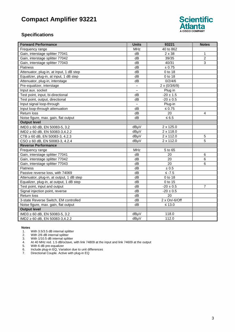
Forward Performance Units 93221 Notes Frequency range MHz 40 to 862
Gain, interstage splitter 77041 dB 2 x 38 1 Gain, interstage splitter 77042 dB 39/35 2 Gain, interstage splitter 77043 dB 40/31 3 Flatness dB ± 0.75 Attenuator, plug-in, at input, 1 dB step dB 0 to 18 Equalizer, plug-in, at input, 1 dB step dB 0 to 18 Attenuator, plug-in, interstage dB 0/2/4/6 Pre-equalizer, interstage − 2 x (0/3/6/9) Input aux. socket − Plug in Test point, input, bi-directional dB -20 ± 1.5 Test point, output, directional dB -20 ± 0.5 Input signal loop-through − Plug-in Input loop-through attenuation dB ≤ 0.75 Return loss dB 20 4 Noise figure, max. gain, flat output dB ≤ 6.5 Output level IMD3 ≥ 60 dB, EN 50083-5, 3.2 dBµV 2 x 125.0 IMD2 ≥ 60 dB, EN 50083-3,4.2.2 dBµV 2 x 118.0 CTB ≥ 60 dB, EN 50083-3, 4.2.3 dBµV 2 x 112.0 5 CSO ≥ 60 dB, EN 50083-3, 4.2.4 dBµV 2 x 112.0 5 Reverse Performance Frequency range MHz 5 to 65 Gain, interstage splitter 77041 dB 20 6 Gain, interstage splitter 77042 dB 20 6 Gain, interstage splitter 77043 dB 20 6 Flatness dB ± 0.5 Passive reverse loss, with 74069 dB ≤ -7.5 Attenuator, plug-in, at output, 1 dB step dB 0 to 18 Equalizer, plug-in, at output, 1 dB step dB 0 to 15 Test point, input and output dB -20 ± 0.5 7 Signal injection point, reverse dB -20 ± 0.5 Return loss dB 20 3-state Reverse Switch, EM controlled dB 2 x On/-6/Off Noise figure, max. gain, flat output dB ≤ 13.0 Output level IMD3 ≥ 60 dB, EN 50083-5, 3.2 dBµV 118.0 IMD2 ≥ 60 dB, EN 50083-3,4.2.2 dBµV 112.0
Notes 1. With 3.5/3.5 dB internal splitter 2. With 2/6 dB internal splitter 3. With 1/10.5 dB internal splitter 4. At 40 MHz red. 1.5 dB/octave, with link 74809 at the input and link 74609 at the output 5. With 6 dB pre-equalizer 6. Include plug-in EQ, Variation due to unit differences 7. Directional Couple. Active with plug-in EQ
Compact Amplifier 93221
4
Specifications, continued
General Performance Unit 93221 Notes Power supply 65 V coax line powering, rms, sine V AC 24 to 65 8 230 V mains line powering, rms, sine V AC 187 to 250 Power consumption, remote powered W 35.0 (38.0) 9 Power consumption, mains powered W 33.0 (36.0) 9 Max. current inputs and outputs A AC 7 Max. current, power insertion A AC 10 10 Hum Modulation at max. current, EN 50083-3 dB < -65 Transient protection kV, µs/µs 2, 1.2 / 50 Enclosure category − IP 66 Emission, EN 50083-2 dBpW < 20 Screening, EN 50083-2 dB < 85 Connectors − input and outputs (reduction) − Test points
−
PG 11 (5/8“) Female F-connector
Environmental
Operating temperature °C ˚ F
-20 to +55 -4 to 131
Mechanical
Housing Dimensions, W x H x D: mm in.
230 x 220 x 95 9.1 x 8.7 x 3.7
Packaging Dimensions, H x W x D mm in.
330 x 290 x 110 13.0 x 11.4 x 4.3
Material − Die-cast aluminium
Weight kg lbs
< 4.4 < 9.7
Notes: 8. A DC voltage supply is possible, 35 to 90 V DC 9. (...) with 3 dB compact transponder’s power consumption 10. external supply, remote powered type only
Housing
Note: Port thread: PG 11 Extra reduction rings for 5/8” thread are included in the delivery.
Compact Amplifier 93221
5
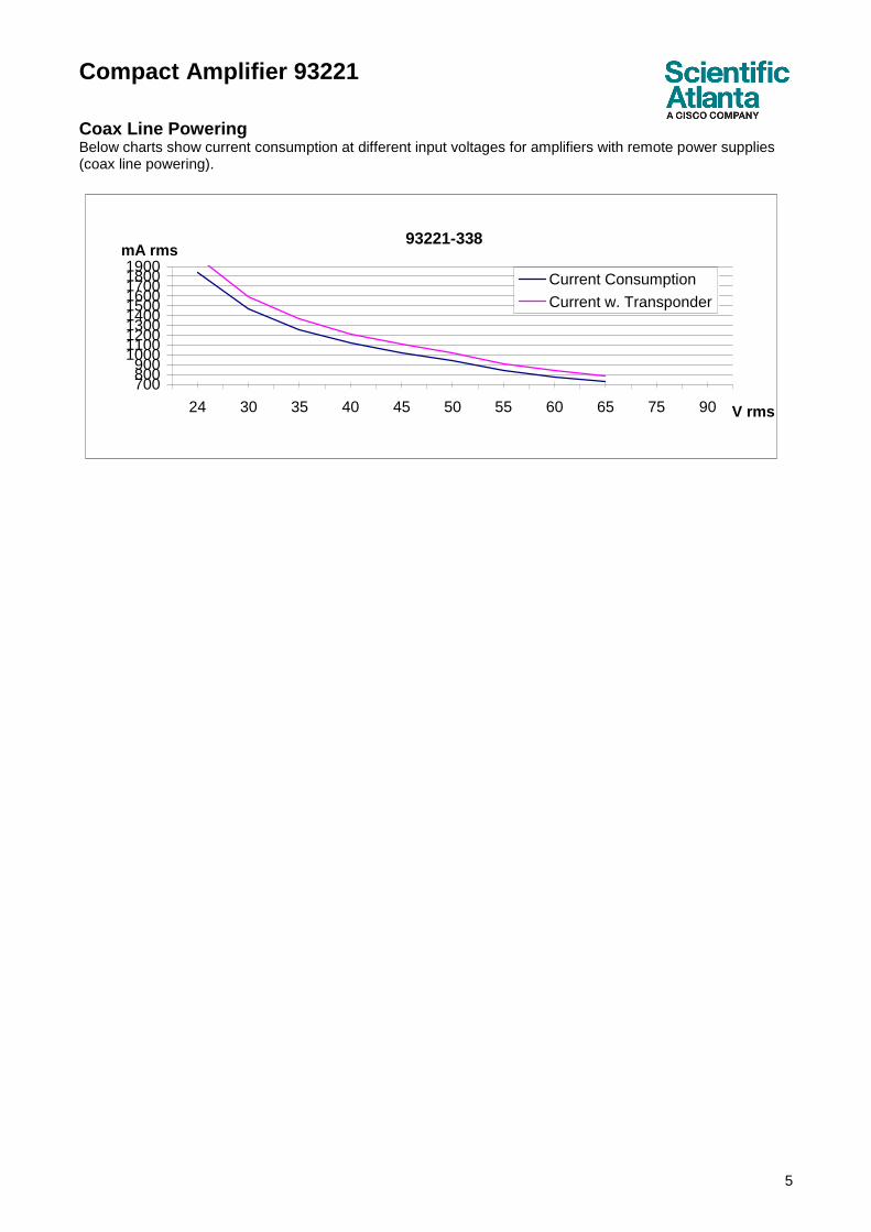
Coax Line Powering Below charts show current consumption at different input voltages for amplifiers with remote power supplies (coax line powering).
93221-338
700800900
1000110012001300140015001600170018001900
24 30 35 40 45 50 55 60 65 75 90 V rms
mA rms
Current Consumption
Current w. Transponder
Compact Amplifier 93221
6
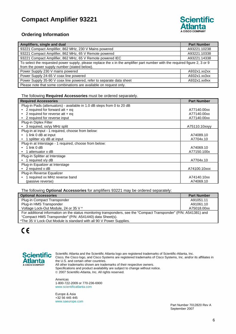
Ordering Information
Amplifiers, single and dual Part Number 93221 Compact Amplifier, 862 MHz, 230 V Mains powered A93221.10238 93221 Compact Amplifier, 862 MHz, 65 V Remote powered A93221.10338 93221 Compact Amplifier, 862 MHz, 65 V Remote powered IEC A93221.14338 To select the requested power supply, please replace the x in the amplifier part number with the required figure 2, 3 or 9 from the power supply number (stated below). Power Supply 230 V mains powered A932x1.xx2xx Power Supply 24-65 V coax line powered A932x1.xx3xx Power Supply 35-90 V coax line powered, refer to separate data sheet A932x1.xx9xx Please note that some combinations are available on request only.
The following Required Accessories must be ordered separately.
Required Accessories Part Number Plug-in Pads (attenuators) - available in 1.0 dB steps from 0 to 20 dB • 2 required for forward att + eq • 2 required for reverse att + eq • 2 required for reverse input
Plug-in at input - 1 required, choose from below: • 1 link 0 dB at input • 1 splitter x/y dB at input
A74089.10 A7704x.10
Plug-in at Interstage - 1 required, choose from below: • 1 link 0 dB • 1 attenuator x dB
A74069.10
A77150.100x Plug-in Splitter at Interstage • 1 required x/y dB
A7704x.10
Plug-in Equalizer at Interstage • 2 required x dB
A74100.10xxx
Plug-in Reverse Equalizer • 1 required xx MHz reverse band (passive reverse)
A74140.10xx A74069.10
The following Optional Accessories for amplifiers 93221 may be ordered separately:
Optional Accessories Part Number Plug-in Compact Transponder Plug-in HMS Transponder Voltage Lock-Out Module, 24 or 35 V *
A91051.11 A91061.10
A75018.00xx For additional information on the status monitoring transponders, see the “Compact Transponder” (P/N: A541381) and “Compact HMS Transponder” (P/N: A541440) data Sheet(s).
*The 35 V Lock-Out Module is standard with all 90 V Power Supplies.
Scientific Atlanta and the Scientific Atlanta logo are registered trademarks of Scientific-Atlanta, Inc. Cisco, the Cisco logo, and Cisco Systems are registered trademarks of Cisco Systems, Inc. and/or its affiliates in the U.S. and certain other countries. All other trademarks shown are trademarks of their respective owners. Specifications and product availability are subject to change without notice. 2007 Scientific-Atlanta, Inc. All rights reserved. Americas 1-800-722-2009 or 770-236-6900 www.scientificatlanta.com Europe & Asia +32 56 445 445 www.saeurope.com