72
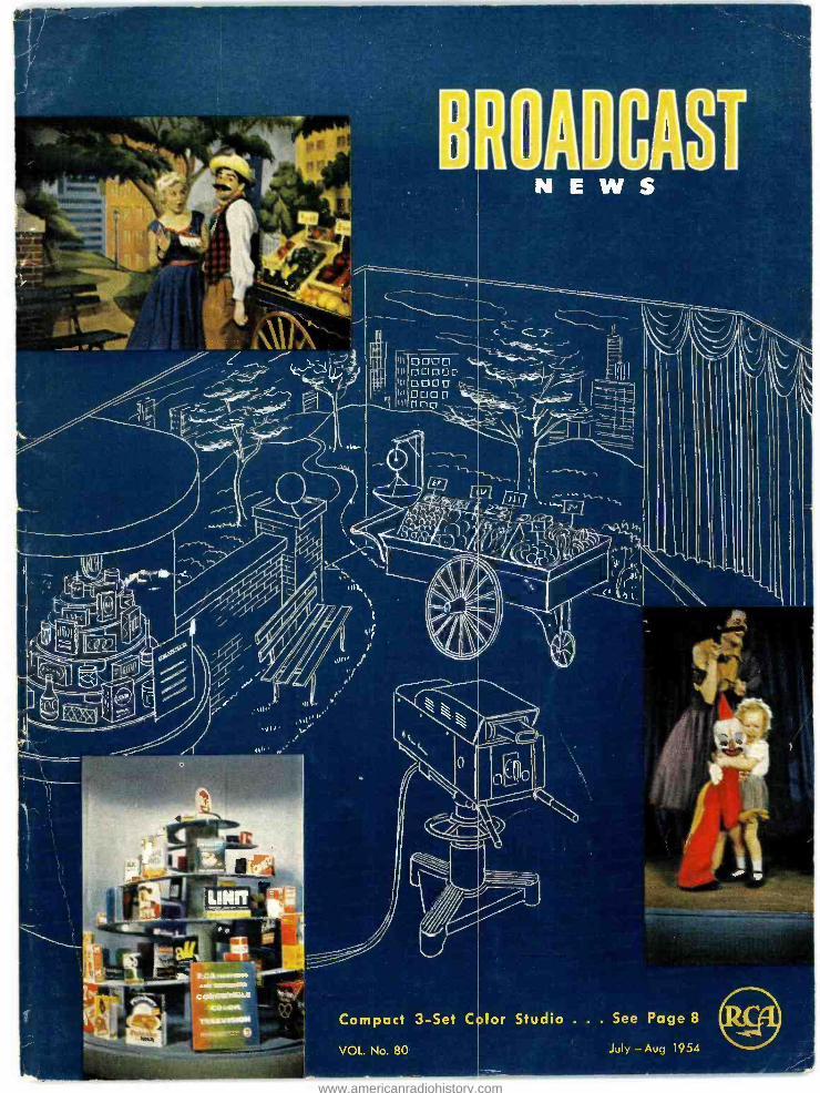
Compact 3 -Set C VOL. No. 80 for Studio . . . See Page 8 July - Aug 1954 www.americanradiohistory.com
Compact 3 -Set C
VOL. No. 80
for Studio . . . See Page 8
July - Aug 1954
www.americanradiohistory.com

"hide s behind
a ... hand
...corsage
... the new MK- 6A RCA dynamic miniature microphone Here's a miniature mike that does a man -size job ... This RCA Dynamic Microphone is small enough to conceal in a
man's hand or under his necktie. Ladies can hide it behind a corsage. Or, you can put it behind a table decoration. In any setting, it's an amazing help in keeping the informal atmos- phere so many television shows, interviews and public occasions require.
However you use it, you can be sure of correct speech quality. Low- pitched chest sounds, sibilants and high -pitched sounds arc all reproduced in proper balance.
Just three inches long, weighing only 5M ounces and neutral in color, this RCA Miniature is as inconspicuous as modern microphone design can make it. A small and very flexible cable allows free, easy movement by anyone using it. And in spite of its unusual compactness, the BK -6A is a high quality microphone and has very durable construction.
This RCA Miniature Dynamic Microphone can increase your staging and production flexibility in many ways. For infor- mation on all of its advantages ... contact your RCA Broadcast Sales Representative, or write Dept. G -129, RCA Engineering Products Division. In Canada, write RCA Victor Ltd., Montreal.
RADIO CORPORATION of AMERICA ENG INEER /NG PRODUCTS D /V /S /ON CAMDEN, N.J.
www.americanradiohistory.com
Vol. No. 80 July- August, 1954
BROADCAST NEWS published by
RADIO CORPORATION OF AMERICA ENGINEERING PRODUCTS DIVISION CAMDEN, NEW JERSEY
PRICE In continental U.S.A. - - - $4.00 for 12 issues
In other countries $5.00 for 12 issues
C O N T E N T S
COMPACT THREE -SET COLOR STUDIO . . . by M. G. Moon 8
WBRE -TV FIRST WITH RCA 12.5 KW UHF AMPLIFIER by Charles Sakoski 12
TRANSMITTER RELAY CONTROL SYSTEMS by Robert M. Crotinger 18
WEAU . . . RADIO -TV by T. O. Jorgenson 20
COLOR STRIPE ADDED TO STATIONS MONOCHROME SIGNAL by E. E. Gloystein 26
WTVR COMPLETES GIANT TOWER -MAXIMUM POWER by James W. Kyle 30
THE ETERNAL QUEST OF ELECTRONICS 34
RECENT BROADCAST SALES APPOINTMENTS 36
INSTALLING 4 RE- USARLE TV LIGHTING GRID AT KGO -TV by Edward B. Smith 38
RCA LEADS IN SAFETY, TOO by Ed Jones 40
ENGINEERING ASPECTS OF UHF BOOSTER INSTALLATION . . by less Epstein,
Wendell C. Morrison and O. M. Woodward, Jr. 42
COMMERCIAL ASPECTS OF UHF BOOSTER OPERATION by L. W. Haeseler,
N. McNaughten and L. J. Wolf 52
CLOSED -CIRCUIT TELEVISION UNLIMITED 55
"RCA PIONEERED AND DEVELOPED COMPATIBLE COLOR TELEVISION"
Copyright 1 ü5;. Kad;o Curpura( ion a1 d ,,eriea, Engineering Products Division, Camden, N.J.
www.americanradiohistory.com
C11511-KINItiVg'
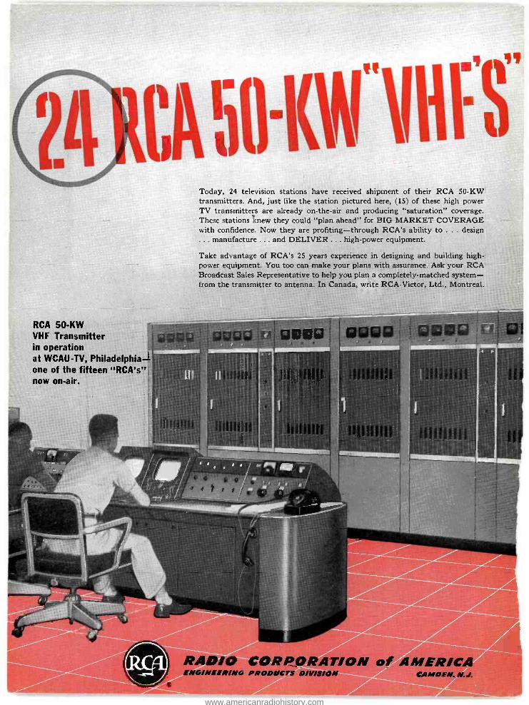
RCA 50 -KW VHF Transmitter in operation at WCAU -TV, Philadelphia R one of the fifteen "RCA's" now on -air.
Today, 24 television stations have received shipment of their RCA 50 -KW transmitters. And, just like the station pictured here, (15) of these high power TV transmitters are already on- the -air and producing "saturation" coverage. These stations knew they could "plan ahead" for BIG MARKET COVERAGE with confidence. Now they are profiting- through RCA's ability to ... design ... manufacture ... and DELIVER ... high -power equipment.
Take advantage of RCA's 25 years experience in designing and building high power equipment. You too can make your plans with assurance. Ask your RCA Broadcast Sales Representative to help you plan a completely- matched system - from the transmitter to antenna. In Canada, write RCA -Victor, Ltd., Montreal.
i a re
A1110 CORPORATION of AMERICA ENGINEER ING PRODUCTS DIVISION CAMDEN. N.J.
www.americanradiohistory.com

fl EIIiii:Ri:i1
Here's why RCA 50 -KW
transmitters are the
overwhelming choice:
RELIABLE RCA 50 -KW equipments are built to operate with "day -in day -out" reliability. (Ask the RCA -equipped 50 -KW VHF stations already on air.)
CONSERVATIVE DESIGN RCA 50 -KW VHF's deliver a full 50 kilowatts of peak visual power- measured at the out- put of the sideband filter. You get full power
output on both monochrome -AND COLOR, with power to spare!
SATURATION COVERAGE An RCA 50 -KW VHF, operated in conjunction with an RCA Superturnstile Antenna, is cap- able of "flooding" your service area with STRONG SIGNALS -close in and far out! With standard antennas, RCA 50 KW's can
develop 316 KW ERP -with power to spare.
AIR -COOLED RCA 50 -KW VHF's are all air -cooled. You
save on installation costs and maintenance. Visual and aural P.A.'s use conventional RCA
power tetrodes (Type 6166).
MATCHED DESIGN RCA 50 -KW VHF's are "systems- matched" to deliver peak performance in combination with RCA 50 -KW antenna systems.
COMPLETE SYSTEM RCA supplies everything in system equip-
ment to match the RCA "50 -KW" precisely; antenna, transmission line, fittings, tower, r -f loads, diplexers--and all other components needed to put a 50 -KW VHF signal on the air.
SERVICE RCA TV transmitter operation is backed up
by a nationally famous broadcast engineer- ing service organization and an RCA replace-
ment parts service.
CA PIONEERED AND DEVELOPED
COMPATIBLE COLOR TIVISION.
"Who's Who" List of RCA "50's"
KAKE-TV
KLZ-TV
KMBC-TV
KOLN-TV
KTLJ
KWTV
WAAM -TV
WBAL-TV
WBTW
WCAU-TV
WCHS-TV
WGAL-TV
WMIN-TV/
WHBQ-TV
WHO-TV
WISH-TV
WJAR-TV
WJRT
WNHC-TV
WOOD-TV
WSFA-TV
WTHI-TV
WTOP-TV
WTRF-TV
WTCN-TV
50 -KW VHF Power Amplifiers at WCAU -TV. Air -cooled throughout.
I
www.americanradiohistory.com

IMO aMil 00013 ' 1+i®0111i 0000
J+lálaJif
1
RCA I2.5 -KW UHF Transmitter type TTU -I2A
O 12.5 -KW UHF Power Available
W ith RCA's newtrans- mitter, you get full 12 y - kilowatt output (at the low end of the band). Moreover, you get this with all ad- justments made for optimum color trans- mission -and with an extra -large allowance (10 %) for losses in the Filterplexer. In most cases, loss is actually much less, so that output on some channels is nearly 14 KW.
so\:a1\I1 ar_'N i
\aNaaaa N em,...a.T.....,.,T.. BNMnYO. fRB1aBBN88\i5N888
\NNaa MC7CiIL:7L'G71G7 - L;I1G1 -°
O 300 -KW to 500 -KW Effective Radiated Power (ERP)
Operated in combination with a non -directional RCA high - gain UHF Pylon Antenna, this 12.5 -KW transmitter is capable of providing an ERP of 300 KW. With a directional RCA Pylon Antenna, powers up to 500 KW are possible (in a given direction).
Q Designed for Color Performance requirements for color are much more strin- gent than for monochrome. The TTU -12A was designed to meet color requirements. Over -all linearity is virtually a straight line -from white level to sync signal peaks. Wide band width provides excellent response out to 4.2 MC. And the very important phase vs. amplitude response is constant over the whole operating range.
Curve illustrating the linearity characteristic of the RCA TTU - 12A transmitter.
A linearity trace (taken direct- ly from an oscilloscope) of the TTU -12A transmitter at 12 KW "peak -of- sync."
Another linearity trace (taken directly from an oscilloscope) of the TTU -1B when driving the TTU -I2A to 12 KW "peak -of- sync." "P.A." output.
'lg.'''. a,m
PEDESTAL LEVEL
Se11111minimow
VMITE
=i =CG =m: : HEIMitigaufu a... inotan ammo FrammosmEN 1a111111111111111li111
Level TUNE 0 GAMMA
¡WE
r..
r.-
i
O Unsurpassed Monochrome Quality
Tralu 1rM.awtas
novas swoHa os
W A.w.f. r.ew. Ca.) f I I
io .o ge j
to I
4 --I i I.-TV CMAHHfI LI,IIif--{
+tY
-240
Equally important -you get SUPER MONOCHROME. QUALITY with this RCA UHF transmitter. It exceeds FCC require- ments for satisfactory monochrome operation by a wide margin! Since the RCA transmitter is adjusted for the more stringent color requirements, it is particularly good for monochrome.
© Conventional Tubes Throughout The latest circuit principles and techniques are employed in the TTU -12A -but they are easily un- derstood by all station operators. That's because only conventional type tubes are used. For example, the RCA - developed high -power tetrode (RCA -6448) is used in both aural and visual "P.A.'s ". This tube is small and easy to
handle -fits into a unique "glide -in" cavity assembly that can be interchanged quickly and easily. The result is a high - power UHF transmitter that is as simple, reliable, and con- venient to operate as standard broadcast transmitters.
O Economical To Operate Average power consumption of the TTU -I2A is less than other UHF transmitters of equivalent power. Tubes are designed for long operating life. At conservative estimates, these provide total savings up to $34,000 -based on a 10- year operation. See the typical readings and performance characteristics in Table I.
TABLE I
(Typical Transmitter Specifications and Meter Readings) Transmitter Power Consumption (approx.):
Average Picture 85 KW Power Factor o 9
Transmitter Output Meter Readings: Peak of Sync Aural (C.W.) Power Output (transmitter) 14.0 KW 8.4 KW Power Output (Filterplexer) 12.6 KW 7.6 KW Plate Efficiency 47.6% 33 3%
Transmitter Overall Dimensions: Width (front line cabinets) 235" Height 84" Depth 32- 9/16" Weight 6000 lbs. (approx.)
www.americanradiohistory.com

ï
7 n
s.
:.
ORION Rs ISKONF" hasaHbeffbtureL1
O RCA I -KW Driver-Plenty of Reserve The RCA 12.5 -KW UHF transmitter uses the famous RCA TTU -1B i -KW UHF transmitter as the driver. This trans- mitter, now used by nearly a hundred UHF stations, has established an outstanding record for performance and reliability. If you want to begin UHF operations with one kilowatt now, you can do so with an RCA TTU -1B 1 -KW transmitter. Then add an RCA 12.5 -KW UHF power am- plifier later.
O Space- Saving Mechanical Features
Horizontally sliding doors, front and back, save on work- able floor space -give the oper- ators more elbow room. Small cubicles (27' wide, 32' deep, 84' high) enable you to move them through standard door- ways and in and out of standard elevators. Pre- formed inter - cabinet connecting cables re- duce installation costs.
10 Micro - Second, Fault- Protection Unique electronic overload protection completely safe- guards power tubes and circuitry against momentary or sustained overload. (For example, the protection circuit will remove power so fast it will prevent damage to a wire as fine as 0.005 -inch diameter shorted across the 7000 -volt power supply!)
Hi -Lo Cutback Reduces "Off -Air" Time With the TTU -12A transmitter you can cut back to a generous 1 -KW power level - and stay "on -air" while making emergency repairs to the 12 A -KW amplifier. More- over, small size tube cavities in the power amplifiers may be interchanged in less than 5 minutes - enabling you to return to full power promptly.
RCA TTU -12A Filterplexer
m You Pay Nothing for `[Extras" The price of the RCA 12.5 -KW UHF includes the complete transmitter package. No "extra" charge for UHF Filter - plexer (combination sideband filter and diplexer). No "extra" charge for one complete set of tubes. No "extra" charge for two sets of crystals, two P.A. "glide -in" cavity
AP dollies, one spare cavity, two water pumps, and pyranol- filled plate transformer.
Specify a Completely Matched UHF System
RCA can supply a completely matched system to meet any station requirement. This includes the an- tenna and tower, transmitter, console, monitoring equipment, transmission line or waveguide,
and the many other accessories needed to put a UHF station on the air. Everything is RCA UHF matched for peak performance and you get Waveguide everything from one reliable source -RCA! Section
For complete Information on the RCA 12.5 -KW UHF transmitter -and RCA UHF accessories -call your RCA Broadcast Sales Representative.
New brochure on the RCA 12.5 - KW UHF transmitter. Includes technical specifications, floor plans. Free from your RCA
Broadcast Sales Representative.
RCA PIONEERED AND DEVELOPED COMPATIBLE COLOR TELEVISION
RADIO CORPORATION of AMERICA ENGINEERING PRODUCTS DIVISION CAMDEN, N.J.
www.americanradiohistory.com

BQ -1A TURNTABLE. For fine -groove 45's and 33'3 LP's (exclusively) -up to 12 ". Only 28" high, 20" wide, 16',2" deep, this studio - proved unit is your answer for a moderately priced turntable. Complete, with lightweight tone arm, filter, 1.0 mil pick -up, and cabinet.
BQ -70F DELUXE, 3 -SPEED TURNTABLE. Newest edition of RCA's famous 70- series transcrip- tion turntables. Photo shows installation of Universal Tone Arm for Vertical and Lateral standard groove transcriptions and a light- weight tone arm for 45 and 331/3 fine- groove recordings.
BC -4A AUDIO CONTROL. This new unit pro- vides adequate control and switching for one studio, control booth, two turntables, net- work, 2 remotes, and tape recorder. Addition of a second BC -4A doubles facilities, permits dual- channel operation. Ideal audio sub - control for TV stations.
Pictured on these pages are just a few of the units - from the most complete line of professional audio
equipment for AM, FM and Television.
Application- engineered to fit every Broadcast audio
pick -up and reproduction situation in the station, this
comprehensive line includes...microphones and micro-
phone accessories...turntables...tape recorders...am-
plifiers... loudspeakers ...custom -built equipment... plus
hundreds of other audio items needed to meet each
and every station requirement.
RCA audio equipment is imaginatively designed to
exceed present -day station requirements- competi-
tively. It makes possible new techniques in program
handling - offers a new basic approach to greater
operation economy. Ask your RCA Broadcast Sales
Representative for complete technical information. In
Canada, write RCA Victor, Ltd., Montreal.
BC -2B STUDIO CONSOLETTE. "Low -boy" console offers deluxe, operation -proved features usually found in custom -built equipment -but at a standard "package" price. Includes complete high -fidelity speech input provisions for 2 studios, announce booth, 2 turntables, 5 remotes, and network.
BCM -1A AUXILIARY MIXER CONSOLE. For large AM and TV
studios. It triples the microphone inputs of the BC -2B -up to 16 microphones can be connected -8 can be used simultaneously. Enables you to "block- build" os required.
www.americanradiohistory.com
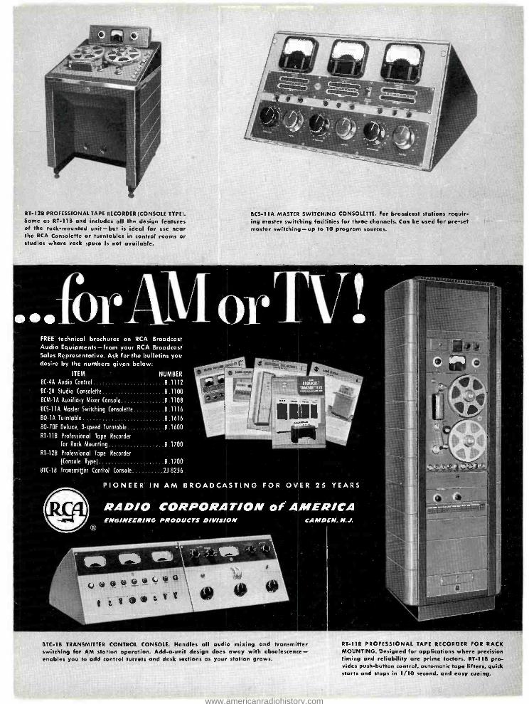
RT -128 PROFESSIONAL TAPE RECORDER (CONSOLE TYPE;. Same as RT -11B and includes all the design features of the rack -mounted unit -but is ideal for use near the RCA Consolette or turntables in control rooms or studios where rack space is not available.
BCS -11A MASTER SWITCHING CONSOLETTE. For broadcast stations requir- ing master switching facilities for three channels. Con be used for pre -set master switching -up to 10 program sources.
FREE technical brochures on RCA Broadcast Audio Equipments -from your RCA Broadcast Sales Representative. Ask for the bulletins you desire by the numbers given below:
ITEM NUMBER
BC -4A Audio Control B 1112
BC -2B Studio Consolette B 1100
BCM -1A Auxiliary Mixer Console B 1108
B(S -11A Master Switching Consolette B 1116
BQ -1A Turntable B 1616
B0 -70F Deluxe, 3 -speed Turntable 8.1600
RT -11B Professional Tape Recorder
for Rack Mounting B 1700
RT -12B Professional Tope Recorder
(Console Type) B 1700
BT( -1B Transmitter Control Console 218256
PIONEER IN AM BROADCASTING FOR OVER 25 YEARS
ENGINEERING PRODUCTS DIVISION CAMDEN, N.J.
(0Q6Ip e I 41)YY
BTC -1B TRANSMITTER CONTROL CONSOLE. Handles all audio mixing and transmitter switching for AM station operation. Add -a -unit design does away with obsolescence - enables you to add control turrets and desk sections as your station grows.
RT -118 PROFESSIONAL TAPE RECORDER FOR RACK MOUNTING. Designed for applications where precision timing and reliability are prime factors. RT -11B pro- vides push -button control, automatic tape lifters, quick starts and stops in 1/10 second, and easy cueing.
www.americanradiohistory.com
COMPACT THREE -SET COLOR STUDIO
... Occupies Only 22' x 23' Area
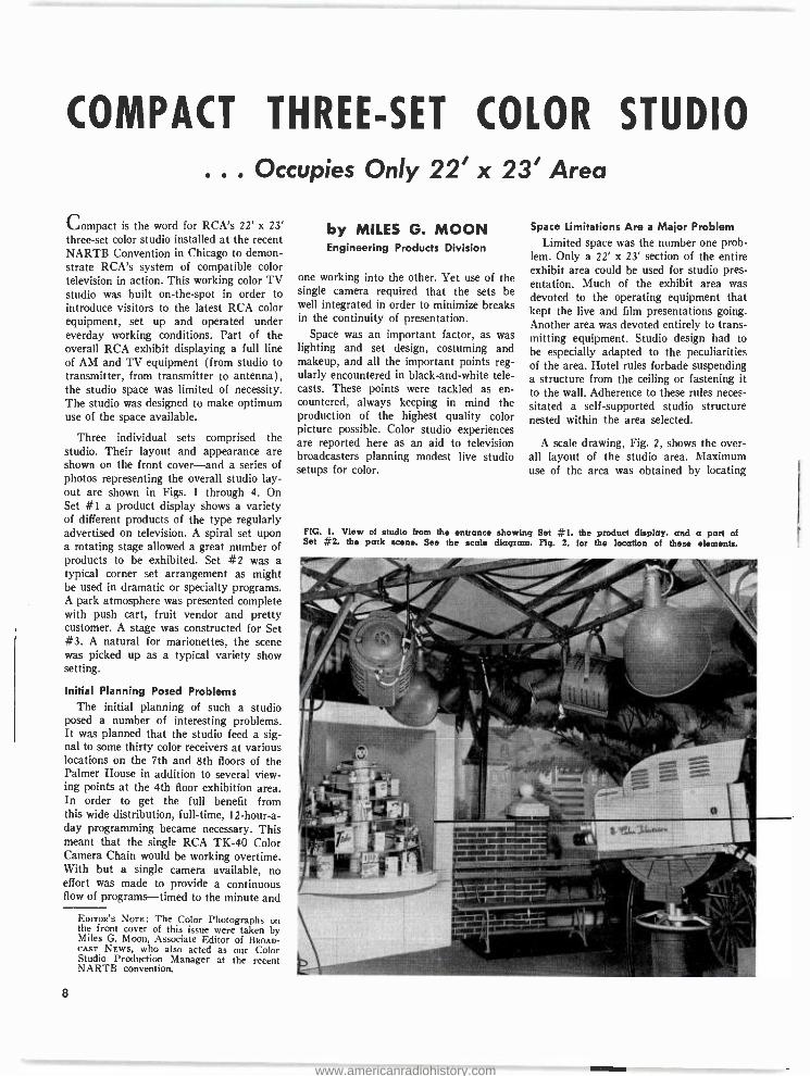
Compact is the word for RCA's 22' x 23' three -set color studio installed at the recent NARTB Convention in Chicago to demon- strate RCA's system of compatible color television inaction. This working color TV studio was built on- the -spot in order to introduce visitors to the latest RCA color equipment, set up and operated under everday working conditions. Part of the overall RCA exhibit displaying a full line of AM and TV equipment (from studio to transmitter, from transmitter to antenna), the studio space was limited of necessity. The studio was designed to make optimum use of the space available.
Three individual sets comprised the studio. Their layout and appearance are shown on the front cover -and a series of photos representing the overall studio lay- out are shown in Figs. 1 through 4. On Set #1 a product display shows a variety of different products of the type regularly advertised on television. A spiral set upon a rotating stage allowed a great number of products to be exhibited. Set #2 was a typical corner set arrangement as might be used in dramatic or specialty programs. A park atmosphere was presented complete with push cart, fruit vendor and pretty customer. A stage was constructed for Set #3. A natural for marionettes, the scene was picked up as a typical variety show setting.
Initial Planning Posed Problems The initial planning of such a studio
posed a number of interesting problems. It was planned that the studio feed a sig- nal to some thirty color receivers at various locations on the 7th and 8th floors of the Palmer House in addition to several view- ing points at the 4th floor exhibition area. In order to get the full benefit from this wide distribution, full -time, I2- hour -a- day programming became necessary. This meant that the single RCA TK -40 Color Camera Chain would be working overtime. With but a single camera available, no effort was made to provide a continuous flow of programs -timed to the minute and
EDITOR'S NOTE: The Color Photographs on the front cover of this issue were taken by Miles G. Moon, Associate Editor of BROAD- CAST NEWS, who also acted as our Color Studio Production Manager at the recent NARTB convention.
8
by MILES G. MOON Engineering Products Division
one working into the other. Yet use of the single camera required that the sets be well integrated in order to minimize breaks in the continuity of presentation.
Space was an important factor, as was lighting and set design, costuming and makeup, and all the important points reg- ularly encountered in black- and -white tele- casts. These points were tackled as en- countered, always keeping in mind the production of the highest quality color picture possible. Color studio experiences are reported here as an aid to television broadcasters planning modest live studio setups for color.
Space Limitations Are a Major Problem
Limited space was the number one prob- lem. Only a 22' x 23' section of the entire exhibit area could be used for studio pres- entation. Much of the exhibit area was devoted to the operating equipment that kept the live and film presentations going. Another area was devoted entirely to trans- mitting equipment. Studio design had to be especially adapted to the peculiarities of the area. Hotel rules forbade suspending a structure from the ceiling or fastening it to the wall. Adherence to these rules neces- sitated a self- supported studio structure nested within the area selected.
A scale drawing, Fig. 2, shows the over- all layout of the studio area. Maximum use of the arca was obtained by locating
FIG. 1. View of studio from the entrance showing Set 1, the product display, and a pari of Set #2, the park scene. See the scab diagram, Fig. 2, for the location of these elements.
www.americanradiohistory.com
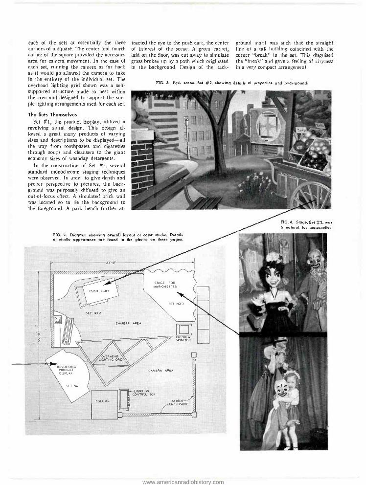
each of the sets at essentially the three corners of a square. The center and fourth corner of the square provided the necessary area for camera movement. In the case of each set, running the camera as far back as it would go allowed the camera to take in the entirety of the individual set. The overhead lighting grid shown was a self - supported structure made to nest within the area and designed to support the sim- ple lighting arrangements used for each set.
The Sets Themselves
Set #1, the product display, utilized a revolving spiral design. This design al- lowed a great many products of varying sizes and descriptions to be displayed -all the way from toothpastes and cigarettes through soups and cleansers to the giant economy sizes of washday detergents.
In the construction of Set #2, several standard monochrome staging techniques were observed. In order to give depth and proper perspective to pictures, the back- ground was purposely diffused to give an out-of -focus effect. A simulated brick wall was located so to tie the background to the foreground. A park bench further at-
tracted the eye to the push cart, the center of interest of the scene. A green carpet, laid on the floor, was cut away to simulate grass broken up by a path which originated in the background. Design of the back-
ground motif was such that the straight line of a tall building coincided with the corner "break" in the set. This disguised the "break" and gave a feeling of airyness in a very compact arrangement.
FIG. 3. Park scene, Set =2, showing details of properties and background.
- - Nos
FIG. 4. Stage. Set = 3, was a natural for marionettes.
FIG. 2. Diagram showing overall layout of color studio. Details of studio appearance are found in the photos on these pages.
%/////////////////JXOOi/a///////////'í//i
STAGE FOR MARIONETTES
SET NO 3
SET NO 2
CAMERA AREA.
PREVIEW MONITOR
COLUMN
CAMERA AREA
- LIGHTING CONTROL BOX
STUDIO ENCLOSURE
www.americanradiohistory.com

1.tto IMM t o . MINIMMIIL.1
FIG. 5. Control center for the entre exhibit. All operative equipment was controlled from this point- 3Vidlcon Color Film Chain, Monochrome Vidicon Film Chain, Color Studio Camera and complete audio and video switching for various viewing locations throughout the exhibit area and other points in hotel.
Some special color considerations were necessary. The background was painted in pastel or neutral shades of gray, green, orange and brown. These were the colors in the medium range of reflectance. Highly reflective colors as well as highly absorb - tive colors were carefully avoided. The background motif was purposely kept sim- ple and subdued so that it did not compete with the action in either design or color.
The stage, Set #3 was the simplest of the three sets. Essentially a triangle, 8 feet on each side, it was built up 20 inches from the floor to give the best viewing angle on the night -club size marionettes. The stage front was painted light blue to match the
10
curtains used for background. Curtains were used for simplicity as well as to give airyness to an otherwise cramped corner. A preview monitor was located on a plat- form, stage left, so the performer could keep a check on the antics of her mario- nette family.
Lighting Arranged to Fit Conditions
Space limitations necessitated some de- partures from standard lighting practices - effects lighting was impractical and back lighting had to be kept to a minimum. Freedom of movement and versatility of presentation were most important for there was little rehearsal. Hence even lighting
was the main consideration. Photos, Figs. 6 and 7, were taken by the existing studio light and show the low lighting ratio on the sets. Here's how the required studio lighting, tailored to the circumstances was achieved.
Scoops were used here as the main source of lighting in order to hold down dark shadows and multiple shadows on the background. Spotlights used were placed far enough from performers to avoid heavy shadows, yet still supply interesting high- lights. Floor scoops proved to be a very useful tool since they can be moved from set to set as needs occur. A portable light- ing control box was located at the rear of
www.americanradiohistory.com

the camera area. From this location it was possible for the operator to view all three sets. The box was set up on three main cir- cuits, one for each set. This eliminated having to hunt and guess and cross patch in moving from one set to another.
The following is a list of the fixtures that were required for each of the sets: light intensities varied with circumstances: good color pictures were obtained at levels anywhere from 225 to 400 foot candles.
Set #1, product display:
1 Floor Scoop 1000 watts 1 Overhead Scoop 2000 watts
Set #2, park area:
2 Overhead Scoops 2000 watts 1 Spotlight 1000 watts 1 Baby Spot (for back-
light) 500 watts 1 Floor Scoop 1000 watts
Set #3, stage:
1 Spotlight 1000 watts
1 Overhead Scoop 2000 watts I Floor Scoop 1000 watts 1 Baby Spot (for back-
light) 500 watts
You'll notice on comparison with Set #2, Set #3 seems to be overlighted. Move- ment of marionettes over a relatively large stage area, required maximum light so the camera could be "irised down" for max- imum depth of focus. In this manner the cameraman was freed from constant focusing.
Normal Makeup and Costuming Techniques Used
Three different complexion types of girls were used -a blonde, brunette and red- head. Each of the girls used normal street makeup in good taste and very accept- able results were achieved without special makeup considerations. The man used a light talc to cut down glare. Faces of the marionettes were grayed down to appear as white. Products also received a "make- up" treatment. They were sprayed down to avoid glare. In some cases it may be necessary to "touch up" products to be dis- played much as would be required for four color magazine reproduction. However, in this case, it was not required.
Appropriate costumes were selected - avoiding white or almost white colors as well as very dark colors, navy blue, deep reds, etc. A look at the front cover will reveal costume coloring in the case of Sets #2 and #3.
FIG. 6. Lighting on the sets was kept evenly balanced. This photo taken by existing studio
light shows the low lighting ratio.
Camera Virtually Ran By Itself In station use, an operator would nor-
mally spend full time at the camera con- trols. At the convention a man was assigned
to camera control, however, his duties also included answering customer inquiries, op- erating the switcher which sent the color signals to the various viewing locations, riding audio, and serving as all purpose control room trouble shooter and guide. Many of the men assigned had their first experiences at the camera and the camera control position. The stability and sim- plicity of operation in the camera chain offset this otherwise burdensome handicap. Once the chain had been set up, only two operating controls were needed: (1) Re- mote Iris Control used as a master gain control and (2) Master Pedestal Control which causes all three pedestals to track up and down together.
Day to Day Operation Eight o'clock each morning the camera
was turned on. After only a half hour warm up period, the chain was checked out and set up for the nine o'clock show. Some time after lunch, essentially the mid- point of the operating day, the camera was checked for registration and color balance. RMA Standard Test Charts and a ruled grid pattern was used to check registration and a gray scale chart to check color bal- ance. Controls were touched up when neces- sary. The end of the operating day came at 9 P.M. The chain had been working overtime and had another full day of oper- ation ahead of it.
FIG. 7. Highest light levels were used on the stage. Movement of marion- ettes (for example the skating bear shown here) required high light levels so that the camera could be "irised down - for maximum depth of field.
11
www.americanradiohistory.com
u6i1 c C® QQ OC ... v 4
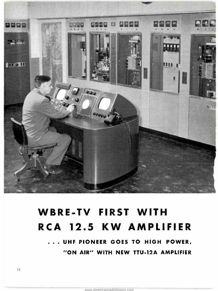
WBRE -TV FIRST WITH RCA 12.5 KW AMPLIFIER
. . . UHF PIONEER GOES TO HIGH POWER,
"ON AIR" WITH NEW TTU -12A AMPLIFIER
12
www.americanradiohistory.com
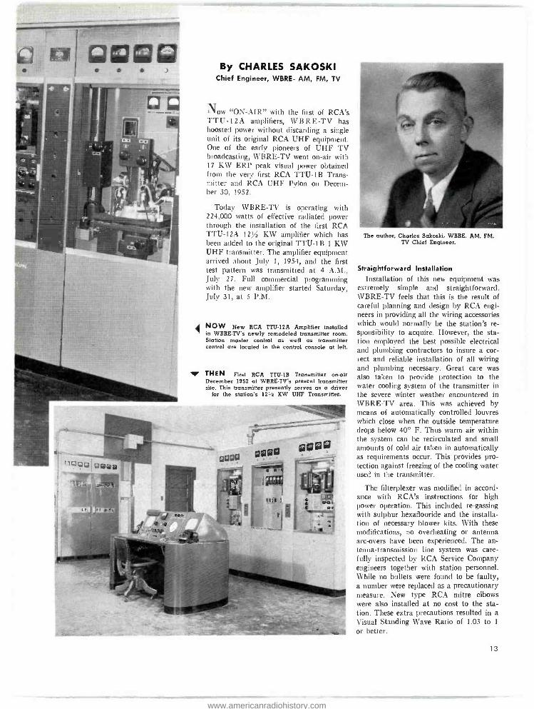
By CHARLES SAKOSKI Chief Engineer, WBRE -AM, FM, TV
Now "ON -AIR" with the first of RCA's TTU -12A amplifiers, WBRE -TV has boosted power without discarding a single unit of its original RCA UHF equipment. One of the early pioneers of UHF TV broadcasting, WBRE -TV went on -air with 17 KW ERP peak visual power obtained from the very first RCA TTU -1B Trans- mitter and RCA UHF Pylon on Decem- ber 30, 1952.
Today WBRE -TV is operating with 224,000 watts of effective radiated power through the installation of the first RCA TTU -12A 12x2 KW amplifier which has been added to the original TTU -1B 1 KW UHF transmitter. The amplifier equipment arrived about July 1, 1954, and the first test pattern was transmitted at 4 A.M., July 27. Full commercial programming with the new amplifier started Saturday, July 31, at 5 P.M.
NOW New RCA TTU -I2A Amplifier installed in WBRE -TV's newly remodeled transmitter room. Station master control as well as transmitter control are located in the control console at left.
THEN First RCA TTU -1B Transmitter on -air December 1952 at WBRE -TV's present transmitter site. This transmitter presently serves as a driver
for the station's 121/2 KW UHF Transmitter.
The author, Charles Sakoski, WBRE, AM, FM, TV Chief Engineer.
Straightforward Installation Installation of this new equipment was
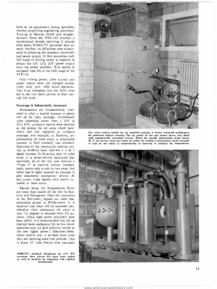
extremely simple and straightforward. WBRE -TV feels that this is the result of careful planning and design by RCA engi- neers in providing all the wiring accessories which would normally be the station's re- sponsibility to acquire. However, the sta- tion employed the best possible electrical and plumbing contractors to insure a cor- rect and reliable installation of all wiring and plumbing necessary. Great care was also taken to provide protection to the water cooling system of the transmitter in the severe winter weather encountered in WBRE -TV area. This was achieved by means of automatically controlled louvres which close when the outside temperature drops below 40° F. Thus warm air within the system can be recirculated and small amounts of cold air taken in automatically as requirements occur. This provides pro- tection against freezing of the cooling water used in the transmitter.
The filterplexer was modified in accord- ance with RCA's instructions for high power operation. This included re- gassing with sulphur hexaflouride and the installa- tion of necessary blower kits. With these modifications, no overheating or antenna arc -overs have been experienced. The an- tenna- transmission line system was care- fully inspected by RCA Service Company engineers together with station personnel. While no bullets were found to be faulty, a number were replaced as a precautionary measure. New type RCA mitre elbows were also installed at no cost to the sta- tion. These extra precautions resulted in a Visual Standing Wave Ratio of 1.03 to 1
or better.
13
www.americanradiohistory.com
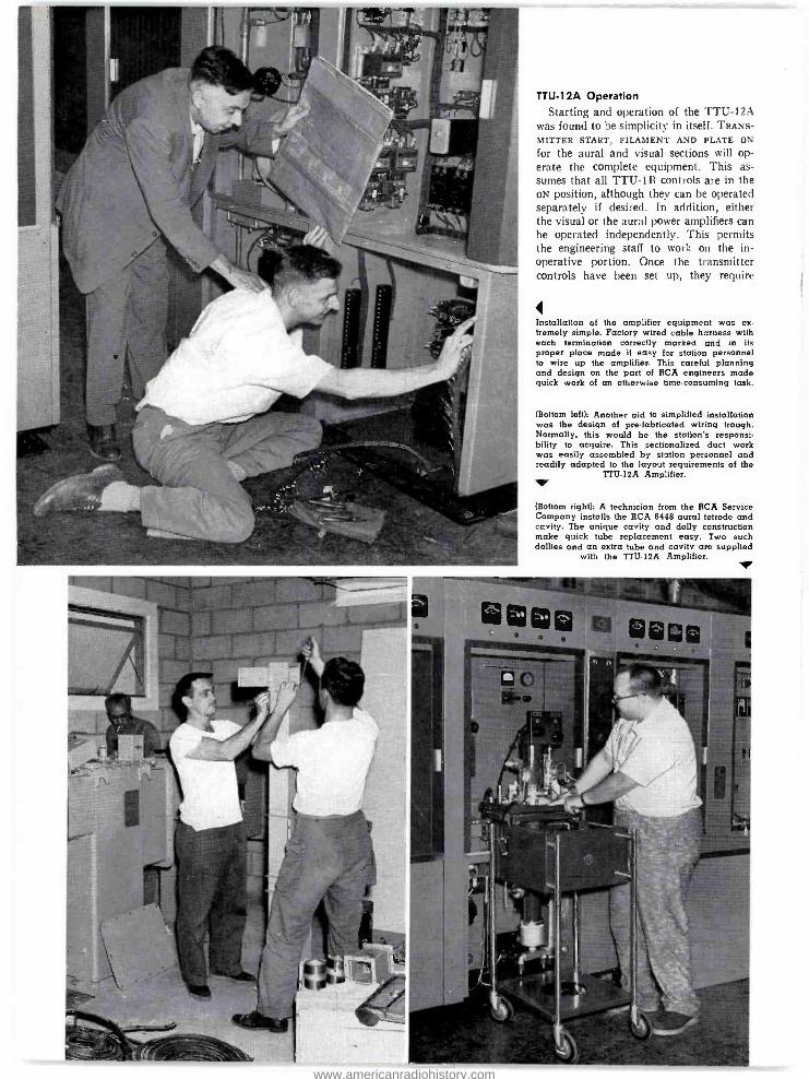
TTU -12A Operation Starting and operation of the TTU -12A
was found to be simplicity in itself. TRANS-
MITTER START, FILAMENT AND PLATE ON
for the aural and visual sections will op- erate the complete equipment. This as- sumes that all TTU -1B controls are in the ON position, although they can be operated separately if desired. In addition, either the visual or the aural power amplifiers can be operated independently. This permits the engineering staff to work on the in- operative portion. Once the transmitter controls have been set up, they require
Installation of the amplifier equipment was ex- tremely simple. Factory wired cable harness with each termination correctly marked and in its proper place made it easy for station personnel to wire up the amplifier. This careful planning and design on the part of RCA engineers made quick work of an otherwise time -consuming task.
(Bottom left): Another aid to simplified installation was the design of pre -fabricated wiring trough. Normally, this would be the station's responsi- bility to acquire. This sectionalized duct work was easily assembled by station personnel and readily adapted to the layout requirements of the
TTU -12A Amplifier.
(Bottom right': A technician from the RCA Service Company installs the RCA 6448 aural tetrode and cavity. The unique cavity and dolly construction make quick tube replacement easy. Two such dollies and an extra tube and cavity are supplied
with the TTU 12A Amplifier.
www.americanradiohistory.com
little or no adjustment during operation, thereby simplifying engineering operations. Tune -up is likewise simple and straight- forward. Since the TTU -12A employs a conventional tetrode, operating in circuits with which WBRE -TV personnel were al- ready familiar, no difficulties were encoun- tered in obtaining the necessary bandwidth and power output. In this connection only 700 watts of driving power is required to obtain the full 12/ KW power output from the power amplifier. This results in increased tube life in the 6181 stage of the TTU -1 B.
Grid driving power, plate current and power output have not changed percep- tively after over 1000 hours operation. This is an indication that the 6448 tubes are in the very early portion of their nor- mal life cycle.
Coverage Is Substantially Increased
Broadcasters are fundamentally inter- ested in what a sizable increase in power will do for their coverage. Immediately upon increasing power from 1 KW to 12/ KW, numerous reports were received at the station for all areas which here- tofore had had negligible or mediocre coverage. For example, in Sunbury, ap- proximately 60 miles away, a remarkable increase in field intensity was achieved. Operators of the community antenna sys- tem in Sunbury have reported a 3 to 1
signal increase. In Scranton, only 18 miles away, it is conservatively estimated that essentially all of the city now receives a "Class A" or superior picture. Interest- ingly, points only a mile or two away, but below line of sight, received an increase to give completely satisfactory service. At low power, these signals were nearly un- usable in these areas.
Signals along the Susquehanna River are more than usable all the way to Sun- bury and Selinsgrove. Over the mountains to the Northwest, signals are more than acceptable almost to Williamsport. It is expected that these will be improved con- siderably when mechanical tilt which is now 1/ degrees is removed from the an- tenna. (Once high power amplifiers have been added, it is recommended that tilt be checked since mechanical tilt for low power operation may not give optimum results at the new higher power.) Allentown -Beth- lehem reports that in at least some areas they are receiving snow -free pictures. This is about 55 miles distant over mountain
WBRE -TV's modified filterplexer for 12' 2 KW operation. New blower kits have been added as well as facilities for regassing with sulphur
hexafluoride.
The water cooling system for the amplifier includes a station designed modification for protection against freezing. The air intake on the unit shown above was fitted with automatically controlled louvres. When the outside temperature drops below 40° F, the louvres close and warm air within the system is recirculated. Small amounts of cold air are taken in automatically at intervals to stabilize the temperature.
15
www.americanradiohistory.com

ranges. Binghamton, 68 miles air distance, also reports reception.
The Pimple Hill Relay Station
Lacking network feed available to most other stations, WBRE -TV was faced with the problem of constructing the Pimple Hill Relay Station. Field intensity meas- urements and reliability tests on Channel 4, New York City had been conducted from as early as 1947 when WBRE first contemplated entering television. With this information at hand the Pimple Hill relay station was readily constructed to provide WBRE -TV with NBC programs direct from WNBT, New York City.
This careful planning and investigation over a long period of time has paid off many times. For example, there was the time when a combined wind and ice storm destroyed the complete receiving antenna system. Had it not been for the foresight of providing for off air pickup at the trans- mitter site, this might have resulted in the loss of many hours of valuable air time. In this case the rhombic receiving antennas were coated with four inches of radial ice, and strong winds knocked the antennas from their supporting structure. Anyone contemplating the installation of a pickup and relay station of this type would be well advised to have a standby installation. In addition, it was found that wooden sup- porting poles as well as corrosion free guy wires are extremely important. Rust pro- duced at the junction of a metallic pole and a non -galvanized guy wire might easily
Shadowgraph of WBRE -TV area. Prepared during the early planning stages, the map shows those areas in which hills and peaks have obstructed line of sight. Depth of the shadows have been computed. Mail reports indi- cate that with increase in transmitter power much of the shadow area up to 200 feet below line of sight in Scran- ton and Wilkes -Barre now receive acceptable signals.
WBRE -TV Transmitter Site. The housing on top of the transmitter building holds microwave relay receivers for both the studio -to- transmitter link and the inter -city relay link. Telephone poles in the background hold rhombic an- tenna for direct pickup of WNBT, New York, 100 miles
air distance.
16
www.americanradiohistory.com

Closeup of relay transmitter housing at Pimple Hill. Network service is relayed from this point, 70 miles air distance from New York. Pimple Hill station is the main inter -city relay connection.
WBRE's 380 -foot tower, built in 1947, supports RCA UHF Pylon on top, FM Pylon on side, and "beam- bender" dishes for deflecting studio -to- transmitter microwave signal to ground. Tower plus 40 -foot RCA UH Pylon provides a height above average terrain from two to ten miles of 1224 feet.
produce "gliches" in the picture due to vibration in the wind.
Early Plans Pay Off The operational success of WBRE -TV
has been due for the most part to very careful advance planning. Early in 1947 when WBRE -FM was being constructed, all plans were made with television opera- tion in mind. The FM transmitter build- ing was designed to accommodate a tele- vision transmitter so that one construction job could be done without having to dis- rupt operations later in order to expand. Since this time an RCA TTU -1B 1 KW UHF Transmitter and a TTU -12A 12/ KW UHF Amplifier have been installed in the building with only minor renovations.
When the FM tower was selected, it was made twice as high as would be needed for FM in order to obtain all the height determined to be necessary at that time for "line -of- sight" television signals. A self - supporting tower was installed in 1947 at considerably less expense than an equiv-
aient tower today. This probably was the most foresighted investment made.
The transmitter and tower sight was se- lected on a 2100 -foot peak of Wyoming Mountain. The 380 -foot tower and 40 -foot antenna provide a height above average terrain from two to ten miles of 1224 feet and 2515 feet above sea level. This is most satisfactory since almost every community within thirty miles of the site is in line of sight.
A topographical map was prepared dur- ing the early planning stages and profiles of all important areas computed. All areas behind obstructing hills and peaks were shadowed in and the depth of shadow in- dicated. In some cases with the TTU -1B these shadows were too deep to provide a satisfactory or workable picture. Initial reports of reception since operation began with the 12/ KW Amplifier show that the vast majority of these shadow areas in Wilkes -Barre and Scranton have been elim- inated. People in these areas are now re- ceiving very satisfactory signals.
www.americanradiohistory.com

TRANSMITTER RELAY CONTROL SYSTEMS A Discussion of the Transmitter Control Circuit of
RCA TT -10AH, 10 kw Transmitter from the
Operators' Own Practical Viewpoint.
One of the most interesting circuits in a
transmitter is the control circuit. However, it is often overlooked, possibly because it consists not of condensers, resistors and tubes; but of relays and contactors which are of more an electrical than electronic nature. Nevertheless, it is possibly the most important single circuit in the transmitter from the standpoint of protecting the equipment and the very life of the operator. A knowledge of its functioning will en- able the operator to locate troubles quickly and without expensive damage to the equipment. Insufficient familiarity with its functions might result in loss of valuable commercial time, or for example, blocking out the wrong relay could result in acci- dental fatal shock.
The manufacturer has provided the sta- tion with a detailed schematic of the con- trol circuit in the ladder diagram. such as
shown in Fig. 2. This diagram can be
supplemented by a chart, compiled in order, which will indicate in sequence the relays functioning at the various stages of putting the transmitter on the air. This chart is
shown in Fig. 1 and will be discussed here with reference to the ladder diagram. It is suggested that such a chart be compiled for each transmitter and hung at a con- venient place in the control bay. Then in the event of trouble, reference to the chart will give a quick indication of the relays that should close at any point in the se- quence of placing the transmitter on the air. This will save a considerable amount of time which might be lost in trying to lo- cate a given relay on the circuit diagram and figure out what it operates, or even trying to decide if it should be closed in the first place. Naturally, when commercial minutes are flying by. it is no time to be doing this.
The following description assumes that all switches inside the control bay are closed, which is the normal condition, and the transmitter is put on the air using the switches on the external panel. Under these conditions A -C should be available at the
18
By
ROBERT M. CROTINGER Transmitter Supervisor
Station WHIO -TV, Dayton, Ohio
line voltmeter and therefore at the control circuit. It should be noted that all the re- lays operated by a given switch on the chart must operate before the next switch will operate its associated relays.
When the "Transmitter" switch is closed, it immediately applies A -C to the coil of 4K2. the contacts of which apply A -C to
the blower motor, to the contacts of 4K4 through the coil of 4K13 and to the con- tacts of 4K6. It also completes the ladder circuit to one side of the "Filament" switch. When the blower operates, its air interlock closes 5K1 (the air auxiliary) whose con- tacts complete the circuit to the other side of the "Filament" switch. The "Air" indi- cator will light as soon as the coil of SKI is energized.
Filament voltage may now be applied by closing the "Filament" switch. Closing this switch will immediately complete the cir-
FIG. 1. Chart showing the operating sequence of circuit relays used during the process of putting a transmitter on the air. Relays are identified in the circuit diagram of Fig. 2.
CONTROL CIRCUIT - OPERATING SEQUENCE EXTERNAL
SWITCH SWITCH RELAYS
OPERATING COIL CLOSED BY CONTACT FUNCTION
"Transmitter" 4K2 "Transmitter" switch Applies A -C to blower motor. Com- pletes A -C circuit to one side of "Fil" switch. Applies A -C to contacts of 4K4.
5K1 Blower air interlock Completes A -C circuit from other side of "Fil" switch to 4K6 coil.
"Filament" 4K6 "Filament" switch Applies A -C to 7 and 8 on filament regulator. Applies A -C to filament voltage control.
4K5 A -C across filament voltage control
(30 sec. time delay relay). Com- pletes A -C to 4K20 coil.
4K20 4K5 contacts "Aux. Plate Timer ", completes A -C to one side of "plate" switch.
"Plate" 4K4 "Plate" switch Applies A -C to 400 volt and 575 volt modulator supplies.
4K22 Modulator 575 volt supply
Completes A -C circuit to coil of 4K21.
4K21 4K22 contacts Completes A -C circuit to coil of 4K1.
4K23 4K4 contacts Shorts 20 ohm resistor in primary of modulator supplies.
4K1 4K21 contacts Applies three -phase 230 volt A -C to final plate transformer.
4K3 4K1 contacts Applies single -phase A -C to driver plate transformer primary.
www.americanradiohistory.com
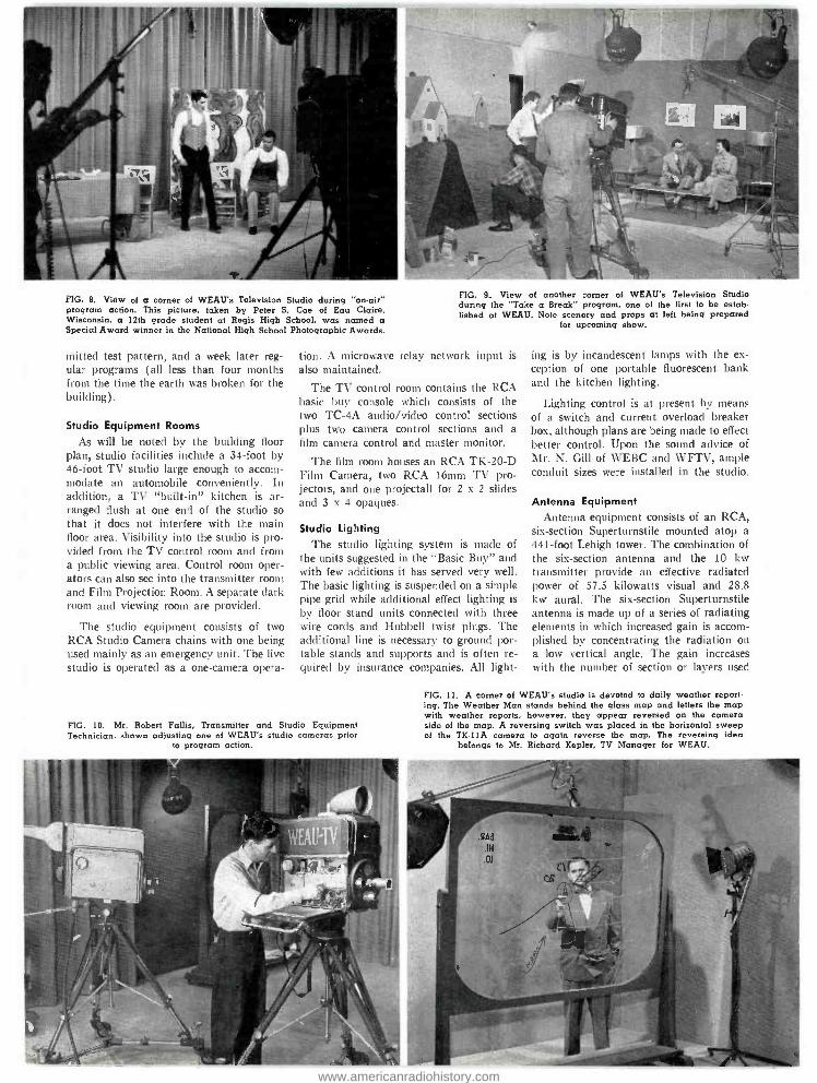
FIG. 8. View of a corner of WEAU's Television Studio during "on -air" program action. This picture, taken by Peter S. Coe of Eau Claire, Wisconsin, a 12th grade student at Regis High School, was named a Special Award winner in the National High School Photographic Awards.
milted test pattern, and a week later reg- ular programs (all less than four months from the time the earth was broken for the building).
Studio Equipment Rooms
As will be noted by the building floor plan, studio facilities include a 34 -foot by 46 -foot TV studio large enough to accom- modate an automobile conveniently. In addition, a TV "built -in" kitchen is ar- ranged flush at one end of the studio so that it does not interfere with the main floor area. Visibility into the studio is pro- vided from the TV control room and from a public viewing area. Control room oper- ators can also see into the transmitter room and Film Projection Room. A separate dark room and viewing room are provided.
The studio equipment consists of two RCA Studio Camera chains with one being used mainly as an emergency unit. The live studio is operated as a one -camera opera-
FIG. 9. View of another corner of WEAU's Television Studio during the "Take a Break" program, one of the first to be estab- lished at WEAU. Note scenery and props at left being prepared
for upcoming show.
tion. A microwave relay network input is also maintained.
The TV control room contains the RCA basic buy console which consists of the two TC -4A audio /video control sections plus two camera control sections and a film camera control and master monitor.
The film room houses an RCA TK -20 -D Film Camera, two RCA 16mm TV pro- jectors, and one projectall for 2 x 2 slides and 3 x 4 opaques.
Studio Lighting The studio lighting system is made of
the units suggested in the "Basic Buy" and with few additions it has served very well. The basic lighting is suspended on a simple pipe grid while additional effect lighting is
by floor stand units connected with three wire cords and Hubbell twist plugs. The additional line is necessary to ground por- table stands and supports and is often re- quired by insurance companies. All light-
FIG. 10. Mr. Robert Fallis, Transmitter and Studio Equipment Technician. shown adjusting one of WEAU's studio cameras prior
to program action.
ing is by incandescent lamps with the ex- ception of one portable fluorescent bank and the kitchen lighting.
Lighting control is at present by means of a switch and current overload breaker box, although plans are being made to effect better control. Upon the sound advice of Mr. K. Gill of WEBC and WFTV, ample conduit sizes were installed in the studio.
Antenna Equipment Antenna equipment consists of an RCA,
six- section Superturnstile mounted atop a 441 -foot Lehigh tower. The combination of the six -section antenna and the 10 kw transmitter provide an effective radiated power of 57.5 kilowatts visual and 28.8 kw aural. The six- section Superturnstile antenna is made up of a series of radiating elements in which increased gain is accom- plished by concentrating the radiation on a low vertical angle. The gain increases with the number of section or layers used
FIG. 11. A corner of WEAU's studio is devoted to daily weather report- ing. The Weather Man stands behind the glass map and letters the map with weather reports, however, they appear reversed on the camera side of the map. A reversing switch was placed in the horizontal sweep of the TK -11A camera to again reverse the map. The reversing idea
belongs to Mr. Richard Kepler. TV Manager for WEAU.
www.americanradiohistory.com
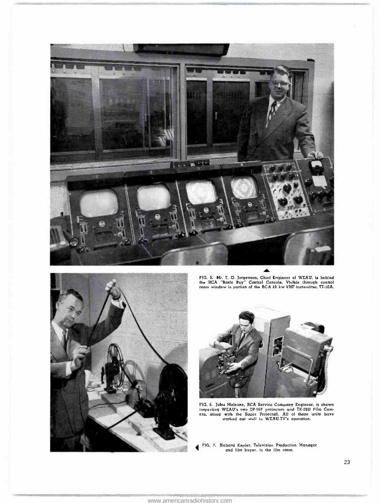
FIG. 5. Mr. T. O. Jorgenson, Chief Engineer of WEAU, is behind the RCA "Basic Buy" Control Console. Visible through control room window is portion of the RCA 10 kw VHF transmitter, TT -10A.
FIG. 6. Jules Maleone, RCA Service Company Engineer, is shown inspecting WEAU's two TP -16F projectors and TK -20D Film Cam- era. along with the Super Projectall. All of these units have
worked out well in WEAU -TV's operation.
' FIG. 7. Richard Kepler, Television Production Manager and film buyer, in the film room.
23
www.americanradiohistory.com

cuit to 4K6, causing it to close. Its contacts close the A -C to terminals 7 and 8 on the filament regulator, and to the filament volt- age control, which also puts A -C across the coil of 4K5. After 30 seconds 4K5 will close and its contacts close the A -C to the plate timer auxiliary, 4K20. 4K20 closes completing the A -C circuit to one side of the "Plate" switch.
If all interlocks are closed, the interlock indicator will be lit and the sequence of plate voltage relays can be started by closing the "Plate" switch. The following relays will operate. 4K4 closes applying A -C to the 400 volt and 575 volt modu- lator supplies. 4K22 closes completing the circuit to the coil of 4K21. 4K22 is closed by the current through 6R430, 6R428 and 6R429 which are connected across the 575 volt regulated supply for the modulator. 4K21 should now close completing the cir- cuit for the 4KI coil through the contacts of 4K20 which was closed preciously. 4K23 should close immediately following the closing of 4K4. It shorts the 20 ohm re- sistor in series with the primary A -C to the modulator supplies. 4K1 now closes applying three -phase 230 volt A -C to the primary of the final amplifier plate trans- former. When this occurs, 4K3 is actuated from across one leg of the A -C from the 4K1 contacts. 4K3 closes the A -C to the driver plate supply transformer. This com- pletes the sequence of relays, placing the transmitter on the air.
In the event of trouble, throwing on the plate switch will usually actuate one of the overload relays, which operate when a pre- set current through them is exceeded. They in turn open the coil circuit to the relay controlling the supply to the circuit in which the overload occurs. The overload relays are provided with flags which indi- cate which overload relay operated.
In some cases the actual overload may surge several other circuits and cause their flags to operate also, a condition which is inevitable since the actual overloaded cir- cuit may supply grid, screen, etc. voltage to several other circuits. However, the indi- cation is still of great value since by noting which flags came up it is possible to follow the sequence back by either blocking the last relay in the sequence, or in some cir- cuits, opening the switch to the last supply in the sequence inside the control bay. In this manner, the last relay in the sequence can be kept from closing and if all is well up to this point, no overload will occur. If not, the next relay in the sequence (com- ing back) can also be blocked and the switch closed again. In this manner the overloaded circuit can be definitely isolated.
b 694
-14
Tee, RESI TBB6 .-0-11-100--0--0-SES-.. REFLECT
O CONI RELAY
F+-n4
PLATE ON 613
6-233 4 1
l'b+ 4"U .-
4L .
751 C C000
- - -I
Pra i1-e
CCCO 1
PLATE
I
I
6-A4 6-16A 554 16A 4 19A i
II
41 I
r-- I
i
1
r---1 . i
P, DC MAC MAC IN°C MOD N9 .10 12 ]
I+121 y I
4N UNDER BIAS ~+ N°° rd"
i
I
Ì
1 I 1 1 1 I_J T T T T T T
NOTCHING , D , I1- 477 L -.1- --
PLATE - Y j »OTCN1»G1RE ON-FF ,-
15A 47F5 JPe! 52 Jell 4716
6+ e 1 L READY
6116_1u
-e0-0-0-0-0-0-0-0-071-0. 654 653 652 651
I 0 6-14AI O °« 14- 552 555 5S3 557 5X 55201 5-4C 450 459
I 455
0-Ó o-Ó O-ó O-Yb n-b--0--0--0 Ó GR» aUA
.11 ®TEL p4-4ew
63T4 ISZw
' f CCC
G9--O s4A
414 p
CONSOLE I RESET
...2A SIPÇ 472-6 ,e2.6 O
-4 ol sro
¿
1
¡
I
I
i 1
I I
I I
, NIe f ,b
Itt''__
1 4^4( .UZ-5 re23 b 6-,
RESET
3,.3 +V-] 6j.
,S) 0-55
DBYPA/PI-a CONSOLE
47 71.47- 46
4-434 4+4
A
445.4 r---- 20 1 PL TIMER AM
I
I
!
i
I
I
1
I I
L
L-'-----
4R6 4-34A 54,4 526A I Fl ON-OFF Ì -IJA 753
1
G Ca
FIL SN1 IF I 5-26A q 4V; 135.533
0
O 554 AW 1671N
L _
0 432 ,PN 0 lea .3 +xa
II
- ; 515 ON
5 Sw I +]A y i
i ; ;
YEL
I
1] GEN
eYEL CONSOLE I
1 ï-Ki - ! I
i--Kr 1 14JI-9 9 ,W-4 4J1-Nr I o--< ghu
4-3114 1 I 51 CI 14N2
-±-t---,TRANS ON-OFF 1
I -37A I- -II
F CT 52 1 Ì 1 i
'
----
655A
Yoo ooI I
+254
643A
634A 2.J UTO FIL
voLTCO»T 1121 81 APA»EL
1017
1 ey14N3
1
N2i1>
- +-
2J -
C»1ROL
11 21 191
---- 4T
I
51 I }-}---*-----7 -t}-+----}--642r
I I 1-+-t----
I 1
I 1
I
I
i
6vR1 11
J
o4A i ----,
j1'-4T0 PRI .LY1+OF 476
j
I
-- S22A .
SzJA
446A .-z9A
1010'.R5 R 1¡- c
1
.
I
I..
-T I
-2+ry
I
L .aa
1/ 4s C-4
42
I 4561NTMYRECT 4-5A 'I 4RIO 4<09
1 O L
RECTS
4-M
452E LINE
.T1
I
1 41-1 I
460
- 45
L V RECT
230 Y
30 T - 50-60+~ I
FIG. 2. Control circuit ladder diagram showing the arrangement of relays and contactors in the RCA TT -10AH. 10 kw VHF Transmitter.
The chart discussed here will by no
means replace the ladder diagram, but will
supplement it in a convenient form ,and
since it presents the operation of the relays
in order, permits isolation of the defective
circuit as discussed in the paragraph above.
The TT -10AH visual transmitter has been discussed here since it is the most complicated in its control circuitry. A sim- ilar chart can be easily compiled for the aural transmitter and 25 kw amplifiers if used. The same control circuit is used in the TT -1OAL, 10 kw transmitter.
19
www.americanradiohistory.com

WEAU... RADIO - TV The addition of television facilities to 11 EAU's AM and FM Broadcasting oper- ation required careful and extensive plan- ning. WEAU had been providing West Central Wisconsin with standard AM
Mr. W. C. Bridges, General Manager of the Arrowhead Network, started radio in 1913.
20
by T. O. JORGENSON Chief Engineer
Central Broadcasting Co.
Eau Claire, Wis.
Broadcast service for more than 17 years -and with FM since 1948. The arrival of TV to WEAU resulted from the careful planning and construction of plant facilities to house the studio, production activities, transmitter equipment, and AM studio and office operations, as well.
Building Planning
After much planning it was finally de- cided to locate the Radio -Television Build- ing at the edge of the City of Eau Claire, where it was possible to erect a 480 -foot self supporting tower, and also be within a block of bus service, water mains and reasonable telephone line charges. A scale model of the building was completed, using RCA Cutouts for planning the equipment layouts for the transmitter, studio, and con- trol rooms and using simple blocks for office layouts of desks and filing cabinets. Finally a building of 80 by 120 feet was
decided upon to house all the necessary operations of the proposed Radio and Tele- vision operation.
The general plans finally evolved and were approved by Mr. W. C. Bridges,
Mr. H. S. Hyett, General Manager of WEAU Radio and TV.
www.americanradiohistory.com
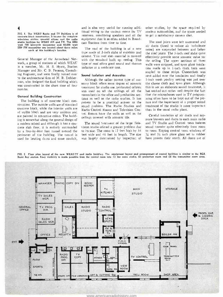
FIG. 1. The WEAU Radio and TV Building is of concrete block construction. It houses the complete television station, general offices and the radio studio facilities for WEAU AM and FM. The 5000 watt 790 kilocycle transmitter and 60,000 watt ERP FM transmitter are located about three miles
north of this building's location.
General Manager of the Arrowhead Net- work, a group of stations of which WEAU is a member, Mr. H. S. Hyett, Station Manager and Mr. C. B. Persons, Consult- ing Engineer, and were finally turned over to the architectural firm of M. R. Dobber- man, who designed the final building which was constructed in the short time of four months.
General Building Construction
The building is of concrete block con- struction. The outside walls are of standard concrete block, while the interior walls are of wylite block and are very uniform and are painted in attractive colors. The build- ing is somewhat along the general design of a modern school and although it has a con- crete slab floor, it is entirely surrounded by a four -by -four foot tunnel around the perimeter of the building. The tunnel is used for heating ducts and some conduit,
and is also very useful for running addi- tional wiring to the various rooms for TV receivers, monitoring speakers and all the equipment that is so often added in Broad- cast Stations from time to time.
The roof of the building is of a new type made of 3 -inch slabs of excelsior and cement. This roof slab material is covered with the standard built up roofing. This type of roof offers good sound and thermo isolation at a moderate cost.
Sound Isolation and Acoustics
Although the rather porous type of ma- sonry block offers some degree of acoustic treatment for studio use, perforated celotex was used on all the ceilings of all the rooms both in the office and production sec- tions as well as the radio studios. It has proven to be a practical answer to the sound problem. The Radio Studios and Radio Control Rooms and Television Con- trol Rooms have the walls as well as the ceilings covered with acoustic tile.
The sound treatment of the large Tele- vision studio offered a greater problem due to its size. The room is 17 feet high by 34 feet wide and 46 feet in length. The size was largely determined by inspection of
other studios, by the space required by modern automobiles, and the space needed to get a satisfactory camera shot.
The steel joists were left uncovered and air ducts (lined to reduce air turbulence noise) are suspended between and below the steel joists. The 3 -inch roof slabs quite effectively provide some acoustic value for the ceiling. The upper sections of three walls were stripped, and spun glass insula- tion made up in 1 -inch thick bats were stapled to these strips. Cheesecloth was next added over the insulation and finally 1 -inch mesh poultry netting was put over the cheese cloth and spun glass. Although this is not an elaborate sound treatment, it has worked out rather well despite the fact that the microphones used in TV program- ming often have to be kept out of the pic- ture and the importance of a proper sound treatment of the studio is more important than in the usual radio plant.
Careful insulation of air ducts and sep- arate blowers and ducts to each main radio and TV Studio and Control room isolates sound transfer quite effectively from room to room. Sloping control room windows of
and s ÿ inch plate glass set in rubber have proven their worth. All doors are of
FIG. 2. Floor plan layout of the new WEAU.TV and radio building. The equipment layout and arrangement of control facilities is similar to the RCA Basic Buy station. Easy visibility is made possible from the control room into (1) the main studio. (2) projection room and (3) the transmitter room area.
ENT.
GENERAL OFFICE
MANAGER ¡TRAFFIC
TV SALES MGR.
T V PROG. DIR.
RADIO SALES MGR.
COPY DIV. BOOK- KEEPER
TV
Irk OFFICE RECEPTN _J _
RADIO RADIO
STUDIO CONTROL
'NEWS SPOTS
FM & TAPE TV
AUDIO
PUBLIC VIEWING
CLO
FARM
SPORTS
NEWS
r
FAX.
RADIO PROD. DIR.
ENGRS OFF
TV COPY
FILM LIBRARIAN ART & CUTTING RM
MAIN
STUDIO
TV CONTROL
STORAGE
PROJ.
n TRANS.
TRANSMITTER ROOM
ROOM . SHOP AREA
PROPS. ENT. & LOADING
DOCK
www.americanradiohistory.com

FIG. 3. Ventilating and air conditioning system installed in ceiling of main studio. A large volume low velocity air system is used in order to reduce noise from air turbulance. The inside areas of all ducts are lined with a 1.inch blanket of spun glass insulation which has aided in reducing blower noise.
the sound proof type and a sound lock system is used in the radio section of the building.
Heating and Ventilation The building is heated by an oil -fired,
low- pressure furnace which supplies heat to the building by coils in the ventilating system and by perimeter heating. The sys- tem is controlled by six thermostats in the various sections of the building.
The entire building is ventilated by fil- tered air. (All air being drawn in through air filters.) Additional cooling of the air is accomplished by water coils located in the blower units. As an aid in further cool- ing of the building, some of the exhaust water (obtained from the city water sys- tem) is sprinkled on the roof.
A manifold was placed over the tops of all the equipment racks and a small blower was installed to exhaust the warm air from the film and studio camera power supplies and other rack mounted equipment.
FIG. 4. Mr. Robert Faults, Transmitter Technician and Operator, pictured here, together with all of the members of the WEAU transmitting crew aided in installing the studio and transmitter equipment. The years of experience gained in operating a 5 kw, 790 kc and a 10 kw, 94.1 me transmitter enabled the regular transmitter crew
to work into the TV operation quite well.
22
The main transmitter room is equipped with a large blower which is installed over the top of the transmitter. Depending on the air and temperature, air is either re- circulated within the room or exhausted. No attempt was made to duct the trans- mitter directly as past experience had proved this to be unwise.
General Equipment Layout
The (VEAU -TV and Radio Building is
an example of small city Radio and Tele- vision operation. The television section consists mainly of the Famous "RCA Basic Buy" with two cameras and building de- sign and equipment layouts were aided by the many fine examples in past issues of BROADCAST NEWS.
The building consists of the complete office section serving both Radio and TV, the Complete Television operation, includ- ing production, studios, control room and transmitter and the Radio production and program section including control room. The Radio Transmitters, comprising a 5,000 watt 790 kilocycle AM transmitter feeding a three -tower, directional system and a 10 -kw FM transmitter with an ERP of 60 kw on 94.1 me are located three miles north of the "TV Radio Center Build- ing". Since the building is located at the edge of Eau Claire, a line -switch center is mounted at the Eau Claire Hotel and sev- eral lines connect it to the Radio Control Room.
Installation of Equipment All the studio equipment was set up at
the WEAU Radio Transmitter and tested and adjusted before the TV Building was ready for occupancy. The trans- mitter and studio /video and audio equip- ments were installed by the technical crew of WEAU and tested out and adjusted by the RCA Service Co. Although the normal number of installation and testing prob- lems were encountered, the station trans-
www.americanradiohistory.com

in the antenna. Each section consists of four radiators, mounted at 90 degree intervals around the pole. Teflon line was used with the new six-bay antenna. Low line loss and excellent standing wave ratio was obtained. The vertical run was suspended with spring hangers and the horizontal run was supported by a simple roller arrange- ment and covered with sheet iron to deflect falling ice from the tower.
The sideband filter was erected overhead by extending the legs with 172-inch pipe as suggested by Mr. Jules Maleone of the RCA Service Co. The mounting provided easy access to all parts of the filter.
Transmitter Room and Equipment The RCA TT -10AH transmitter is located in a room
with shop facilities located at one end. Entry to the transmitter room is gained from the TV control room, Projecttion room and the studio storage area.
The TT -10AH transmitter, except for two external plate power transformers, is housed in six identical cubicles requiring a floor area of only 43.3 square feet. Sliding panel type doors give complete access to com- ponents and tubes from both front and rear of each cabinet. Cabinets are mounted adjacent to each other on rails which serve as a common base frame and wire trench. Built -in wiring ducts and preformed cable harness elim- inated many of the ordinary time consuming details during installation. Tuning controls are brought out to panel positions, and metering is provided for servicing and routine tests.
FIG. 12. Hugh Mulhollam, Transmitter Technician, is shown tuning the Visual Exciter Section of the TT -10AH, RCA 10 kw
VHF Transmitter.
FIG. 13. The 6 -bay RCA Superturnstile antenna hall way up. The antenna was placed on top of a 441 -foot Lehigh tower making the
overall height of 480 feet.
FG. 14. Marshall Williamson, Transmitter Technician and Operator, shown adjusting the Channel 13 sideband filter. The entire unit was mounted on four legs next to the transmitter. This method of mounting has proved to be very practical since it allowed easy access to all
parts and short coax line runs.
25
www.americanradiohistory.com

uS;
COLOR STRIPE ADDED TO STATIONS
MONOCHROME SIGNAL
TV stations going into color can speed up the installation and adjustment of color receivers in their area by making use of the RCA Type WA -8A Color Stripe Gen- erator (Fig. 1). It enables any TV sta- tion (which is equipped to transmit net- work color) to add a narrow color stripe to its regular black and white television sig- nal. This stripe is practically unnoticeable on ordinary black and white receivers. However, on color receivers it produces a thin vertical stripe of greenish -yellow color at the right hand edge of the picture (Fig. 2). By simply observing the presence, or absence, of this color stripe the serviceman can tell whether or not the color receiver he has just installed will receive the sta- tion's color pictures -even though the sta- tion at that moment is telecasting only black and white pictures.
Why It Is So Important At the present time color television pro-
grams are aired only a few hours a week on most stations. Although the proportion of such programs is expected to increase
FIG. 1. Front view of the new RCA Type WA -8A Color Stripe Generator, new testing device to aid servicemen during home color receiver installation. The generator adds color bursts to regular black and white television signal and enables technicians to determine whether local station's color signals are capable of being picked -up on newly -installed
receivers in area.
26
by E. E. GLOYSTEIN Engineering Products Division
rapidly it will be some time before color programs are available during most day- time hours. This makes it difficult for the serviceman because it means that in most cases he will not be able to make an im- mediate "off- the -air" check of the opera- tion of the color receivers he installs.
Actually, two problems confront the serviceman who is installing color receiv- ers. The first problem is encountered in setting up the receiver in the home and making sure that it is adjusted for proper operation on both color and monochrome. During the early stages of color program- ming only a few color programs will be transmitted by most stations. Because the serviceman cannot afford to wait around for one of these programs he must have some means of checking the receiver ad- justment for color even though no color program is on the air at the time. To solve this problem RCA has developed, and is
making available through the RCA Tube Division, a new portable Type WR -61A simplified dot and color bar generators-
that enable a service technician to fully adjust a color receiver in the home even though no television program (either mono- chrome or color) is on the air at the time.
The use of this portable color test equipment solves the serviceman's first problem. However, he is faced with an- other problem, which is how to determine whether the receiver, even though correctly adjusted for color, will receive a satisfac- tory color picture at a particular location. Other factors, such as antenna response, transmission line loss, overall systems ade- quacy or propagation path may cause reception difficulties with even the best engineered and most carefully adjusted receivers.
Experience has indicated that under cer- tain conditions of multipath reception or improper orientation of the receiving an- tenna it is quite possible to pick up a satis- factory monochrome picture but to have the color subcarrier almost completely can- celled. Thus it is not possible to determine for sure that a particular color receiver
c
www.americanradiohistory.com
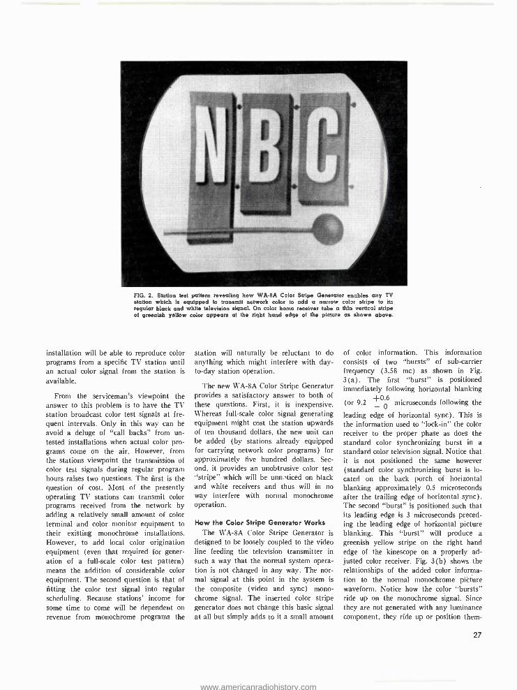
FIG. 2. Station test pattern revealing how WA -8A C_lor Stripe Generator enables any TV station which is equipped to transmit network color to add a narrow color stripe to its regular black and white television signal. On color home receiver tube a thin vertical stripe of greenish yellow color appears at the right band edge of the picture as shown above.
installation will be able to reproduce color programs from a specific TV station until an actual color signal from the station is
available.
From the serviceman's viewpoint the answer to this problem is to have the TV station broadcast color test signals at fre- quent intervals. Only in this way can he
avoid a deluge of "call backs" from un- tested installations when actual color pro- grams come on the air. However, from the stations viewpoint the transmission of color test signals during regular program hours raises two questions. The first is the question of cost. Most of the presently operating TV stations can transmit color programs received from the network by adding a relatively small amount of color terminal and color monitor equipment to their existing monochrome installations. However, to add local color origination equipment (even that required for gener-
ation of a full -scale color test pattern) means the addition of considerable color equipment. The second question is that of fitting the color test signal into regular scheduling. Because stations' income for some time to come will be dependent on
revenue from monochrome programs the
station will naturally be reluctant to do anything which might interfere with day - to -day station operation.
The new WA -8A Color Stripe Generator provides a satisfactory answer to both of these questions. First, it is inexpensive. Whereas full -scale color signal generating equipment might cost the station upwards of ten thousand dollars, the new unit can be added (by stations already equipped for carrying network color programs) for approximately five hundred dollars. Sec-
ond, it provides an unobtrusive color test "stripe" which will be unn,"ticed on black and white receivers and thus will in no way interfere with normal monochrome operation.
How the Color Stripe Generator Works The WA -SA Color Stripe Generator is
designed to be loosely coupled to the video line feeding the television transmitter in such a way that the normal system opera- tion is not changed in any way. The nor- mal signal at this point in the system is
the composite (video and sync) mono- chrome signal. The inserted color stripe generator does not change this basic signal at all but simply adds to it a small amount
of color information. This information consists of two '`bursts" of sub -carrier frequency (3.58 mc) as shown in Fig. 3(a). The first "burst" is positioned immediately following horizontal blanking
(or 9.2 +OQ microseconds following the
leading edge of horizontal sync). This is
the information used to "lock -in" the color receiver to the proper phase as does the standard color synchronizing burst in a
standard color television signal. Notice that it is not positioned the same however (standard color synchronizing burst is lo- cated on the back porch of horizontal blanking approximately 0.5 microseconds after the trailing edge of horizontal sync). The second "burst" is positioned such that its leading edge is 3 microseconds preced- ing the leading edge of horizontal picture blanking. This "burst" will produce a
greenish yellow stripe on the right hand edge of the kinescope on a properly ad- justed color receiver. Fig. 3(b) shows the relationships of the added color informa- tion to the normal monochrome picture waveform. Notice how the color "bursts" ride up on the monochrome signal. Since they are not generated with any luminance component, they ride up or position them-
27
www.americanradiohistory.com

selves on the average of the luminance value present in the monochrome signal at that particular time.
The first "burst" was positioned in the picture information just following horizon- tal blanking for a definite purpose. With this configuration the color producing cir- cuits in a color receiver will not be actu- ated. In other words, a viewer can continue to watch a monochrome program on a color receiver, even though the color stripe gen- erator is being used, and see only a mono- chrome picture. Thus he will not be an- noyed by a greenish -yellow bar or stripe along the right hand side of the kinescope. However, when a serviceman wishes to check out a receiver installation he needs only to make a minor adjustment in the horizontal oscillator of the receiver in order to make the stripe visible. (Details of this adjustment are discussed below.) The beauty of this particular arrangement is
that color receivers will be immune to this new color signal unless they are purposely misadjusted by trained technicians. The ordinary viewer will not be annoyed by the extra color stripe and by the color noise when viewing a monochrome program. When a color program is being broadcast, the local broadcasting station will have al- ready disabled the color stripe generator signal so as not to cause color interference. On a monochrome receiver the addition of the color stripe signal will have little or no effect because the subcarrier (3.6 mc) is frequency interlaced and essentially can- cels out because of the persistence of vision
of the eye. In addition, most monochrome receivers have relatively low response at 3.6 mc making the stripe even less visible.
To gain maximum benefit from use of
the color stripe generator, there should be
agreement between the broadcast station and the local service people as to time and method of operation. An automatic timer (not supplied as part of the equipment) may be installed to insert the color stripe for a given period of time at regular inter- vals. Use of any such timing cycle should be brought to the attention of all area TV agencies in order to speed color receiver installations and adjustments.
Description of the WA -8A Generator
The circuitry of the WA -8A Stripe Gen- erator is indicated in the block diagram (Fig. 4). The first block indicates the sync separator and pulse discriminator. Its pur- pose is to "strip" the sync from the com-
28
(B) HORIZONTAL SYNC
(A)
0. 4 P
MONOCHROME VIDEO
3 MICROSECONDS
_L_ 921246' MICROSECONDS
0.4v P P B.CYCLES MINIMUM AT 3.579545 MC
FIG. 3. Diagram of signal produced by the Color Burst Generator. Line (a) represents color bursts of sub.carrier frequency. and line (b) is composite signal from stripe generator.
posite monochrome signal. An additional function has been added, however. No bursts or stripes should appear for 9 lines during the vertical blanking interval, so a "burst eliminate" circuit has been added to prevent the separation of pulses during the vertical sync and equalizing pulse in- tervals. The output of this stage, there- fore, is a series of pulses at horizontal rate with a 9 -line gap during the vertical inter- val. This information is differentiated and applied to the burst position multivibrator which in turn drives the burst width multi - vibrator. Its output is the positive pulse necessary to trigger the burst gating am- plifier. A second output drives the stripe position multivibrator which in turn drives the stripe width multivibrator. Its output is also a positive pulse necessary to trigger the stripe gating amplifier. The subcarrier signal at 3.579545 mc, necessary for the gating amplifiers, is produced by a stable oven -controlled crystal oscillator. Its out- put is supplied to the gating amplifiers. The outputs of the gating amplifiers are fed to the mixer and output stage. Its output is in turn fed back to the video line. Notice that the video line is never broken. If failure of the stripe generator should occur the monochrome signal would not be affected. Coupling of the output signal to the video line is so loose that the
monochrome signal is essentially unaffected but the color bursts or envelopes are added or superimposed on it.
The WA -8A color stripe generator is
built on an 8g inch high bathtub chassis designed for standard rack mounting. It employs 11 tubes, 2 of which are used in the self -contained power supply. Fig. 1
shows a front view of the generator. The only unusual component involved is the thermostatically controlled oven for the oscillator crystal. Two video jacks are pro- vided on the rear of the chassis for video input and output. The only power connec- tion required is to a standard 117 volt, 60 cycle a -c line through a six -pin Jones plug. Two pins of this same plug are used for connection to a remote switch for adding or removing the color bursts from the monochrome signal at some location re- mote to the actual stripe generator. The unit weighs approximately 20 pounds and is finished in standard umber gray com- parable to other RCA equipments.
All controls for the generator are ac- cessible from the front. Front panel con- trols consist of the Remote - Off -Local switch which applies +B to the subcarrier oscillator and mixer output tubes in the remote and local positions and removes it from the tubes in the off position; pulse
www.americanradiohistory.com

discriminator bias pot for adjusting the clipping level so that under all values of picture information nine lines or bursts are eliminated during the vertical blanking interval; subcarrier frequency control -a trimmer to adjust the oscillating frequency of the oven controlled crystal to exactly 3.579545 megacycles; subcarrier output control -a level setting control common to both burst and stripe for adjusting their amplitudes with respect to the monochrome signal; three separate controls associated with the color burst for adjusting its width, its amplitude and its position with respect to sync; envelope shaper control- essen- tially a control to adjust a bandpass filter (a low Q resonant circuit) for best shape of the burst and stripe envelopes; oscillator plate tuning -an inductance control for adjustment of the crystal oscillator plate circuit for maximum frequency stability; and an on -off power switch removing the a -c power input to all of the unit except the heaters used in the crystal oven. In addition to the above controls, there are three panel lights. One is used to indicate power on or off ; one is paralleled with the crystal oven heaters to indicate off -on cycling of this unit; the third panel light
illuminates when +B is applied to all parts of the generator (when the Remote - Off -Local switch is in the local or remote position) .
The WA -8A Color Stripe Generator is
supplied with all tubes in place. It can be installed in a standard 19 -inch rack with- out further preparation. A position in the rack can be selected that will permit con- venient operation of the controls and pro- vide access to the rear of the chassis for servicing. It can be housed conveniently with the stabilizing amplifier in the trans- mitter location, or in the studio with other terminal equipment somewhere near the output line to the transmitter.
How the Color Stripe Is Used to Adjust a Receiver
To use the color stripe generator signal in checking a color receiver the horizontal circuits must be misadjusted to the point that the burst gate will accept the "burst" following horizontal blanking. The RCA Service Company engineers suggest this be done on RCA color receivers by connect- ing a 0.005 microfarad capacitor from the sync amplifier tube to ground (pin 6 of
V118A to ground on CT -100 receiver). An alternate method that will work on most receivers in strong signal areas con- sists of detuning the horizontal oscillator transformer (top slug) to move the picture to the left. Receivers of other manufac- turers may need different adjustments. In field tests all the horizontal locking cir- cuits presently being used in color receiv- ers were checked with satisfactory results.
The check to see if a receiver location will properly accept a color signal consists of observing the presence of a greenish - yellow stripe on the right side of the kine- scope picture, after the horizontal circuits have been properly misadjusted. If no stripe, or a stripe of the wrong color, is observed, a check on the receiver perform- ance should be made. If the receiver oper- ation is normal, the antenna or antenna system should be checked for mismatch, improper position or orientation. The trans- mission line should be checked for condi- tion and location. If the color stripe signal is being broadcast and the local conditions are all in order, the color stripe should appear on the receiver in its characteristic greenish -yellow hue.
SIGNAL IN
SYNC SEP.
SIGNAL OUT
73 OHM VIDEO CABLE
BURST
ELIMINATE
DIFFER- ENTIATING
CRT.
BURST POSITION
M. V.
DIFF.
CNT
BURST WIDTH M. V.
DIFF.
CNT
STRIPE POMITION
DIFF. CRT
OVEN CONTROLLED
CRYSTAL OSCILLATOR
BURST GATING
AMP
STRIPE WIDTH GÁMIIPG
BUFFER AMP
BAND PASS FILTER
BAND PASS FILTER
FIG. 4. Simplified block diagram of Color Stripe Generator WA.8A.
29
www.americanradiohistory.com

WTVR COMPLETES GIANT RCA 6 Bay Superturnstile and
by JAMES W. KYLE Chief Engineer
In early 1954, WTVR, "The South's First Television Station ", completed construction of its giant self -supporting television an- tenna and installation of its new RCA 25 kilowatt transmitter, transferring transmis- sion to its new location, Tilden and Cut - shaw Avenue, just to the rear of its studio building, in the geographical center of the city of Richmond. Actually, this culminated a long period of planning from the early pioneering days of 1944, when the sta- tion first made application for construction permit.
Heretofore the station's transmitting fa- cilities have been located on Staples Mill Road, just off West Broad Street, where modern transmitting facilities and a 642 - foot tower are now serving as a complete auxiliary plant. The move to the new loca- tion was prompted by two factors. First, a giant maximum height, 1049 -foot antenna could not be installed at the old location,
Aerial view of WTVR self supporting tower, 1049 feet, lo- catad in the geographical center of the City of Richmond.
o Wilbur M. Havens (center), Owner -Manager of WTVR, receives lamp from W. T. Angle, tower erector, for placing in antenna beacon, just prior to the RCA Superturnstilé s journey through space to the top of the tower pictured left. Mr. G. W. Gilmer, electrical contractor, looks on. The beacon carried four flags, two American, a Confederate, and the skull and crossbones representing the erectors who said they always attach the skull
and bones to bring them good luck.
30
www.americanradiohistory.com

TOWER- MAXIMUM POWER 25 kw Transmitter Installation
Newly erected transmitter building at the base of the tower. The tower legs are obscured from view by 30 -toot cedars and 25 -foot holly trees, so placed as to beautify the area since the location is in one of Richmond's finest residential areas.
for to do so would cause interference to the station's existing AM array. Secondly, the new location in the geographical center of the City of Richmond offered additional coverage advantages, and since the tower gives the effect of virtually straddling our main business thoroughfare, Broad Street. the publicity value was a definite consideration.
Since the tower was to be erected in the midst of Richmond's finest residential sec- tion, it was first decided to take every safety measure at our disposal in its erec- tion, which extended over a fourteen month period. Although tests indicated the ground to be of sufficient quality to erect the giant tower without pilings, it was decided that they be used as an extra safety measure. Twenty concrete pilings per pier, thirty feet in length, reinforced with three -quarter inch deformed steel bars were first driven to refusal. Sixteen by Sixteen foot mats,
each three feet thick, were mounted on the pilings, and finally pyramids under each leg of the tower tapering from a square twelve feet at the bottom to three feet at the top completed the foundation. The total weight of the concrete and reinforcing members in the foundation alone approxi- mates one and one -half million pounds.
The four -legged tower, fabricated by the Lehigh Structural Steel Company, spans seventy -five feet at its base with a gradual taper to a six foot square at its top. The width of the base of the tower prevented the use of an ordinary gin pole, and it is
unique that Wilbur M. Havens, Owner - Manager of WTVR, designed a ninety -six foot aluminum gin pole which was used throughout the construction period. The pulley at the head of the gin pole was so machined as to describe a 360 degree circle. Another advantage of the pole was the fact that it was constructed in sections, making
it possible to be shortened as work pro- gressed to more narrow portions of the tower. This one feature was responsible for expediting the construction immeasurably.
RCA, TF -6BM Six -Section Superturnstile When the tower was completed, it was
decided to partially dismantle the TF -6BM superturnstile antenna and install it in three sections, and again this decision was prompted by the fact that we were work- ing in the heart of a residential area. There could be no mistakes. As a result, the an- tenna was first completely assembled on the ground and tested. Secondly, it was dis- mantled making sure that all feed lines were carefully marked and numbered so that the riggers could re- assemble it prop- erly in the air. As a result, the VSWR was the same in the air after re- assembling as the ground test indicated. The tower was completely erected without a single major or minor mishap.
31
www.americanradiohistory.com
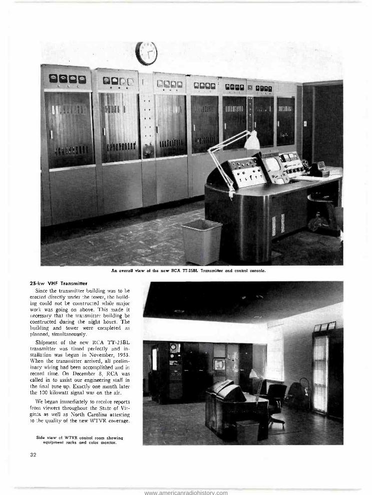
U
An overall view of the new RCA TT.25BL Transmitter and control console.
25 -kw VHF Transmitter
Since the transmitter building was to be erected directly under the tower, the build- ing could not be constructed while major work was going on above. This made it necessary that the transmitter building be constructed during the night hours. The building and tower were completed as planned, simultaneously.
Shipment of the new RCA TT -25BL transmitter was timed perfectly and in- stallation was begun in November, 1953. When the transmitter arrived, all prelim- inary wiring had been accomplished and in record time. On December 8, RCA was called in to assist our engineering staff in the final tune -up. Exactly one month later the 100 kilowatt signal was on the air.
We began immediately to receive reports from viewers throughout the State of Vir- ginia as well as North Carolina attesting to the quality of the new WTVR coverage.
Side view of WTVR control room showing equipment racks and color monitor.
32
www.americanradiohistory.com

Results have surpassed our fondest expec- tations. Total potential television homes. by the mere throwing of the switch to our new installation, increased 423%.
Color equipment for relaying network color programs has recently been received from RCA, and before this article is
printed, it is anticipated the station will be bringing Virginia and North Carolina the first in color television.
The new WTVR stands as a landmark throughout the State of Virginia; the ultra modern transmitter building, thirty -two by sixty feet, finished in buff brick, beautifully shrubbed in keeping with the residential area where it is located, stands as a model. The interior of the building is elaboratele panelled and houses spacious storage facil- ities as well as a modern machine shop and repair facilities. It is unique that the only wood used in the building was for the front door. Again this was a fire precau- tion due to the location of the building immediately under the tower.
Our primary emphasis throughout the construction was placed on building the finest Maximum Power, Maximum Height installation money could buy -RCA all the way- without sacrificing beauty. This is
the new WTVR, "The South's First Tele- vision Station."
Visual final amplifier showing sideband filter. 111©®©WOR®®1.
Picture at left) is view of WTVR 642 -foot auxiliary tower and RCA Superturnstile Antenna. The WTVR auxiliary transmitter building below houses complete auxiliary audio and video facilities. These facilities can be placed into operation instantly upon a failure at the main transmitter location. Signal is micro -waved from studio to auxiliary transmitter by RCA Link.
33
www.americanradiohistory.com
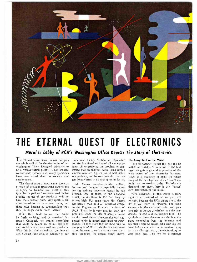
THE ETERNAL QUEST OF ELECTRONICS Mural In Lobby of RCA's Washington Office Depicts The Story of Electronics
The 24 -foot mural shown above occupies one whole wall of the elevator lobby of our Washington Office. Designed primarily to be a "conversation piece ", it has aroused considerable interest and many questions have been asked about its concept and development.
The idea of using a mural came about as a result of previous frustrating experiences in trying to decorate wall areas of this type. In the past we have often used photo- graphic murals of our products, only to have them become dated very quickly. On other occasions we have used maps, but these have become so commonplace that they no longer excite much interest.
What, then, could we use that would be fresh, exciting, and of sustained in- terest? Obviously we wanted something that would be symbolical of our company and would have a tie -in with our products. With this in mind we enlisted the help of Mr. Stewart Pike who, as manager of our
34
Functional Design Section, is responsible for the functional styling of all our equip- ment. After studying the problem he sug- gested that an abstract mural using simple conventionalized figures would best solve our problem, and he recommended that we get John Vassos to do such a mural for us.
Mr. Vassos, versatile painter, author, lecturer and designer, is especially known for the striking large -size murals he has created. One of these, in the Condado Hotel, Puerto Rico, is 120 feet long by 9 feet high. For some years Mr. Vassos has been a consultant on industrial design to the Engineering Products Division of RCA. Thus, he is very familiar with our products. When the idea of doing a mural on the broad theme of electronics was sug- gested to him it immediately fired his imag- ination. In fact, from then on there was no stopping him! With only the briefest orien- tation he went to work and in a very short time produced the design shown +above.
The Story Told in the Mural Like all abstract murals this one can be
looked at broadly, or in detail. In the first case one gets a general impression of the wide sweep of the electronics business. When it is examined in detail the whole story of the development of electronics un- folds in chronological order. To help un- derstand this story, here is Mr. Vassos' own description of the mural.
"The movement in this mural is from right to left instead of the accepted left to right, because the RCA offices are to the left as you leave the elevator. The basic elements in the electronic field, and par- ticularly in the art of wireless, are the con- denser, the coil, and the vacuum tube. The symbols of these elements are the first de- signs emanating from the inventor and scientist (extreme right), who with his left hand holds a coil while in his creative right, as in an all -magic way, the electronic sym- bols take form. The two red directional
www.americanradiohistory.com

lines lead to a group symbolizing broad- casting, the application of radio which has had such a powerful influence on our lives. The symbol of ether and space, which ap- pears three times in the mural, also links this grouping.
"The two figures next left represent Mr. and Mrs. America. From them springs the giant turnstile TV antenna, indicating the advent of one of the wonders of this age. As we move on to the left, the fascination of color TV, indicated by a stylized camera in operation and the mixing of the three basic colors -red, green and blue, rightly dominates the center of the mural.
"Next comes the protective theme of electronics. Just above the color camera, against a green background signifying 'Terra', stands the symbolic army with a projectile going into space. The air force, to the left, is a winged man going into space with two yellow wings. Our shores and sea (a deep blue) are in the pattern, and the hills are in the distance. The navy is expressed by a white figure pointing with radar and the marine is symbolized with a walkie- talkie, completing the four branches of the service.
"Concluding the conception is a look into the future; it is fitting and expresses the objectives of a great company. The atomic era is here and, appropriately, an- other symbolic scientist, in contrast to the one who used electrons, now controls the atom. As we look into the distance in the upper lefthand horizon, we see man facing new vistas of the atomic age, which will make this world a better place in which to live."
How It Was Applied to the Wall Many visitors have asked how such a
large mural -24' x 8' -was painted on the wall. Actually, the art of producing large murals has not changed much from the time of ancient Greece and the Renais- sance. The artist begins by making a small -sized sketch. Most of the creative work is done at this point. When the sketch is completed the next step is to make a cartouche. A cartouche is a drawing on a paper identical in size with the wall itself and on which the sketch is blown up in outline. In the old days they would square it off from the sketch, let's say an inch to a foot. Today there is an easier and more scientific approach. A baloptican (magic
lantern) is used to project the design di- rectly on the cartouche in the darkened studio. The artist can then trace his own outline and make any changes and im- provements he wishes right on the spot. This large line drawing is next perforated (along the sketched lines) with a sim- ple device like a tooth -edged wheel. The paper is then taken to the location and with masking tape fastened on the wall, which has been thoroughly prepared with size and two coats of the background color. With fine powder, the drawing is "pounced ". The powder goes through the perforations, thus transferring the outline to the wall. Next the artist, or his assist- ants, fill in the colors, using the original small -sized sketch as a guide. The result is an exact large -scale reproduction of the artist's original concept.
The use of strong solid colors gives the mural a startling impact. When visitors step off the elevator and view the mural for the first time the effect is electrifying. Invariably they stop to look at it, and almost always they have something to say about it. We wanted a "conversation piece ", and there is no question but that John Vassos has created exactly that.
35
www.americanradiohistory.com
Varnum and Hill Named to Managerial Broadcast Sales
Posts in Home Office at Camden
W. B. Vcrnum
VARNUM, NEW MANAGER OF BROADCAST EQUIPMENT SALES
Walter B. Varnum has been appointed to the post of manager, broadcast equip- ment sales, Engineering Products Division, Radio Corporation of America. In this position he will handle home office sales activities under the supervision of E. C. Tracy, general sales manager.
Mr. Varnum will coordinate the sale of UHF and VHF Transmitter and Antenna Equipment, Monochrome and Color Video Equipment, and AM Transmitting and Audio Equipment. His activities will em- brace liaison work with Merchandising and Product Plannnig sections.
An RCA broadcast equipment sales rep- resentative in the Kansas City region for the past five years, Mr. Varnum now makes his headquarters in the Division's Camden home office.
Prior to his sales assignment in Kansas City, he was for five years an RCA tele- vision transmitter design engineer. and has been associated with stations WREN, To- peka; WLS, Chicago; KSTP, St. Paul, and WJIM, Lansing. He is an engineering graduate of the University of Kansas.
HILL APPOINTED MANAGER OF NORTHERN BROADCAST FIELD SALES
Also named to a newly created home - office position is J. Edgar Hill, who has been appointed manager of Northern
36
broadcast field sales. In this position he will supervise the activity of broadcast field sales personnel in the Boston, New York, Chicago, Cleveland, and Kansas City regions.
Mr. Hill has been an RCA broadcast equipment sales representative in the Bos- ton region since 1947. Prior to this sales assignment, he had been with the broad- cast sales section in Camden and with the RCA aviation equipment engineering sec- tion where he contributed to the design of airborne radar equipment. Mr. Hill at- tended the Drexel Institute of Technology.
I. E. Hill
Almen and Ulasewicz in Field Sales ULASEWICZ TO BOSTON
Joseph P. Ulasewicz has been named to the post recently vacated by J. E. Hill, that of broadcast equipment sales repre- sentative for the Boston Region.
Ulasewicz joined RCA in audio and video engineering. Prior to his field assign- ment, he served in the broadcast equip- ment home office sales group.
He holds both Bachelor's and Master's degrees from Rensselaer Polytechnic In- stitute.
I. Almen
ALMEN TO KANSAS CITY
Replacing W. B. Varnum in the Kansas City office is John Almen who has taken the position of RCA broadcast equipment sales representative for that region.
Almen has worked in broadcast engi- neering and in the home -office sales mer- chandise section. He was principally con- cerned with the color equipment program.
He is a native of Minneapolis, Minne- sota and holds a degree in electrical engi- neering from the University of Minnesota. J. P. Ulasewicz
www.americanradiohistory.com

C. A. Wallack Is Named Denver Representative
WALLACK TO DENVER
Chester A. (Chet) Wallack has joined the Broadcast Marketing Department as field sales representative for the Denver Region.
Mr. Wallack is former chief engineer of station KVGB in Great Bend, Kansas where he served since 1948. He was the chief engineer at the time of construction of KTOP and KTSJ -FM in Topeka; was
F. A. Timberlake
TIMBERLAKE TO CHICAGO
Floyd A. (Tim) Timberlake has joined the RCA Broadcast Marketing Depart- ment as field sales representative in the Central Region with headquarters in Chicago.
Mr. Timberlake served as television op- erations supervisor of the Central Division of the American Broadcasting Company in Chicago before joining RCA. He began broadcast work at station WCAZ, Carthage in 1936. He has also been on the engineer-
C. A. Wallack
a field engineer for the Air Force during the war; and later was an instructor in
an advanced electronic school of the Navy. Before the war he was with station WIBW in Topeka.
F. A. Timberlake
Takes Field Post
in Chicago . . .
ing staffs of stations W1i'AE (now WJOB) in Hammond, Ind.; WIND at Gary, and WHFC and WEHS in Chicago.
During the war he was a project engi- neer at the Signal Corps' Evans Signa] laboratory in Belmar, N. J. In 1948 he joined ABC in Chicago in television operations.
He is a senior member of the IRE and well known as an amateur radio operator. using the call W9RZP for more than twenty years.
RCA Makes
Old Cameras Like New Again
IFYour Camera is more than three years old
Your picture quality is slipping You are interested in putting the best possible picture on the air
THENYou will want to take advan- tage of RCA's new overhaul and modi- fication program ... a one -stop service engineered for your camera and de- signed to provide maximum flexibility in television camera operation.
RCA., Camera Overhaul and Modification program is designed to bring your cameras up to date with the latest developments in camera construction and design. This modification service, exclu- sive in the television industry, is performed under the direct supervision of men who have pioneered in Television Broad- casting.
YOUR camera reflects the qual- ity of your station. You cannot afford to risk poor picture qual- ity against the potential of your market and keep your organiza- tion operating at a profit. You owe it to your technicians, and above all, to yourself.
For more information, write for our free folder 24 STEPS TO BETTER CAMERA PERFORMANCE, or con- tact your nearest Broadcast Repre- ,entative.
Return Apparatus Control Building 8-2
WOodlawn 3 -8000, Ext. PC -2834
RCA Service Company, Inc. A Radio Corporation of America Subsidiary
Camden 2, New Jersey
37
www.americanradiohistory.com

FIG. 1. Temporary Studio "C" at KGO -TV, San Francisco with temporary lighting grid installed.
INSTALLING A RE- USABLE TV LIGHTING GRID AT KGO -TV
With an ever increasing number of small television stations taking to the air, TV studios will be springing up not only in specially designed buildings, but in for- gotten mansions, in radio studios, garages. skating rinks and in old stables. Meeting and solving the problem of temporary stu- dio installations will become an everyday procedure to construction engineers from coast to coast. Space alone does not make a TV studio. The necessity of lighting sets and performers demands that some atten- tion be given to a method of suspending light units. Even as a minimum considera- tion, a stationary, permanent pipe grid is of incalculable value in every day opera- tion. A variety of interesting and unique studios will result as local conditions are encountered. Perhaps some aid to future planners of temporary TV studios can be obtained from an analysis of KGO -TV's Studio "C" in San Francisco. The unique use of Unistrut metal framing made pos-
38
by EDWARD B. SMITH Production Director, KGO -TV
sible an economical, portable and com- pletely satisfactory light grid installation.
In May, 1952, as part of a planned ex- pansion program, KGO -TV, The American Broadcasting Company station in San Francisco. obtained additional studio space in San Francisco's Radio City building. Studio "C ", 46 feet long, 23 feet wide, and 17 feet high was obtained. This studio was excellently suited for transformation to television purposes, having a high ceiling and good acoustical properties. A studio 46 feet long and 23 feet wide is just big enough to allow for two medium sized pro- duction areas, one at each end of the stu- dio. Forearmed with information regarding "live" day -time programming. it was read- ily determined that Studio "C" would be in operation with "live" programs "back-
to- back." Once two cameras, a swinging mike boom, two sets of scenery, flat storage packs, performers, technicians and assorted props are placed in a studio area 23 feet by 46 feet, there is little room for any- thing else. Practically the entire studio arca has to be lighted by light units hung from above.
The Radio City building being all its name implies, is an ultra -modern structure. constructed in 1942 for the sole purpose of providing the finest facilities for radio broadcasting. The studios are actually rooms within rooms. Floors and walls are "free- floating" on springs, and ceilings are suspended. Any installation there was to be regarded as temporary, for construction was scheduled to start on a new building specifically designed for KGO -TV. Due to the acoustical treatment of the walls, and the suspended ceiling construction in Studio "C ", Mr. A. E. Evans, then ABC's Chief Engineer in San Francisco issued instruc-
www.americanradiohistory.com

tions that a light grid was to be installed as economically as possible, yet was not to be hung from the ceiling, was not to touch the walls, and was to be re- usable at other loca- tions. It was obvious a pipe grid would have to be suspended from a scaffold rest- ing on the floor. The following requirements were then determined for the grid:
1. Pipes for light clamping should be 14
feet above the floor.
2. Squares between crossing pipes should be no smaller than 3r /2 feet.
3. Outside pipes for light clamping pur- poses should run as closely as possible to walls.
4. Grid and scaffold should be removable from studio.
5. No floor space should be lost by sup- porting members.
6. KGO -TV's crew should be able to make the installation.
7. Installation and operation of the grid should not damage studio walls or ceiling.
It was with these somewhat restricting conditions that the Production and Engi-
neering divisions started to work. The 1
inch nominal black pipe for the actual sup- port of light units was readily available. Supporting the pipe was the main consid- eration. After a number of different types of pre- fabricated scaffolding were investi- gated, it was decided the Unistrut framing would be the most satisfactory for the job.
Working in cooperation with local Uni- strut representatives, a design for 23- foot trusses was developed eight of these trusses with a leg on either end were to be used. By means of a special Unistrut fitting, the pipe grid was clamped directly to the cross trusses. Supports to the floor were of double strength channeling meas- uring 3 by 1% inches in cross section. These supports fit conveniently into acous- tical recesses in the wall, and for practical purposes, no floor space was lost. Diagonal braces from leg to truss were kept at least 103/2 feet above floor level to allow for packs of 10 -foot scenery around the studio walls. The windowless architecture of Radio City placed a final restriction on the pipe and scaffolding in that it all had to be carried up to the second floor around the bend of a staircase that restricted
lengths of pipe or framing to 18 feet or under. Once the unassembled lengths of pipe. framing, fittings and tools were pres- ent in the studio, the KGO -TV staff crew started assembly. With each completed truss, the operation progressed more rap- idly as the crew grew accustomed to work- ing with Unistrut. Trusses and leg units were assembled on the floor, then raised into position. Pipe was attached with the crew working from rolling aluminum scaf- folds. In all, approximately 80 man hours were required to erect the scaffolding and attach the pipes.
Unistrut for this job cost $1,495.00. Two hundred feet of 1%-inch ID nominal black pipe cost $225.00. Although pre- ceded by several weeks of planning, the complete scaffolding and pipe grid was completely installed in two days' time. Portable patch plug gets and switching panels were later attached directly to the Unistrut. The installation has been very satisfactory, and at no time has it been necessary to make repairs. Crew men, in customary crew man fashion, have been observed swinging from pipe to pipe. So far, no damage to either crew or grid.
FIG. 2. View from ceiling showing "nest like" Unistrut framing. Once plans had been laid out and framework precut, station personnel were able to assemble framework themselves.
- .3 .:L.111p _ ;41ialmr.
www.americanradiohistory.com

40
RC4 LEADS IN SAFETY, TOO!
L'NARD
of
HONOR 1»-esented to
Q1t0 LÓl'}Or'itÍ1011 OÍ 121inQl'tCa eattu den ,?lew jet-sev
for "tir outstattdiit9 sae2y perEonnanc¢ 1953
www.americanradiohistory.com
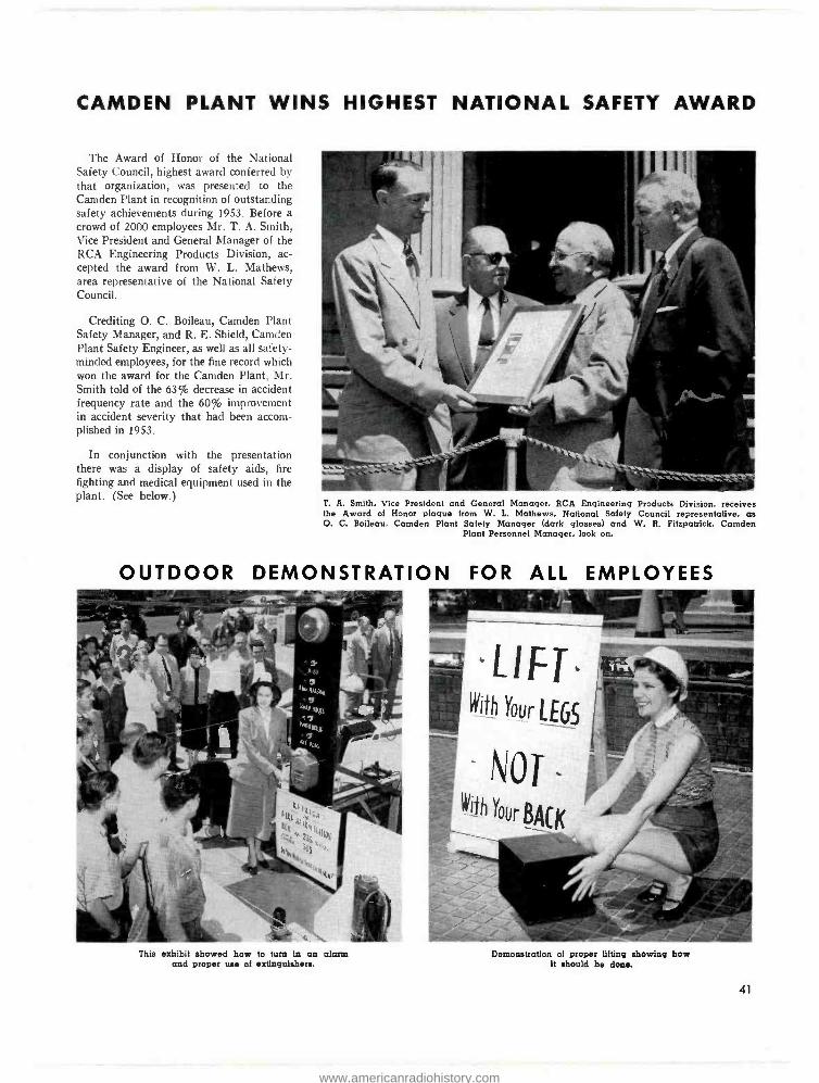
CAMDEN PLANT WINS HIGHEST NATIONAL SAFETY AWARD
The Award of Honor of the National Safety Council, highest award conferred by that organization, was presented to the Camden Plant in recognition of outstanding safety achievements during 1953. Before a crowd of 2000 employees Mr. T. A. Smith, Vice President and General Manager of the RCA Engineering Products Division, ac- cepted the award from W. L. Mathews, area representative of the National Safety Council.
Crediting O. C. Boileau, Camden Plant Safety Manager, and R. E. Shield, Camden Plant Safety Engineer, as well as all safety - minded employees, for the fine record which won the award for the Camden Plant, Mr. Smith told of the 63% decrease in accident frequency rate and the 60% improvement in accident severity that had been accom- plished in 1953.
In conjunction with the presentation there was a display of safety aids, fire fighting and medical equipment used in the plant. (See below.)
T. A. Smith, Vice President and General Manager, RCA Engineering Products Division, receives the Award of Honor plaque from W. L. Mathews, National Safety Council representative, as O. C. Boileau, Camden Plant Safety Manager (dark glasses) and W. R. Fitzpatrick, Camden
Plant Personnel Manager, look on.
OUTDOOR DEMONSTRATION FOR ALL EMPLOYEES
This exhibit showed how to turn In an alarm and proper use of extinguishers.
-LIFT' With Your LEGS
NOT With Your BACK
Demonstration of proper lifting showing how it should he done.
41
www.americanradiohistory.com
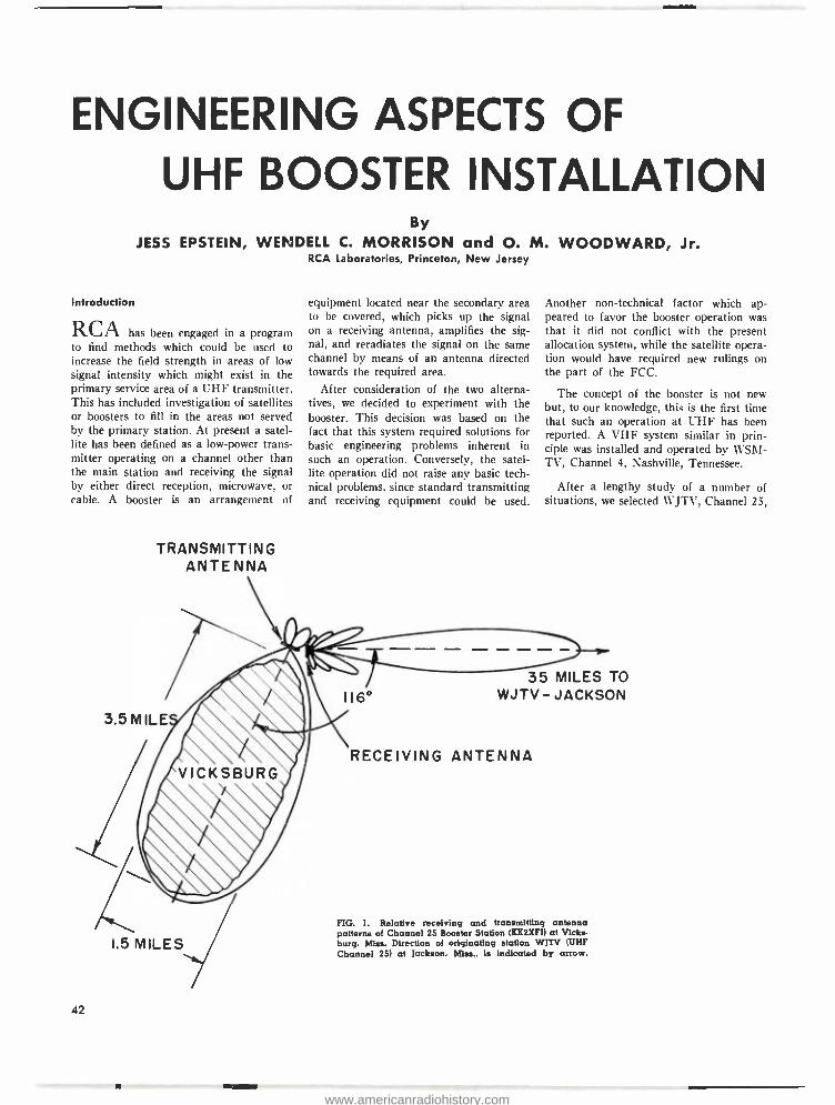
ENGINEERING ASPECTS OF
UHF BOOSTER INSTALLATION By
JESS EPSTEIN, WEN DELL C. MORRISON and O. M. WOODWARD, Jr. RCA Laboratories, Princeton, New Jersey
Introduction
RCAhas been engaged in a program to find methods which could be used to increase the field strength in areas of low signal intensity which might exist in the primary service area of a UHF transmitter. This has included investigation of satellites or boosters to fill in the areas not served by the primary station. At present a satel- lite has been defined as a low -power trans- mitter operating on a channel other than the main station and receiving the signal by either direct reception, microwave, or cable. A booster is an arrangement of
TRANSMITTING ANTENNA
equipment located near the secondary area to be covered, which picks up the signal on a receiving antenna, amplifies the sig- nal, and reradiates the signal on the same channel by means of an antenna directed towards the required area.
After consideration of the two alterna- tives, we decided to experiment with the booster. This decision was based on the fact that this system required solutions for basic engineering problems inherent in such an operation. Conversely, the satel- lite operation did not raise any basic tech- nical problems, since standard transmitting and receiving equipment could be used.
Another non -technical factor which ap- peared to favor the booster operation was that it did not conflict with the present allocation system, while the satellite opera- tion would have required new rulings on the part of the FCC.
The concept of the booster is not new but, to our knowledge, this is the first time that such an operation at UHF has been reported. A VHF system similar in prin- ciple was installed and operated by WSM- TV, Channel 4, Nashville, Tennessee.
After a lengthy study of a number of situations, we selected WJTV, Channel 25,
42
35 MILES TO WJTV - JACKSON
RECEIVING ANTENNA
FIG. 1. Relative receiving and transmitting antenna patterns of Channel 25 Booster Station (KK2XFI) at Vicks- burg, Miss. Direction of originating station WJTV (UHF Channel 25) at Jackson, Miss.. is indicated by arrow.
www.americanradiohistory.com

FIG. 2 (right). The receiving an- tenna for the booster station is a zig -zag type with a gain of 20.5 db. It is mounted on a 100 -foot water tower at a site about two miles northecst of the center of
the city. (See Fig. 3.)
in Jackson, Mississippi, as a likely candi- date for a cooperative effort. This station, with an effective radiated power of 17.7 kw, was said to have trouble in covering Vicksburg, Mississippi, located about 35 miles west of WJTV. The major portion of the town is shielded from the station by a ridge of hills.
A preliminary survey was made in Vicksburg to determine whether there were any receiving sites where a reasonably noise -free picture could be obtained. Sev- eral such locations were found.
The site chosen is located in the far northern end of town. The reason for this choice will he discussed later.
It might be well at this point to dis- cuss the general factors which determine
the components of the booster installation. The input power to the booster amplifier is set by the level required to obtain a noise -free picture. This, of course, will de- termine the required power gain of the receiving antenna for known values of field strength. The pattern of the transmitting antenna is determined by the area to be covered. In the case of Vicksburg a pat- tern was chosen which would provide ap- proximately constant field strength in the required area. The power gain of the trans - mitting antenna can then be computed since it is directly related to the radiation pattern. The effective radiated power (ERP) needed to obtain a given grade of service is then specified. A reasonable esti- mate of this factor can be made from the topography of the given area. The required
power output of the amplifier is then equal to the ERP divided by the antenna gain. The power gain of the amplifier is equal to the ratio of output to input power. A
final factor of vital importance is the magnitude of coupling between the input and output terminals of the amplifier. Severe ghosting of the booster output will occur if this coupling is sufficiently high. Experiments indicate that the attenuation required to obtain a ghost -free picture should be 15 to 20 db higher than the amplifier gain.
The relative location of the Vicksburg area and WJTV with respect to the booster station is shown in Fig. 1. The Vicksburg area is approximately at right angles to the radial between Jackson and Vicksburg.
43
www.americanradiohistory.com
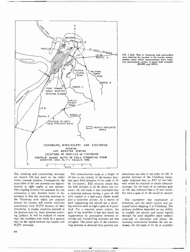
BOOSTER
PROFILE T JTV
116° US ADIAL A
P
/O PORTER
CHAPEL 1 ROAD
POINT TOWARD WHICH BOOSTER ANTENNA IS AIME
RADIAL C
BALDWIN FERRY
ROAD
RADIAL B
A
US 61
HALLS FERRY R0
RADIAL E RADIAL D
ONTOUR OF UNITY FIELD STRENGTH RATIO ® HEAVILY POPULATED
AREAS
VICKSBURG, MISSISSIPPI AND ENVIRONS SHOWING
UHF BOOSTER STATION LOCATIONS OF PROFILES IN VICKSBURG
CONTOUR WHERE RATIO OF FIELD STRENGTHS FROM BOOSTER AND WJTV EQUALS ONE.
o 2 3 MILES
4 5
The receiving and transmitting antennas are located 100 feet apart on the radial drawn towards Jackson. Consequently the main lobes of the two antennas are approx- imately at right angles to one another. The coupling between the antennas for this orientation is low. Another factor of im- portance is that the receiving antennas in the Vicksburg area which are oriented toward the booster will receive minimum interference from WJTV because of their directivity. A similar condition prevails in the Jackson area for those antennas receiv- ing Jackson. It will be realized of course that this condition only holds in a general way for the region between the booster and WJTV antennas.
44
The measurements made at a height of 50 feet in the vicinity of the booster loca- tion gave field strengths of the order of 66 db (µv /meter). This notation means that the field strength is 66 db above one µv/ meter. On this basis it was concluded that a receiving antenna having a gain of 100 with respect to a half -wave dipole would give a noise -free picture. As a matter of good engineering one should use a receiv- ing antenna with as high a gain as is prac- tical. For a required power output, the gain of the amplifier is less and hence the requirements on attenuation between re- ceiving and transmitting antennas are less stringent. The power gain of the transmit- ting antenna as deduced from pattern con-
FIG. 3 (left). Map of Vicksburg and surrounding area showing the location of the booster station. profiles along which measurements were made, and approximate contour of equal field strengths
(KK2XFI and WJTV).
siderations was also in the order of 100. A
general estimate of the Vicksburg topog- raphy indicated that an ERP of one kilo- watt would be required to obtain adequate coverage. On the basis of an antenna gain of 100, this indicated that a 10 watt amt li- fier with a gain of 85 db would be needed.
The equipment was constructed at Princeton, and the entire system was op- erated before shipping it to Vicksburg. The primary problems depended on our ability to amplify the picture and sound signals through the same amplifier chain without cross -talk or distortion and obtain the necessary attenuation between the two an- tennas. On the basis of 85 db of amplifier
www.americanradiohistory.com

FIG. 4 (right). The transmitting antenna for the buster station is a vertical zig -zag type with a power gain of 19.4 db. It is mounted on a 90 -foot pole about 100 feet from receiving antenna site.
gain, 105 db of attenuation was required. 90 db of this was obtained by separating the antennas 100 feet. The additional 15
db of attenuation was obtained by a feed- back loop connected between the input and output terminals of the amplifier.
Vicksburg Tests
The booster site chosen in Vicksburg is
shown in Fig. 2. The receiving antenna was
centered on the east face of a water tower which stood on the premises. The tank shown in Fig. 3 is approximately 30 feet in diameter and 20 feet high. with its cen- ter 110 feet above the ground. The trans- mitting antenna shown in Fig. 4 is set on a wooden tower 100 feet away on a radial
drawn between WJTV and the receiving tower. The center of the transmitting an- tenna is 90 feet above the ground. The test house containing the amplifier was located at the base of the receiving tower. The an- tennas were connected to the amplifier with
-inch Styroflex transmission line. The length of line between the receiving an- tenna and amplifier was 100 feet and be- tween the transmitting antenna and ampli- fier. 200 feet. Provisions were made so that the physical orientation of each antenna. both in azimuth and elevation, could be made on the towers.
The measured input voltage to the am- plifier from WJTV was 4.2 my which is
approximately 10 db greater than the volt-
age obtained for a 50 -foot height of re- ceiving antenna. The attenuation between the antennas was around 105 db. This made the use of a feed -back loop unneces- sary since the difference between the re- quired amplifier gain of 75 db and the 105
db of attenuation is 30 db. Based on the limited observations made in Princeton, and in Vicksburg, it is felt that the major portion of the required attenuation be-
tween antennas be obtained by a combina- tion of spacing between antennas and large reflector screens for either or both an- tennas. A feed -back loop might be used to
obtain some small additional attenuation.
The transmitting antenna was oriented so that the main beam was directed toward
45
www.americanradiohistory.com
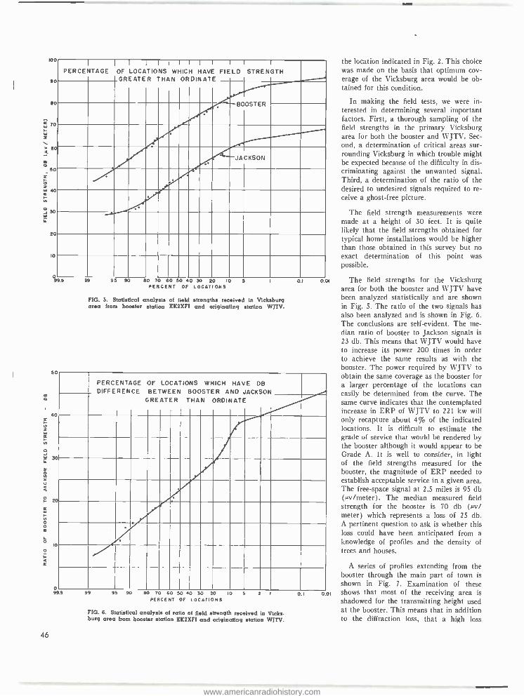
0.0I
001
l00
90
80
70
6c
ó 50
o W 40 er
an
a30
20
lo
o 99 9
PERCENTAGE 1
OF
GREATER
I
LOCATIONS I I
THAN WHICH
1
ORDINATE
I
HAVE
I
FIELD I I
STRENGTH I
BOOSTER
JACKSON
95 90 80 70 60 50 40 30 20 10 5 0.1 PERCENT OF LOCATIONS
FIG. 5. Statistical analysis of field strengths received in Vicksburg area from booster station KK2XFI and originating station WJTV.
50
° 20
cc
ó o m
o 10
o
¢
o 9'
PERCENTAGE DIFFERENCE
OF
BETWEEN GREATER
LOCATIONS
THAN BOOSTER
WHICH AND
ORDINATE
HAVE DB
JACKSON
99 95 90 80 70 60 50 40 30 20 IO PERCENT OF LOCATIONS
2 I O. I
FIG. 6. Statistical analysts of ratio of field strength received in Vicks- burg area from booster station KK2XFI and originating station WITV.
46
the location indicated in Fig. 2. This choice was made on the basis that optimum cov- erage of the Vicksburg area would be ob- tained for this condition.
In making the field tests, we were in- terested in determining several important factors. First, a thorough sampling of the field strengths in the primary Vicksburg area for both the booster and WJTV. Sec- ond, a determination of critical areas sur- rounding Vicksburg in which trouble might be expected because of the difficulty in dis- criminating against the unwanted signal. Third, a determination of the ratio of the desired to undesired signals required to re- ceive a ghost -free picture.
The field strength measurements were made at a height of 30 feet. It is quite likely that the field strengths obtained for typical home installations would be higher than those obtained in this survey but no exact determination of this point was possible.
The field strengths for the Vicksburg area for both the booster and WJTV have been analyzed statistically and are shown in Fig. 5. The ratio of the two signals has also been analyzed and is shown in Fig. 6.
The conclusions are self -evident. The me- dian ratio of booster to Jackson signals is 23 db. This means that WJTV would have to increase its power 200 times in order to achieve the same results as with the booster. The power required by WJTV to obtain the same coverage as the booster for a larger percentage of the locations can easily be determined from the curve. The same curve indicates that the contemplated increase in ERP of WJTV to 221 kw will only recapture about 4% of the indicated locations. It is difficult to estimate the grade of service that would be rendered by the booster although it would appear to be Grade A. It is well to consider, in light of the field strengths measured for the booster, the magnitude of ERP needed to establish acceptable service in a given area. The free -space signal at 2.5 miles is 95 db (vv /meter). The median measured field strength for the booster is 70 db (µv/ meter) which represents a loss of 25 db. A pertinent question to ask is whether this loss could have been anticipated from a knowledge of profiles and the density of trees and houses.
A series of profiles extending from the booster through the main part of town is
shown in Fig. 7. Examination of these shows that most of the receiving area is shadowed for the transmitting height used at the booster. This means that in addition to the diffraction loss, that a high loss
www.americanradiohistory.com
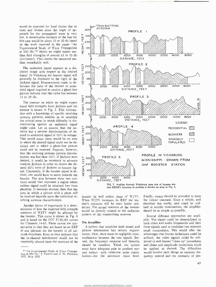
would be expected for local clutter due to trees and houses since the angle of ap- proach for the propagated wave is very low. A conservative estimate of the loss for this case would be about 25 or 30 db based on the work reported in the paper "An Experimental Study of Wave Propagation at 850 Mc. "* Hence we might expect me- dian field strengths of around 65 to 70 db (ev /meter). This checks the measured me- dian remarkably well.
The undesired signal appears as a dis- placed image with respect to the desired signal. In Vicksburg the booster signal will generally be displaced to the right of the Jackson signal. Measurements made to de- termine the ratio of the desired to unde- sired signal required to receive a ghost -free picture indicate that this value lies between 15 to 20 db.
The contour on which we might expect equal field strengths from Jackson and the booster is shown in Fig. 2. This informa- tion with a knowledge of specific receiving antenna patterns enables us to establish the critical areas in which difficulty in dis- criminating against an undesired signal might exist. Let us assume that the an- tenna has a pattern discrimination of de- sired to undesired signal of 10 /1 in voltage. This would mean there would be no area in which the desired signal could not be ob- tained and in which a ghost -free picture could not be received. Suppose, however, that the receiving antenna pattern discrim- ination was less than 10/1. If Jackson were desired, it would be necessary to advance towards Jackson in order to obtain the de- sired 10 /1 ratio of Jackson to booster sig- nal. Conversely, if the booster signal is de- sired, one would have to move towards the booster. The area between these two con- tours would then represent a region where neither signal could be obtained free from ghosting. It becomes obvious then that the area in which a picture with a ghost will be received depends upon the individual re- ceiving antenna characteristics.
Another factor of importance is a deter- mination of how the expected field strength contours of WJTV might be affected by the booster. This curve is shown in Fig. 8 and is based on the FCC F(50,10) curves for Channels 14 -83. These curves are con- servative in that they are based on an ERP of one kilowatt for the booster in all azi- muth directions. Even so they indicate that the co- channel interference would not be materially altered since the contours of the
* "An Experimental Study of Wave Propaga- tion at 850 Mc:' J. Epstein and D. W. Peterson. IRE, May 1953.
400
300
'` 200
t,D 100
w 300 w w
TRANSMITTING ANTENNA
PROFILE I
Ai 41,Ar 2060 4000 6000 8000 10000 12000 14000 16000
DISTANCE, FEET
200 I-
X 100
w x o
300 w
200 r
100 w x
w 300
1`- 200 I- x l7 100 w I 0
PROFILE 2 1/ /11 ¡Al Il , A A NI
I- 300 w l` 200 1=
o 100
x
i
2000 4000 6000 8000 10000 12000 14000 16000 DISTANCE, FEET
. .
6000 8000 10000 12000 14000 16000
LEGEND:
RESIDENTIAL EA
DISTANCE, FEET
PROFILE 4
I i
Iler" /. 4 A 2000 4000 6000 8000
DISTANCE, FEET
PROFILE 5
2000 4000 6000 DISTANCE, FEET
FIG. 7. Profiles through Vicksburg from site of booster sta- tion XX2XFI. Location of profiles is shown on map in Fig. 3.
10000
BUSINESS
SPARSELY POPULATE D
PROFILE IN VICKSBURG
MISSISSIPPI : DRAWN FROM
UHF BOOSTER STATION
booster lie well within those of WJTV. When WJTV increases its ERP the sta- tion's contours will be even better pro- tected. The actual contours of the booster would be directly related to the radiation pattern of the transmitting antenna.
The Amplifier A system that amplifies both sound and
picture information has certain require- ments. First, there must be negligible cross - modulation between the two signals. Sec- ond, the frequency response and linearity should be excellent. Third, the system must have adequate gain to produce nor- mal output -with minimum noise contri- bution -for the minimum input level.
Finally, means should be provided to keep the output constant. Since a simple, and therefore less costly, unit could be util- ized in smaller communities, the amplifier should be as simple as possible.
Several different approaches are avail- able. The signal could be demodulated to both video and audio frequencies and then these signals used to modulate two separate small transmitters. This would offer the advantages that known techniques could be utilized, the video signals could be sub- jected to well -known "clean up" procedures and phase and amplitude corrections could be applied as desired. The difficulties would involve such things as separate fre- quency control and the necessity of pro-
47
www.americanradiohistory.com

/44.------.\-. db ( kw)
VICKSBURG 0
220M/.
185 Ml.
150 Mt.
JACKSON l2.5db( k w)
E. R. P.
FIG. 8. Calculated field strength contours of booster station KK2XFI and originating station WITV. Outer contours of KK2XFI lie well within those of WJTV, indicating booster operation will not increase interference to other stations on same channel.
FIG. 9. This fivestage voltage amplifier is used to amplify the received carrier signal to the level necessary to drive the intermediate power amplifiers.
48
viding a side -band filter with its increased cost and complexity.
A second approach would be to hetero- dyne both sound and picture carriers down to some intermediate frequency, amplify, and then re- heterodyne the signals back to the original frequencies for radiation. The advantages of this approach are the possi- bility of using certain standard compo- nents; for example, a UHF head -end from a receiver and the I -F strip might be modi- fied for such services. Also it might be easier to obtain the required gain at the lower frequency. The disadvantages of this approach are that the extraneous upper side -band produced in the second hetero- dyning must be eliminated from the out- put and that a high -level mixer would have to be developed which carried both the sound and picture signals without produc- ing cross- modulation. An examination of the factors involved rapidly leads to the conclusion that there is no real advantage to the double heterodyning process.
The third approach is to use straight amplification at the carrier frequencies. The principal disadvantage to this method is that little can be done to improve the video signal in passing through the ampli- fier. Therefore, it is essential that any dis- tortions encountered in the amplifier he negligible. Similarly, the system must be sufficiently linear to eliminate any cross - modulation difficulties. This last method is the one we chose to use. In order to pro- vide a linear system, we planned to use Class A amplification throughout.
The system developed utilizes in cas- cade a low -noise pre -amplifier, a variable - gain voltage amplifier, several additional voltage amplifiers, and then two coaxial cavities for the IPA and power amplifier stages. Automatic gain control operates from the output -line voltage to control the variable -gain amplifiers.
A number of design arrangements for the low -level voltage amplifiers were con- sidered. The method chosen was especially attractive because of the adpatability to operation over the entire UHF band. It is
a grounded -grid stage utilizing a type 6AN4 tube. The input circuit is not ad- justable, but the component values have been chosen to tune the input impedance to 75 ohms for Channel 25. The output circuit uses a / -wave line with capacitive loading available to tune the lower UHF channels. Output coupling is provided by a series capacitor appropriately tapped on the plate line to give a mid -band gain of 10 db and a bandwidth flat within 1' /2 db over a 6- megacycle channel. The noise
www.americanradiohistory.com
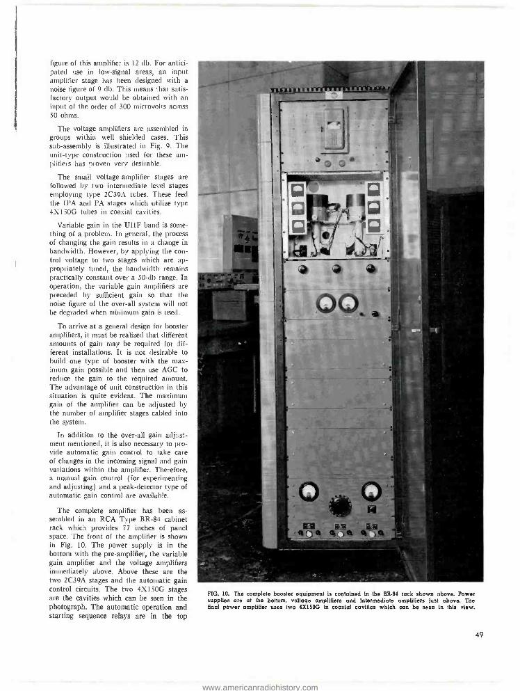
figure of this amplifier is 12 db. For antici- pated use in low- signal areas, an input amplifier stage has been designed with a noise figure of 9 db. This means that satis- factory output would be obtained with an input of the order of 300 microvolts across 50 ohms.
The voltage amplifiers are assembled in groups within well shielded cases. This sub -assembly is illustrated in Fig. 9. The unit -type construction used for these am- plifiers has proven very desirable.
The small voltage -amplifier stages are followed by two intermediate level stages employing type 2C39A tubes. These feed the IPA and PA stages which utilize type 4X150G tubes in coaxial cavities.
Variable gain in the UHF band is some- thing of a problem. In general, the process of changing the gain results in a change in bandwidth. However, by applying the con- trol voltage to two stages which are ap- propriately tuned, the bandwidth remains practically constant over a 50 -db range. In operation, the variable gain amplifiers are preceded by sufficient gain so that the noise figure of the over -all system will not be degraded when minimum gain is used.
To arrive at a general design for booster amplifiers, it must be realized that different amounts of gain may be required for dif- ferent installations. It is not desirable to build one type of booster with the max- imum gain possible and then use AGC to reduce the gain to the required amount. The advantage of unit construction in this situation is quite evident. The maximum gain of the amplifier can be adjusted by the number of amplifier stages cabled into the system.
In addition to the over -all gain adjust- ment mentioned, it is also necessary to pro- vide automatic gain control to take care of changes in the incoming signal and gain variations within the amplifier. Therefore, a manual gain control (for experimenting and adjusting) and a peak- detector type of automatic gain control are available.
The complete amplifier has been as- sembled in an RCA Type BR -84 cabinet rack which provides 77 inches of panel space. The front of the amplifier is shown in Fig. 10. The power supply is in the bottom with the pre -amplifier, the variable gain amplifier and the voltage amplifiers immediately above. Above these are the two 2C39A stages and the automatic gain control circuits. The two 4X150G stages are the cavities which can be seen in the photograph. The automatic operation and starting sequence relays are in the top
FIG. 10. The complete booster equipment is contained in the BR.84 rack shown above. Power supplies are at the bottom. voltage amplifiers and intermediate amplifiers just above. The final power amplifier uses two 4X150G in coaxial cavities which can be seen in this view.
49
www.americanradiohistory.com

FIG. 11. The overall booster amplifier has a gain of the order of 100 db, and a bandwidth essentially flat over 6 megacycles. A typical response curve is shown above.
FIG. 12. This is a closeup view of the zig -zag receiving antenna before installation on the water tower shown in Fig. 2. It has a measured beam width of 16° (both vertical and horizontal) and a gain of 20.5 db.
50
panel. A total of 16 stages are built into the unit, but only 14 stages have been utilized at any one time. Under this con- dition, the amplifier is capable of a gain of the order of 100 db and a bandwidth essentially flat over 6 megacycles. This is
obtained by stagger tuning. A typical re- sponse curve of the amplifier is shown in
Fig. 11.
The performance of the amplifier in Vicksburg has been most gratifying. There was no indication of cross- modulation of either the sound into the picture or syn- chronizing pulses into the sound. Test pat- terns observed with a well- aligned receiver directly on the receiving antenna and then on the output of the amplifier showed no appreciable change in resolution or gray scale.
General Antenna Design Considerations
The zig -zag type of antenna was used in the design of both the transmitting and receiving arrays because of the simplicity of construction. Basically, the radiator ele- ments consists of a long, single wire bent at half -wave intervals into the form of a vertical zig -zag. The plane of this array is
spaced sufficiently distant from a vertical sheet reflector so that the line radiates in addition to functioning as a transmission line. Since a phase reversal occurs every half -wave, the horizontal components of the zig -zag currents flow in the same direc- tion and the vertical components alternate in direction. Hence the zig -zag operates essentially as an array of in- phase, hori- zontal dipoles stacked vertically to produce a narrow elevation pattern.
A considerable number of experimental measurements have been made on various types of zig -zag arrays. Based on this work, a few generalized observations on the design problems follow.
The vertical aperture of the array in- creases with the inclination angle of the half -wave elements for a given wire length. However, this gives a greater ratio of ver- tical to horizontal current components, re- sulting in undesirably large vertically - polarized radiation at certain elevation angles.
Conversely, lowering the inclination angle decreases the vertically- polarized radiation but reduces the vertical aperture. If the aperture is increased for this case by adding to the wire length, the ampli- tude distribution along the array falls off rapidly.
The amplitude distribution is also closely related to the spacing between the zig -zag and screen reflector. For large spacings and
www.americanradiohistory.com

FIG. 13. Closeup of the vertical sig -sag transmitting antenna. It has a horizontal beam width of 64° and a vertical beam width of 3.4 °.
long arrays, most of the radiation occurs from the first few radiators, resulting in poor aperture illumination. For very small spacings, the zig -zag is essentially a trans- mission line with little radition except near the far end.
Therefore it is seen that a compromise adjustment of the various array parameters is necessary for antennas designed for a minimum number of feed points.
From measurements on various types of zig -zags, an element inclination angle of 45° and a screen spacing of approximately
wavelength have been found to be rea- sonable design values for antenna bays of about 6 or 8 wavelengths in height. Al- though the physical length of each zig -zag element is affected somewhat by the type of standoff insulator used and size of wire. in general the length is within a few per- cent of a free -space half- wavelength.
For arrays made of such bay sections, stacked vertically, four times the array height in wavelengths gives an approxima-
tion of the power gain relative to a half - wave dipole. This value is about 2/3 of the power gain that would be produced by a perfect current sheet of the same dimensions.
Photographs of the receiving and trans- mitting antennas are shown in Figs. 12
and 13. The receiving antenna has a beam width for both azimuth and elevation of 16° at % field strength, a power gain of 20.5 db with respect to a half -wavelength dipole, and a VSWR of less than 1.05 throughout the channel. The transmitting antenna has a beam width of 64° in the azimuth and 3.4° in the elevation planes for % field strength, a power gain of 19.4 db, and a VSWR of less than 1.1 through- out the channel.
Conclusions
The measurements and observations of the performance of the booster at Vicks- burg successfully demonstrate the feasi- bility of this method in covering a low - signal area. The performance obtained with
the components of the booster system indi- cate that there are no inherent technical difficulties in the approach used. The project is further confirmation that a good engineering estimate of the ERP required to establish a given grade of service can be made once the topography of the given area is known.
Acknowledgment We wish to express our sincere appre-
ciation to the Mississippi Publishing Cor- poration for its generous cooperation in this project. We are greatly indebted to J. R. Whitworth, Chief Engineer, and S. J. Parks, Assistant Chief Engineer, of WJTV for the untiring effort and interest they have given to this experiment. The success of a project of this scope is dependent on the work of many individuals. In particular we wish to thank Dr. G. H. Brown for his over -all guidance, K. Karstad, D. W. Pererson, J. B. Rankin, of the RCA Labor- atories, and E. W. Sattler, Jr., of the RCA Service Company, for their contributions in building and testing this system.
51
www.americanradiohistory.com

COMMERCIAL ASPECTS OF
UHF BOOSTER OPERATION By
L. W. HAESELER, N. McNAUGHTEN and L. J. WOLF
The preceding article' has described in detail the experimental Channel 25 Sat- ellite (booster) installed by the RCA Laboratories Division (in conjunction with WJTV) at Vicksburg, Mississippi. The ex- tensive field strength measurements which were made in the Vicksburg area proved the technical feasibility of using a UHF Booster as a means of providing adequate field strength in a low -signal area.
In order to get an idea of the commercial prospects of booster operation, the authors spent several days at Vicksburg. We con- sidered the practical aspects of the installa- tion, observed reception under typical home conditions, and talked to servicemen, deal-
RCA Engineering Products Division
ers, and station people. Here's what we found out.
First, as to how well it works. In order to get the feel of booster reception in Vicksburg we rode around the city with Mr. Epstein in the RCA Laboratories' field unit observing the received signal in various areas. In addition we looked at pictures in several fixed locations in the city including a dealer's store as well as in individuals' homes.
The most striking feature of the KK2XFI (WJTV Booster) operation was the excellent, noise -free reception obtained with relatively inexpensive antenna instal- lations. Vicksburg is about 40 miles from
FIG. I. In the Vicksburg area tall masts with multiple element antennas are usually required to get satisfactory reception of nearest television stations located in Jackson about 40 miles distant.
52
the nearest TV stations at Jackson. In addition, it is shadowed by several ridges which lie between. Thus, most receiver in- stallations (even for VHF) are provided with elaborate arrays on tall poles, such as seen in Fig. 1. In contrast, the Channel 25
Booster could be received at most points in
Vicksburg with a simple bow -tie antenna located just above the roof.
In order to get an idea of comparable reception of booster and direct signals a series of tests was made in a dealer's store. The high antenna array normally used by this dealer for reception of Vicksburg sta- tions is shown in Fig. 2. For this series of tests a rotatable bow -tie -and -reflector an- tenna was located just above the roof of the building, as can be seen in Fig. 2.
The reception direct from WJTV on the high antenna was satisfactory, although it was rather snowy. When the receiver was connected to the bow -tie antenna and the latter rotated to the direction of WJTV the picture was somewhat more snowy, as seen in Fig. 3. However, when the bow - tie was rotated to the direction of the KK2XFI booster an excellent picture was obtained as shown in Fig. 4. The effect of the receiving antenna directivity can be seen in Fig. 5 which is a picture from the screen when the bow -tie direction is in between booster and direct. It was noted by the observers that it was rather difficult to orient the antenna to obtain this mul- tiple effect as one signal or the other tended to predominate.
From this test and from the evaluation made on home receivers, including a re- ceiver mounted in a station wagon as well as those in use in homes, it was concluded that a satellite installation of this type can be successful in providing improved service in most instances and it is evident
t "Engineering Aspects of UHF Booster Op- eration," by J. Epstein, W. C. Morrison and O. M. Woodward, BROADCAST News No. 80, July -Aug. 1954.
www.americanradiohistory.com

FIG. 2. Antenna array used by dealer in downtown Vicksburg to receive stations in Jackson. Bow -tie UHF antenna just above roof was installed for tests described here. It provided excellent reception of booster station signals.
that it provides a satisfactory and eco- nomical method of filling in shadowed areas. In each proposed case, however, a survey must be made to determine the feasibility for the specific locality, since each application is unique.
Planning a Satellite (Booster)
The work required in planning a satel- lite must be just as thorough as that done for a main station, and should preferably be done by an engineering consultant. However, a preliminary survey will be of considerable value in determining the feas- ibility in each specific case. The recom- mended steps are as follows:
First consideration is whether or not satellite operation is desirable (even if practical). Economics and competition will be the main considerations. The area to be served obviously will have to be large enough to justify (in terms of potential
FIG. 3 (right, top). Picture received direct from WJTV, Jackson, with bow tie an- tenna shown in Fig. 2 pointed
toward Jackson.
FIG. 4 (right, center). Picture received from booster station KK2XFI with the bow -tie an- tenna shown in Fig. 2 directed
toward booster.
FIG. 5 (right, bottom). Picture received when bow -tie an- tenna of Fig. 2 is oriented about half-way between di- rections of WJTV (direct) and
KK2XFI (booster).
53
www.americanradiohistory.com
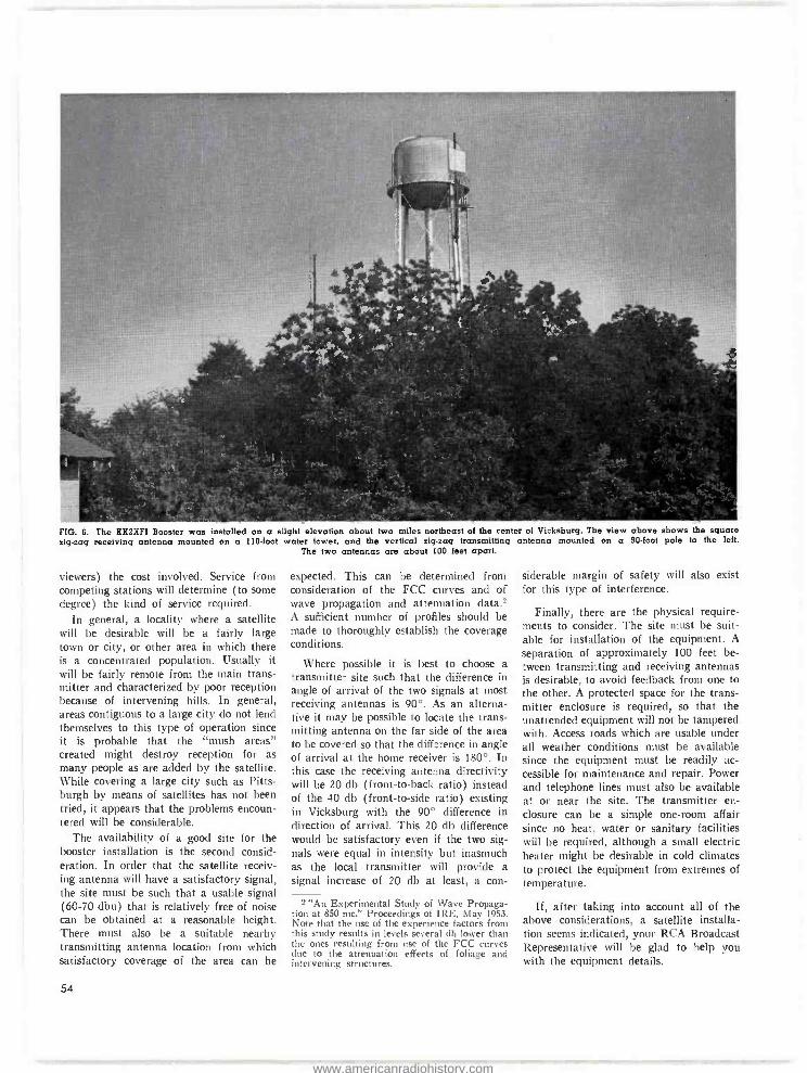
FIG. 6. The KX2XFI Booster was installed on a slight elevation about two miles northeast of the center of Vicksburg. The view above shows the square zigzag receiving antenna mounted on a 110-foot water tower, and the vertical sig -sag transmitting antenna mounted on a 90 -foot pole to the left.
The two antennas are about 100 feet apart.
viewers) the cost involved. Service from competing stations will determine (to some degree) the kind of service required.
In general, a locality where a satellite will be desirable will be a fairly large town or city, or other area in which there is a concentrated population. Usually it will be fairly remote from the main trans- mitter and characterized by poor reception because of intervening hills. In general, areas contiguous to a large city do not lend themselves to this type of operation since it is probable that the "mush areas" created might destroy reception for as many people as are added by the satellite. While covering a large city such as Pitts- burgh by means of satellites has not been tried, it appears that the problems encoun- tered will be considerable.
The availability of a good site for the booster installation is the second consid- eration. In order that the satellite receiv- ing antenna will have a satisfactory signal, the site must be such that a usable signal (60 -70 dbu) that is relatively free of noise can be obtained at a reasonable height. There must also be a suitable nearby transmitting antenna location from which satisfactory coverage of the area can be
54
expected. This can be determined from consideration of the FCC curves and of wave propagation and attenuation data.2 A sufficient number of profiles should be made to thoroughly establish the coverage conditions.
Where possible it is best to choose a transmitter site such that the difference in angle of arrival of the two signals at most receiving antennas is 90 °. As an alterna- tive it may be possible to locate the trans- mitting antenna on the far side of the area to be covered so that the difference in angle of arrival at the home receiver is 180 °. In this case the receiving antenna directivity will be 20 db (front -to -back ratio) instead of the 40 db (front -to -side ratio) existing in Vicksburg with the 90° difference in direction of arrival. This 20 db difference would be satisfactory even if the two sig- nals were equal in intensity but inasmuch as the local transmitter will provide a signal increase of 20 db at least, a con-
2 "An Experimental Study of Wave Propaga- tion at 850 mc," Proceedings of IRE. May 1953. Note that the use of the experience factors from this study results in levels several db lower than the ones resulting from use of the FCC curves due to the attenuation effects of foliage and intervening structures.
siderable margin of safety will also exist for this type of interference.
Finally, there are the physical require- ments to consider. The site must be suit- able for installation of the equipment. A
separation of approximately 100 feet be- tween transmitting and receiving antennas is desirable, to avoid feedback from one to the other. A protected space for the trans- mitter enclosure is required, so that the unattended equipment will not be tampered with. Access roads which are usable under all weather conditions must be available since the equipment must be readily ac- cessible for maintenance and repair. Power and telephone lines must also be available at or near the site. The transmitter en- closure can be a simple one -room affair since no heat, water or sanitary facilities will be required, although a small electric heater might be desirable in cold climates to protect the equipment from extremes of temperature.
If, after taking into account all of the above considerations, a satellite installa- tion seems indicated, your RCA Broadcast Representative will be glad to help you with the equipment details.
www.americanradiohistory.com
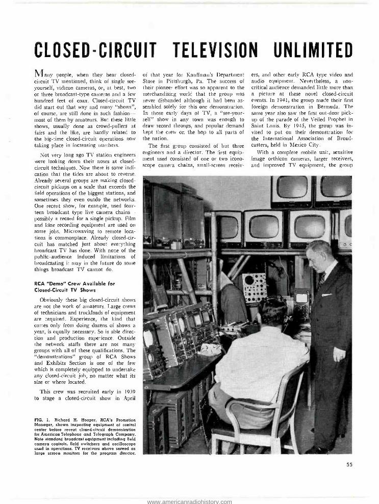
CLOSED-CIRCUIT TELEVISION UNLIMITED Many people, when they hear closed - circuit TV mentioned, think of single see - yourself, vidicon cameras, or, at best, two or three broadcast -type cameras and a few hundred feet of coax. Closed- circuit TV did start out that way and many "shows ", of course, are still done in such fashion - most of them by amateurs. But these little shows, usually done as crowd -pullers at fairs and the like, are hardly related to the big -time closed- circuit operations now taking place in increasing numbers.
Not very long ago TV station engineers were looking down their noses at closed - circuit techniques. Now there is some indi- cation that the tides are about to reverse. Already several groups are making closed - circuit pickups on a scale that exceeds the field operations of the biggest stations, and sometimes they even outdo the networks. One recent show, for example, used four- teen broadcast type live camera chains - possibly a record for a single pickup. Film and kine recording equipment are used on some jobs. Microwaving to remote loca- tions is commonplace. Already closed -cir- cuit has matched just about everything broadcast TV has done. With none of the public- audience induced limitations of broadcasting it may in the future do some things broadcast TV cannot do.
RCA "Demo" Crew Available for Closed- Circuit TV Shows
Obviously these big closed- circuit shows are not the work of amateurs. Large crews of technicians and truckloads of equipment are required. Experience, the kind that comes only from doing dozens of shows a year, is equally necessary. So is able direc- tion and production experience. Outside the network staffs there are not many groups with all of these qualifications. The "demonstrations" group of RCA Shows and Exhibits Section is one of the few which is completely equipped to undertake any closed- circuit job, no matter what its size or where located.
This crew was recruited early in 1939 to stage a closed -circuit show in April
FIG. 1. Richard H. Hooper, RCA's Promotion Manager, shown inspecting equipment at control center before recent closed- circuit demonstration for American Telephone and Telegraph Company. Note standard broadcast equipment including field camera controls, field switchers and oscilloscope used in operations. TV receivers above served as large screen monitors for the program director.
of that year for Kauffman's Department Store in Pittsburgh, Pa. The success of their pioneer effort was so apparent to the merchandising world that the group was never disbanded although it had been as- sembled solely for this one demonstration. In those early days of TV, a "see -your- self" show in any town was enough to draw record throngs, and popular demand kept the crew on the hop to all parts of the nation.
The first group consisted of but three engineers and a director. The first equip- ment used consisted of one or two icono - scope camera chains, small- screen receiv-
ers, and other early RCA type video and audio equipment. Nevertheless, a non- critical audience demanded little more than a picture at these novel closed- circuit events. In 1941, the group made their first foreign demonstration in Bermuda. The same year also saw the first out -door pick- up of the parade of the Veiled Prophet in Saint Louis. By 1945, the group was in- vited to put on their demonstration for the International Association of Broad- casters, held in Mexico City.
With a complete mobile unit, sensitive image orthicon cameras, larger receivers, and improved TV equipment, the group
55
www.americanradiohistory.com
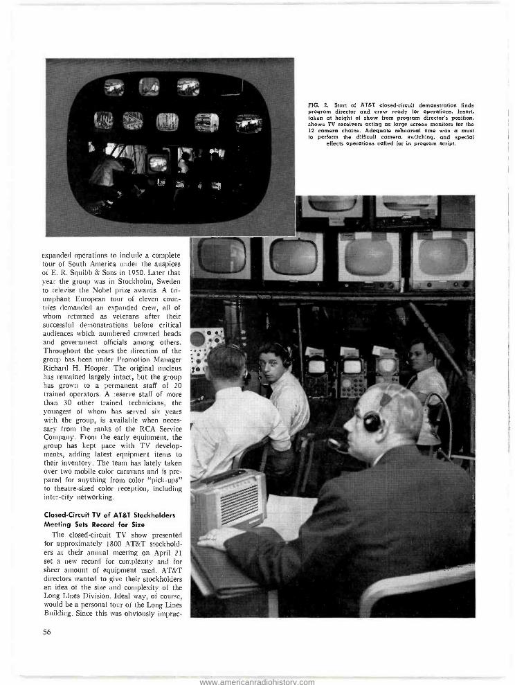
FIG. 2. Start of AT &T closed- circuit demonstration finds program director and crew ready for operations. Insert, taken at height of show from program director's position, shows TV receivers acting as large screen monitors for the 12 camera chains. Adequate rehearsal time was a must to perform the difficult camera, switching, and special
effects operations called for in program script.
expanded operations to include a complete tour of South America under the auspices of E. R. Squibb & Sons in 1950. Later that year the group was in Stockholm, Sweden to televise the Nobel prize awards. A tri- umphant European tour of eleven coun- tries demanded an expanded crew, all of whom returned as veterans after their successful demonstrations before critical audiences which numbered crowned heads and government officials among others. Throughout the years the direction of the group has been under Promotion Manager Richard H. Hooper. The original nucleus has remained largely intact, but the group has grown to a permanent staff of 20 trained operators. A reserve staff of more than 30 other trained technicians, the youngest of whom has served six years with the group, is available when neces- sary from the ranks of the RCA Service Company. From the early equipment, the group has kept pace with TV develop- ments, adding latest equipment items to their inventory. The team has lately taken over two mobile color caravans and is pre- pared for anything from color "pick -ups" to theatre -sized color reception, including inter -city networking.
Closed- Circuit TV of AT&T Stockholders Meeting Sets Record for Size
The closed- circuit TV show presented for approximately 1800 AT &T stockhold- ers at their annual meeting on April 21 set a new record for complexity and for sheer amount of equipment used. AT &T directors wanted to give their stockholders an idea of the size and complexity of the Long Lines Division. Ideal way, of course, would be a personal tour of the Long Lines Building. Since this was obviously imprac-
56
www.americanradiohistory.com

tical they hit on the idea of giving stock- holders the tour '`by TV ". RCA's Show Division was called in to help plan the show and carry out all the technical aspects.
AT &T operations presented a polished 24- minute live show which afforded the share owners a clearer and more concise picture of the operation of the Long Lines Division of their company than they could have obtained by actually touring the area. The program was relayed from the Long Lines Building at Sixth Avenue and Canal Street to AT &T headquarters, through the company's own cable facili- ties. The program formed an entertaining as well as educational interlude while bal- lots were being counted at the company's annual meeting.
Fourteen image orthicon cameras were required for this show, ten being set up in strategic and widely separated locations in the 29 -story Long Lines Building, two in the production studio on the 15th floor. and two in the share holder's meeting room at 195 Broadway. Audio and lighting equipment were set up with the cameras at each location. These required thousands of feet of cabling, extension cords, plugs. sockets and related facilities, many of which were provided by the telephone
FIG. 3. Two camera- chains in AT &T stock- owners room relayed proceedings to overflow audiences in five nearby rooms at 196 Broadway and also cut into televised program at Long Lines building during final sequence. The cameras are shown on right. Note TV receivers lining room, and RCA PT -100 large screen theatre TV equipment on far balcony which brought TV show to stockholders. Theatre TV projectors on both balconies projected program on two large screen (seen above cam- eraman) which were lowered at time of show.
FIG. 4. Secondary control center for AT &T tele- vision demonstration was located in this small "studio" off the balcony of large share owners meeting room. Two camera chains following events at the annual business meeting were switched to overflow rooms and cut into the Long Lines program with standard broadcast
equipment.
57
www.americanradiohistory.com
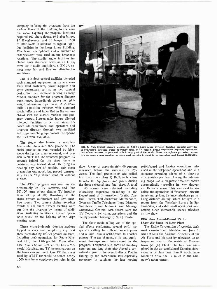
company to bring the programs from the various floors of the building to the con- trol room. Lighting the program locations required 102 photo- floods, 26 Steber lamps, 17 Kleigl- scoops, and 30 lamps of 1500 to 2000 -watts in addition to regular light- ing facilities in the Long Lines Building. Five boom microphones and a number of "Starmakers" were used on the broadcast locations. The studio audio facilities in- cluded such standard items as an OP -6, three OP -7 audio amplifiers, a BN -2A re- mote amplifier, and line and distribution amplifiers.
The 15th -floor control facilities included such standard equipment as camera con- trols, field switchers, power supplies and sync generators, set up at two control desks. Fourteen receivers serving as large camera monitors for the program director were ranged immediately above on light- weight aluminum pipe racks. A custom - built 14- position switcher with standard special effects and fader tied in the various chains with the master monitor and pro- gram output. Sixteen mike inputs allowed intercom facilities to be maintained be- tween all cameramen and operators and program director through two modified field type switching equipments. Telephone facilities were available.
The studio also boasted a complete 16mm film chain and slide projector. The entire production was recorded by kine- scope during the dress rehearsal, and Sta- tion WNBT ran the recorded program 45 seconds behind the live show ready to cut -in at any instant should the program develop any sort of trouble. This extra precaution was novel, but proved unneces- sary as the "big show" went off without a hitch.
The AT &T program was seen on ap- proximately 25 TV receivers and four PT -100 large screen theatre TV installa- tions set up at 195 Broadway in the share owners auditorium and five over- flow rooms. Two camera chains recording events at the share owners meeting were cut into the program by means of addi- tional switching facilities at a small opera- tions studio off the balcony of the large meeting room.
These closed- circuit demonstrations topped in scope and complexity any past show presented by RCA's promotion team, including their operations for Foote Min- eral Co., the Lithographic Foundation, Electrolux Vacuum Cleaner, the Lewis Me- morial Hospital, and TV demonstrations on the European continent. One TV chain was used by AT &T for weeks to screen nearly 1000 telephone employees for roles in the
58
FIG. 5. This typical camera location in AT &T's Long Lines Division Building brought activities in company's overseas traffic operating room to TV screen. Fhone supervisor explains operations that allow business or personal calls to any part of the world. Boom microphone picked-up narra- tive as camera was required to move past narrator to close in on operators and board operations.
show. A cast of approximately 60 persons rehearsed before the cameras for 2% weeks. The final presentation also called into force more than 50 RCA technicians to man the equipment and props during the dress rehearsal and final show. A total of 45 scenes were televised including interesting sequences picked -up in the Department of Information, Traffic Con- trol Bureau, Toll Switching Maintenance, Overseas Traffic Telephone, Long Distance Switchboard and Network and Message Microwave Centers. Also shown were the TV Network Switching operations and the Teletypewriter Message (TWX) Center.
The show made telling use of the spe- cial effects equipment, several script se- quences calling for difficult superimposes and a fade from a split- screen to another picture. The use of maps, stills and equip- ment close -ups were interspersed in the program. Telephoto lens shots of building exteriors and long shots also played a con- siderable part in the overall effects. Precise timing by the cameramen was especially necessary in catching the fast moving
switchboard and keying operations tele- vised in the telephone operations and in a sequence revealing effects of a blow -out of a grasshopper fuse. Among the interest- ing props was a magnetic "mouse" shown automatically threading its way through an electronic maze. This was used to vis- ualize the operations of "memory" circuits in setting up long distance telephone paths. Long distance dialing, which brought in a report from the Weather Bureau in San Francisco, and cable vault operations were among other memorable scenes televised on the show.
RCA Uses Closed-Circuit TV to Show Air Force Its New Plant
The Radio Corporation of America itself used closed- circuit television on June 7,
when it took the Assistant Secretary of the Air Force and his staff by television on an inspection tour of the restricted Moores- town (N. J.) Plant. The tour was com- pleted in the air -conditioned Camden show- room in far less time than it would have taken to drive the 12 miles to the com- pany's radar center.
www.americanradiohistory.com

Operation "Moorestown" was hatched Wednesday, June 2, when it was learned the Air Chief and staff had to meet a tight time schedule on their itinerary of defense plants in the Philadelphia area. Teamwork of many RCA departments produced script, a finished program, TV installation, and FCC license to microwave in four short days. The equivalent of a
two hour tour was reduced to a ten minute TV travelogue. Every major plant area was clearly seen on two large- screen home receiving sets in the RCA Camden show- room.
The program was relayed from Moores- town by means of RCA studio to transmit- ter link microwave equipment. The four - foot parabolic antenna on the receiving roof was mounted on a tripod and weighted with sandbags. A temporary 70 -foot an- tenna tower was erected upon the roof of the Moorestown plant to clear obstacles over the 12 miles of intervening terrain.
FIG. 7. Floor plan of RCA's Moorestown Radar Plant showing facilities and location of ten closed - circuit television camera chains. Cameras 7 and 8
were on mobile units to cover outdoor areas. Camera 3 was used to project stills, maps and other props which served to explain lesser facili- ties such as cafeteria, dispensary, offices and power plant. Remaining cameras completely cov-
ered plant's manufacturing facilities.
FIG. 6. Microwave installation used for closed - circuit TV tour of Moorestown Plant staged for nation's ranking air chiefs. Above, 4 -toot para- bolic antenna is moored to roof of RCA's general office building in Camden; below, temporary 70- foot tower on Moorestown Plant from which sig-
nals were relayed.
L
l
e
e
e 3
-171
LOI
1
nOwla
1
OPIKe
7-1
TOMS
MOORESTOWN ENGINEERING
PLANT
D-3110837
59
www.americanradiohistory.com

41
15 FIG. 8. Ten cameras (keyed to positions used during show and located on floor plan Fig. 7) proved excellent means of presenting manufacturing activities yet maintaining plant security regulations since cameramen easily "cut out" security areas and operations. From positions 1 and 8
early outdoor sequences moved on to position 10 where gaining security clearance to radar plant formed opening indoor sequence in RCA plant tour. Camera could follow action down corridor to model shop where camera 4 took over. Cameras 5, 6, 3 and 9 continued the manu. factoring cycle, with latter two cameras also doubling to show "stills" when called for in script. Camera 2 had , "birds eye" spot in high bay engineering lab area, while camera 7 on mobile truck fork -lift proved a vantage point from which to - shoot "" trucking areas, outdoor facilities,
and final sequence leaving the plant.
9
2 &3/
www.americanradiohistory.com
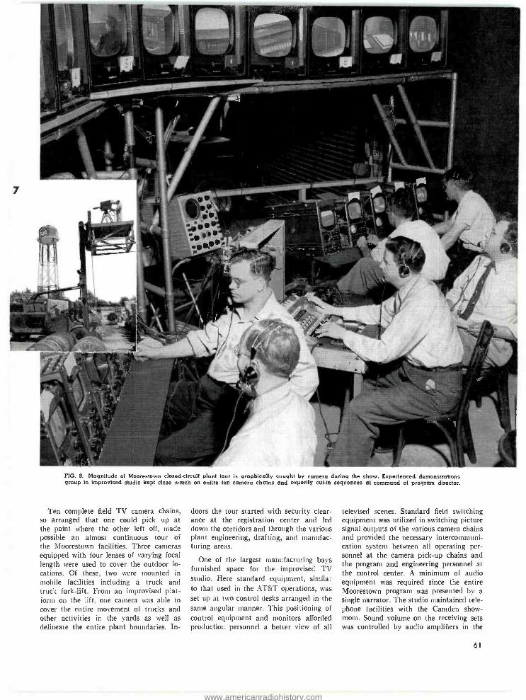
FIG. 9. Magnitude of Moorestown closed- circuit plant tour is graphically caught by camera during the show. Experienced demonstrations group in improvised studio kept close watch on entire ten camera chains and expertly cut -in sequences at command of program director.
Ten complete field TV camera chains, so arranged that one could pick up at the point where the other left off, made possible an almost continuous tour of the Moorestown facilities. Three cameras equipped with four lenses of varying focal length were used to cover the outdoor lo- cations. Of these, two were mounted in mobile facilities including a truck and truck fork -lift. From an improvised plat- form on the lift, one camera was able to cover the entire movement of trucks and other activities in the yards as well as delineate the entire plant boundaries. In-
doors the tour started with security clear- ance at the registration center and led down the corridors and through the various plant engineering, drafting, and manufac- turing areas.
One of the largest manufacturing bays furnished space for the improvised TV studio. Here standard equipment, similar to that used in the AT &T operations, was set up at two control desks arranged in the same angular manner. This positioning of control equipment and monitors afforded production personnel a better view of all
televised scenes. Standard field switching equipment was utilized in switching picture signal outputs of the various camera chains and provided the necessary intercommuni- cation system between all operating per- sonnel at the camera pick -up chains and the program and engineering personnel at the control center. A minimum of audio equipment was required since the entire Moorestown program was presented by a
single narrator. The studio maintained tele- phone facilities with the Camden show- room. Sound volume on the receiving sets was controlled by audio amplifiers in the
61
www.americanradiohistory.com
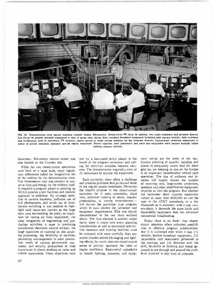
FIG. 10. Demonstration crew shown manning controls during Moorestown closed -circuit TV show. In addition, two audio engineers and program director (not shown in picture) operated equipment to rear of group seen above. Note standard broadcast equipment including field camera controls, field switchers and oscilloscope used in operations. TV receivers above served as large screen monitors for the program director. Custom -built switching equipment in
center of picture combines standard special effects equipment. Power supplies, sync generators and other test equipment were housed beneath tables holding camera controls.
showroom. Microwave control center was also located at the Camden site.
While the two closed -circuit operations were both on a large scale, many signifi- cant differences called for imaginative use of the medium by the demonstration crew. The Moorestown tour was planned to con- serve time and energy by the military staff. It required a program aimed at pointing up RCA's superior plant facilities and realistic approach to problems. By strategic selec- tion of camera locations, judicious use of still photographs, and lavish use of inter - camera switching it was possible to high- light such important matters as the large open area surrounding the plant, so impor- tant for testing air force equipment; the close integration of engineering and pro- duction activities, a must in producing complicated electronic control devices; the large quantities of material on site await- ing processing; the flexibility of facilities, permitting rearrangement to meet produc- tion needs of various government con- tracts; and security precautions of vital importance in plants working on radar and missile equipments. These objectives were
62
met by a fast -paced script placed in the hands of the program announcer and call- ing for thirty -six switches between cam- eras. The demonstration required a crew of 22 technicians to operate the equipment.
Each particular show offers a challenge and presents problems that go beyond those of the regular studio broadcasts. Obviously the client's purpose in the closed- circuit operation -be it sales promotion, plant tour, technical training or study, popular presentation, or merely entertainment - will dictate the particular type program which in turn decides the personnel and equipment requirements. This was clearly demonstrated in the two tours outlined above. The time element is another major factor since it enters into every planning consideration as well as operations activity. Site locations and existing facilities must be reckoned with more carefully than any studio director selects his staging and light- ing effects, for rarely does the closed- circuit arena of activity approach the ideal of studio conditions. Resourceful makeshifts to benefit lighting, acoustics, and equip-
ment set -up are the order of the day. Careful planning of standby facilities and spares to adequately assure that the show goes on, yet keeping an eye on the budget is an important consideration behind each operation. The size of audience and lo- cation will largely dictate the number of receiving sets, large- screen projectors, speakers and other amplification equipment required to view the program. But whether the particular show requires equipment valued at more than $350,000 as was the case in the AT &T operations, or a few thousands as is necessary with a one cam- era- chain, it demands the same facile and dependable equipment that has advanced commercial broadcasting.
Today there is no doubt that closed - circuit television offers unlimited possibil- ities in effective program presentations. But it is unlimited only when it has (1) reliable, flexible broadcast equipment, (2) dependable and resourceful personnel at the controls, and (3) directors with the skill, flexibility of thinking and visual ap- proach to see through and around the prob- lems involved in any kind of program.
www.americanradiohistory.com
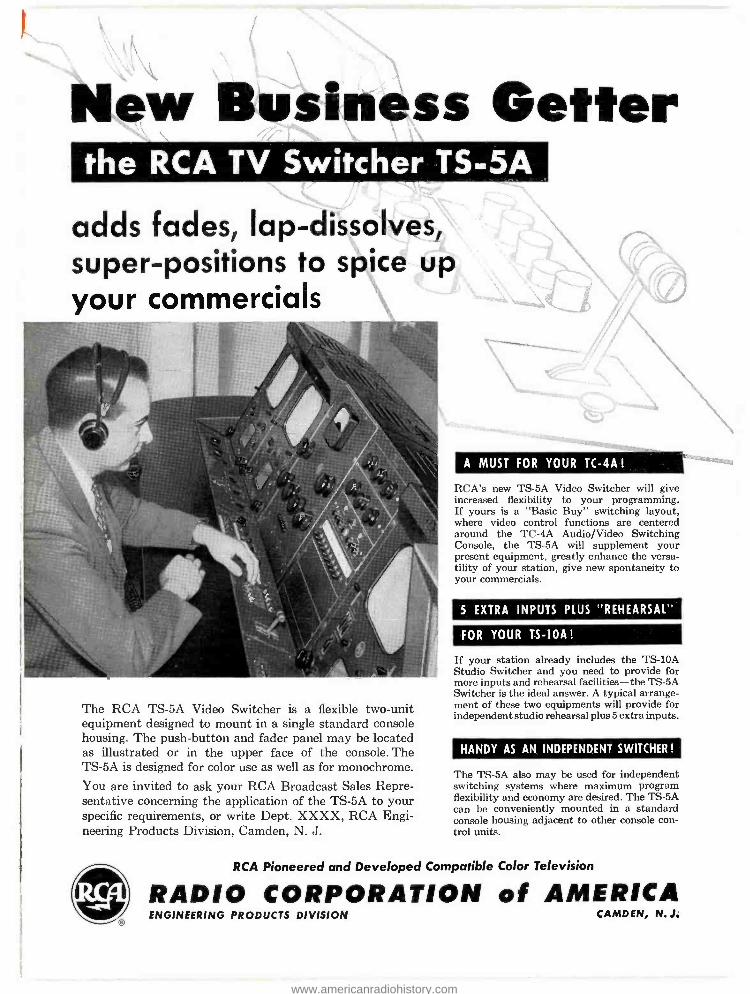
New Business Getter the RCA TV Switcher TS -5A
adds fades, lap -dissolves, super -positions to spice up your commercials
The RCA TS -5A Video Switcher is a flexible two -unit equipment designed to mount in a single standard console housing. The push -button and fader panel may be located as illustrated or in the upper face of the console. The TS -5A is designed for color use as well as for monochrome.
You are invited to ask your RCA Broadcast Sales Repre- sentative concerning the application of the TS -5A to your specific requirements, or write Dept. XXXX, RCA Engi- neering Products Division, Camden, N. J.
A MUST FOR YOUR TC -4A !
RCA's new TS -5A Video Switcher will give increased flexibility to your programming. If yours is a "Basic Buy" switching layout, where video control functions are centered around the TC -4A Audio /Video Switching Console, the TS -5A will supplement your present equipment, greatly enhance the versa- tility of your station, give new spontaneity to your commercials.
5 EXTRA INPUTS PLUS "REHEARSAL"
FOR YOUR TS -10A!
If your station already includes the TS-10A Studio Switcher and you need to provide for more inputs and rehearsal facilities -the TS -5A Switcher is the ideal answer. A typical arrange- ment of these two equipments will provide for independent studio rehearsal plus 5 extra inputs.
HANDY AS AN INDEPENDENT SWITCHER !
The TS -5A also may be used for independent switching systems where maximum program flexibility and economy are desired. The TS -5A can be conveniently mounted in a standard console housing adjacent to other console con- trol units.
RCA Pioneered and Developed Compatible Color Television
RADIO CORPORATION of AMERICA `_ ENGINEERING PRODUCTS DIVISION CAMDEN, N. J.
www.americanradiohistory.com

Now -far ahead of its time -Great new
IOKW Short Wave Transmitter! 32 new, special features that won't be matched for years - now available in new RCA BHF -IOA Broadcast Transmitter!
NOVO Cl 0 ® _ -
: 1.111 11111iiJ11 Ililli,n! .
1111111111 WInit!t
Front view of BHF -10A transmitter reveals handsome, functional des gn.
Requires only 33 sq. ft. of floor space.
Puts the BROADCASTER far ahead! The new BHF -10A has sufficient power to cover large service areas; quick frequency change, to increase use- fulness; unsurpassed reliability, for unbroken service. The opportunities for commercial stations to increase revenue are built inl
Puts the ENGINEER far ahead! Here are just a few advantages for the engineer: easy maintenance, through use of a limited number of high -gain tubes. Air cooling. Simplest tuning. Elec- tronically protected circuits - and full power for zonal broadcasting in 90, 75 and 60 metre bands, and international broadcasting over a frequency range of 3.2 - 26.1 mc.
These are just a few of 32 special features of this RCA transmitter that ushers in a new era of radio - proud achievement of RCA's 30 years of broadcast pioneering. Write today for booklet giving complete specifications!
RCA INTERNATIONAL DIVISION
Puts the INVESTOR far ahead! Years -ahead engineering makes the new RCA 10KW transmitter an exceptionally sound investment. Installation costs are low, for this self -contained transmitter can be installed in existing buildings with- out alteration. Maintenance has been simplified -and routine oper- ation can be handled by non -tech- nical personnel!
Rear view, power output section showing PA tuning and output coupling unit.
RADIO CORPORATION ofAMERICA RCA BUILDING 30 ROCKEFELLER PLAZA, NEW YORK, N.Y., U.S.A.
www.americanradiohistory.com
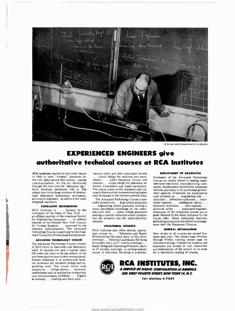
A lemure and demonstration in physics.
EXPERIENCED ENGINEERS give authoritative technical courses at RCA Institutes
RCA Institutes started its first small classes in 1909 to train "wireless" operators for the only radio service then known- marine communication. As the art developed through the years into the "electronic age," RCA Institutes developed with it. The school now trains large numbers of develop- ment laboratory technicians, servicemen, and station engineers -as well as a few radio telegraph operators.
SCHOLASTIC RECOGNITION
RCA Institutes is . . . licensed by the University of the State of New York .. .
an affiliate member of the American Society for Engineering Education ... an affiliate member of the Greater New York Council for Foreign Students ... approved by the Veterans Administration. The Advanced Technology Course is approved by the Engi- neers' Council for Professional Development.
ADVANCED TECHNOLOGY COURSE
The Advanced Technology Course consists of 2610 hours of classroom and laboratory work. It requires two and a quarter years (50 weeks per year) in the day school, or six and three quarter years in the evening school. Subject treatment is at professional level; the textbooks are standard college and en- gineering texts. This course covers such subjects as ... college physics ... advanced mathematics and its application to electrical and communication problems ... English in industry ... drafting and shop work .. .
vacuum tubes and their associated circuits . circuit design for receivers and trans-
mitters ... audio frequency circuits and practice ... circuit design for television re- ceivers, transmitters and studio equipment. The course omits purely academic and cul - tural subjects so that competent technologists may be trained in the shortest possible time.
The Advanced Technology Course is spe- cially attractive to ... high school graduates ... engineering school graduates wishing a more specialized knowledge of the radio - television field ... junior college graduates seeking a superior technical -school prepara- tion for entrance into the radio -television industry.
VOCATIONAL COURSES
RCA Institutes also offers shorter, special- ized courses in ... Television and Radio Broadcasting (I IA years, days; or 41 years, evenings) ... Television and Radio Servicing (9 months, days; or 27 months, evenings) ... Radio Telegraph Operating (9 months, days; or 27 months, evenings). A correspondence course in Television Servicing is available.
EMPLOYMENT OF GRADUATES
Graduates of the Advanced Technology Course are readily placed in leading radio - television- electronic manufacturing corn - panies, development laboratories, broadcast stations, and many U. S. and foreign govern- ment agencies. Graduates are employed in such positions as ... engineering aide . . .
instructor ... laboratory technician ... trans- mitter engineer ... intelligence officer . . .
electronic technician ... field engineer . . .
technical writer . . . announcer-engineer. Graduates of the vocational courses are in great demand in the fields indicated by the course titles. Many companies interview graduating students at the school by arrange- ment with the Placement Director.
GENERAL INFORMATION
New classes in all courses are started four times each year. Day classes meet Monday through Friday; evening classes meet on alternate evenings. Prospective students and employers are invited to visit classrooms and laboratories of the school, or to write for a descriptive catalog of courses.
RCA INSTITUTES, INC. A SERNCE OF RADIO CORPORATION of AMERICA
350 WEST FOURTH STREET NEW YORK 14, N.Y.
Tel: WAtkins 4 -7845
www.americanradiohistory.com

for "live"
pickup
;. RCA -6474/-14___ Image Orthicon -- You are looking at the new RCA television -- rarpera tube for simultaneous color pickup,- the camera tube-that has made compatible "live" color pickup a practical reality. - - -___.
The 6474/1854 has exceptional sensitivity - a Designed
response approaching that of the / /eye. Designed to operate ort a substantially linear signal- output curve, it is capable of pro- '"-- - ducing a color pictyra having natural tone values _ and-accurate derail. Furthermore, the 6474/1854 // features a signal] -ia-n se ratio and contrast range commensurate with the ëx'ärting -re, utrementtt of color reproduction. r- ---._ -------y
Like all RCA tubes for broadcast and/TV station ,operations, RCA -6474/1854 Image Orthicons are /available through your local RCA Tube Distributor.
Ask him about RCA's new Tube Jriventory Main- tenance Plan that enables him to function literally as a tube warehouse for yÖur s ion.
®
SEALED for your
protection Every RCA; 6474/ 1856 Image Orthi- con for replacement use is sealed in its own sturdy, tamper- proof container, The unbroken red seal is
your assurance that your tube is factory fresh.
C. ;
RCA Pioneered and Developed Compatible Color Television
RADIO CORPORA ON of AMERICA ELECTRON TUBES ARR/sON, N. J.
www.americanradiohistory.com
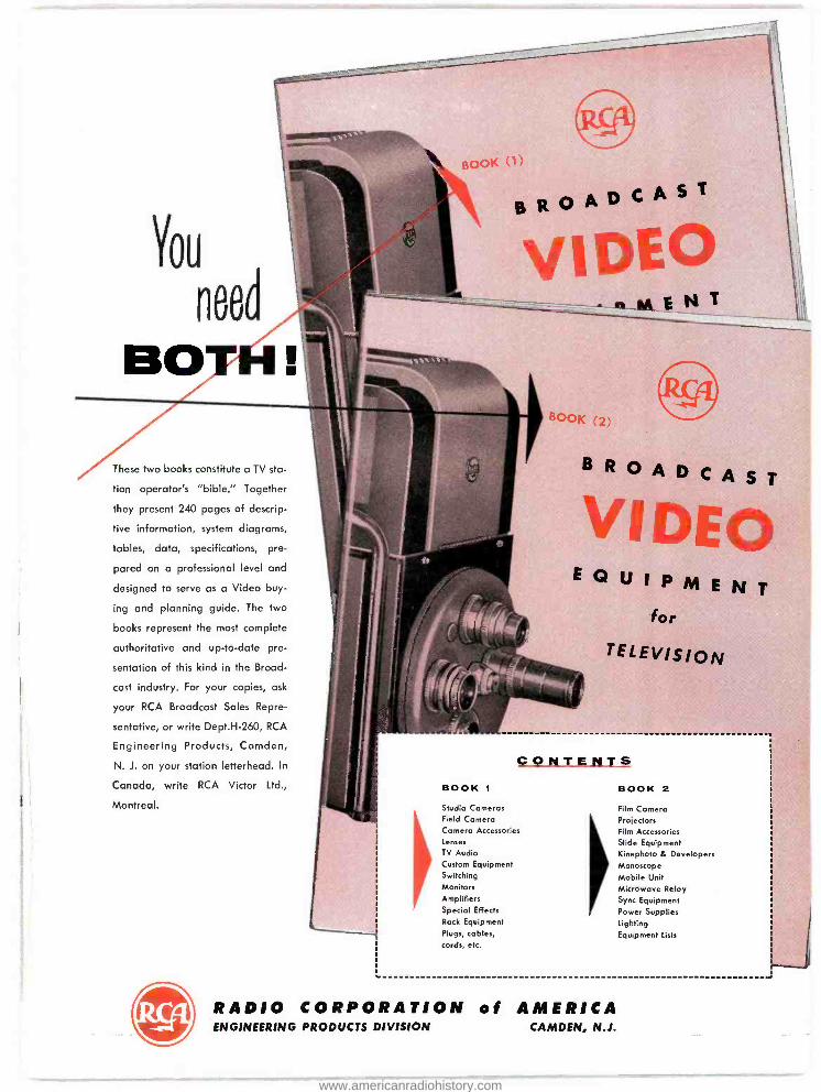
You
need
so
BOOK I
B R O A D C A S T
These two books constitute a TV sta-
tion operator's "bible." Together
they present 240 pages of descrip-
tive information, system diagrams,
tables, data, specifications, pre-
pared on a professional level and
designed to serve as a Video buy-
ing and planning guide. The two
books represent the most complete
authoritative and up -to -date pre-
sentation of this kind in the Broad-
cast industry. For your copies, ask
your RCA Broadcast Sales Repre-
sentative, or write Dept.H -260, RCA
Engineering Products, Camden,
N. J. on your station letterhead. In
Canada, write RCA Victor Ltd.,
Montreal.
- nMEN
B R O A D C A S T "i' aim moo
E Q U I P M E N T
for
TELEVISION
CONTENTS BOOK 1 BOOK 2
Studio Cameras Field Camera Camera Accessories Lenses
TV Audio Custom Equipment Switching Monitors Amplifiers Special Effects
Rock Equipment Plugs, cables, cords, etc.
Film Camera Projectors Film Accessories Slide Equipment Kinephoto & Developers Monoscope Mobile Unit Microwave Relay Sync Equipment Power Supplies Lighting Equipment Lists
RADIO CORPORATION of AMERICA ENGINEERING PRODUCTS DIVISION CAMDEN, N.J.
www.americanradiohistory.com

MOST HIGH-POWER TV STATI Over 100 RCA High -Power TV Transmitter
Equipments Already Delivered Not by towns -not by cities -not by states -but across the entire country as a whole -most high -power TV stations are using RCA equipment. Today, more than 70 are "on -air" and operating at the maximum power permitted by the FCC. Almost every week more Television stations are going to high power- with RCA equipment. U ea MING ,... .
110 -.11117-----
RC S SO-KW VHF TRANSMITTER
R High -Power transmitter -a d- ntenna combinations can liter. Ily
"Rood" TV service areas with strong sig- .y; nais -close in AND for out!
www.americanradiohistory.com
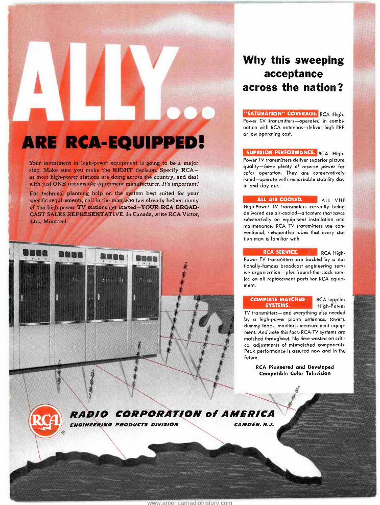
ARE RCA-EQUIPPED! Your investment in high -power equipment is going to be a major step. Make sure you make the RIGHT decision. Specify RCA - as most high -power stations are doing across the country, and deal with just ONE responsible equipment manufacturer. It's important!
For technical planning help on the system best suited for your specific requirements, call in the man who has already helped many of the high -power TV stations get started -YOUR RCA BROAD- CAST SALES REPRESENTATIVE. In Canada, write RCA Victor, Ltd., Montreal.
SOSO alga
jaf
RADIO CORPOR
Why this sweeping acceptance
across the nation?
"SATURATION" COVERAGE. RCA High - Power TV transmitters- operated in combi- nation with RCA antennas -deliver high ERP
at low operating cost.
SUPERIOR PERFORMANCE. RCA High - Power TV transmitters deliver superior picture quality -have plenty of reserve power for color operation. They are conservatively rated -operate with remarkable stability day in and day out.
ALL AIR -COOLED. ALL VHF High -Power TV transmitters currently being delivered are air -cooled -a feature that saves
substantially on equipment installation and maintenance. RCA TV transmitters use con- ventional, inexpensive tubes that every sta- tion man is familiar with.
RCA SERVICE. RCA High - Power TV transmitters are backed by a na-
tionally- famous broadcast engineering serv-
ice organization -plus 'round- the -clock serv-
ice on all replacement parts for RCA equip- ment.
COMPLETE MATCHED SYSTEMS.
RCA supplies High -Power
TV transmitters -and everything else needed by a high -power plant; antennas, towers, dummy loads, monitors, measurement equip- ment. And note this fact: RCA TV systems are matched throughout. No time wasted on criti- cal adjustments of mismatched components. Peak performance is assured now and in the future.
RCA Pioneered and Developed Compatible Color Television
ON of AMERICA ENGINEERING PRODUCTS DIVISION CAMDEN, N.J.
www.americanradiohistory.com

Plan for
MORE spots
MORE commercials MORE profits
features of RCA's BC -4A Easily expanded for dual -channel
broadcast use
Single BC -4A controls 9 inputs - four simultaneously
Paired BC -4A's double facilities - provide dual -channel operation
Entirely self -contained, completely wired unit -no separate desk
required
Program and audition facilities
Talkback or program cue to remote lines
Three preamplifiers -all amplifiers RCA Broadcast "plug -in" type
High degree of accessibility
2J8785
... with RCA's low -cost, high-efficiency broadcast
studio control console BC -4A
Designed originally to meet the need for economy in the smaller station, RCA's Audio Central BC-4A also fills an important place in medium and large stations.
For example -the BC -4A can carry the whole sta- tion during slack hours. It is useful as a low -cost, semi -permanent installation in remote locations, such as dance halls or fairs. It is adequate for a new studio, interview room, newsroom, etc. As an "add -a- unit" audio control, it permits "block - building" as needed.
A single BC -4A provides sufficient control and switching facilities for studio, announce booth, turntables, network, remotes and tape recorders. The addition of another BC -4A doubles these facili- ties and permits complete dual -channel operation.
Let your RCA Sales Representative tell you how the BC -4A can increase your facilities at low cost.
PIONEERS IN AM BROADCASTING FOR OVER 25 YEARS
RADIO CORPORATION of AMERICA ENG /NEER /NG PRODUCTS DIVISION CAMDEN, N.J.
www.americanradiohistory.com


