Calhoun: The NPS Institutional Archive Faculty and Researcher Publications Faculty and Researcher Publications Collection 1999 Compressible Dynamic Stall Control Using a Shape Adaptive Airfoil Chandrasekhara, M.S. M.S. Chandrasekhara, M.C. Wilder, and L.W. Carr, "Compressible Dynamic Stall Control Using a Shape Adaptive Airfoil", AIAA Paper 99-0650 Reno, NV, Jan. 1999 (Under Review for AIAA Journal). http://hdl.handle.net/10945/50034
Transcript
Calhoun: The NPS Institutional Archive
Faculty and Researcher Publications Faculty and Researcher Publications Collection
1999
Compressible Dynamic Stall Control Using a
Shape Adaptive Airfoil
Chandrasekhara, M.S.
M.S. Chandrasekhara, M.C. Wilder, and L.W. Carr, "Compressible Dynamic Stall
Control Using a Shape Adaptive Airfoil", AIAA Paper 99-0650 Reno, NV, Jan. 1999
(Under Review for AIAA Journal).
http://hdl.handle.net/10945/50034
. (c)l999 American Institute of Aeronautics & Astronautics
A994 6516 7
AIAA 99-0650 Compressible Dynamic Stall Control Using a Shaped Adaptive Airfoil MSChandrasekhara, Naval Postgraduate \ School , Monterey, CA; M.C.Wilder, MCAT, Inc., Mountain View, CA; . and L.W.Carr, AvRDEC, USArmy AMCOM NASA Ames Research Center Moffett Field, CA
37th AIAA Aerospace Sciences Meeting and Exhibit
January ii-14,1999 / Reno, NV
For permlsslon to copy or republish, contatt the American lnstltute of Aeronautics and Astronautics 1801 Alexander Bell Drlvs, Suits 500, Reaton, VA 20191
(c)l999 American Institute of Aeronautics & Astronautics
.
*
AIAA-99-0650
COMPRESSIBLE DYNAMIC STALL CONTROL USING A SHAPE ADAPTIVE AIRFOIL
M.S.Chandrasekhara’ Navy-NASA Joint Institute of Aeronautics, Dept. of Aeronautics and Astronautics
Naval Postgraduate School, Monterey, CA 93943 M.C.Wilder’
MCAT Inc., 625 Ellis St., Mountain View, CA 94035 and
L.W.Carr’ Aeroflightdynamics Directorate, AvRDEC, U.S. Army ATCOM and
Experimental Physics Branch, NASA Ames Research Center, Moffett Field, CA 94035
ABSTRACT Compressible dynamic stall control using a dynamically deforming leading edge airfoil is reported. The technique uses real-time leading edge shape adaptation to manipulate the local adverse pressure gradient over an oscillating airfoil. This produces attached leading edge flow at all angles of attack in the cycle. The shape change schedule is tailored to achieve the “right” airfoil shape through the dynamic stall regime by rounding the nose on the upstroke and sharpening it on the downstroke. The method exploits the favorable effects of shape adaptation on the potential flow to modify the pressure field and maintain the peak vorticity level below the critical level at which the dynamic stall vortex develops. The sensitivity of the flow to rate of nose curvature change and the angle of attack at which the initiation occurs has been investigated.
CP C ~rnl” C
f k M
ke s, n
t U,
Us V X,Y a
NOMENCLATURE pressure coefficient peak suction pressure coefficient airfoil chord frequency of oscillation, Hz reduced frequency = rr f c N, freestream Mach number static pressure Reynolds number based on chord coordinates along and normal to airfoil surface time freestream velocity tangential surface velocity suction or blowing velocity chordwise and vertical distance angle of attack
a, mean angle of attack V kinematic viscosity P density n spanwise component of vorticity al circular frequency
1. INTRODUCTION The problem of compressible dynamic stall is well known to both rotary wing and fixed wing aerodynamicists. Research completed’ thus far has shown that unsteady flow separation over an airfoil can be induced by many mechanisms. Inherent to the problem is the rapid acceleration of the fluid around the leading edge of the airfoil that results in a steep adverse pressure gradient downstream of the suction peak, and under certain conditions, supersonic flow leading to shocks and shock-induced separation. When dynamic stall occurs, the vorticity coalesces rapidly and it is abruptly shed in a tightly wound vortex, instead of being diffused gradually through the boundary layer. This suggests that the management of unsteady vorticity may be an effective flow control technique.
Vorticity management in two-dimensional flow can be accomplished if the adverse surface pressure gradient over the airfoil can be manipulated in accordance with the vorticity flux equation (Ref. 2).
a.2 au, V-E- +1*+vn al at P as
Most research on stall alleviation and flow separation control uses suction/ injection of fluid or acoustic excitation to energize the airfoil boundary layer”J. It is now well known that the injection rates and the acoustic power required increase steeply with increasing free stream Mach number. This makes flow control
- Research Professor and Associate Director, Mailing Address: NASA Ames Research Center, M.S. 260-1, Moffett Field, CA 9403% 1000, Assoc. Fellow, AIAA ’ Senior Research Scientist, Member AIAA ’ Research Scientist & Group Leader, Member AIAA 0 This paper is declared a work of the U.S. Government and is not subject to copyright protection in the United States.
American Institute of Aeronautics and Astronautics
Dow
nloa
ded
by N
AV
AL
PO
STG
RA
DU
AT
E S
CH
OO
L o
n Se
ptem
ber
30, 2
016
| http
://ar
c.ai
aa.o
rg |
DO
I: 1
0.25
14/6
.199
9-65
0
(c)l999 American Institute of Aeronautics & Astronautics
extremely difficult under flight conditions, although recent studies reported in Ref.5 indicate progress in this regard.
The interdependence between the surface acceleration, pressure gradient and vorticity flux (for V = 0) seen in the vorticity flux equation can be exploited to develop another approach to flow control. It involves real-time airfoil shape adaptation. The surface acceleration term is about two orders of magnitude smaller than the pressure gradient term and its contribution to balancing the equation can be ignored. But, it is well known that airfoil geometry change induces a large effect on the external potential flow, and hence, on the pressure field. Consequently, airfoil geometry modification provides an effective control mechanism for vorticity management. Dynamically changing the leading edge curvature of a pitching airfoil causes rapid changes in the potential flow pressure distribution over it. Carefully tailoring the rate of curvature provides the ability to manipulate the unsteady vorticity in real-time. This can lead to avoidance, or at least delay, of flow separation. From a fundamental point of view, the airfoil unsteadiness and the surface acceleration arising from shape adaptation are two independent time scales which interact strongly to produce the measured effects, which manifest themselves through changes in the outer potential flow.
It was shown in earlier work on the subject (Ref. 6) that changing the leading edge curvature of an NACA 0012 airfoil can provide significant stall delay (about 5 deg at M = 0.3). That study also identified certain intermediate shapes that were dynamic stall vortex free. The extreme sensitivity of the airfoil peak suction pressure to the flow acceleration around the airfoil leading edge resulted in reduced peak suction levels when the nose radius was increased. This approach distributed the low pressure region over a wider extent on the airfoil upper surface and hence, reduced the leading edge adverse pressure gradient. Thus, it became possible to reach higher angles of attack before stall was encountered and satisfactory airfoil performance ensued over a larger operating envelope. This flow control method is very valuable for compressible dynamic stall control, which is always a leading edge type of stall, dominated by a strong clockwise vortex convecting over the airfoil. The redistribution of the vorticity flux arising from nose radius changes can be tailored to eliminate the dynamic stall vortex completely and to vastly improve airfoil force and moment loops. ~
Although Ref. 6 demonstrated control of compressible dynamic stall using fixed, round nosed airfoils, rotor applications require dynamic airfoil shape adaptation because of the large differences in flow speeds on the advancing and retreating sides. The fluid mechanics of
AIAA-99-0650
the flow over airfoils of different shapes also needs to be established since it plays a major role in the problem. In particular, determining the shapes that the airfoil can take without stalling during such a maneuver is critical. The present experiments were focused on controlling the flow over a sinusoidally oscillating airfoil by determining the dynamic shape variations that produced the most attached flow over the range of angles of attack of interest. A “sharp-to-round” shape change profile was chosen to maintain the airfoil shapes within the range that produced attached flow as established in Ref. 6. Flow control was achieved by constructively utilizing shape adaptation to effectively distribute the vorticity over a dynamically deforming leading edge (DDLE) airfoil.
2. DESCRIPTION OF THE EXPERIMENT A. The DDLE Airfoil
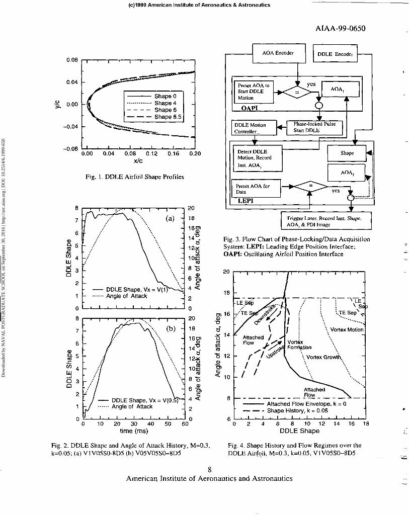
Practical implementation of real-time adaptation of an oscillating airfoil requires overcoming the demanding challenges of design and fabrication. The DDLE airfoil is a 15.24cm chord, NACA 0012 derivative airfoil, specially developed for the present purpose (Ref. 7) offers a solution to this challenge. Its leading 20% is a thin skin, cast from a carbon-fiber composite; the rest is machined from solid metal. The skin is about 50pm thick at the leading edge and it is attached with a tang to a mandrel, shaped to the NACA 0012 profile, housed between the airfoil upper and lower surfaces. The mandrel is connected to a computer controlled, brushless servomotor drive system. It translates in the chordwise direction by less than 2mm to produce up to 320% continuoX change in the airfoil leading edge radius. The displacement required is much smaller (typically less than Imm) for most applications. An integer change in shape number is produced by a 75 l.trn displacement. Shape-O corresponds to the NACA 0012 profile. Fig. 1 shows some of the shapes that can be generated with this design. The mechanism is designed to work synchronously with the airfoil oscillating at a frequency of up to 20Hz in the compressible dynamic stall facility (CDSF). The airfoil is held between the CDSF test section walls with glass inserts providing optical access to the region -0.15 I x/c 5 0.35. More details about the DDLE can be found in Ref. 7.
B. The Deformation Schedule A typical deformation schedule consists of rounding the nose by retracting the leading edge, holding the final shape for a dwell period and extending the leading edge back to the original shape. Different rates were~ used for the pull-back and push-forward motions, and the dwell period. The leading edge deformation rate is linearly proportional to the speed of rotation of the servomotors. This is referred to as V(m) (see Ref. 6), where nz is the motor speed in rev/set. When the airfoil is held at different shapes such that steady flow is attained, the
2 American Institute of Aeronautics and Astronautics
Dow
nloa
ded
by N
AV
AL
PO
STG
RA
DU
AT
E S
CH
OO
L o
n Se
ptem
ber
30, 2
016
| http
://ar
c.ai
aa.o
rg |
DO
I: 1
0.25
14/6
.199
9-65
0
(c)l999 American Institute of Aeronautics & Astronautics
deformation rate is referred to as V(0). The retraction stroke consists of pulling the fully extended NACA 0012 (shape-O) leading edge to the final shape-z (generally shape-8.5) at rate V(x)=Vx. This shape is held for a duration Dt ms. The leading edge is then pushed forward to the NACA 0012 shape at rate V(y)=Vy. Using these parameters, the deformation schedule is indicated by VxVySO-zDt. The actual shapes attained are determined using an encoder on the drive motor. The encoder is read using a p-VAX II computer. Two shape-change schedules, listed in Table I, were used. Schedule VlVO%O-8D5 corresponds to the faster deformation motion with Vx=Vl, Vy=VO.S, SO-z=SO-8 and Dt=5 ms. Schedule V05V05SO-8D5 represents the slower motion with Vx=VO.S, Vy=VO.S, SO-z=SO-8 and Dt=Sms.
Table I. Deformation Schedules
Deformation V(x) V(Y) Start End Hold Schedule = = Shape Shape Time
vx vy ms v 1 vo5so- VI vo5 0 8.5 5 8D5 vo5vo5so- vo5 vo5 0 8.5 5
1 8D5
The actual shape variations achieved are shown in Fig. 2 along with the corresponding angle of attack variations for both these schedules. It can be seen from the figure that a satisfactory control system response includes mild transients while the system settles down. These manifest as small changes in shape. The oscillations were minimized during the system tuning process for each condition such that the DDLE airfoil shape could be maintained to within a half-integer shape at the final round shape during deformation.
The flow being studied is affected by several parameters. The rate of nose curvature change, the angles of attack of initiation and completion of the deformation, the dwell duration at a particular shape, the shape adaptation profile, the airfoil reduced frequency, and freestream Mach number. A detailed and systematic study of the effects of varying these quantities is also required. Changing any of the motion parameters involves re-tuning the control system, which requires systematic manipulation of the feedback system gains and damping parameters. In order to determine those that have the most influence, exploratory studies were conducted. In particular, the effect of dynamic deformation rate on the attached flow envelope was determined for different rates. The effect of V(m) on the attached flow envelope for V(O), V(1) and V(l0) has been discussed in Ref. 6. By oscillating fixed DDLE shape airfoils at the same flow conditions, the geometries that were nearly dynamic stall vortex
AIAA-99-0650
free were also identified. The oscillating airfoil shape change schedule that offered the most potential for success was determined based on these data.
C. Experimental Technique and Conditions The Point Diffraction Interferometry (PDI) technique was used to record flow images at specific angles of attack as the DDLE airfoil was dynamically deformed while oscillating at a=lO”+lO”sinot, at M = 0.3 and k= 0.05. The instantaneous DDLE position (shape) encoder values were recorded for each image. Two independent time scales, namely, the airfoil reduced frequency and the dynamic shape change rate, are present in this flow. To obtain properly phase-locked interferograms in the study, custom electronic hardware was needed, which was developed in-house. Fig. 3 presents the schematic of the approach used.
The angle of attack of initiating the DDLE motion was set on the Oscillating Airfoil Position Interface (OAPI). When a match occurred between the selected value and the instantaneous angle of attack encoder (attached to the oscillation drive system) value, a command pulse was issued to the DDLE controller. The controller responded with a variable delay to this external trigger pulse initiating the airfoil shape change. The delay was dependent upon the step of control logic being executed at that instant of time. The actual angle of attack at which the airfoil deformation began was recorded on the Leading Edge Position Interface (LEPI) using the I-IL-high pulse generated from the 41h bit of the DDLE encoder. The 41h bit was selected to prevent noise from accidentally triggering the leading edge retraction. The LEPI subsequently issued a pulse to trigger the laser at any desired shape (selected on its front panel). With this equipment, interferograms could be acquired at any desired angle of attack and/or shape number (airfoil leading edge curvature value). The data being reported were acquired only when the airfoil angle of attack at the instant of the DDLE movement remained within the predetermined tolerance of f 0.25 deg. The PDI images were initially evaluated qualitatively. Quantitative analysis was conducted by processing them on an IRIS Workstation using software developed at the Fluid Mechanics Laboratory and, the pressures were recovered from the fringes using isentropic flow assumptions.
D. Uncertainty Estimates The estimated uncertainties in the data are as follows: Mach number: f 0.005 angle of attack: 0.05 deg reduced frequency: 0.005 airfoil shape: 0.05 airfoil displacement: 4vm cp : +O.l atM=0.3
American Institute of Aeronautics and Astronautics
Dow
nloa
ded
by N
AV
AL
PO
STG
RA
DU
AT
E S
CH
OO
L o
n Se
ptem
ber
30, 2
016
| http
://ar
c.ai
aa.o
rg |
DO
I: 1
0.25
14/6
.199
9-65
0
(c)l999 American Institute of Aeronautics & Astronautics
cp : mm
-0.5 at M = 0.3;
-0.35 at M = 0.45 dCp/d(x/c): f 25 change in a during DDLE movement: 310.25
The reader is referred to ~Ref. 6 for a explanation of the way these were determined.
3. RESULTS AND DISCUSSION
detailed
The results for flow over various fixed shape DDLE airfoils have been described in Ref. 6 for both steady and unsteady flows. In the following, these are compared with the case of the Shape Adapting while Pitching (SAP) airfoil to identify the relevant fluid physics issues.
Ref. 6 shows that increasing the leading edge radius of curvature produces attached flow over an airfoil at angles of attack considerably higher than the static stall angle of I4 deg of the baseline NACA 0012 airfoil. In fact, at M = 0.3, the flow was still attached at I8 deg over the shape 8 airfoil in steady flow. Furthermore, the separated flow over the NACA 0012 airfoil at I8 deg could be made to reattach by simply adapting to shape 4. for example.
Real-time airfoil adaptation involves a deformation rate. Hence, dynamic deformation studies were also conducted with the airfoil held at fixed angles of attack (Ref. 6), which showed that the deformation rate should be kept low to reduce the tendency of the flow vorticity to coalesce. An example of the resulting flow development is shown in Fig. 4 along with the airfoil shape schedule for the SAP case of VlV05SO-8D5. Primarily the attached flow envelope shrank slightly at the deformation rate V(l) from that obtained at V(O), but the major difference is the effect on the vorticity dynamics. A vortex similar to the dynamic stall vortex was produced for rounder shapes (shape number > 8.5) starting at very low angles of attack (a = 9 deg), whose subsequent evolution was similar to that observed in the dynamic stall flow situation.
Ref. 6 has also documented that the DDLE shape-g.5 airfoil flow was dynamic stall vortex free at M = 0.3 and k = 0.05 when oscillated at a=10”+10”sinot. This result and the fact that the unsteady flow pressure field development lags that of steady flow (by l-2 deg. depending upon k, Ref. 8) together help define the airfoil shapes that need to be reached and maintained during real-time shape adaptation for successful flow control. It will be shown below that the success attained depends upon the path of shape change followed in this window of attached flow shown in Fig. 4. It can be seen here that trailing-edge flow reversal first occurs
AIAA-99-0650
when the leading edge is dynamically deformed from shape-0 to shape-8 for a = 14-16 deg. Full flow separation develops only when this flow reversal reaches the leading edge, even at high angles of attack. This is unlike the NACA 0012 airfoil flow where leading-edge stall develops abruptly. It is possible to maintain attached leading edge flow without the dynamic stall-like vortex even when the flow reversal reaches the leading edge for shapes O-8, even at high angles of attack, whereas a dynamic stall vortex is present from very low angles for the rounder shapes.
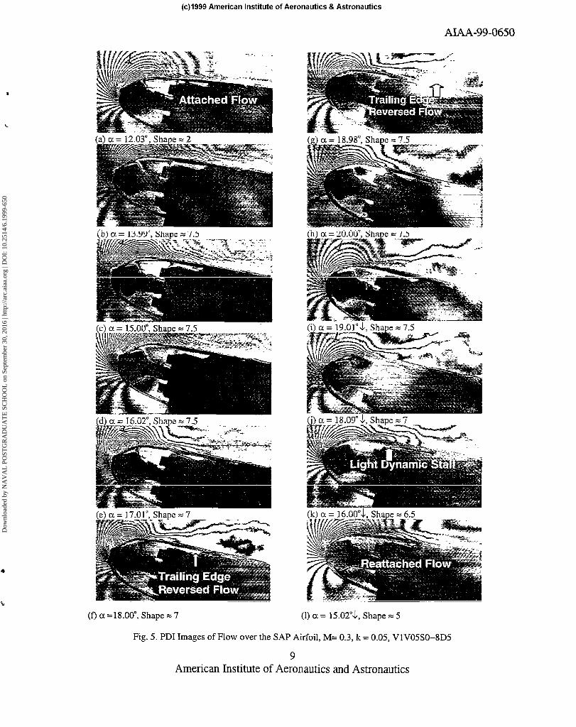
A. Qualitative Description of the SAP Airfoil Flow Figure 5 presents 12 interferograms recorded at different angles of attack for the SAP case at M = 0.3, k = 0.05 with shape schedule VIV05SO-8D5. It is clear from the fringe pattern in Fig. 5a that the flow is fully attached at a = 12.03 deg, for shape 2. Attached flow is also seen in Figs 5b and 5c for a = I4 deg and 15 dcg respectively, for shape-7.5, although some disturbance is noticeable in Fig. 5c near x/c = 0. I. Results presented in Ref. 6 show that the flow over the fixed shape-g.5 airfoil generally behaves similarly to that seen in Fig. 5. It is worth mentioning here that for the NACA 0012 airfoil, dynamic stall onset occurs at a = 14 deg at M = 0.3. The flow appears fully attached at a = 16 deg in Fig. 5d. Traces of trailing edge separation can be seen in Fig. 5e for a = 17 deg over the shape-7 airfoil, which become more pronounced for a = 18 deg (Fig. 5f) and for a = 19 deg (Fig. 5g). A close look at the leading edge flow shows the presence of a large number of fringes, indicating that a strong leading edge suction is being produced even when the trailing edge separation has progressed up the airfoil to x/c = 0. I. At a = 20 deg, Fig. Sh, the maximum number of fringes has decreased and hence, the peak suction pressure has dropped from that observed in Fig. 5g, but the leading edge flow is still attached. During the downstroke, the flow at a = I9 deg (Fig. 5i) and a = 18 deg (Fig. 5j) appears similar to that seen on the upstroke at these angles, with the only difference being that the maximum number of leading edge fringes is less on the downstroke. As the return to the sharp-nosed airfoil begins, light dynamic stall is induced at a = 16 deg, (Fig. 5k) in much the same way as was seen for the fixed shape-g.5 airfoil (Ref. 6). This is because the flow has to adjust to the more favorable decreasing angle of attack conditions, which is reflected in the flow field characteristics. Most interestingly, fully reattached flow develops at the high angle of attack of 15 deg on the downstroke for the shape-5 airfoil, and the suction peak gets well established again. In contrast, at this angle of attack, light dynamic stall was present in the flow over the~shape-8.5 airfoil in Ref. 6 leading to the conclusion that the SAP airfoil case is better than a
4 American Institute of Aeronautics and Astronautics
Dow
nloa
ded
by N
AV
AL
PO
STG
RA
DU
AT
E S
CH
OO
L o
n Se
ptem
ber
30, 2
016
| http
://ar
c.ai
aa.o
rg |
DO
I: 1
0.25
14/6
.199
9-65
0
(c)l999 American Institute of Aeronautics & Astronautics
fixed DDLE shape-85 airfoil. Fig. 5 shows that it is possible to manipulate the flow field in order to keep the leading edge flow attached throughout the entire oscillation cycle. Similar results were obtained for deformation schedule VOW05SO-8D5.
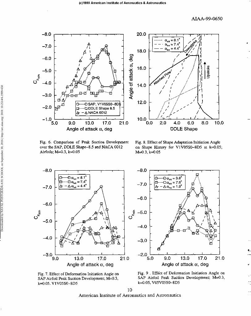
B. Peak Suction Development In Fig. 6, the development of the airfoil peak suction pressure coefficient Cpm,. , is compared for the NACA
0012, DDLE shape-g.5 and SAP airfoil geometries. The NACA 0012 airfoil generates the highest value of Crm,,(= -7.5), which indicates that the flow has become locally supersonic, however, no shocks are seen. In both the DDLE case and the SAP case, Cp,,“just reaches
the critical value with the DDLE shape-g.5 airfoil showing a more gradual fall of peak suction pressure. On the upstroke, the values for the SAP airfoil are slightly higher, suggesting that the suction lift over it tends to be marginally higher. Of greater interest is the 30% smaller size of the peak suction pressure loop for the SAP case. This difference between the DDLE shape-g.5 and SAP airfoil cases in both the upstroke and downstroke peak suction pressures is due to the different-extent of trailing edge separation present over the airfoils since there was no dynamic stall vortex in both flows. Because the flow reattaches at a = 15 deg for the SAP case as opposed to at a = 12 deg for the DDLE shape-g.5 case, its loop is smaller. In contrast, for the NACA 0012 airfoil, the shedding of the large dynamic stall vortex causes the flow to separate completely. Complete reattachment does not occur until a = 8 deg on the downstroke (Ref. 9) which results in a very large hysteresis loop in the moment coefficient as well. If shape adaptation were ideal and complete, a large difference in the Cl’,,” development between the upstroke and downstroke will not be present because the flow vorticity will be diffused through the boundary layer at a rate consistent with its production throughout the oscillation cycle. In reality, however, one can only expect to minimize the loop so that the airfoil can deliver a performance that is free from large separation effects. The results presented here suggest that satisfactory shape adaptation has been achieved for this experimental condition of M = 0.3 and k = 0.05 using the deformation schedule V IV05SO-8D5.
C. Effect of Deformation Initiation Angle of Attack on Peak Suction Development
Figure 7 shows the problems associated with initiating shape adaptation at different angles of attack. In this, the peak suction values for nominal start angles of attack of 4.4, 7.4 and 8.1 deg are compared. The corresponding airfoil shape variations through the oscillation cycle are shown in Fig. 8. It is clear from Fig. 7 that even a small difference of about 0.7 degrees
AIAA-99-0650
in the deformation initiation angle has a dramatic influence on the flow. The PDI pictures (not presented) show that a dynamic stall vortex develops for the cases when the airfoil deformation is initiated at the two lower angles. The vortex originates in both these cases at a = 12”which is lower than the dynamic stall onset angle of a = 14” for the NACA 0012 airfoil. But, it is shed at around I6 deg like that observed for the NACA 0012 airfoil at M=0.3 and k=0.05. But, the maximum suction developed does not compare well with that seen for the NACA 0012 shape. The major difference between the latter and these two cases of light dynamic stall over the shape adaptive airfoil is the much smaller Crmlnloop obtained in the adaptive airfoil flow. A study of Fig. 7 shows that the peak suction pressure loop for the successful case of shape adaptation is larger relative to that for the light dynamic stall cases. However, it is still better because the leading edge flow over the airfoil stays attached throughout the cycle and no dynamic stall vortex develops. Consequently, the pitching moment variation will be significantly smaller.
Although identical deformation schedules were used in the experiment, the large difference in aerodynamic loads at the angle of attack of airfoil deformation results in dramatically different shape change distributions over the oscillation cycle as can be seen in Fig. 8. The actual shape changes obtained are shown in it along with the attached flow envelope of Fig. 4. Initiating shape change from a = 4.4” causes rounder shapes by a < IO”, which are known to be inappropriate for maintaining attached flow. Shape number 8 is reached by a = I I”, which is in the vortex flow regime. Further, this shape is maintained for most part of the upstroke and some of downstroke. A similar effect is seen for a - 7.4”. Depending upon the shapes attained at ,“I, - different angles, the instantaneous potential flow over the airfoil is different and hence also, the pressure distributions. Thus, dramatically different flow behavior results.
Figure 9 shows the changes in the peak suction development compared for different motion initiation angles while adapting at V05V05SO-8D5. In this, deformation initiation angles, a,ni, = 1.9, 3.8, and 7.8 degrees are considered. The slower rate of deformation requires the adaptation to begin at a lower angle of attack so that the “right” airfoil shapes have been reached while pitching through the dynamic stall angles. For this slower rate of adaptation, the best results are obtained for aInIL = 3.8 deg, unlike the previous case of 8 deg. Furthermore, for a ,“,, = 7.8’, a larger peak suction pressure coefficient of about -7.8 develops in the oscillation cycle indicating that the local flow is strongly supersonic. The interferograms (not
5 American Institute of Aeronautics and Astronautics
Dow
nloa
ded
by N
AV
AL
PO
STG
RA
DU
AT
E S
CH
OO
L o
n Se
ptem
ber
30, 2
016
| http
://ar
c.ai
aa.o
rg |
DO
I: 1
0.25
14/6
.199
9-65
0
. (c)l999 American Institute of Aeronautics & Astronautics
AIAA-99-0650
presented here) show shocks present in the flow induce separation and then a dynamic stall, which causes the steep loss of the peak suction pressure seen in the figure. A light dynamic stall vortex was also observed for the case when the deformation was initiated at I.9 deg. The results presented in Fig. 7-9 demonstrate that the flow over an airfoil with the wrong shape resulting from improper shape adaptation can indeed separate prematurely, defeating the purpose of the effort. The extreme sensitivity of the flow to this aspect needs to be carefully considered in designing a good flow control system.
D. Effect of Deformation Rate on Flow Development
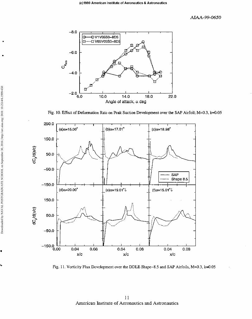
The effect of deformation rate on peak suction is compared in Fig. IO for the two “successful” cases VI V05SO-8D5 and VOW05SO-8D5, discussed above. Although the deformation begins at considerably different angles of attack (a = 3.8 and 8 deg) for these two cases, it is extremely interesting to note that on the upstroke, there is no noticeable difference in the peak suction pressure, until almost the top of the cycle. The suction peak also drops at the same rate for both cases. However, slight differences tippear in the peak suction values during the return to the NACA 0012 airfoil profile, with the loop for the slower rate deformation schedule V05V05SO-8D5 slightly smaller which makes it a preferred schedule. This is consistent with the conclusion presented in Ref. 6, where the slowest rate of geometry change was found to yield the best results in steady flow.
E. Vorticity Flux Distributions The vorticity fluxes calculated from the PDI derived pressure distributions by neglecting the unsteady terms for the shape-g.5 and the SAP airfoils are compared in Fig. 1 I. The large changes in the potential flow due to large real-time geometry modifications translate to a large effect on the pressure distribution, which should be seen on the vorticity flux also. It is clear from the figure that at a = 15 deg, the flux over the SAP airfoil for case VlV05SO-8D5 is generally lower than that over the DDLE shape-g.5 airfoil. The location of the peak vorticity flux value over the SAP airfoil moves toward the trailing edge at x/c = 0.08 in Fig. 1 la. No comparisons have been made with the distributions for the NACA 0012 airfoil since dynamic stall occurs at a = 14 deg and the flow separates completely by a = 16 deg. However, Ref. 6 showed that the vorticity flux distributions over the shape-g.5 airfoil were significantly superior to that over the NACA 0012 airfoil at the lower angles of attack, because of its lower maximum value and downstream.
Figure I I establishes that the SAP airfoil flow is generally better than that of the DDLE shape-g.5 airfoil on the upstroke. The peak vorticity flux for the SAP airfoil moves slightly upstream with increasing angle of attack (from x/c = 0.08 to x/c = 0.05, Fig. I lb-d), but it is lower than that for the shape-g.5 airfoil. The large peak of 225 seen for the DDLE shape-g.5 airfoil close to the leading edge in Fig. I lb is not observed for the SAP airfoil, even though its instantaneous shape of 7.5 attained dynamically is very close to the fixed DDLE shape-8.5. This can be attributed to the extreme sensitivity of the flow to the dynamic change of leading edge curvature. At a = 20 deg, Fig. I Id, the peak vorticity in the SAP airfoil flow drops to about 50% of that seen in the DDLE shape-8.5 airfoil flow, occurring at x/c = 0.05. In this, the peak vorticity occurs away from the leading edge and is significantly lower, when compared to the NACA 0012 airfoil prior to the onset of dynamic stall. This explains why no dynamic stall vortex was observed in the deforming airfoil flow. On the downstroke at a = 19 deg, Fig. 1 le, the SAP airfoil flow vorticity level is somewhat higher and leads the shape-g.5 airfoil, a trend that can be traced to the fact that the peak suction pressure is higher during the downstroke for the SAP airfoil. In Fig. I If, the values for the DDLE shape-g.5 airfoil are compared at a = 15.5 deg with the SAP airfoil at a = 15 deg. The higher vorticity flux levels suggest that a somewhat improved performance can be expected from the SAP airfoil.
4. CONCLUDING REMARKS Success in controlling compressible dynamic stall using a dynamically shape adaptive airfoil (as determined by the peak suction pressure development, vorticity flux and deformation schedule) has been reported. The flow has been shown to be dynamic stall vortex free for M = 0.3, k = 0.05 and a = IO” + 10” sin ot. The range of shapes O-8 was-found to offer the most potential for successful flow control. The leading edge was adapted in real-time within this window, by dynamic deformation, to introduce large changes (= 150%) in the airfoil nose curvature. This resulted in broader pressure distributions with lower peak suction values and led to a redistribution of the unsteady flow vorticity. The vorticity levels decreased to values where the dynamic stall vortex did not form. The deformation of the airfoil while pitching provided a slightly improved performance when compared to DDLE fixed shape-g.5 airfoil oscillating at the same conditions. The peak suction variation loop over the oscillation cycle for the adapting airfoil was found to be the smallest. The deformation rzitz, the initiation angle of attack and the amount of nose curvature change affect the success of the approach significantly with the slowest rate producing thernost benefit. More tests are needed to address the additional flow issues that arise at higher
-
I
6 American Institute of Aeronautics and Astronautics
Dow
nloa
ded
by N
AV
AL
PO
STG
RA
DU
AT
E S
CH
OO
L o
n Se
ptem
ber
30, 2
016
| http
://ar
c.ai
aa.o
rg |
DO
I: 1
0.25
14/6
.199
9-65
0
(c)l999 American Institute of Aeronautics & Astronautics
AIAA-99-0650
Mach numbers and other reduced frequencies over a ‘) Ahmed, S., and range of deformation schedule parameters.
Chandrasekhara, M.S., “Reattachment Studies of an Oscillating Airfoil
This work was supported by a research grant 5, May 1994, pp. 1006 - 1012.
(MIPRSBNPSAR007) from the U.S. Army Research Office and was monitored by T. L. Doligalski. The support of S. S. Davis, Fluid Mechanics Laboratory of NASA Ames Research Center, the assistance of R. A. Miller in model installation, and control system design effort of D.D.Squires and M.Khov, Sverdrup Technology, Inc. are gratefully acknowledged.
5. REFERENCES
’ Chandrasekhara, M. S., Wilder, M. C., and Can-, L. W., “Competing Mechanisms of Compressible Dynamic Stall”, AMA Journal, Vol. 36, No. 4, April 1998, pp. 387-393.
’ Reynolds, W. C., and Cat-r, L. W., “Review of Unsteady, Driven, Separated Flows”, AIAA Paper 85- 0527, Mar. 1985.
3 Alrefai, M., and Acharya, M., “Controlled Leading- Edge Suction for the Management of Unsteady Separation over Pitching Airfoils”, AIAA Paper 95- 2188, Jun. 1995.
4 Ahuja, K. K., and Burrin, R. H., “Control of Flow Separation” AIAA Paper 84-2298, Oct. 1984.
5 Seifert, A., Bahcar, T., Koss, D., Shepshelovich, M., and Wygnanski, I., “Oscillatory Blowing: A Tool to Delay Boundary Layer Separation” AlAA Journal, Vol. 3 I, No. IO, Oct. 1993, pp. 2052-2060.
’ Chandrasekhara, M. S., Wilder, M. C., and Cat-r, L. W., “Unsteady Stall Control Using Dynamically Deforming Airfoils”, AMA Journal Vol. 36, No. 10, Oct. 1998, pp. 1792-200.
’ Chandrasekhara, M. S., Cat-r, L. W., Wilder, M. C., Sticht, C. D., and Paulson, G. N., “Design and Development of a Dynamically Deforming Leading Edge Airfoil for Unsteady Flow Control”, ICIASF’97 RECORD, IEEE Publication 97CH36/21, Sep. 1997, pp. 132-140.
” Chandrasekhara, M.S., Cat-r, L.W., and Wilder, M.C., “Interferometric Investigations of Compressible Dynamic Stall Over a Transiently Pitching Airfoil”, AIAA Journal, Vol. 32, No. 3, Mar. 1994, pp. 586-593.
7 American Institute of Aeronautics and Astronautics
Dow
nloa
ded
by N
AV
AL
PO
STG
RA
DU
AT
E S
CH
OO
L o
n Se
ptem
ber
30, 2
016
| http
://ar
c.ai
aa.o
rg |
DO
I: 1
0.25
14/6
.199
9-65
0
(c)l999 American Institute of Aeronautics & Astronautics
Fig. 3. Flow Chart of Phase-Locking/Data Acquisition System: LEPI: Leading Edge Position Interface; OAPI: Oscillating Airfoil Position Interface
45
t5 uJ4
$3 8’5 2o I”““‘I”“““’
2
1 18
- ------ Angle of Attack
o-o UJ 16
% 20
18
16:
14;
12%
10;
6$,
42 8 - Attached Flow Envelope, k = 0 - - - Shape History, k = 0.05 2
n
.
61”“““““““‘J 0 2 4 6 8 10 12 14 16 18
DDLE Shape
I I I I I I I I I I
0 10 20 30 40 50 60-
time (ms) L
Fig. 2. DDLE Shape and Angle of Attack History, M=0.3, Fig. 4. Shape History and Flow Regimes over the k=0.05; (a) V 1 VOSSO-8D5 (b) VOW05SO-8D5 DDLE Airfoil, M=0.3, k=0.05, V IV05SO-8D5
--
-
8 American Institute of Aeronautics and Astronautics
Dow
nloa
ded
by N
AV
AL
PO
STG
RA
DU
AT
E S
CH
OO
L o
n Se
ptem
ber
30, 2
016
| http
://ar
c.ai
aa.o
rg |
DO
I: 1
0.25
14/6
.199
9-65
0
(c)l999 American Institute of Aeronautics & Astronautics
AW-99-0650
[Y = 19.01”&. Shane z 7.5
(f) a =18.00”, Shape = 7 (1) a = 15.02”&, Shape = 5
Fig. 5. PDI Images of Flow over the SAP Airfoil, M= 0.3, k = 0.05, VlV05SO-8D5
9 American Institute of Aeronautics and Astronautics
Dow
nloa
ded
by N
AV
AL
PO
STG
RA
DU
AT
E S
CH
OO
L o
n Se
ptem
ber
30, 2
016
| http
://ar
c.ai
aa.o
rg |
DO
I: 1
0.25
14/6
.199
9-65
0
(c)l999 American Institute of Aeronautics & Astronautics
AIAA-99-0650
-8.0
-7.0
-6.0
-5.0 j
0 -4.0
-3.0
-2.0
I I I I I
I I I ,
-1 .o 5.0 9.0 13.0 17.0 21 .o
Angle of attack a, deg
Fig. 6. Comparison of Peak Suction Development over the SAP, DDLE Shape-S.5 and NACA 0012 Airfoils; M=0.3, k=O.OS
-8.0
-7.0 !$14EI//
-8.0 I I I I
-6.0 - -6.0 -
j j 0 0
-5.0 -
20.0
18.0 E? m
: 16.0 ii s ca z 14.0
P a 12.0
,o.o 1 ,j ‘I,‘--, ( , , /, , \
0.0 2.0 4.0 6.0 8.0 10.0 DDLE Shape
Fig. 8. Effect of Shape Adaptation Initiation Angle on Shape History for VlVOSSO-8D5 at k=O.05; M=0.3, k=0.05
-3.0 I I -2.0 I I I 9.0 13.0 17.0 21 .o 5.0 9.0 13.0 17.0 21 .o
Angle of attack cx, deg Angle of attack cc, deg
Fig. 7. Effect of Deformation Initiation Angle on Fig. 9 _ Effect of Deformation Initiation Angle on SAP Airfoil Peak Suction Development; M=0.3, SAP Airfoil Peak Suction Development; M=0.3, k=O.O5. VlV05SO-SD5 k=0.05, V05V05SO-8D5
10 American Institute of Aeronautics and Astronautics
Dow
nloa
ded
by N
AV
AL
PO
STG
RA
DU
AT
E S
CH
OO
L o
n Se
ptem
ber
30, 2
016
| http
://ar
c.ai
aa.o
rg |
DO
I: 1
0.25
14/6
.199
9-65
0
(c)l999 American Institute of Aeronautics & Astronautics
AMA-99-0650
Fig. 10. Effect of Deformation Rate on Peak Suction Development over the SAP Airfoil; M=0.3, k=0.05
250.0
t
(a)a=15.00" I
i (b)a=17.01" '
' 4
(c)a=18.98"
:
-8.0
-6.0
I I I
M V1V05SO-8D5 - Et--4 V05V05SO-8DE
-2.0 ' 6.0
I I I 10.0 14.0 18.0
Angleofattack,o!deg
I 22.0
(d)a=20.00"
t
(e)a=19.01".L
I.00 0.04 0.08 0.04 0.08 0.04 0.08 X/C X/C x/C
Fig. 11. Vorticity Flux Development over the DDLE Shape-S.5 and SAP Airfoils, M=0.3, k=0.05
11 American Institute of Aeronautics and Astronautics