Computational Fluid Dynamics of Catalytic Reactors To appear in: “Modeling of Heterogeneous Catalytic Reactions: From the molecular process to the technical system” O. Deutschmann (Ed.), Wiley-VCH, Weinheim 2011 Vinod M. Janardhanan 1 and Olaf Deutschmann 2, * 1 Indian Institute of Technology Hyderabad 2 Karlsruhe Institute of Technology (KIT) Version 25.03.2011 *To whom correspondence should be addressed: Prof. Dr. Olaf Deutschmann Chair Chemical Technology at Karlsruhe Institute of Technology (KIT) Engesserstr. 20, 76131 Karlsruhe, Germany Tel.: +49 721 608-43138, Fax: -44805 Email: [email protected]
Transcript
Computational Fluid Dynamics of Catalytic Reactors
To appear in:
“Modeling of Heterogeneous Catalytic Reactions: From the molecular process to the technical system”
O. Deutschmann (Ed.), Wiley-VCH, Weinheim 2011
Vinod M. Janardhanan1 and Olaf Deutschmann2,*
1Indian Institute of Technology Hyderabad
2Karlsruhe Institute of Technology (KIT)
Version 25.03.2011
*To whom correspondence should be addressed:
Prof. Dr. Olaf Deutschmann Chair Chemical Technology at Karlsruhe Institute of Technology (KIT) Engesserstr. 20, 76131 Karlsruhe, Germany Tel.: +49 721 608-43138, Fax: -44805 Email: [email protected]
2
Computational Fluid Dynamics of Catalytic Reactors
Vinod M. Janardhanan and Olaf Deutschmann
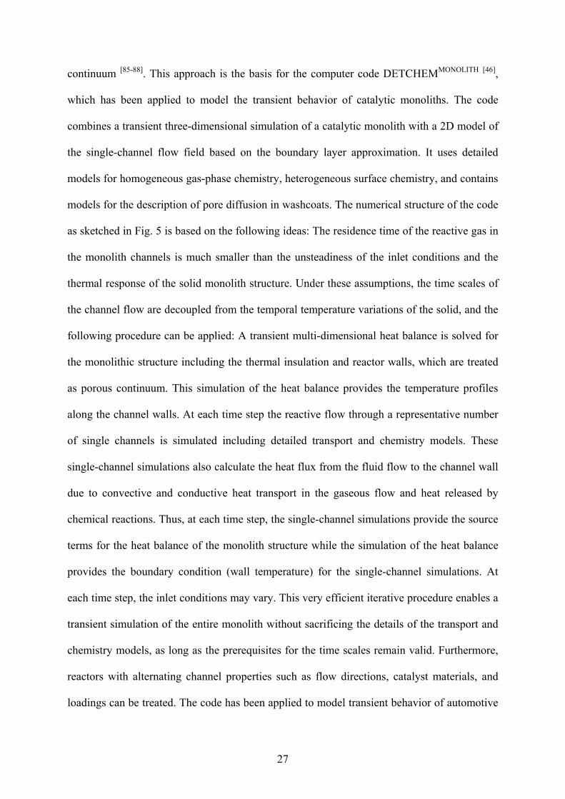
1 Introduction
Catalytic reactors are generally characterized by the complex interaction of various physical
and chemical processes. Monolithic reactors can serve as example, in which partial oxidation
and reforming of hydrocarbons, combustion of natural gas, and the reduction of pollutant
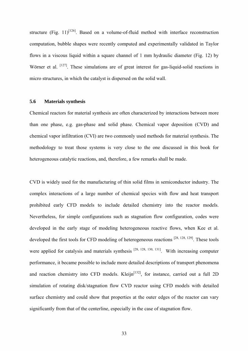
emissions from automobiles are frequently carried out. Figure 1 illustrates the physics and
chemistry in a catalytic combustion monolith that glows at a temperature of about 1300 K due
to the exothermic oxidation reactions. In each channel of the monolith, the transport of
momentum, energy, and chemical species occurs not only in flow (axial) direction, but also in
radial direction. The reactants diffuse to the inner channel wall, which is coated with the
catalytic material, where the gaseous species adsorb and react on the surface. The products
and intermediates desorb and diffuse back into the bulk flow. Due to the high temperatures,
the chemical species may also react homogeneously in the gas phase. In catalytic reactors, the
catalyst material is often dispersed in porous structures like washcoats or pellets. Mass
transport in the fluid phase and chemical reactions are then superimposed by diffusion of the
species to the active catalytic centers in the pores. The temperature distribution depends on
the interaction of heat convection and conduction in the fluid, heat release due to chemical
reactions, heat transport in the solid material, and thermal radiation. If the feed conditions
vary in time and space and/or heat transfer occurs between the reactor and the ambience, a
non-uniform temperature distribution over the entire monolith will result, and the behavior
will differ from channel to channel.
3
Today, the challenge in catalysis is not only the development of new catalysts to synthesize a
desired product, but also the understanding of the interaction of the catalyst with the
surrounding reactive flow field. Sometimes, the exploitation of these interactions can lead to
the desired product selectivity and yield. Hence, a better understanding of gas-solid flows in
chemical reactors is understood as a critical need in chemical technology calling for the
development of reliable simulation tools that integrate detailed models of reaction chemistry
and computational fluid dynamics (CFD) modeling of macro-scale flow structures.
Computational fluid dynamics is able to predict very complex flow fields, even combined
with heat transport, due to the recently developed numerical algorithms and the availability of
faster and bigger (memory) computer hardware. The consideration of detailed models for
chemical reactions, in particular for heterogeneous reactions, however, is still very
challenging due to the large number of species mass conservation equations, their highly non-
linear coupling, and the wide range of time scales introduced by the complex reaction
networks.
This chapter introduces the application of CFD simulations to obtain a better understanding of
the interactions between mass and heat transport and chemical reactions in catalytic reactors.
Concepts for modeling and numerical simulation of catalytic reactors are presented, which
describe the coupling of the physical and chemical processes in detail. The elementary
kinetics and dynamics as well as ways for modeling the intrinsic chemical reactions rates
(microkienetics) by various approaches such as Monte Carlo (MC), Mean Field
Approximation (MF), and lumped kinetics are discussed in the first chapters of this book. In
this chapter, it is assumed that models exist that can compute the local heterogeneous but also
homogeneous reaction rate as function of the local conditions such as temperature and species
concentration in the gas-phase and of the local and temporal state of the catalyst. These
4
chemical source terms are here coupled with the fluid flow and used to numerically simulate
the catalytic reactor.
The ultimate objective of CFD simulations of catalytic reactors is (1) to understand the
interactions of physics (mass and heat transport) and chemistry in the reactor, (2) to support
reactor design and engineering, and (3) eventually, to find optimized operating conditions for
the maximization of the yield of the desired product and minimization of undesired side-
products or pollutants. Though computational fluid dynamics covers a wide range of
problems, reaching from the simulation of the flow around airplanes to laminarization of
turbulent flows entering a micro channel, this chapter focuses on the principal ideas and the
potential applications of CFD in heterogeneous catalysis; textbooks[1, 2] and specific literature
are frequently referenced for more details. Specific examples taken from literature and our
own work will be used for illustration of the state-of-the-art CFD simulation of chemical
reactors with heterogeneously catalyzed reactions. The next chapters of the book will cover
some specific topics of numerical simulation of catalytic reactors in more detail.
5
2 Modeling of reactive flows
2.1 Governing equations of multi-component flows
As long as a fluid can be treated as a continuum, the most accurate description of the flow
field of multi-component mixtures is given by the transient three-dimensional (3D) Navier-
Stokes equations coupled with the energy and species governing equations, which will be
summarized in this section. More detailed introductions into fluid dynamics and transport
phenomena can be found in a number of textbooks [1-5]. Other alternative concepts such as
Lattice-Boltzmann models have also been discussed for simulation of catalytic reactors as
introduced in Section 5.1.
Governing equations, which are based on conservation principles, can be derived by
consideration of the flow within a certain spatial region, which is called the control volume.
The principle of mass conservation leads to the mass continuity equation
mS
x
v
t i
i
, (1)
with being the mass density, t the time, xi (i=1,2,3) are the Cartesian coordinates, and vi the
velocity components. The source term Sm vanishes unless mass is either deposited on or
ablated from the solid surfaces. The Einstein convention is used here, i.e., whenever the same
index appears twice in any term, summation over that index is implied, except if the index
refers to a chemical species. The principle of momentum conservation for Newtonian fluids
leads to three scalar equations for the momentum components vi
i
j
ij
ij
jii gxx
p
x
vv
t
v
, (2)
where p is the static pressure, ij is the stress tensor, gi are the components of the gravitational
acceleration. The above equation is written for Cartesian coordinates. Gravity, the only body
6
force taken into account, can often be neglected when modeling catalytic reactors. The stress
tensor is given as
k
kij
i
j
j
iij x
v
x
v
x
v
3
2 . (3)
Here, and are the bulk viscosity and mixture viscosity, respectively, and ij is the
Kronecker delta, which is unity for i=j, else zero. The bulk viscosity vanishes for low density
mono-atomic gases and is also commonly neglected for dense gases and liquids[1]. The
coupled mass continuity and momentum governing equations have to be solved for the
description of the flow field.
In multi-component mixtures, not only the flow field is of interest but also mixing of the
chemical species and reactions among them, which can be described by an additional set of
partial differential equations. Here, the mass mi of each of the Ng gas-phase species obeys a
conservation law that leads to
hom,i
j
ji
j
iji Rx
j
x
Yv
t
Y
, (4)
with Yi is the mass fraction of species i in the mixture (Yi = mi/m) with m as total mass, Rihom is
the net rate of production due to homogeneous chemical reactions. The components ji,j of the
diffusion mass flux caused by concentration and temperature gradients are often modeled by
the mixture-average formulation [6]:
j
i
j
ii
i
iji x
T
T
D
x
XD
X
Yj
T
M, . (5)
DiM is the effective diffusion coefficient of species i in the mixture, Di
T is the thermal
diffusion coefficient, which is significant only for light species, and T is the temperature. The
molar fraction Xi is related to the mass fraction Yi using the species molar masses Mi by
7
i
i
N
jj
ji M
Y
MY
X
g
1
1. (6)
Heat transport and heat release due to chemical reactions lead to spatial and temporal
temperature distributions in catalytic reactors. The corresponding governing equation for
energy conservation is commonly expressed in terms of the specific enthalpy h:
h
, Sx
v
x
pv
t
p
x
j
x
hv
t
h
k
jjk
jj
j
jq
j
j
, (7)
with Sh being the heat source, for instance due to thermal radiation. In multi-component
mixtures, diffusive heat transport is significant due to heat conduction and mass diffusion,
hence
g
1,,
N
ijii
jjq jh
x
Tj . (8)
is the thermal conductivity of the mixture. The temperature is then related to the enthalpy by
the definition of the mixture specific enthalpy
g
1
N
iii ThYh , (9)
with hi being the specific enthalpy of species i, which is a monotonic increasing function of
temperature. The temperature is then commonly derived from Eq. (9) for known h and Yi.
Heat transport in solids such as reactor walls and catalyst materials can also be modeled by an
enthalpy equation, for instance in the form of
hS
x
T
xt
h
jj
, (10)
where h is the specific enthalpy and λ the thermal conductivity of the solid material. Sh
accounts for heat sources, for instance due to heat release by chemical reactions and electric
or radiative heating of the solid.
8
This system of governing equations is closed by the equation of state to relate the
thermodynamic variables density ρ, pressure p, and temperature T. The simplest model of this
relation for gaseous flows is the ideal gas equation
g
1
N
iiiMX
RTp
, (11)
with the universal gas constant R = 8.314 J mol-1 K-1.
The transport coefficients μ, DiM, Di
T, and λ appearing in Eqs. (3, 5, 8) depend on temperature
and mixture composition. They are derived from the transport coefficients of the individual
species and the mixture composition by applying empirical approximations [1, 2, 4], which
eventually lead to two physical parameters for each species, a characteristic diameter (the
Lennard-Jones collision diameter), σi, and a characteristic energy (the Lennard-Jones potential
well depth), i, which can be taken from data bases [7].
The specific enthalpy hi is a function of temperature and can be expressed in terms of the heat
capacity
T
T
ipii TTcThhref
d)(,ref , (12)
where cp,i is the specific heat capacity at constant pressure. The specific standard enthalpy of
formation Δh0f,298,i can be used as integration constant hi(Tref = 298.15 K, p0 = 1 bar).
Experimentally determined and estimated standard enthalpies of formation, standard
entropies, and temperature dependent heat capacities can be found in data bases [8-10] or
estimated by Benson’s additivity rules [11].
2.2 Turbulent flows
9
Turbulent flows are characterized by continuous fluctuations of velocity, which can lead to
fluctuations in scalars such as density, temperature, and mixture composition. Turbulence can
be desired in catalytic reactors to enhance mixing and reduce mass transfer limitations but is
also unwanted due to the increased pressure drop and energy dissipation. An adequate
understanding of all facets of turbulent flows is still missing [4, 12, 13]. In the area of catalytic
systems, some progress has recently been made in turbulent flow modeling, e.g. in
catalytically stabilized combustion [14, 15]. The Navier-Stokes equations as presented above are
in principal able to model turbulent flows (Direct Numerical Simulation). However in
practice, the solutions of the Navier-Stokes equations for turbulent flows in technical reactors
demand a prohibitive amount of computational time due to the huge number of grid points
needed to resolve the small scales of turbulence. Therefore, several concepts were developed
to model turbulent flows by the solution of averaged governing equations. However, the
equation system is not closed, that means a model has to be set up to describe the so-called
Reynold stresses that are the correlations between the velocity fluctuations and the
fluctuations of all the quantities of the flow (velocity, enthalpy, mass fractions). The k - -
model [16] is one of the most widely used concept for modeling the Reynold stresses at high
Reynolds numbers, which adds two additional partial differential equations for the description
of the turbulent kinetic energy, k, and the dissipation rate, to the governing equations.
Although the model has well-known deficiencies, it is today implemented in most commercial
CFD codes and also widely used for the simulation of catalytic reactors. Recently, turbulent
flow field simulations are often based on Large-Eddy-Simulation (LES), which combines
DNS for the larger scales with a turbulence model, e.g. k - - model, for the unresolved
smaller scales.
Aside form this closure problem, one still has to specify the averaged chemical reaction rates
[4, 12]. Because of the strong non-linearity of the rate coefficients due to the exponential
10
dependence on temperature and the power-law dependence on partial pressure, the source
terms of chemical reactions in turbulent flows cannot be computed using average
concentrations and temperature. Here, probability density functions (PDFs) [4], either derived
by transport equations [13] or empirically constructed [17], are used to take the turbulent
fluctuations into account when calculating the chemical source terms. For the simulation of
reactions on catalysts, it is important to use appropriate models for the flow laminarization at
the solid surface.
2.3 Three-phase flow
Three-phase flows involve the participation of solid, liquid, and gaseous phases. In certain
cases the solid phase will be a porous medium, and the fluids will flow though the pore
networks. In certain other cases all phases will be mobile and these flows are usually
characterized by various regimes such as particle-ladden flow, fluidized bed flow, slug flow,
bubbly flow etc. Examples for three-phase flow device with chemical reaction are fluidized
bed reactors. They are one of the most important classes of multi-phase reactors used in
chemical, petrochemical, and biochemical processing. Simulating multi-phase reactors is a
challenge due to the numerous physico-chemical processes occurring in the reactor. For
example, one has to account for interactions between and among various phases, lift,
buoyancy, virtual mass forces, particle agglomeration, and bubble coalescence [18].
Either the Euler-Lagrange model or Euler-Euler model can be used to solve the three-phase
flow problem. The former adopts a continuum description for the liquid phase and tracks the
discrete phases using Lagrangian particle trajectory analysis. The Euler-Euler model is based
on the concept of interpenetrating continua. Here all the phases are treated as continua with
properties analogous to those of a fluid. That is conservation equations are derived for each of
the phases and constitutive relations that are empirical in nature closes the equation set.
11
Therefore, the accuracy of this method heavily relies on the empirical constitutive relations
used. Furthermore, this approach has limitation in predicting certain characteristics of discrete
flow. For instance, the method can not account for particle size effect, particle agglomeration,
bubble coalescence, and bubble breakage. On the other hand, the Euler-Lagrange model has
empirical equations and can provide detailed information of discrete phases. However, it is
computationally more expensive. A detailed description of three-phase flow modeling is
beyond the scope of this chapter and interested readers can refer to textbooks [19-21].
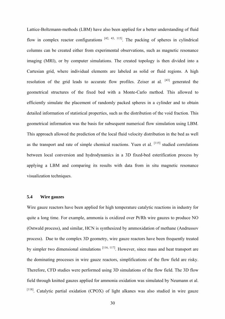
2.4 Momentum and energy equations for porous media
Porous media are present everywhere in catalytic reactors [22, 23], for instance fixed-bed
and reactive distillation devices. These multi-phase reactors are of multi-scale structure, i.e.
single particles, particle clusters/bubbles and reactor vessel, and of multiple physics, i.e.
hydrodynamics, heat and mass transfer, and reaction kinetics. The formation of complex
structures/patterns in each regime is a result of a compromise between dominant mechanisms
at multiple scales. Coupling of hydrodynamics, heat and mass transfer, and reaction kinetics
takes place at molecular and particle levels where conductive and convective transfer and
diffusion within the internal pores of the catalyst are accompanied by the adsorption, surface
reaction and desorption of reactant and product on the surface. Even though this complexity is
challenging for CFD simulations, computations are a promising tool to achieve a better
understanding of multi-phase reactors.
32
A detailed description of the fundamentals and modeling attempts of these multi-phase
reactors is beyond the scope of this chapter, here it is referred to general textbooks[19-21].
Instead, few examples may serve as illustration of the potential of CFD simulations of
reactors with multi-phase flow fields.
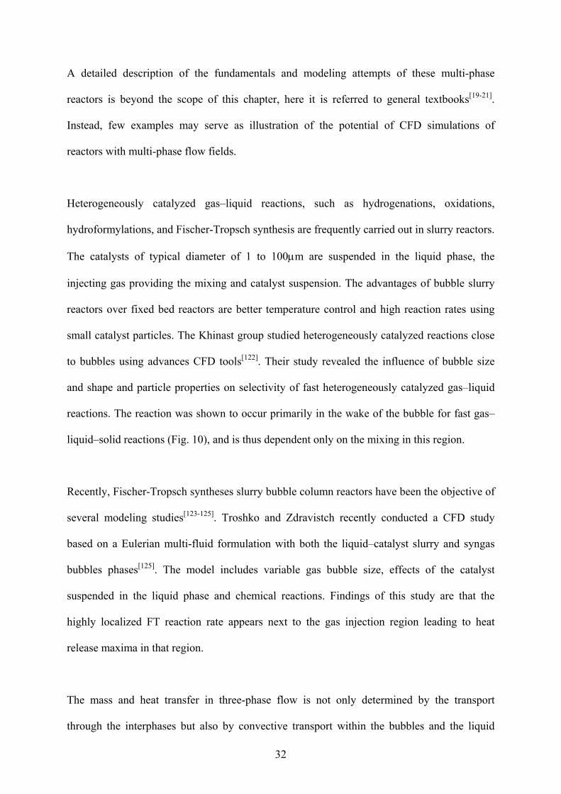
Heterogeneously catalyzed gas–liquid reactions, such as hydrogenations, oxidations,
hydroformylations, and Fischer-Tropsch synthesis are frequently carried out in slurry reactors.
The catalysts of typical diameter of 1 to 100m are suspended in the liquid phase, the
injecting gas providing the mixing and catalyst suspension. The advantages of bubble slurry
reactors over fixed bed reactors are better temperature control and high reaction rates using
small catalyst particles. The Khinast group studied heterogeneously catalyzed reactions close
to bubbles using advances CFD tools[122]. Their study revealed the influence of bubble size
and shape and particle properties on selectivity of fast heterogeneously catalyzed gas–liquid
reactions. The reaction was shown to occur primarily in the wake of the bubble for fast gas–
liquid–solid reactions (Fig. 10), and is thus dependent only on the mixing in this region.
Recently, Fischer-Tropsch syntheses slurry bubble column reactors have been the objective of
several modeling studies[123-125]. Troshko and Zdravistch recently conducted a CFD study
based on a Eulerian multi-fluid formulation with both the liquid–catalyst slurry and syngas
bubbles phases[125]. The model includes variable gas bubble size, effects of the catalyst
suspended in the liquid phase and chemical reactions. Findings of this study are that the
highly localized FT reaction rate appears next to the gas injection region leading to heat
release maxima in that region.
The mass and heat transfer in three-phase flow is not only determined by the transport
through the interphases but also by convective transport within the bubbles and the liquid
33
structure (Fig. 11)[126]. Based on a volume-of-fluid method with interface reconstruction
computation, bubble shapes were recently computed and experimentally validated in Taylor
flows in a viscous liquid within a square channel of 1 mm hydraulic diameter (Fig. 12) by
Wörner et al. [127]. These simulations are of great interest for gas-liquid-solid reactions in
micro structures, in which the catalyst is dispersed on the solid wall.
5.6 Materials synthesis
Chemical reactors for material synthesis are often characterized by interactions between more
than one phase, e.g. gas-phase and solid phase. Chemical vapor deposition (CVD) and
chemical vapor infiltration (CVI) are two commonly used methods for material synthesis. The
methodology to treat those systems is very close to the one discussed in this book for
heterogeneous catalytic reactions, and, therefore, a few remarks shall be made.
CVD is widely used for the manufacturing of thin solid films in semiconductor industry. The
complex interactions of a large number of chemical species with flow and heat transport
prohibited early CFD models to include detailed chemistry into the reactor models.
Nevertheless, for simple configurations such as stagnation flow configuration, codes were
developed in the early stage of modeling heterogeneous reactive flows, when Kee et al.
developed the first tools for CFD modeling of heterogeneous reactions [28, 128, 129]. These tools
were applied for catalysis and materials synthesis [28, 128, 130, 131]. With increasing computer
performance, it became possible to include more detailed descriptions of transport phenomena
and reaction chemistry into CFD models. Kleijn[132], for instance, carried out a full 2D
simulation of rotating disk/stagnation flow CVD reactor using CFD models with detailed
surface chemistry and could show that properties at the outer edges of the reactor can vary
significantly from that of the centerline, especially in the case of stagnation flow.
34
Modeling CVI is more challenging compared to CVD due to the temporal densification of the
porous substrate and hence the changing surface area. These changes significantly influence
the interaction between the gas-phase and the surface kinetics. Therefore, one has to
incorporate additional model equations that describe the temporal changes in porosity and
surface area into the CFD models. Li et al. modeled the chemical vapor infiltration (CVI) of
hydrocarbons for the synthesis of carbon-carbon composites. They coupled the CVI model
with COMSOL to simulate the densification of the porous substrate as a function of time[133,
134]and studied the densification of a porous carbon felt using CH4 precursor. CFD simulations
have also found their way into modeling of the synthesis of catalytic particles by flame
synthesis[135], carbon nanotubes[136], and fibrous active materials [137, 138], to name just few
more examples related to catalysis.
5.7 Electrocatalytic devices
CFD simulations using heterogeneous reactions are extensively applied to fundamental
research pertaining to electrochemical systems, as discussed in more detail for SOFC
modeling in Chapter 6. Also battery dynamics studied using CFD techniques give insightful
understanding of its discharge characteristics. Several one-dimensional models are reported in
the literature that simulates the electrolyte transport and discharge characteristics[139, 140].
Although the one-dimensional models are simple and efficient in predicting the discharge
characteristics of battery systems, multi-dimensional models without any ad hoc
approximations can be very valuable in the fundamental understanding of processes that occur
in battery systems. The ability to visualize flow patterns during operation of a device is a
uniqueness of CFD, which is very difficult if not impossible to realize in pure
experimentation. Gu et al., for instance, developed a CFD model to predict the transient
behavior of electric-vehicle lead acid batteries during charge and discharge processes[141]. The
growing interest in lithium ion batteries also lead to first CFD applications in this field[142].
35
CFD simulation has also been used to understand experimentally observed phenomena in
electro-catalytic flow cells, in which mass transport interacts with the electric and chemical
processes leading to a complex dependence of the Faradaic current on the potential[143].
6 Summary and outlook
From a reaction engineering perspective, computational fluid dynamics simulations have
matured into a powerful tool for understanding mass and heat transport in catalytic reactors.
Initially, CFD calculations focused on a better understanding of mixing, mass transfer to
enhance reaction rates, diffusion in porous media and heat transfer. Over the last decade, the
flow field and heat transport models have also been coupled with models for heterogeneous
chemical reactions. So far, most of these models are based on the mean field approximation,
in which the local state of the surface is described by its coverage with adsorbed species
averaged on a microscopic scale. The currently increasing research activities on surface
reactions at practical conditions will certainly boost the application of CFD codes that
combine fluid flow and chemistry. New insights into the complexity of heterogeneous
catalysis, however, will also reveal the demand for more sophisticated chemistry models.
Their implementation into CFD simulations will then require even more sophisticated
numerical algorithms and computer hardware. Hence, CFD simulations of reactive systems
will remain a very active field and the implementation of more adequate and complex models
will continue.
The simulation results will always remain a reflection of the models and physical parameters
applied. The careful choice of the sub models (geometry, turbulence, diffusion, species, and
reactions involved, etc.) and the physical parameters (inlet and boundary conditions,
36
conductivity, permeability, viscosity, etc.) is a precondition for reliable simulation results.
Therefore, only the use of appropriate models and parameters, which describe all significant
processes in the reactor, can lead to reliable results. Furthermore, numerical algorithms never
give the accurate solution of the model equations but only an approximated solution. Hence,
error estimation is needed. Having these crucial issues in mind, CFD can really serve as a
powerful tool in understanding the behavior in catalytic reactors and in supporting the design
and optimization of reactors and processes.
Acknowledgments
The authors would like to thank R.J. Kee (Colorado School of Mines), S. Tischer, M. Wörner,
L. Maier (all Karlsruhe Institute of Technology) for very stimulating discussions on modeling
and simulation of chemical reactors and Y. Dedecek (Karlsruhe Institute of Technology) for
editorial corrections of the manuscript. Financial support by the German Research Foundation
(DFG) and the Helmholtz Association is gratefully acknowledged.
37
References [1] R. B. Bird, W. E. Stewart, E. N. Lightfoot, Transport Phenomena, 2nd ed., John
Wiley & Sons, Inc., New York, 2001. [2] R. J. Kee, M. E. Coltrin, P. Glarborg, Chemically Reacting Flow, Wiley-Interscience,
2003. [3] S. V. Patankar, Numerical Heat Transfer and Fluid Flow, McGraw-Hill, New York,
1980. [4] J. Warnatz, R. W. Dibble, U. Maas, Combustion, Physical and Chemical
Fundamentals, Modeling and Simulation, Experiments, Pollutant Formation, Springer-Verlag, New York, 1996.
[5] R. E. Hayes, S. T. Kolaczkowski, Introduction to Catalytic Combustion, Gordon and Breach Science Publ., Amsterdam, 1997.
[6] J. O. Hirschfelder, C. F. Curtiss, R. B. Bird, Molecular Theory of Gases and Liquids, rev. ed., Wiley, New York, 1964.
[7] R. J. Kee, G. Dixon-Lewis, J. Warnatz, M. E. Coltrin, J. A. Miller, A Fortran Computer Code Package for the Evaluation of Gas-Phase Multicomponent Transport Properties, SAND86-8246, Sandia National Laboratories, 1986.
[8] M. W. Chase Jr., C. A. Davis, J. R. Downey Jr., D. J. Frurip, R. A. McDonald, A. N. Syverud, Journal of Physical and Chemical Reference Data 1985, 14, 1.
[9] R. J. Kee, F. M. Rupley, J. A. Miller, The Chemkin Thermodynamic Database, SAND87-8215, Sandia National Laboratories, Livermore, 1987.
[10] A. Burcat, in Combustion chemistry (Ed.: W. C. Gardiner), Springer, New York, 1984, p. 455.
[11] S. W. Benson, Thermochemical Kinetics, John Wiley & Sons, New York, 1976. [12] P. A. Libby, F. A. Williams, Turbulent Reactive Flow, Academic Press, London,
1993. [13] S. B. Pope, Progress in Energy and Combustion Science 1985, 11, 119. [14] C. Appel, J. Mantzaras, R. Schaeren, R. Bombach, A. Inauen, Combustion and Flame
2005, 140, 70. [15] J. Mantzaras, C. Appel, P. Benz, U. Dogwiler, Catalysis Today 2000, 59, 3. [16] B. E. Laudner, D. B. Spalding, Mathematical models of turbulence, Academic Press,
London/New York, 1972. [17] E. Gutheil, H. Bockhorn, Physicochemical Hydrodynamics 1987, 9, 525. [18] X. Y. Zhang, G. Ahmadi, Chemical Engineering Science 2005, 60, 5089. [19] H. A. Jakobsen, Chemical Reactor Modeling: Multiphase Reactive Flows Springer-Verlag, Heidelberg, 2008. [20] C. T. Crowe, J. D. Schwarzkopf, M. Sommerfeld, Y. Tsuji, Multiphase Flows with
Droplets and Particles, CRC Press, 1998. [21] M. Ishii, T. Hibiki, Thermo-fluid Dynamics of Two-Phase Flow, Springer, 2006. [22] R. Aris, The Mathematical Theory of Diffusion and Reaction in Permeable Catalysts,
Clarendon Press, Oxford, 1975. [23] F. Keil, Diffusion und Chemische Reaktionen in der Gas-Feststoff-Katalyse, Springer-
Verlag, Berlin, 1999. [24] F. J. Keil, Catalysis Today 2000, 53, 245. [25] O. Bey, G. Eigenberger, Chemical Engineering Science 1997, 52, 1365. [26] M. Giese, K. Rottschafer, D. Vortmeyer, American Institute of Chemical Engineering
Journal 1998, 44, 484. [27] M. Winterberg, E. Tsotsas, A. Krischke, D. Vortmeyer, Chemical Engineering Science
2000, 55, 967.
38
[28] M. E. Coltrin, R. J. Kee, F. M. Rupley, SURFACE CHEMKIN (Version 4.0): A Fortran Package for Analyzing Heterogeneous Chemical Kinetics at a Solid-Surface - Gas-Phase Interface, SAND91-8003B, Sandia National Laboratories, 1991.
[29] O. Deutschmann, R. Schmidt, F. Behrendt, J. Warnatz, Proceedings of the Combustion Institute 1996, 26, 1747.
[30] L. L. Raja, R. J. Kee, L. R. Petzold, Proceedings of the Combustion Institute 1998, 27, 2249.
[31] W. Boll, S. Tischer, O. Deutschmann, Industrial & Engineering Chemistry Research 2010, 49, 10303.
[32] S. B. Kang, H. J. Kwon, I. S. Nam, Y. I. Song, S. Oh, Industrial & Engineering Chemistry Research 2011, accepted for publication.
[33] D. Papadias, L. Edsberg, P. H. Björnbom, Catalysis Today 2000, 60, 11. [34] E. Mason, A. Malinauskas, Gas Transport in Porous Media: The Dusty-Gas Model,
American Elsevier, New York, 1983. [35] P. Kerkhof, M. A. M. Geboers, American Institute of Chemical Engineering Journal
2005, 51, 79. [36] P. Kerkhof, Chemical Engineering Journal 1996, 64, 319. [37] V. V. Ranade, Computational Flow Modeling for Chemical Reactor Engineering,
Acadamic Press, 2002. [38] R. E. Hayes, S. T. Kolaczkowski, W. J. Thomas, Computers & Chemical Engineering
1997, 16, 654. [39] D. S. Burnett, Finite Elemnet Analysis, Addison-Wesley Publ. Comp., Reading, 1987. [40] S. Succi, The Lattice Boltzmann Equation for Fluid Dynamics and Beyond, Oxford
University Press, 2001. [41] S. P. Sullivan, F. M. Sani, M. L. Johns, L. F. Gladden, Chemical Engineering Science
2005, 60, 3405. [42] H. Freund, T. Zeiser, F. Huber, E. Klemm, G. Brenner, F. Durst, G. Emig, Chemical
Engineering Science 2003, 58, 903. [43] T. Zeiser, P. Lammers, E. Klemm, Y. W. Li, J. Bernsdorf, G. Brenner, Chemical
Engineering Science 2001, 56, 1697. [44] R. J. Kee, F. M. Rupley, J. A. Miller, M. E. Coltrin, J. F. Grcar, E. Meeks, H. K.
Moffat, A. E. Lutz, G. Dixon-Lewis, M. D. Smooke, J. Warnatz, G. H. Evans, R. S. Larson, R. E. Mitchell, L. R. Petzold, W. C. Reynolds, M. Caracotsios, W. E. Stewart, P. Glarborg, C. Wang, O. Adigun, CHEMKIN, 3.6 ed., Reaction Design, Inc., www.chemkin.com, San Diego, 2000.
[45] D. G. Goodwin, CANTERA. An open-source, extensible software suite for CVD process simulation, www.cantera.org, 2003.
[46] O. Deutschmann, S. Tischer, C. Correa, D. Chatterjee, S. Kleditzsch, V. M. Janardhanan, DETCHEM software package, 2.0 ed., www.detchem.com, Karlsruhe, 2004.
[47] Fluent, Fluent Incorporated, www.fluent.com, Lebanon, NH, 2005. [48] in CD-adapco, London Office, 200 Shepherds Bush Road, London, W6 7NY, United
Kingdom, www.cd-adapco.com. [49] FIRE, AVL LIST GmbH, www.avl.com, Graz, Austria, 2005. [50] CFD-AC+, CFD Research Corporation, www.cfdrc.com, Huntsville, AL, 2005. [51] CFX, www-waterloo.ansys.com, 2005. [52] J. Shadid, S. Hutchinson, G. Hennigan, H. Moffat, K. Devine, A. G. Salinger, Parallel
[54] K. E. Brenan, S. L. Campbell, L. R. Petzold, Numerical Solution of Initial-Value Problems in Differential-Algebraic Equations, 2nd ed., SIAM, Philadelphia, PA, 1996.
[55] A. C. Hindmarsh, in Scientific Computing (Ed.: R. S. Stepleman), North Holland Publishing Co., Amsterdam, 1983, pp. 55.
[56] P. Deuflhardt, E. Hairer, J. Zugk, Numerische Mathematik 1987, 51, 501. [57] P. Deuflhard, U. Nowak, Progress in Scientific Computing 1987, 7, 37. [58] P. N. Brown, G. D. Byrne, A. C. Hindmarsh, SIAM Journal on Scientific and
Statistical Computing 1989, 10, 1038. [59] The Trilinos Project, Sandia National Laboratories, http://trilinos.sandia.gov/, 2011. [60] U. M. Ascher, L. R. Petzold, Computer Methods for Ordinary Differential Equations
and Differential-Algebraic Equations, SIAM, Philadelphia, PA, 1998. [61] C. Appel, J. Mantzaras, R. Schaeren, R. Bombach, B. Kaeppeli, A. Inauen,
Proceedings of the Combustion Institute 2003, 29, 1031. [62] R. E. Hayes, B. Liu, M. Votsmeier, Chemical Engineering Science 2005, 60, 2037. [63] R. E. Hayes, B. Liu, R. Moxom, M. Votsmeier, Chemical Engineering Science 2004,
59, 3169. [64] N. Mladenov, J. Koop, S. Tischer, O. Deutschmann, Chemical Engineering Science
2010, 65, 812. [65] O. Deutschmann, R. Schwiedernoch, L. Maier, D. Chatterjee, in Natural Gas
Conversion VI, Studies in Surface Science and Catalysis, Vol. 136 (Eds.: E. Iglesia, J. J. Spivey, T. H. Fleisch), Elsevier, Alaska, 2001, pp. 251.
[66] H. Schlichting, K. Gersten, Boundary-Layer Theory, 8th ed., Springer-Verlag, Heidelberg, 1999.
[67] L. L. Raja, R. J. Kee, O. Deutschmann, J. Warnatz, L. D. Schmidt, Catalysis Today 2000, 59, 47.
[68] M. Hartmann, L. Maier, H. D. Minh, O. Deutschmann, Combustion and Flame 2010, 157, 1771.
[69] R. Schwiedernoch, S. Tischer, C. Correa, O. Deutschmann, Chemical Engineering Science 2003, 58, 633.
[70] S. Karagiannidis, J. Mantzaras, G. Jackson, K. Boulouchos, Proceedings of the Combustion Institute 2007, 31, 3309.
[71] M. Maestri, D. G. Vlachos, A. Beretta, P. Forzatti, G. Groppi, E. Tronconi, Topics in Catalysis 2009, 52, 1983.
[72] A. Beretta, G. Groppi, M. Lualdi, I. Tavazzi, P. Forzatti, Industrial & Engineering Chemistry Research 2009, 48, 3825.
[73] R. Horn, N. J. Degenstein, K. A. Williams, L. D. Schmidt, Catalysis Letters 2006, 110, 169.
[74] M. Hartmann, T. Kaltschmitt, O. Deutschmann, Catalysis Today 2009, 147, S204. [75] N. Hebben, C. Diehm, O. Deutschmann, Appl. Catalysis A: General 2010,
doi:10.1016/j.apcata.2010.08.055. [76] T. Kaltschmitt, L. Maier, O. Deutschmann, Proceedings of the Combustion Institute
2010, 33, doi: 10.1016/j.proci.2010.05.050 [77] R. E. Hayes, S. T. Kolaczkowski, Catalysis Today 1999, 47, 295. [78] G. Veser, J. Frauhammer, Chemical Engineering Science 2000, 55, 2271. [79] D. K. Zerkle, M. D. Allendorf, M. Wolf, O. Deutschmann, Journal of Catalysis 2000,
196, 18. [80] R. E. Hayes, S. T. Kolaczkowski, W. J. Thomas, Computers & Chemical Engineering
1992, 16, 645.
40
[81] R. Wanker, H. Raupenstrauch, G. Staudinger, Chemical Engineering Science 2000, 55, 4709.
[82] R. Wanker, M. Berg, H. Raupenstrauch, G. Staudinger, Chemical Engineering & Technology 2000, 23, 535.
[83] S. T. Kolaczkowski, Catalysis Today 1999, 47, 209. [84] S. Mazumder, D. Sengupta, Combustion and Flame 2002, 131, 85. [85] R. Jahn, D. Snita, M. Kubicek, M. Marek, Catalysis Today 1997, 38, 39. [86] G. C. Koltsakis, P. A. Konstantinidis, A. M. Stamatelos, Applied Catalysis B:
Environmental 1997, 12, 161. [87] S. Tischer, C. Correa, O. Deutschmann, Catalysis Today 2001, 69, 57. [88] S. Tischer, O. Deutschmann, Catalysis Today 2005, 105, 407. [89] L. Maier, M. Hartmann, S. Tischer, O. Deutschmann, Combustion and Flame 2011,
158, 796. [90] M. Hartmann, L. Maier, O. Deutschmann, Appl. Catalysis A: General 2010,
doi:10.1016/j.apcata.2010.08.051. [91] J. Windmann, J. Braun, P. Zacke, S. Tischer, O. Deutschmann, J. Warnatz, SAE
Technical Paper 2003, 2003-01-0937. [92] J. Braun, T. Hauber, H. Többen, J. Windmann, P. Zacke, D. Chatterjee, C. Correa, O.
Deutschmann, L. Maier, S. Tischer, J. Warnatz, SAE Technical Paper 2002, 2002-01-0065.
[93] S. Tischer, Y. Jiang, K. W. Hughes, M. D. Patil, M. Murtagh, SAE Technical paper 2007, 2007-01-1071.
[94] J. Koop, O. Deutschmann, Applied Catalysis B-Environmental 2009, 91, 47. [95] S. S. E. H. Elnashaie, S. S. Elnashaie, Modelling, Simulation and Optimization of
Industrial Fixed Bed Catalytic Reactors, G+B Gordon and Breach, 1995. [96] A. G. Dixon, M. Nijemeisland, Industrial & Engineering Chemistry Research 2001,
40, 5246. [97] M. Bizzi, G. Saracco, R. Schwiedernoch, O. Deutschmann, AIChE Journal 2004, 50,
1289. [98] M. Bauer, R. Adler, Chemical Engineering & Technology 2003, 26, 545. [99] J. P. Sorensen, W. E. Stewart, Chemical Engineering Science 1974, 29, 827. [100] M. T. Dalman, J. H. Merkin, C. McGreavy, Computers & Fluids 1986, 14, 267. [101] B. Lloyd, R. Boehm, Numerical Heat Transfer Part A - Applications 1994, 26, 237. [102] K. Debus, H. Nirschl, A. Delgado, V. Denk, Chemie Ingenieur Technik 1998, 70, 415. [103] S. A. Logtenberg, M. Nijemeisland, A. G. Dixon, Chemical Engineering Science
1999, 54, 2433. [104] H. P. A. Calis, J. Nijenhuis, B. C. Paikert, F. M. Dautzenberg, C. M. van den Bleek,
Chemical Engineering Science 2001, 56, 1713. [105] C. F. Petre, F. Larachi, I. Iliuta, B. P. A. Grandjean, Chemical Engineering Science
2003, 58, 163. [106] A. G. Dixon, M. E. Taskin, M. Nijemeisland, E. H. Stitt, Chemical Engineering
Science 2008, 63, 2219. [107] E. Ranzi, et al., http://www.chem.polimi.it/CRECKModeling/kinetic.html 2007. [108] A. G. Dixon, M. E. Taskin, E. H. Stitt, M. Nijemeisland, Chemical Engineering
Science 2007, 62, 4963. [109] A. G. Dixon, M. Nijemeisland, E. H. Stitt, Industrial & Engineering Chemistry
Research 2005, 44, 6342. [110] M. Behnam, A. G. Dixon, M. Nijemeisland, E. H. Stitt, Industrial & Engineering
Chemistry Research 2005, 49, 10641. [111] M. Nijemeisland, A. G. Dixon, American Institute of Chemical Engineering Journal
2004, 50, 906.
41
[112] V. Yakhot, S. A. Orszag, Physical Review Letters 1986, 57, 1722. [113] B. E. Laudner, D. B. Spalding, Computer Methods in Applied Mathematics and
Engineering 1974, 3, 169. [114] M. Behnam, A. G. Dixon, M. Nijemeisland, E. H. Stitt, Industrial & Engineering
Chemistry Research, 49, 10641. [115] E. H. L. Yuen, A. J. Sederman, F. Sani, P. Alexander, L. F. Gladden, Chemical
Engineering Science 2003, 58, 613. [116] V. P. Zakharov, I. A. Zolotarskii, V. A. Kuzmin, Chemical Engineering Journal 2003,
91, 249. [117] R. P. O´Connor, L. D. Schmidt, O. Deutschmann, American Institute of Chemical
Engineering Journal 2002, 48, 1241. [118] J. Neumann, H. Golitzer, A. Heywood, I. Ticu, Revista De Chimie 2002, 53, 721. [119] C. R. H. de Smet, M. H. J. M. de Croon, R. J. Berger, G. B. Marin, J. C. Schouten,
Applied Catalysis A: General 1999, 187, 33. [120] R. Quiceno, O. Deutschmann, J. Warnatz, Applied Catalysis A: General 2005,
submitted. [121] FLUENT, 4.4 ed., Fluent Inc. Lebanon, New Hampshire, 1997. [122] J. A. Raffensberger, B. J. Glasser, J. G. Khinast, Aiche Journal 2005, 51, 1482. [123] G. Lozano-Blanco, J. W. Thybaut, K. Surla, P. Galtier, G. B. Marin, Aiche Journal
2009, 55, 2159. [124] J. M. van Baten, R. Krishna, Industrial & Engineering Chemistry Research 2004, 43,
4483. [125] A. A. Troshko, F. Zdravistch, Chemical Engineering Science 2009, 64, 892. [126] S. Kececi, M. Worner, A. Onea, H. S. Soyhan, Catalysis Today 2009, 147, S125. [127] O. Keskin, M. Worner, H. S. Soyhan, T. Bauer, O. Deutschmann, R. Lange, Aiche
Journal, 56, 1693. [128] M. E. Coltrin, R. J. Kee, G. H. Evans, E. Meeks, F. M. Rupley, J. F. Grcar, Sandia
National Laboratories, 1991. [129] M. E. Coltrin, R. J. Kee, G. Evans, Journal of Electrochemical Society 1989, 136, 819. [130] E. Meeks, R. J. Kee, D. S. Dandy, M. E. Coltrin, Combustion and Flame 1993, 92,
144. [131] B. Ruf, F. Behrendt, O. Deutschmann, J. Warnatz, Surface Science 1996, 352, 602. [132] C. R. Kleijn, Thin Solid Films 2000, 365, 294. [133] A. Li, K. Norinaga, W. G. Zhang, O. Deutschmann, Composites Science and
Technology 2008, 68, 1097. [134] A. J. Li, O. Deutschmann, Chemical Engineering Science 2007, 62, 4976. [135] H. K. Kammler, L. Madler, S. E. Pratsinis, Chemical Engineering & Technology
2001, 24, 583. [136] H. Kim, K. S. Kim, J. Kang, Y. C. Park, K. Y. Chun, J. H. Boo, Y. J. Kim, B. H.
Hong, J. B. Choi, Nanotechnology, 22, 5. [137] O. V. Chub, E. S. Borisova, O. P. Klenov, A. S. Noskov, A. Matveev, I. V. Koptyug,
Catalysis Today 2005, 105, 680. [138] J. De Greef, G. Desmet, G. Baron, Catalysis Today 2005, 105, 331. [139] K. C. Tsaur, R. Pollard, Journal of the Electrochemical Society 1984, 131, 975. [140] T. I. Evans, T. V. Nguyen, R. E. White, Journal of the Electrochemical Society 1989,
136, 328. [141] W. B. Gu, C. Y. Wang, B. Y. Liaw, Journal of the Electrochemical Society 1997, 144,
2053. [142] K. A. Smith, C. D. Rahn, C. Y. Wang, Energy Conversion and Management 2007, 48,
2565.
42
[143] D. Zhang, O. Deutschmann, Y. E. Seidel, R. J. Behm, Journal of Physical Chemistry C, 115, 468.
43
FIGURES
Figure 1: Catalytic combustion monolith and physical and chemical process occurring in the
single monolith channel.
44
Figure 2: Concentrations distribution in the washcoat for a “sinusoidal” channel with highly
non-uniform washcoat at 700 K. Adapted from Hayes et al.[63].
45
Figure 3: Comparison of the NO concentration profiles in a single channel of a honeycomb-
type automotive catalytic converter operated under direct oxidation conditions at 250°C. 3D-
Navier-Stokes simulation with infinite fast diffusion in the washcoat (top) and detailed
reaction-diffusion model to describe the internal mass transport. The arrows at the symmetry
axes show the main flow direction. Adapted from Mladenov et al.[64].
46
Figure 4: Catalytic partial oxidation of iso-octane in Rh coated monolithic channels at C/O =
1.2 and 800°C. Numerically predicted molar fractions of reactants, hydrogen, water (all for
the initial section of 2 mm) and the coke precursors propylene and ethylene (along the entire
catalyst of 1 cm). Flow direction is from left to right. Adapted from Hartmann et al.[68].
47
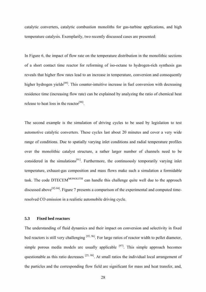
Figure 5: Structure of the computer code DETCHEMMONOLITH and some further modules of
the software package DETCHEMTM [46].
48
Figure 6: Sketch of the catalyst section of a reformer for logistic fuels (iso-octane as
surrogate) with two heat shields (top) and numerically predicted steady-state monolith
temperature at C/O = 1.0 and at flow rates of 2 slpm (top) and 6 slpm (bottom). The symmetry
axis of the monolith is at radial dimension of zero. Taken from Maier et al.[89].
49
Figure 7: Cumulated CO emissions in MVEG driving cycle of an automotive catalytic
converter, simulation versus experiment. The continuously varying raw emissions (inlet, grey
color) shown in the background serve as inlet conditions for the simulation. Taken from
Tischer et al.[93].
50
Figure 8: Example of a direct numerical simulation of a fixed bed reactor with cylindrical
packings showing contours of propane dehydrogenation rate on fresh
catalyst (kmol/m3(solid) · s) (a) and details of mesh (b); taken from Dixon et al.[114].
51
Figure 9: Computed temperature profile (max. 950°C) around a Pt/Rh wire gauze used for
ammonia oxidation (Ostwald process).
52
Figure 10: Snapshots of the computed developing concentration of the product in the wake of
a bubble in a gas-liquid-solid reaction; taken from Raffensberger et al.[122].
53
Figure 11: Numerical simulation of gas-liquid mass transfer in co-current downward Taylor
flow; taken from Kececi et al.[126].
54
Figure 12: Comparison of bubble shape in experiment (left) and simulation (right) for viscous co-current downward Taylor flow in a square mini-channel, taken from Keskin et al.[127].