American Institute of Aeronautics and Astronautics
1
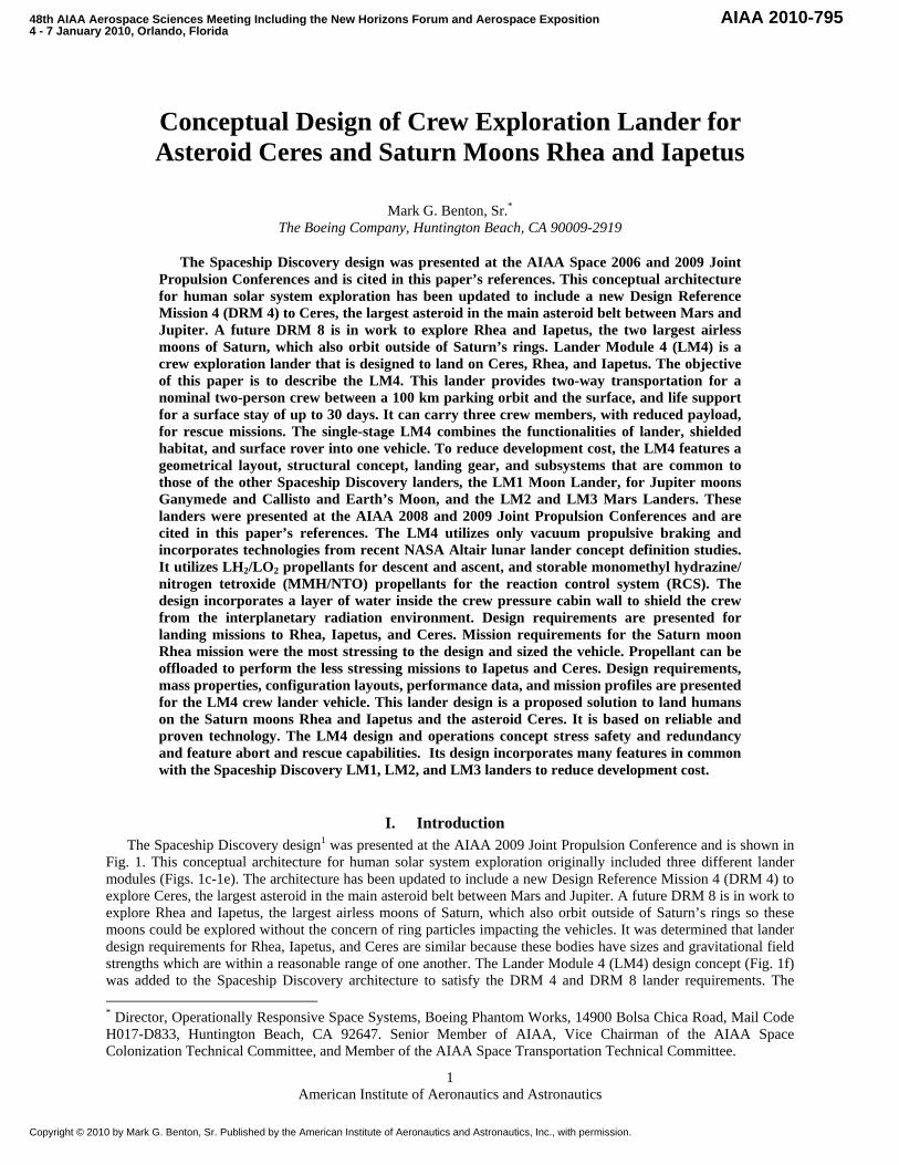
Conceptual Design of Crew Exploration Lander for Asteroid Ceres and Saturn Moons Rhea and Iapetus
Mark G. Benton, Sr.* The Boeing Company, Huntington Beach, CA 90009-2919
The Spaceship Discovery design was presented at the AIAA Space 2006 and 2009 Joint Propulsion Conferences and is cited in this paper’s references. This conceptual architecture for human solar system exploration has been updated to include a new Design Reference Mission 4 (DRM 4) to Ceres, the largest asteroid in the main asteroid belt between Mars and Jupiter. A future DRM 8 is in work to explore Rhea and Iapetus, the two largest airless moons of Saturn, which also orbit outside of Saturn’s rings. Lander Module 4 (LM4) is a crew exploration lander that is designed to land on Ceres, Rhea, and Iapetus. The objective of this paper is to describe the LM4. This lander provides two-way transportation for a nominal two-person crew between a 100 km parking orbit and the surface, and life support for a surface stay of up to 30 days. It can carry three crew members, with reduced payload, for rescue missions. The single-stage LM4 combines the functionalities of lander, shielded habitat, and surface rover into one vehicle. To reduce development cost, the LM4 features a geometrical layout, structural concept, landing gear, and subsystems that are common to those of the other Spaceship Discovery landers, the LM1 Moon Lander, for Jupiter moons Ganymede and Callisto and Earth’s Moon, and the LM2 and LM3 Mars Landers. These landers were presented at the AIAA 2008 and 2009 Joint Propulsion Conferences and are cited in this paper’s references. The LM4 utilizes only vacuum propulsive braking and incorporates technologies from recent NASA Altair lunar lander concept definition studies. It utilizes LH2/LO2 propellants for descent and ascent, and storable monomethyl hydrazine/ nitrogen tetroxide (MMH/NTO) propellants for the reaction control system (RCS). The design incorporates a layer of water inside the crew pressure cabin wall to shield the crew from the interplanetary radiation environment. Design requirements are presented for landing missions to Rhea, Iapetus, and Ceres. Mission requirements for the Saturn moon Rhea mission were the most stressing to the design and sized the vehicle. Propellant can be offloaded to perform the less stressing missions to Iapetus and Ceres. Design requirements, mass properties, configuration layouts, performance data, and mission profiles are presented for the LM4 crew lander vehicle. This lander design is a proposed solution to land humans on the Saturn moons Rhea and Iapetus and the asteroid Ceres. It is based on reliable and proven technology. The LM4 design and operations concept stress safety and redundancy and feature abort and rescue capabilities. Its design incorporates many features in common with the Spaceship Discovery LM1, LM2, and LM3 landers to reduce development cost.
I. Introduction The Spaceship Discovery design1 was presented at the AIAA 2009 Joint Propulsion Conference and is shown in
Fig. 1. This conceptual architecture for human solar system exploration originally included three different lander modules (Figs. 1c-1e). The architecture has been updated to include a new Design Reference Mission 4 (DRM 4) to explore Ceres, the largest asteroid in the main asteroid belt between Mars and Jupiter. A future DRM 8 is in work to explore Rhea and Iapetus, the largest airless moons of Saturn, which also orbit outside of Saturn’s rings so these moons could be explored without the concern of ring particles impacting the vehicles. It was determined that lander design requirements for Rhea, Iapetus, and Ceres are similar because these bodies have sizes and gravitational field strengths which are within a reasonable range of one another. The Lander Module 4 (LM4) design concept (Fig. 1f) was added to the Spaceship Discovery architecture to satisfy the DRM 4 and DRM 8 lander requirements. The * Director, Operationally Responsive Space Systems, Boeing Phantom Works, 14900 Bolsa Chica Road, Mail Code H017-D833, Huntington Beach, CA 92647. Senior Member of AIAA, Vice Chairman of the AIAA Space Colonization Technical Committee, and Member of the AIAA Space Transportation Technical Committee.
48th AIAA Aerospace Sciences Meeting Including the New Horizons Forum and Aerospace Exposition4 - 7 January 2010, Orlando, Florida
American Institute of Aeronautics and Astronautics
2
objective of this paper is to provide design requirements, design details, mission profiles, and flight performance data for the LM4. This lander provides two-way transportation for a nominal two-person crew between orbit and the surface, and provides life support for a surface stay of up to 30 days. The single-stage LM4 is designed for abort to orbit during powered descent. The vehicle is sized to carry three crew members from the surface to orbit for rescue missions. The LM4 lander features a geometrical layout, structural concept, and landing gear that are common to those of the Spaceship Discovery LM1, LM2, and LM3 landers.2,3 The LM4 lander incorporates technologies from recent NASA Altair lunar lander concept definition studies.4,5 Rhea mission requirements were most stressing for the design and sized the vehicle. Propellant can be offloaded to perform missions to Iapetus and Ceres. Design requirements, mission profiles, mass properties, performance data, and configuration layouts are presented for the LM4 crew lander. This design is a proposed solution to land humans on the largest airless moons of Saturn, Rhea and Iapetus, and the largest main belt asteroid Ceres. The LM4 design is based on reliable and proven technology. The vehicle design and operations concept stress safety and redundancy and feature abort and rescue capabilities.
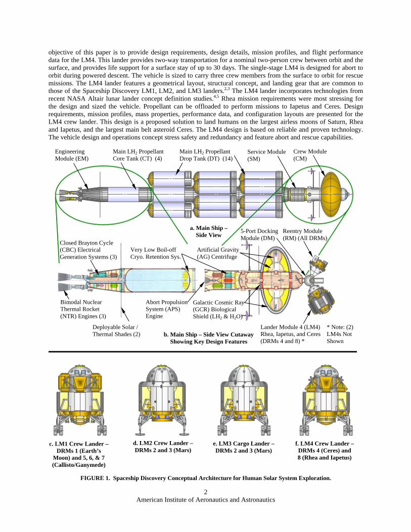
FIGURE 1. Spaceship Discovery Conceptual Architecture for Human Solar System Exploration.
Main LH2 Propellant Drop Tank (DT) (14)
b. Main Ship – Side View Cutaway Showing Key Design Features
a. Main Ship – Side View
Crew Module (CM)
Service Module (SM)
Main LH2 Propellant Core Tank (CT) (4)
Engineering Module (EM)
Closed Brayton Cycle (CBC) Electrical Generation Systems (3)
Very Low Boil-off Cryo. Retention Sys.
Lander Module 4 (LM4) Rhea, Iapetus, and Ceres (DRMs 4 and 8) *
* Note: (2) LM4s Not Shown
Bimodal Nuclear Thermal Rocket (NTR) Engines (3)
Abort Propulsion System (APS) Engine
Deployable Solar / Thermal Shades (2)
5-Port Docking Module (DM)
Reentry Module (RM) (All DRMs)
Galactic Cosmic Ray (GCR) Biological Shield (LH2 & H2O)
Artificial Gravity (AG) Centrifuge
c. LM1 Crew Lander – DRMs 1 (Earth’s
Moon) and 5, 6, & 7 (Callisto/Ganymede)
d. LM2 Crew Lander –DRMs 2 and 3 (Mars)
e. LM3 Cargo Lander –DRMs 2 and 3 (Mars)
f. LM4 Crew Lander –DRMs 4 (Ceres) and 8 (Rhea and Iapetus)
American Institute of Aeronautics and Astronautics
3
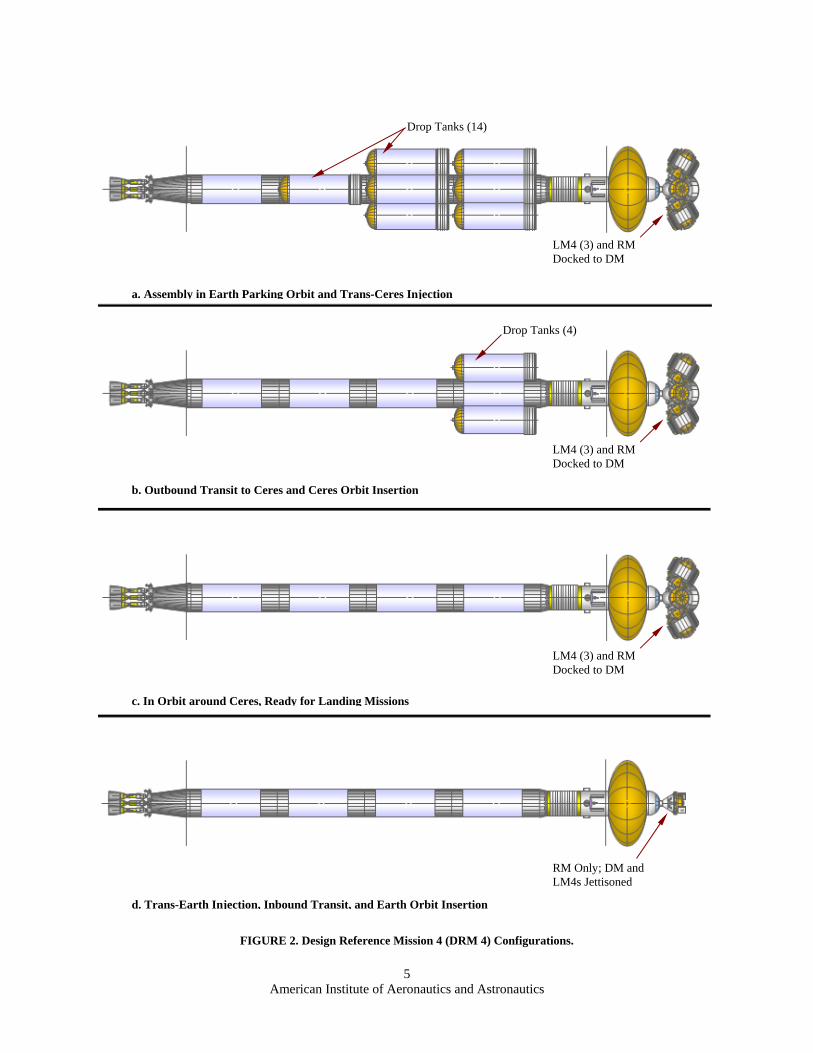
II. Mission Requirements Figures 2a-2d depict the Spaceship Discovery flight vehicle configurations for Design Reference Mission 4
(DRM 4) that will utilize the LM4 Crew Exploration Lander to land on Ceres, the largest asteroid in the main asteroid belt between Mars and Jupiter. A future DRM 8 is in work to explore the two largest airless moons of Saturn, Rhea and Iapetus. These moons orbit outside of Saturn’s rings. DRM 8 will be presented in future work.
A. Design Reference Mission 4 (DRM 4) – Ceres Exploration This DRM examines a minimum-energy, Hohmann Transfer (HT) trajectory from Earth to the asteroid Ceres.
Spaceship Discovery departs earth parking orbit with a cotangential escape maneuver (Trans-Ceres Injection burn, TKI) using the three NTR engines (Note: K is used to denote Ceres in DRM 4; C is used for Callisto in DRMs 5 & 7). There are fourteen DTs on the main ship. Ten are expended during TKI. The main ship, minus DTs, is reusable for this mission. Four crew members are on board. For a nominal mission, the ship arrives at Ceres after a 471 day transit and executes the KOI burn. It is captured into a 185 km altitude circular parking orbit. The ship must then wait for 453 days in Ceres orbit for the correct planetary alignment for departure. Three redundant LM4 landers are carried. The first LM4 lands with two crew members, leaving two crew members in orbit. After a stay of 30 days, the first landing party departs the surface and docks with Discovery. The other two crew members then land and spend 30 days exploring the surface in the second LM4. The third LM4 is always in standby and can be flown by one crew member to rescue either landing party if it became stranded. The Trans-Earth Injection (TEI) burn propels the ship into the inbound 471 day transfer orbit. The nominal mission features a cotangential propulsive capture with an Earth Orbit Insertion (EOI) burn into a circular, 1850 km altitude Earth orbit. The crew and samples return to Earth in the RM. In case of an EOI abort, the return trajectory provides the crew with a non-propulsive opportunity to return to earth in the RM. Hyperbolic entry interface velocity for this contingency is 12.74 km/s.
B. Design Reference Mission 8 (DRM 8) – Rhea and Iapetus Exploration This DRM is reserved for a mission to the Saturn system that is under development. This mission would explore
Rhea and Iapetus, the two largest airless moons of Saturn. These moons orbit outside Saturn’s extensive ring system.
III. Design of LM4 Lunar Crew Exploration Lander Vehicle
A. Design Requirements, Assumptions, and Overview The LM4 crew lander utilizes only vacuum propulsive braking and is designed to explore the airless moons of
Saturn, Rhea and Iapetus, and the largest main belt asteroid Ceres. It provides two-way transportation for a nominal two-person crew between parking orbit and the surface, and also functions as a habitat and rover vehicle. The design incorporates a layer of water in the crew cabin wall to shield the crew from intense radiation environments due to galactic cosmic rays, the solar wind, and belts of charged particles. The LM4 lander normally carries two crew members, with an endurance of 30 days on the surface (including margin) and seven days for ascent and contingencies. It can support three crew members for rescue missions, albeit with reduced endurance. It can achieve orbit with three crew members, three space suits, three emergency life support system units, and a contingency sample (20 kg vs. the normal sample allocation of 125 kg). The LM4 lander extensively utilizes lightweight composite structures to minimize overall system mass and maximize performance. It is envisioned that advanced composite materials used for crew habitation areas will be “dual-mode,” and provide radiation protection shielding as well as structural integrity.6 It utilizes liquid hydrogen and liquid oxygen (LH2/LO2) main propellants and storable monomethyl hydrazine/nitrogen tetroxide (MMH/NTO) reaction control system (RCS) propellants. The LM4 features a 6-axis RCS for attitude control and rendezvous and docking translation maneuvers. The LM4 has functionality and flight profiles similar to the LM1 Crew Lander for the large airless moons Ganymede, Callisto, and Earth’s Moon, but is designed to operate in the much lower gravitational fields of Saturn’s moons Rhea and Iapetus and the asteroid Ceres. Its design incorporates Altair,4,5 Space Shuttle,7, 8 and Apollo Lunar Module 9-12 design data with upgrades for recent advances in materials and subsystems. The LM4 service life is three years (one-year assembly in low-earth orbit plus one-half of the duration of DRMs 4 or 8). The design of LM4 landers is in keeping with the design philosophy for high mission redundancy. Aborts are extensively considered in the design and operations concept. The LM4 is designed for abort-to-orbit (ATO) during all parts of the powered descent. The LM4 landers are not reused during the DRM 4 mission. They are deorbited after completing the docking and crew transfer to the main ship. The future DRM 8 to Saturn’s moons Rhea and Iapetus may, however, take advantage of the single stage feature and refuel and reuse these landers to reduce the number of landers that must be transported to Saturn.
American Institute of Aeronautics and Astronautics
4
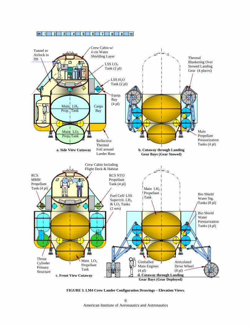
B. Detailed Design Description The overall design of the LM4 is common to the LM1 moon lander and the LM2/LM3 Mars landers, with the
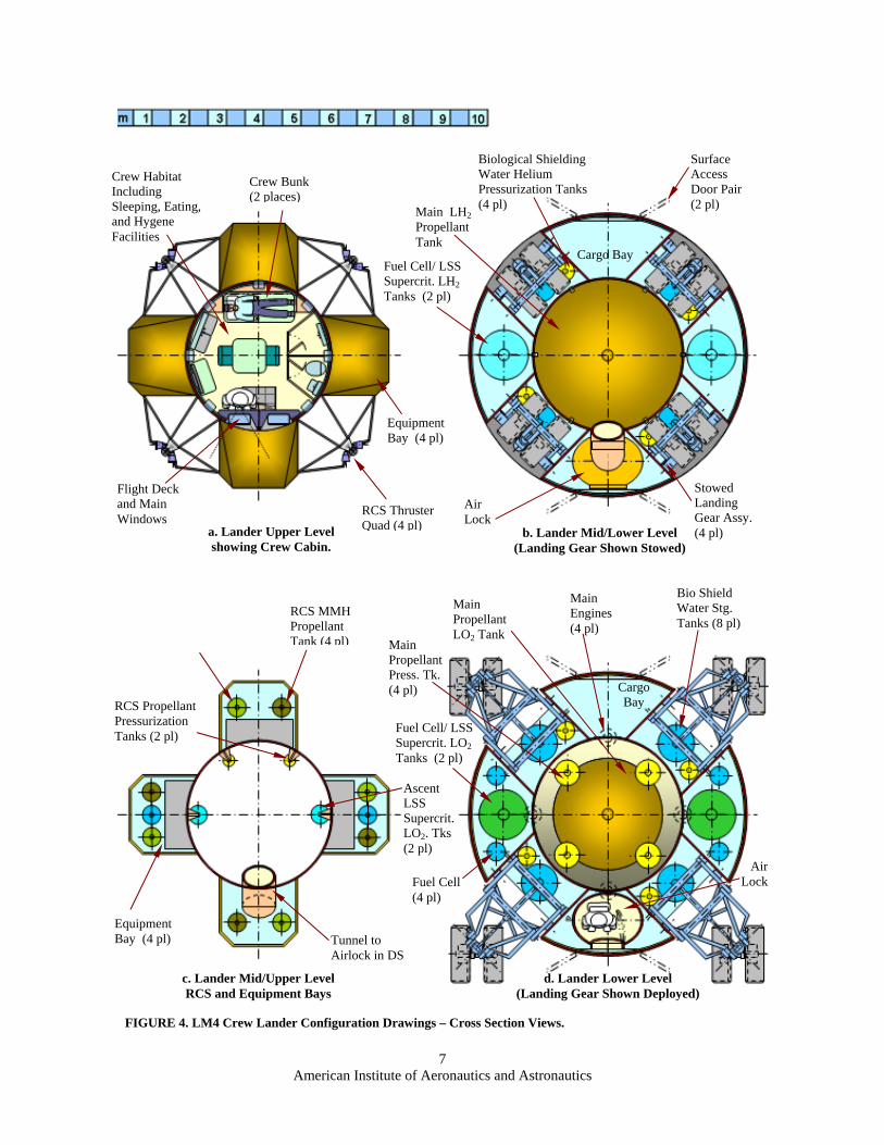
same basic layout that utilizes a central thrust cylinder to efficiently carry loads. The LM4 is a single stage vehicle, whereas LM1, LM2, and LM3 are multi-stage. The crew cabin, airlock, cargo bay, and fuel cell consumables tanks are the same as those used on LM1 and LM2. The landing legs and traversing wheels utilize the same kinematics, geometry, and mechanisms as those used on LM1 and LM3. Structural thicknesses have been reduced to account for reductions in flight loads between Mars and moon missions. Landing gear struts have 0.6 m of shock absorbing stroke and another 0.6 m of adjustability to level the vehicle. The landing gear struts have wheels to enable the LM4 to traverse the surface at the relatively slow pace of 90 m per hour, using 1.0 kW for the drive motors. The LM4 can nominally traverse up to 1.08 km per 24 hour period, assuming 12 hours for stops and crew rest periods each day. Rover wheel motor drive power calculations are scaled from Mars Exploration Rover design data.13 Main propellant, pressurization, fuel cells and their consumables tanks (including breathing oxygen) are the same as those used on LM1. Four gimbaled 5.16 kN main engines, based on the RL-10, are throttleable between 100% and 15% thrust and are spaced at 90-degree intervals at the base of the thrust cylinder. Main engines were sized for maximum thrust and throttling capability for descent maximum/minimum thrust settings and for ascent fixed thrust settings for Rhea, Iapetus, and Ceres missions, for both nominal four-engine cases and “engine-out” two engine cases. In the event of a single engine failure, the corresponding opposite engine would be shut down to balance the thrust. Also, during powered descent, two main engines are shut down in combination with throttling the remaining two engines to start the hover phase, reducing thrust to weight ratio (T/W) from over 3.0 to 1.0. Main engine throttles are set to a constant setting (initial T/W of 3.5) for ascent. The reduced ascent thrust requirements enables single engine-out capability. Main LH2 and LO2 propellant tanks are the same as those used on LM1 and are oversized for the LM4’s DRMs. This will enable the landing of heavier payloads, if required, by carrying additional propellant and up to four additional main engines. Tank and system commonality will also enable most of the LM4 vehicle systems to be flight qualified by the LM1 mission to Earth’s Moon (DRM 1). Descent and surface electrical power is provided by fuel cells, whose design is based on Apollo fuel cells.12 LM4 fuel cells produce up to 4.1 kW peak power. Lander wheel drive motors consume 1 kW, heaters 1 to 2 kW, and a maximum of 1 kW are consumed by the Equipment Cooling and Life Support System (ECLSS), Guidance, Navigation and Control (GN&C) System, communications, and lighting and habitat loads. Reactants are carried to support an average duty cycle of 3 kW. The personnel airlock is accessible by tunnel from the crew cabin. A cargo bay is located on the opposite side of the vehicle as the airlock, with a capacity of 500 kg of cargo for various exploration equipment and science experiments. The crew cabin has 29 m3 of usable inner moldline volume. Eight storage tanks hold the crew cabin shielding water during the powered descent to maintain a lower center of gravity. After landing, the 1,722 kg of water in the tanks is pressurized to fill in a 4.0 cm thick cavity in the crew cabin inner wall. It provides 4 gm/cm2 of radiation shielding, affording the same protection to the crew as that provided by the Spaceship Discovery main ship CM. The water is jettisoned overboard to lighten the vehicle before ascent to orbit. The crew cabin functions as flight deck and habitat for the two person crew. Crew members stand in front of the control console during flight. Two large angled windows provide excellent visibility for approach and landing. The habitat has two bunks, a computer table, a kitchen with dining table and chairs, and hygiene facilities including a toilet, sink, and shower. There are four unpressurized external bays housing the airlock tunnel, GN&C and communications electronics, ECLSS equipment, RCS propellant tanks, and ascent/contingency potable water tanks and batteries. The bays and the central crew cabin are covered with thermal blankets and heavily insulated against the cold environment. The central thrust cylinder, located below the crew cabin, houses RCS helium pressurization tanks and ascent/contingency breathing oxygen tanks. Sixteen 0.77 kN RCS thrusters are arranged in four groups of four. Ascent electrical power is provided by solar arrays and batteries. Solar arrays and radar and communications antennas are attached to the exterior of the vehicle. LM4 configuration layouts are presented in Figs. 3a-3d and 4a-4d, and design data are presented in Tables 1 and 2.
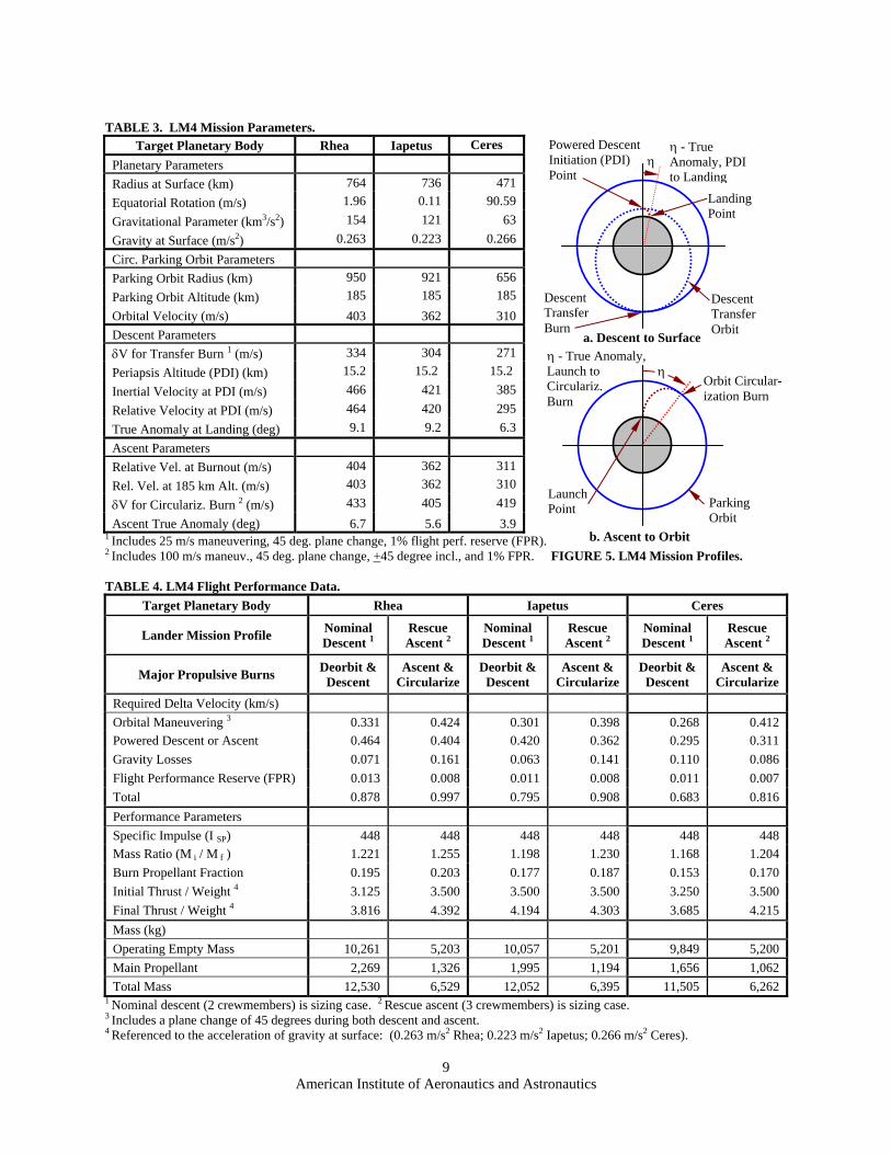
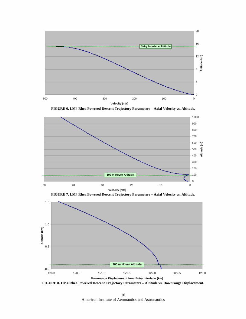
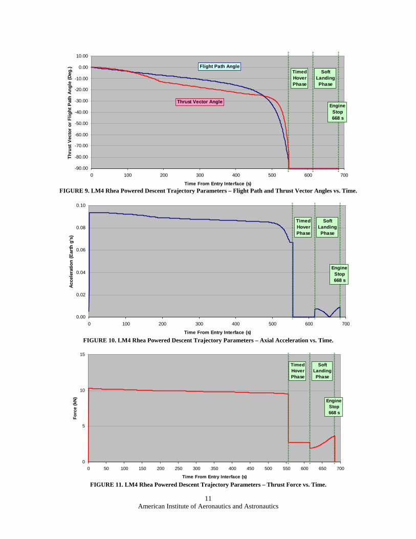
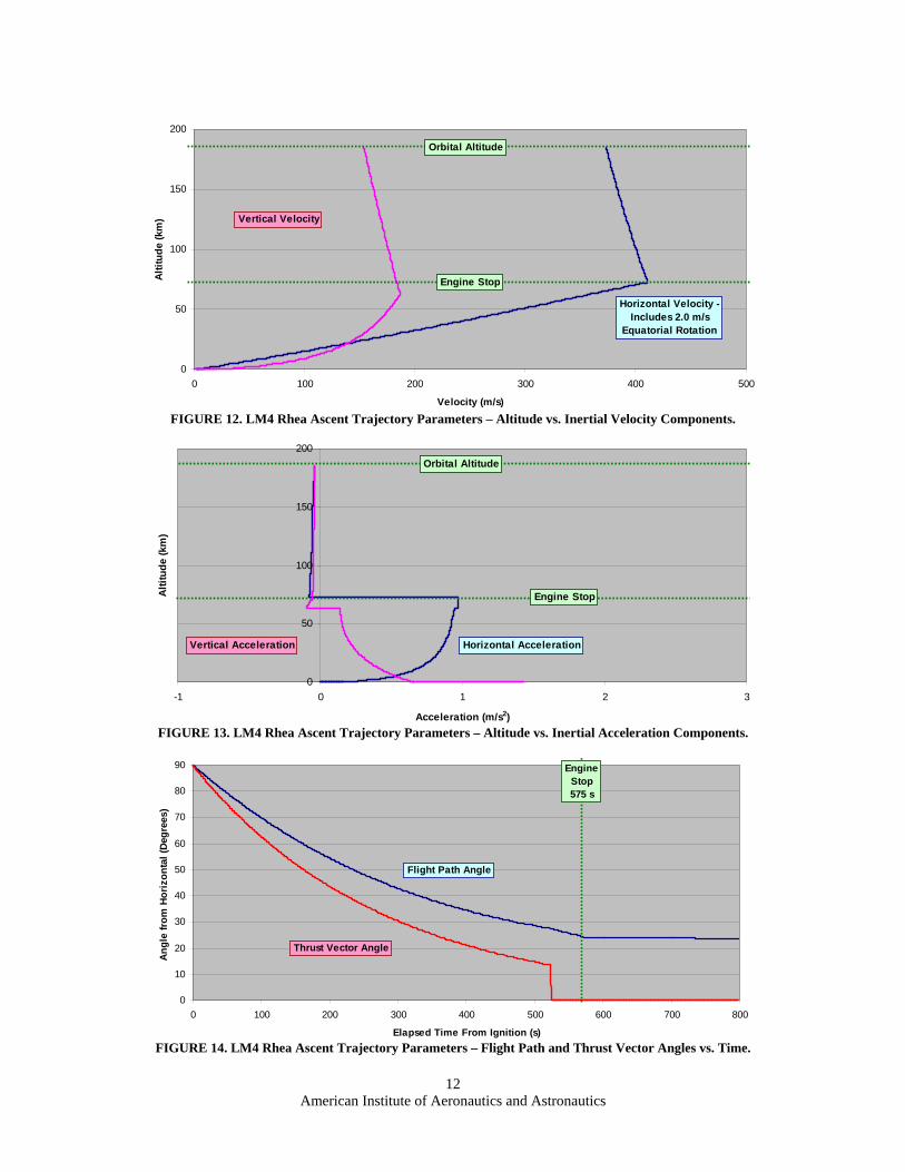
C. Lander Flight Performance Lander ascent and descent flight performance was determined using a 2-D trajectory simulation with a spherical
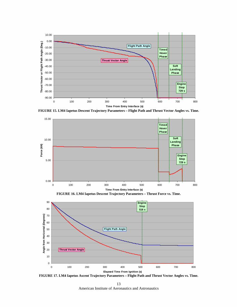
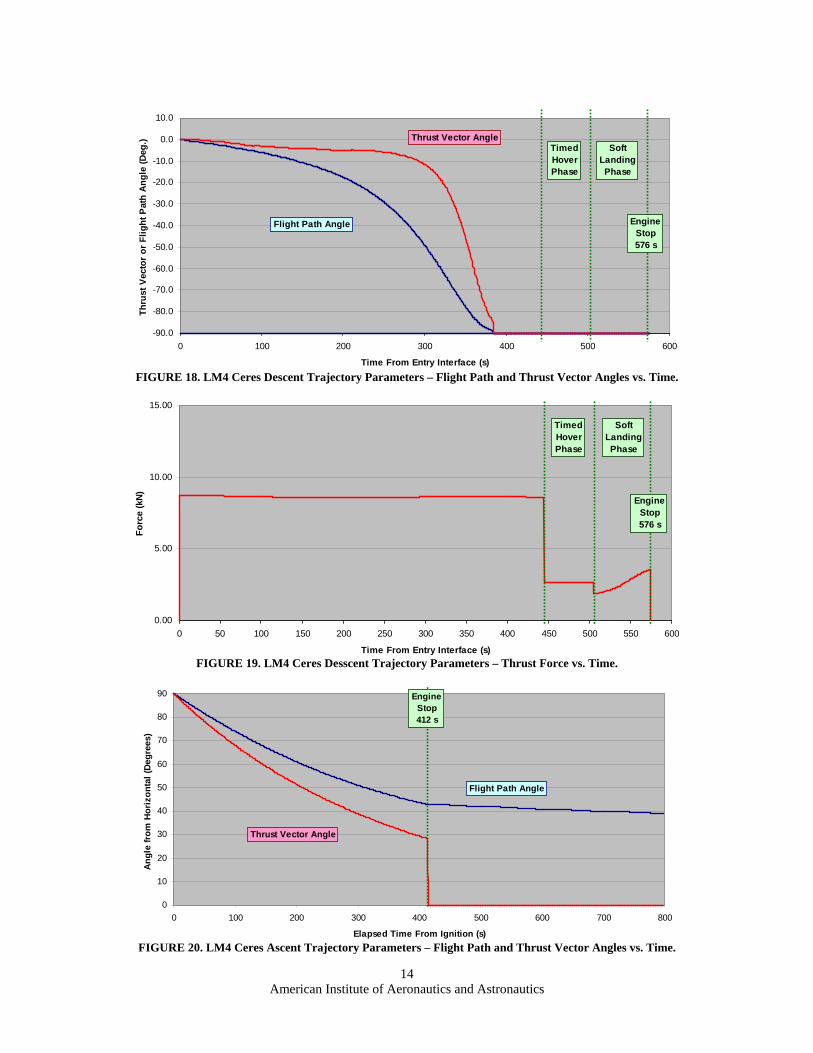
gravitational potential. Performance calculations included 1% flight performance reserve (FPR) on V. Flight performance data for Rhea, Iapetus, and Ceres simulations are presented in Tables 3 and 4. The Rhea mission requirements were most stressing for the design and required the most propellant mass to close the design. The Ceres mission was the least stressing, and the Iapetus mission fell in between the other two missions. Propellant can be offloaded to perform the Iapetus and Ceres missions as shown in Table 4. Performance plots for the Rhea sizing case flight simulations are presented in Figs. 5-14. Flight performance plots for the Iapetus mission are presented in Figs. 15-17. Flight performance plots for the Ceres mission are presented in Figs. 18-20. Some of the Iapetus and Ceres performance plots are very similar to the Rhea case and have been omitted in this paper for brevity.
American Institute of Aeronautics and Astronautics
b. Lander Mid/Lower Level (Landing Gear Shown Stowed)
c. Lander Mid/Upper Level RCS and Equipment Bays
d. Lander Lower Level (Landing Gear Shown Deployed)
Biological Shielding Water Helium Pressurization Tanks (4 pl)
Fuel Cell/ LSS Supercrit. LH2 Tanks (2 pl)
Fuel Cell/ LSS Supercrit. LO2 Tanks (2 pl)
Fuel Cell (4 pl)
RCS Propellant Pressurization Tanks (2 pl)
Equipment Bay (4 pl)
Equipment Bay (4 pl)
Surface Access Door Pair (2 pl)
Main LH2 Propellant Tank
Stowed Landing Gear Assy. (4 pl)
Cargo Bay
Crew Habitat Including Sleeping, Eating, and Hygene Facilities
Flight Deck and Main Windows
Main Propellant LO2 Tank
Main Engines (4 pl)
Air Lock
Ascent LSS Supercrit.LO2. Tks (2 pl)
Bio Shield Water Stg. Tanks (8 pl)
Main Propellant Press. Tk. (4 pl)
American Institute of Aeronautics and Astronautics
8
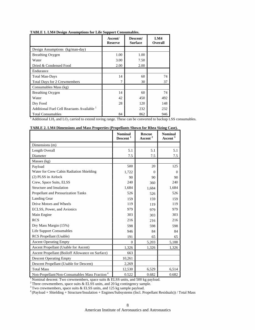
TABLE 1. LM4 Design Assumptions for Life Support Consumables.
Ascent/ Reserve
Descent/ Surface
LM4 Overall
Design Assumptions (kg/man-day)
Breathing Oxygen 1.00 1.00
Water 3.00 7.50
Dried & Condensed Food 2.00 2.00
Endurance
Total Man-Days 14 60 74
Total Days for 2 Crewmembers 7 30 37
Consumables Mass (kg)
Breathing Oxygen 14 60 74
Water 42 450 492
Dry Food 28 120 148
Additional Fuel Cell Reactants Available 1 232 232
Total Consumables 84 862 946 1 Additional LH2 and LO2 carried to extend roving range. These can be converted to backup LSS consumables. TABLE 2. LM4 Dimensions and Mass Properties (Propellants Shown for Rhea Sizing Case).
Nominal Descent 1
Rescue Ascent 2
Nominal Ascent 3
Dimensions (m)
Length Overall 5.1 5.1 5.1
Diameter 7.5 7.5 7.5
Masses (kg)
Payload 500 20 125
Water for Crew Cabin Radiation Shielding 1,722 0 0 (2) PLSS in Airlock 90 90 90 Crew, Space Suits, ELSS 240 360 240
Dry Mass Margin (15%) 598 598 598 Life Support Consumables 946 84 84 RCS Propellant (Usable) 191 65 65 Ascent Operating Empty 0 5,203 5,188 Ascent Propellant (Usable for Ascent) 1,326 1,326 1,326
Ascent Propellant (Boiloff Allowance on Surface) 663
Descent Operating Empty 10,261
Descent Propellant (Usable for Descent) 2,269
Total Mass 12,530 6,529 6,514
Non-Propellant/Non-Consumables Mass Fraction 4 0.522 0.682 0.682 1 Nominal descent: Two crewmembers, space suits & ELSS units, and 500 kg payload. 2 Three crewmembers, space suits & ELSS units, and 20 kg contingency sample. 3 Two crewmembers, space suits & ELSS units, and 125 kg sample payload. 4 (Payload + Shielding + Structure/Insulation + Engines/Subsystems (Incl. Propellant Residuals)) / Total Mass
American Institute of Aeronautics and Astronautics
9
TABLE 3. LM4 Mission Parameters.
Target Planetary Body Rhea Iapetus Ceres
Planetary Parameters
Radius at Surface (km) 764 736 471
Equatorial Rotation (m/s) 1.96 0.11 90.59
Gravitational Parameter (km3/s2) 154 121 63
Gravity at Surface (m/s2) 0.263 0.223 0.266
Circ. Parking Orbit Parameters
Parking Orbit Radius (km) 950 921 656
Parking Orbit Altitude (km) 185 185 185
Orbital Velocity (m/s) 403 362 310
Descent Parameters
V for Transfer Burn 1 (m/s) 334 304 271
Periapsis Altitude (PDI) (km) 15.2 15.2 15.2
Inertial Velocity at PDI (m/s) 466 421 385
Relative Velocity at PDI (m/s) 464 420 295
True Anomaly at Landing (deg) 9.1 9.2 6.3
Ascent Parameters
Relative Vel. at Burnout (m/s) 404 362 311
Rel. Vel. at 185 km Alt. (m/s) 403 362 310
V for Circulariz. Burn 2 (m/s) 433 405 419
Ascent True Anomaly (deg) 6.7 5.6 3.9 1 Includes 25 m/s maneuvering, 45 deg. plane change, 1% flight perf. reserve (FPR). 2 Includes 100 m/s maneuv., 45 deg. plane change, +45 degree incl., and 1% FPR. FIGURE 5. LM4 Mission Profiles. TABLE 4. LM4 Flight Performance Data.
Operating Empty Mass 10,261 5,203 10,057 5,201 9,849 5,200
Main Propellant 2,269 1,326 1,995 1,194 1,656 1,062
Total Mass 12,530 6,529 12,052 6,395 11,505 6,262 1 Nominal descent (2 crewmembers) is sizing case. 2 Rescue ascent (3 crewmembers) is sizing case. 3 Includes a plane change of 45 degrees during both descent and ascent. 4 Referenced to the acceleration of gravity at surface: (0.263 m/s2 Rhea; 0.223 m/s2 Iapetus; 0.266 m/s2 Ceres).
Powered Descent Initiation (PDI) Point
Parking Orbit
Descent Transfer Orbit
Descent Transfer Burn
- True Anomaly, PDI to Landing
- True Anomaly, Launch to Circulariz. Burn
Orbit Circular-ization Burn
Launch Point
Landing Point
a. Descent to Surface
b. Ascent to Orbit
American Institute of Aeronautics and Astronautics
FIGURE 14. LM4 Rhea Ascent Trajectory Parameters – Flight Path and Thrust Vector Angles vs. Time.
0
10
20
30
40
50
60
70
80
90
0 100 200 300 400 500 600 700 800
Elapsed Time From Ignition (s)
An
gle
fro
m H
ori
zon
tal
(Deg
rees
)
Flight Path Angle
Thrust Vector Angle
EngineStop575 s
0
50
100
150
200
-1 0 1 2 3
Acceleration (m/s2)
Alt
itu
de
(km
)
Horizontal AccelerationVertical Acceleration
Engine Stop
Orbital Altitude
0
50
100
150
200
0 100 200 300 400 500
Velocity (m/s)
Alt
itu
de
(km
)
Horizontal Velocity -Includes 2.0 m/s
Equatorial Rotation
Vertical Velocity
Orbital Altitude
Engine Stop
American Institute of Aeronautics and Astronautics
13
FIGURE 15. LM4 Iapetus Descent Trajectory Parameters – Flight Path and Thrust Vector Angles vs. Time.
FIGURE 16. LM4 Iapetus Descent Trajectory Parameters – Thrust Force vs. Time.
FIGURE 17. LM4 Iapetus Ascent Trajectory Parameters – Flight Path and Thrust Vector Angles vs. Time.
0
10
20
30
40
50
60
70
80
90
0 100 200 300 400 500 600 700 800
Elapsed Time From Ignition (s)
An
gle
fro
m H
ori
zon
tal
(Deg
rees
)
Flight Path Angle
Thrust Vector Angle
EngineStop516 s
0.00
5.00
10.00
15.00
0 100 200 300 400 500 600 700 800
Time From Entry Interface (s)
Fo
rce
(kN
)
TimedHoverPhase
SoftLandingPhase
EngineStop729 s
-90.00
-80.00
-70.00
-60.00
-50.00
-40.00
-30.00
-20.00
-10.00
0.00
10.00
0 100 200 300 400 500 600 700 800
Time From Entry Interface (s)
Th
rust
Vec
tor
or
Fli
gh
t P
ath
An
gle
(D
eg.)
TimedHoverPhase
SoftLandingPhase
Flight Path Angle
Thrust Vector Angle
EngineStop729 s
American Institute of Aeronautics and Astronautics
14
FIGURE 18. LM4 Ceres Descent Trajectory Parameters – Flight Path and Thrust Vector Angles vs. Time.
FIGURE 19. LM4 Ceres Desscent Trajectory Parameters – Thrust Force vs. Time.
FIGURE 20. LM4 Ceres Ascent Trajectory Parameters – Flight Path and Thrust Vector Angles vs. Time.
0
10
20
30
40
50
60
70
80
90
0 100 200 300 400 500 600 700 800
Elapsed Time From Ignition (s)
An
gle
fro
m H
ori
zon
tal
(Deg
rees
)
Flight Path Angle
Thrust Vector Angle
EngineStop412 s
0.00
5.00
10.00
15.00
0 50 100 150 200 250 300 350 400 450 500 550 600
Time From Entry Interface (s)
Fo
rce
(kN
)
TimedHoverPhase
SoftLandingPhase
EngineStop576 s
-90.0
-80.0
-70.0
-60.0
-50.0
-40.0
-30.0
-20.0
-10.0
0.0
10.0
0 100 200 300 400 500 600
Time From Entry Interface (s)
Th
rust
Vec
tor
or
Fli
gh
t P
ath
An
gle
(D
eg.)
TimedHoverPhase
SoftLandingPhase
Flight Path Angle
Thrust Vector Angle
EngineStop576 s
American Institute of Aeronautics and Astronautics
15
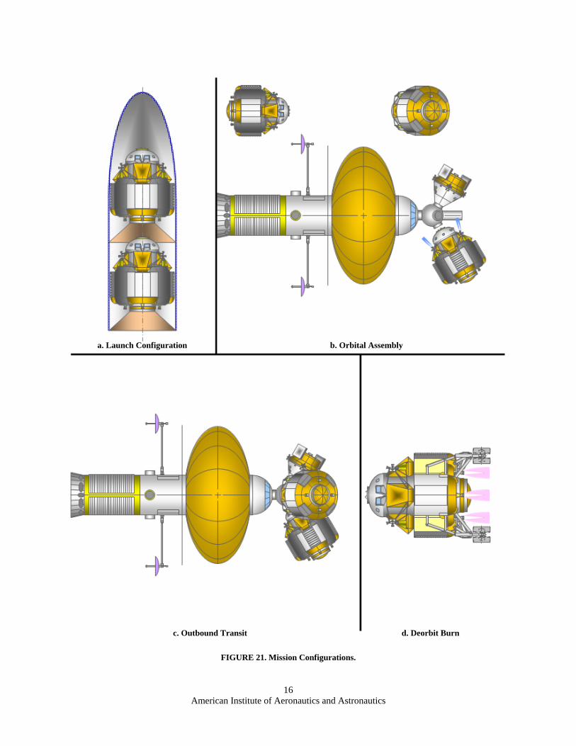
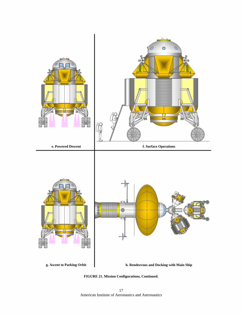
IV. Mission Profiles The key events of the LM4 mission description are presented pictorially in Figs. 21a-21h.
A. Launch from Earth to LEO Assembly Orbit The Spaceship Discovery design is modular and assembled in a circular, 556 km Earth orbit. Subassemblies are
up to 33.0 m length x 8.4 m in diameter, with a maximum mass of 50 metric tons (MT), including fairing, adaptors, and airborne support equipment. Two 11.5 MT LM4 landers can be launched simultaneously as shown in Fig. 21a. Launch vehicles are assumed to be enhanced versions of the current Evolved Expendable Launch Vehicles (EELVs).14, 15 Once in the parking orbit, landers dock to the Spaceship Discovery docking module as shown in Fig. 21b. Vehicle assembly and outfitting will be completed and the main propellant tanks will be topped off. The Ceres mission crew will board, make preparations for the Trans-Ceres Injection burn, and depart Earth orbit for Ceres.
B. Outbound Transit Figure 21c shows three LM4 landers and a Reentry Module docked to the main ship docking module. During
the 15.5 month DRM 4 outbound transit from Earth to Ceres the LM4 landers will be kept in a hibernation mode to conserve power. Periodic automated checkouts of lander systems will be performed. Spaceship Discovery utilizes a Very Low Boil-Off System, with refrigeration plants and space radiator panels, to remove heat from on-board cryogenic propellant and consumables tanks to minimize boil-off. Chilled helium gas is circulated through cryocoolers to remove heat from these tanks. This system will be connected by umbilicals to the three LM4 landers to cool liquid and supercritical H2 and O2 tanks. After insertion into the 185 km altitude circular parking orbit, the landers are powered up and thorough systems checks are performed in preparation for landing.
C. Descent from Parking Orbit to Surface The crew enters the LM4 and the lander undocks from the main ship. Landing gear are deployed and locked.
LM4 landers are designed to operate from parking orbits inclined up to 45 degrees to the equator, and can execute a plane change of up to 45 degrees during descent. This will permit significant flexibility in surface targeting. A deorbit burn is accomplished using the descent engines as shown in Fig. 21d. This maneuver inserts the lander into an elliptical transfer orbit whose periapsis is 15.2 km. The powered descent (PD) is initiated at this point and continues to 100 m above the surface at constant thrust/weight (T/W) of 3.5. PD continues with hovering (T/W = 1.0) at 100 m altitude, with sufficient propellant carried to hover for a maximum of 60 seconds to locate and avoid obstacles. PD concludes with a soft landing (Tables 3 and 4 and Figs. 5a, 6-11, 15, 16, 18, 19 and 21e). In the event of an aborted landing, the engines on the single-stage LM4 will increase thrust to reverse the descent and propel the vehicle into an ascent trajectory that returns it to the 185 km altitude Spaceship Discovery parking orbit. An ATO is available during the entire PD duration. LM4 ATO performance and trajectories will be detailed in future work.
D. Surface Operations The LM4 lander provides a roving habitat for the crew. It provides biological shielding to the crew from the
hazardous radiation environment near Saturn using a combination of advanced “dual-mode” composite materials and a layer of shielding water in the crew cabin. It is designed to traverse up to 30 km during its 30 day surface exploration mission using its powered wheels. It is envisioned that the crew will spend most of their 30 day mission inside the LM4 shielded habitat and only make brief extra vehicular activity (EVA) sorties due to the high radiation environment. Figure 21f shows the LM4 crew lander in its landed configuration. A ladder has been extended from the airlock to permit the crew to access the surface for EVA. LM4 surface operations will be detailed in future work.
E. Ascent to Parking Orbit, Rendezvous, and Docking Before liftoff from the surface, the crew drains the 1,722 kg of shielding water from the LM4 crew cabin shield
tank and jettisons it overboard in order to lighten the vehicle. The single-stage LM4 ascends to orbit as shown if Fig. 21g. The vehicle is designed to ascend to the parking orbit from latitudes of up to + 45 degrees from the equator. The four main engines burn at constant thrust, with an initial thrust-to-weight of 3.5, until sufficient velocity is achieved and they are shut down. The vehicle then coasts up to the parking orbit altitude of 185 km. At this point, the main engines fire again to circularize the orbit and, if required, execute a plane change of up to 45 degrees (Tables 3 and 4 and Figs. 5b, 12-14, 17, and 20). The vehicle then maneuvers in orbit using its main engines and RCS thrusters to rendezvous and dock with the Spaceship Discovery main ship as shown in Fig. 21g. The main ship could also rendezvous and dock with the LM4 in the event of a failure of the LM4 to rendezvous after it has reached parking orbit. The crew transfers to the main ship and the LM4 vehicle is deorbited using its residual propellants.
American Institute of Aeronautics and Astronautics
16
FIGURE 21. Mission Configurations.
a. Launch Configuration b. Orbital Assembly
c. Outbound Transit d. Deorbit Burn
American Institute of Aeronautics and Astronautics
17
FIGURE 21. Mission Configurations, Continued.
e. Powered Descent f. Surface Operations
g. Ascent to Parking Orbit h. Rendezvous and Docking with Main Ship
American Institute of Aeronautics and Astronautics
18
V. Enabling Technologies Continued development of key enabling technologies will be necessary for the implementation of the LM4 crew
lander vehicle. These key enabling technologies are listed below: (1) Reliable launching of 50 MT subassemblies , 33.0 m long x 8.4 meters in diameter, into LEO parking orbits. (2) Lightweight “dual-mode” advanced composite materials for structures that incorporate radiation protection. (3) Highly reliable retention systems for long-term, low-loss storage of cryogenic liquids (LH2 and LO2). (4) Support equipment for long-duration human habitation and surface exploration of airless moons, including
space suits, power generators, life support systems, communications gear, and scientific equipment. This will enable the crew to conduct extensive and detailed scientific explorations of Ceres, Rhea, and Iapetus.
VI. Conclusion The Spaceship Discovery LM4 lander design is a proposed solution to land humans on the largest airless moons
of Saturn, Rhea, and Iapetus, and the largest main belt asteroid, Ceres. The single stage LM4 functions as lander vehicle, habitat, and rover. It provides two-way transportation for a nominal two-person crew between orbit and the surface, life support for a surface stay of up to 30 days, and surface mobility of up to one kilometer per day. It also provides biological radiation shielding for the crew. It provides ascent/contingency life support of up to 7 days. The LM4 design is based on reliable and proven technologies from the Space Shuttle and the Apollo Lunar Module. It incorporates the results of recent NASA Altair lunar lander design studies. To reduce development cost, the LM4 lander features a geometrical layout, structural concept, crew cabin, airlock, and airlock access tunnel, landing gear, tanks, and subsystems that are common to those of the Spaceship Discovery LM1 large airless moon lander and the LM2/LM3 Mars landers. The LM4 lander design and operations concept stresses safety and redundancy and is in keeping with the Spaceship Discovery design philosophy for high mission redundancy: Abort modes and rescue capabilities are extensively considered in the design. The LM4 is designed for abort-to-orbit during all parts of the powered descent. Multiple landers enable multiple exploration landing mission attempts during high value, deep space missions and also enable rescue missions if a landing party were to become stranded on the surface.
References 1 Benton, Sr., M. G., “Spaceship Discovery – NTR Vehicle Architecture for Human Exploration of the Solar System,” AIAA-
2009-5309, 45th AIAA/ASME/SAE/ASEE Joint Propulsion Conference and Exhibit, Denver, CO, 2009. 2 Benton, Sr., M. G., “Crew Exploration Lander for Ganymede, Callisto, and Earth’s Moon - Vehicle System Design,” AIAA-
2008-5179, 45th AIAA/ASME/SAE/ASEE Joint Propulsion Conference and Exhibit, Denver, CO, 2009. 3 Benton, Sr., M. G., “Crew and Cargo Landers for Human Exploration of Mars - Vehicle System Design,” AIAA-2008-5156,
44th AIAA/ASME/SAE/ASEE Joint Propulsion Conference and Exhibit, Hartford, CT, 2008. 4 Benton, Sr., M.G., Donahue, B., Caplin, G., Bienhoff, D., Smith, D.B., and Reiley, K., “Configuration Options to Maximize
Lunar Surface Reuse of Altair Lander Structure and Systems,” AIAA-2009-6405, AIAA Space 2009 Conf., Pasadena, CA, 2009. 5 Benton, Sr., M.G., Caplin, G., Reiley, K., Donahue, B., Messinger, R., and Smith, D.B., “Boeing Design Trades in Support
of the NASA Altair Lunar Lander Concept Definition,” AIAA-2008-7798, AIAA Space 2008 Conference, San Diego, CA, 2008. 6 Sen, S., Schofield, E., Carranza, S., O’Dell, S., “Development of Multifunctional Radiation Shielding Materials for Long
Duration Human Exploration Beyond the Low Earth Orbit,” 58th International Astronautical Congress, Hyderabad, India, (IAC-07-C2.4.02), 2007.
7 Morita, W.H., (ed.), “Space Shuttle System Summary,” Rockwell International Corp., Downey, CA, May, 1980. 8 Goree, J.F., “Shuttle Systems Weight & Performance Monthly Status Report,” (NASA-TM-84748), NASA, May 18, 1982. 9 “Apollo Program Summary Report, App.C – Apollo Spacecraft Weights,” (NASA-TM-X-68725), NASA, 1975, pp. C1-C4. 10 “Apollo 11 Lunar Landing Mission Press Kit,” (NASA Release No. 69-83K), NASA, 1969, pp. 86-107. 11 “Apollo 7 Mission Press Kit,” (NASA Release No. 68-168K), NASA, 1968, pp. 25-30. 12 Heitchue, R.D., (ed.), Space Systems Technology, Reinhold Book Corp., New York, 1968, pp. 224-230. 13 (No author listed) “Mars Exploration Rover: Rover Design, Drive System and Power and Electronic Systems,” Wikipedia
Online Reference, URL: http://en.wikipedia.org/wiki/Mars_Exploration_Rover [cited 22 June 2008]. 14 Covault, C., “Launch Vehicles: Trial by Fire,” Aviation Week and Space Technology, Volume 162, No. 8, February 21,
2005, pp. 48-51. 15 Scott, W.B., “Morphing Rockets: Lockheed Martin's Atlas V Could Evolve to Saturn V-Class Performance,” Aviation
Week and Space Technology, Volume 162, No. 25, June 20, 2005, pp. 62-63.


![Crew Accommodations - Crew Survival Guide - 29JUL2011[1]](https://static.documents.pub/doc/80x56/54f9c32b4a79590b398b479b/crew-accommodations-crew-survival-guide-29jul20111.jpg)


