167
Concrete Mix Design Unit-III
| Date post: | 21-Apr-2017 |
| Category: |
Engineering |
| Upload: | gaurav-h-tandon |
| View: | 76,771 times |
| Download: | 25 times |
Unit-III
SyllabusConcrete Mix Design• Mix Design for compressive strength by I.S. Method, Road Note Method, British method, Mix Design for flexural Strength
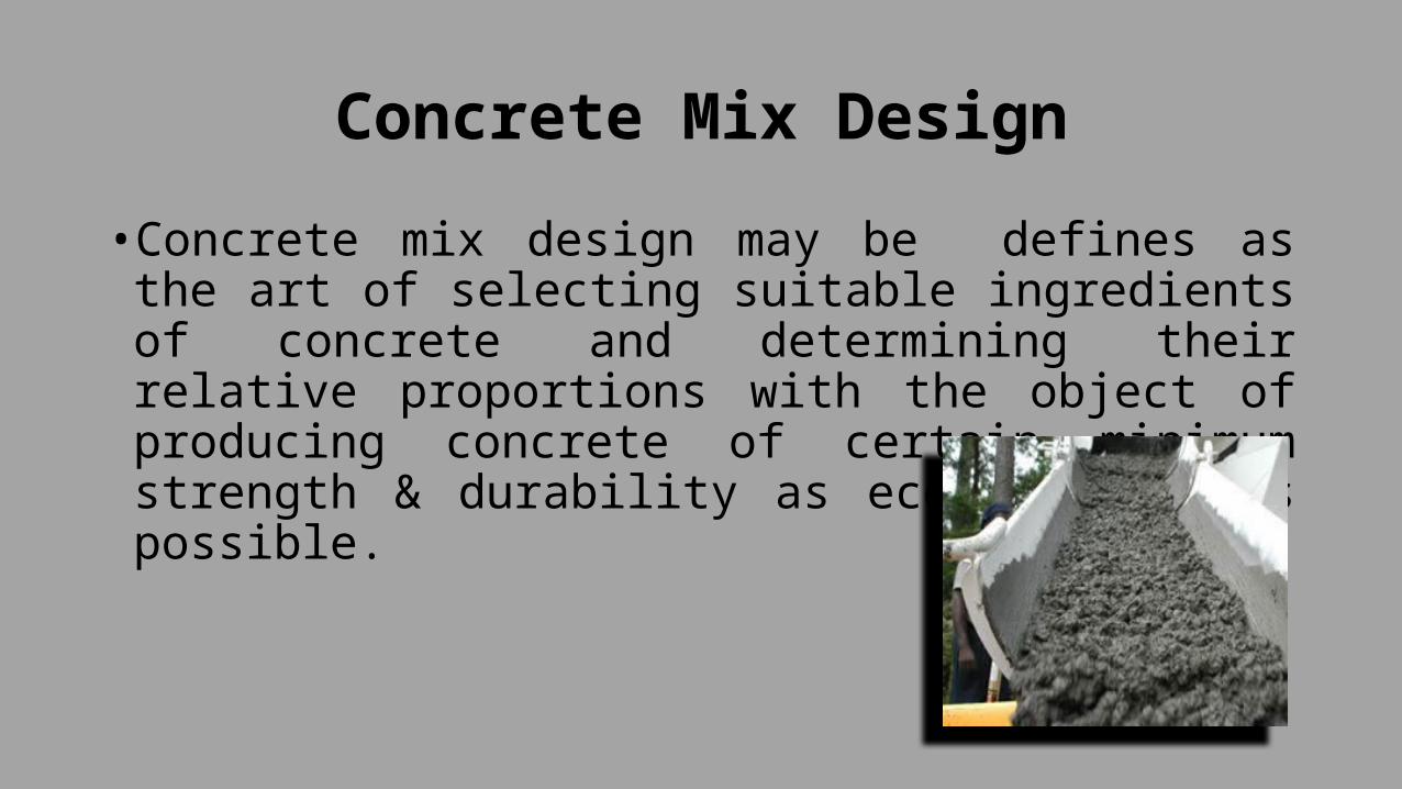
Concrete Mix Design• Concrete mix design may be defines as the art of selecting suitable ingredients of concrete and determining their relative proportions with the object of producing concrete of certain minimum strength & durability as economically as possible.

Objectives of Mix Design• The purpose of concrete mix design is to ensure the
most optimum proportions of the constituent materials to fulfill the requirement of the structure being built. Mix design should ensure following objectives.
• To achieve the designed/ desired workability in the plastic stage
• To achieve the desired minimum strength in the hardened stage
• To achieve the desired durability in the given environment conditions
• To produce concrete as economically as possible.

Basic Considerations• The following point must be considered while designing
concrete mixes• Cost• Specification• Workability• Strength and Durability

Basic ConsiderationsCost• The cost of concrete is made up of• Material Cost• Equipment Cost• Labour Cost• The variation in the cost of materials arises from the fact that
cement is several times costlier than aggregates. So it is natural in mix design to aim at as lean a mix as possible. Therefore, all possible steps should be taken to reduce the cement content of a concrete mixtures without sacrificing the desirable properties of concrete such as strength and durability.

Basic ConsiderationsSpecifications• The following point may be kept in mind while designing
concrete mixes• Minimum Compressive Strength required• Minimum water/ cement ratio• Maximum cement content to avoid shrinkage cracks• Maximum aggregate / cement ratio• Maximum density of concrete in case of gravity dams

Basic Considerations

Basic ConsiderationsWorkability• The following points related to workability shall be kept in mind
while designing concrete mixes.• The consistency of concrete should no more than that necessary
for placing, compacting and finishing.• For concrete mixes required high consistency at the time of
placing, the use of water-reducing and set-retarding admixtures should be used rather than the addition of more water
• Wherever possible, the cohesiveness and finishibility of concrete should be improved by increasing sand/ aggregate ratio than by increasing the proportion of the fine particles in the sand.

Workability

Strength and Durability
Strength and durability• Strength and durability require lower w/c ratio. It is
usually achieved not by increasing the cement content, but by lowering the water at given cement content. Water demand can by lowered by throughout control of the aggregate grading and by using water reducing admixtures.

Strength and Durability

Grade of Concrete• The concrete shall be in grades designated
Group Grade designation Characteristics compressive strength of 150 mm cube at 28 days,
N/mm2Ordinary Concrete M10
M15M20
101520
Standard Concrete M25M30M35M40M45M50M55
25303540455055
High Strength Concrete M60M65M70M75M80
6065707580
What is M 20 ?• M refers to Mix• 20 refers to characteristic compressive strength of 150 mm cube at 28 days in N/mm2
• The minimum Grade of Plain Concrete (PCC) shall be 15 N/mm2
• The minimum grade of reinforced Concrete ( RCC) shall be 20 N/mm2

Nominal Concrete Mixes and
Design mix concreteNominal Mix Concrete• The wide use of concrete as construction materials has led to the use of mixes of fixed proportion, which ensures adequate strength. These mixes are called nominal mixes.
• They offer simplicity and Under normal circumstances, has margin of strength above that specified.
• Nominal mix concrete may be used for concrete of grades M5, M 7.5, M10, M15 and M20.

Nominal Concrete Mixes and
Design mix concrete

Proportions of Ingredients in Nominal Mixes• The proportions of materials for nominal mix shall be in
accordanceGrade Proportions
C: FA: CAM5 1: 5:10
M 7.5 1:4:8M 10 1:3:6M 15 1:2:4M 20 1:1.5:3

Design Mix Concrete• The concrete mix produced under quality control
keeping in view the strength, durability, and workability is called the design Mix.
• Others factors like compaction equipment's available, curing method adopted, type of cement, quality of fine and coarse aggregate etc. have to be kept in mind before arriving at the mix proportion.
• The design mix or controlled mix is being used more and more in variety of important structures, because of better strength, reduced variability, leaner mixed with consequent economy, as well as greater assurance of the resultant quality.

Design Mix Concrete

Factors Influencing Choice of Mix Design
• According to IS 456:2000 and IS 1343:1980 the important influencing the design of concrete mix are
• Grade of Concrete• Type of Cement• Maximum nominal Size of Aggregate• Grading of Combined aggregate• Maximum Water/ Cement Ratio• Workability• Durability• Quality Control.

Factors Influencing Choice of Mix Design
Grade of Concrete• The grade of concrete gives characteristic compressive strength of concrete. It is one of the important factor influencing the mix design
• The grade M 20 denotes characteristic compressive strength fck of 20 N/mm2. Depending upon the degree of control available at site, the concrete mix is to be designed for a target mean compressive strength (fck) applying suitable standard deviation.

Factors Influencing Choice of Mix Design

Factors Influencing Choice of Mix Design
Type of Cement• The rate of development of strength of concrete is influenced by the type of cement.
• The higher the strength of cement used in concrete, lesser will be the cement content. The use of 43 grade and 53 grade of cement, gives saving in cement consumption as much as 15 % and 25 % respectively, as compared to 33 grade of cement. For concrete of grade M25 it is advisable to use 43 and 53 grade of cement.

Types of Cement

Factors Influencing Choice of Mix Design
Maximum Nominal Size of Aggregates• The maximum size of C.A is determined by sieve analysis. It is
designated by the sieve size higher than larger size on which 15 % or more of the aggregate is retained. The maximum nominal size of C.A. should not be more than one-forth of minimum thickness of the member.
• For heavily reinforced concrete members as in the case of ribs of main beams, the nominal maximum size of the aggregate should usually be restricted to sum less than the minimum clear distance between the main bars or 5 mm less the minimum cover to the reinforcement, whoever is smaller.
• The workability of concrete increases with an increase in the maximum size of aggregate. But the smaller size of aggregates provide larger surface area for bonding with the mortar matrix which gives higher strength.
Factors Influencing Choice of Mix Design
Grading of Combined Aggregates• The relative proportions of the fine and coarse aggregate in a concrete mix is one of the important factors affecting the strength of concrete.
• For dense concrete, it is essential that the fine and coarse aggregate be well graded. In the case when the aggregate available from natural sources do not confirm to the specified grading, the proportioning of two or more aggregate become essential

Grading of Combined Aggregates

Factors Influencing Choice of Mix Design
Maximum Water/ Cement Ratio• Abram’s water/Cement ratio states that for any given
condition of test, the strength of a workability concrete mix is dependent only on water/cement ratio. The lower the water/Cement ratio, the greater is the compressive strength
Workability• Workability of fresh concrete determines the case with
which a concrete mixture can be mixed, transported, placed, compacted and finished without harmful segregation and bleeding.

Factors Influencing Choice of Mix Design
Durability• Durability require low water/Cement ratio. It is usually achieved not by increasing the cement content, but by lowering the water demand at a given cement content.
• Water demand can be lowered by through control of the aggregate grading and by using water reducing admixtures

Method of Concrete Mix Design• Some of the commonly used mix design methods are• I.S. Method• A.C.I method• Road Note 4 method ( U.K. Method)• IRC 44 method• Arbitrary method• Maximum Density method• Fineness modulus method• Surface area Method• Nix design for high strength Concrete• Mix design for pumpable Concrete• DOE (British) Mix design method

IS Method of Mix Design• The Bureau of Indian Standards, recommended a set of procedure for
design of concrete mix. The procedure is based on the research work carried out at national laboratories.
• Data for mix design• The following basic data are required to be specified for design a
concrete mix• Characteristic Compressive strength only a few specified proportions of
test results are expected to fall of concrete at 28 days (fck)• Degree of workability desired• Limitation on water/Cement Ratio with the minimum cement to ensure
adequate durability• Type and maximum size of aggregate to be used.• Standard deviations of compressive strength of concrete.

IS Method of Mix Design• Target Strength for Mix Design• The target average compressive strength (fck) of concrete at 28 days is
given by
• Fck= f ck + t.sWhere,• Fck= target average compressive strength at 28 days• F ck= characteristics compressive strength at 28 days• s= Standard deviation• t= a stastical value, depending upon the accepted proportion of low
results and the number of tests.

IS Method of Mix Design• According to Is 456: 2000 and IS 1343:1980 te characteristic strength is defined as the value below which not more than 5 percent of results are expected to fall. In such cases the above equation reduced to
• Fck= fck + 1.65 s• The value of standard deviation is obtained from the table

IS Method of Mix Design

IS Method of Mix DesignStep-IISelection of Water –Cement Ratio• Since different cements and aggregates of different
maximum sizes, grading, surface texture shape and other characteristics may produce concrete of different compressive strength for the same free water cement ratio, the relationship between strength and free water cement ratio should preferable be established for the material actually to be used. In the absence of such data, the preliminary free water-cement ratio corresponding to the target strength at 28 days may be selected from the relationship shown below

IS Method of Mix Design

IS Method of Mix Design• Alternatively, the preliminary free water cement ratio by mass corresponding to the average strength may be selected from the relationship shown below using the curve corresponding to the 28 days cement strength to be used for the purpose. However, this will need 28 days for testing of cement.

IS Method of Mix Design

IS Method of Mix Design• The free water-cement ratio thus selected should be checked against limiting water-cement ratio for the requirements of durability as per table 5.4 and the lower of the two values should be adopted.

IS Method of Mix Design

IS Method of Mix DesignStep 3 Estimation of Air Content• Approximate amount of entrapped air to be expected in
normal concrete is given in table 9.6Nominal Maximum Size of
AggregatesEntrapped Air, as percentage
of volume of concrete10 3 %20 2 %40 1 %

IS Method of Mix DesignSelection of Water Content and fine to total aggregate ratio• For the desired workability the quantity of mixing water
per unit volume of concrete and the ratio of fine aggregate (sand) to total aggregate by absolute volume are to be estimated from table below as applicable. Depending upon the nominal maximum size and type of aggregate.

IS Method of Mix Design• Approximate Sand and water Content per Cubic Metre
of Concrete for Grades up to M 35 W/C = 0.6 Workability= 0.8 C.F
Nominal Maximum size of aggregate (mm)
Water Content per cubic metre of concrete (kg)
Sand as percentage of
total aggregate by absolute
volume10 208 4020 186 3540 165 30

IS Method of Mix Design• Approximate Sand and Water Content per cubic metre
of concrete for grades above M 35 W/C = 0.35 Workability= 0.8 C.F.
Nominal Maximum size of Aggregates
Water Content per cubic metre of concrete (kg)
Sand as percentage total aggregate by absolute volume of (%)
10 200 2820 180 25

IS Method of Mix Design• Adjustment of values in water content and sand
percentage for other conditionsChange in Condition
Adjustment Required
Water Content Percentage sand in total aggregate
For sand confirming to grading Zones I , III and IV
0 + 1.5 percent for zone I-1.5 percent for zone III-3.0 for zone IV
Increase or decrease in values of compacting factor by 0.1
± 3 % 0
Each 0.05 increase or decrease in free water cement ratio
0 ± 1 %
-15 kg/m 3 -7 %
For rounded aggregates

Calculation of Cement Content• The cement content per unit volume of concrete may be calculated from the free water-cement ratio obtained in step- 2, and the quantity of water per unit volume of concrete obtained in step-4
• The cement content so obtained should be checked against the minimum cement content for the requirement of durability as per table 5 IS 456:2000 and the greater of the two value is adopted.

Step -6 Calculation of Aggregate Content
• With the quantities of water and cement per unit volume of concrete and the ratio of fine to total aggregate already determined, the total aggregate content per unit volume of concrete may be calculated from the following equations
• V= [ W + C + 1 x fa ] x 1 for fine aggregate …………………………1
Sc p Sfa 1000AndV = [ W + C + 1 x Ca ] x 1 for coarse aggregate …………..2 Sc (1-p) Sca 1000

Step -6 Calculation of Aggregate ContentWhere, • V= Absolute volume of fresh concrete (m3)• W= Mass of Water (kg) per m3 of concrete• C= Mass of Cement (Kg) per m3 of concrete• Sc= Specific gravity of cement say 3.15• P= ratio of fine aggregate to total aggregate by absolute volume• Fa and Ca = Total masses of fine aggregate and coarse aggregate
(kg) / m3 of concrete mass respectively• Sfa, Sca= Specific gravities of saturated surface dry fine aggregate
and coarse aggregate respectively• Normally Sfa= 2.6 and Sca= 2.7

Trial Mixes• The Calculated mix proportions shall be checked by means of trial batches. The quantity of material should be sufficient for at least three 150 mm size cube concrete specimens

Example• Using I.S Method design a concrete mix for reinforced concrete structure for the following requirement.
• Design data• Characteristic compressive strength= 20 N/mm 2
• Maximum size of aggregates= 20 mm (angular)• Degree of workability= 0.9 CF• Degree of quality Control= Good• Type of exposure= Mild

Example• Test data for Material• Cement used= Ordinary Portland cement of grade 43 with 28 days
strength 51 N/mm2
• SG= 3.15• Bulk Density = 1450 kg/m3
• Aggregate Fine Aggregate Coarse Aggregate
• SG 2.66 2.75• Bulk Density 1700 1800• Water absorption 1 0.5• Free Moisture 2 Nil

Example Step-I Target Mean Strength• Fck= fck + ts• fck= 20 N/mm2
• T= 1.65• S= 4 from table 9.5 for M 20• Therefore • Fck= 20 + 1.65 x 4• = 26.6 N/mm2 (Mpa)

ExampleStep-II• Selection of Water Cement Ratio• From the fig the free water cement ratio required for the
target mean strength of 26.6 N/ mm2 is 0.5• From fig, for 28 days strength of cement 51 N/mm2, for
curve D the free water cement ratio is 0.52• From table the maximum free water cement ratio for mild
exposure is 0.55• Hence the free water cement ratio is taken as the minimum
of above three values i.e. w/c = 0.5

ExampleStep –III • Estimation of Air Content• For maximum Size of aggregate of 20 mm, the air
content is taken as 2 %

ExampleStep-4 Selection of water and Sand Content• From table 9.7 for 20 mm nominal maximum size
aggregate and sand confirming to grading zone –II water content per cubic metre of concrete = 186 kg and sand content as percentage of total aggregate by absolute volume= 35 %
• Water= 186 kg/m3 of concrete• Sand= 35 % of total aggregate by absolute volume

Example• For change in values in water cement ratio, compaction
factor and sand belonging to zone III the following adjustments required.
Change in Condition Water Content
Percentage Sand in total aggregate
For Decrease in water cement ratio (0.6-0.5) that is 0.10.1 x 1 = 2.00.05
0 -2.0
For increase in compacting factor (0.9 -0.8) = 0.10.1 x 3 = 30.1
+ 3 0
For Sand conforming to Zone III 0 -1.5+3 -3.5

Example• Required Water Content = 186 + ( 186 x 3 / 100)• = 186 + 5.58• = 191.6 lit /m3
= required sand content as percentage of total aggregate by absolute volume= 35 – 3.5= 31.5 %
ExampleDetermination of Cement Content• Water Cement ratio= 0.5• Water = 191.6 lit= 191.6 kg• Therefore W/c = 0.5 • 191.6 = 0.5• C• C=383.4 kg/m3
• = 383kg/m3 > 300 kg / m3 therefore O.K.

ExampleDetermination of fine and coarse Aggregates• Consider volume of Concrete= 1 m3
• But entrapped air in wet concrete = 2 %• Therefore volume of fresh concrete= 1 – 2 100 1- 0.02V= 0.98 m3

Example• With the quantities of water and cement per unit volume of
concrete and the ratio of fine to total aggregate already determined, the total aggregate content per unit volume of concrete may be calculated from the following equations
• V= [ W + C + 1 x fa ] x 1 for fine aggregate ………………1
Sc p Sfa 10000.98 = [ 191.6 + 383 + 1 + fa ] x 1 3.15 0.315 2.66 1000980 = 313.187 + 1.19 fafa= 558.75 kg mass of F.A

ExampleAndV = [ W + C + 1 x Ca ] x 1 for coarse aggregate …………..2 Sc (1-p) Sca 10000.98 = [ 191.6 + 383 x 1 x Ca ] x 1 3.15 (1-0.315) 2.75 1000980 = 313.187 + 0.5308 Ca
Ca= 1256.24 kg mass of C.A

ExampleWater Cement F.A C.A191.6 li 383 kg 558.75 kg 1256.24 kg0.5 1 1.46 3.28
Water Cement F.A C.A383 = 0.264 m 3
1450558.75 = 0.328 m 3
1700
1256.24 = 0.698 m 3
18000.5 1.0 1.242 2.644

ExampleWater Cement F.A C.A25 li 50 kg 73 kg 164 kg
Example• Design a Concrete mix for M 25 grade as per IS 10262
for the following data:• Characteristic Compressive Strength in the field at 28
days 25 N/mm2
• Maximum Size of Aggregate= 20 mm• Degree of Workability 0.9 CF• Degree of Quality Control= Good• Type of Exposure = Moderate

ExampleTest data for Material• Cement Used : Ordinary Portland Cement of Grade 33 satisfying the requirement of IS:
269-1989• Specific Gravity of Cement: 3.15• Specific Gravity; • Coarse Aggregate=2.65• Fine Aggregate= 2.6• Water absorption• Coarse Aggregate 0.6 %• Fine aggregate= 1.2 %• Free moisture• Coarse aggregate Nil• Fine aggregate 2 %• CA conform to table 2 of IS 383-1970 FA is natural river Sand Confirming to Zone I of
Table 383-1970

ExampleStep-I• Target mean Strength of Concrete• Fck= fck + ts• fck= 25 N/mm2
• T= 1.65 from table 9.4• S= 4.0 from table 9.5 for M 25 grade of concrete• Fck= 25 + 1.65 x 4• = 31.6 N/mm2

ExampleStep-2 • Selection of Water-Cement Ratio• From fig 9.1 the free water cement ratio required for the target
mean strength of 31.6 N/mm 2 is 0.44• Now, from table 5.4 the maximum free water cement ratio for
moderate exposure is 0.5• Hence, the free water cement ratio is taken as the minimum of
above two value i.e
• W= 0.44 C
ExampleStep III Estimation of air Content• For maximum Size of Aggregate of 20 mm, the air
content is taken as 2.0 %

ExampleStep-4 • Selection of Water and Sand Content• From table 9.7 for 20 mm nominal maximum size
aggregates and sand confirming to grading Zone-II, water content per cubic metre of concrete = 186 kg and sand content as percentage of total aggregate by absolute volume = 35 % i.e.
• Water = 186 kg/m3
• Sand = 35 % of total aggregate by absolute Volume.

Example• For Change in values in water-Cement ratio, compaction
factor and sand belonging to zone I the following adjustments are required.

Change in Condition Adjustment RequiredWater Content Percentage Sand in
total Aggregate(i) For Decrease in Water-Cement ratio (0.6 – 0.44) that
is 0.16 Therefore 0.16 x 1 = 3.2
0.05
0 -3.2
(ii) For Increase in Compacting factor (0.9 -0.8)= 0.1
Therefore 0.1 x 3 = 3.0 0.1
+3 0
(iii) For Sand Conforming to Zone-I of table 4 of IS 383-1970
0 +1.5

Example• Required water Content = 186 + ( 186 x 3 ) 100= 191.6 lit / m3
Required Sand Content as Percentage of Total aggregate by absoluter Volume p= 35 – 1.7= 33.3 %

ExampleStep- V Determination of Cement Content• Water Cement Ratio = 0.44• Water = 191.6 lit = 191.6 kg• Therefore,• W= 0.44 C191.6 = 0.44 CC= 435.45 kg/m3 > 300 kg /m3
This cement content is adequate for ‘Moderate Exposure’ condition, according to table 5 IS 456-2000)

ExampleDetermination of fine and Coarse content:• Consider volume of concrete = 1 m3
But, entrapped air in wet concrete= 2 %Therefore, absolute volume of fresh concrete= 1 – 2 100= 1 – 0.02V= 0.98 m3
Therefore,
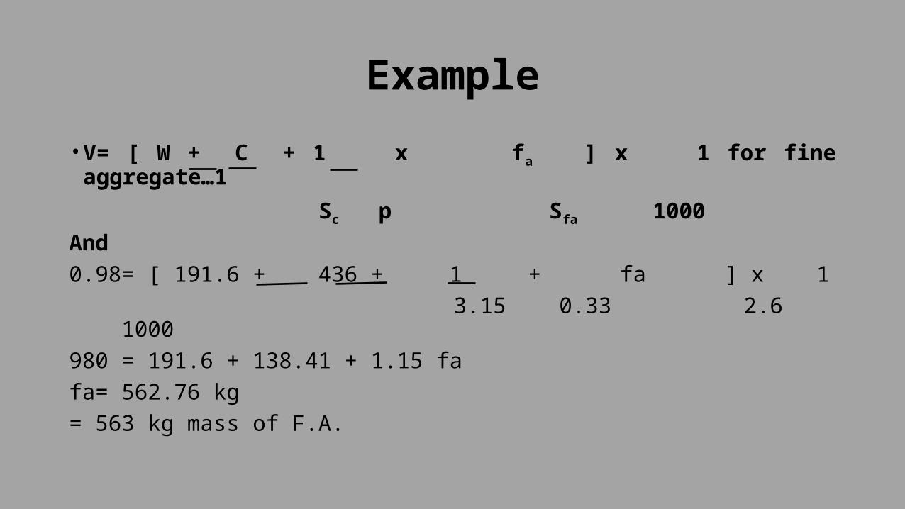
Example• V= [ W + C + 1 x fa ] x 1 for fine aggregate…1
Sc p Sfa 1000And0.98= [ 191.6 + 436 + 1 + fa ] x 1 3.15 0.33 2.6 1000980 = 191.6 + 138.41 + 1.15 fafa= 562.76 kg= 563 kg mass of F.A.

ExampleSimilarly,V = [ W + C + 1 x Ca ] x 1 for coarse aggregate……..2 Sc (1-p) Sca 1000• 0.98 = [ 191.6 + 436 x 1 x Ca ] x 1 3.15 (1-0.333) 2.65 1000980 = 191.6 + 138.41 + 0.5657 CaCa= 1149 kg/m3 mass of C.A.

Example• Mix Proportions (By Mass)
Water Cement F.A. C.A191.6 li 436 kg 563 kg 1149 kg0.44 1 1.29 2.64

ExampleWater Cement F.A. C.A22 li 50 kg 64.5 kg 132 kg

ExampleStep 8 Adjustment for water absorption and free surface moisture in F.A. and C.A• For water Cement ratio of 0.44 quantity of water required = 22 lit• C.A absorbs 0.6 % of water by mass• Therefore extra quantity of water to be added • 0.6 x 132 = 0.792 lit (+) 100F.A contains 2 % free moisture by massQuantity of water to be deducted= 2 x 64.5 = 1.29 (-) 100Actual quantity of water to be added= 22 + 0.792 – 1.29= 21.5 lit

Example• Actual quantity of sand (FA) required after allowing for
mass of free water • = 64.5 + 1.29 = 65.79 kg• Actual quantity of C.A required• = 132 - 0.792• = 131.21 kg
Water Cement F.A. C.A21.50 li 50 kg 65.79 kg 131.21 kg

Example• Design a concrete mix from the following data by I.S. method• Target mean Strength= 35 N/mm2
• Maximum Size of Aggregate = 20 mm• W/C ratio = 0.43• Water required per m3 of concrete= 190 kg• Sand as percentage of total aggregate by absolute Volume = 35 %• Entrapped air in concrete= 2 %• Sp gravity of Cement= 3.15• Sp gravity of fine aggregate= 2.6• Sp gravity of Coarse aggregate.= 2.7

ExampleStep-I Target mean Strength• Fck=35 N/mm2
Step-II Selection of Water-Cement Ratio:• W/C ratio = 0.43Step-III Estimation of air Content• Entrapped air = 2 % Step-IV • Selection of water and sand Content• Quantity of water per m3 of concrete = 190 kg• Sand Content = 35 % of total aggregate by absolute Volume

ExampleStep-V• Cement Content• Water-Cement Ratio = 0.43• Water = 190 kg• W = 0.43 c190 = 0.43 CC= 441 .86 kg/m3

ExampleDetermination of F.A and C.A Content• Consider Volume of Concrete = 1 m 3
• But, entrapped air = 2 %• Therefore Absolute Volume of press Concrete• V= 1 – 2 100V= 0.98 m3

Example• V= [ W + C + 1 x fa ] x 1 for fine aggregate ………………1
Sc p Sfa 10000.98 = [ 190 + 442 + 1 + fa ] x 1 3.15 0.35 2.6 1000 0.98 = [ 190 + 140.32 + 1.098 fa] x 1 1000fa= 591.69 kg/m3
fa= 592 kg/m3 Mass of FA

ExampleSimilarly,V = [ W + C + 1 x Ca ] x 1 for coarse aggregate……..2 Sc (1-p) Sca 1000• 0.98 = [ 190 + 442 x 1 x Ca ] x 1• 3.14 (1-0.35) 2.7 1000• 980 = 190 + 140.32 + 0.569 Ca• Ca= 1142 kg/m3 Mass of CA

Example• Mix Proportion (by mass)
• Quantity for 1 bag of Cement
Water Cement F.A C.A190 442 592 11420.43 1 1.34 2.58
Water Cement F.A C.A21.5 50 67 129

The ACI Method of Mix Design• In the USA the method suggested by ACI is widely used. It has the advantages of simplicity in that it applies equally well, and with more or less identical procedure to rounded or angular aggregate, to normal or lightweight aggregate and to air-entrained or non-air-entrained concretes.
• The ACI method is based on the fact that for a given size of well graded aggregates water content is largely independent of mix proportions, i.e. Water content regardless of variation in water/cement ratio and cement content.

The ACI Method of Mix Design• This method assumes that the optimum ratio of the bulk volume of coarse aggregates and on the grading of fineness aggregates regardless of shape of particles. This method also assumes that even after complete compaction is done, a definite percentage of air remains which is inversely proportional to the maximum size of aggregate.

The ACI Method of Mix Design• The steps by steps operation in the ACI method areStep-1 Data to be collected• Fineness modulus of FA• Unit weight of dry CA• Specific gravity of FA and CA saturated surface dry
condition.• Specific gravity of Cement• Absorptions characteristics of both CA and FA
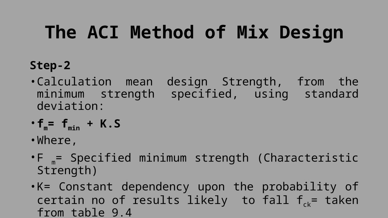
The ACI Method of Mix DesignStep-2• Calculation mean design Strength, from the minimum
strength specified, using standard deviation:• fm= fmin + K.S• Where,• F m= Specified minimum strength (Characteristic
Strength)• K= Constant dependency upon the probability of certain
no of results likely to fall fck= taken from table 9.4• S= Standard Deviation from table 9.5

IS Method of Mix Design

The ACI Method of Mix DesignStep-3 Estimation of Water-Cement Ratio• Water Cement ratio is estimated from table 9.10 for the
mean design Strength.

The ACI Method of Mix DesignAverage Compressive Strength at 28 days
Effective Water-Cement Ratio (By Mass)
Non-Air Entrained Concrete
Air-entrained Concrete
45 0.38 -40 0.43 -35 0.48 0.430 0.55 0.4625 0.62 0.5320 0.7 0.6115 0.8 0.71

The ACI Method of Mix Design• The water Cement ratio obtained from Strength point of view is to be checked against maximum W/C Ratio given for special exposure condition given in table 9.11 and minimum of the two is to be adopted.

The ACI Method of Mix Design• Requirement of ACI for W/C Ratio and Strength for
Special Exposure Condition

Exposure Condition Maximum W/C ratio, normal density aggregate concrete
Minimum Design Strength, low Density aggregate Concrete, MPA
Concrete Intended to be Watertight(a)Exposed to fresh Water(b)Exposed to brackish or
sea Water
0.50.45
2530
Concrete Exposed to freezing and Thawing in a moist Condition:
(a) Kerbs, gutters, guard rails or thin sections
0.45 30
Other elements 0.5 25In presence of de-icing chemicals
0.45 30
For corrosion protection of reinforced concrete exposed to de-icing salts, brackish water, sea water or spray from the sources.
0.4 30

The ACI Method of Mix Design• Decide maximum size of aggregate to be Used.
Generally RCC work 20 mm and Pre-stressed Concrete 10 mm Size are Used
• Decide Workability in terms of slump for the type of job in hand. General guidance can be taken from table 9.12.
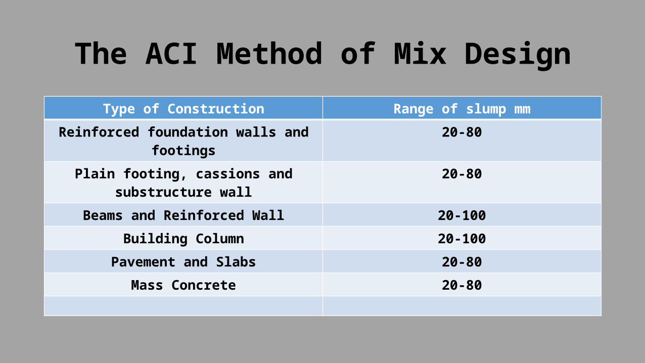
The ACI Method of Mix DesignType of Construction Range of slump mm
Reinforced foundation walls and footings
20-80
Plain footing, cassions and substructure wall
20-80
Beams and Reinforced Wall 20-100Building Column 20-100
Pavement and Slabs 20-80Mass Concrete 20-80

The ACI Method of Mix DesignStep-4 Minimum Water Content and entrapped air content:• Decide maximum size of aggregate to be used.
Generally for RCC work 20 mm and for pre-stressed concrete 10 mm size are used.
• Decide workability in terms of slump for the type of job in hand. Recommended value of slump for various types of construction as given in table 9.12

The ACI Method of Mix DesignStep-5 Cement Content• Cement Content is computed by dividing the water
content by the water/ Cement RatioStep-6• Bulk Volume of Dry Rodded Coarse Aggregate per Unit
Volume of Concrete• Table 9.13 for a decided value of slump and maximum
size of aggregate, decide the mixing water content and entrapped air content.
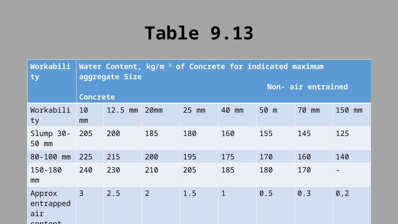
Table 9.13Workability
Water Content, kg/m 3 of Concrete for indicated maximum aggregate Size Non- air entrained Concrete
Workability 10 mm
12.5 mm
20mm 25 mm 40 mm 50 m 70 mm 150 mm
Slump 30-50 mm
205 200 185 180 160 155 145 125
80-100 mm
225 215 200 195 175 170 160 140
150-180 mm
240 230 210 205 185 180 170 -
Approx entrapped air content
3 2.5 2 1.5 1 0.5 0.3 0,2

Table 9.13Workability
Water Content, kg/m 3 of Concrete for indicated maximum aggregate Size Air entrained Concrete
Workability 10 mm
12.5 mm
20mm 25 mm 40 mm 50 m 70 mm 150 mm
Slump 30-50 mm
180 175 165 160 145 140 135 120
80-100 mm 200 190 180 175 160 155 150 135150-180 mm
215 205 190 185 170 165 160 -

Table 9.13Workability
Water Content, kg/m 3 of Concrete for indicated maximum aggregate Size Air entrained Concrete
Workability
Water Content, kg/m 3 of Concrete for indicated maximum aggregate Size Air entrained Concrete10 mm 12.5
mm20mm 25 mm 40 mm 50 m 70 mm 150 mm
Slump 30-50 mm
180 175 165 160 145 140 135 120
80-100 mm
200 190 180 175 160 155 150 135
150-180 mm
215 205 190 185 170 165 160 -
Recommended air
Content
Mild Exposu
re
4.5 4 3.5 3.0 2.5 2.0 1.5 1.0
Moderate
Exposure
6.0 5.5 5.0 4.5 4.5 4.0 3.5 3.0
Extreme
Exposure
7.5 7.0 6.0 6.0 5.5 5.0 4.5 4.0
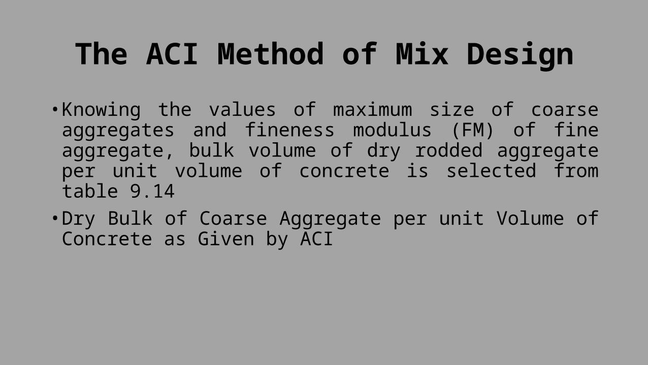
The ACI Method of Mix Design• Knowing the values of maximum size of coarse
aggregates and fineness modulus (FM) of fine aggregate, bulk volume of dry rodded aggregate per unit volume of concrete is selected from table 9.14
• Dry Bulk of Coarse Aggregate per unit Volume of Concrete as Given by ACI

Maximum Size of Aggregate
Bulk Volume of Dry Rodded Coarse Aggregate per unit volume of concrete for fineness modulus of sand
FM 2.4 2.6 2.8 3.010 0.5 0.48 0.46 0.44
12.5 0.59 0.57 0.55 0.5320 0.66 0.64 0.62 0.625 0.71 0.69 0.67 0.65
40 0.75 0.73 0.71 0.6950 0.78 0.76 0.74 0.7270 0.82 0.8 0.78 0.76
150 0.87 0.85 0.83 0.81(a)The value given will produce a mix that is suitable for reinforced concrete
construction. For less workable concrete the value may be increased by 10 percent for workable concrete such as pumpable concrete the value may be
reduced by upto 10 percent(b)From the minimum strength specified estimate the average design strength
either by using coefficient of variation(c)Find the water/cement ratio from the table 9.14

The ACI Method of Mix DesignStep-7• The weight of CA per cubic metre of Concrete is Calculated by multiplying the bulk Volume with bulk density of CA
Step-8 Estimate of Density of fresh Concrete• Knowing the maximum Size of Coarse Aggregates, the density of fresh Concrete is estimated as
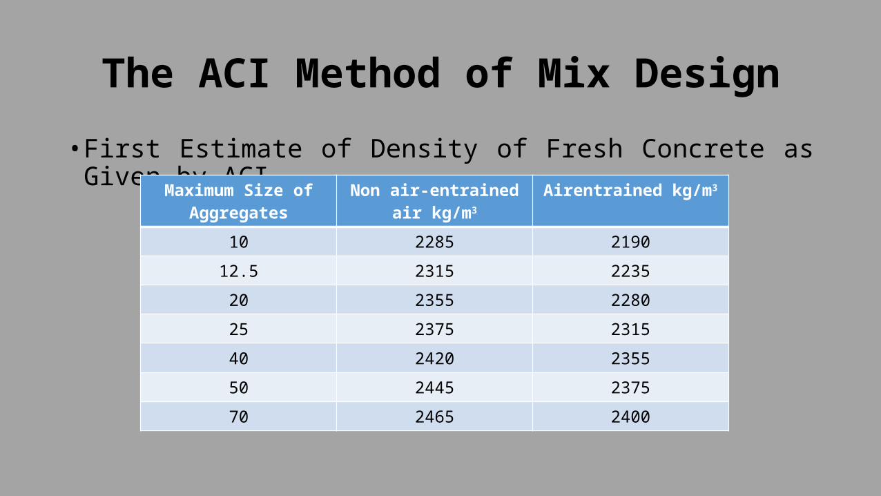
The ACI Method of Mix Design• First Estimate of Density of Fresh Concrete as Given by
ACI Maximum Size of Aggregates
Non air-entrained air kg/m3
Airentrained kg/m3
10 2285 219012.5 2315 223520 2355 228025 2375 231540 2420 235550 2445 237570 2465 2400

The ACI Method of Mix DesignStep-9• Absolute volumes of ingredients per cubic metre of concrete are
obtained by knowing the specific gravity of cement, water CA and FAStep- 10• Trial mix proportions are calculated and adjustments for field conditions
like free moisture and water absorption by aggregates are made.Step-11• A trial mix is then made to study the properties of concrete in respect
of workability, cohesiveness, finishing quality and 28 days compressive strength. The proportion of CA and FA may be changed to get desired properties.

Example-IDesign a Concrete mix Using ACI method for a multi-Storied building for the following data• 28 days characteristic Compressive Strength= 30 Mpa• Type of Cement Available= Ordinary Portland Cement• Desired Slump= 80-100 mm• Maximum Size of aggregate = 20 mm• Standard Deviation from past Records = 4.5 Mpa• Specific Gravities for FA= 2.65• Specific Gravity for CA= 2.7• For Cement= 3.15• Bulk density of CA= 1600 kg/m3
• Fineness modulus of FA= 2.8• CA absorbed 1 % moisture and sand• Contains 1.5 % free surface moisture• Assume any other data

Example-ISolutionStep-I• Mean Design Strength• fm= fmin + K.S• = 30 + 1.65 x 4.5• = 37.425 Mpa• From table 9.4• Assume 5 % of test results are expected fall• K= 1.65

Example-IStep-II• Estimation of Water-Cement Ratio• From table 9.1 for mean design strength of 37.425 Mpa,
the estimated W/C ratio is 0.45• From table 9.11, for exposure condition “concrete
intended to be watertight and exposed to fresh water”, the maximum
• w/C ratio is 0.5• Hence adopt a water cement ratio of 0.45

The ACI Method of Mix DesignAverage Compressive Strength at 28 days
Effective Water-Cement Ratio (By Mass)
Non-Air Entrained Concrete
Air-entrained Concrete
45 0.38 -40 0.43 -35 0.48 0.430 0.55 0.4625 0.62 0.5320 0.7 0.6115 0.8 0.71

Exposure Condition Maximum W/C ratio, normal density aggregate concrete
Minimum Design Strength, low Density aggregate Concrete, MPA
Concrete Intended to be Watertight(a)Exposed to fresh Water(b)Exposed to brackish or
sea Water
0.50.45
2530
Concrete Exposed to freezing and Thawing in a moist Condition:
(a) Kerbs, gutters, guard rails or thin sections
0.45 30
Other elements 0.5 25In presence of de-icing chemicals
0.45 30
For corrosion protection of reinforced concrete exposed to de-icing salts, brackish water, sea water or spray from the sources.
0.4 30

Example-I• Mixing water content and entrapped air content• Maximum size of aggregates = 20 mm• Desired Slump= 80-100• Therefore from table 9.13• Mixing water Content = 200 kg/m3 of Concrete• Entrapped air Content = 2 %

Table 9.13Workability
Water Content, kg/m 3 of Concrete for indicated maximum aggregate Size Non- air entrained Concrete
Workability
10 mm
12.5 mm
20mm 25 mm 40 mm 50 m 70 mm 150 mm
Slump 30-50 mm
205 200 185 180 160 155 145 125
80-100 mm
225 215 200 195 175 170 160 140
150-180 mm
240 230 210 205 185 180 170 -
Approx entrapped air content
3 2.5 2 1.5 1 0.5 0.3 0,2

Table 9.13Workability
Water Content, kg/m 3 of Concrete for indicated maximum aggregate Size Air entrained Concrete
Workability 10 mm
12.5 mm
20mm 25 mm 40 mm 50 m 70 mm 150 mm
Slump 30-50 mm
180 175 165 160 145 140 135 120
80-100 mm 200 190 180 175 160 155 150 135150-180 mm
215 205 190 185 170 165 160 -

Table 9.13Recommended air
Content
Mild Exposu
re
4.5 4 3.5 3.0 2.5 2.0 1.5 1.0
Moderate
Exposure
6.0 5.5 5.0 4.5 4.5 4.0 3.5 3.0
Extreme
Exposure
7.5 7.0 6.0 6.0 5.5 5.0 4.5 4.0

Example-IStep-4• Cement Content• W/C ratio = 0.45• 200 = 0.45 CC= 445 kg/m3
Water = 200 kg/m3 of concrete

Example-IStep-5• Bulk Volume of Dry Rodded CA:• Maximum Size of CA= 20 mm• Fineness modulus of FA= 2.8• Therefore table 9.14• The bulk volume of dry rodded CA is 0.62 per unit
volume of Concrete

Maximum Size of Aggregate
Bulk Volume of Dry Rodded Coarse Aggregate per unit volume of concrete for fineness modulus of sand
FM 2.4 2.6 2.8 3.010 0.5 0.48 0.46 0.44
12.5 0.59 0.57 0.55 0.5320 0.66 0.64 0.62 0.625 0.71 0.69 0.67 0.65
40 0.75 0.73 0.71 0.6950 0.78 0.76 0.74 0.7270 0.82 0.8 0.78 0.76
150 0.87 0.85 0.83 0.81(a)The value given will produce a mix that is suitable for reinforced concrete
construction. For less workable concrete the value may be increased by 10 percent for workable concrete such as pumpable concrete the value may be
reduced by upto 10 percent(b)From the minimum strength specified estimate the average design strength
either by using coefficient of variation(c)Find the water/cement ratio from the table 9.14

Example-IStep-6• Weight of CA = 0.62 x 1600• = 992 kg/m3
• Therefore density of CA is 1600 kg/m3

Example-IStep-7• Dry density of fresh Concrete• For maximum Size of CA = 200 mm and non air
entrained Concrete,• From table 9.15 dry density of fresh Concrete= 2355 kg/m3

Example-IStep-8• Mass of all the known Ingredient of Concrete• Mass of water= 200 kg/m3
• Mass of Cement= 445 kg/m3
• Mass of CA= 992 kg/m3
• Mass of FA = 2355-[ 200 + 445 + 992]= 718 kg/m3

Example-ISr.no Ingredient Mass, kg/m3 Absolute Volume
m31 Cement 445 445 =
0.141 m3
3.15 x 10002 Water 200 200= 0.2 m3
1 x 10003 CA 992 992 = 0.367
m3
2.7 x 10004 Entrapped Air 2 % 2 x 1 = 0.02 %
100
Total Absolute Volume
0.728 m3
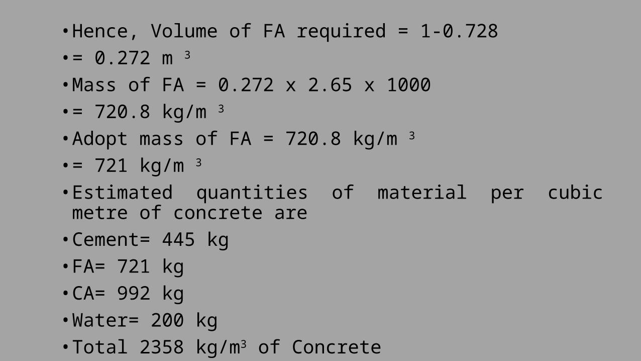
• Hence, Volume of FA required = 1-0.728• = 0.272 m 3
• Mass of FA = 0.272 x 2.65 x 1000• = 720.8 kg/m 3
• Adopt mass of FA = 720.8 kg/m 3
• = 721 kg/m 3
• Estimated quantities of material per cubic metre of concrete are
• Cement= 445 kg• FA= 721 kg• CA= 992 kg• Water= 200 kg• Total 2358 kg/m3 of Concrete
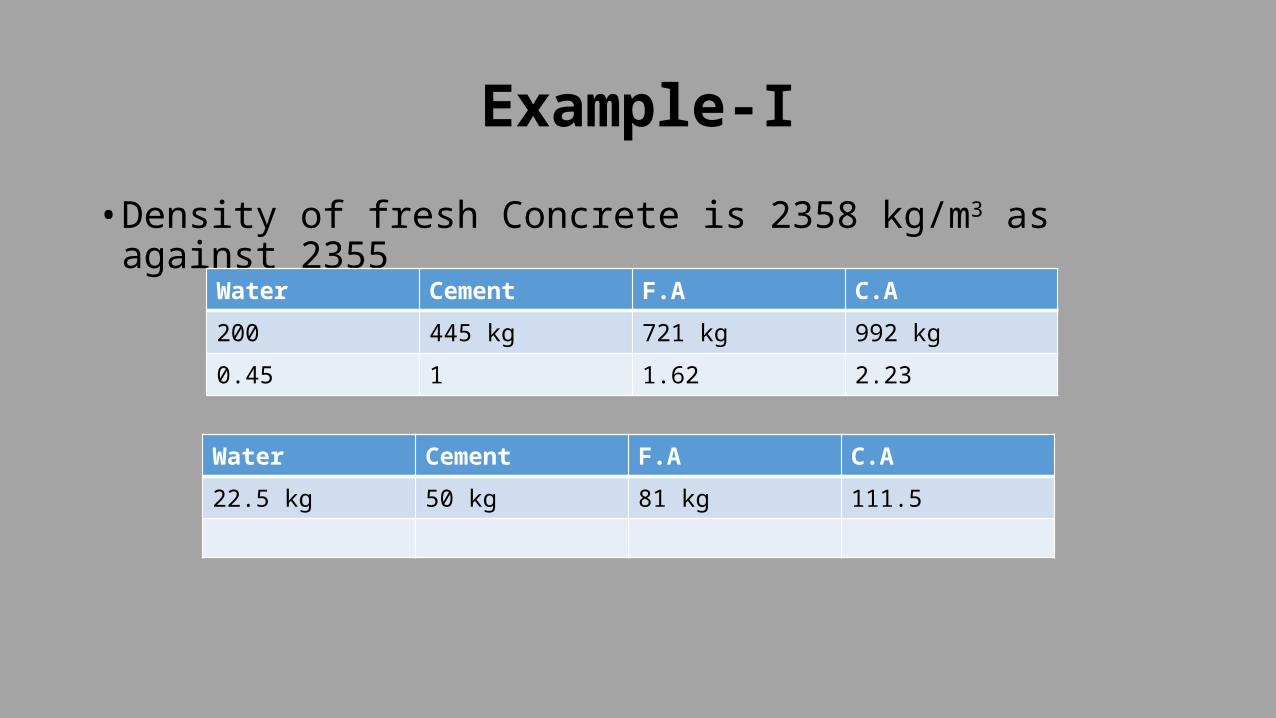
Example-I• Density of fresh Concrete is 2358 kg/m3 as against 2355
Water Cement F.A C.A200 445 kg 721 kg 992 kg0.45 1 1.62 2.23
Water Cement F.A C.A22.5 kg 50 kg 81 kg 111.5

Example-I• Adjustment for water absorption and free surface moisture• F.A Contains 1.5 % free surface moisture• Total surface moisture of FA = 1.5 x 721 100 = 10.82 kg (-)Mass of FA in field condition = 721 + 10.82 = 731.83 kg/m3
Say 732 kg/m3CA absorbs 1 % of moisture,Quantity of water absorbed by CA = 1 x 992 100= 9.92 kg (+)Therefore mass of CA in field Condition = 992 – 9.92= 982 kg/m3
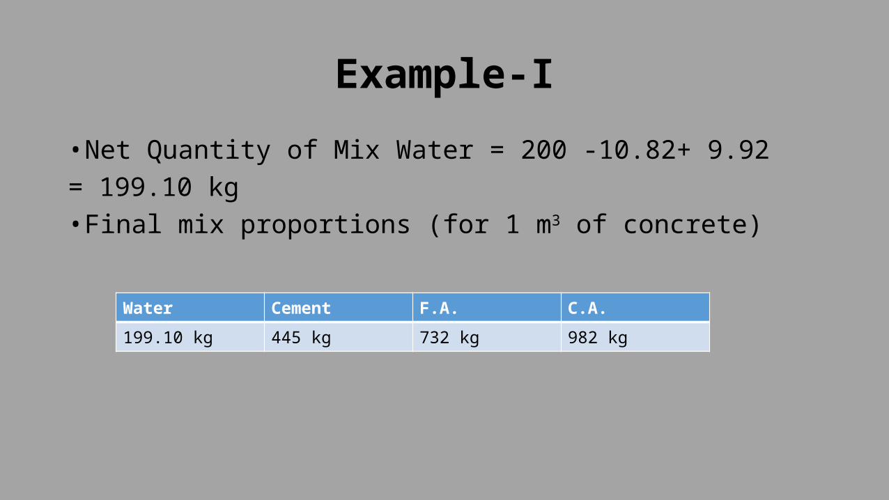
Example-I• Net Quantity of Mix Water = 200 -10.82+ 9.92= 199.10 kg• Final mix proportions (for 1 m3 of concrete)
Water Cement F.A. C.A.199.10 kg 445 kg 732 kg 982 kg

The British Method• The traditional British method has been replaced by the department of the
environment for normal mixes, known as DOE(British) mix design method.• The following steps are Involved in DOE Method Step-I• Find the target mean strength from the specified Characteristic Strength• ft= fck + k.S• Where,• ft= target mean strength• fck= characteristic Strength• S= Standard Deviation• K= risk factor or probability factor
CONCRETE MIX DESIGN

Step-IIDetermination of free water cement ratio• From the given type of cement and aggregate, obtain
the compressive strength of concrete corresponding to free w/c ratio of 0.5 Type of Cement
Type of Coarse Aggregate
3 7 28 91
Ordinary or Sulphate Resisting Cement
UncrushedCrushed
2227
3036
4249
4956
Rapid Hardening Portland Cement
UncrushedCrushed
2934
3743
4855
5461
CONCRETE MIX DESIGN

• Now adopt the pair of data i.e. compressive strength read from table 9.16 and w/c ratio mark point ‘P’. Through this point draw a dotted curve parallel to neighbouring curve. Using this new curve we read the w/c ratio as against target strength ft calculated in step 1
• Check this w/c ratio for durability considerations and adopt the lower value
Minimum grade
30 35 40 45 50
Maximum w/c ratio
0.65 0.6 0.55 0.5 0.45
Maximum cement content
275 300 325 350 400
CONCRETE MIX DESIGN

Fig.1 Relation between compressive strength and free water cement ratio mark a point corresponding to strength f1, at water cement ratio 0.5. draw a curve parallel to the nearest curve, through this pointUsing the new curve, Read off ( abscissa) the water cement ratio corresponding to the target mean strength (ordinate) Free water-cement
ratioCONCRETE MIX DESIGN

Step-3Determination of water Content• Depending upon the type and maximum nominal size of aggregate
and workability the water content is estimated as• W= 2 W fa + 1 W ca 3 3• Where,• W fa= free water content appropriate to the type of fine aggregate• W ca= free water content appropriate to the type of coarse
aggregate
CONCRETE MIX DESIGN

Level of Workability
Very Low Low Medium High
Description Slump 0-10 10-30 30-60 60-180Vee-bee >12 12-6 6-3 3-0Compaction Factor
0.75- 0.85 0.85-0.9 0.9- 0.93 >0.93
Maximum Size of Agg
Type of aggrega
te
Water Content
10 mm Uncrushed
150 180 205 225
Crushed 180 205 230 25020 Uncrushe
d135 160 180 195
Crushed 170 190 210 22540 Uncrushe
d115 140 160 175
Crushed 155 175 190 205CONCRETE MIX DESIGN

• Reduction in water content when fly ash is Used
% of fly ash
Reduction in
Water content
Kg/m3
10 5 5 5 1020 10 10 10 1530 15 15 20 2040 20 20 25 2550 25 25 30 30
CONCRETE MIX DESIGN

Step 4 - Determination of Cement Content• The Cement Content if the mix is calculated from the
selected w/c ratio • Cement Content = water content W/C ratio
CONCRETE MIX DESIGN

Step-5Determination of aggregate Cement Ratio• Absolute volume occupied by the aggregate • = 1- Cement Content (kg) – Water Content (kg) 1000 x Sc 1000 x SwWhere, Sc= Specific gravity of cement particlesTherefore Total aggregate content (kg/m3)= absolute volume occupied by the aggregate x 1000x SaWhere Sa= Specific gravity of aggregate

CONCRETE MIX DESIGN

Step-6 Determination of FA and CA• Depending on the free water cement ratio, the nominal maximum
size of coarse aggregate, the workability and grading zone of fine aggregate is determined from fig 9.5 (a), 9.5 (b) and 9.5 (c)
• Once the proportion of FA is obtained, multiplying by the weight of total aggregate gives the weight of fine aggregate. Then coarse aggregate is calculated as
• Fine aggregate content = total aggregate content x proportion of fine aggregate
• Coarse aggregate content = Total aggregate content – fine aggregate content
CONCRETE MIX DESIGN


Determination of FA and CA

Determination of FA and CA

FIG 3- Recomm
ended proportion of fine aggregate as a function of free water –cem
ent ratio

Proportion of Different sizes of CAAggregate 4.75- 10 mm 10-20 mm 20-40 mm
Type-I 33 67 -Type-II 18 27 55
CONCRETE MIX DESIGN

Step-7Determination of final Proportion• The proportion so worked out should be tried for their
specified strength and suitable adjustment are made to obtain the proportion.
CONCRETE MIX DESIGN

Example• Design a Concrete mix Using, DOE Method for a reinforced Concrete Work
for the following data:• Required Characteristic Compressive Strength= 35 Mpa at 28 days• Type of Cement Used= Sulphate Resisting Portland Cement• Desired Slump= 50 mm• Maximum Size of Aggregate= 20 mm• Type of Aggregate= Uncrushed• Specific Gravity = 2.65 • Fine aggregate conforms to grade Zone III with percent passing 600 micron
sieve being 70 % • Exposure Condition = Moderate• Standard Deviation= 5.0 Defective Rate= 5 %
CONCRETE MIX DESIGN

Example• Mix Design Without fly ash:• Target Mean Strength:• Ft= fck+ kS• fck= 35 N/mm 2
• Standard Deviation= 5.0• K= 1.65 • ft= 35 + 1.65 x 5• = 43.25 N/mm 2
CONCRETE MIX DESIGN

ExampleDetermination of free Water-Cement Ratio• For type of Cement Sulphate resisting Portland cement and
uncrushed aggregate 28 days compressive strength from table 9.16 is 42 MPA
• For Compressive Strength equal to 42 MPA and w/c ratio 0.5, mark ‘P’ in fig and draw a dotted curve parallel to the neighbouring curve Using this new curve again ft= 43.25 N/mm2 the W/C ratio is read as 0.48
• From table 9.17 from durability point of view the maximum w/c ratio is 0.6
• Hence Adopt the minimum w/c ratio as 0.48CONCRETE MIX DESIGN

ExampleStep-3 • Determination of Water Content:• For Desired slump = 50 mm• Maximum size of CA= 20 mm• From table 9.18 water content is 180 kg/m3
CONCRETE MIX DESIGN

ExampleStep-4 Determination of Cement Content:• W/C ratio obtained from step 2 is 0.48 and water is 180
kg/m3• W/C = 0.48• 180 = 0.48 CTherefore C= 375 kg/m3 of ConcreteThis is satisfactory as it is greater than minimum Cement Content of 300 kg/m3
CONCRETE MIX DESIGN

ExampleStep: 5• Aggregate Cement Ratio• Specific gravity of aggregate is 2.65• Therefore fig 9.4 wet density of concrete is 2400 kg/m3• Therefore mass of total aggregate• = 2400 – 180- 375• = 1845 kg/m3• Alternatively Volume occupied by aggregate• = 1- 375 – 180 = 0.7009 m3 100x 3.15 1000 x 1Therefore total Aggregate Content= 0.7009 x 1000 x 2.65= 1875 kg/m3
CONCRETE MIX DESIGN

ExampleStep-6 Determination of FA and CA Content• For, Maximum size of aggregate = 20 mm• Slump= 50 mm• Free W/C ratio = 0.48• Percent aggregate Passing• 600 micron sieve = 70 %• From fig 9.5 (b) the proportion of fine aggregate i.s 30 %• Mass of FA = 30 x 1875 = 557 kg/m3• 100• Mass of CA = 1875 – 557.1• = 1299.9 kg/m3• = 1300 kg/m3
CONCRETE MIX DESIGN

ExampleStep 7 • The estimated Quantity are:
Water Cement F.A C.A180 kg 375 kg 557 kg 1300 kg0.48 1 1.485 3.46
CONCRETE MIX DESIGN

Road Note No. 4 Method Of Mix
Design
CONCRETE MIX DESIGN

ROAD NOTE No. 4 METHOD OF MIX DESIGN
Proposed by the Road Research Laboratory, UK (1950)
IntroductionIn this method, the aggregate to cement ratios are worked out on the
basis of type of aggregate, max size of aggregate and different levels of workability.
The relative proportion of aggregates is worked on basis of combined grading curves. This method facilitates use of different types of fine and coarse aggregates in the same mix.
The relative proportion of these can be easily calculated from combined grading curves.
The values of aggregate to cement ratio are available for angular rounded or irregular coarse aggregate.
CONCRETE MIX DESIGN 156

Procedure1. The average compressive strength of the mix to be designed is obtained by applying
control factors to the minimum compressive strength.
2. w/c ratio is read from compressive strength v/s w/c ratio graph.
3. Proportion of combined aggregates to cement is determined from tables, for maximum size 40 mm and 20 mm.
4. If the aggregate available differs from the standard grading, combine FA and CA so as to produce one of the standard grading.
5. The proportion of cement, water, FA and CA is determined from knowing the water/cement ratio and the aggregate/cement ratio.
6. Calculate the quantities of ingredients required to produce 1 m3 of concrete, by the absolute volume method, using the specific gravities of cement and aggregates.
CONCRETE MIX DESIGN 157

CONCRETE MIX DESIGN 158
Method In DetailFind The Target Mean Strength
Concrete is designed for strength higher than characteristic strength as a margin for statistical variation in results and variation in degree of control exercised at site. This higher strength is defined as the target mean strength.
Target mean strength = Characteristic strength + K * s

Determine water/cement ratioThe relation between Target Mean Strength and water
cement ratio for different cement curves is given in IS 10262
CONCRETE MIX DESIGN 159

CONCRETE MIX DESIGN 160
Finding cement content

CONCRETE MIX DESIGN 161
The Relative Proportion Are Worked Out A trial proportion is taken and combined gradation is worked out for e.g.35% fine aggregate 20% 10mm down aggregate, 45% 20mm down aggregate.

CONCRETE MIX DESIGN 162
Combined gradation is plotted and pushed towards Ideal curve by increasing or decreasing the sand content

CONCRETE MIX DESIGN 163
Calculation Of Cement Content
Plastic Density
Sc= Specific gravity of cement Sfa =Specific gravity of fine aggregate Sca10=Specific gravity of 10mm coarse aggregateSca20=Specific gravity of 20mm coarse aggregate W/c = water to cement ratio Ea = Entrapped air %
Cement Content (Kg/m3) = Plastic density /(1+a/c ratio + w/c ratio)
If weight of cement is “C” the total weight per m3 will beC +1.45C + 0.75C +1.6C + 0.46C=5.26C

Drawbacks Of Road Note No. 4 Method
This method leads to very high cement contents and thus is becoming obsolete.
In many cases use of gap graded aggregate becomes unavoidable. In many parts of the country the practice is to use 20mm coarse aggregates without 10mm aggregates. This is because of quality of 10mm aggregates produced from jaw crusher is very poor .Gap grading does not fit in to the standard combined grading curves of RRL method.
Sand available in some parts of country is graded that it is high on coarse fraction (1.18mm and above) and low on fines (600micron and below). It is difficult to adjust the sand content to match any of the standard combined grading curves .The combined grading curve often cuts across more than one standard curves in such cases
CONCRETE MIX DESIGN 164
Different aggregate to cement ratios are given for different levels of workability ranging from low to high. But these levels of workability are not defined in terms of slump, compaction factor or Vee Bee time as in case of other methods.
The fine aggregate content cannot be adjusted for different cement contents. Hence the richer mixes and leaner mixes may have same sand proportion, for a given set of materials.
CONCRETE MIX DESIGN 165

References• Concrete Technology by: R.P. Rethaliya• Concrete Technology by . M.S. Shetty
• Internet websites• http://www.foundationsakc.org/

Thanks…
CONCRETE MIX DESIGN


