Continuation Power Flow Method with Improved
Voltage Stability Analysis in Two Area Power
System
Haniyeh Marefatjou and Iman soltani Faculty of Technical & Engineering Imam Khomeini International University, Qazvin, Iran
[email protected], [email protected]
Abstract—Power systems operation becomes more important
as the load demand increases all over the world. This rapid
increase in load demand forces power systems to operate
near critical limits due to economic and environmental
constraints. The objective in power systems operation is to
serve energy with acceptable voltage and frequency to
consumers at minimum cost. This paper studies the
important power system phenomenon and voltage stability
by using continuation power flow method. Voltage collapse
scenario is presented which can be a serious result of voltage
instability and also the parameters that affected by voltage
collapse are discussed. In analysing power system voltage
stability, continuation power flow method is utilized which
consists of successive load flows. Case studies are carried on
11 bus network in two areas and PV curves for several buses
are obtained. Simulation is done with PSAT in MATLAB.
Continuation Power Flow is was implemented using Newton
Raphson method. In this paper the effect of compensator,
placement of generator and variation of line reactance on
the voltage stability have been studied and Comparison
between performance of installation shunt capacitor, adding
generator and variation of line reactance for improve
voltage stability has been done. Simulation results show the
proper performance of installation shunt capacitor, adding
generator and variation of line reactance to improve voltage
control and significantly increase the load ability margin of
power systems.
Index Terms—Continuation power flow method, capacitor,
reactance, voltage stability, voltage collapse
I. INTRODUCTION
In recent years, the increase in peak load demand and
power transfers between utilities has elevated concerns
about system voltage security [1]. Power systems
operation becomes more important as the load demand
increases all over the world. This rapid increase in load
demand forces power systems to operate near critical
limits due to economical and environmental constraints.
The objective in power systems operation is to serve
energy with acceptable voltage and frequency to
consumers at minimum cost. Reliability and security are
also important parameters for power systems and should
be satisfied. By reliability, it is meant that the system has
adequate reserves in the face of changing energy demand.
By security, it is meant that upon occurrence of a
contingency, the system could recover to its original state
and supply the same quality service as before. All these
objectives can be achieved by proper planning, operation
and control of power generation and transmission systems.
Since generation and transmission units have to be
operated at critical limits voltage stability problems may
occur in power system when there is an increase in load
demand. Voltage instability is one of the main problems
in power systems. In voltage stability problem some or all
buses voltages decrease due to insufficient power
delivered to loads. In case of voltage stability problems,
serious blackouts may occur in a considerable part of a
system. This can cause severe social and economic
problems [2]. In fact, more than 50 cases of voltage
instability or voltage collapse were reported all over the
world between 1965 and 1996. For example, a voltage
collapse in the North American Western Systems
Coordinating Council system on July 2, 1996, resulted in
service interruptions to more than 6 million people [3].
When the necessity of electricity to industry and
community in all fields of the life is considered, the
importance of a blackout can be understood more easily.
Therefore, special analysis should be performed in order
to examine the voltage stability in power systems [2]. The
only way to save the system from voltage collapse is to
reduce the reactive power load or add additional reactive
power prior to reaching the point of voltage collapse [3].
Voltage collapse phenomena in power systems have
become one of the important concerns in the power
industry over the last two decades, as this has been the
major reason for several major blackouts that have
occurred throughout the world [4]. Point of collapse
method and continuation method are used for voltage
collapse studies [5]. Of these two techniques continuation
power flow method is used for voltage analysis. These
techniques involve the identification of the system
equilibrium points or voltage collapse points where the
related power flow Jacobean becomes singular [6, 7]. The
most common methods used in voltage stability analysis
are continuation power flow, point of collapse, minimum
singular value and optimization methods [2]. In this paper,
continuation power flow method, widely used in voltage
stability analysis, is utilized in order to analyze voltage
stability of power systems. In section (2) of this paper the
concept of voltage stability phenomena is described.
Voltage stability can be analyzed by using bifurcation
International Journal of Electrical Energy, Vol.1, No.1, March 2013
55©2013 Engineering and Technology Publishingdoi: 10.12720/ijoee.1.1.55-60
theory, so in section (3) we focus on bifurcation theory
and in section (4) we focus on Continuation Power Flow
method, one of the methods used in voltage stability
analyze and in section (5) we focus on modelling of two
area power system. The Case Study and simulation and
results are presented in section (6) in the other hand and
effects of compensation, transmission line reactance and
adding new generating units are presented by analyzing
bus voltage profiles that show the relationship between
power and voltage Simulations are performed in
MATLAB/PSAT environment.
II. VOLTAGE STABILITY
Power system stability can be divided into two as
voltage stability and rotor angle stability. Rotor angle
stability is the ability of interconnected synchronous
machines of a power system to remain in synchronism [8].
In this kind of stability, power-angle equations are
handled since power output of a synchronous machine
varies as its rotor oscillates [2].
Voltage stability is the ability of a power system to
maintain steady acceptable voltages at all buses in the
system under normal operating conditions and after being
subjected to a disturbance [8]. Voltage stability can be
attained by sufficient generation and transmission of
energy. Generation and transmission units have definite
capacities that are peculiar to them. These limits should
not be exceeded in a healthy power system. Voltage
stability problem arises when the system is heavily loaded
that causes to go beyond limitations of power system. A
power system enters a state of voltage instability when a
disturbance, increase in load demand power or change in
system condition causes a progressive and uncontrollable
decline in voltage. The main factor causing instability is
the inability of the power system to meet the demand for
reactive power [8].
A. Factor Affecting Voltage Stability
The main reason for voltage instability is the lack of
sufficient reactive power in a system. Generator reactive
power limits and reactive power requirements in
transmission lines are the main causes of insufficient
reactive power [9].
1. Reactive Power Limits of Generators
Synchronous generators are the main devices for
voltage control and reactive power control in power
systems. In voltage stability analysis active and reactive
power capabilities of generators play an important role.
The active power limits are due to the design of the
turbine and the boiler. Therefore, active power limits are
constant. Reactive power limits of generators are more
complicated than active power limits. There are three
different causes of reactive power limits that are; stator
current, over-excitation current and under-excitation
limits. The generator field current is limited by over-
excitation limiter in order to avoid damage in field
winding. In fact, reactive power limits are voltage
dependent. However, in load flow programs they are
taken to be constant in order to simplify analysis [9].
2. Transmission Lines
Transfer of active and reactive power is provided by
transmission lines. Since transmission lines are generally
long, transfer of reactive power over these lines is very
difficult due to significant amount of reactive power
requirement [3].
B. Voltage Collapse
Voltage collapse is the process by which the sequence
of events accompanying voltage instability leads to a low
unacceptable voltage profile in a significant part of
system. When a power system is subjected to a sudden
increase of reactive power demand, the required demand
is met by the reactive power reserves supplied from
generators and compensation devices. Most of the time,
this can be achieved since there are sufficient reserves.
Sometimes, it is not possible to meet this rapid increase in
demand due to combination of events and system
conditions. Thus, voltage collapse and a major breakdown
of part or all of the system may occur [8]. There are some
countermeasures that can be taken against voltage
instability. Automatic voltage regulators (AVRs), under-
load tap changers (ULTCs) and compensation devices are
common ways to keep bus voltage magnitude in
acceptable ranges [8].
III. BIFURCATION THEORY
Bifurcation theory is used to describe changes in the
qualitative structures of the phase portrait when certain
system parameters change. Local bifurcations can be
studied by analyzing the vector differential equations near
the bifurcation equilibrium points. Voltage collapse in
power systems can be predicted by identifying parameter
values that lead to saddle-node bifurcations. In order to
present the characteristic of bifurcation, Equation 1 is
considered.
In differential Equation 1, x is the state variable and
is a parameter. There is a point called equilibrium point
where 𝐹 . For this value of the
linearization of is singular.
Fig. 1 is obtained for , as changes. When
there is a saddle node point. For , there is
no equilibrium whereas for there are two
equilibrium points as stable and unstable points[10,11].
Figure 1. Bifurcation diagram for f(x, )[2]
International Journal of Electrical Energy, Vol.1, No.1, March 2013
56©2013 Engineering and Technology Publishing
IV. CONTINUATION POWER FLOW
The conventional power flow has a problem in the
Jacobean matrix which becomes singular at the voltage
stability limit. This problem can be overcome by using
continuation power flow [12]. Fig.2.shows the predictor–
corrector scheme used in the continuation power flow.
Figure 2. The predictor – corrector scheme[12]
From the Newton-Raphson, load flow equations can be
written as:
(2)
The new load flow equations consist of load factor ( )
are expressed as:
Where:
, =original load at bus i, active and reactive
power respectively
= multiplier to designate the rate of load change at
bus i as λ changes
= a given quantity of apparent power which is
chosen to provide appropriate scaling of
The power flow equations can be written as:
Where denotes the vector of bus voltage angles and
V denotes the vector of bus voltage magnitudes. The base
solution for =0 is found via a power flow [13].
Then the active power generation term can be modified
to:
Where:
= The initial value of active power generation
= the active power generation at bus i
KGi = the constant of changing rate in generation
To solve the problem, the continuation algorithm starts
from a known solution and uses a predictor-corrector
scheme to find subsequent solutions at different load
levels [14].
V. TWO AREA POWER SYSTEM MODEL
Consider a two-area power system (Area-1 & Area-2)
with shunt Capacitor, connected by a single circuit long
transmission line as shown in Fig. 3 .The direction of real
power flow is from Area-1 to Area-2. In the two-area
power system model, the Area 1 consists of Generator 1
(G1) and Generator 2 (G2) and the Area 2 consists of
Generator 3 (G3) and Generator 4 (G4).Slack bus is
located in Area 2.
Figure 3. Two-area power system with shunt capacitor
VI. CASE STUDY AND SIMULATION RESULT
11-bus two area test system is used to assess the
effectiveness of capacitor, reactance and placing
generator developed in this paper. Fig.4 show the single
line diagram of system, with 230 kv and 100MVA base
has been considered. In this test system, bus3 is chosen as
slack bus, bus 1 and bus2 and bus4 are voltage control
Bus and other buses are load buses. Sample test system
consists of 2 areas those 11 buses, 1 generators, 8
transmission lines, 4 Transformers and 4
loads .Continuation power flow method is applied to
sample test system using PSAT program and voltage
profiles of 11 buses are obtained. Bus voltages are plotted
with respect to the load parameter in Figure 4. As the load
parameter is increased, bus voltages of load buses
decrease as it is expected. The Continuation power flow
result given in table 1and table 2.
110
11 9
8
7 6
2
5 3
4
Figure 4. Single line diagram of 11-bus two area system
TABLE I. VOLTAGE MAGNITUDE AND PHASE ANGLE FOR 11-BUS
TWO AREA TEST SYSTEM
Bus Continuation Power Flow
Voltage(Kv) Angle(deg)
1 20.6 69.2162
2 20.2 55.7166
3 20.6 -6.8
4 20.2 -7.2454
5 223.6888 60.6082
6 208.905 46.31
7 196.1772 33.4524
8 175.6145 2.4956
9 206.4018 -26.6847
10 216.3928 -16.3236
11 228.1221 -6.2784
International Journal of Electrical Energy, Vol.1, No.1, March 2013
57©2013 Engineering and Technology Publishing
TABLE II. CONTINUATION POWER FLOW FOR11-BUS TWO AREA
TEST SYSTEM
Line From-To bus
Continuation Power Flow
P(pu) Q(pu)
1 5-6 8.996 2.6748
2 6-7 17.7589 5.1857
3 7-8 3.1675 1.1498
4 8-9 2.9933 -0.46599
5 8-9 2.9933 -0.49405
6 11-10 6.7032 1.9036
7 9-10 -15.284 -1.0001
8 7-8 3.1675 1.1848
9 1-5 8.996 4.2268
10 2-6 8.996 6.9042
11 4-10 8.996 4.9054
12 3-11 -0.5580 2.3611
Figure 5. Voltage profiles of 11-bus test system
When Fig.5 is examined it can be seen that the most
reduction in bus voltages occurs in 8, 9, 7 and 6 buses. It
can be concluded from this result that bus 8 is the weakest
bus in this sample system. The bus with the highest
voltage sensitivity factor can be thought as the weakest
bus in a system. Weakest bus is more sensitive to load
changes. In other words, the load connected to this bus is
affected more than other loads in case of an unexpected
load increase. Sample system loses its voltage stability at
the critical point where the load parameter value is 1.2851
as seen in Figure 5. The critical point can be taken as
voltage collapse point. System becomes voltage unstable
beyond this point and voltage decreases rapidly due to
requirement of reactive power in the system. In the next
part, effect of line reactance, compensator and add the
generator units on voltage stability are Study.
A. Effect of Compensation on Voltage Stability
In order to illustrate the effect of compensation in
voltage stability, shunt capacitor banks ranging from 0.1
to 0.5 pu in 0.1 pu steps are connected respectively to bus
8 (weakest bus) and continuation power flow is performed
for all cases. It is expected to see the critical point at the
highest loading level in capacitor bank with 0.5 pu case.
Fig.6 shows the voltage profiles for base and other five
cases of bus 8 obtained in continuation power flows. It is
obviously seen that maximum loading point increases as
compensation value increases.
Figure 6. Voltage profiles of Bus 8 for different compensation cases (0.1pu-0.5pu)
In the base case, load parameter 1.2851 whereas in 0.5
pu shunt compensation case it increases to 1.2995.
Adding shunt capacitor to power system enhances the
voltage stability limits. Therefore, for some situations it
prevents voltage collapse. Adding a shunt capacitor to bus
8 improves the voltage stability limit not only in bus 8 but
also in other buses. Table 3 shows the voltage at bus 8
and loading parameter for the all shunt capacitor cases.
TABLE III. VOLTAGE AT BUS 8 AND LOADING PARAMETER FOR
THE ALL SHUNT CAPACITOR CASES
LOADING
PARAMETER (P.U.) VOLT BUS 8(PU)
BASE-CASE 1.2851 0.7635
CAP=0.1PU 1.288 0.76703
CAP=0.2PU 1.2908 0.77055
CAP=0.3PU 1.2937 0.7741
CAP=0.4PU 1.2966 0.77768
CAP=0.5PU 1.2995 0.78128
When voltage in Table 3 compare with base-case it is
seen that voltages in bus 8 increase in all shunt capacitor
cases which shows the enhancement in voltage stability.
B. Effect of Line Reactance on Voltage Stability
After presenting the effect of compensation,
transmission line reactance effect on voltage stability is
presented by performing continuation Power flow for
different line reactance values In order to analyze the
effect of transmission lines reactance, again the weakest
bus in the system, bus 8 is observed by performing
continuation power flows for different line reactance
values between bus 8 and bus 9, X8-9. Similar to
compensation cases analysis, five continuation power
flows are done for X8-9, 0.8X8-9, 0.6X8-9, 0.4X8-9 and
0.2X8-9 and voltage profiles of bus 8 are observed for
these cases. In these cases, it is expected to see a better
voltage profile as line reactance decreases since
transmission line reactance cause significant amount of
reactive power requirement in systems. Figure 7 shows
the voltage profiles for different line reactance values for
X8-9 which is the line reactance of transmission line
between 8 and 9 buses. As it is seen in Fig.7, load
parameter in critical point increases as line reactance X8-
9 decreases. Load parameter for 0.2X8-9 case is
approximately 1.5353. It means that bus 8 lose its voltage
International Journal of Electrical Energy, Vol.1, No.1, March 2013
58©2013 Engineering and Technology Publishing
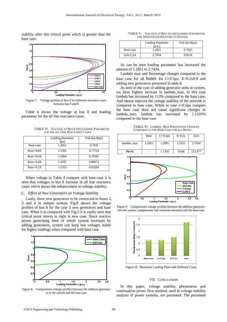
stability after this critical point which is greater than the
base case.
Figure 7. Voltage profiles of Bus 8 for different reactance cases
between bus 8 and 9
Table 4 shows the voltage at bus 8 and loading
parameter for the all line reactance cases.
TABLE IV. VOLTAGE AT BUS 8 AND LOADING PARAMETER
FOR THE ALL LINE REACTANCE CASES
Loading Parameter
(pu)
Volt bus 8(pu)
Base-case 1.2851 0.7635
Reac=0.8X 1.3382 0.77724
Reac=0.6X 1.3964 0.79585
Reac=0.4X 1.4597 0.80673
Reac=0.2X 1.5353 0.83269
When voltage in Table 4 compare with base-case it is
seen that voltages in bus 8 increase in all line reactance
cases which shows the enhancement in voltage stability.
C. Effect of New Generators on Voltage Stability
Lastly, three new generators to be connected to buses 2,
3 and 4 in sample system. Fig.8 shows the voltage
profiles of bus 8 for the case 3 new generators and base
case. When it is compared with Fig.5 it is easily seen that
critical point moves to right in new case. Since reactive
power generating limit of whole system increases by
adding generators, system can keep bus voltages stable
for higher loadings when compared with base case.
Figure 8. Comparisons voltage profiles between the addition generator
in to the system and the base case
TABLE V. VOLTAGE AT BUS 14 AND LOADING PARAMETER
FOR ADDITION GENERATORS TO SYSTEM
Loading Parameter (p.u.)
Volt bus 8(pu)
Base-case 1.2851 0.7635
Gen:2,3,4 2.7434 0.8216
As can be seen loading parameter has increased the
amount of 1.2851 to 2.7434.
Lambda max and Percentage changes compared to the
base case for all buses for C=0.5pu, X=0.2x8-9 and
adding new generators presented in table 6.
As seen in the case of adding generator units to system,
we have highest increase in lambda_max, in this case
lambda has increased by 113% compared to the base case,
And means improve the voltage stability of the network is
compared to base case, While in case c=0.5pu compare
the base case does not cause significant changes in
lambda_max, lambda has increased by 1.1205%
compared to the base case.
TABLE VI. LAMBDA_MAX PERCENTAGE CHANGES
COMPARED TO THE BASE CASE FOR ALL BUSES
Base C=0.5pu X=0.2x Gen
lambda_max 1.2851 1.2995 1.5353 2.7434
Per% - 1.1205 19.46 113.477
Figure 9. Comparisons voltage profiles between the addition generator into the system ,compensator and variation reactance and the base case
Figure 10. Maximum Loading Point with Different Cases
VII. CONCLUSION
In this paper, voltage stability phenomena and
continuation power flow method, used in voltage stability
analysis of power systems, are presented. The presented
International Journal of Electrical Energy, Vol.1, No.1, March 2013
59©2013 Engineering and Technology Publishing
method is applied to 11-Bus two area sample test system.
Voltage magnitude and bus voltage versus Load
parameter curves are obtained for several scenarios by
using a PSAT software which is a one of the toolbox of
MATLAB software. The effect of compensation is
discussed by adding shunt capacitors in different per unit
values to the bus defined in sample system. It is observed
from voltage profiles and voltage magnitude that adding
shunt capacitor to a bus cause to enhance the voltage
stability of whole buses in sample system. Since the shunt
capacitor injects reactive power to system Thus, critical
point occurs in higher loading levels and the magnitudes
of bus voltages will be increased. In addition, the effect of
variation of line reactance on voltage stability is studied
by performing five continuation power flows to the
proposed system. Voltage profiles for different line
reactance cases prove the enhancement in voltage stability.
With decreases of line reactance, reactive power demand
decreases and profile of buses voltages is improved.
Finally, the effect of adding three new generating units is
also observed in sample test system. Adding new
generators improves the voltage stability of sample
system since total power generation increases. In the end
we did a comparison between the three cases studied, and
we find that adding generators to network have a greater
impact on voltage stability and load ability increasing
compared to step-up capacitor and a step down the line
reactance.
REFERENCES
[1] V. Ajjarapu and C. Christy, "The continuation power flow: A tool
for steady state voltage stability analysis," IEEE Trans. on Power
Systems, 7,1992, pp. 426-423 [2] Mehmet B. Kesk_n, "Continuation power flow and voltage
stability in power systems," A Thesis Submitted to the Graduate
School of Natural and Applied Sciences of Middle East Technical University, Sep2007.
[3] M. Larsson, "Coordinated voltage control in electric power systems," Doctoral Dissertation, Lund University, 2000.
[4] Blackout of 2003: Description and Responses. [Online]. Available:
http://www.pserc.wisc.edu/.
[5] R. Natesan and G. Radman, "Effects of STATCOM, SSSC and UPFC on voltage stability," in Proc. The System Theory Thirty-
Sixth Southeastern Symposium, 2004, pp.546-550.
[6] Dobson and H. D. Chiang, "Towards a theory of voltage collapse in electric power systems," Systems& Control Letters, 13, 1989,
pp.253-262. [7] C. A. Canizares, F. L. Alvarado, C. L. DeMarco, I. Dobson, and W.
F. Long, "Point of collapse methods applied to acldc power
systems," IEEE Trans. Power Systems, pp.7673-683, May 1992. [8] P. Kundur, "Power system stability and control," McGraw-Hill,
1994. [9] S. Repo, On-line, "Voltage stability assesment of power system,"
An Approach of Black-box Modelling, Tampere University of
Technology Publications, 2001, pp.344. [10] W. D. Rosehart, C. A. Cañizares, "Bifurcation analysis of various
power system models," International Journal of Electrical Power & Energy Systems, vol.21, 1999, pp.171-182.
[11] C. A. Cañizares, "Voltage collapse and transient energy function
analyses of AC/DC systems," Doctoral Dissertation, University of Wisconsin- Madison, 1991.
[12] A. Edris, "FACTS technology development: An update," IEEE Eng. Rev.20, 2000, pp.4-9.
[13] W. C. Rheinboldt and J. V. Burkardt, "A locally parameterized
continuation process," ACM Transactions on Mathematical Software, 9, 1983, pp.15-35.
[14] R. Kalaivani and V. Kamaraj, "Modeling of shunt FACTS devices for voltage stability enhancement,"61, 2011, pp.144-154 .
Haniyeh Marefatjou is an M.Sc student of electrical engineering at Imam Khomeini
Internatial University (IKIU). Her special fields of interest include Power
System Dynamics, power electronics
Optimization of Power System. She is the author and the coauthor of over 5 technical papers.
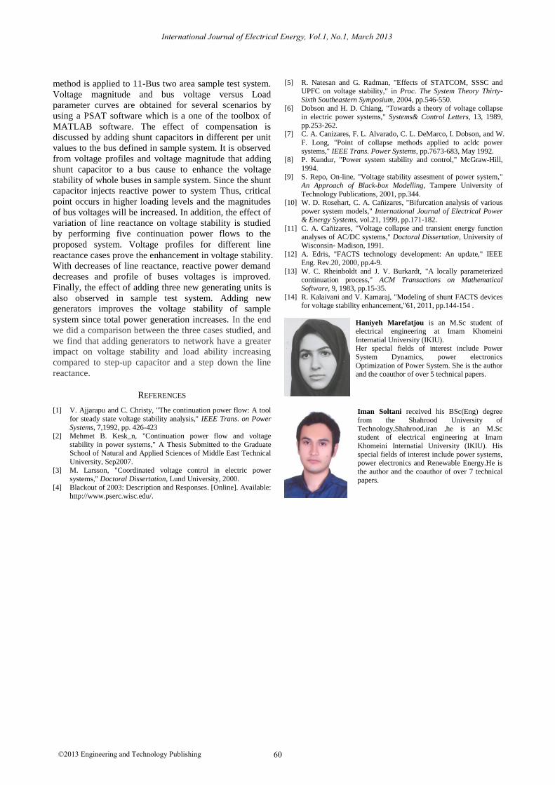
Iman Soltani received his BSc(Eng) degree
from the Shahrood University of Technology,Shahrood,iran ,he is an M.Sc
student of electrical engineering at Imam Khomeini Internatial University (IKIU). His
special fields of interest include power systems,
power electronics and Renewable Energy.He is the author and the coauthor of over 7 technical
papers.
International Journal of Electrical Energy, Vol.1, No.1, March 2013
60©2013 Engineering and Technology Publishing